laboratory assessment of vacuum-based crack monitoring sensor 19 jun 02 ken lacivita materials...
TRANSCRIPT

LABORATORY ASSESSMENT OF VACUUM-BASED CRACK
MONITORING SENSOR
19 Jun 02
LABORATORY ASSESSMENT OF VACUUM-BASED CRACK
MONITORING SENSOR
19 Jun 02
Ken LaCivita
Materials Engineer
Air Force Research Laboratory
Duncan Barton
R&D Manager
Structural Monitoring Systems Ltd.
Ken LaCivita
Materials Engineer
Air Force Research Laboratory
Duncan Barton
R&D Manager
Structural Monitoring Systems Ltd.

2
ACKNOWLEDGEMENTS
• Mr Jack Coate - AFRL/MLSC
• Mr John Brausch - AFRL/MLSA
• Mr Keith McClellan - Structural Monitoring Systems, Ltd.
• Mr Michael Waddell - AFRL/MLO
3
OUTLINE
• Background
• Similar Technologies
• Technology Description
• Testing
• Test Results
• Current Status of CVM Technology
• Conclusions/Recommendations
4
BACKGROUND
• AFRL was introduced to novel crack detection technology - Comparative Vacuum Monitoring (CVMTM)
– Developed by Structural Monitoring Systems (SMS) based in Australia
– Nondestructive Evaluation (NDE) Team had interest in technology and an immediate need for real time crack detection monitoring
• Agreement was made for use of equipment in exchange for an informal assessment

5
SIMILAR TECHNOLOGIES
• Other crack detection/monitoring technologies:
– Crack Detection Gage (filament-type)
– Crack Propagation Gage (filament-type)
– Crack Detection Gage (foil-type)
– Electro Potential DifferenceTest Leads
Test Article

6
TECHNOLOGY DESCRIPTION
• CVM Concept:
– Small volume under vacuum
– Measure air ingress caused by leak (surface crack)
System schematic

7
TECHNOLOGY DESCRIPTION
• Sensor Pad
– Self adhesive, flexible polymer
– Channels molded on one surface
approx. 0.50”
Typical sensor pads

8
TECHNOLOGY DESCRIPTION
• Sensor Pad
– Crack growth beneath pad is detected when “vacuum gallery” is opened to atmospheric pressure
Air/vacuum
leakage
Sensor Pad with Vacuum and Air Channels
Crack Growth

9
TECHNOLOGY DESCRIPTION
• Sensor Pad– Configured for crack detection or crack growth
Sensor pad schematic for crack detection

10
TECHNOLOGY DESCRIPTION
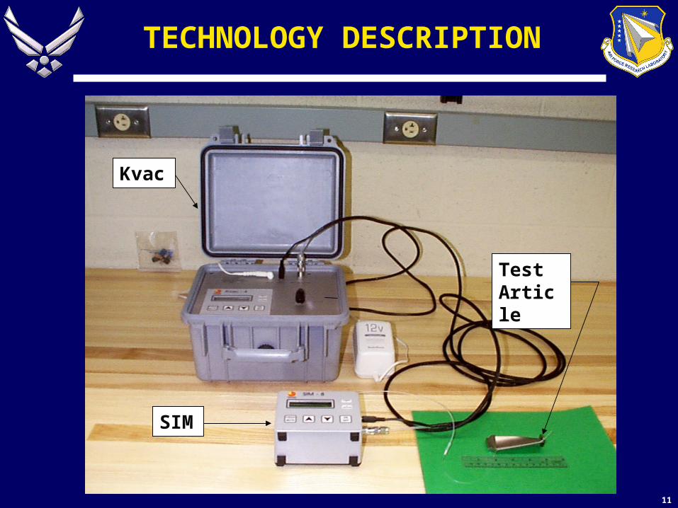
• System Equipment:
– Kvac (constant vacuum source)
• Pulls vacuum on sensor pad
• Reference for relative pressure measurement
– SIM (flow sensing device)
• Monitors relative pressure via low conductance tube
System schematic
11
TECHNOLOGY DESCRIPTION
Kvac
SIM
Test Article
12
TESTING
• Primary purpose:
– Grow natural cracks in engine turbine blades
• 0.020 - 0.080” WITHOUT starter notches
• Secondary purpose:
– Evaluate novel vacuum-based sensor for lab applications
13
TESTING
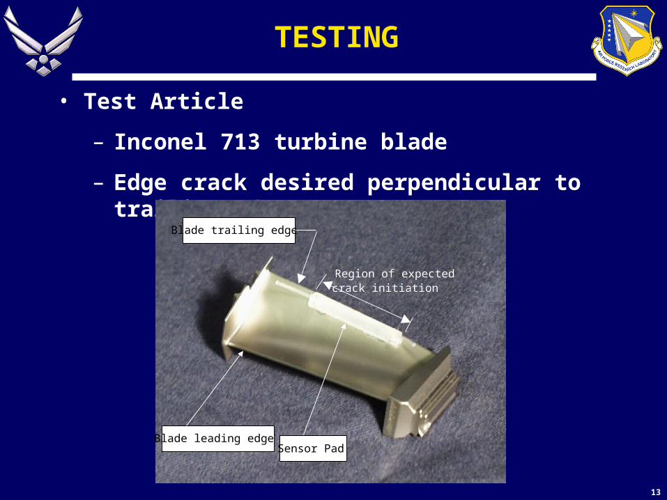
• Test Article
– Inconel 713 turbine blade
– Edge crack desired perpendicular to trailing edge
Blade leading edge
Blade trailing edge
Region of expectedcrack initiation
Sensor Pad

14
TESTING
• Test Approach
– AFRL/MLSC Structural Test Facility
• 3 point cyclic bending
– 10 Hz, increase load every 10000 cycles
Loading fixture
Turbine blade
Sensor pad

15
TEST RESULTS
• Natural cracks detected in two blades
– 0.047”convex side/0.077” concave (sensor) side
– 0.020”convex side/0.045” concave (sensor) side

16
CURRENT STATUS OF CVM TECHNOLOGY
• Failure Modes and Effects Analysis
– Risks being examined for on-aircraft installation
• Independent tests of sensor and adhesive constituents
– Neutral pH
– Negligible mobile ions
• Performance through paint evaluated
– Able to detect cracks through various thicknesses and ages of paint systems (note: paint cracked)
• Effect of long vacuum ducting evaluated
– Sensitivity is governed by gallery spacing

17
CURRENT STATUS OF CVM TECHNOLOGY
• Portable in-field unit evaluation - IN WORK
• Validation trials on flying aircraft - IN WORK
• Long-term environmental program - PLANNED
– Temperature and humidity extremes
– Chemical and UV exposure
– Sensors will be overcoated with sealant

18
CONCLUSIONS/RECOMMENDATIONS
• Crack growth on turbine blade without starter notch proved challenging
– Experimental test method - trial & error approach
– Unpredictable crack growth rates
– Dependent on test operator to stop test once crack detected

19
CONCLUSIONS/RECOMMENDATIONS
• CVM is an effective alternative means for surface crack detection in a lab environment
– 0.020” sensitivity possible
– User-friendly operation
– Adheres with minimal surface prep
– Complex geometry applications
• On-aircraft applications need further evaluation