laboratory evaluation of electrokinetic dewatering of ... · papel, 2003; mineração rio pomba...
TRANSCRIPT

Laboratory Evaluation of Electrokinetic Dewatering ofBauxite Tailings
L. De Leon Ferreira, R.C. Gomes
Abstract. The mining tailings disposal system is often associated to the construction of large retaining systems, either forthe great volume of materials generated by industrial plants or for the impossibility or difficulty of grants for new disposalareas. Due to increasing demand, these impoundments have become much more significant, triggering considerableincrease of risk associated to them. In this context, new techniques must be developed aiming to decrease the volume oftailings produced and the optimization of disposal systems for these materials, particularly in terms of systems includingtailings dewatering techniques. An alternative solution consists in dewater and consolidate mine tailings under currentintermittence, technique called electroosmosis. This paper presents the development of an electroosmotic cell to measurethe electrokinetic flow and the consolidation process of fine tailings under specified boundary conditions. The tailings aregenerated by the process of treatment of bauxite from BPM (Bauxita Paragominas Mining/Brazil), which consist offine-grained materials, with initial solid content of 31%. The results of this experimental study are analyzed and discussedbased on the principles of electrokinetic theory and has shown that the proposed technique would significantly acceleratethe consolidation process of fine tailings (an average solid content of 58% was reached, within a 12-hour period), besidesproviding adequate design parameters for field applications.Keywords: tailings, consolidation, electro-osmosis, electrokinetic phenomena.
1. Introduction
Activities of mineral exploitation are divided basi-cally in the processes of mining extraction, correspondingto the direct exploration of the mineral deposit (often sur-face mining methods in Brazil), and in beneficiation pro-cesses, characterized by the physical and/or chemical oper-ations necessary to change the mineral assembly in formand/or composition, in order to make them suitable to thedesired industrial applications. The final product resultedfrom all this industrial process accounts for only a smallpart of all material extracted from the deposit, therefore it isnecessary the proper disposal of residues generated by allthe activities related to mining. Overburden, the soil androck material that overlies the mine area, removed to ex-pose the ore deposit, are stored in piles. Tailings as watercontaining suspended solids and dissolved materials arecommonly stored in retaining dams.
One of the main processes which results in great envi-ronmental impacts from mining activities is related to thelarge volume of residues generated, in the extraction as wellas in the ore beneficiation processes. So, there is need oflarge areas to dispose these materials, fact which, just by it-self, would imply great concern with this sector of the pro-duction process. In addition to this fact, there are socio-economic and environmental risks associated to the largeretaining structures usually built to store tailings (Vick,1990). On the other hand, tailings are relatively low-density
materials with a high degree of saturation and such condi-tions can generate problems of liquefaction (Gomes et al.,2002; Pirete & Gomes, 2013).
The disposal of mining tailings can be made on thesurface of the ground in the form of piles or in disposal bas-ins formed by retaining dams or dikes, or it is even possibleto be made in underground cavities or in exhausted mines.The tailings disposal techniques have developed signifi-cantly in past years, for instance the use of consolidationmethods, aiming to dewatering the water content in themine pulp and the acceleration of the global process. It is aninteresting way to reduce the total volume to be disposed,with positive consequences in terms of increasing the ca-pacity of preservation of available areas. However, oneproblem linked to tailings thickening is the transportationof these materials until the disposal site. Because it is amore viscous material, in the form of paste or thickenedtailings, the transportation by pumping becomes muchmore expensive in energy consumption as well as in the lo-gistics for the implantation of the pumping system itself.
It is an unquestionable fact that the commodities pro-duction has great importance in the Brazilian economic andsocial development, especially considering the high vol-ume of exports currently presented by these products ofmineral extraction. However, it has become increasinglysurprising the proportions that the so called tailings-retaining structures (especially tailings dams) have gained.Some recent failures of tailings dams in Minas Gerais State
Soils and Rocks, São Paulo, 38(2): 135-147, May-August, 2015. 135
Lucas De Leon Ferreira, Msc., Assistant Professor, Núcleo de Geotecnia da Escola de Minas, Universidade Federal de Ouro Preto, Ouro Preto, MG, Brazil. e-mail:[email protected] César Gomes, DSc., Professor, Núcleo de Geotecnia da Escola de Minas, Universidade Federal de Ouro Preto, Ouro Preto, MG, Brazil. e-mail: [email protected] on September 11, 2013; Final Acceptance on September 15, 2014; Discussion open until August 31, 2015.

(Mineração Rio Verde, 2001; Indústria Cataguases dePapel, 2003; Mineração Rio Pomba Cataguases, 2007), in-volving serious economic and environmental impacts,demonstrate the need for developing more thorough sys-tems for tailings disposal in order to identify, reduce andmanage the possible risks of accidents in a more effectiveway, besides the constant quest for optimization of opera-tional costs and monitoring these structures during theiruseful lives and after their closure.
New approaches for mining tailings disposal systemshave been developed all over the world seeking to suit theseprocedures to the currently existing demands. One of thesealternative approaches for fine tailings disposal, which hasa long consolidation process, is the technique to acceleratethe consolidation process of this material in the form ofpulp through the application of an external electric field(electro-osmosis). The fine tailings is a byproduct of the orebeneficiation process, which usually presents granulometrybelow 400# and low percentage of solids, being, therefore,material associated to large volumes of water. Electro-kinetic consolidation is based on the application of an elec-tric potential difference inside a soil mass, through elec-trodes inserted in this mass, inducing the movement of theliquid phase in the direction of one electrode and enablingthe removal of this corresponding flow of water.
The present study aims to improve the knowledge ofthe electro-osmotic consolidation technique applied to thefine tailings, theme of incipient research in Brazil (Mello etal., 2011). In order to do so, laboratory experiments werecarried out, using one special equipment called electro-kinetic cell, and using some bauxite tailings samples fromBPM (Bauxita Paragominas Mining/Brazil).
2. Electro-Osmosis Phenomena
The combination between hydraulic and electricflows, with their respective gradients, may result in fourwell-known electrokinetic phenomena in materials whichpresent fine granulometry and electrostatically chargedsolid particles, as in the case of clay soils and colloidal sys-tems. These four electrokinetic phenomena are: electropho-resis (movement of particle in a stationary fluid by anapplied electric field), electro-osmosis (movement of liquidpast a surface by an applied electric field), streaming poten-tial (creation of an electric field as a liquid moves along astationary charged surface and sedimentation potential(creation of an electric field when a charged particle movesrelative to stationary fluid). All the electrokinetic phenom-ena involve, essentially, a difference of electric potential,particles with surfaces electrostatically charged and a liquidphase.
Electro-osmosis refers to the movement of bulk liquidrelative to a stationary charged surface due to an appliedelectric field that is primarily generated in the electricaldouble layer (EDL). The mobile portion of the EDL tendsto migrate towards the cathode or anode depending on its
polarity. This electromigration of ions constituting the EDLcauses viscous shearing of the adjacent bulk-liquid mole-cules, ultimately resulting in bulk-liquid motion. For thinEDL’s, the bulk-liquid motion or electro-osmotic flow ischaracterized by a plug-like velocity profile (Fig. 1).
Among many theories which describe electro-osmotic flow, the Helmholtz-Smoluchowski theory is themost accepted and widely adopted by geotechnical engi-neers. This theory is based on a model proposed byHelmholtz (1879) and later refined by Smoluchowski(1914). In this conception, the pore radii are relatively largein comparison to the thickness of the diffuse double layerand the mobile ions are concentrated near the soil-water in-terface.
The zeta potential (�) and the charge distribution inthe fluid adjacent to soil surface play important roles in de-termining the electro-osmotic flow. The � is the electric po-tential developed at solid-liquid interface in response tomovement of colloidal particles; i.e., it is the electrical po-tential at junction between the fixed and the mobile parts ofthe electrical double layer. The � is less than the surface po-tential of a particle and shows the value at the slip plane,which is located at a small unknown distance from the col-loidal surface (Hunter, 1981; Jones et al., 2008).
In this model, the electro-osmotic flow (q) becomes afunction of the electro-osmotic permeability of the soil (ke),of the applied electrical gradient (ie), which is the ratio be-tween the potential difference (E) by the distance betweenthe electrodes (L), and of the area of the section transversalto the flow direction (A) as established in the followingequation (Haussmann, 1990):
q k i Ae e� (1)
The coefficient of electro-osmotic permeability is gi-ven by:
kn
e � ���
�(2)
136 Soils and Rocks, São Paulo, 38(2): 135-147, May-August, 2015.
De Leon Ferreira and Gomes
Figure 1 - Helmholtz-Smoluchowski model for electro-osmosis.

in which � is the zeta potential in V (usually negative forclay soils), � is the soil electric permittivity (F/m in SIunits), � is the fluid viscosity (N.s /m2 in SI units) and n isthe soil porosity.
The factors of the mineralogy which have a positiveeffect for good electro-osmotic phenomena potential(Fig. 2) include: high water content (w), clay minerals withlow cation exchange capacity (CEC), low valence exchan-ge cations, high surface charge density, a high surface areaand nature of water. In terms of water composition, themain aspects are low conductivity (�), low salinity, highpH and low surface charge density per unit pore vo-lume (A0).
Electrochemical reactions associated with the electri-cal field application in tailings are very complex, includingelectrolysis of water (generation of oxygen and hydrogengases), reduction at the cathode and oxidation process at theanode. As a result, the pore water pH of tailings decreases atthe anode and increases at the cathode; the anode corrodesand/or deteriorates quickly if it is made of a material highlysusceptible to corrosion effects.
Besides the parameters associated to the mineralogyof the soil or tailings, and the physico-chemical conditionsof the interstitial fluid, there are still factors related to thearrangement (set up) of the external electric field applied(especially concerning the intensity of electric current andpotential difference), and to the nature, geometry and dis-tance between electrodes (Shang, 1997). This makes thetechnique of electrokinetic consolidation a complex pro-cess based on several variables and demanding, therefore,previous studies in reduced models or laboratory tests,evaluating as many of these variables as possible, in orderto establish parameters to provide applications in fieldscale.
3. Electrokinetic CellIn laboratory, the mechanisms of the electrokinetic
process can be analyzed under well controlled and variedconditions in test columns or in the electrokinetic cells(called EK-cells), equipment which simulates, in reduced
scale, the field setup. The EK-cell tests provide informationon the electro-osmotic permeability as a function of mate-rial density (porosity), applied dc current (current density),voltage (voltage gradient), time and water chemistry. In ad-dition, the EK-cell tests provide information on voltagelosses at interfaces of electrodes and materials (for exam-ple, soils or tailings).
The electrokinetic cell shown in Fig. 3 has been de-veloped to measure the electro-osmotic permeability intailings (or soils) under well-controlled boundary condi-tions (according to Hamir et al., 2001), consisting basicallyof the following devices (Ferreira, 2011):
• acrylic cell;• electrodes;• load application system;• input system and electricity control device;• water circulation system;• monitoring system;• data gathering system.A pair of electrodes and a specimen compartment
compose the electrokinetic cell (Fig. 3). The cell is made of10-mm thick acrylic and bases of polyacetal (polyoxy-methylene) material with the inside dimensions of 15 cm ofdiameter and 35 cm high. The tailings are placed in thespecimen compartment and o-rings are placed on the topand bottom of the cell in order to guarantee the completesealing of the whole system. The water flow through thetailings sample in the cell is essentially one-dimensional(vertical).
The electrodes are placed at both ends of the speci-men compartment. In this study, two types of electrodes inthe form of circular plates were used in the tests for compar-ison: copper and stainless steel (SS316). SS316 is the high-est grade of corrosion resistant stainless steel commercially
Soils and Rocks, São Paulo, 38(2): 135-147, May-August, 2015. 137
Laboratory Evaluation of Electrokinetic Dewatering of Bauxite Tailings
Figure 2 - Influence of soil variables on E-O efficiency (Jones etal., 2008). Figure 3 - Electrokinetic cell and electrodes.

available. The lower electrode has a diameter of 148 mm,while the diameter of the upper electrode is 134 mm (due tothe characteristics of this sealing of the cell). The platesused in the tests have a thickness of 2.0 mm and specificopening areas between 8.0 and 8.7%. In the tests, the elec-trodes are wrapped with geotextile or a filter paper for fil-tering and drainage.
A special designed loading plate (50 cm long x 10 cmwide) equipped with dia1 gauge was placed on the top of thespecimen compartment to apply a surcharge through thedead weights. The water in both reservoirs in the cell is con-trolled at the same level via recharge and discharge tubes toensure different hydraulic gradients or water flow due solelyto the applied dc current. The electrodes were connected to adc power supply (Instrutherm FA 3005 model, with 0-32 Vand 0-3 A ranges); the dc current and voltage were measuredusing a high precision multimeter. The measuring apparatusconsists in three main parts: the transducers (of displace-ment, pressure, load and volume measurement), data acqui-sition board and the management software.
Polarity inversion, i.e. the change between the anodeand cathode has been applied in the performed tests. Underthe normal polarity (NP) mode, the lower electrode of theEK-cell is the anode and upper electrode is the cathode. Un-der the reversed polarity (RP) mode, the applied dc voltageis reversed, i.e., the electrodes are inverted, whereas allother conditions remain the same. The water flow in thetailings reverses direction after the polarity change but thewater discharge was measured through a drainage valve atthe upper part of the cell in both setups (NP or RP modes).
In the experiments performed in this research, otherfollowing design criteria for EK-cell system were consid-ered (Micic, 1998):
• EK-cell had to be water-tight and electricity insu-lated;
• EK-cell had to be big enough to allow a measur-able flow of fluid and electricity through the tail-ings sample under combined influences of imposedhydraulic and electrical gradients;
• to achieve consolidation by electro-osmosis, thedrainage should have been available at the cathode,while the anode could be impermeable;
• an accurately controlled DC electrical potentialcould be applied across the sample; voltage distri-bution in the soil sample and the electrical currentpassing through the sample could be measured as afunction of time;
• volume of flow rate of water through the soil sam-ple could be measured accurately as a function oftime;
• measurements to be made during electrokinetictreatment could not interfere with the process.
The EK-cell apparatus (Ferreira, 2011), as shown inFig. 4, was designed and manufactured for the electro-kinetic bench-scale experiments performed in this study.
4. Tailings Characterization and PropertiesThe electrokinetic tests were performed with tailings
samples from a bauxite mine (MBP) at Paragominas in thenorth of Brazil. Morphologically, the bauxite is thin layer,which covers tens of square kilometers. It lies beneath 5 to20 m of overburden along vast plateaus, which characterizethe ore bodies and were created by differential erosion ofthe plain where the laterites developed. On average, the oreis about 1.5 meters thick and the overburden is 12 m thick.The overburden consists of a thick oxisol and the top 1.5 to2 m of the laterites, of which the bauxite layer is a part. Themain constituents of the overburden are silt and clay.
Paragominas bauxite is washed to remove the freeclay that it contains, before shipping to refineries. Washingleaves about 30% of the run-of-mine ore at the mine, in theform of clay rich tailings, which would otherwise reducethe alumina content of the product, increase the refinerycost and increase the volume of red mud for disposal at therefinery site.
In the MBP concept, run-of-mine bauxite is reducedbelow 8 inches through two stages of double roll crushers.The crushed ore is fed to a SAG mill, usually part of the pri-mary stage in the grinding process in mining operations,which continues reduction and slurries the ore with water.From the SAG mill, most of the slurry goes to a ball mill,which adjusts the particle size distribution of the solids tomeet the specification for pipeline transport. Between thetwo mills, larger pebbles exiting the SAG mill are crushedto control the ball mill feed top size and the greater mass ofthe slurry is diluted and then classified by hydro-cyclonesinto three streams. The first stream, with particles greater
138 Soils and Rocks, São Paulo, 38(2): 135-147, May-August, 2015.
De Leon Ferreira and Gomes
Figure 4 - Schematic of electrokinetic testing cell.

than 150# is directed to the ball mill and the second stream,with particles between 150# and 400#, bypasses the ballmill directly to the product tank. The third stream, with par-ticles below 400#, is waste and proceeds to the tailingsthickener. Tailings are approximately 30% of the dry massof ore, or about 0.38 million tons for each million ton ofproduct, or 220 million tons over the project lifetime.
The deposition area is located in a valley not far fromthe plant. Tailings are confined laterally by the valley sidesand longitudinally by dykes, which divide the total area intofour storage basins. Dumping is cyclic; each basin is usedfor 10 days then allowed to rest for 30 days before repeatingthe cycle. During the resting time, the tailings consolidateand dry to reach solids content of 70 to 80%, at which pointthey should be stable and occupy their minimum volume.However, further expansion and production for 40 years atthe maximum rate require extensions to the current tech-nique, and so, electrokinetic consolidation can be an inter-esting alternative solution.
The tailings and original supernatant were directlycollected from the spigot and sent to the laboratory insealed plastic containers, and used in all tests. Table 1 andTable 2 present the main geotechnical and chemical proper-ties of the tailings (obtained by the ICP technique), respec-tively.
The results show the predominant presence of the ele-ments: iron (Fe), aluminum (Al), titanium (Ti), zirconium(Zr) and sulfur (S) with all the other elements presentingmuch lower concentrations. There is no silicon (Si) in thechemical analysis of the tailings due to the technique ofpreparation of the sample for test performance. In this case,the sample, air dried, was solubilized in fluoridic acid (HF),which causes the elimination of the silicon by evaporation.
The grain size distributions, with and without use ofdeflocculant during the test, are shown in Table 3. The re-sults enable us to verify the effective action of the additiveincorporated to the tailings in relation of clay particle floc-
culation (in situ situation), indicating that the tailings solidsconsist essentially of fines particles. The tailings have highplasticity with a plasticity index of 33.1%.
The results of X-ray of tailings using a powderdiffractometer are indicated in Fig. 5, plotted as 2� angle onthe x axis vs. X-ray intensity as measured by the detector onthe y axis, usually expressed as counts per second. Peaksare labeled by d-spacings (Å) indicating the predominantpresence of kaolinite, goethite, gibbsite and hematite.
5. Electrokinetic Dewatering TestsThe tailings slurry was agitated by a mixer to a uniform
consistency, and then it was poured into the cell withpreinstalled electrodes. After the cell was filled, the slurrywas allowed to settle by gravity until the water flow throughthe bottom drains stopped and a soft sediment was formed.During the sedimentation stage, the drain valves at the top ofthe cell were open and drainage water was collected. Elec-trokinetic tests were performed immediately after sedimen-tation stage. In the electrokinetic tests, the applied voltage inall tests was 15 V in order to ensure an uniform voltage gra-dient along the tailings samples of 95 V/m.
Tests were conducted to study the combined effect ofsurcharge and electro-osmosis, using the following termi-
Soils and Rocks, São Paulo, 38(2): 135-147, May-August, 2015. 139
Laboratory Evaluation of Electrokinetic Dewatering of Bauxite Tailings
Figure 5 - X-ray diffraction pattern for bauxite tailings.
Table 1 - Tailings geotechnical properties.
Specific gravity 2.67
Liquid limit 64%
Plasticity Limit 31%
Plasticity Index 33%
pH 5.33
CEC (cation exchange capacity) 4.88 cmol/kg
Hydraulic conductivity (for initial solidscontent= 30%)
5.7 x 10⁻⁷ m/s
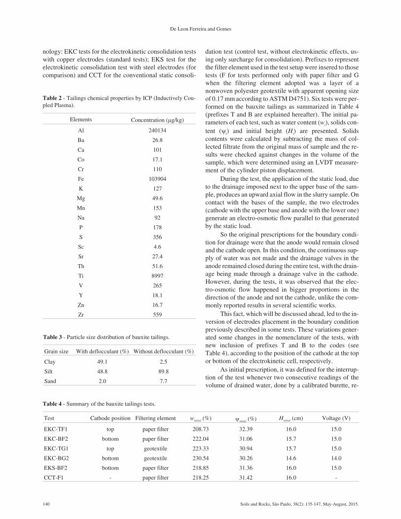
nology: EKC tests for the electrokinetic consolidation testswith copper electrodes (standard tests); EKS test for theelectrokinetic consolidation test with steel electrodes (forcomparison) and CCT for the conventional static consoli-
dation test (control test, without electrokinetic effects, us-ing only surcharge for consolidation). Prefixes to representthe filter element used in the test setup were insered to thosetests (F for tests performed only with paper filter and Gwhen the filtering element adopted was a layer of anonwoven polyester geotextile with apparent opening sizeof 0.17 mm according to ASTM D4751). Six tests were per-formed on the bauxite tailings as summarized in Table 4(prefixes T and B are explained hereafter). The initial pa-rameters of each test, such as water content (wi), solids con-tent (i) and initial height (Hi) are presented. Solidscontents were calculated by subtracting the mass of col-lected filtrate from the original mass of sample and the re-sults were checked against changes in the volume of thesample, which were determined using an LVDT measure-ment of the cylinder piston displacement.
During the test, the application of the static load, dueto the drainage imposed next to the upper base of the sam-ple, produces an upward axial flow in the slurry sample. Oncontact with the bases of the sample, the two electrodes(cathode with the upper base and anode with the lower one)generate an electro-osmotic flow parallel to that generatedby the static load.
So the original prescriptions for the boundary condi-tion for drainage were that the anode would remain closedand the cathode open. In this condition, the continuous sup-ply of water was not made and the drainage valves in theanode remained closed during the entire test, with the drain-age being made through a drainage valve in the cathode.However, during the tests, it was observed that the elec-tro-osmotic flow happened in bigger proportions in thedirection of the anode and not the cathode, unlike the com-monly reported results in several scientific works.
This fact, which will be discussed ahead, led to the in-version of electrodes placement in the boundary conditionpreviously described in some tests. These variations gener-ated some changes in the nomenclature of the tests, withnew inclusion of prefixes T and B to the codes (seeTable 4), according to the position of the cathode at the topor bottom of the electrokinetic cell, respectively.
As initial prescription, it was defined for the interrup-tion of the test whenever two consecutive readings of thevolume of drained water, done by a calibrated burette, re-
140 Soils and Rocks, São Paulo, 38(2): 135-147, May-August, 2015.
De Leon Ferreira and Gomes
Table 2 - Tailings chemical properties by ICP (Inductively Cou-pled Plasma).
Elements Concentration (�g/kg)
Al 240134
Ba 26.8
Ca 101
Co 17.1
Cr 110
Fe 103904
K 127
Mg 49.6
Mn 153
Na 92
P 178
S 356
Sc 4.6
Sr 27.4
Th 51.6
Ti 8997
V 265
Y 18.1
Zn 16.7
Zr 559
Table 3 - Particle size distribution of bauxite tailings.
Grain size With deflocculant (%) Without deflocculant (%)
Clay 49.1 2.5
Silt 48.8 89.8
Sand 2.0 7.7
Table 4 - Summary of the bauxite tailings tests.
Test Cathode position Filtering element winitial (%) initial (%) Hinitial (cm) Voltage (V)
EKC-TF1 top paper filter 208.73 32.39 16.0 15.0
EKC-BF2 bottom paper filter 222.04 31.06 15.7 15.0
EKC-TG1 top geotextile 223.33 30.94 15.7 15.0
EKC-BG2 bottom geotextile 230.54 30.26 14.6 14.0
EKS-BF2 bottom paper filter 218.85 31.36 16.0 15.0
CCT-F1 - paper filter 218.25 31.42 16.0 -
mained constant within an interval of 2 h. Such procedureresulted in a standard time for test of 24 h, which was thenadopted as reference for all the series of tests. As exposedpreviously, the voltage applied to the electrodes was keptconstant (over a voltage gradient of 95 V/m) and withoutpolarity inversion during the execution of all tests.
The results obtained are graphically presented ac-cording to the variation of the following magnitudes withthe time and during the EK-treatment period:
• Volume of drained water;• Electric current variation;• Axial deformation;• Porepressures generated at the base of the electro-
kinetic cell;• pH of drained water.The results of the tests are presented in next sections,
for EKC tests, respectively (using for comparison the re-sults from EKS test and CCT control test). They are re-ported in terms of changes of sample volume (settlementand expelled water), porepressures, current magnitudes andchemical properties of collected water at the completion ofthe tests. During the tests, the variations of water contentsand of solids contents were also registered at three distinctregions of the sample: near the top electrode, in the middleof the sample, and near the bottom electrode.
6. EKC Test Results
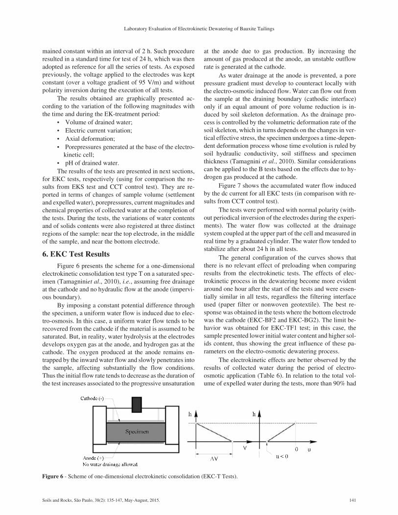
Figure 6 presents the scheme for a one-dimensionalelectrokinetic consolidation test type T on a saturated spec-imen (Tamagniniet al., 2010), i.e., assuming free drainageat the cathode and no hydraulic flow at the anode (impervi-ous boundary).
By imposing a constant potential difference throughthe specimen, a uniform water flow is induced due to elec-tro-osmosis. In this case, a uniform water flow tends to berecovered from the cathode if the material is assumed to besaturated. But, in reality, water hydrolysis at the electrodesdevelops oxygen gas at the anode, and hydrogen gas at thecathode. The oxygen produced at the anode remains en-trapped by the inward water flow and slowly penetrates intothe sample, affecting substantially the flow conditions.Thus the initial flow rate tends to decrease as the duration ofthe test increases associated to the progressive unsaturation
at the anode due to gas production. By increasing theamount of gas produced at the anode, an unstable outflowrate is generated at the cathode.
As water drainage at the anode is prevented, a porepressure gradient must develop to counteract locally withthe electro-osmotic induced flow. Water can flow out fromthe sample at the draining boundary (cathodic interface)only if an equal amount of pore volume reduction is in-duced by soil skeleton deformation. As the drainage pro-cess is controlled by the volumetric deformation rate of thesoil skeleton, which in turns depends on the changes in ver-tical effective stress, the specimen undergoes a time-depen-dent deformation process whose time evolution is ruled bysoil hydraulic conductivity, soil stiffness and specimenthickness (Tamagnini et al., 2010). Similar considerationscan be applied to the B tests based on the effects due to hy-drogen gas produced at the cathode.
Figure 7 shows the accumulated water flow inducedby the dc current for all EKC tests (in comparison with re-sults from CCT control test).
The tests were performed with normal polarity (with-out periodical inversion of the electrodes during the experi-ments). The water flow was collected at the drainagesystem coupled at the upper part of the cell and measured inreal time by a graduated cylinder. The water flow tended tostabilize after about 24 h in all tests.
The general configuration of the curves shows thatthere is no relevant effect of preloading when comparingresults from the electrokinetic tests. The effects of elec-trokinetic process in the dewatering become more evidentaround one hour after the start of the tests and were essen-tially similar in all tests, regardless the filtering interfaceused (paper filter or nonwoven geotextile). The best re-sponse was obtained in the tests where the bottom electrodewas the cathode (EKC-BF2 and EKC-BG2). The limit be-havior was obtained for EKC-TF1 test; in this case, thesample presented lower initial water content and higher sol-ids content, thus showing the great influence of these pa-rameters on the electro-osmotic dewatering process.
The electrokinetic effects are better observed by theresults of collected water during the period of electro-osmotic application (Table 6). In relation to the total vol-ume of expelled water during the tests, more than 90% had
Soils and Rocks, São Paulo, 38(2): 135-147, May-August, 2015. 141
Laboratory Evaluation of Electrokinetic Dewatering of Bauxite Tailings
Figure 6 - Scheme of one-dimensional electrokinetic consolidation (EKC-T Tests).

already been extracted in all electrokinetic arrangementsafter the first 12 h of the test. For the sake of comparison,this table also shows the percentage of drained water duringthe first 8 hours of test.
The consolidation process under static load (15 kPa)and electric potential(0.95 V/cm) is associated with a defor-mation in the medium which only occurs in the vertical di-rection (settlements). The settlements of the tailings speci-mens during the EKC tests (compared with results from CScontrol test under static load only) are shown in Fig. 8. In alltests, the settlements of the tailings specimens were mea-sured by a LVDT attached on the top of the loading plate.
Except for test TF1, which presented a discrepant per-formance (as already evidenced by the results of the testconcerning the volume of drained water), all other tests pro-vided final deformations equivalent and of the same orderof magnitude as the value obtained in the conventional con-solidation test (deformations in the range 57% to 59% after24 h). On the other hand, the results indicate that the consol-idation process is considerably accelerated when an electricfield is applied to the tailings sample (Fig. 9). The researchshowed that the application of the electric gradient of0.95 V/cm reduces the consolidation time by up to 60%.
Figure 10 shows the distribution of the excess porepressures at the bottom of the cell in the tests when both
static load and electric field are applied. The results showsignificant variations of pore water pressures at the bottomof the cell in the electrokinetic tests, in comparison with theconventional consolidation test (rising flow inside the cellas exclusive effect from loading). The initial value of thepore pressure at the bottom of the cell (about 20 kPa) corre-sponds to the sum of the excess of pressure generated by ap-plying the vertical load (15 kPa) and due to the weight oftailings sample and water column pressure from the upperdrainage tube of the cell.
It can be seen that pore pressure progressively de-creases near the lower electrode region. The null values ofpore water pressures (indicated over the t-axis) should beconsidered only like the final of positive pore water pres-sures; in reality, from this point on, negative pore waterpressures tend to be developed. The consolidation processis directly related to the development of negative excesspore pressure in later stages of electrokinetic process.Thereduction of excess pore pressures induces the increase indensity via the increase of effective stresses.
Electro-osmotic consolidation (and not properly theelectrokinetic dewatering) reduced substantially the watercontent of the testing samples. At the end of each test, the fi-nal water contents and solids contents of the tailings sam-
142 Soils and Rocks, São Paulo, 38(2): 135-147, May-August, 2015.
De Leon Ferreira and Gomes
Figure 7 - EKC Tests: Volume of drained water vs. time ofelectrokinetic treatment.
Figure 8 - EKC Tests: Settlements of the tailings specimens vs.time of electrokinetic treatment.
Table 6 - Volume of drained water in the tests.
Test % of volume drained in 8 h % of volume drained in 12 h Total volume of drained water (mL)
EKS-TF1 70.96 88.53 1453.0
EKS-BF2 87.38 97.42 1664.0
EKS-TG1 81.53 94.00 1570.0
EKS-BG2 93.44 99.00 1494.0
CCT-F1 69.65 85.24 1579.0
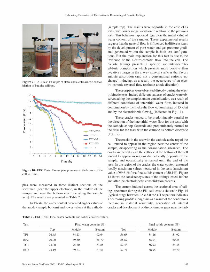
ples were measured in three distinct sections of thespecimen (near the upper electrode, in the middle of thesample and near the bottom electrode along the sampleaxis). The results are presented in Table 7.
In T tests, the water content presented higher values atthe anode (sample bottom) and lower values at the cathode
(sample top). The results were opposite in the case of Gtests, with lower range variation in relation to the previoustests. This behavior happened regardless the initial value ofwater content of the samples. These experimental resultssuggest that the general flow is influenced in different waysby the development of pore water and gas pressure gradi-ents generated within the sample in both test configura-tions. But the main explanation for this fact is due to theinversion of the electro-osmotic flow into the cell. Thebauxite tailings presents a specific kaolinite-goethite-gibbsite composition which presents more positive thannegative charges in the clayey mineral surfaces that favorsanionic absorption (and not a conventional cationic ex-change) inducing, as a result, the occurrence of an elec-tro-osmotic reversal flow (cathode-anode direction).
These aspects were observed directly during the elec-trokinetic tests. Indeed different patterns of cracks were ob-served along the samples under consolidation, as a result ofdifferent conditions of interstitial water flow, induced incombination by the hydraulic flow h (surcharge of 15 kPa)and by the electrokinetic flow ek (indicated in Fig. 11).
These cracks tended to be predominantly parallel tothe direction of the interstitial water flow for the tests withthe cathode as top electrode and predominantly normal tothe flow for the tests with the cathode as bottom electrode(Fig. 12).
The cracks in the test with the cathode at the top of thecell tended to appear in the region near the center of thesample, disappearing as the consolidation advanced. Thecracks in the tests with the cathode at the bottom of the celltended to appear in regions diametrically opposite of thesample, and occasionally remained until the end of thetests. In the region of the cracks, the water content assumedlocally maximum values measured in the tests (maximumvalue of 99.61% for a final solids content of 50.1%). Figure13 shows the consistency states of the tailings tested, beforeand after the electrokinetic consolidation process.
The current induced across the sectional area of tail-ings specimen during the EK-cell tests is shown in Fig. 14(typical range between 1.5 e 5.0 mA). The pattern indicatesa decreasing profile along time as a result of the continuousincrease in material resistivity, generation of internalcracks and development of discontinuous gaps near the tail-
Soils and Rocks, São Paulo, 38(2): 135-147, May-August, 2015. 143
Laboratory Evaluation of Electrokinetic Dewatering of Bauxite Tailings
Figure 9 - EKC Test: Example of static and electrokinetic consol-idation of bauxite tailings.
Figure 10 - EKC Tests: Excess pore pressures at the bottom of thecell vs. time.
Table 7 - EKC Tests: Final water contents and solids contents values.
Test Final water contents (%) Final solids contents (%)
Top Middle Bottom Top Middle Bottom
TF1 76.45 84.23 92.64 56.68 54.26 51.92
BF2 70.00 69.30 65.70 58.82 58.94 60.35
TG1 74.00 75.70 83.88 57.48 56.92 54.38
BG2 73.19 69.63 67.51 57.74 58.95 59.70

ings-electrode interfaces due to corrosion effects on theelectrode material.
The initial values of electric current were higher inthe tests having the cathode as the top electrode. The big-gest drop of current was measured in the TG1 test, usinggeotextile as filtering element at the top of the cell (a reduc-tion of around 77.5% in the current magnitude), whereasthe smallest variation occurred in the BG2 test, using geo-textile as filtering element and the cathode as bottom elec-trode (reduction of 50.0% in the electric current during thetest).
The changes in the tailings pore water pH are pre-sented in Fig. 15. The values were measured directly fromthe expelled water during the electrokinetic tests and col-lected at the drainage system coupled at the upper part ofthe cell. The tailings pore water pH increases at the cathodeand decreases at the anode due to the effects of the elec-tro-osmotic reversal flow and hydrolysis reactions.
Thus, in the surroundings zones of the cathode, theenvironment tends to become basic (condition observed inthe tests TF1 and TG1, with the cathode being the drainageinterface). TF1 test presented, in this region, pH values near10.0, while in TG1 test, water pH reached 9.7. On the other
hand, the concentration of hydrogen ions tends to produceacid media in the surrounding zones of the anode (condition
144 Soils and Rocks, São Paulo, 38(2): 135-147, May-August, 2015.
De Leon Ferreira and Gomes
Figure 11 - Cracks pattern and flow conditions in the tested sam-ples.
Figure 12 - Cracks pattern: (a) EKC-TF1 test; (b) EKC-BF2 test.
Figure 13 - Consistency states of the tailings tested (before and af-ter the EKC test).
Figure 14 - EKC Tests: Electrical current vs. time of electro-kinetic treatment.

observed in BF2 and BG2 tests, with the anode being thedrainage interface). The values of water pH in this regionwere practically invariable during the tests, reaching mini-mum values of 5.17 for BG2 test. The pH control for tail-ings pore water constitutes a relevant procedure in order tosustain a continuous water flow under dc current.
The coefficients of electro-osmotic permeability (ke)relate the velocity of the water flow and applied voltagegradient and are calculated from Eq. 1. Because tailings arehighly variable in mineralogy, particle size and water che-mistry, ke results also show a great range along the time(Fig. 16). The initial ke values measured from EKC testsvaried between 7.6 x 10⁻⁸ m2/Vs and 9.5 x 10⁻⁸ m2/Vs, whichdecreased with time and tended to a mean value of1.0 x 10-10 m2/Vs after 24 h of voltage application.The meanhydraulic conductivity after the tests was estimated in over2.1 x 10-8 m/s (final = 60%) compared to the initial value of5.7 x 10-7 m/s (initial = 30%). This variation may be attrib-uted to blockage of pores in the tailings sample associatedwith electrokinetic phenomena.
Chemical analyses results of drained water during theCS-F1 and EKC-BG2 tests are presented in Table 8 forcomparison with those obtained intailings. In both tests, thewater samples were collected in the first 30 min of the tests.
Comparing the original tailings solution composition(Table 2) and the consolidation tests drained water samples(Table 8), it can be observed a significant reduction of thechemical element concentrations with time in EK tests. Thevariations on the concentrations of these chemical elementsin the drained water happen due to the ionic migration re-sulting from the potential difference applied, and due to thecationic changes occurring during the electro-osmotic con-solidation process.
The exponential increase of copper concentration inthe second analysis is a straight result of the high corrosioneffects of the copper electrodes used in the tests of electro-kinetic consolidation. As a result, in the conventional con-
solidation test, by action of axial loading only, the copperconcentration was 13.3 �g/L of water. In the electrokineticconsolidation test, however, this concentration was3952 �g/L, approximately 298 times higher than the previ-ous test.
Due to the substantial effects of corrosion on copperelectrodes, the EKC-BF2 test was remade for purpose ofcomparison using stainless steel (SS316) cathodes whichpresent a higher grade of corrosion resistance (the new testwas named as EKS – BF2, whereas all other conditions re-mained the same). The results show similar behaviorbetween the tests, in relation to the reversal flow and mea-sured quantities, including voltage losses and electric fieldsgenerated along the time. Figure 17 presents the corre-sponding pore pressure profiles induced in both tests. Thevalues of electroosmotic permeability were equivalent andindependent of electrode materials but, unfortunately, thenew drained water composition was not spared for compar-ison with previous tests.
7. Conclusions
The processes of electro-osmotic consolidation anddewatering of mining tailings vary according to specificconditions presented by each project, because of the parti-cle mineralogy, the chemical composition of the interstitialfluid, electrodes arrangement, and boundary conditions ofdrainage. Therefore, the design of structures which useelectrokinetic phenomena as accelerators for the process ofconsolidation of mining tailings requires previous labora-tory analyses in order to establish general guidelines for itsapplication to real problems.
It is important to consider the complexity of electro-kinetic phenomena in tailings processed in an industrialplant, characterized by milling and addition of several che-mical products at different stages of operation. In the spe-cific case of bauxite tailings from MBP (Paragominas -
Soils and Rocks, São Paulo, 38(2): 135-147, May-August, 2015. 145
Laboratory Evaluation of Electrokinetic Dewatering of Bauxite Tailings
Figure 15 - EKC Tests: Tailings pore water pH vs. time ofelectrokinetic treatment.
Figure 16 - EKC Tests: coefficients of electro-osmotic perme-ability (ke) vs. time.

PA), very fine residues are generated (particles smaller than400 #) which are treated with conventional thickeners andenhanced with synthetic flocculants for pH adjustmentsand optimization of the consolidation processes. This con-dition is very different of dewatering applications by theelectro-osmotic technique for granular tailings (Shang &Mohamedelhassan, 2001).
The conjugation of a specific clay mineral composi-tion, an surcharge of 15 kPa and the application of an exter-nal electric field of 0.95 V/cm, induced an electro-osmoticreversal flow in the direction cathode - anode, regardlessthe different placements and nature of the electrodes (withdrainage always made by the superior electrode of the
setup). Such flow condition is opposite to the electro-osmotic flow commonly observed, resulting from the min-eralogy presented by the tailings used as well as from itspH, fact already observed in other researches related toproblems of soils decontamination (Souza, 2002).
The device designed and developed in this study en-ables a large versatility of tests, including the use of elec-trodes of distinct natures, application of external loadingsand adoption of different boundary conditions of drainageof the samples (tailings or soils). The research showed thatthe application of the electric gradient of 0.95 V/cm reducesthe consolidation time by about 60%. The adoption of stain-less electrodes material solved the problems due to the highcorrosion effects observed in the copper electrodes in theelectrokinetic dewatering tests. The results obtained werepertinent, representative of the conditions inherent to thephenomena of electrokinetic nature, liable of repeatabilityand of direct confrontation among themselves.
References
Ferreira, L.D. (2011). Study of Electrokinetic Phenomenain Consolidation Process of Mining Tailings (in Portu-guese). MSc Thesis, Graduate Program in GeotechnicalEngineering, Federal University of Ouro Preto, OuroPreto, 141 p.
Gomes, R.C.; Pereira, E.L.; Ribeiro, L.F.M. & Silva, J.T.G.(2002). Evaluation of liquefaction potential of finegrained tailings. In: 4th International Congress on Envi-ronmental Geotechnics - 4ICEG, Rio de Janeiro. Taylor& Francis; Lisse, v. 1, pp 329-333.
Hamir, R.B.; Jones, C.J.F.P. & Clarke, B.G. (2001). Elec-trically conductive geosynthetics materials for consoli-dation and reinforced soil. Geotextiles and Geomem-branes, 19(8):445-482.
Hausmann, M.R. (1990). Engineering Principles of GroundModifications. McGraw Hill Publishing Company,New York, 363 p.
Helmholtz, H. (1879) Studien über electrische grenzschi-chten. Annalen der Physik und Chemie, 243:337-82.
Hunter, J.R. (1981). Zeta Potential in Colloid Science. Aca-demic Press, London, 386 p.
Jones, C.J.F.P.; Lamont-Black, J.;Glendinning, S.; Ber-gado, D.; Eng, T.; Fourie, A.; Liming, H.; Pugh, C.;Romantshuk, M.; Simpanen, S. & Yan-Feng, Z. (2008).Recent research and applications in the use of elec-tro-kinetic geosynthetics. EuroGeo4; Keynote Paper,30 p.
Mello, C.M.A.R.; Tibana, S.; Saboya, F.; Reis, R.M.;Del’Aguila, V.M. & Silva, E. Z. (2011). Physical mod-els consolidation by electro-osmosis. In: 14º Panameri-can Conference on Soil Mechanics and GeotechnicalEngineering, Toronto. 2011 Pan-Am CGS Geotechni-cal Conference.
146 Soils and Rocks, São Paulo, 38(2): 135-147, May-August, 2015.
De Leon Ferreira and Gomes
Table 8 - Chemical analysis of drained water in the CCT-F1 andEKC-BG2 tests.
Element Concentration (�g/L)
CCT-F1 Test EKC-BG2 Test
Ba 1.13 3.1
Ca 0.978 2.36
Cu - 3952
K 1.16 1.18
Mg 0.0397 0.0963
Mn 8.06 23.1
Na 4.57 1.9
Ni - 18.8
P < QL* 0.282
S 0.187 0.769
Si 0.529 0.917
Sr 4.53 11.2
Zn 10.7 88.8
*QL – Quantification Limit.
Figure 17 - EKC and EKS Tests: Excess pore pressures at the bot-tom of the cell vs. time.
Micic, S. (1998). Electrokinetic Strengthening of Soft Ma-rine Sediments. MSc Thesis, University of Western On-tario, Canada, 340 p.
Pirete, W, & Gomes, R.C. (2013). Tailings liquefactionanalysis using strength ratios and SPT/CPT Results.Soils and Rocks, 36(1):37-53.
Shang, J.Q. (1997). Electrokinetic sedimentation: a theoret-ical and experimental study. Canadian GeotechnicalJournal, 34,:305-314.
Shang, J.Q. & Mohamedelhassan, E. (2001). Eletrokineticdewatering of Eneabba West Mine tailings: a laboratoryexperimental study. Soft Ground Technology Confer-ence, Geotechnical Special Publication No. 112, ASCE,the Netherlands, p. 346-357.
Smoluchowski, M. (1914). In: L. Graetz (ed.), Handbuchder Elektrizitat and Magnetismus, Vol. 2, J.A. Barth,Leipzig.
Souza, M.V. (2002). Electrokinetic Transportation of Gas-oline and Oil through a Residual Gneissic Soil and OilSludge from Campos Basin. MSc Thesis, PontificalCatholic University of Rio de Janeiro, Civil Engi-neering Department, 137 p.
Tamagnini, C.; Jommi, C. & Cattaneo, F. (2010). A modelfor coupled electro-hydro-mechanical processes in fine-grained soilsaccounting for gas generation and trans-port. Annals of the Brazilian Academy of Sciences,82(1):169-193.
Vick, S.G. (1990). Planning, Design, and Analysis of Tail-ings Dams. BiTech Publishers Ltd, Vancouver, 369 p.
Soils and Rocks, São Paulo, 38(2): 135-147, May-August, 2015. 147
Laboratory Evaluation of Electrokinetic Dewatering of Bauxite Tailings