laboratory simulation of laser communications from a
TRANSCRIPT
The Space Congress® Proceedings 1968 (5th) The Challenge of the 1970's
Apr 1st, 8:00 AM
Laboratory Simulation of Laser Communications from a Reentry Laboratory Simulation of Laser Communications from a Reentry
Vehicl Vehicl
T. A. Barr U.S. Army Missile Command, Redstone Arsenal, Alabama
Charles Cason U.S. Army Missile Command, Redstone Arsenal, Alabama
Follow this and additional works at: https://commons.erau.edu/space-congress-proceedings
Scholarly Commons Citation Scholarly Commons Citation Barr, T. A. and Cason, Charles, "Laboratory Simulation of Laser Communications from a Reentry Vehicl" (1968). The Space Congress® Proceedings. 2. https://commons.erau.edu/space-congress-proceedings/proceedings-1968-5th/session-9/2
This Event is brought to you for free and open access by the Conferences at Scholarly Commons. It has been accepted for inclusion in The Space Congress® Proceedings by an authorized administrator of Scholarly Commons. For more information, please contact [email protected].
LABORATORY SIMULATION OF LASER COMMUNICATIONS FROM A REENTRY VEHICLE
T. A. Barr, Jr. and Charles Cason U.S. Army Missile Command, Redstone Arsenal, Alabama 35809
Laser communications has been proposed as one way to solve the "radio blackout" problem during the reentry of a manned vehicle. The AMICOM 8,000 kW Plasma Facility (PF) 1 ' 2 was used in a set of experiments to simulate the conditions expected during the reentry of a high speed vehicle. This experimental study was designed to simulate a typ ical theoretical Apollo test vehicle reentry trajectory. No plasma effects on the transmitted laser beam were expected or observed since the cutoff frequency due to electron collision rates was calculated to be in the microwave region and not in the optical or infrared region. However, the high temperature gradients and anticipated gas density variations in the flow field were throught to be potential sources of local index of refrac tion fluctuations. These fluctuations may generate scintillation effects in the laser beam which would be expected to reduce the effectiveness of laser communications.
The limitation of maximum power in the PF flow field, approximately 4 megawatts, prevented simultaneous duplication of the desired Reynolds number (R ^ 7 X 10⁴ per meter) and the stagnation point enthalpy (h/RTo « 100). However, by varying the PF parameters to lower the enthalpy, the Reynolds number, or both a satisfactory simulation of conditions just before the termination of "radio blackout" was obtained. The region of the "reentry corridor" simulated in this investigation is near 60 km altitude and 3.9 km/sec velocity. The Reynolds numbers were based on a characteris tic length of 1 meter for the vehicle and 0.1 meter for the model. A flat disk model, normal to the PF flow stream, was used to generate the required local flow field for the laser experiments. The disk diameter, 0.09 m, was determined by the PF flow field blockage parameter; this also estab lished the characteristic Reynolds number length (j£• Ki 0.1 m) for the experiments. The disk was followed by a smaller diameter cylindrical after body approximately 25 cm long containing instru mentation. The cylinder also had a pair of windows situated so the laser beam could pass through the flow field immediately behind the disk. An ampli tude modulated He-Ne laser was used as a signal source with a photomultiplier tube as a detector. Model stagnation pressure and transmitted laser signals were recorded on an analog tape recorder. A frequency spectrum analyzer was used to analyze the data.
The experiments performed to-date have been in the laminar flow regime and our test results indicate that laser communications should be satisfactory. However, a residual perturbation in modulated laser signals appears to exist in this regime, even after account is taken of the perturbations introduced by the experiments. This indicates that some low level scintillation effects may be present even for laminar flows at high total gas enthalpy. These effects may become important for the high velocity turbulent flow case.
Experiment Design
The purpose of the research reported here was; 1) To determine the simulation capability of the PF for reentry vehicle laser communications experiments. 2) To measure the effects of undeter mined parameters which might influence laser com munications from the reentry vehicle to a ground station for the specified PF simulation regions. The first part required the comparison of the PF's capabilities to the requirements imposed by the vehicle's trajectory. The second part was the experimental measurement of the laser signal's response characteristics after transmission through a model tested in the PF. This test included meas urements of modulation distortion and/or induced modulation and refraction effects.
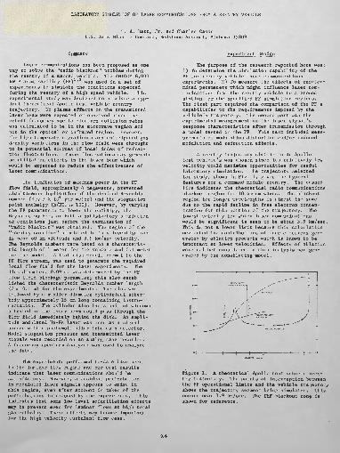
A reentry trajectory similar to an Apollo test vehicle's was chosen since its relatively low velocity would maximize opportunities for useful laboratory simulation. The trajectory selected for study, shown in Fig. 1, gives the typical features for a command module reentry. The dashed line indicates the theoretical radio communications blackout region for 10 cm em waves. The blackout region for longer wavelengths is almost the same due to the rapid decline in free electron concen tration for this portion of the trajectory. The lowest velocity for which laser communications would be significant is seen to be about 3.9 km/sec. This is not a lower limit because this calculation neglected the contributions of free electrons gen erated by ablation products which is known to be important at lower velocities. Effects of ablation were neither considered in this analysis nor gen erated by the nonablating model.
Figure 1. A theoretical Apollo test vehicle reen try trajectory. The points of interception between the PF operational limits and the vehicle trajectory shows the trajectory segment being simulated. This occurs near 3.9 km/sec. The UHF blackout zone is shown for reference.
9.4-1
The PF's capability range is also indicated in Fig. 1. This capability region is based on the approximation that the flow enthalpy, %vs , is one- half of the total enthalpy. Experimental evidence indicates this to be a useful and valid approxi mation when used for determining the limits of capability from equilibrium calculations. The lower bound is the power limit of 4 megawatts in the flow field, i.e., %pv3 - 4 MW» when p and v are the free stream density and velocity, respectively. The high and low enthalpy limits are variable to some extent but a specific total equilibrium enthalpy of h/RTQ » 300 is near the maximum available. The low enthalpy limit is undetermined but below h/RTo = 75 many other facilities become useful. In order to satisfy the 3.9 km/sec velocity condition, the specific flow field enthalpy required is h/RTQ = 96.5, therefore, the total specific equilibrium en thalpy must be approximately h/RT0 = 200.
The simulation parameter chosen for these experiments was the Reynolds number. This choice was made because the expected effects would be generated by turbulence in the boundary layer next to a laser "porthole" in the reentry vehicle. The free flight environment was used to calculate a set of Reynolds numbers for a characteristic dimen sion of 1 m. These are shown in Table I. Similar calculations were made for one of the highest powered operating conditions available by the PF. In the free flight case the Reynolds number is simply.
Re (1)
where p is the density in kg/m3 , v is velocity in m/sec, I is the characteristic length in meters, and u is the kinematic viscosity in m /sec. Kinematic viscosity was read directly from tabu lated values3 . For the PF environment, a slightly different version of the Reynolds number equation was used. Here
Re p v (2)
where JLL is the viscosity in kg/m sec. The viscosity is calculated from the given expression,
146 T 8 X 10- T + 110
(3)
where T is in degrees Kelvin (°K). The Reynolds number per meter for the PF at a point near the "peak11 on Fig. 1 at 3.9 km/sec is best described in terms of one of the PF's specified operating points. For this example p « 1.8 X 10"4 kg/m3 , v « 3/750 in/sec, and T = 500°K. Viscosity, u, is first calculated from Eq. 3 above. This value of pr, 2,48 X 1Q*"5 kg/m2 sec, combined with the above values of p and v, gives a Reynolds number of 2.78 X 10⁴ per meter. The difference between the PF conditions and the real flight environment would be small if a full size model (or models or vehicle sections) could be used. Velocities are fairly close together,, 3,900 m/sec in the real case and 3,750 m/sec in. the PF.. The facility simulation parameter, the Reynolds number of 3 X 10 per meter, is within, a factor of three of 'matching the 7 X 1C4 per meter required for exact duplication.
TABLE I
REYNOLDS NUMBER PER METER AS A FUNCTION OF THE TRAJECTORY PARAMETERS
Alt. (km)
90 - 60
52
43
40.5
40.5
43
61
39
32
Velocity, (m/sec)
9,350
9,000
8,000
7,000
6,000
5,000
4,000
3,000
2,000
v Kinemat ic Viscosity v (ms /sec)
*3.28'2 to 8.69"2
2.07"2
6.43"3
4.46"3
4.46-3
6.43-3
5.21-2
3.56"3
1.18~3
Reynolds NumberPer Meter
* 10P
4.36s
1,24s
1.576
1.356
7.775
7.864
8.435
1.70s
*Note: Exponents represent powers of 10_______
Equipment Setup
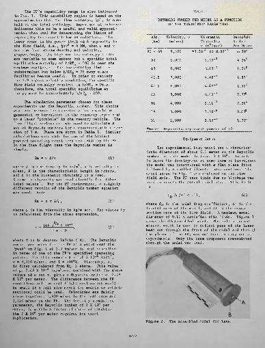
The experimental test model has a character istic dimension of about 0.1 meter so the Reynolds number for this model is about 3 X 10³ . In order to favor the development of some form of turbulence the model was constructed with a flat plate front followed by a smaller diameter base section. The model shown in Fig. 2 was centered on the flow field axis. The PF test limit due to blockage was used to govern the actual model size. This limit is
CD Am/Af < .11, (4)
where CD is the model drag coefficient, Am is the frontal area of the model, and Af is the cross section area of the flow field. A maximum model diameter of 0.11 m satisfies this limit. Figure 3 shows the disassembled model. The half silvered mirror, which is used to deflect part of the laser beam out through the front of the model and through the plenum of the PF, was not used in this set of experiments. Only the beam component transmitted through the model was used.
BFigure 2. The assembled model for laser
9.4-2
tran.smissi.Qin experiments* The model is mountedso the flat disk faces the flow. The central window* A, is a quarts cylinder %' ! diameter by%lf long. The 1/8" hole, B» 'next to the windowis an impact pressure port. The afterbody contains instruiien.tat.ioii. incidental to the operation of the PF.
6. The ac output signal of the photomultiplieris then fed into an oscilloscope or/and a loop tape recorde r for eventua 1 fre que ncy spect rum wave a.na 1 y s is, When the data is read out on the oscilloscope, ampli tude of the modulation envelope vs. time is measured. When the wave analyzer is used, the amplitude of the various frequency components is measured and aver aged 'Over the measurement time. Figure 5 shows a photograph of the model being tested in the PF.
B
nMODEL
FILTER,, 3TOP A..C DETECTOR
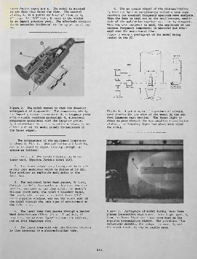
Figure 3. The model opened to show the interior arrangement of components. The components are A, the impact pressure transducer; B, a Langinuir probe with, variable position mechanism; C, electronic components associated with the Langmuir probe; D, a vibration meter. The sapphire windows, E, on either side of the model permit transmission of the laser signal.
The arrangement of the equipment components is shown in Fig. 4. Data collection and handling can be followed by signal tracing through the system as follows:
1. An rf, 40 MHz exciter drives the He-Ne laser used, (Spectra Physics Model 115).
2. The laser output goes through an interfer ometer type modulator which is driven at 20 kHz. This produces an amplitude modulation on the laser beam.
3. The modulated laser beam passes, in turn, through the PF's observation window into the test section, one side of the flow field, the model's oblique shock wave, the model's boundary layer, the model, via the portholes which have 1/16" thick sapphire windows, and out the other side of the model through the same type of environment as the inlet side.
4. The laser beam then passes through a narrowband interference filter (AX #« 1.5 (J,m) and, if required, one or more "grey" attenuation filters,and an iris diaphragm stop.
5. The laser beam with any interference effects is then detected by a photomultipHer tube.
Figure 4. Block diagram, of experimental circuit used showing the top view of the model in the six foot diameter test section. The laser light is shown to pass through the two sapphire transmission windows, the boundary layer and shock wave about the model.
Eigure 5. Photograph of model during laser beam plasma interaction experiment. Note light spot, A, from the laser light scattered from dust on the sapphire transmission window. Two prominent flow structural details, the stagnation zone, B, and the shock front, C, may be easily seen.
9.4-3

Data and Analysis
The oscilloscope data serves a valuable qual itative check on the frequency spectrum analyzer results, Deductions based on qualitative spectrum analyzer data were supported by these oscilloscope data. Each experiment required the measurement of the effects from each potential source of interfer ence separately. The combined effects including those from the PF flow field were then obtained, With all laser equipment operating, pretest oscil loscope photographs were 'made which verified that signals were being transmitted through the system. Next oscilloscope photographs were 'made under identical analytical test conditions but with various functions of the PF in operation. Minor adjustments in equipment setup were required, e, g •, t o e 1 im ina t e a v ib r at io n t ran s mi s s io n t o the laser when the PF's cooling water pumps were operating. Also,,, it was shown that the PF's capacitor discharge type ignition starter had no influence on the laser signal read by the photo- mm, 11 ip 1 i e r t ube. F i gur e 6 sh ow s t he mo d u 1 a t i on envelope with only the laser equipment on, and Fig, 7 shows the laser signal oscilloscope record with the PF in operatlorn, The laser signal modu lation envelope indicates the start of operation by the large transient near the left margin, The periodic fo 3 Hz) modulations following start-up are related to the power controller equipment frequency as modified by the electrical effects from the main power generators for the PF. By the end of the second second of operation the starting transients have danped almost to zero and the true plasma interference may be seen,. This interference, although weak, is clearly seem as the noisy edge riding on the modulation envelope.
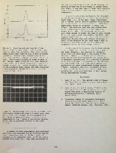
Figure 6. Oscilloscope trace of the photomul- tiplier tube 20 kc output light signals before a test. The time scale is 1 sec/div.
Figure 7. Oscilloscope trace of the photomulti- plier tube 20 kHz output light signals during a test. The time scale is 1 sec/div. The small dc level displacement during the 4% sec test and the noise modulating the signal after the controller settles down is discernible from the photograph.
Quanitative analysis of the frequency content was made with the spectrum analyzer. This shows essentially the same effect as seen in the oscillo graphs. Due to limited running time, only a small portion of the available spectrum was analyzed during each test. The frequency spectrum analyzer was fed signals from the loop recorder after the run for more complete analysis. The range of detailed spectrum analysis was between 19 kHz and 21.5 kHz. This is centered about the modulation frequency but is far above the mechanical vibration frequency or even the flow field turbulence frequency. Results obtained from this study of the present data indicates: a) A low frequency noise superimposed on the modulation envelope, and b) a high frequency component added near the modulation frequency. The spectrum analyzer output is shown in Fig. 8. The way in which these additional frequencies modify the laser beam has not. been determined at present. A suitable mechanism having the necessary nonlinear- ity to couple energy directly into the laser elec tromagnetic wave has not been visualized. The laser frequency and the modulation frequency are both very far from the plasma cutoff frequency. A portion of the noise is attributed to the low but finite radiation from the plasma around the model.
A second set of experiments was performed to measure the effect of plasma radiation on the laser detector output. In this case all laser equipmentwas turned on and laser signal transmission andsystem signal gain were checked. Then, with the laser beam's being physically blocked before itentered the PF's window, the detector output was 'measured on an oscilloscope while the PF was operated. Figure 9 shows the effects obtained. To determine the quanitative contribution of this noisesource to the laser communications signal wouldrequire a series of tests having adjustments in the filter transmission band and/or in the spacing between the model and detector.
0,4-4
20,0 20.5 21.0
FREQUENCY (Hz)
Figure 8. Spectrum analyzer records of the photomultiplier tube output light signals taken from the loop tape recorder. Top trace, record taken during test shown in Fig. 6 with no arcjet operation. Bottom trace, record taken during test shown in Fig. 7 during the arcjet operation only. Photocurrent plotted in terms of gain in db. Records taken during PF runs show miscella neous spikes of a few db occurring at apparently random frequencies. Actual frequency structure of the modulated light signal has some occasional noise components blended into it but they are always at low level.
the laser signal occurred with the PF running, 4 portion of this can be attributed to plasma radia tion which, in the real case of laser communications from a reentry vehicle, could be 'made to be of no consequence,
A possible alternate explanation for the modu lation distortion lies in the scintillation of the laser beam, i.e., in the small angle deflections due to thermal and/or density gradient fluctuations in the gas around the reentry vehicle. Additional experiments should be performed to study this effect. The detector used here was covered with an iris diaphragm in front of a collimator to reduce stray light. The diaphragm opening was just large enough to permit the beam to pass through it almost unattenuated when axially centered. Any angular-displacements of the laser beam by density refraction fluctuations will produce shadowing of parts of the detector as the laser beam's axis is modulated which then would generate amplitude modulation in the detector output signal.
During actual field tests, the indirect plasma, effects, those due to radiation from the plasma at the laser frequency, are expected to disappear since these are attenuated by the square of the distance. However, the direct plasma effects, those due to beam axis modulation and signal level or frequency interactions, will continue to persist since they attenuate in proportion to the distance. The conclusion from this study would support the application of laser transmission during reentry flights, neglecting beam axis modulation effects. Definitions of the limits to beam axis modulation problems and their solutions must be made during future experimental studies.
References
1. Barr, T. A., Jr., "The AMICQM 8,000 kW Plasma Facility," Fourth Space Congress, Cocoa Beach, Fla. (April 1967).
2. Barr, T. A., Jr. and C. Cason, "Multiple Arc Performance in an 8,000 k¥ Plasma Facility," Eighth Symposium on Engineering Aspects of Magnetohydrodynamics," Stanford, Calif. (March 1967).
3. "Numerical Tables of Atmosphere Parameters Based on the ARDC Model Atmosphere, 1936," Report No. DA-TN-197, Army Ballistic MissileAgency, Redstone Arsenal, Ala. (February 1958).
Figure 9. Oscilloscope trace of the photomultipliertube output signals but with a blocked laser beam during a PF run. A small dc displacement of a uniform noise modulated output signal is seen. Comparison to Fig, 7 gives a qualitative measure .of the plasma, generated effects on the light signals.
A number of other experiments were performed using the same equipment but at different modula tion frequencies, down to 100 Hz. These all appeared to be compatible with the 20 kHz result already discussed, viz., that distortion of
9.4-5