laboratory tests of chemical reactions and prototype sorption
TRANSCRIPT

Laboratory Tests of Chemical Reactions and Prototype Sorption Storage Units A Report of IEA Solar Heating and Cooling programme - Task 32 Advanced storage concepts for solar and low energy buildings
Report B4 of Subtask B January 2008
Edited by: Chris Bales Contributions from: Paul Gantenbein Dagmar Jaenig Henner Kerskes and Karola Summer Martijn van Essen et al. Robert Weber
Storage Task 32

Laboratory Tests of Chemical Reactions and Prototype Sorption Storage Units
by
Chris Bales (editor)*
Contributions from:
Paul Gantenbein, SPF, Rapperswil, Switzerland, Dagmar Jaenig, AEE-INTEC, Gleisdorf, Austria
Henner Kerskes and Karola Summer, ITW, Stuttgart, Germany Martijn van Essen (et al.), ECN, Petten and TU Eindhoven, Holland
Robert Weber, EMPA, Switzerland
A technical report of Subtask B
* Solar Energy Research Center SERC Högskolan Dalarna SE-78188 Borlänge, Sweden

Executive Summary Five laboratory prototypes of thermochemical and sorption storage are described in this report as well as the material characterisation of a promising chemical reaction with MgSO4.7H2O. Measured results and projected heat storage densities for units of 70 and 1000 kWh storage for single family houses are reported. Four of the five prototypes are closed sorption units and act as thermally driven heat pumps. Two work with absorption: three phase absorption process, Thermo Chemical Accumulator (TCA) with Lithium Cloride/water, and two phase absorption with Sodium Hydroxide/water. Two work with adsorption, one with zeolite and the other with silica gel. The fifth prototype that is reported, Monosorp, uses an open adsorption process integrated into a standard ventilation system with heat recovery. The different technologies are at very different stages of development. The TCA technology is in the process of commercialisation by the Swedish company ClimateWell AB, and over 35 storage systems have been delivered, mostly in Spain. The other technologies are in the prototype stage with no companies intending to develop and market them. The Modestore store (silica gel /water) was developed in a European project, and the main company within the project (Sortech) is commercialising the technology as a heat pump with essentially no heat storage.
The storage density for cold (based on total system volume), when compared to water, is more favourable than for heat. For the ClimateWell 10 commercial heat pump/store, the storage density for cold is 4.7 that of water whereas for heat it is only 1.2 times greater. This is due to the fact that the temperature range available for water storage for cold is much smaller (~10°C) than for heat (~60°C).
For short term heat storage, the best technologies have an energy density 2 – 2.5 times that of water. This is relatively low due to the space required for reactors and condenser/evaporator in addition to the store. In addition all of the storage systems have irreversibilities in the processes themselves during charge and discharge resulting in lower store efficiencies.
For longer term storage (1000 kWh) the energy density for the TCA technology and NaOH storage systems is nearly three times that of water, for Monosorp twice and for MgSO4.7H2O 2.5. In addition, once the sensible heat from the solution has been lost (or at best recovered), the energy can be stored indefinitely, a significant advantage compared to water. In terms of material cost, all materials are expensive compared to water. However, NaOH, is significantly less expensive than the other materials reported: zeolite, LiCl, silica gel, MgSO4.7H2O and zeolite 13X. The cost for the whole storage system has not been estimated here. For the ClimateWell 10, the projected cost is ~8000€ for a heat pump system consisting of two units in parallel, with a total heat storage capacity of 70 kWh.
The work reported here shows that significant advances have been made in terms of chemical and sorption storage. New concepts have been developed, not only to the laboratory prototype stage but even to successful field trials. Short term sorption storage for cooling using the thermochemical accumulator process is on the verge of full commercialisation while the Monosorp project has shown that an open adsorption process can potentially provide long term storage in relatively simple systems with current materials. Work in Holland with systematic, long term studies on materials for seasonal storage of solar heat point the way to an interesting future in the field. Further, long term research is required in order to realise the full potential of solar energy for heating and cooling.
IEA SHC – Task 32 – Advanced storage concepts

IEA Solar Heating and Cooling Programme
The International Energy Agency (IEA) is an autonomous body within the framework of the Organization for Economic Co-operation and Development (OECD) based in Paris. Established in 1974 after the first “oil shock,” the IEA is committed to carrying out a comprehensive program of energy cooperation among its members and the Commission of the European Communities. The IEA provides a legal framework, through IEA Implementing Agreements such as the Solar Heating and Cooling Agreement, for international collaboration in energy technology research and development (R&D) and deployment. This IEA experience has proved that such collaboration contributes significantly to faster technological progress, while reducing costs; to eliminating technological risks and duplication of efforts; and to creating numerous other benefits, such as swifter expansion of the knowledge base and easier harmonization of standards. The Solar Heating and Cooling Programme was one of the first IEA Implementing Agreements to be established. Since 1977, its members have been collaborating to advance active solar and passive solar and their application in buildings and other areas, such as agriculture and industry. Current members are: Australia Finland Portugal Austria France Spain Belgium Italy Sweden Canada Mexico Switzerland Denmark Netherlands United States European Commission New Zealand Germany Norway A total of 39 Tasks have been initiated, 30 of which have been completed. Each Task is managed by an Operating Agent from one of the participating countries. Overall control of the program rests with an Executive Committee comprised of one representative from each contracting party to the Implementing Agreement. In addition to the Task work, a number of special activities—Memorandum of Understanding with solar thermal trade organizations, statistics collection and analysis, conferences and workshops—have been undertaken.
IEA SHC – Task 32 – Advanced storage concepts

The Tasks of the IEA Solar Heating and Cooling Programme, both underway and completed are as follows: Current Tasks: Task 32 Advanced Storage Concepts for Solar and Low Energy Buildings Task 33 Solar Heat for Industrial Processes Task 34 Testing and Validation of Building Energy Simulation Tools Task 35 PV/Thermal Solar Systems Task 36 Solar Resource Knowledge Management Task 37 Advanced Housing Renovation with Solar & Conservation Task 38 Solar Assisted Cooling Systems Task 39 Polymeric Materials for Solar Thermal Applications Completed Tasks: Task 1 Investigation of the Performance of Solar Heating and Cooling Systems Task 2 Coordination of Solar Heating and Cooling R&D Task 3 Performance Testing of Solar Collectors Task 4 Development of an Insolation Handbook and Instrument Package Task 5 Use of Existing Meteorological Information for Solar Energy Application Task 6 Performance of Solar Systems Using Evacuated Collectors Task 7 Central Solar Heating Plants with Seasonal Storage Task 8 Passive and Hybrid Solar Low Energy Buildings Task 9 Solar Radiation and Pyranometry Studies Task 10 Solar Materials R&D Task 11 Passive and Hybrid Solar Commercial Buildings Task 12 Building Energy Analysis and Design Tools for Solar Applications Task 13 Advance Solar Low Energy Buildings Task 14 Advance Active Solar Energy Systems Task 16 Photovoltaics in Buildings Task 17 Measuring and Modeling Spectral Radiation Task 18 Advanced Glazing and Associated Materials for Solar and Building Applications Task 19 Solar Air Systems Task 20 Solar Energy in Building Renovation Task 21 Daylight in Buildings Task 23 Optimization of Solar Energy Use in Large Buildings Task 22 Building Energy Analysis Tools Task 24 Solar Procurement Task 25 Solar Assisted Air Conditioning of Buildings Task 26 Solar Combisystems Task 28 Solar Sustainable Housing Task 27 Performance of Solar Facade Components Task 29 Solar Crop Drying Task 31 Daylighting Buildings in the 21st Century Completed Working Groups: CSHPSS, ISOLDE, Materials in Solar Thermal Collectors, and the Evaluation of Task 13 Houses To find Solar Heating and Cooling Programme publications and learn more about the Programme visit www.iea-shc.org or contact the SHC Executive Secretary, Pamela Murphy, e-mail: [email protected] September 2007
IEA SHC – Task 32 – Advanced storage concepts

What is IEA SHC Task 32 “Advanced Storage Concepts for solar and low energy buildings” ?
The main goal of this Task is to investigate new or advanced solutions for storing heat in systems providing heating or cooling for low energy buildings.
o The first objective is to contribute to the development of advanced storage solutions in thermal solar systems for buildings that lead to high solar fraction up to 100% in a typical 45N latitude climate.
o The second objective is to propose advanced storage solutions for other heating or cooling technologies than solar, for example systems based on current compression and absorption heat pumps or new heat pumps based on the storage material itself.
Applications that are included in the scope of this task include:
o new buildings designed for low energy consumption o buildings retrofitted for low energy consumption.
The ambition of the Task is not to develop new storage systems independent of a system application. The focus is on the integration of advanced storage concepts in a thermal system for low energy housing. This provides both a framework and a goal to develop new technologies.
The Subtasks are:
o Subtask A: Evaluation and Dissemination o Subtask B: Chemical and Sorption o Subtask C: Phase Change Materials o Subtask D: Water tank solutions
Duration
July 2003 - December 2007.
www.iea-shc.org look for Task32
IEA SHC – Task 32 – Advanced storage concepts

IEA SHC Task 32 Subtask B “Chemical and Sorption Storage” This report is part of Subtask B of the Task 32 of the Solar Heating and Cooling Programme of the International Energy Agency dealing with solutions of storage based on adsoprtion or absorption processes and on thermochemical reactions. The density of storage for these techniques compared to that of water is theoretically 2 to 10 depending on the temperature range of comparison. The topic of storing energy in an absorption process is not new. For cooling purposes at least it has been exploited for decades. A new technology from Sweden, a three phase system both for cooling and heating purposes is, however, recent and was studied within Task 32. Adsorption techniques on silicagel or zeolite materials, long time forgotten for solar energy, have been investigated in Task 32. Results are presented in this document. Chemical reactions deserve much more effort than the one Task 32 could raise. Unfortunately despite its huge potential very little research money has been invested in this topic for decades. We hope Task 32 has helped to re-open this way of storing solar energy in a dense manner. The report does not cover all aspects of the targeted topic of a Subtask since the rules of an IEA SHC Task is that participating countries share information on projects they decide to bring in the Task. Projects presented in this report reflects the knowledge of the participating body presenting the project. The Operating Agent would like to thank the authors of this document for their implication in the search of future storage solutions for solar thermal energy, the key to a solar future for the heating and cooling of our buildings.
Jean-Christophe Hadorn Operating Agent of IEA SHC Task 32 for the Swiss Federal Office of Energy BASE Consultants SA - Geneva [email protected]
NOTICE: The Solar Heating and Cooling Programme, also known as the Programme to Develop and Test Solar Heating and Cooling Systems, functions within a framework created by the International Energy Agency (IEA). Views, findings and publications of the Solar Heating and Cooling Programme do not necessarily represent the views or policies of the IEA Secretariat or of all its individual member countries.
IEA SHC – Task 32 – Advanced storage concepts

Contents
1 INTRODUCTION 1
1.1 Definitions 2
2 PROTOTYPE STORAGE UNITS AND TEST RESULTS 3
2.1 TCA Heat Pump and Storage Unit ClimateWell 10 3
2.1.1 Background 3
2.1.2 Design and Operating Principles 3
2.1.3 Laboratory Test Results 4
2.1.4 Development Status 6
2.1.5 Acknowledgements 7
2.1.6 References 7
2.2 Sorption storage unit with Zeolite (Silicagel) / water 8
2.2.1 Background 8
2.2.2 Operating Principles and Design 8
2.2.3 Laboratory Test Results 9
2.2.4 Development Status 14
2.2.5 Acknowledgements 14
2.2.6 References 15
2.3 Solid Sorption Storage System (MODESTORE) 16
2.3.1 Background 16
2.3.2 Design and Operating Principles 16
2.3.3 Laboratory Test Results 18
2.3.4 Development Status 21
2.3.5 Acknowledgements 21
2.3.6 References 22
2.4 NaOH Storage 23
2.4.1 Background 23
2.4.2 Design and Operating Principles 23
2.4.3 Laboratory Test Results 24
2.4.4 Development Status 25
2.4.5 References 25
IEA SHC – Task 32 – Advanced storage concepts

2.5 Characterization of magnesium sulphate as thermo chemical material for seasonal heat storage 26
2.5.1 Background 26
2.5.2 Design and Operating principle 26
2.5.3 Laboratory test results 27
2.5.4 Development Status 35
2.5.5 Acknowledgements 36
2.5.6 Literature 36
2.6 Open Adsorption System with Zeolite 37
2.6.1 Background 37
2.6.2 Design and Operating principle 37
2.6.3 Laboratory test results 38
2.6.4 Development status 41
2.6.5 Acknowledgements 42
2.6.6 Literature 42
3 COMPARISON OF PROTOTYPES 43
4 CONCLUSIONS 46
IEA SHC – Task 32 – Advanced storage concepts
1
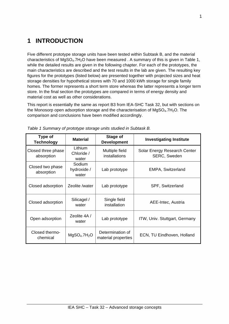
1 INTRODUCTION Five different prototype storage units have been tested within Subtask B, and the material characteristics of MgSO4.7H2O have been measured . A summary of this is given in Table 1, while the detailed results are given in the following chapter. For each of the prototypes, the main characteristics are described and the test results in the lab are given. The resulting key figures for the prototypes (listed below) are presented together with projected sizes and heat storage densities for hypothetical stores with 70 and 1000 kWh storage for single family homes. The former represents a short term store whereas the latter represents a longer term store. In the final section the prototypes are compared in terms of energy density and material cost as well as other considerations.
This report is essentially the same as report B3 from IEA-SHC Task 32, but with sections on the Monosorp open adsorption storage and the characterisation of MgSO4.7H2O. The comparison and conclusions have been modified accordingly.
Table 1 Summary of prototype storage units studied in Subtask B.
Type of Technology Material Stage of
Development Investigating Institute
Closed three phase absorption
Lithium Chloride /
water
Multiple field installations
Solar Energy Research Center SERC, Sweden
Closed two phase absorption
Sodium hydroxide /
water Lab prototype EMPA, Switzerland
Closed adsorption Zeolite /water Lab prototype SPF, Switzerland
Closed adsorption Silicagel / water
Single field installation AEE-Intec, Austria
Open adsorption Zeolite 4A / water Lab prototype ITW, Univ. Stuttgart, Germany
Closed thermo-chemical MgSO4.7H2O Determination of
material properties ECN, TU Eindhoven, Holland
IEA SHC – Task 32 – Advanced storage concepts

2
1.1 Definitions The following terms used in this report are defined here. Energy density of the material is often dependent on the operating conditions of the unit in which the material is used. This is defined together with storage density for each of the units. The relevant key figure as defined in the report A1 of IEA-SHC Task 32 is given in parentheses. Energy density of the material (NRJ4.1) This is the ratio of the storage capacity to the volume of the active substance when fully loaded with water in the case of sorption, or combined with the other substance in the case of other chemical reactions. In this context fully loaded means in terms of the design operating conditions of the prototype store and not the theoretical maximum of the material. During operation the store will not always operate over the full range of loading under all conditions. This value indicates the maximum value expected during normal operation and not an average value. Energy density of prototype store (NRJ4.2) This is the ratio of the storage capacity to the volume of all storage vessels required in the prototype unit including pipes for transfer between the various vessels and including any separate vessels for heat exchange. This represents the practical heat storage density in the prototype storage and is again related to the maximum storage during normal operation, and not an average. Floor space required This is the “footprint” of the storage unit including all vessels, valves and pumps necessary for its operation. Relative density compared to water This is the ratio of the storage capacity of the prototype store to that of an equivalent water store used in the temperature range 25-85°C (69.2 kWh/m3), unless otherwise stated. Estimated size for 70 / 1000 kWh store This an estimate of the size that the storage unit would have, including all parts necessary for the same design charging rate and load as the prototype, if it were to have a storage capacity of 70 or 1000 kWh – for the same conditions and performance as the prototype. Charge / Discharge Rate These are the design charge / discharge rates for the prototype and are a measure of the heat exchange transfer rather than the storage capability. They should be the maximum values, but if this maximum value is only valid for part of the time, then a range is given. Boundary Conditions The boundary conditions are given for all relevant parameters such as temperature, degree of loading and heating rates.
IEA SHC – Task 32 – Advanced storage concepts

3
2 PROTOTYPE STORAGE UNITS AND TEST RESULTS
2.1 TCA Heat Pump and Storage Unit ClimateWell 10 Chris Bales, SERC, Högskolan Dalarna, Sweden
2.1.1 Background The thermo-chemical accumulator (TCA) is an absorption process that uses a working pair, not only in the liquid, vapour and solution phases but also with solid sorbent [1], and was patented in 2000. This makes it significantly different from the traditional absorption processes in that it is a three phase process (solid, solution and vapour). All other absorption processes are two phase processes with either solution + vapour or solid + vapour.
The TCA technology has been developed principally for cooling applications but it will also be used for space heating during winter in certain applications. The first prototypes had serious problems with reliability, which seem to have been solved in the generation of prototypes that have been working for over 6 months without need for maintenance or vacuum pumping. The third generation prototypes have been tested only by the developing company (ClimateWell AB) at there in house test rig under the supervision of SERC. The flow rates in the external circuits was lower than those that the unit is designed for, resulting in abnormally high temperature differences between inlet and outlet, especially on the condensor/evaporator. The presented results are based on measurements made in November 2005 on an industrial prototype that was soon after installed in a system in Spain. Analysis of the results showed errors in one of the four circuits (charging circuit) so the energy quantities had to be estimated based on the electrical heating rate in the circuit and estimated losses. The tests were performed in order to calculate the COP of the unit for use in a cooling application.
2.1.2 Design and Operating Principles The basic process is a batch process, with separate charge (desorption) and discharge (absorption) phases. Figure 1 shows the schematic of a TCA unit, where the solution is pumped over a heat exchanger in the reactor via a spreader to increase the wetted area and improve heat transfer. Water is desorbed from the solution during charging and the solution comes closer and closer to saturation. When it reaches saturation point further desorption at the heat exchanger results in the formation of solid crystals that fall under gravity into the vessel. Here they are prevented from following the solution into the pump by a sieve, thus forming a form of slurry in the bottom of the vessel.
For discharging, where the process is reversed, saturated solution is pumped over the heat exchanger where it absorbs the vapour evaporated in the evaporator. The heat of evaporation is provided either by the building (cooling mode) or from the environment (heating mode). The solution becomes unsaturated on the heat exchanger, but when it falls into the vessel it has to pass through the slurry of crystals, where some of the crystals are dissolved to make the solution fully saturated again. In this way the solution is always saturated and the net result is a dissolving of the crystals into saturated solution. The heat of condensation and binding energy release is transferred to the environment (cooling mode) or to the building (heating mode).
IEA SHC – Task 32 – Advanced storage concepts

4
More details can be found in [2] and [3].
The TCA the following characteristics:
High energy density storage in the solid crystals.
Good heat and mass transfer, as this occurs with solution.
Solution vessel
Water vessel
Reactor
Condensor / Evaporator
Figure 1. TCA store, third generation (CW10), with schematic (left) and during installation in the test rig (right).
2.1.3 Laboratory Test Results The test results from the lab measurements and calculations based on these are summarised in Table 2. These show that the energy storage for one prototype unit of the TCA, when operated as for a cooling application is approximately 35 kWh heat, and 22 kWh cooling energy. This is the equivalent of an energy density for the material, LiCl salt, of 253 kWh/m3 or 3.6 times that of water (25 - 85°C). This could be increased if the solution was used over a larger concentration range, but this has been restricted by the control algorithm for the cooling applications that the unit is designed for. Due to the physical design of the unit, with the necessary heat exchangers, pipes and stores for solution and water, it is only 1.2 times that of water when these are included. This improves to a factor 1.6 if a store of 70 kWh is used and to 2.7 for a store for 1000 kWh.
IEA SHC – Task 32 – Advanced storage concepts

5
Table 2. Test results a single unit of a third generation TCA prototype. All figures based on test results for two full cycle measurements carried out at ClimateWell AB, November 2005. Conditions relevant for cooling application.
Parameter Measured Performance Boundary Conditions
Storage materials weight: LiCl salt Water Steel
54 kg
117 kg 47 kg
Storage capacity for heat 35 kWh At charging / discharge rates (below)Floor space required for prototype 0.46 m2 Energy density of material (NRJ4.1) (ratio to water 25/85°C)
253 kWh/m3
(3.6)
Energy density of prototype - heat (NRJ4.2) (ratio to water 25/85°C)
85 kWh/m3
(1.2) Based on short term storage
Energy density of prototype - cold (ratio to water 7/17°C)
54 kWh/m3
(4.7) Based on cooling energy that can be extracted and comparison to cold water storage
Charge rate 15 kW 13/25°C to/from condensor 46 – 87°C to reactor during charge
Discharge rate 8 kW 21/12°C to/from evaporator 25°C constant inlet temperature to reactor, ~30°C outlet
Estimated size for 70 kWh (ratio to water 25/85°C)
0.64 m3
(1.6) A pure scaling up of prototype with same size for reactor and condensor, but increased store sizes
Estimated size for 1000 kWh (ratio to water 25/85°C)
5.29 m3
(2.7) Assumes same size for reactor and condensor, scaled up solution and water stores.
Cost of solution (same volume as energy density)
3600 €/m3
Figures 2 and 3 show the charging and discharging profiles from the lab measurements respectively. The charging temperature range is from 40 - 85°C for the charging rate of 15 kW (estimated). The inlet temperature to the condensor, which controls quite directly the required charging temperature, was held constant at approximately 13°C. The flow rate through the condensor/evaporator was very low resulting in high temperature rises over the heat exchanger that adversely affects performance and temperature lift. This can be seen in Figure 3. During discharge the inlet to the reactor was kept constant at 25°C, the outlet (heating supply) temperature being thus dependent on this and the heating rate, being roughly 30°C for most of the measurement. The high discharge rate at the start of the discharge is mainly from sensible cooling of the solution and water, the heat pumping only starting after some 10 minutes.
IEA SHC – Task 32 – Advanced storage concepts

6
0
20
40
60
80
100
2005-11-2208:38
2005-11-2209:36
2005-11-2210:33
2005-11-2211:31
2005-11-2212:28
Time
Tem
pera
ture
[°C
]
0
10
20
30
40
50
Hea
t Tra
nsfe
r Rat
e [k
W]
Tcg,iTcg,oTcond,iPcg
Figure 2. Charge profile for the laboratory tests used to compile data for Table 2.
0
20
40
60
80
2005-11-22 10:33
2005-11-22 11:31
2005-11-22 12:28
2005-11-22 13:26
2005-11-22 14:24
2005-11-22 15:21
2005-11-22 16:19
Time
Tem
pera
ture
[°C
]
0
20
40
60
80
Hea
t Tra
nsfe
r Rat
e [k
W]
Theat,iTheat,oTevap,iTevap,oPheatPsource
Figure 3. Charge profile for the laboratory tests used to compile data for Table 2.
2.1.4 Development Status The TCA technology is still under development and should be considered as a relative recent invention. The company developing it is focussing on the solar cooling market, with some winter cooling, as well as to a certain extent on tri-generation systems. There are no plans for developing the technology as a purely heat storage device, although the integral heat/cold storage is used in the solar cooling applications where no external cold or hot store is required as long as the load is not too large during the night. Commercialisation of the technology for cooling applications is in progress, with some 11 M€ of risk capital being invested. Most effort is going towards rational serial production, but significant effort is being used for system and control development, improved performance and also to investigations of alternative salts.
IEA SHC – Task 32 – Advanced storage concepts

7
2.1.5 Acknowledgements The work reported here has been financed by the Swedish National Energy Agency through the projects P21241-1 and P21543-1.
2.1.6 References 1. Olsson, R., M. Kaarebring-Olsson, and S. Jonsson, A Chemical Heat Pump, in World
Patents Register. 2000.
2. Bales, C. and S. Nordlander SERC report ISRN DU-SERC--91--SE: TCA EVALUATION - Lab Measurements, Modelling and System Simulations, SERC, Högskolan Dalarna, Borlänge, Sweden.www.serc.se. 2005.
3. Hadorn, J.-C., ed. Thermal Energy Storage for Solar and Low Energy Buildings .- State of the Art. 2005, Lleida University: Lleida, Spain. ISBN: 84-8409-877-X.
IEA SHC – Task 32 – Advanced storage concepts

8
2.2 Sorption storage unit with Zeolite (Silicagel) / water Paul Gantenbein, Institut fuer Solartechnik SPF, HSR Hochschule fuer Technik, Oberseestrasse 10, CH-8640 Rapperswil.
2.2.1 Background In the adsorption process the heat of adsorption ∆hA = ∆hv + ∆hB (heat of evaporation ∆hv; binding energy ∆hB) is released and the combined solid sorbent plus the adsorbed sorbate are heated up [1-3]. Because the theoretical energy density of water vapour adsorbed on Zeolite is in the range of 180 kWh/m3, the size of a water storage tank could be significantly reduced. While the measurements of the heat of adsorption ∆hA of water vapour on Zeolite and Silicagel are nearly confirming these values [2], in the sorption storage system design, all the losses have to be considered and the temperature levels in the discharge cycle as well as in the charging cycle are of significant importance. But a much more important point is that in case of discharging the storage tank the heat of evaporation ∆hv has to be delivered to the system. So in principle, the storage system is a thermally driven heat pump. The environment or a solar thermal system can be used as the supplying energy source for the heat of evaporation ∆hv. In case of charging the sorption tank i.e. drying the sorbent material, thermal energy sources at temperatures of up to 200 °C for Zeolite and 120 °C for Silicagel are needed. Applying these materials, lower charging temperatures are leading to lower energy outputs of the storage system. As in case of delivering the required heat of evaporation to the system solar thermal vacuum tube collectors can be used to dry the sorbent material.
2.2.2 Operating Principles and Design The operating principles of an open and a closed sorption storage system can be read for example in the papers of HAUER 2000 and MITTELBACH et al 2000, respectively. So, the following explanations focus on the planning and experimental work done at SPF. The power P of a sorption storage system is directly correlated with the uptake of water vapour c(T, p) by the sorption material as a function of time t multiplied by the heat of adsorption ∆hA(c): P ~ dm/dt(c, T) * ∆hA(c, T). And the total energy is the integration with respect to the time t. Because all the power P determining variables are functions of the temperature T and the pressure p [4] the temperature level at which the process will run is very important. With the aim to design an efficient storage system, an experimental set-up to measure the speed of adsorption dm/dt of water vapour on Zeolite and Silicagel and the temperature development in the fixed bed of solid sorbent material was built. The findings will help to understand how the process behaves and assist with the design of an efficient sorption module heat exchanger, which is one of the key components of the system. Measurements in a Laboratory sorption unit with a new rib heat exchanger immersed in the solid, spherical shaped sorption material were made.
In Figure 4 the experimental set-ups are shown schematically. On the left the unit for measuring the adsorption speed dm/dt of water vapour on Zeolite and on Silicagel in function of time t is shown, [5]. And on the right of Figure 4 a schematic of the sorption system with the new rib heat exchanger for measuring the power output is shown. Spherical Zeolite 13 X particles with an average diameter of 1 mm and granular Silicagel 490 with a particle size distribution of 3 – 5 mm were used as sorbent materials. The bulk densities are 650 kg/m3 for Zeolite 13 X and 470 kg/m3 for Silicagel 490. The BET surface of
IEA SHC – Task 32 – Advanced storage concepts

9
Zeolite 13 X is in the range of 500 m2/g and 800 m2/g and for Silicagel 490 it is 400 m2/g [6, 7]. Zeolite 13 X and Silicagel 490 have an average pore size of 1 nm and 9 nm, respectively. In humid air the water uptake c(p, T) of the two different sorbent materials is approximately 25 wt. % and 80 wt. % for Zeolite 13 X and Silicagel 490, respectively. The sorbent material fixed bed was dried at a temperature of T = 100 °C by the electrical heating and simultaneous pumping with the turbo-molecular and the mechanical vacuum pumps. The temperature T(t, z) and weight m(t) increase was measured in fixed beds of Zeolite 13 X and Silicagel 490 adsorbing water vapour of different vapour pressures p(T) and temperatures T, respectively. Power output measurements with the new rib heat exchanger immersed in the solid sorption material were only made with spherical shaped Zeolite 13 X particles of 1 mm average diameter, Figure 4 right.
ZM MF
TI
GI(T2)
LI
TI
TI
TI
PIGO(T3)
Vacuum
WI(T15)
WO(T14)
on/off
PI
Vacuum
WI WO
ZM
WI
LI
TI
PI Vacuum
TI
TI
TI
Vacuum1
23
45
Water vapour flow
valve (on / off)
electrical heating arm of balance
TI: temperature indicatorPI: pressure indicatorLI: level indicatorWI: weight indicator
ZM: zeolite module
z L
A
Figure 4. Left: Schematic of the experimental set-up with two vacuum chambers to measure time dependent mass adsorption on granular Zeolite and Silicagel and the temperature development as a function of time and position z (1 cm to 5 cm) in the fixed bed (ZM) of solid sorbent material (left). On the right, a schematic of the laboratory sorption unit (with new rib heat exchanger) to measure temperature profiles and power out put is shown. In both schematics the lower chamber contains the sorbate water and the upper chamber the fixed sorbent bed container. Right schematic: PI Pressure Indicator, TI Temperature Indicator, LI Level Indicator, GI Glycol In, GO Glycol Out, WI Water In, WO Water out.
2.2.3 Laboratory Test Results For Silicagel the m(t) data points in Figure 5 show two different ranges separated at the measurement time t i.e. adsorption time t of about t = 300 s at a temperature T = 22 °C in the
IEA SHC – Task 32 – Advanced storage concepts

10
water tank. In both time ranges, from 0 s to t = 300 s and from t = 300 s to t = 3200 s the measured data are fitted with two linear functions. The slope of the first linear curve is dm/dt = 2x10⁻² g/s while the derivation of the second linear curve of dm/dt = 1.7x10⁻³ g/s is more than an order of magnitude smaller. Zeolite 13 X shows similar behaviour but the two time ranges are separated at a time t of t = 400 s and in the first range the adsorbed water vapour per time t is with dm/dt = 3x10⁻² g/s 1.5 times higher than for Silicagel 490. In the second time range the mass adsorption speed is dm/dt = 5x10⁻³ g/s. In Figure 6 the mass m(t) data points as a function of time t are shown for Zeolite 13 X at a temperature T = 22 °C in the water tank.
346
348
350
352
354
356
358
360
362
364
0 500 1000 1500 2000 2500 3000 3500 4000time t [s]
mas
s m
[g]
Silicagel 490
linear function 2: m(t) = a2(m)*t+b2(m)
linear function 1: m(t) = a1(m)*t+b1(m)
measured data
Start of adsorption
Figure 5: Increase of mass as a function of time in the fixed bed of Silicagel 490 by adsorption of water vapour at a pressure of p(H2O, T=22 °C) = 24.8 mbar. In the first t = 300 s the data points can be fitted by a liner function (1) with a slope of dm/dt = 2x10⁻² g/s, while the measured data at a time t > 300 s can be approximated by a liner function (2) with a slope of dm/dt = 1.7x10⁻³ g/s.
375
380
385
390
395
400
405
410
0 500 1000 1500 2000 2500 3000 3500 4000time t [s]
mas
s m
[g]
Zeolite 13 X
linear function 2: m(t) = a2(m)*t + b2(m)
linear function 1: m(t) = a1(m)*t + b1(m)
measured data
Start of adsorption
Figure 6. Increase of mass as a function of time in the fixed bed of Zeolite 13 X by adsorption of water vapour at a pressure of p(H2O, T=22 °C) = 24.8 mbar. In the first t = 400 s the data points can be fitted by a liner function (1) with a slope of dm/dt = 3x10⁻² g/s, while the measured data at a time t > 400 s can be approximated by a linear function (2) with a slope of dm/dt = 5x10⁻³ g/s.
IEA SHC – Task 32 – Advanced storage concepts

11
The dynamic behaviour of Zeolite 13 X and Silicagel 490 under adsorption of water vapour is different. Zeolite 13 X shows a higher water vapour uptake rate than Silicagel 490. Two adsorption speed ranges were identified for Silicagel 490 and Zeolite 13 X. At the beginning of the adsorption process the measured curves m(t) can be approximated by linear functions. The transition from the higher gradient to the lower gradient takes place at an adsorption process time of approximately t = 300 s for Silicagel 490 and t = 400 s for Zeolite 13 X. SAHA 1995, BOELMAN 1995 and BOELMAN 1997 are reporting about operational conditions and coefficient of performance COP of an adsorption refrigeration machine working with Silicagel. The optimum cooling power output is in a cycle time of t = 250 s to t = 300 s while the COP of the machine increases up to COP = 0.5 at a cycle time of t = 1800 s.
For a measurement time t > 1 h the weight m(t) increases as a function of time t for the two sorbent materials Silicagel and Zeolite is again reduced compared to the previous two time ranges. The data for the temperature T(z, t) in function of the position and time t are shown in GANTENBEIN 2006.
A solution of the mass balance equation in the bulk of the fixed bed and in a particle is shown in Figure 7 right. The qualitative curves are calculated with a parabolic concentration profile c(r/Rp) ~ (r/Rp)2, which is according to YANG, 1997 a reasonable assumption. Judging Figure 5, 6 and 7, right and considering the total mass in the experimental fixed bed it can be seen that the maximum concentration c(p, T) of water adsorbed on Zeolite and Silicagel are far from the theoretical in the measured time range. So the 6 g of water on Silicagel 490 and the 12 g of water on Zeolite 13 X in the first 300 s and 400 s are mainly adsorbed in the particles at the inlet to the sorption materials fixed beds (Figure 4 left). Because of the vapour pressure curve p(T, c) of Silicagel and Zeolite, the higher system temperature limits the water uptake c(p, T) at a given pressure [4, 8]. Dunne [9] and Tatlier [10] are therefore reporting and arguing to apply solid sorption material layers for adsorption cooling.
These results have been considered in the design of the heat exchangers immersed in the granular water vapour adsorbing materials. The heat exchangers are the key components of a thermo-chemical energy storage system. Because of the low heat conductivity of Zeolite and Silicagel and the low heat transfer rates in the fixed-bed configuration, a distance of the adsorbing material to the heat conduction surfaces should not be exceeded. This led VAILLANT, 2002 to the construction of a fin tube heat exchanger with a fin distance of one particle diameter. But the high mass relation of the heat exchanger to the sorption material is still resulting in massive thermodynamic penalties.
For these reasons, a rib heat exchanger with nine heat conduction fluid carrying pipes in parallel was built, considering the pressure p and temperature T depending heat transfer coefficients in the bulk of the fixed bed [11, 12]. The distance from one rib to a other was set to d(1) = 7 mm in the x direction and the distance of the pipes was either L = 45 mm in the z direction and L = 60 mm in the y direction. In Figure 7 a schematic of a part of the rib heat exchanger is shown.
IEA SHC – Task 32 – Advanced storage concepts

12
Wat
er v
apou
r flo
wz
L
Ad(1)
h(1)
Water flow
h(2)D
2Rp
0
0.2
0.4
0.6
0.8
1
1.2
1.4
relative distance r/Rp [-]
conc
entra
tion
c(r/R
p, k)
[-]
k = 1
k = 10
k = 100
2Rp
01particle (not to scale)
Figure 7. Schematic of a heat exchanger section with marked parameters (left). The heat exchanger can be either cylindrical or rectangular. On the right hand, a qualitative concentration profile c(r/Rp) in a spherical solid sorption particle depending on the diffusion resistance k during adsorption is shown (right). The particle with a diameter 2Rp as shown is not to scale compared to the concentration profile c(r/Rp). KATO et al 2006 showed an optimum power per volume at a fixed bed height of 4 mm for the CaCl2/CH3NH2 materials combination and a fixed bed height of 7 mm for the system MgO/Water in a chemical heat pump unit.
0.0
10.0
20.0
30.0
40.0
50.0
60.0
70.0
80.0
90.0
0 100 200 300 400 500 600 700 800 900 1000 1100 1200 1300 1400 1500
time t [s]
tem
pera
ture
T [°
C]
T3 [°C] Flow out (GO)
T2 [°C] Flow in (GI)
T14 [°C] Flow out (WO)
T15 [°C] Flow in (WI)
T3 Fit [°C] Flow out (GO)
∆T = 12.7 °C [1800 W]
T = 80.0 °C (T3 Fit)
t = 350 s
∆T = 6.2 °C [800 W]
Figure 8. Typical discharge temperature profile for the sorption unit with the materials combination Zeolite – Water. The temperature curves T2 and T3 are showing the sorption module heat exchanger inlet and outlet temperature of the heat transfer fluid, respectively. The inlet (T15) and outlet temperatures (T14) of the water tank heat exchanger are showing the cooling effect during the sorption process. For comparison the outlet temperature T3 of the sorption module heat exchanger is fitted with an exponential curve (T3 Fit), with the assumption of the temperature increase in the sorption module is similar to the voltage charging curve of a storage capacitance.
First measurements showing the temperature profiles in the sorption unit (Figure 4 right) can be seen in Figure 8. A temperature increase of up to T = 70 °C in the external fluid carrying circuit is reached in the laboratory sorption storage system at a water vapour pressure of p(H2O, T=20 °C) = 23.4 mbar in the water tank. The maximum heating power in sorption
IEA SHC – Task 32 – Advanced storage concepts

13
module reached 800 W at a temperature level T> 55 °C. In the Water tank a maximum cooling power of 1800 W could be measured.
With the prerequisite of the basic physical similarity of thermal and electrical systems a fit to the temperature curve T3 (T3 Fit) was made by applying the exponential behaviour of the capacitance chargeing to the sorption unit. The current sorption module has a time constant of approximately 350 s, which again shows the low heat transfer rates from the Water vapour adsorbing Zeolite to the rib heat exchanger [11, 12].
The energy density of the Zeolite – Water module was determined in function of the Zeolite drying temperature. In table 3 the results are summarized: Table 3: Energy density E in function the heating temperature T.
Heating Temperature T [°C] Energy Density E [kW/m3] 110 33.0 150 54.4 180 57.8
In Table 4 an over view about the results under the experimental conditions is given. Table 4: Summary of the test results.
Parameter Measured Performance
Boundary Conditions
Storage material weight 7 kg Zeolite 13 X Storage capacity for heat 1 kWh T> 55 °C / LaboratoryFloor space required for prototype1 0.3 x 0.3 m2 No flanges – welded Energy density of material (NRJ4.1) (ratio to water 25/85)
180 kWh/m3
(~ 3) No temperature level
specified Energy density of prototype (NRJ4.2) (ratio to water 25/85)
57.8 kWh/m3
(~ 1) Related to the
sorption module (180 °C / 20 °C)
Charge rate - - Discharge rate heating / cooling [kW] 0.8 kW / 1.8 kW 180 °C / 20 °C Estimated size for 70 kWh (ratio to water 25/85)2
1.2 m3
(~ 1) Heat and mass
transfer are the sameEstimated size for 1000 kWh (ratio to water 25/85)2
17 m3
(~ 1) Scale up possible
Cost for material 2-3000 €/m3 Dependent on quantity
1 Related to the sorption module in the upper tank shown in Figure 4 right and that all flanges are replaced by a
welding seam. 2 These values are estimated and provided that the scaling up to a sorption system of the assumed size is
possible. The drying temperature of T = 180 °C for Zeolite is reached under laboratory conditions with an electrical heater and will not be easily reached by solar collectors at a reasonable power.
IEA SHC – Task 32 – Advanced storage concepts

14
But on the other hand if the temperature level in the Water tank is increased the power output and the energy density will be increased [5].
2.2.4 Development Status To measure the adsorption speed of water vapour on the sorbent materials the experiments were done without cooling the fixed bed and so the sorption materials reached a steady state at an equilibrium temperature Tequ that is higher than in case of cooling the sorbent material. By cooling the fixed bed to a temperature level lower than the equilibrium temperature T1 < Tequ in the adsorption process, the load c(T, p) with water vapour will be higher, c(T1, p) > c(Tequ, p) for Tequ > T1, and so the power will be increased. While this was the case in the experiments of which data are shown in Figure 8 the measurement of the speed of adsorption could not be performed in parallel and so the relation between the temperature T of the sorption material and the power of the laboratory sorption unit is unknown.
Nevertheless, various questions remain to be answered. For instance: Is the mass transfer zone travelling with a constant speed through the fixed bed independent of the depth z? Or, is there a limit in the length L because of the water vapour pressure drop while it is flowing through the granular material and the maximum pressure available is the water vapour pressure p(T)? What is the optimum particle size distribution to a constant flow i.e. a constant power density? But the key question is raised by the observed transition from a high to a low speed of adsorption at a time of 6 to 7 minutes. Is the adsorption process of water vapour on Zeolite or Silicagel diffusion limited and such systems working on the basis of the heat pump principle are more suitable for either cooling application and/or – as the working principle suggests – for heat pump application with short cycle time and not for long cycle time heat storage?
Thermal energy storage in a sorption storage system is depending on the available thermal energy sources and sinks. So, the selection of the sorbent – sorbate material combination has to be done under these general conditions, beside of others. With the idea of the reduction of moving parts i.e. pumps in a solid sorption system the power limiting low heat transfer coefficients are leading to a layer structure in the sorption module. But a layer structure applied to a heat exchanger will limit the energy output of the system. In a comparison of the solid adsorption and a the liquid absorption processes the liquid system could be favoured for storage application – exactly because the fluid can be pumped from one storage tank through a reaction zone to an other storage tank. One focus for further development in this technology field has to be kept on new materials – like ionic liquids or functional adsorption materials (H. Kakiuchi, Mitsubishi Chemical Group) – which will have a higher sorption mass ratio in the temperature range reachable by solar thermal collectors. The future work will be dealing with analysing the speed of adsorption at a time scale of up to several hours and identifying system designs to achieve optimum power density and energy density. In addition further work will be needed to scale up the laboratory system to a prototype sorption heat pump / storage system.
2.2.5 Acknowledgements Financial support of the Swiss Federal Office of Energy is gratefully acknowledged. The author also would like to acknowledge F. Flueckiger who designed the data acquisition
IEA SHC – Task 32 – Advanced storage concepts

15
concept and W. Camenisch who did the welding of the laboratory equipment. Special acknowledgment goes to the members of the IEA Task 32 group for very fruit full discussions.
2.2.6 References 1. Duffie, J. A., Beckman, W. A., Solar Engineering of Thermal Processes, p. 184 - 215,
Wiley InterScience, 1991.
2. Hauer, A., Thermochemical Energy Storage in Open Sorption Systems – Temperature Lift, Coefficient of Performance and Energy Density. TERRASTOCK 2000, Proceedings of the 8th International Conference on Thermal Energy Storage, Stuttgart Germany, Aug. 2000, p. 391.
3. Mittelbach, W. et al., Solid sorption thermal energy storage for solar heating systems. TERRASTOCK 2000, Proceedings of the 8th International Conference on Thermal Energy Storage, Stuttgart Germany, Aug. 2000, p. 415.
4. Cacciola, G. and Restuccia, G., Reversible adsorption heat pump: a thermodynamic model. International Journal of Refrigeration, 18(2). 1995., p.100.
5. Gantenbein, P, Adsorption Speed And Mass Transfer Zone Analysis Of Water Vapour On The Solid Sorbent Materials Zeolite And Silicagel With The Focus On The Heat Exchanger Design. ECOSTOCK 2006 Conference, Richard Stockton College, Pomona NJ, USA. 2006.
6. Yang, Ralph T., GAS SEPARATION BY ADSORPTION PROCESSES, Series on Chemical Engineering Vol. 1, Imperial College Press ICP. 1997.
7. Uetikon. Silicagel Uetikon 490 facts sheet, www.zeochem.ch.
8. Chua H. T., et al., Modelling the performance of two-bed silica gel-water adsorption chillers. International Journal of Refrigeration 22. 1999, p. 194.
9. Dunne, S. R., Taqvi, S. M., Adsorption Cooling Using Adsorbent-Coated Surfaces. Contribution in “Solares Kühlen in der Praxis”, HfT Stuttgart, 2001, p. 99.
10. Tatlier, M., Erdem-Senatalar, A., Polymeric heat exchangers to increase the COP values of adsorption heat pumps utilizing zeolite coatings. Applied Thermal Engineering 24, 2004, p. 69–78.
11. VDI-Waermeatlas, Recherchieren – Berechnen –Konstruieren. Herausgeber: Verein Deutscher Ingenieure, Springer Verlag Berlin Heidelberg. 1997.
12. Schluender, E. U., Heat Transfer to Packed and Stirred Beds from the Surface of Immersed Bodies. Chem. Eng. Process., 18. 1984, p31-53.
IEA SHC – Task 32 – Advanced storage concepts

16
2.3 Solid Sorption Storage System (MODESTORE) Dagmar Jaehnig, AEE INTEC, Austria
2.3.1 Background Solid sorption storage technology with the working pair silica gel / water for long-term storage of solar heat for space heating applications has been under development by AEE INTEC for several years. In a first EU-Project called HYDES, the general functioning of the technology could be shown [1]. As a next step, an improved prototype system (2nd generation) was developed in the framework of another EU-Project called MODESTORE [2, 4]. A lab-scale unit of this improved prototype was tested in the laboratory and the results are presented in this report. Then, an again slightly changed and scaled up version of this prototype was installed in a pilot plant installation in a single-family house in Austria [3].
2.3.2 Design and Operating Principles The operating principle of the system is described below. 1. Charging process (desorption, drying of silica gel): Heat from a high temperature source is fed into the device, heats the silica gel and vapour is desorbed from the silica gel. The desorbed vapour is led to the condenser and is condensed at a lower temperature level. The heat of condensation has to be withdrawn to the environment. 2. Storage period: The dry silica gel is separated from the water (the connecting valve is closed). As long as these components stay separate, heat storage without losses is possible if the sensible heat involved is neglected. 3. Discharging process (adsorption, loading of silica gel with water vapour): The valve between the evaporator and the adsorber is opened. The water evaporates in the evaporator taking up heat at a low temperature level. The vapour is adsorbed and releases the adsorption heat at a higher temperature level. This is the useful heat.
Figure 9. Working principle of an adsorption heat store
Within the framework of the EU-project MODESTORE, a prototype storage module has been developed (Figure 10). The upper part contains the adsorber and a spiral heat exchanger. In the center, there is a vertical channel for vapour diffusion. The spiral heat exchanger consists
IEA SHC – Task 32 – Advanced storage concepts

17
of perforated sheet copper with copper pipes soldered to it. The lower part contains the heat exchanger that serves as evaporator and condenser. At the bottom, the container is connected to a second container that holds the water that is not adsorbed. For desorption, the water is pumped from the storage module as it accumulates at the bottom. For adsorption, water is led into the bottom of the storage container and heated. The total size of the container is approximately 350 litres. The advantage of the new design is that it is very compact. All major components (adsorber and evaporator/condenser heat exchanger) are included in a single container. The distances between adsorber and evaporator/condenser are very short. The vapour does not have to pass through narrow pipes which reduces the pressure losses.
Figure 10. Scheme of the 2nd generation prototype
This design improves the heat and mass transfer compared to earlier designs where the adsorber and evaporator/condenser were situated in separate containers and were connected by a pipe. The cross section area which is available for the transport of water vapour from the evaporation/condensation area to the silica gel packing and vice versa, is
IEA SHC – Task 32 – Advanced storage concepts

18
increased and ensures low pressure drops and good mass transfer between the components.
In addition, in previous prototype systems [1] the evaporator was submerged at the bottom of a large tank containing the entire water for adsorption. This led to poor heat transfer from the evaporator to the water surface where evaporation takes place. In the new design only a small amount of water for evaporation is pumped into the evaporator area at the bottom of the tank module. This improved the heat transfer significantly.
2.3.3 Laboratory Test Results Test results showed that the temperature lift for the material combination silica gel and water is only sufficient up to a water content of the silica gel of about 13%. On the other hand, water contents of less than 3% are not realistic to reach given the temperature available from flat plate solar collectors and the temperature of an available heat sink.
Therefore, the material has to operated between these limits of water content (3-13%). That means that the storage density of the material is significantly lower than initially expected. The parameters shown in Table 5 are based on this given range of water contents which leads to a storage capacity of this lab-scale unit of only 13 kWh. The corresponding energy density of the material is 50 kWh/m³ which is less than water that has an energy density of 70 kWh/m³ for a temperature difference of 25 – 85°C. Due to the physical design of the unit, with the necessary heat exchanger, space for water vapour diffusion and an additional tank for the stored water, the energy density of the system goes down to 33 kWh/m³ or about half of that of water.
The figures for larger store sizes are estimated on the basis that the additional space necessary for vapour diffusion increases slightly slower than the sorption material volume. However, the comparison of energy density to water improves only slightly.
IEA SHC – Task 32 – Advanced storage concepts

19
Table 5: Test results a laboratory-scale unit of a second generation sorption storage system (MODESTORE).
Parameter Measured Performance Boundary Conditions
Storage materials weight: Silica gel (dry) Water Steel Copper
200 kg
30 kg 100 kg
50 kg
Laboratory-scale unit was equipped with two large flanges so that the system could be taken apart, for a real application this would not be
necessary and reduce the amount of steel needed
Storage capacity for heat 13 kWh At charging / discharge rates (below)Floor space required for prototype 0.4 m2 Energy density of material (NRJ4.1) (ratio to water 25/85°C)
50 kWh/m3
(0.71)
Energy density of prototype - heat (NRJ4.2) (ratio to water 25/85°C)
33.3 kWh/m3
(0.48)
Charge rate 1-1.5 kW Discharge rate 0.5 - 1 kW Estimated size for 70 kWh (ratio to water 25/85°C)
1.7 m3
(0.59) Assumes a slightly lower ratio of sorption material volume to additional system volume.
Estimated size for 1000 kWh (ratio to water 25/85°C)
23 m3
(0.62) Assumes a slightly lower ratio of sorption material volume to additional system volume.
Cost of material 4300 €/m3 For relatively small quantities Figures 11 and 12 show two charging processes with different condensation temperatures. The heat source temperature is 88°C and the final water content (Xiso) reached in the silica gel is about 4.3 % at 38°C condensation temperature and 2.3% at 16°C condensation temperature.
0
10
20
30
40
50
60
70
80
90
100
0 3 6 9 12 15 18 21 24
Time [h]
Tem
pera
ture
[°C
]
0
1
2
3
4
5
6
7
8
9
10
X iso
[%]
T_oZu (38°C) T_uZu (38°C) T_mSi (38°C) T_oZu (15°C) T_uZu (15°C)T_mSi (15°C) Xiso200 (38°C) Xiso200 (15°C)
Figure 11. Desorption with two different condensation temperatures, water content and temperatures
IEA SHC – Task 32 – Advanced storage concepts

20
-1500
-1000
-500
0
500
1000
1500
2000
0 3 6 9 12 15 18 21 24
Time [h]
Tran
sfer
red
Pow
er [W
]P_o (38°C) P_u (38°C) P_o (15°C) P_u (15°C)
Figure 12. Desorption with two different condensation temperatures, transferred power
It could also be shown that it is possible to operate the system if the heating process and the condensation process are not simultaneous. This case could be relevant if the store is heated during the day using the solar collectors and no heat sink is available at the same time. In that case, the collectors can function as a heat sink at night.
A discharging cycle is shown in the following figures. The adsorption started at an adsorber temperature of 55°C. Water was led into the evaporator area and evaporation started right away although the evaporator was not heated. The temperatures measured in the water surrounding the heat exchanger and in the evaporator loop decreased below 10°C. On the other hand, the adsorber temperature increased rapidly to almost 70°C. Then, it decreased again because the store was discharged into the space-heating loop.
Temperaturen
0
10
20
30
40
50
60
70
80
22.3.05 15:00 22.3.05 18:00 22.3.05 21:00 23.3.05 0:00 23.3.05 3:00 23.3.05 6:00 23.3.05 9:00
Tem
pera
ture
[°C
]
0
5
10
15
20
25
30
35
40Pr
essu
re [m
bar]
T_W1 [°C] T_W2 [°C] T_D1 [°C] T_D2 [°C] T_uAb [°C] T_uZu [°C] T_oZu [°C]T_oAb [°C] T_S1 [°C] T_S2 [°C] T_S3 [°C] T_S4 [°C] T_S5 [°C] T_S6 [°C]T_S7 [°C] T_S8 [°C] T_S9 [°C] T_S10 [°C] T_S11 [°C] T_mSi [°C] p_50 [mbar]
Figure 13. Temperatures and pressure, adsorption test
The results show that high temperatures can easily be reached in the adsorber if it is still very dry.
IEA SHC – Task 32 – Advanced storage concepts
21
0
10
20
30
40
50
60
70
22.3.05 15:00 22.3.05 18:00 22.3.05 21:00 23.3.05 0:00 23.3.05 3:00 23.3.05 6:00 23.3.05 9:00
Tem
pera
ture
[°C]
-3000
-2500
-2000
-1500
-1000
-500
0
500
1000
1500
Pow
er [W
], Fl
ow ra
te [l
/h]
T_uAb [°C] T_uZu [°C] T_oZu [°C] T_oAb [°C] P_o [W] P_u [W]
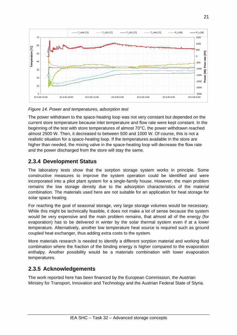
Figure 14. Power and temperatures, adsorption test
The power withdrawn to the space-heating loop was not very constant but depended on the current store temperature because inlet temperature and flow rate were kept constant. In the beginning of the test with store temperatures of almost 70°C, the power withdrawn reached almost 2500 W. Then, it decreased to between 500 and 1000 W. Of course, this is not a realistic situation for a space-heating loop. If the temperatures available in the store are higher than needed, the mixing valve in the space-heating loop will decrease the flow rate and the power discharged from the store will stay the same.
2.3.4 Development Status The laboratory tests show that the sorption storage system works in principle. Some constructive measures to improve the system operation could be identified and were incorporated into a pilot plant system for a single-family house. However, the main problem remains the low storage density due to the adsorption characteristics of the material combination. The materials used here are not suitable for an application for heat storage for solar space heating.
For reaching the goal of seasonal storage, very large storage volumes would be necessary. While this might be technically feasible, it does not make a lot of sense because the system would be very expensive and the main problem remains, that almost all of the energy (for evaporation) has to be delivered in winter by the solar thermal system even if at a lower temperature. Alternatively, another low temperature heat source is required such as ground coupled heat exchanger, thus adding extra costs to the system.
More materials research is needed to identify a different sorption material and working fluid combination where the fraction of the binding energy is higher compared to the evaporation enthalpy. Another possibility would be a materials combination with lower evaporation temperatures.
2.3.5 Acknowledgements The work reported here has been financed by the European Commission, the Austrian Ministry for Transport, Innovation and Technology and the Austrian Federal State of Styria.
IEA SHC – Task 32 – Advanced storage concepts

22
2.3.6 References 1. Welteroth, J., Mittelbach, W.: High Energy Density Sorption Heat Storage for Solar
Space Heating (HYDES HEAT STORAGE), final report of EU project in the JOULE III program, contract number JOR3-CT98-0199.
2. Wagner, Waldemar; Jähnig, Dagmar; Hausner, Robert; Isaksson, Charlotta: final reports EU project MODESTORE (Modular High Energy Density Sorption Storage), 5th framework program DG TREN, contract number: NNE5/2001/979, final reports, Deliverable D6: System prototype storage module (Austria), Deliverable D9: Installed system equipped with monitoring devices in Austria, Deliverable D14: Final Report on Austrian Field Test Period (Performance and Evaluation).
3. Wagner, Waldemar; Jähnig, Dagmar; Hausner, Robert; Isaksson, Charlotta: Modularer Energiespeicher nach dem Sorptionsprinzip mit hoher Energiedichte (MODESTORE), final report of a project in the framework of the Austrian program ‘Haus der Zukunft’, contract number: 805768/7024 KA/TU, 2006.
4. Hadorn, J.-C., ed. Thermal Energy Storage for Solar and Low Energy Buildings .- State of the Art. 2005, Lleida University: Lleida, Spain. ISBN: 84-8409-877-X.
IEA SHC – Task 32 – Advanced storage concepts

23
2.4 NaOH Storage Robert Weber, Empa, Dübendorf, Switzerland
2.4.1 Background The NaOH storage reported here is intended as long-term heat storage with a high specific heat density [1]. The use for cooling purposes should be possible, but this is not investigated in this study. A laboratory prototype has been built (Figure 16) to show the characteristic of the process and the performance of the built in heat exchangers. The concentration ratios of the lye at different temperatures and the corresponding vapour pressure are crucial for the reachable heat power and heat capacity. With that prototype, also those operating parameters shall be optimised.
2.4.2 Design and Operating Principles The storage is working like a heat pump with a chemical (or thermal) drive. The driving force is the difference of the vapour pressures above lye and water. The vapour pressure depends on the concentration and temperature of water and lye. To charge the storage, the solar heat boils the NaOH- lye and the concentration increases. The emerging vapour is condensed at the cooled water side (Figure 15, top left). To discharge the storage, vapour is absorbed by the concentrated NaOH. The absorption process is heating the NaOH (Figure 15, top right). The prototype is designed for continuous operation with one stage (Figure 15, bottom left). Only small amounts of water and lye are pumped to the heat exchangers where charging and discharging occurs. To reach higher heat density in future storages, double stage operation is foreseen (Figure 15, bottom right). This enables hot water to be prepared at a reasonable temperature even with low concentration of the lye [2]. An advantage of the proposed system is that tanks and heat exchangers are separated.
H20 NaOH
(20°C) (150°C)
H2O vapour(45 mbar)
Charge
heat fromcollector
waste heat
ground heatexchanger
solarcollector
H20 NaOH
H2O vapour(10 mbar)
(10°C) (40°C)
Discharge
ambientheat
useful heat
ground heatexchanger heating,
hot water
Charge
Vapor
ground heatexchanger
Water
conc.Soda lye
dilutedSoda lye
Single-stageHeat exchanger
Solarcollector
Vapor
Domestichot water
Double-stageHeat exchanger
Dischargeground heatexchanger
Water
conc.Soda lye
dilutedSoda lye
Figure 15. Top: Basic concept of the NaOH store. Bottom: schematic with stores and single stage reactor (left) and two-stage reactor (right).
IEA SHC – Task 32 – Advanced storage concepts

24
Figure 16. Picture of the NaOH store.
2.4.3 Laboratory Test Results First tests with the laboratory prototype have been performed with the following results:
• The charging process of the storage is going on faster and with higher efficiency than previous calculation assumed. As a consequence, the desorption temperature doesn’t need to be 150°C, rather 120°C are sufficient.
• The discharging of the storage goes slower than expected (charging and discharging speed depends on the size and the type of heat exchanger used).
• The parasitic heat losses are higher than expected and couldn’t be neglected. Additional insulation measure have been made.
• Most of the existing Elastomers are not resistant enough to withstand the high concentrated NaOH lye.
Table 6. Design specification for NaOH storage (Calculated Values)
Parameter Calculated Performance Boundary Conditions
Storage materials weight: NaOH H2O
160 kg 160 kg
Laboratory Prototype
Storage capacity for heat 8.9 kWh Laboratory Prototype Floor space required for prototype 2 m2 Laboratory Prototype Energy density of material (NRJ4.1) (ratio to water 25/85°C)
250 kWh/m3
(3.6) Two stage prototype
Energy density of prototype (NRJ4.2) (ratio to water 25/85°C)
5 kWh/m3
(0.07) No effort has been made to optimize
the volume of the Laboratory Prototype
Charge rate 1 kW Laboratory Prototype Discharge rate 1 kW Laboratory Prototype Estimated size for 70 kWh (ratio to water 25/85°C)
1.3 m3
(0.75) Two stage storage
Estimated size for 1000 kWh (ratio to water 25/85°C)1
5 m3
(2.9) Two stage storage
Cost of material 250 €/m3 1 Assumptions: About 1m³ is needed for heat exchangers, pumps, valves and empty vessels.
IEA SHC – Task 32 – Advanced storage concepts

25
Temperature boundary conditions: Laboratory prototype Hot side Cold side Charging (Desorption of vapor) 95°C 20°C Discharging (Adsorption of vapor) 70°C 10°C Two stage prototype Charging (Desorption of vapor) 150°C 20°C Discharging (Adsorption of vapor) 70°C 10°C In water storages, heat is stored directly by filling the tank with hot water. A sorption storage stores heat indirectly. In fact, only the driving force of the heat pump is stored. Therefore, the heat capacity of sorption storages depends also on the ambient boundary conditions. The actually laboratory prototype is built to show the principle, to measure temperatures and pressures and to show the function. It isn’t build for optimizing the volume and the heat capacity.
2.4.4 Development Status The NaOH storage is a one stage laboratory prototype. It is used for gaining experience during operation and for measurements of different variables to simulate a whole double stage system with solar collectors and a borehole heat exchanger. The ongoing project will end in 2009 and shall lead to a double stage prototype. The project is supported by the Swiss Federal Office of Energy and Empa.
2.4.5 References 1. Hadorn, J.-C., ed. Thermal Energy Storage for Solar and Low Energy Buildings .- State
of the Art. 2005, Lleida University: Lleida, Spain. ISBN: 84-8409-877-X.
2. Weber, R., Dorer, V.: Long-term heat storage with NaOH, Vacuum, 2008, doi:10.1016/j.vacuum.2007.10.018.
IEA SHC – Task 32 – Advanced storage concepts

26
2.5 Characterization of magnesium sulphate as thermo chemical material for seasonal heat storage
V.M. van Essen, W.G.J. van Helden, R. Schuitema and H.A. Zondag, Energy research Centre of the Netherlands (ECN) Z.He and C.C.M. Rindt, Eindhoven University of Technology (TU/e)
2.5.1 Background A previous study at ECN [1] indicated magnesium sulphate heptahydrate (MgSO4.7H2O) as a potentially interesting thermo chemical storage material using the following reversible reaction: MgSO4.7H2O(s) + heat ⇔ MgSO4(s) + 7H2O(g) The theoretical storage density of MgSO4.7H2O is 780 kWh/m3 at temperature level of 122°C, which offers a more compact way of storing energy for the same volume in comparison to water (69 kWh/m3 at temperature range of 25-85°C). In addition to the high storage density, MgSO4.7H2O is cheap, non-toxic and non-corrosive. For these reasons, MgSO4.7H2O is studied at ECN as possible thermo chemical material for solar thermal (seasonal) heat storage.
2.5.2 Design and Operating principle
Summer
Winter
Figure 17. Operating principle of solar thermal heat storage using thermo chemical materials.
In the summer the amount of available solar energy exceeds the heating demand in the built environment. The surplus of solar energy in summer can be used to dehydrate MgSO4.7H2O, as shown in Figure 17. In the winter the available solar energy is not enough to meet the heating demand. However, when the separately stored MgSO4 and H2O are mixed, the stored solar energy is released and can be used to meet the heating demand in winter
IEA SHC – Task 32 – Advanced storage concepts

27
2.5.3 Laboratory test results Available literature on MgSO4.7H2O dehydration shows a disagreement on which intermediates are formed during dehydration. For example, the NBS database [3] indicates stable intermediates where 6, 4, 2 and 1 water molecules are attached to MgSO4, whereas Ruiz et al [2] suggest that dehydration proceeds via crystalline MgSO4.6H2O, which dehydrates to an amorphous intermediate state until crystalline amorphous MgSO4 is formed. To clarify the matter, it was decided to study the dehydration and hydration using the following techniques: Thermo gravimetric analysis (TGA) – changes in mass are measured as function of time when a sample is subjected to a predefined heating program.
Differential scanning calorimetry (DSC) – similar to TGA, but supplied heat instead of mass is measured as function of time.
X-ray diffraction (XRD) – non-invasive optical technique which provides information on crystal structure, chemical composition and physical properties of the material.
Scanning electron microscope (SEM) – a method of producing high resolution images of surfaces. The advantage of SEM over a normal microscope is its greater magnification (up to 100.000 times). Dehydration of MgSO4.7H2O A typical TGA and DSC curves for dehydration of MgSO4.7H2O are shown in Figure 18.
Dehydration of MgSO4.7H2O (1 K/min, dry N2 atmosphere, 10 mg)
50
55
60
65
70
75
80
85
90
95
100
25 50 75 100 125 150 175 200 225 250 275 300Temperature (C)
Mas
s (%
)
-0.9
-0.8
-0.7
-0.6
-0.5
-0.4
-0.3
-0.2
-0.1
0
0.1
Hea
t (m
W/m
g)
MgSO4.7H2O → MgSO4.6H2O + H2O
MgSO4.6H2O → MgSO4.0,2H2O + 5,8H2O
MgSO4.0,2H2O → MgSO4 + 0,2H2O
Figure 18. Experimental TGA and DSC curves for dehydration of MgSO4.7H2O. Blue line indicates TGA curve, red line indicates DSC curve.
Figure 18 shows that a change in DSC signal is accompanied with a change in mass, which indicates that a reaction takes place.
IEA SHC – Task 32 – Advanced storage concepts

28
From TGA results it can be derived that dehydration of MgSO4.7H2O occurs in three steps: first, MgSO4.6H2O is formed, followed by a gradual removal of 5.8 water molecules leading to MgSO4.0,2H2O and in the final step MgSO4 is formed. The shape of the TGA curves suggests that the first and third steps are single step reactions. The gradual removal of water molecules in the second step indicates that a sequence of dehydration reactions occurs. Unfortunately, it was not possible to identify intermediates within this second dehydration step, but it can be seen from Figure 18 that almost all dehydration occurs at a temperature below 150°C.
The first two dehydration steps are endothermic processes (indicated by the negative DSC signal) and can be used to store energy. In this regard, the second dehydration step is most interesting and corresponds to a storage density of ~417 kWh/m3. Although still 6 times larger than the storage density of water, there is a considerable difference between the experimental and theoretical storage densities, which illustrates the need for investigating the (de)hydration behaviour of salt hydrates.
The DSC curve indicates that the third dehydration step is an exothermic process, which seems odd since the removal of water appears to be endothermic (see also the first and second dehydration steps). Ruiz et al [4] suggests that the final transition includes an exothermic reaction due to recrystallization of an amorphous precursor. This suggestion was further investigated by performing an XRD experiment where a sample of MgSO4.7H2O was heated from 25 °C to 300°C at 1°C/min in gas mixture of nitrogen saturated with water vapor. Figure 19 shows experimental XRD patterns for dehydration of MgSO4.7H2O:
Figure 19. Experimental XRD pattern for dehydration of MgSO4.7H2O (see text for details).
By comparing experimental XRD patterns (peaks) with theoretical patterns, it is possible to identify some of the intermediates in the dehydration process. The first step in the dehydration of MgSO4.7H2O (see Figure 18) is also observed in the XRD pattern. In the
IEA SHC – Task 32 – Advanced storage concepts

29
temperature range of 80°C to 276 °C there are no peaks visible in the XRD patterns, which indicates the formation of an amorphous state when MgSO4.6H2O is dehydrated. This means that the second dehydration step also includes the endothermic transition from a crystalline state (MgSO4.6H2O) to an (unidentified) amorphous state.
At final temperature of 300°C crystalline MgSO4 is formed, which confirms the suggestion by Ruiz et al [4] that the third step in dehydration process includes a change in structure, and that dehydration is completed at 300°C. Melting Melting of the material should be avoided since it reduces the bed porosity of the material, and thereby the vapour transport through the bed, limiting the ability of the material to take up water again. Initial tests showed that the surface of magnesium sulphate grains were (visually) subjected to melting [5] as shown in Figure 20.
Figure 20. Scanning electron microscope (SEM) pictures of fresh, thermally dehydrated and molten magnesium sulphate.
Melting can also be observed by combining TGA and DSC signal, since melting will cause an uptake of heat without an accompanying change in mass. This effect is illustrated in Figure 21, where differential mass (dTGA/dt) and heat (DSC) are plotted as function of temperature:
IEA SHC – Task 32 – Advanced storage concepts

30
Dehydration of MgSO4.7H2O
(10 mg, 1K/min, N2+H2O atmosphere, pH2O=1.3 kPa)
-1.2
-1
-0.8
-0.6
-0.4
-0.2
0
20 30 40 50 60 70Temperature (C)
Diff
. Mas
s (a
.u.)
-1.2
-1
-0.8
-0.6
-0.4
-0.2
0
Hea
t (a.
u.)
DTA 200-500 micronDSC 20-38 micronDTA 20-38 micronDSC 200-500 micron
Figure 21. Differential mass and heat as function of temperature for 200-500 and 20-38 µm particles. The red circle indicates the peak associated with melting.
Experiments reveal that melting occurs in the temperature range of 48°C – 52 °C, thus during the first dehydration step. If dehydration is slow compared to the heating rate, MgSO4.7H2O may still be present at this temperature range and will start to melt incongruently [6]. Further investigation showed that melting can be avoided when low heating rates (<1 °C/min), small particles (<200µm) and/or small sample sizes (<5 mg) are used. In these cases, dehydration proceeds fast enough compared to the heating rate and MgSO4.7H2O will not be present at 48-52°C (see also Figure 21). Chemical kinetics of dehydration As mentioned before, the dehydration of MgSO4.7H2O proceeds through three steps involving several reactions. The complexity of the reactions can be best investigated using software packages for determination of kinetic parameters of the reactions, which was not available at the time. However, a first estimation of the kinetic parameters can be made from the TGA curves following the description by van de Voort [4]. This method is based on the fact that the maximum yield of the products from a conversion reaction occurs at the peak of the differential mass signal. At higher heating rates, the peak of the differential mass signal (Tmax) shifts to higher temperatures as illustrated in Figure 22:
IEA SHC – Task 32 – Advanced storage concepts

31
Figure 22. Experimentally determined differential mass signal as function of temperature for three different heating rates.
This shift can be used to calculate the Arrhenius parameters: pre-exponential factor (A) and activation energy (Ea). For example, let us consider the second dehydration step. From the shift in Tmax, an activation energy of 55 kJ/mol and a pre-exponential factor of 1.8x10⁵ s-1 were determined. These values were compared to Arrhenius parameters determined by Ruiz et al [4] for dehydration of MgSO4.7H2O (Ea = 55 kJ/mole and A = 1.67x10⁵ s-1) and were found to be in good agreement with each other. Hydration of MgSO4
The dehydration experiments showed that MgSO4 was formed when MgSO4.7H2O was heated up to 300°C. At room temperature (25°C) MgSO4 was exposed to a gas mixture of water and nitrogen (PH2O = 1.3 kPa, RH=40%). Figure 23 shows the experimental TGA curves for hydration using different particles sizes:
IEA SHC – Task 32 – Advanced storage concepts

32
Figure 23. Experimental TGA curves for influence of particle size on hydration of MgSO4.
The results show that MgSO4 takes up water until 91-94% of the initial mass is reached, corresponding to MgSO4.6H2O. The DSC results (not shown) indicate that heat (~200-400 kWh/m3) is released during the hydration, but so far we were unable to accurately determine the amount of released heat. The results in Figure 23 indicate that the hydration is independent on the particle size, which suggests that diffusion inside the particle is not a limiting factor. The influence of diffusion between the particles was studies by varying the mass, while keeping the particle size (in this case 38-106 µm) constant. The experiments were performed using crucibles with volume of ~72 mm3. Since the dimensions of these crucibles are known, we can study the influence of the layer thickness by varying the mass. Figure 24 shows the experimental TGA curve for hydration using sample masses.
IEA SHC – Task 32 – Advanced storage concepts

33
Figure 24. Experimental TGA curves for influence of layer thickness on hydration of MgSO4.The influence of layer thickness was studied for a 38-106 µm particle size.
Figure 24 shows that the layer thickness is an important factor for the hydration speed: thicker layers result in slower uptake of water. The results in Figures 23 and 24 indicate that the influence of particle size is limited, but that layer thickness is a very important factor for dehydration: thicker layers result in slower uptake of water, which suggests that vapour transport between particles is a limiting factor in hydration of MgSO4.
IEA SHC – Task 32 – Advanced storage concepts

34
Cyclability An important requirement for the use of magnesium sulphate for seasonal storage is that the reversible reaction can be used a number of times (=cyclability). A thick layer of material (0.8 cm corresponding to 17 grams) was subjected to repeated dehydration and hydration cycles. The samples were placed in an oven and heated up with an heating rate of 1°C/min to 150°C, which is assumed to be the maximum temperature a solar thermal collector can provide. After an isothermal period of 15 minutes at 150°C, the samples were cooled down to 20°C and placed outside the oven, allowing hydration in laboratory air (T=20°C, PH2O = 1.6 kPa (RH=70%)) for 20 hours. This procedure was repeated for two cycles, both for ambient hydration temperature of 20°C and for 40°C. The relative humidity and the temperature in the laboratory were monitored using an Escort Junior EJ-HS-B-8 data logger. Figure 25 shows the results from these experiments.
0
20
40
60
80
100
120
0 10 20 30 40 50Time (hr)
Mas
s (%
)
0
20
40
60
80
100
120
140
160
Tem
pera
ture
(C)
T = 20 CT = 40CTemperature
Figure 25. Experimental results of 2 hydration/dehydration cycles at hydration temperatures of 20°C and 40°C.
An initial mass loss of 35-40% is observed when the material is heated to 150°C, corresponding to a loss of 5 - 5.5 water molecules. For hydration at 20°C, the material takes up water until 78% of the initial mass is reached, which is considerably less than TGA hydration curves indicate. This difference can be explained by the fact that layer thickness during cyclability test was much larger (0.8 cm compared to 0.1-1 mm for TGA/DSC results). The results for hydration at 20°C indicate that magnesium sulphate can be used several times.
Figure 25 also shows the results of cyclability experiments performed at a hydration temperature of 40°C, where the dehydrated sample was placed inside an oven at 40 °C for hydration. Here too, the Escort Junior EJ-HS-B-8 data logger was used to monitor both temperature and relative humidity during hydration. The results for hydration at 40°C show no water uptake after dehydration. This can be explained by the fact that the water vapour pressure during these experiments is considerably lower than for the cyclability experiments performed at 20°C (0.4 kPa (RH=6%) at 40°C compared to 1.6 kPa (RH=70%) at 20°C), indicating the influence of water vapour pressure on hydration reaction.
Further investigation on the influence of water vapor pressure on hydration, both at 20°C and higher temperatures, will give more information on cyclability of magnesium sulphate at higher temperatures.
IEA SHC – Task 32 – Advanced storage concepts

35
Conclusions Dehydration of MgSO4.7H2O proceeds through 3 steps: MgSO4.7H2O(s) ⎯→⎯
∆MgSO4.6H2O(s) + H2O(g)
MgSO4.6H2O(s) ⎯→⎯∆
MgSO4.0,2H2O(s) + 5,8H2O(g)
MgSO4.0,2H2O(s) ⎯→⎯∆
MgSO4(s) + 0,2H2O(g)
TGA curves suggest that the first and third steps are single step reactions, while the second dehydration step consists of multiple reactions. From DSC curves it can be seen that the first 2 dehydration steps are endothermic processes and the last dehydration step is an exothermic process. The second dehydration step includes an endothermic transition from crystalline MgSO4.6H2O to an amorphous state. In the final dehydration step, an amorphous precursor converts to crystalline MgSO4, which results in an energy release and explains the observed exothermic peak in the DSC signal.
Melting of MgSO4.7H2O is observed and can be avoided when low heating rates (<1 °C/min), small particles (<200µm) and/or small sample sizes (<5 mg) are used. A first estimation of the kinetic parameters for dehydration shows a good correspondence with values found in literature.
Hydration experiments reveal that after dehydration, MgSO4 takes up water until MgSO4.6H2O is formed. The speed of hydration is influenced by the layer thickness: thicker layers result in slower water uptake. However, the effect of particle size on the hydration speed is limited, which indicates that the vapour transport between the particles is the limiting factor in hydration of magnesium sulphate.
The material shows good cyclability at 20°C, but no uptake of water is observed at 40°C. A lower water vapour pressure may be the reason for this observation, but more experiments are needed to verify this.
2.5.4 Development Status The initial characterization experiments indicate that MgSO4.7H2O can be dehydrated at temperatures below 150°C, which can be reached using solar thermal collectors. The material can take up water at 25°C, while releasing a certain amount of heat. However, the exact amount of heat released during the hydration, the influence of water vapour pressure, and the influence of temperature on the hydration of MgSO4 are unknown. These issues are currently investigated and the results will allow us to judge the full potential of MgSO4.7H2O as a thermochemical material. Recently, a software package was acquired for the determination of the kinetic parameters from TGA and DSC experiments. This package will be used to analyze hydration and dehydration processes. Based on these studies a laboratory prototype will be build and tested. The characterization procedure of MgSO4.7H2O can also be used to characterize other salt hydrates, which could perform better than MgSO4.7H2O. Future material research will focus on salt hydrates other than MgSO4.7H2O in order to find the best thermochemical material.
IEA SHC – Task 32 – Advanced storage concepts

36
2.5.5 Acknowledgements The work reported here has been financed by the Dutch Ministry of Economic Affairs by means of the EOS support scheme. The work on thermo chemical heat storage is part of the long-term work at ECN and TU/e on compact storage technologies.
2.5.6 Literature 1. Visscher, K. et al. (2004) ECN Report ECN-C—04-074:Compacte chemische
seizoenopslag van zonnewarmte; Eindrapportage, ECN, Petten
2. WAELS III: Woningen Als Energieleverend Systeem, https://www.waels.nl
3. Wagman, D.D., W.H. Evans et al., “The NBS tables of chemical thermodynamic properties: selected values for inorganic and C1 and C2 organic substances in SI units”, J. Phys. Chem. Ref. Data, 11,306 (1982).
4. Ruiz-Agudo, E., Martin-Ramos, J.D. and Rodriguez-Navarro, C., “Mechanism and kinetics of dehydration of epsomite crystals formed in the presence of organic additives”, J.Phys.Chem.B., 111, 41-52 (2007).
5. van de Voort, I.M., “Characterization of a thermochemical storage material”, Eindhoven University of Technology Master Thesis, 2007
6. Emons, H.H, Ziegenbalg, G., Naumann, R. and Paulik, F.,“Thermal decomposition of the magnesium sulphate hydrates under quasi-isothermal and quasi-isobaric conditions”, J. Therm. Anal., 36, 1265-1279 (1990)
IEA SHC – Task 32 – Advanced storage concepts

37
2.6 Open Adsorption System with Zeolite Henner Kerskes and Karola Sommer, ITW, University of Stuttgart
2.6.1 Background A new process for solar thermal space heating based on a long-term sorption store integrated in a mechanical ventilation system was developed at the Institute of Thermodynamics and Thermal Engineering, University of Stuttgart. The heat storage is based on an open process in which the heat release occurs during the adsorption of water vapour on the storage material, extruded zeolite honeycomb structures. The regeneration of the store is performed with solar thermal energy.
Initial laboratory experiments and simulation studies have shown a high performance of this process. A small-scale demonstration system built at ITW is being investigated under conditions close to practical application.
2.6.2 Design and Operating principle Starting from a conventional combi-system (a combi-store of 1000 l with 20 m² of evacuated tube collectors), a sorption store with a volume of 7,85 m³ is added to the system (see Figure 26). The necessitated humidity is provided for free thanks to the humid room outlet air. The existing controlled ventilation of the building brings about the idea of interposing an adsorption-bed between the humid outlet air and the heat recovery unit.
Figure 26. Schematic sketch of a solar equipped residential building without sorption store (left) and with sorption store (right)
Heat is released when the air flows through the sorption store, which leads to a rise in temperature so that the following heat exchanger receives much warmer, dry air. The heat of the outflowing air is transferred to the incoming fresh and cold air, whose temperature is raised by approx. 20 K. This warm air is then used for heating purposes.
A major improvement was made by using zeolite honeycomb structures called “monoliths” instead of the ordinarily employed fills. These regularly shaped bodies have a large number of small, straight channels (see Figure 27), their main advantages being a low pressure loss and better adsorption properties than fills [1].
IEA SHC – Task 32 – Advanced storage concepts

38
Figure 27. Monolith.
The additional expenditure for apparatus is little: the store, a water/air heat exchanger and a few valves. Another advantage of the concept Monosorp is the simple and flexible store design: since the store is built with the block-shaped monoliths, it can be designed in virtually any shape depending on the local space conditions. Regenerating the store with the solar system After loading the store with humidity during winter, desorption takes place in summer, using the “extra heat” delivered by the combi system when the only heat load is the domestic hot water preparation. A conventional combi system would enter stagnation after reaching the maximum store temperature and would not deliver any more heat. In the presented system, the solar energy is now used to regenerate the sorption store. The charging of the combi system is switched off when the temperature of its stand-by part has reached 80°C and is only switched on when the temperature has decreased to 70°C. In the meantime the collector loop is made available for regenerating the sorption store. When the collector temperature has reached 125°C, the solar loop is directed to an additional water/air heat exchanger. The air side of this heat exchanger receives pre-heated ambient air with a variable flow rate (max. 400 m3/h). The hot exit air is used for the regeneration of the sorption store. A controller adjusts the air flow rate to the set temperature of 160°C.
2.6.3 Laboratory test results A small-scale demonstration plant has been set up at ITW with the objective of running the presented concept under real conditions and with commercially available parts. Only the store (see Figure 28) had to be specially designed in order to ensure a uniform distribution of the air flow over the zeolitic honeycomb structures. The monoliths were manufactured at the Institute for Polymer Technology, University of Stuttgart.
Figure 27. View in the open MonoSorp store. Left picture: assembly of the monoliths; right picture: completely filled store with thermocouples for temperature measurements in the store).
Adsorption
IEA SHC – Task 32 – Advanced storage concepts

39
Because of a delay in the manufacturing process of the zeolite honeycomb structures, first adsorption experiments were performed on a fill of spheres with diameters from 1.6 to 2.5 mm. Preceding the adsorption shown in Figures 29 and 30, the zeolites were dried in an oven at 180°C.
HepotTa
Figure 29. Adsorption in the tested store with fill of spheres: progression of the temperature front in the store in axial direction.
Figure 30. Adsorption in the tested store with fill of spheres: progression of the absolute humidity of inlet and outlet air (xin, xout) and cumulated mass of adsorbed water (mads). Air inlet conditions: temperature 19°C, relative humidity 40%, flow rate 12 m³/h.
umid room air flowed through the store until the zeolite was saturated. Figure 29 shows the volution of the temperature distribution in the store with time. The temperature sensors were laced at 5 positions in the flow axis of the store (see drawing on right side of Figure 29). and f the store inlet and outlet. Figure 30 shows the humidity of the store inlet and outlet air and
he cumulated mass of adsorbed water. he steep temperature profiles in the store and the humidity profile of the store outlet point to steep adsorption front (i.e. good adsorption kinetics). This behaviour leads to a more or
IEA SHC – Task 32 – Advanced storage concepts

40
less constant store outlet temperature during the whole adsorption phase. The break-through of the adsorbate occurs only when the store is nearly completely saturated. This adsorption behaviour is desired in order to get a sufficient temperature lift between air inlet and outlet. The maximum temperature lift in the store was approx. 22 K.
Desorption
An important issue is the solar thermal generation of hot air for the desorption process. For a successful solar thermal desorption (i.e. the adsorbens has to reach temperatures of 170°C), two conditions have to be fulfilled. Firstly, the employed commercial solar collectors have to have a sufficient thermal efficiency for this purpose, especially at high temperatures. Secondly, the system set-up has to be adequate for the necessary temperature lift of the air from room conditions to 170°C.
Experiments were performed that proved the good functioning of the demonstration plant. Measurements showed that at a mean collector temperature of 180°C, the collector efficiency reaches approx. 40%. The system set-up allowed store temperatures of 170°C (conditions: air flow rate: 50 m³/h, water flow rate: 80 l/h, water temperature at heat exchanger inlet: 180°C).
Experiments with transient heat power input pointed out the importance of the store’s insulation, an appropriate heat management and control strategies. Table 7 shows results of experiments and calculations performed on a store filled with monoliths. The measured energy density of extruded zeolite structures is approx. 130 kWh/m³ if one considers only adsorption enthalpy. Additionally, because of the high regeneration temperatures, sensible heat of up to 180°C is stored in the adsorbent. This increases the energy density to approx. 160 kWh/m³. When considering a system simulation of one year, weather conditions allowing a partial regeneration of the store occur more and more frequently from April on. This increases again the amount of stored sensible heat and adsorption enthalpy to approx. 180 kWh/m³. This latter value resulting from a system simulation is not used in table 7.
IEA SHC – Task 32 – Advanced storage concepts

41
Table 7. Test results of the MonoSorp store filled with extruded honeycomb structures made of zeolite 4A.
Parameter Measured Performance Boundary Conditions Storage materials weight:
zeolite (dry) 70 kg extruded zeolite honeycomb structures
steel 10 kg storage capacity for heat 12 kWh Floor space requirements for prototype 0.4 m² Energy density of the material (NRJ4.1) 160 kWh/m³ (ratio to water 25/85) (2.3)
adsorption enthalpy + sensible heat
Energy density of prototype store (NRJ4.2) 120 kWh/m³ adsorption enthalpy only (ratio to water 25/85) (1.7) Charge rate 2 … 2.5 kW
Discharge rate 1 … 1.5 kW 10/35°C, air flow rate approx. 150 m³/h
Estimated size for 70 kWh 0.54 m³ (ratio to water 25/85) (1.9)
Assumes a slightly lower ratio of sorption material volume to additional system volume
Estimated size for 1000 kWh 7.7 m³ (ratio to water 25/85) (1.9)
Assumes a slightly lower ratio of sorption material volume to additional system volume
Cost for material 2500 - 3500 €/m³
Zeolite 4A Costs for extrusion in big amount unknown
2.6.4 Development status It was shown that the demonstration plant could be built with commercially available parts with the exception of the sorption store. The performed adsorption and desorption cycles proved the functioning of the concept and of the system set-up: The humidity of the room outlet air is sufficient for the necessary temperature lift for room heating. The expected thermal performance (energy density) of the system was reached. The complete regeneration of the store can be achieved as well under stationary as under dynamic conditions resulting from the varying solar energy input.
Further research has to be done for the development of control strategies that allow an efficient solar heat management. In a next step, a prototype should be integrated into the heating system of a one-family house.
IEA SHC – Task 32 – Advanced storage concepts

42
2.6.5 Acknowledgements The work reported here has been financed by BWPlus, a program of Land Baden-Württemberg, Germany.
2.6.6 Literature 1. J.Hammer; H.G. Fritz: Extrusion of zeolitic honeycomb structures using thermoplastic
polymers as plasticising aid and binder, 2002, Institut für Kunststofftechnologie der Universität Stuttgart
2. H. Kerskes und H. Müller-Steinhagen. MonoSorp - Ein weiterer Schritt auf dem Weg zur vollständigen solarthermischen Gebäudeheizung. Tagungsband zum 14. Symposium Thermische Solarenergie, S. 169 – 173, 2004. Otti-Technologie-Kolleg, Regensburg, ISBN 3-934681-33-6.
IEA SHC – Task 32 – Advanced storage concepts

43
3 COMPARISON OF PROTOTYPES Table 8 shows a comparison of the key figures for the thermochemical and sorption technologies studied in IEA-SHC Task 32. The different technologies are at very different stages of development. Four of the tested prototypes are closed systems and act as thermally driven heat pumps, whereas the fifth is an open adsoption system. The sixth technology reported here is also planned to be a closed system, but as yet only material properties have been investigated. The TCA technology is in the process of commercialisation by the Swedish company ClimateWell AB, and over 35 storage systems have been installed, mostly in Spain. However, the storage system is sold as a chemical heat pump with the main emphasis on cooling, the storage for cold being more important than for heat. The complete systems usually have solar collectors with gas backup, and are designed for both heating and cooling. The storage density for cold, when compared to water, is also more favourable, with a factor 4.7 for the commercial machines as opposed to only 1.2 for heat storage. This is due to the fact that the temperature range available for water storage for cold is much smaller (~10°C) than for heat (~60°C). The other technologies are at best in the prototype stage with no companies intending to develop and market them. The Modestore store was developed in a European project, and the main company within the project (Sortech) is commercialising the technology as a heat pump with essentially no heat storage. The other four technologies are at the lab prototype stage.
For short term heat storage (70 kWh store), the highest energy density is achieved by dehydration/hydration of MgSO4.7H2O and for the open adsorption process Monosorp. For these the energy density is twice or more than that for water, while the three-phase process with LiCl has only 60% higher energy density. The other processes are no better or worse than water in this respect. The main reason for the relatively low energy densities is that all the closed processes need reactors and condenser/evaporators that add extra space to the store unit. In addition, all of the storage systems lose heat during the charge and discharge process due to irreversibilities in the processes themselves. Most of this is due to the different temperature levels of charge/discharge and the related sensible energy between these.
However, for larger stores (1000 kWh) the energy density is generally higher due to the fact that the reactors and condenser/evaporators are relatively small in comparison to the store. For dehydration of MgSO4.7H2O, TCA and NaOH the storage systems have between 2.5 and 2.9 times the energy density of water, whereas that for the Monosorp technology is nearly two times that of water. An additional advantage compared to water, is that with all these technologies the energy can be stored indefinitely. Note that the calculations made here are not for long term storage as such, as the sensible heat losses are not considered. Heat losses from the stores, are in general lower than those for water principally due to smaller volumes, and the fact that for several of the technologies only the reactors are kept at the operating temperature. The repeated heating and cooling of the store for charge/discharge during one season can mean lower store efficiencies, and heat recovery will be very important. None of these aspects are taken into account here, so the figures are only indicative. The best indication of the stores performance is in a system context, and three of these stores have been simulated (see report B6).
The Monosorp concept has several advantages over the other technologies. Firstly it is an open process, thus requiring no vacuum components or source of “free” low grade heat for evaporation of water. Secondly the store is built into the ventilation system with its inherent and efficient heat recovery. It is thus a relatively simple system concept in terms of extra necessary components compared to a standard solar combisystem. The main disadvantages
IEA SHC – Task 32 – Advanced storage concepts

44
are the limited discharge rate, determined by the natural water content in the building, and the fact that the store needs to be charged with air at above 150°C – requiring relatively large ducts and thus higher heat losses.
In terms of material cost, LiCl, silical gel and zeolite are very expensive and not suited to seasonal storage for this reason. Even the less expensive materials studied here, NaOH are far more expensive than water. MgSO4.7H2O is expensive, but this is balanced by its higher energy density. As there is no commercial extrusion process for zeolite, the cost of large quantities of extruded material is only a rough estimate. However, the cost for the substance is relatively low, which is essential for seasonal storage applications. The cost for the whole storage system has not been estimated here. For the ClimateWell 10, the projected cost is ~8000€ for a heat pump system consisting of two units in parallel, with a total heat storage capacity of 70 kWh.
Of the materials studied, MgSO4.7H2O has the highest energy density, but the initial material characterisation suggests that the working energy density is only slightly half the theoretical value. The initial material characterisation also shows that material thickness is an important factor in dynamics and thus practical storage applications and that melting is also important. However, no prototype with the material has been built, and thus its use in practical applications is as yet unknown.
IEA SHC – Task 32 – Advanced storage concepts

45
Table 8. Comparison of key figures for materials and technologies for thermochemical and sorption stores studied in IEA-SHC Task 32.
Parameter TCA
80-100°C
NaOH 95°C test
150°C calculated
Modestore
88°C
SPF
180°C
Monsorp
180°C
ECN
150°C Type of technology Closed
three phase absorption
Closed two phase absorption
Closed adsorption
Closed adsorption
Open adsorption
Closed Thermo-chemical
Cost of material 3600 €/m3 250 €/m3 4300 €/m3 2-3000 €/m3 12500-3500 €/m³ 4870 €/m³ Storage materials weight:
LiCl salt 54 kg Water117 kg
Steel 47 kg
NaOH160 kg Water160 kg
Silica gel 200 kg Water 30 kg Steel 100 kg Copper 50 kg
Zeolite 13X 7 kg Zeolite 4A 70 kgSteel 10 kg
MgSO4.7H2O
Storage capacity for heat 35 kWh 8.9 kWh 13 kWh 1 kWh 12 kWh - Floor space required for prototype 0.46 m2 2 m2 0.4 m2 0.09 m2 0.4 m2 - Energy density of material (NRJ4.1) (ratio to water 25/85°C)
253 kWh/m3
(3.6) 250 kWh/m3
(3.6) 50 kWh/m3
(0.71) 180 kWh/m3
(~ 3) 160 kWh/m3
(2.3) 420 kWh/m3
(6.1) Energy density of prototype - heat (NRJ4.2) (ratio to water 25/85°C)
85 kWh/m3
(1.2) 5 kWh/m3
(0.07) 33.3 kWh/m3
(0.48) 57.8 kWh/m3
(~ 1) 120 kWh/m3
(1.7) -
Energy density of prototype - cold (ratio to water 7/17°C)
54 kWh/m3
(4.7) - - - - -
Charge rate 15 kW 1 kW 1.0 - 1.5 kW - 2.0 - 2.5 kW - Discharge rate 8 kW 1 kW 0.5 – 1.0 kW 0.8 kW / 1.8 kW 1.0 - 1.5 kW - Estimated size for 70 kWh (ratio to water 25/85°C)
0.64 m3
(1.6) 1.3 m3
(0.75) 1.7 m3
(0.59) 1.2 m3
(~ 1) 0.54 m3
(1.9)
20.4 m3
(2.5) Estimated size for 1000 kWh (ratio to water 25/85°C)
5.3 m3
(2.7) 5 m3
(2.9) 23 m3
(0.62) 17 m3
(~ 1) 7.7 m3
(1.9)
25.6m3
(2.5) 1 Cost for large quantity of extruded material is unknown and is estimated for zeolite 4A. 2 Estimations are based on experimental storage density of ~420 kWh/m3 for reaction MgSO4.6H2O + heat ↔ MgSO4.0,2H2O + 5,8H2O
IEA SHC – Task 32 – Advanced storage concepts

46
4 Conclusions For short term storage, none of the prototypes offer a much greater energy density that water (less than two times compared to water using 25 - 85°C range). The chemical storage using MgSO4.7H2O has potentially a higher energy density. The energy density can only be slightly greater than that for water, mainly due to the space required for heat exchangers and other components. In addition all of the storage systems lose heat during the charge and discharge process due to irreversibilities in the processes themselves. Most of this is due to the different temperature levels of charge/discharge and the related sensible energy between these. Four of the tested prototypes can be used as thermally driven heat pumps, although only one is designed (and tested in the field) for this application. The energy density for cold storage for this prototype is significantly higher than for water (over 5 times) mainly due to the fact that only a small temperature range can be used for the water store.
For longer term storage the energy density for the TCA (with LiCl as material) and NaOH storage systems is nearly three times that of water and that for Monosorp is two times that of water. The theoretical storage density for MgSO4.7H2O is 780 kWh/m3 but with suitable operating conditions it is reduced to 420 kWh/m3. A great advantage that chemical and sorption storage has compared to water, is that once the sensible heat from the solution has been lost (or recovered), the energy can be stored indefinitely. However, the cost of the material is very important for long term storage, and Lithium Chloride is expensive for seasonal storage as are silica gel and zeolite. MgSO4.7H2O is also relatively expensive, but due to the higher energy density it is more interesting. However, it has not yet been shown to work in a prototype. Further research into inexpensive, high energy density materials is required to go further in this field.
It is not possible at this stage to determine definitely which type of process is best suited for long term storage, but the current materials for closed adsorption are a long way from being of interest for this application. However, for the Monosorp concept, where open adsorption is used together with a standard ventilation system using heat recovery, the potential is very promising. The main limiting factor is the moisture availability in the exhaust air from the building, as this is the source for rehydration of the sorbent. Further research is required in order to determine the practical limitations.
The work reported here shows that significant advances have been made in terms of chemical and sorption storage. New concepts have been developed, not only to the laboratory prototype stage but even to successful field trials. Short term sorption storage for cooling using the thermochemical accumulator process is on the verge of full commercialisation while the Monosorp project has shown that an open adsorption process can potentially provide long term storage in relatively simple systems with current materials. Work in Holland with systematic, long term studies on materials for seasonal storage of solar heat point the way to an interesting future in the field. Further, long term research is required, especially in terms of materials, in order to realise the full potential of solar energy for heating and cooling.
IEA SHC – Task 32 – Advanced storage concepts