lag correlator testing aria meyhoefer carnegie mellon university summer 2001
Post on 20-Dec-2015
214 views
TRANSCRIPT

Lag Correlator Testing
Aria Meyhoefer
Carnegie Mellon University
Summer 2001

The Lag Correlator
• What it is
• How it works
• What I did with it
– Reflections
– Transmissions
– Signal Response
• Conclusions

17 Unit Lag Correlator
Diode Array
Inductor
Capacitor
Balun

How It Works Antennas read signals off the
sky with path difference depending on source angle
The correlator also allows measurement of the spectrum of any signal detected
Each element of mixer array in the correlator measures the power from a particular direction
Inside correlator delay lines remove signal path delays
Signals travel along paths of equal length to Correlator

Testing the Correlator
• Signal Response Test– Send same signal* into both inputs of correlator– Use different path lengths to create interference– Read response from oscilloscope
• Reflections Test– Send signal* into correlator through directional coupler– Terminate other input and output– Power reflects back though directional coupler to oscilloscope
• Transmissions Test– Send a signal* into one input of correlator– Read signal from other input of correlator– Find attenuation of correlator
* Same microwave signal of 9dBm from 0.01 to 26.5 GHz was always used
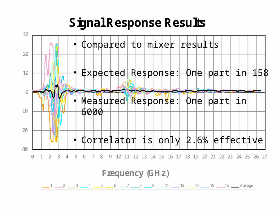
Signal Response Results
-30
-20
-10
0
10
20
30
0 1 2 3 4 5 6 7 8 9 10 11 12 13 14 15 16 17 18 19 20 21 22 23 24 25 26 27
Frequency (GHz)
Voltage (mV)
1 2 3 4 5 6 7 8 9 11 12 14 15 16 Average
• Compared to mixer results
• Expected Response: One part in 158
• Measured Response: One part in 6000
• Correlator is only 2.6% effective

Reflections Results
• Left input reflects 21% of the power• Right input reflects 16% of the power

Transmission Results
• 0.03 mV from right to left
• 0.02 mV from left to right
• Sweep generator outputting 0.4 V
• Average attenuation of about 42 dB
10LOG10
V1
V2
⎛
⎝ ⎜ ⎞
⎠ ⎟ =dB

Summary
• Correlator Response only 2.6%
• Correlator Reflects about 18.5% power
• Attenuation of 42 dB

Thanks
• Jeff Peterson – Carnegie Mellon
• Jeff Rapadas – Device Technologies