lambda 20/lambda 40 installation and maintenance guide · installation and maintenance guide . ......
TRANSCRIPT

Lambda 20/Lambda 40 Installation and
Maintenance Guide

Release History
Part Number Release Publication Date
09935055 A November 1996 B July 2000
User Assistance PerkinElmer Ltd Post Office Lane Beaconsfield Buckinghamshire HP9 1QA Printed in the United Kingdom. Notices The information contained in this document is subject to change without notice. PerkinElmer makes no warranty of any kind with regard to the material, including, but not limited to, the implied warranties of merchantability and fitness for a particular purpose. PerkinElmer shall not be liable for errors contained herein for incidental consequential damages in connection with furnishing, performance or use of this material. Copyright Information This document contains proprietary information that is protected by copyright. All rights are reserved. No part of this publication may be reproduced in any form whatsoever or translated into any language without the prior, written permission of PerkinElmer, Inc. Copyright © 2000 PerkinElmer, Inc. Trademarks Registered names, trademarks, etc. used in this document, even when not specifically marked as such, are protected by law. UV WinLab is a trademark of PerkinElmer, Inc. PerkinElmer is a registered trademark of PerkinElmer, Inc.

Contents
3
Contents Contents .......................................................................................................... 3 Safety Information........................................................................................ 5 Safety Information.......................................................................................... 7
Safety Information in the Handbook ....................................................... 7 IEC 1010 Compliance ............................................................................. 8 CSA Compliance ..................................................................................... 8 UL Compliance ....................................................................................... 8 Electrical Protection ................................................................................ 8 Electrical Safety....................................................................................... 8 Electromagnetic Compatibility (EMC) ................................................. 10 Environment .......................................................................................... 12 Symbols Used on the Instrument........................................................... 14
Preface ......................................................................................................... 17 Preface .......................................................................................................... 19
Application ............................................................................................ 19 Documentation ...................................................................................... 20
Basic Installation......................................................................................... 21 Basic Installation .......................................................................................... 23
Overview ............................................................................................... 23 Preparing the Working Area.................................................................. 23 Unpacking and Inspection ..................................................................... 25 Equipment Provided .............................................................................. 26 System Configuration............................................................................ 27 Connecting to the Electrical Supply ...................................................... 28 Single Cell Holder ................................................................................. 29 Minimum Volume Applications............................................................ 34 Setting up the Printer ............................................................................. 35
Accessory Installation................................................................................. 37 Accessory Installation................................................................................... 39
General .................................................................................................. 39 Linear Transporter ................................................................................. 43 Temperature Sensor............................................................................... 44 Multi-sippers.......................................................................................... 45 Autosampler .......................................................................................... 46 Personal Computer ................................................................................ 47
Maintenance ................................................................................................ 49

Lambda 20/40 Installation & Maintenance Guide
4
Maintenance.................................................................................................. 51 Obtaining Service .................................................................................. 51 Daily Care.............................................................................................. 51 Cleaning the Sample Compartment....................................................... 52 Use and Care of Cells ............................................................................ 54 Replacing a Lamp.................................................................................. 55 Changing Fuses ..................................................................................... 65 Maintaining the Internal Printer ............................................................ 66
Replacement Parts ...................................................................................... 69 Replacement Parts ........................................................................................ 71 System Description ..................................................................................... 73 System Description....................................................................................... 75
Features ................................................................................................. 75 Optical System Lambda 20 ................................................................... 75 Optical System Lambda 40 ................................................................... 78
Technical Data ............................................................................................ 81 Technical Data .............................................................................................. 83
Lambda 20 ............................................................................................. 83 Lambda 40 ............................................................................................. 87
Translations of Warnings........................................................................... 91 Translations of Warnings.............................................................................. 93 Index .......................................................................................................... 103 Index ........................................................................................................... 105

Safety Information 1


Safety Information
7
Safety Information
Safety Information in the Handbook
This handbook contains information and warnings that must be followed by the user to ensure safe operation and to maintain the instrument in a safe condition.
Possible hazards that could harm the user or result in damage to the instrument are clearly stated at appropriate places throughout this handbook.
The following safety conventions are used throughout this handbook:
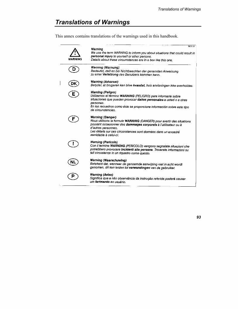
WARNING
We use the term WARNING to inform you about situations that could result in personal injury to yourself or other persons.
Details about these circumstances are in a box like this one.
CAUTION
We use the term CAUTION to inform you about situations that could result in serious damage to the instrument or other equipment
Details about these circumstances are in a box like this one.
Translations of the warning messages used in this handbook are given in Translations of Warnings on page 93.
Before using the instrument it is essential to read the manual carefully and to pay particular attention to any advice concerning potential hazards that may arise from the use of the instrument. The advice is intended to supplement, not supercede the normal safety code of behavior prevailing in the user’s country.

Lambda 20, Lambda 40 UV/Vis Spectrometers
8
IEC 1010 Compliance
This instrument has been designed and tested in accordance with IEC 1010-1: Safety requirements for electrical equipment for measurement, control, and laboratory use, and Amendment 1 to this standard.
CSA Compliance
This instrument meets the Canadian Standards Association (CSA) Standard CAN/CSA-C22.2 No. 1010.1-92: Laboratory Equipment.
UL Compliance
This instrument meets the Underwriter Laboratories (UL) Standard UL 3101-1/Oct.93: Electrical Equipment for laboratory use, part 1: general requirements.
Electrical Protection
Insulation: Class I as defined in IEC 1010-1.
Installation Category: The instruments are able to withstand transient overvoltage according to Installation Category II as defined in IEC 1010-1 and IEC 664.
Pollution Degree: The equipment will operate safely in environments that contain non-conductive foreign matter and condensation up to Pollution Degree 2 as defined in IEC 1010-1 and IEC 664.
Electrical Safety
To ensure satisfactory and safe operation of the instrument, it is essential that the green/yellow lead of the line power cord is connected to true electrical earth (ground).
If any part of the instrument is not installed by a PerkinElmer service representative, make sure that the line power plug is wired correctly:

Safety Information
9
Cord Lead Colors Terminal
International USA
Live Brown Black
Neutral Blue White
Protective Conductor (earth/ground)
Green/Yellow Green
WARNING
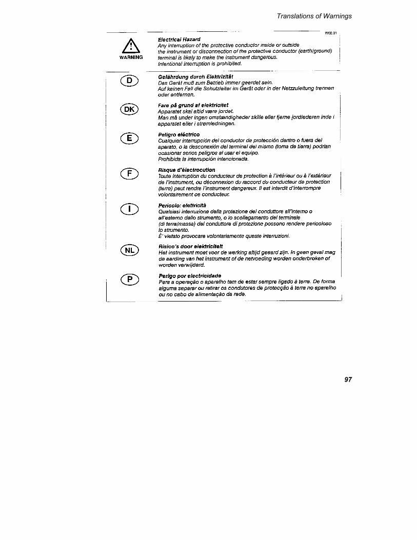
Electrical Hazard Any interruption of the protective conductor inside or outside the instrument or disconnection of the protective conductor (earth/ground) terminal is likely to make the instrument dangerous. International interruption is prohibited.
Lethal voltages are present in the instrument • Even with the power switch OFF, line power voltages can still be
present within the instrument. • When the instrument is connected to line power, terminals may be
live, and opening covers or removing parts (except those to which access can be gained without the use of a tool) is likely to expose live parts.
• Capacitors inside the instrument may still be charged even if the instrument has been disconnected from all voltage sources.
When working with the instrument:
• Connect the instrument to a correctly installed line power outlet that has a protective conductor (earth/ground).
• Do not attempt to make internal adjustments ore replacements except as directed in this handbook.
• Do not operate the instrument with any covers or parts removed.

Lambda 20, Lambda 40 UV/Vis Spectrometers
10
• Servicing should be carried out only by a PerkinElmer service representative or similarly authorized and trained person.
• Disconnect the instrument from all voltage sources before opening it for any adjustment, replacement, maintenance, or repair. If, afterwards, the opened instrument must be operated for further adjustment, maintenance, or repair, this must only be done by a skilled person who is aware of the hazard involved.
• Use only fuses with the required current rating and of the specified type for replacement. Do not use makeshift fuses or short-circuit the fuse holders.
• Whenever it is likely that the instrument is no longer electrically safe for use, make the instrument inoperative and secure it against any unauthorized or unintentional operation.
The instrument is likely to be electrically unsafe when it: • Shows visible damage; • Fails to perform the intended measurement; • Has been subjected to prolonged storage under unfavorable conditions; • Has been subjected to severe transport stresses.
Electromagnetic Compatibility (EMC)
European Union (EMC Directives)
This instrument has been designed and tested to meet the requirements of the EC Directives 89/336/EEC and 92/31/EEC. It complies with the generic EMC standards EN 50 081-1 (rf emissions) and EN 50 082-1 (immunity) for domestic, commercial, and light industrial environments.

Safety Information
11
This instrument has passed the following EMC tests:
Emission: EN 50 081-1:92 Immunity: EN 50 082-1:92
Emission of conducted and radiated noise
EN 55 011:91 EN 60 555-2:87 EN 60 555-3:87
Electromagnetic Compatibility IEC 801-2:91 IEC 801-3:84 IEC 801-4:88 IEC 801-5:90
United States (FCC)
This instrument is classified as a digital device used exclusively as industrial, commercial, or medical equipment. It is exempt from the technical standards specified in Part 15 of the FCC Rules and Regulations, based on Section 15.103[c].
Japan (FCC)
This instrument has been tested and found to comply with the limits of a Class A digital device, pursuant to Part 15 of the FCC Rules. These limits are designed to provide reasonable protection against harmful interference when the equipment is operated in a commercial environment. This equipment generates, uses, and can radiate radio frequency energy and, if not installed and used in accordance with the instruction manual, may cause harmful interference to radio communications. Operation of this equipment in a residential area is likely to cause harmful interference in which case the user will be required to correct the interference at his own expense. Changes or modifications not expressly approved by the manufacturer could void the user’s authority to operate the equipment.

Lambda 20, Lambda 40 UV/Vis Spectrometers
12
Environment
Operating Conditions
WARNING
Explosive Atmosphere
This instrument is not designed for operation in an explosive atmosphere.
The instrument will operate correctly under the following conditions:
• Indoors.
• Ambient temperature +15 ºC to +35 ºC.
• Ambient relative humidity 20% to 80%, without condensation.
• Altitude in the range 0 m to 2000 m.
Storage Conditions
You can store the instrument safely under the following conditions:
• Indoors.
• Ambient temperature +15 ºC to +35 ºC.
• Ambient relative humidity 20% to 80%, without condensation.
• Altitude in the range 0 m to 2000 m.
When you remove the instrument from storage, before putting it into operation allow it to stand for at least a day under the approved operating conditions.

Safety Information
13
Chemicals
Use, store, and dispose of chemicals that you require for your analyses in accordance with the manufacturer’s recommendations and local safety regulations.
WARNING
Hazardous Chemicals Some chemicals used with this instrument may be hazardous or may become hazardous after completion of an analysis.
The responsible body (for example, Laboratory Manager) must take the necessary precautions to ensure that the surrounding workplace and instrument operators are not exposed to hazardous levels of toxic substances (chemical or biological) as defined in the applicable Material Safety Data Sheets (MSDS) or OSHA, ACGIH, or COSHH documents.
Venting for fumes and disposal of waste must be in accordance with all national, state and local health and safety regulations and laws.
OSHA: Occupational Safety and Health Administration (U.S.A.) ACGIH: American Conference of Governmental Industrial Hygienists COSHH: Control of Substances Hazardous to Health (U.K.)
Toxic Fumes
If you are working with volatile solvents or toxic substances, you must provide an efficient laboratory ventilation system to remove vapors that may be produced when you are performing analyses.
Waste Disposal
Waste containers may contain corrosive or organic solutions and small amounts of the substances that were analyzed. If these materials are toxic, you may have to treat the collected effluent as hazardous waste. Refer to your local safety regulations for proper disposal procedures.
Lambda 20, Lambda 40 UV/Vis Spectrometers
14
Deuterium lamps and other spectral lamps are maintained under reduced pressure. When you dispose of lamps that are defective or otherwise unusable, handle them correctly to minimize the implosion risk.
UV Radiation
You should be aware of the health hazards presented by ultraviolet radiation.
• When the deuterium (UV) lamp is illuminated, do not open the spectrophotometer covers unless specifically instructed to do so in the manual.
• Always wear UV-absorbing eye protection when the deuterium lamp is exposed.
• Never gaze into the deuterium lamp.
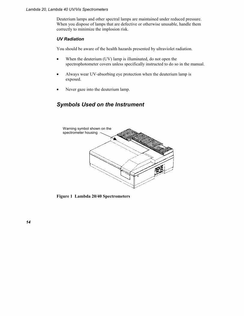
Symbols Used on the Instrument
Figure 1 Lambda 20/40 Spectrometers
Warning symbol shown on the spectrometer housing

Safety Information
15
Warning Labels on the Instrument
Figure 2 Lambda 20/40 Spectrometers
Warning labels shown on the inside of the lamp compartment

Lambda 20, Lambda 40 UV/Vis Spectrometers
16
The following warnings are shown on the inside of the lamp compartment.
DANGER HIGH
VOLTAGE
DANGER HAUTE
TENSION
WARNING UV RADIATION-HARMFUL TO THE EYES HOT COMPONENTS – RISK OF BURNS
ACHTUNG
UV-STRAHLUNG-GEFÄHRDUNG DER AUGEN HEISSE BAUTEILE –
VERBRENNUNGSGEFAHR
ATTENTION RADIATION UV-DOMMAGEABLE POUR
LES YEUX – PARTIES CHAUDES RISQUE DE BRULURES

Preface 2

Preface
19
Preface
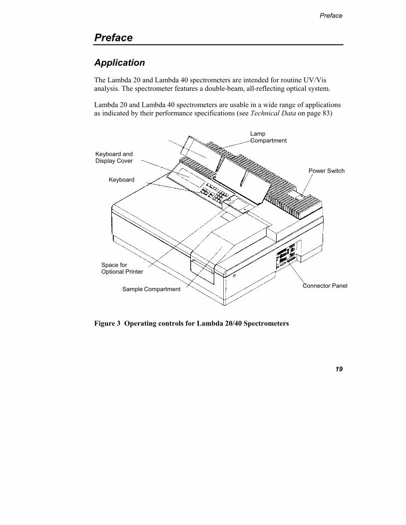
Application
The Lambda 20 and Lambda 40 spectrometers are intended for routine UV/Vis analysis. The spectrometer features a double-beam, all-reflecting optical system.
Lambda 20 and Lambda 40 spectrometers are usable in a wide range of applications as indicated by their performance specifications (see Technical Data on page 83)
Figure 3 Operating controls for Lambda 20/40 Spectrometers
Lamp Compartment
Power Switch
Connector Panel
Space for Optional Printer
Sample Compartment
Keyboard
Keyboard and Display Cover

Lambda 20, Lambda 40 UV/Vis Spectrometers
20
Documentation
A documentation package is provided with the spectrometer:
• Installation and Maintenance Guide This handbook describes the installation, setup, and maintenance procedures for the spectrometer. It also includes a detailed description of the spectrometer and a list of consumables and replacement parts.
• Operation Guide This handbook contains comprehensive information on operating the spectrometer and describes the parameters used.

Basic Installation 3


Basic Installation
23
Basic Installation
Overview
For spectrometers with installation, the initial installation will be performed by a PerkinElmer service representative. After receipt of the instrument, please contact your PerkinElmer office or representative for further information.
For spectrometers without installation, you can easily install the instrument by following the directions given in the table below.
If you intend to use accessories, for example a cell changer or sipper, refer to Accessory Installation on page 39 to install these accessories.
Preparing the Working Area
For maximum stability and minimum maintenance observe the following requirements when siting the instrument:
• A firm base free from vibration.
• Enough space around and underneath the instrument for efficient air circulation.
• A constant temperature between 15 ºC and 35 ºC.
• Constant humidity between 20% and 80% relative humidity.
• An atmosphere free from dust and corrosive fumes.
• Keep out of direct sunlight. Illumination with diffuse lighting is ideal.

Lambda 20, Lambda 40 UV/Vis Spectrometers
24
• A suitable source of electrical power should be located in the vicinity of the instrument. Electrical power must be available at a proper earth-grounded 3-wire electrical outlet. Please refer to Technical Data on page 83 for the electrical ratings of the spectrometer.
• The standard sample compartment baseplates have drain holes in them to run off spilled liquids to the benchtop underneath the instrument. You can place a sheet of thick filter paper under the instrument, if required.
Figure 4 Space Requirements
Front view
Right side view
56 cm
65 cm
26 cm

Basic Installation
25
Unpacking and Inspection
1. Unpack the components carefully. Keep the packing materials for possible future storage or reshipment.
2. Examine the components for any signs of damage in shipment. In the event of damage or missing parts, file an immediate claim with the authorized carrier, and inform your PerkinElmer office or representative.
After the instrument has been unpacked, check the exterior and interior for possible damage as follows:
1. Check the entire outer cabinet of the spectrometer for damage.
2. Make sure that terminals, fuse holders, etc. are not damaged.
3. Open the sample compartment cover, checking that it moves freely without binding. The compartment must be free of dust or other foreign matter.
4. Close the sample compartment cover.
5. Open the lamp compartment as described in Halogen Lamp Replacement on page 56.
6. Check for damages or loose cables.
7. Close the lamp compartment.
NOTE: We recommend that the initial installation of the spectrometer should be performed by a PerkinElmer service representative. After receipt of the instrument, please contact your PerkinElmer office or representative for further information.
You are required to prepare a suitable working space.
Lambda 20, Lambda 40 UV/Vis Spectrometers
26
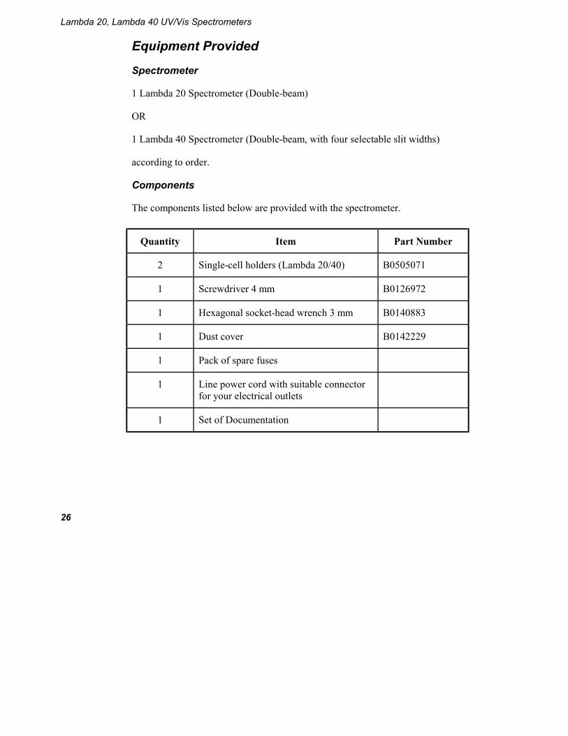
Equipment Provided
Spectrometer
1 Lambda 20 Spectrometer (Double-beam)
OR
1 Lambda 40 Spectrometer (Double-beam, with four selectable slit widths)
according to order.
Components
The components listed below are provided with the spectrometer.
Quantity Item Part Number
2 Single-cell holders (Lambda 20/40) B0505071
1 Screwdriver 4 mm B0126972
1 Hexagonal socket-head wrench 3 mm B0140883
1 Dust cover B0142229
1 Pack of spare fuses
1 Line power cord with suitable connector for your electrical outlets
1 Set of Documentation

Basic Installation
27
System Configuration
Figure 5 Components of the System
• You can place the (optional) printer to either side of the spectrometer to suit your own preferences.
• Do not place the printer or other instruments on top of the spectrometer.
• When placing instruments side by side, always leave a small gap between them.
• If you wish, you can set up the printer on a separate trolley (cart).
• Make certain that air can circulate freely over and under the system as well as behind it.
CAUTION Do not place anything on or under any of the components that could
hinder free air circulation.
Spectrometer External Printer (option)

Lambda 20, Lambda 40 UV/Vis Spectrometers
28
Connecting to the Electrical Supply
WARNING
Electrical Hazard
• To prevent potential injury to yourself and damage to the instrument, first make the electrical connections between the instruments in the system before connecting to the line power supply.
• The spectrometer automatically adjusts to the correct operating voltage. Before starting the instrument for the first time, make sure that the correct fuse is fitted to your line power supply. If you have a different fuse, change it for the correct one. Do not connect the spectrometer to the line power supply if the wrong fuse is fitted.
1. Make sure that the correct fuses are fitted in the holder at the rear of the spectrometer (see Changing Fuses on page 65).
Voltage Standard
100 V – 120 V 6.3 A slow-blow
210 V – 240 V 3.15 A slow-blow
NOTE: The module has two fuses.
2. Make sure that the plug fitted to the line power cord provided with the spectrometer is suitable for your local electrical outlets. If it is not, remove it and fit a plug conforming to the local regulations.
3. After all connections have been made between the various components of the system, make certain that all power switches are set to off, then connect the line cords to the electrical power supply. The power switch is located at the top right-hand rear of the spectrometer.

Basic Installation
29
NOTE: To prevent interferences caused by earth loops when operating with ancillary instruments (printers, etc.), connect all components of the system to the same phase of the electrical supply via a multisocket distributor.
Single Cell Holder
Figure 6 Single Cell Holder B0505071
NOTE: Depending on the spectrometer, the single cell holder can be installed in two different positions in the sample compartment. Always install the holder such that the arrow on the cell holder lines up with the center point on the baseplate (see Installing the Cell Holder on page 30).
Locking screw for horizontal alignment
Vertical adjustment screw
Milled post Lifter
Locking screw for horizontal alignment

Lambda 20, Lambda 40 UV/Vis Spectrometers
30
Inscription legible on Holder
Use in Spectrometer
LAMBDA In this position, the cell holder can be used with all Lambda Series Spectrometers.
BIO LAMBDA 2 In this position, the cell holder can be used with Lambda 2 Series Spectrometers as Lambda 10, 20, 40, Bio, etc. (baseplate with 4 threaded holes). The smallest beam diameter is exactly in the middle of the cell. This is useful especially for operation with micro and semi-micro cells.
Installing the Cell Holder
Install the single cell holder in the sample compartment as follows:
1. Orientate the holder so that the lifter is toward the rear of the sample compartment.
2. Lower the holder so that the two alignment holes slip onto the two studs on the baseplate at the bottom of the sample compartment. The arrow on the cell holder must line up with the centre point of the baseplate, and BIO LAMBDA 2 must be legible.
BIO LAMBDA 2
Arrow
Center Point Tube Ports
Basic Installation
31
3. Move the milled posts a little to locate the threaded holes in the baseplate, and then tighten the milled posts. The tube ports located at the front of the sample compartment allow you to lead tubes from flowcells, water-thermsotatted cell holders, etc. in and out of the sample compartment. When not in use, you should always insert the caps into the ports.
Aligning the Single Cell Holder
Coarse alignment of the single cell holder is carried out as follows:
1. Open the sample compartment cover.
2. Fill matching cells with a low-absorbing solvent (deionized water or ethanol).
3. Insert one cell into the sample cell holder and one into the reference cell holder. Make certain that the cell is pushed down fully.
NOTE: The alignment procedure is for a given cell in a given holder. After alignment, the cell should always be used in the same holder.
4. Block the sample and reference beam window on the right hand side of the sample compartment with a card to prevent white light from saturating the detector.
5. Return to standby display.
6. Using the [GOTO] key, slew the monochromator to 0 nm to obtain a beam of visible (zero order) radiation in the sample compartment.
7. By holding a piece of matt white paper behind each cell holder, visually examine the light spot to see that the radiation beam is passing through the cell sample area. Diffraction patterns become apparent if the radiation beam impinges on the cell wall.

Lambda 20, Lambda 40 UV/Vis Spectrometers
32
8. If the radiation beam is not centered exactly, loosen the two locking screws and the two milled posts on the relevant cell holder and shift the cell holder plate to center the radiation beam horizontally. Then retighten the two milled posts and the two locking screws.
9. Now visually check the vertical alignment of the radiation beam in the cell sample area. Alignment is correct when the radiation beam is just above the floor of the cell sample area (min. 2 mm) or covers the cell window.
NOTE: The center of the window for micro flowcells should be ideally approximately 15 mm above the base of the cell.
Figure 7 Correct Alignment of the Radiation Beam in the Cell Sample Area
10. If vertical alignment is required, turn the vertical adjustment screw on the lifter either clockwise to raise the cell, or counterclockwise to lower the cell.
11. Recheck the horizontal alignment of the radiation beam through the cell and correct if necessary.
12. Using the [GOTO] key, slew the monochromator to any value above 200 nm.
13. Remove the card blocking the sample beam window and close the sample compartment cover.
Min. 2 mm

Basic Installation
33
This completes the coarse alignment of the cell holder. If necessary, proceed with the fine alignment as described below.
Fine Alignment
If fine alignment is necessary, proceed as follows:
1. Using the [GOTO] key, slew the monochromator to your measurement wavelength or to 460 nm.
2. Call up a method that uses transmission (%T) as the ordinate. If necessary change the ordinate mode to transmission.
3. Open the sample compartment cover.
4. Insert the cell with a low absorbing solvent into the sample cell holder. Leave the reference cell holder empty.
5. Make horizontal fine alignment to the sample cell holder (locking screws and milled posts loosened) to obtain the highest possible transmittance reading on the display (close sample compartment cover while measuring transmittance).
6. Make vertical fine adjustment using the vertical adjustment screw again to obtain the highest possible reading (close sample compartment cover while measuring transmittance).
7. When you are satisfied with the alignment, tighten the milled posts and the locking screws on the cell holder.
8. Insert the matching cell with the same low absorbing solvent into the reference cell holder. The first cell remains in the sample cell holder.
9. Repeat steps 5 to 7 with the reference cell holder, but this time obtain the lowest possible transmittance reading on the display. This completes the fine alignment procedure.

Lambda 20, Lambda 40 UV/Vis Spectrometers
34
When the cell holder has been aligned once, you can take it out and reinstall it without aligning it again.
Minimum Volume Applications
To measure minimum sample volumes, use microcells (offered by PerkinElmer).
The minimum sample volume required is a function of the cell internal width or volume and is specified below.
Cell Type Cell Internal Width
Pathlength Minimum Volume
Required
Part Number
2 mm 1 cm 200 µL B0631071 (pair)
Height of liquid slightly more than height of beam
4 mm 1 cm 400 µL B0631064 (pair)
Cell Volume
Pathlength Minimum Volume
Required
Part Number
0.5 µL 0.01 cm 2 µL B0631082
2.5 µL 0.5 cm 5 µL B0631080
5 µL 0.1 cm 10 µL B0631083
5 µL 1.0 cm 10 µL B0631081
Cell window completely filled with liquid
30 µL 1.0 cm 50 µL B0631079

Basic Installation
35
NOTE: You should align microcells very carefully in the radiation beam by following the procedures in Aligning the Single Cell Holder on page 31. When aligning microcells, fill each cell with the minimum volume of liquid specified in the above table to make sure that the liquid meniscus is not in the radiation beam.
Setting up the Printer
Activating the Internal Printer
If you want to use the internal printer, make sure the method PRINTER CONFIG. is set to EPSON/INTERNAL in Super User. On delivery, the default setting is EPSON/INTERNAL.
Connecting an External Printer
You can use an external printer for hard-copy printouts of the analytical results. PerkinElmer offers suitable printers; refer to the current price list for details.
To install an external printer:
1. Switch off the spectrometer, if it is on.
2. Set up the printer as given in the User’s Guide provided with the printer.
3. Configure the printer.
4. Connect the printer to the Parallel Port. If you connect the printer to the second RS 232 interface, make sure the Instrument Configuration method is set correctly in Super User.
5. Switch on the spectrometer and the printer to activate the new printer configuration.
6. Make sure the method PRINTER CONFIG. is set correctly for the connected printer in Super User.

Lambda 20, Lambda 40 UV/Vis Spectrometers
36
Figure 8 Connecting an External Printer to the Parallel Port
Configuring an External Printer
Make sure the spectrometer is correctly configured for your printer type as described in Super User printer configuration in the Operation handbook.
With Epson printers make sure the printer parameter is configured correctly for the type of paper you are using, Z-fold paper or single sheet.
Printer
Printer Cable
Spectrometer

Accessory Installation 4

Accessory Installation
39
Accessory Installation
General
To operate the spectrometer with some accessories, for example the Peltier Temperature sensor, you need an accessory printed circuit board (PCB) and a connector panel. They will be installed by PerkinElmer service.
Procedures for installing the accessories in the spectrometer are described in the directions provided with the respective accessory.
To install certain accessories you need to remove the sample compartment cover. The required procedures are described below.
In the directions provided with some sample handling accessories, reference is made to earlier models in the Lambda Series of spectrometers. These directions are generally applicable to the current series of instruments since the sample compartment is standardized.
Accessory Connector Panel (LP5/5)
To facilitate manufacturing procedures, a common connector panel is used for the Lambda Series of instruments. Not all connectors are required for Lambda 20, or Lambda 40 (see table below).
Lambda 20, Lambda 40 UV/Vis Spectrometers
40
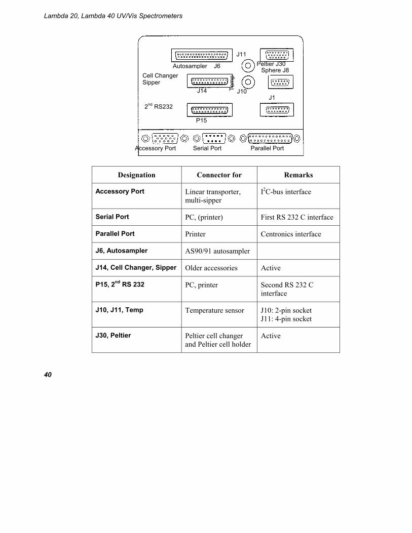
Designation Connector for Remarks
Accessory Port Linear transporter, multi-sipper
I2C-bus interface
Serial Port PC, (printer) First RS 232 C interface
Parallel Port Printer Centronics interface
J6, Autosampler AS90/91 autosampler
J14, Cell Changer, Sipper Older accessories Active
P15, 2nd RS 232 PC, printer Second RS 232 C interface
J10, J11, Temp Temperature sensor J10: 2-pin socket J11: 4-pin socket
J30, Peltier Peltier cell changer and Peltier cell holder
Active
Tem
p
P15
Autosampler J6 Cell Changer Sipper
2nd RS232
Peltier J30 Sphere J8
Parallel Port Serial Port Accessory Port
J14 J10
J11
J1

Accessory Installation
41
J88, Sphere Integrating Sphere Active
J1 Pump for dissolution Active
Accessory Connections
J
J
J
Autosampler J6 Cell Changer Sipper
2nd RS232
Peltier J30 Sphere J8
Parallel Port Serial Port Accessory Port
J14
J10
J1 J11
Tem
p
Autosampler Peltier Cell Holder
Peltier Cell Changer
Temperature Sensor
External Printer
Older Accessories
Linear Transporter
Multi-sipper PC
P15
Lambda 20, Lambda 40 UV/Vis Spectrometers
42
Sample Compartment Cover
Some of the accessories used with the spectrometer require removal of the sample compartment cover.
1. Do this carefully as follows:
2. Open the cover only about 90 degrees to the sample compartment.
3. Carefully slide the cover straight up off both hinges to remove. You install the sample compartment cover, or other accessory cover, by performing this procedure in reverse.
Sample Compartment Front Cover
Some of the accessories used with the spectrometer require removal of the sample compartment front cover.
Do this carefully as follows:
1. Open the sample compartment cover.
2. Carefully slide the cover straight up off both hinges to remove. You install the sample compartment cover, or other accessory cover, by performing this procedure in reverse.
Sample Compartment Window
To remove or install certain accessories, you need to remove the sample compartment windows.
Each window has a magnetic frame and can be easily removed by hand.
Accessory Installation
43
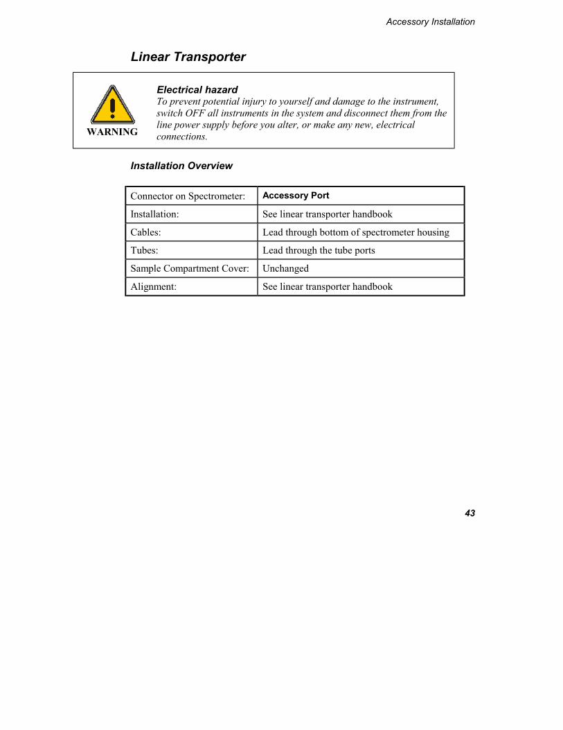
Linear Transporter
WARNING
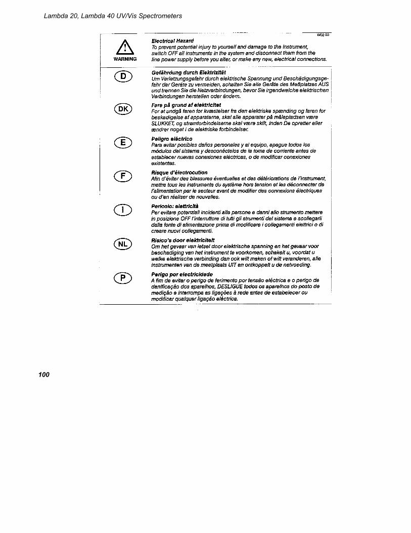
Electrical hazard To prevent potential injury to yourself and damage to the instrument, switch OFF all instruments in the system and disconnect them from the line power supply before you alter, or make any new, electrical connections.
Installation Overview
Connector on Spectrometer: Accessory Port
Installation: See linear transporter handbook
Cables: Lead through bottom of spectrometer housing
Tubes: Lead through the tube ports
Sample Compartment Cover: Unchanged
Alignment: See linear transporter handbook
Lambda 20, Lambda 40 UV/Vis Spectrometers
44
Temperature Sensor
WARNING
Electrical hazard To prevent potential injury to yourself and damage to the instrument, switch OFF all instruments in the system and disconnect them from the line power supply before you alter, or make any new, electrical connections.
Installation Overview
NOTE: When connecting the temperature sensor, align the red mark on the plug with the red mark on the socket. Pull the collar on the plug back to connect/disconnect the plug. Release the collar to secure the plug.
Connector on Spectrometer: Temp J10
Installation: See temperature sensor description
Cables: Lead through the tube ports
Sample Compartment Cover: Unchanged

Accessory Installation
45
Multi-sippers
WARNING
Electrical hazard To prevent potential injury to yourself and damage to the instrument, switch OFF all instruments in the system and disconnect them from the line power supply before you alter, or make any new, electrical connections.
Installation Overview
Connector on Spectrometer: Accessory Port
Installation: See sipper manual
Cables: See sipper manual
Tubes: See sipper manual
Sample Compartment Cover: Unchanged
Figure 9 Multi-sipper, electrical connection
Multi-sipper
Spectrometer
B0167808
Lambda 20, Lambda 40 UV/Vis Spectrometers
46
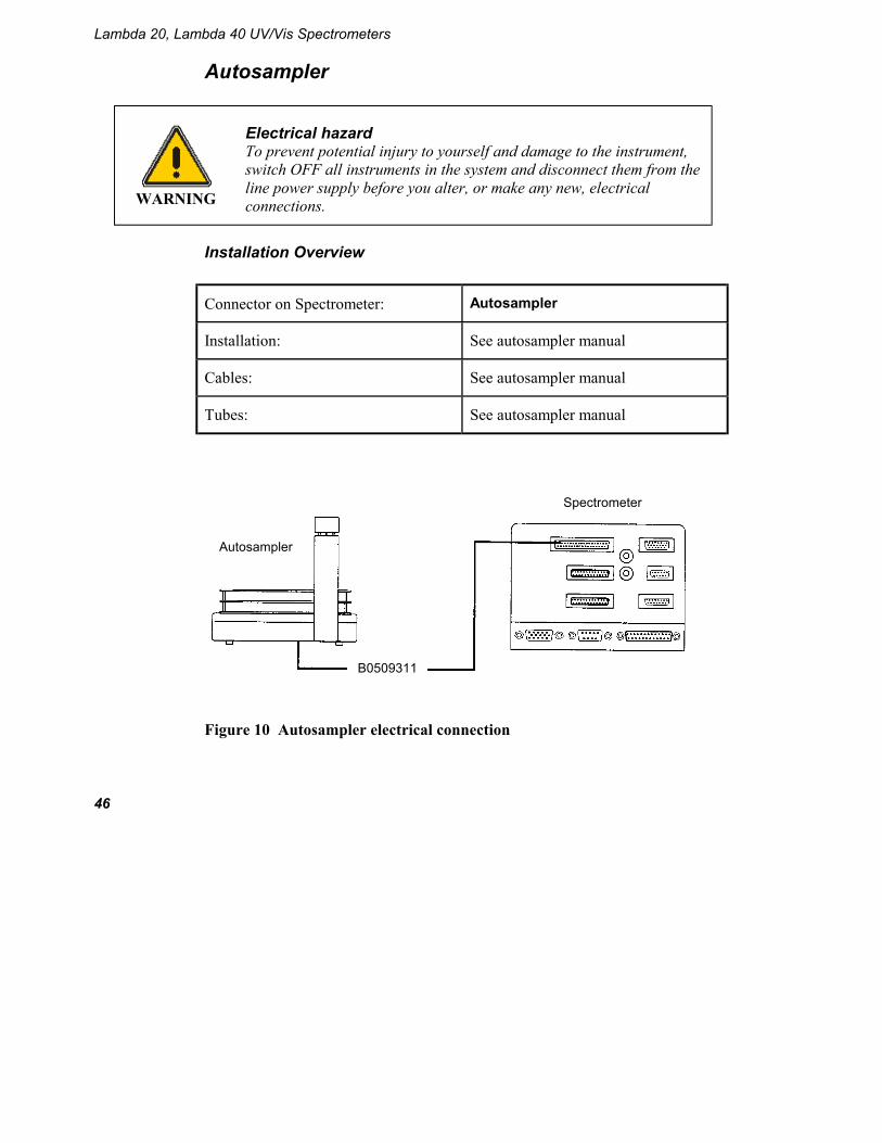
Autosampler
WARNING
Electrical hazard To prevent potential injury to yourself and damage to the instrument, switch OFF all instruments in the system and disconnect them from the line power supply before you alter, or make any new, electrical connections.
Installation Overview
Connector on Spectrometer: Autosampler
Installation: See autosampler manual
Cables: See autosampler manual
Tubes: See autosampler manual
Figure 10 Autosampler electrical connection
Autosampler
Spectrometer
B0509311

Accessory Installation
47
Personal Computer
You can connect a personal computer (PC) to the spectrometer via the Serial Port (RS 232 port).
Make sure that the Serial Port (RS 232 port) is configured for use with a PC (default), see Super User method RS232 PORT CONFIG.
To operate the spectrometer via the PC, you additionally require a PerkinElmer UV software package, for example, UV WinLab, PECSS. Ask your PerkinElmer service representative for more details.

Lambda 20, Lambda 40 UV/Vis Spectrometers
48

Maintenance 5


Maintenance
51
Maintenance
Obtaining Service
All internal servicing of the instrument should be performed by a PerkinElmer service representative or similarly authorized person.
Please contact your local PerkinElmer sales or service office to obtain service.
Maintenance procedures that you can perform yourself are described in this chapter.
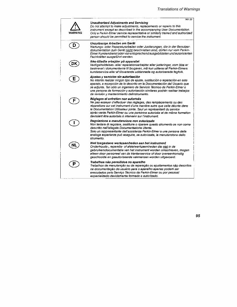
WARNING
Unauthorized Adjustments and Servicing Do not attempt to make adjustments, replacements or repairs to this instrument except as described in the accompanying User Documentation. Only a PerkinElmer service representative or similarly trained and authorized person should be permitted to service the instrument.
Daily Care
The instrument is constructed with high quality components and requires little maintenance other than to keep it clean and free of dust.
To protect the optical system from dust and fumes, you should keep the sample compartment cover closed except for when you are carrying out work in the compartment.
The sample compartment windows should always be installed.
Lambda 20, Lambda 40 UV/Vis Spectrometers
52
You should observe the following care routine to maintain your instrument in good condition:
• Immediately clean all spilled materials from the affected area and wipe it dry with lintless paper or cloth. If you have to wipe the sample compartment windows, make sure you do not introduce scratches. Sample windows are optical components and you should handle them in the sampe way as high quality cells.
• Do not leave samples, particularly those given to fuming or evaporation, in the sample compartment for longer than necessary.
• If any type of sample handling system is installed and portions of it are left in the sample compartment (such as a sipper and flowcell), make certain that the system is cleaned at the end of the working day. Generally, such systems should be filled with deionized water when left overnight.
CAUTION
Risk of damage to Optics or Electronics Take care not to spill liquids onto the spectrometer. Expensive damage can result to the optics or electronics if liquids are spilled and run inside the instrument or onto the keyboard.
Cleaning the Sample Compartment
You must clean the sample compartment every time anything is spilled into it. This preserves the matt black finish, and prevents corrosion and contamination.
The standard sample compartment baseplates have drain holes in them to run off spilled liquids to the benchtop underneath the instrument. You can place a sheet of thick filter paper under the instrument, if required.
1. First remove the cell holder or other sample handling accessory from the sample compartment.

Maintenance
53
2. Using a soft cloth and mild laboratory detergent solution, lightly scrub away all foreign material.
3. Using a clean cloth dampened with water, rinse the cleaned surfaces thoroughly.
4. Dry with lint free cloth or tissue.
Sample Compartment Window
Windows are provided with the spectrometer. The window is made of silica and may be used in the entire spectral range of the spectrometer.
The window seals the sample compartment and thus protects the instrument’s optics from dust and fuming or aggressive samples.
• Generally, the window should be installed at all times.
• The window is an optical component and requires the same care and handling as cells.
• You can remove the window to clean it. The frame is magnetic and can be removed by hand. Windows are most suitably cleaned by wiping them with a soft cloth moistened with ethanol.

Lambda 20, Lambda 40 UV/Vis Spectrometers
54
Use and Care of Cells
Cell Handling
A good spectrometer cell is an optical device, forming a part of the optical system of the instrument with which it is used. It must be accorded the same careful treatment applied to any optical component. Optical faults of a minor nature, scratches, lint, fingermarks, etc. on the optical surfaces can easily introduce substantial analytical errors.
You should observe the following list of cell handling rules to prevent analytical errors and to achieve utmost precision:
• Only hold cells by non-optical surfaces, such as the matt finish surfaces.
• Protect cells from scratches, and never permit them to rub against one another or against other hard surfaces.
• Avoid abrasive, corrosive or stain-producing cleaning agents, and make certain that the exposed surfaces of cells are optically clean.
• Always wipe the optical surfaces of cells dry and free of fingermarks, using a soft cloth or cleaning tissue, just before placing them in the cell holder.
• When measuring cold solutions, always bear in mind that condensation can form on the optical surfaces.
• Make certain no bubbles cling to the inner surfaces of the cell, particularly when handling cold solutions.
• For maximum precision and accuracy, calibrate and test with cells of the same type, and always insert cells into the holders with the same orientation.
Pressure Buildup in Cells
If you are using stoppered cells, observe the following rules to prevent the buildup of internal pressure that could cause the cell to burst:

Maintenance
55
• Only fill the cell so full that the liquid meniscus is just above the radiation beam. The remaining air space in the cell is then adequate to compensate for any slight increase in pressure in the cell during routine operation.
• If, for analytical reasons, it is necessary to fill the cell completely, insert the stopper only lightly so that the liquid in the cell has a chance to expand.
• Do not insert a stopper forcefully into a completely filled cell since this is likely to cause the cell to burst.
• When working at higher temperatures, use a drilled stopper (0.4 mm hole) to allow for expansion in the cell.
Replacing a Lamp
Figure 11 Lamp compartment
Lamp compartment

Lambda 20, Lambda 40 UV/Vis Spectrometers
56
Figure 12 Inside the Lamp Compartment (Baffle removed)
Halogen Lamp Replacement
If the lamp burns out, or if the bulb becomes blackened after prolonged use, you should replace the lamp.
Replacement lamp assemblies are provided complete with prealigned mounts (Part Number B0114620).
Halogen lamp assembly
Lamp energy attenuator
White ceramic connector
Deuterium lamp connector
Deuterium lamp assembly

Maintenance
57
Figure 13 Prealigned Halogen Lamp (B0114620)
WARNING
Electrical Hazard Switch off the spectrometer and remove the plug from the electrical supply before starting with the replacement. Risk of Burns If the old lamp was lighted: allow it to cool before proceeding with the replacement. UV Radiation The lamps emit intense radiation which can damage your eyes. Do not open the lamp compartment when the lamps are on. Do not gaze into a lighted lamp.
1. Switch off the spectrometer and unplug the line power cord.
2. Remove the lamp compartment cover by pressing down the catch and pushing the cover to the left.
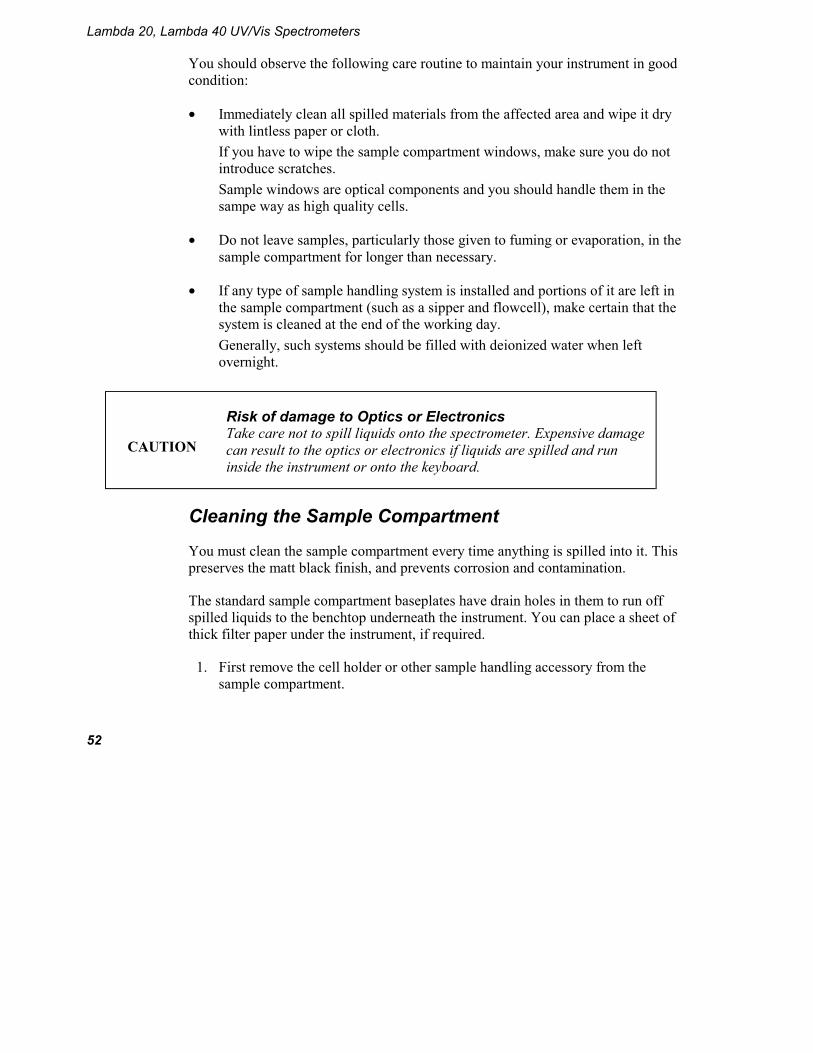
3. Remove the lamp baffle by slackening the thumbscrew for the deuterium lamp and lifting the lamp baffle vertically upward.
Lambda 20, Lambda 40 UV/Vis Spectrometers
58
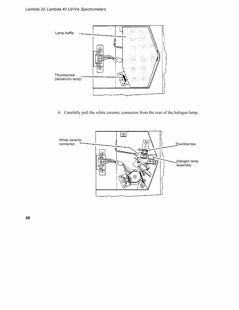
4. Carefully pull the white ceramic connector from the rear of the halogen lamp.
Lamp baffle
Thumbscrew (deuterium lamp)
Thumbscrew
Halogen lamp assembly
White ceramic connector

Maintenance
59
5. Remove the lamp assembly from the bracket by slackening the thumbscrew and pulling the lamp mount vertically upward. Save the thumbscrew for use with the new lamp assembly.
6. Unpack the new lamp assembly, taking care to hold it only by the metal mount to prevent fingermarks on the bulb.
7. Slip the slot at the base of the lamp mount over the stud on the bracket in the lamp compartment and then secure with the thumbscrew.
8. Carefully push the ceramic connector firmly onto the pins on the base of the lamp.
9. Wipe the bulb with a soft cloth moistened with alcohol to remove dirt, since this would otherwise be burned in when the lamp is hot.
10. Replace the lamp baffle using the reverse of the procedure described in step 3.
11. Replace the lamp compartment cover.
This completes the halogen lamp replacement procedure.
Deuterium Lamp Replacement
If the lamp burns out, or indicates falling energy after prolonged use, you should replace the lamp.
Replacement lamp assemblies are provided complete with prealigned mounts (Part Number B2000501).

Lambda 20, Lambda 40 UV/Vis Spectrometers
60
Figure 14 Prealigned Deuterium Lamp Assembly (B2000501)
NOTE: An operating hours counter is incorporated in the red deuterium lamp lead. By means of a gap between the two display bars it is possible to read off the number of hours that the lamp has been in operation. One scale division corresponds to approximately 100 hours.
WARNING
Electrical Hazard Switch off the spectrometer and remove the plug from the electrical supply before starting with the replacement. Risk of Burns If the old lamp was lighted: allow it to cool before proceeding with the replacement. UV Radiation The lamps emit intense radiation which can damage your eyes. Do not open the lamp compartment when the lamps are on. Do not gaze into a lighted lamp.
1. Switch off the spectrometer and unplug the line power cord.
2. Remove the lamp compartment cover by pressing down the catch and pushing the cover to the left.
3. Remove the lamp baffle by slackening the thumbscrew for the deuterium lamp and lifting the lamp baffle vertically upward.
Operating Hours Counter

Maintenance
61
4. Unplug the deuterium lamp connector from the terminal board by squeezing in the two lugs at each side of the connector and carefully pulling the connector vertically upward.
5. Remove the lamp assembly from the bracket by slackening the thumbscrew and pulling the lamp mount vertically upward. Save the thumbscrew for use with the new lamp assembly.
Lamp baffle
Thumbscrew (deuterium lamp)
Deuterium lamp connector
Deuterium lamp assembly

Lambda 20, Lambda 40 UV/Vis Spectrometers
62
6. Unpack the new lamp assembly, taking care to hold it only by the metal mount to prevent fingermarks on the lamp window.
7. Slip the slot at the base of the lamp mount over the stud on the bracket in the lamp compartment and then secure with the thumbscrew.
8. Plug the deuterium lamp connector into the socket.
NOTE: The socket in the lamp compartment is asymmetric; the deuterium lamp connector can be inserted in one direction only. Make certain that the connector is the right way round before inserting it. Never attempt to insert the connector by force.
9. Wipe the lamp window with a soft cloth moistened with alcohol to remove dirt, since this would otherwise be burned in when the lamp is hot.
10. Replace the lamp baffle using the reverse of the procedure described in step 3.
11. Replace the lamp compartment cover.
This completes the deuterium lamp replacement procedure.
Lamp Energy Attenuator
An attenuator is located in the lamp compartment between the deuterium lamp and the beam entrance slit.
If required you can decrease or increase the energy by placing the attenuator into, or taking the attenuator out of, the beam.
The attenuator is set at the factory, normally in the out position.

Maintenance
63
WARNING
Electrical Hazard Switch off the spectrometer and remove the plug from the electrical supply before starting with the replacement. Risk of Burns If the old lamp was lighted: allow it to cool before proceeding with the replacement. UV Radiation The lamps emit intense radiation which can damage your eyes. Do not open the lamp compartment when the lamps are on. Do not gaze into a lighted lamp.
Operate the attenuator as follows:
1. Open the lamp compartment.
2. Remove the lamp baffle by slackening the thumbscrew for the deuterium lamp and lifting the lamp baffle vertically upward.
3. Loosen the thumbscrew holding the attenuator in place.
Lamp baffle
Thumbscrew (deuterium lamp)

Lambda 20, Lambda 40 UV/Vis Spectrometers
64
4. Slide the attenuator downwards into the beam.
5. Tighten the thumbscrew.
6. Follow the above procedure in reverse to slide the attenuator out of the beam.
7. Replace the lamp baffle using the reverse of the procedure described in step 2.
8. Close the lamp compartment.
Lamp Alignment Procedure
Due to the prealigned mounts, the alignment of lamps after installation is generally so good that further alignment is not required.
Lamp energy attenuator
Deuterium lamp assembly

Maintenance
65
Changing Fuses
WARNING
Electrical hazard To prevent potential injury to yourself and damage to the instrument, switch OFF all instruments in the system and disconnect them from the line power supply before you alter, or make any new, electrical connections.
The fuses are located in a fuse holder at the rear of the instrument:
Figure 15 Rear view, Fuse Holder
1. Switch off the instrument and remove the line power cord from the electrical supply.
2. Squeeze the two lugs at each side of the fuse holder and gently pull out.
Fuse Holder
Fuse Holder

Lambda 20, Lambda 40 UV/Vis Spectrometers
66
3. Replace the spent fuse with a new one of the same type and rating:
Voltage Standard
100 V – 120 V 6.3 A slow-blow
210 V – 240 V 3.15 A slow-blow
NOTE: The module has two fuses.
4. Replace the fuse holder. Align the lug at the bottom of the fuse holder with the slot in the socket. A click is heard as each lug snaps into place.
NOTE: If you use the correct fuses but the instrument still does not work correctly, or the fuses blow repeatedly, contact your PerkinElmer office or representative.
Maintaining the Internal Printer
The internal printer needs no special maintenance. You only need to:
• Change the printer paper
• Change the printer ribbon
when necessary.
Changing the Printer Paper
1. Lift off and remove the old paper roll.
2. Replace with a new paper roll.
3. Cut square the end of the paper.
4. Carefully feed the end of the paper into the slot at the top of the printer.

Maintenance
67
5. Press 4 Print to feed the paper through the printer until it appears at the front.
Changing the Printer Ribbon
1. Lift off and remove the paper roll.
2. Push in the catch on the printer cover.
3. Carefully lift out the printer.
4. Gently pull the ribbon cassette forwards to remove.
5. Replace with a new one.
6. Replace the printer and printer cover using the reverse of the above procedure.

Lambda 20, Lambda 40 UV/Vis Spectrometers
68

Replacement Parts 6


Replacement Parts
71
Replacement Parts
Supplies, accessories, and replacement parts can be ordered directly from PerkinElmer. PE XPRESS, PerkinElmer’s catalog service, offers a full selection of high-quality ultraviolet, fluorescence, and polarimetry supplies through the Supplies Catalog for Ultraviolet/Visible and Fluorescence Spectroscopy and Polarimetry.
To place an order, request a free catalog, or ask for information:
If you are located within the U.S., call toll free 1-800-762-402, 8 a.m. to 8 p.m. EST. Your order will be shipped promptly, usually within 24 hours.
If you are located outside of the U.S., call your local PerkinElmer sales office.
Lambda 20, Lambda 40 UV/Vis Spectrometers
72
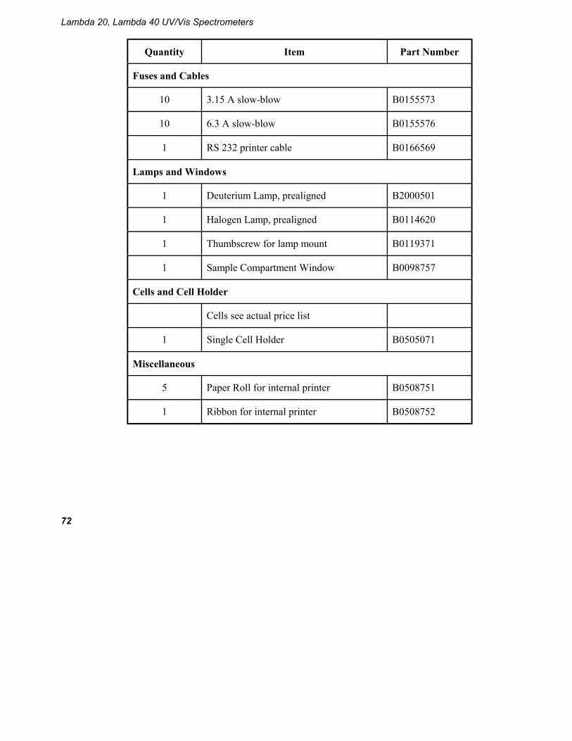
Quantity Item Part Number
Fuses and Cables
10 3.15 A slow-blow B0155573
10 6.3 A slow-blow B0155576
1 RS 232 printer cable B0166569
Lamps and Windows
1 Deuterium Lamp, prealigned B2000501
1 Halogen Lamp, prealigned B0114620
1 Thumbscrew for lamp mount B0119371
1 Sample Compartment Window B0098757
Cells and Cell Holder
Cells see actual price list
1 Single Cell Holder B0505071
Miscellaneous
5 Paper Roll for internal printer B0508751
1 Ribbon for internal printer B0508752

System Description 7


System Description
75
System Description
Features
Figure 16 Lambda 20, 40 Spectrometer Features
Optical System Lambda 20
The Lambda 20 UV/Vis Spectrometer features an all-reflecting optical system. The optical components are coated with silica for durability. A holographic grating is used in the monochromator.
The optical system is depicted schematically in Figure 17.
The monochromator is a holographic concave grating with 1053 lines/mm in the center.
Two radiation sources, a deuterium lamp and a halogen lamp, cover the working wavelength range of the spectrometer.
Keyboard and Display Cover
Lamp compartment
Power switch
Connector panel Sample compartment

Lambda 20, Lambda 40 UV/Vis Spectrometers
76
For operation in the visible (Vis) range, mirror M1 reflects the radiation from the halogen lamp onto source mirror M2. At the same time M1 blocks the radiation from the deuterium lamp.
For operation in the ultraviolet (UV) range, mirror M1 is raised to permit radiation from the deuterium lamp to strike source mirror M2.
Source change is automatic during monochromator slewing.
Radiation from the source lamp is reflected from source mirror M2 through an optical filter on the filter wheel assembly.
A stepping motor drives the filter wheel to be in sychronization with the monochromator.
Depending on the wavelength being produced, the appropriate optical filter is located in the beam path to prefilter the radiation before it enters the monochromator.
Filter change is automatic during monochromator slewing.
From the optical filter the radiation passes through the entrance slit (Slit 1) of the monochromator.
The radiation is dispersed at the grating to produce a spectrum. The rotational position of the grating effectively selects a segment of the spectrum, reflecting this segment through the exit slit (Slit 2) to mirror M3.

System Description
77
Figure 17 Optical Path for Lambda 20
The exit slit restricts the spectrum segment to a near-monochromatic radiation beam.
The slits provide a spectral bandpass of 1 nm, or 2 nm.
From mirror M3 the radiation is reflected onto a beam splitter which allows 50% of the radiation to pass onto plane mirror M4, and reflects 50% of the radiation onto plane mirror M5.
Mirror M4 focuses the radiation beam in the sample cell.
Halogen lamp
Deuterium lamp
Filter wheel
M2
M1
Slit 1
Slit 2
M5
Reference
Sample
M3
Detector
Lens
Lens
Detector M4 Grating
(Monochromator)
Beam Splitter
M = Mirror M1, M4, and M5 = Plane Mirror M2 = Toroidal Mirror M3 = Spherical Mirror

Lambda 20, Lambda 40 UV/Vis Spectrometers
78
The beam then passes through a convex lens onto the photodiode detector.
Mirror M5 focuses the radiation beam in the reference cell.
The beam then passes through a convex lens onto the photodiode detector.
Optical System Lambda 40
The optical system is depicted schematically in Figure 18.
The Lambda 40 UV/Vis Spectrometer features an all-reflecting optical system. The optical components are coated with silica for durability. A holographic grating is used in the monochromator.
The monochromator is a holographic concave grating with 1053 lines/mm in the center.
Two radiation sources, a deuterium lamp and a halogen lamp, cover the working wavelength range of the spectrometer.
For operation in the visible (Vis) range, mirror M1 reflects the radiation from the halogen lamp onto source mirror M2. At the same time M1 blocks the radiation from the deuterium lamp. For operation in the ultraviolet (UV) range, mirror M1 is raised to permit radiation from the deuterium lamp to strike source mirror M2.
Source change is automatic during monochromator slewing.
Radiation from the source lamp is reflected from source mirror M2 through an optical filter on the filter wheel assembly.
A stepping motor drives the filter wheel to be in sychronization with the monochromator.
Depending on the wavelength being produced, the appropriate optical filter is located in the beam path to prefilter the radiation before it enters the monochromator. Filter change is automatic during monochromator slewing.
From the optical filter the radiation passes through the entrance slit (Selectable Slit 1) of the monochromator.
System Description
79
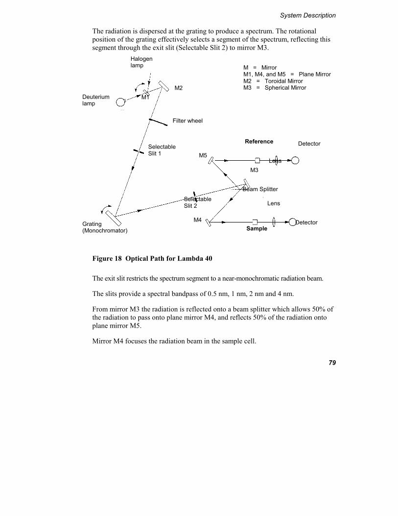
The radiation is dispersed at the grating to produce a spectrum. The rotational position of the grating effectively selects a segment of the spectrum, reflecting this segment through the exit slit (Selectable Slit 2) to mirror M3.
Figure 18 Optical Path for Lambda 40
The exit slit restricts the spectrum segment to a near-monochromatic radiation beam.
The slits provide a spectral bandpass of 0.5 nm, 1 nm, 2 nm and 4 nm.
From mirror M3 the radiation is reflected onto a beam splitter which allows 50% of the radiation to pass onto plane mirror M4, and reflects 50% of the radiation onto plane mirror M5.
Mirror M4 focuses the radiation beam in the sample cell.
Halogen lamp
Deuterium lamp
Filter wheel
M2 M1
Selectable Slit 1
Selectable Slit 2
M5
Reference
Sample
M3
Detector
Lens
Lens
Detector M4 Grating (Monochromator)
Beam Splitter
M = Mirror M1, M4, and M5 = Plane Mirror M2 = Toroidal Mirror M3 = Spherical Mirror

Lambda 20, Lambda 40 UV/Vis Spectrometers
80
The beam then passes through a convex lens onto the photodiode detector.
Mirror M5 focuses the radiation beam in the reference cell.
The beam then passes through a convex lens onto the photodiode detector.

Technical Data 8


Technical Data
83
Technical Data
Lambda 20
General
Type Scanning double-beam spectrometer for the UV/Vis range; with microprocessor and keyboard
Dimensions Width: 650 nm Height: 260 nm Depth: 560 nm
Mass 26 kg approx.
Power requirements 100 V to 240 V AC, 50/60 Hz; 250 VA
Ambient operating temperature 15 ºC to 35 ºC
Humidity range 20% to 80% relative humidity without condensation
Technical Standard In compliance with the requirements for technical instruments stipulated by IEC 1010-1/9.90
Radio interference suppression In compliance with the legal requirements of the EMC directive 89.336/EEC (EN 50 081-1; EN 50 082-1)

Lambda 20, Lambda 40 UV/Vis Spectrometers
84
Optics
Beam center height 15 mm above cell holder bottom
Beam cross-section 1 mm slit ca. 0.6 mm x 9 mm (width x height) 2 mm slit ca. 1 mm x 9 mm (width x height), at focal point of sample and reference beam in sample compartment
Optical pathlength in sample compartment
121 mm
Grating (Monochromator) Holographic concave grating with 1053 lines/mm in the center
Radiation sources Prealigned deuterium and halogen lamps
Detector Photodiodes (One for the sample beam and one for the reference beam)
Abscissa
Wavelength range 190 n to 1100 nm; 0 nm for alignment purposes
Wavelength accuracy ±0.3 nm
Wavelength reproducibility ±0.1 nm
Spectral bandwidth 1 nm or 2 nm (fixed slit)
Lamp change Automatically at 326 nm (selectable over the whole wavelength range, see Super User Factory Configuration)
Scan speeds 7.5, 15, 30 , 60, 120, 240, 480, 960, 1920 and 2880 nm/min
Technical Data
85
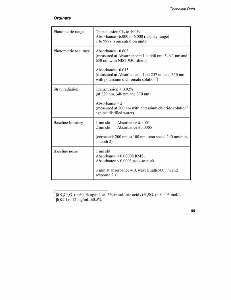
Ordinate
Photometric range Transmission 0% to 100% Absorbance –6.000 to 6.000 (display range) 1 to 9999 (concentration units)
Photometric accuracy Absorbance ±0.003 (measured at Absorbance = 1 at 440 nm, 546.1 nm and 630 nm with NIST 930 filters)
Absorbance ±0.015 (measured at Absorbance = 1, at 257 nm and 350 nm with potassium dichromate solution*)
Stray radiation Transmission < 0.02% (at 220 nm, 340 nm and 370 nm)
Absorbance > 2 (measured at 200 nm with potassium chloride solution† against distilled water)
Baseline linearity 1 nm slit: Absorbance ±0.001 2 nm slit: Absorbance ±0.0005
(corrected: 200 nm to 100 nm, scan speed 240 nm/min, smooth 2)
Baseline noise 1 nm slit: Absorbance < 0.00008 RMS, Absorbance < 0.0003 peak-to-peak
3 min at absorbance = 0, wavelength 500 nm and response 2 s)
* β(K2Cr2O7) = 60.06 µg/mL ±0.5% in sulfuric acid c(H2SO4) = 0.005 mol/L † β(KC1)= 12 mg/mL ±0.5%

Lambda 20, Lambda 40 UV/Vis Spectrometers
86
Baseline stability (drift)
Absorbance < 0.0003 per hour (500 nm, after warmup)
Data Output
Digital port One RS 232 C interface (serial), for connecting a printer or PC; optional second RS 232 C interface
Display Information, parameters and entries are shown on a two line vacuum fluorescence display with 20 alphanumeric characters per line
Methods
Types Timedrive, Scan, Wavelength Program, Concentration Analysis with factor and with Calibration

Technical Data
87
Lambda 40
General
Type Scanning double-beam spectrometer for the UV/Vis range; with four selectable slit widths, microprocessor and keyboard
Dimensions Width: 650 nm Height: 260 nm Depth: 560 nm
Mass 26 kg approx.
Power requirements 100 V to 240 V AC, 50/60 Hz; 250 VA
Ambient operating temperature 15 ºC to 35 ºC
Humidity range 20% to 80% relative humidity without condensation
Technical Standard In compliance with the requirements for technical instruments stipulated by IEC 1010-1/9.90
Radio interference suppression In compliance with the legal requirements of the EMC directive 89.336/EEC (EN 50 081-1; EN 50 082-1)

Lambda 20, Lambda 40 UV/Vis Spectrometers
88
Optics
Beam center height 15 mm above cell holder bottom
Beam cross-section 0.5 mm slit ca. 0.25 mm x 7 mm (width x height) 1 mm slit ca. 0.6 mm x 7.5 mm (width x height) 2 mm slit ca. 1 mm x 7.5 mm (width x height) 4 mm slit ca 2 mm x 7.5 mm (width x height), at focal point of sample and reference beam in sample compartment
Optical pathlength in sample compartment
121 mm
Grating (Monochromator) Holographic concave grating with 1053 lines/mm in the center
Radiation sources Prealigned deuterium and halogen lamps
Detector Photodiodes (One for the sample beam and one for the reference beam)
Abscissa
Wavelength range 190 nm to 1100 nm; 0 nm for alignment purposes
Wavelength accuracy ±0.3 nm
Wavelength reproducibility ±0.1 nm
Spectral bandwidth 0.5 nm, 1 nm, 2 nm, 4 nm (selectable fixed slit widths)

Technical Data
89
Lamp change Automatically at 326 nm (selectable over the whole wavelength range, see Super User Factory Configuration)
Scan speeds 7.5, 15, 30 , 60, 120, 240, 480, 960, 1920 and 2880 nm/min
Ordinate
Photometric range Transmission 0% to 100% Absorbance –6.000 to 6.000 (display range) 1 to 9999 (concentration units)
Photometric accuracy Absorbance ±0.003 (measured at Absorbance = 1 at 440 nm, 546.1 nm and 635 nm with NIST 930 filters)
Absorbance ±0.015 (measured at Absorbance = 1, at 257 nm and 350 nm with potassium dichromate solution*)
Stray radiation Transmission < 0.02% (at 220 nm, 340 nm and 370 nm)
Absorbance > 2 (measured at 200 nm with potassium chloride† solution against distilled water)
Baseline linearity 2 nm slit: Absorbance ±0.0005
(corrected: 200 nm to 100 nm, scan speed 240 nm/min, smooth 2)
* β(K2Cr2O7) = 60.06 µg/mL ±0.5% in sulfuric acid c(H2SO4) = 0.005 mol/L † β(KC1)= 12 mg/mL ±0.5%

Lambda 20, Lambda 40 UV/Vis Spectrometers
90
Baseline noise 2 nm slit: Absorbance < 0.00006 RMS, Absorbance < 0.0002 peak-to-peak
3 min at absorbance = 0, wavelength 500 nm and response 2 s)
Baseline stability (drift)
Absorbance < 0.0003 per hour (500 nm, after warmup)
Data Output
Digital port One RS 232 C interface (serial), for connecting a printer or PC; optional second RS 232 C interface
Display Information, parameters and entries are shown on a two line vacuum fluorescence display with 20 alphanumeric characters per line
Methods
Types Timedrive, Scan, Wavelength Program, Concentration Analysis with factor and with Calibration

Translations of Warnings 9

Translations of Warnings
93
Translations of Warnings
This annex contains translations of the warnings used in this handbook.

Lambda 20, Lambda 40 UV/Vis Spectrometers
94
Translations of Warnings
95

Lambda 20, Lambda 40 UV/Vis Spectrometers
96
Translations of Warnings
97

Lambda 20, Lambda 40 UV/Vis Spectrometers
98

Translations of Warnings
99
Lambda 20, Lambda 40 UV/Vis Spectrometers
100

Translations of Warnings
101

Lambda 20, Lambda 40 UV/Vis Spectrometers
102

Index 10


Index
105
Index
A
Accessory Connections, 41 Accessory Connector Panel, 39 Accessory Installation, 39
Autosampler, 46 General (accessory installation), 39 Linear Transporter, 43 Multi-sippers, 45 Personal Computer, 47 Temperature Sensor, 44
Autosampler, 46
B
Basic Installation, 23 Connecting to the Electrical
Supply, 28 Equipment Provided, 26 Laboratory Requirements, 23 Overview (basic installation), 23 Printer, 35 Single Cell Holder, 29 System Configuration, 27 Unpacking and Inspection, 25
C
Cleaning the Sample Compartment, 52
Connecting up the Printer Configuring an External Printer, 36
D
Deuterium Lamp Replacement, 59
F
Fuses Changing, 65
H
Halogen Lamp Replacement, 56
I
Internal Printer Changing the Printer Paper, 66 Changing the Printer Ribbon, 67 Maintaining, 66
L
Lambda 20 Optical system, 75 Technical data, 83
Lambda 40 Optical system, 78 Technical data, 87
Lamp Alignment, 64 Lamp Energy Attenuator, 62 Linear Transporter, 43
M
Maintenance, 51 Changing Fuses, 65

Lambda 20, Lambda 40 UV/Vis Spectrometers
106
Cleaning the Sample Compartment, 52
Daily Care, 51 Maintaining the Internal Printer, 66 Obtaining Service, 51 Replacing a Lamp, 55 Use and Care of Cells, 54
Multi-sippers, 45
P
Personal Computer, 47 Preface, 19
Documentation, 20 Preparing the Working Area, 23 Pressure Buildup in Cells, 54
R
Replacement Parts, 71 Replacing a Lamp, 55
S
Safety information Electromagnetic Compatibility
(EMC), 10 Safety Information, 7
CSA Compliance, 8 Electrical Protection, 8 Electrical Safety, 8 Environment, 12 Graphic Symbols Used on the
Instrument, 14
IEC 1010 Compliance, 8 UL Compliance, 8 UV Radiation, 14
Setting up the Printer, 35 Connecting an External Printer, 35
Single Cell Holder, 29 Aligning, 31 Fine Alignment, 33 Installing, 30 Minimum Volume Applications, 34
System Configuration, 27 System Description, 75
Features, 75 Optical System Lambda 20, 75 Optical System Lambda 40, 78
T
Technical Data, 83 Lambda 20, 83 Lambda 40, 87
Temperature Sensor, 44 Translations of Warnings, 93
U
Unpacking and Inspection, 25 Use and Care of Cells, 54
W
Warnings Translation, 93