lampf a nuclear research facility - federation of · pdf fileinformal report ic3 ... lampf a...
TRANSCRIPT

LA-6878-MSInformal Report
IC3●P REPRODUCTION
G COPYIS-4 REPORT SECTION
LAMPF
A Nuclear Research Facility
M. Stanley Livingston*
*Consultant. 1005 Cane Large, Santa Fe, NM 87501.
!/’1a amosscientific laboratory
of the university of California‘ ~ LOS ALAMOS, NEW MEXICO 87545
\An Affirmative Action/Equal Opportunity Employer
UC-28 and UC-34
Issued: September 1977
UNITED sTATES
ENERGY RESEARCH AND DEVELOPMENT ADMINISTRATION
CONTRACT W-740 S-ENG. 36

Printed in the United States of America. Available fromNational Technical Information Service
U.S. Department of Commerce5285 Port Royal RoadSpringfield, VA 22161
Price: Printed Copy $5.00 Microfiche $3.00
,Th,. rem,.! . . . vrw.rcd . . . . ..-t . ..1 O( work .ponsar.dh, lhc [.mlrd St. te. (:... rnml.l. S.,!her Ih. t’.itcd Slat.%. . . the t,mted !+.1.. K..rz. Rcw. r, h .nd 1)..,. I.wIIc. ! \d.rm. mtr,,tie., mu. . . . of the,. .mpla. cm. nor .m of their . . . .tr.w.ar.. .. bwmtr.twr., or Ihw cmpl.$ees. m.kei s.}.s, Iw.. I.. .. Dw... . mvlird. or. s.. mc+. . . 1.-s.11$.h,lit, orre.p.ns,lilm (w th. .rc.r. c.. .wmplet.. es.. or ..ef.in.s..1. . . mf.rm. tw.. avp. r.tu.. prod.ti. or pruces. di.clowd. or.. Iw..wI. th.1 N. . . . would ..1 ,.kins. prl.. teh ownedright..
d
9’
LAMPF
A NUCLEAR RESEARCH FACILITY
of
Los Alamos Scientifk Laboratory
Los Alamos, New Mexico
.—
.—-—.——
by
M. -Stanley Livingston
iii


Frontispiece.
v

.
PREFACE
An enterprise of the magnitude of the Meson Physics Facility at Los Alamos Scientific
Laboratory truly involves the efforts of countless persons. Among these, a great many are
essential to the project; without them it could not be completed. In the following pages
some of the most important contributors are named.
Exercising the author’s prerogative, I should here like to emphasize particularly the
contributions of four persons without whom LAMPF could not have come into being:
The two Directors of LASL, under whom LAMPF was conceived and built:
Norris E. Bradbury
Harold M. Agnew
The present Director of LAMPF and MP-Division Leader at LASL:
Louis Rosen
And, finally, a man whose extraordinary vision and talents made him an essential
contributor to this project, to LASL, and to his adopted state of New Mexico; the man for
whom this project was named, to whom I dedicate this work with admiration and ap-
preciation, the late
Senator Clinton P. Anderson.
M. Stanley Livingston
Santa Fe, New Mexico
June 1977
vii

.

CONTENTS
ABSTRACT . . . . . . . . . . . . . . . . . . . . . . . . . . . . . . . . . . . . . . . . . . . . . . . . . . . . . . . . . . . . . . . . . . . . . . 1INTRODUCTION . . . . . . . . . . . . . . . . . . . . . . . . . . . . . . . . . . . . . . . . . . . . . . . . . . . . . . . . . . . . . . . . . 1
Chapter1.
2.
3.
4.
5.
.
6.
ORIGINS AND PRESENT STATUSOF LAMPF . . . . . . . . . . . . . . . . . . . . . . . . . . . . . . 3A. Location . . . . . . . . . . . . . . . . . . . . . . . . . . . . . . . . . . . . . . . . . . . . . . . . . . . . . . . . . . . . . . . . . 3B. Authorization and Construction . . . . . . . . . . . . . . . . . . . . . . . . . . . . . . . . . . . . . . . . . . . . 3C. Linac Performance . . . . . . . . . . . . . . . . . . . . . . . . . . . . . . . . . . . . . . . . . . . . . . . . . . . . . . . . 4
ORGANIZATION . . . . . . . . . . . . . . . . . . . . . . . . . . . . . . . . . . . . . . . . . . . . . . . . . . . . . . . . . . . . 7A. Medium Energy Physics Division . . . . . . . . . . . . . . . . . . . . . . . . . . . . . . . . . . . . . . . . . . . 7B, Users Group . . . . . . . . . . . . . . . . . . . . . . . . . . . . . . . . . . . . . . . . . . . . . . . . . . . . . . . . . . . ..oIo
C. Program Advisory Committee . . . . . . . . . . . . . . . . . . . . . . . . . . . . . . . . . . . . . . . . . . . ...10D. Administrative and Technical Services . . . . . . . . . . . . . . . . . . . . . . . . . . . . . . . . . . . . ..I2E. LAMPF Policy Board . . . . . . . . . . . . . . . . . . . . . . . . . . . . . . . . . . . . . . . . . . . . . . . . . . ...12F. Financial Record . . . . . . . . . . . . . . . . . . . . . . . . . . . . . . . . . . . . . . . . . . . . . . . . . . . . . . . ...12
LAMPF USERS GROUP . . . . . . . . . . . . . . . . . . . . . . . . . . . . . . . . . . . . . . . . . . . . . . . . . . ...15A. Organization and Charter . . . . . . . . . . . . . . . . . . . . . . . . . . . . . . . . . . . . . . . . . . . . . . . ...15B. Incorporation and Officers . . . . . . . . . . . . . . . . . . . . . . . . . . . . . . . . . . . . . . . . . . . . . . ...15C. Technical Advisory Panel.. . . . . . . . . . . . . . . . . . . . . . . . . . . . . . . . . . . . . . . . . . . . . . ...17D. User Working Groups . . . . . . . . . . . . . . . . . . . . . . . . . . . . . . . . . . . . . . . . . . . . . . . . . . ...17
PROCEDURES FOR RESEARCH EXPER.IMENTS . . . . . . . . . . . . . . . . . . . . . . . . . ...23A. Proposals and Approvals . . . . . . . . . . . . . . . . . . . . . . . . . . . . . . . . . . . . . . . . . . . . . . . ...23B. Financial Support for Users . . . . . . . . . . . . . . . . . . . . . . . . . . . . . . . . . . . . . . . . . . . . . ...24C. LAMPF Support . . . . . . . . . . . . . . . . . . . . . . . . . . . . . . . . . . . . . . . . . . . . . . . . . . . . . . . ...24D. Scheduling and Equipment Committees . . . . . . . . . . . . . . . . . . . . . . . . . . . . . . . . . ...25E. Funding for Experiments . . . . . . . . . . . . . . . . . . . . . . . . . . . . . . . . . . . . . . . . . . . . . . . ...26
THE ACCELERATOR . . . . . . . . . . . . . . . . . . . . . . . . . . . . . . . . . . . . . . . . . . . . . . . . . . . . ...27A. Preaccelerators and Ion Sources . . . . . . . . . . . . . . . . . . . . . . . . . . . . . . . . . . . . . . . . . ...27B. Drift-Tube Linac . . . . . . . . . . . . . . . . . . . . . . . . . . . . . . . . . . . . . . . . . . . . . . . . . . . . . . . . .31C. Side-Coupled-Cavity Linac. . . . . . . . . . . . . . . . . . . . . . . . . . . . . . . . . . . . . . . . . . . . . ...35D. Beam Switchyard . . . . . . . . . . . . . . . . . . . . . . . . . . . . . . . . . . . . . . . . . . . . . . . . . . . . . . ...38E. Control System . . . . . . . . . . . . . . . . . . . . . . . . . . . . . . . . . . . . . . . . . . . . . . . . . . . . . . . . ...38F. Linac Performance . . . . . . . . . . . . . . . . . . . . . . . . . . . . . . . . . . . . . . . . . . . . . . . . . . . . . ...41
RESEARCH INSTWLATIONS . . . . . . . . . . . . . . . . . . . . . . . . . . . . . . . . . . . . . . . . . . . . . . . 43A. Meson Physics Area-Experimental Area A . . . . . . . . . . . . . . . . . . . . . . , . . . . . . ...43
1. Low-Energy Pion Channel (LEP) . . . . . . . . . . . . . . . . . . . . . . . . . . . . . . , . . . . . ...432. Energetic Pion Channel and Spectrometers (EPICS) . . . . . . . . . . . . . . . . . . ...453. Stopped Muon Channel (SMC). . . . . . . . . . . . . . . . . . . . . . . . . . . . . . . . . . . . . . ...504. Pionand Particle Physics Channel (Pg) . . . . . . . . . . . . . . . . . . . . . . . . . . . . . . ...50
ix

B. Nucleon Physics Laboratory —Experimentalkea B . . . . . . . . . . . . . . . . . . . . . . . . 521. Neutron Beams . . . . . . . . . . . . . . . . . . . . . . . . . . . . . . . . . . . . . . . . . . . . . . . . . . . . . . . 52
2. External Proton Beam (EPB) . . . . . . . . . . . . . . . . . . . . . . . . . . . . . . . . . . . . . . . ...52C. High-Resolution Spectrometer (HRS) . . . . . . . . . . . . . . . . . . . . . . . . . . . . . . . . . . . . ...52D. Thin Target Area . . . . . . . . . . . . . . . . . . . . . . . . . . . . . . . . . . . . . . . . . . . . . . . . . . . . . . ...55
<
E. Nuclear Chemistry Facilities . . . . . . . . . . . . . . . . . . . . . . . . . . . . . . . . . . . . . . . . . . . . ...55F. High-Intensity Applications Areas . . . . . . . . . . . . . . . . . . . . . . . . . . . . . . . . . . . . . . . ...58 =
1. Radioisotope Production Facility . . . . . . . . . . . . . . . . . . . . . . . . . . . . . . . . . . . . ...582. Radiation Effects Facility . . . . . . . . . . . . . . . . . . . . . . . . . . . . . . . . . . . . . . . . . . . ...603. Neutrino Facility . . . . . . . . . . . . . . . . . . . . . . . . . . . . . . . . . . . . . . . . . . . . . . . . . . . . . . 60
7. PRACTICAL APPLICATIONS . . . . . . . . . . . . . . . . . . . . . . . . . . . . . . . . . . . . . . . . . . . . . . . . 63
A. Biomedical Facility . . . . . . . . . . . . . . . . . . . . . . . . . . . . . . . . . . . . . . . . . . . . . . . . . . . . . . . 63
B. Experimental Projects . . . . . . . . . . . . . . . . . . . . . . . . . . . . . . . . . . . . . . . . . . . . . . . . . . ...641. Radioisotope Production Facility . . . . . . . . . . . . . . . . . . . . . . . . . . . . . . . . . . . . . . . 68
2. Radiation Damage Studies.. . . . . . . . . . . . . . . . . . . . . . . . . . . . . . . . . . . . . . . . . . . . 68
3. Neutron Beams . . . . . . . . . . . . . . . . . . . . . . . . . . . . . . . . . . . . . . . . . . . . . . . . . . . . ...684. Muonic XRays for Analysis. . . . . . . . . . . . . . . . . . . . . . . . . . . . . . . . . . . . . . . . . ...68
C. Technology Transfer . . . . . . . . . . . . . . . . . . . . . . . . . . . . . . . . . . . . . . . . . . . . . . . . . . . . . . 69
1. Side-Coupled-Cavity Linacs for X-Ray Systems . . . . . . . . . . . . . . . . . . . . . . . . . . 692. Electro-Surgical Tool . . . . . . . . . . . . . . . . . . . . . . . . . . . . . . . . . . . . . . . . . . . . . . . ...693. Thermal Treatment of Tumors . . . . . . . . . . . . . . . . . . . . . . . . . . . . . . . . . . . . . . ...694. Tumor Diagnostic Studies . . . . . . . . . . . . . . . . . . . . . . . . . . . . . . . . . . . . . . . . . . ...69
D. Weapons Pulsed Neutron Facility . . . . . . . . . . . . . . . . . . . . . . . . . . . . . . . . . . . . . . . ...69
REFERENCES . . . . . . . . . . . . . . . . . . . . . . . . . . . . . . . . . . . . . . . . . . . . . . . . . . . . . . . . . . . . . . . . . . . 71
APPENDIXARTICLES OFINCORPORATION OFUSERS GROUP ANDBYLAWS OF LAMPF USERS GROUP . . . . . . . . . . . . . . . . . . . . . . . . . . . . . . . . . . . . . ...73
.

LAMPF — A NUCLEAR RESEARCH FACILITY
by
M. Stanley Livingston, Consultant
ABSTRACT
This report presents a description of the recently completed Los AlamosMeson Physics Facility (LAMPF) which is now taking its place as one of themajor installations in this country for the support of research in nuclearscience and its applications. Descriptions are given of the organization ofthe Laboratory, the Users Group, experimental facilities for research andfor applications, and procedures for carrying on research studies. Results ofthe research program are published elsewhere.
——————— ——— ——— —— __
1. INTRODUCTION
The name LAMPF describes a nuclear researchfacility at the Los Alamos Scientific Laboratory. Itutilizes a high-intensity 800-MeV linear acceleratorwhich provides beams of protons and a variety ofsecondary particles and radiations, of which themost useful are positive and negative pions, Thefacility includes targets, beam-handling devices,and the instrumentation for research experiments.A sketch of the installation is shown in Fig. 1.LAMPF is primarily a research laboratory fornuclear physics; it is also of major interest toradiochemists, biologists, and solid-state physicists.It provides facilities for important applications inmedicine, in isotope production, in the structure ofmaterials, and in defense science ,1*2LAMPF is anational research facility, available to allprofessionally qualified members of the scientificcommunity.
On completion, the facility was named the Clin-ton P. Anderson Meson Physics Facility. Followinginitial operation of the linac at 800-MeV energy inJune 1972, and the start of a preliminary researchprogram in August, it was dedicated, and Senator
Anderson was honored, at a ceremony on Septem-ber 29.
A beam intensity of 100-gA average was achievedby August 1976. During the latter half of 1976 thenumber of scientists participating in experiments
totalled 310, of which 86 were from LASL. Otherswere from universities, other national laboratories,and from hospitals and medical centers. Even atthis early stage of operations, it is possible to claim asignificant success for this facility, which showspromise of becoming a major research installation.The success is due primarily to the continuing ef-forts of the LAMPF staff, ably led by the Director,Louis Rosen.
This report is a description of the operatingfacility, intended for general informational pur-poses. Features covered in the report include thebasic properties of the facility and of the severalbeam channels, the organization of the laboratoryand of the Users Group, and a description of theprocedures for initiating a research program. It ishoped that this report will provide a useful overviewof this new and important research facility as itmatures and joins with other laboratories in thiscountry in providing support for research in nuclearscience and its applications.
1

:0awaaza:
“m,auaasawmI
2=
-b!4
zoK1-
ii
J
IIm
“;L
.j?
.!Q
2
v
CHAPTER 1
2ORIGINS AND PRESENT STATUS OF LAMPF
A. Location
The LAMPF linac and research facility is locatedon Mesita de Los Alamos, a long, narrow mesa southof the main plateau on which the town of LosAlamos is situated. The top of the mesa is essen-tially level, providing an excellent site for the half-mile-long linear accelerator, with wide and deeparroyos on both sides and at the eastern end. Themesa is formed of tuff, a soft, low-density volcanic-ash rock. The main linac is in a tunnel formed bycutting a deep trench in the rock, with backfillabove for shielding.
LAMPl? is operated within a division of the LosAlamos Scientific Laboratory and has benefitedfrom the skills and technical expertise accumulatedat LASL over its 30 years as a research and weaponslaboratory. A significant distinction is that LAMPFis planned as an open laboratory available toqualified scientists from across the nation or fromforeign countries, while LASL continues a large ef-fort in weapons research under strict (Class A)security control. LAMPF is located outside theLASL security gates; the only controls required arethose for identification of authorized personnel andthe protection of government property (Class Bsecurity).
A valuable bonus for the visiting research workeris the town of Los Alamos, an ususually well-planned and attractive site for family living, withexcellent schcmls, churches, shopping centers, andother facilities.
B. Authorization and Construction
The Los Alamos Meson Physics Facility was con-ceived in 1962 by a small group of LASL scientists,mostly from the Physics Division, under theleadership of Louis Rosen. A study group headed byD, E. Nagle, whose other members were Austin
McGuire, D. C. Hagerman, and E. A. Knapp,became active in design planning in 1962 and pre-pared the first tentative proposal. The concept wasshepherded through the design and authorizationphases from 1962-66 by this same group and was
constructed with funds allocated by the U.S.Atomic Energy Commission during 1966-72. The
story of the development of this facility is given in aLASL report “Origins and History of the Los AlamosMeson Physics Facility, ” LA-5000, June 1972.3
A preliminary proposal by the LASL staff wassubmitted to the Division of Physical Research ofthe Atomic Energy Commission in December 1962,which announced the Lm Alamos plans to enter thefield of meson-producing accelerators. In August1963, the LASL group prepared a “ConstructionProject Data Sheet’” entitled “Los Alamos MesonPhysics Facility, ” which was submitted to the AECby the LASL administration and which proposedschedules for construction and cost estimates. Theacronym “LAMPF,” coming from the title of thedocument, soon became the popular name of thefacility. This early design work was supported bythe LASL administration using funds primarilycoming from the AEC Division of Military Applica-tions.
Competition was severe for supporting funds formeson-producing accelerators during 1962 to 1964.6The only available source was the U.S. AtomicEnergy Commission (although later the NationalScience Foundation did support the rebuilding of anexisting installation at Columbia University whichoperates at considerably lower intensities). Aproposal for a similar proton Iinac was submitted byYale University, 0 based on the same evidenceavailable to LASL. A proposal for a high-intensityisochronous cyclotron came from the Oak RidgeNational Laboratory,’ and a plan for a negative-ion(H- ) sector-focused cyclotron was proposed by agroup in the Physics Department of the Universityof California at Los Angeles.8
3
The LASL proposal came closest to meeting therecommendations of the “Bethe Panel” Report.s TheBethe Panel, chaired by Professor Hans Bethe ofCornell University, was appointed in 1963 by thethen OffIce of Science and Technology to advise theGovernment on the needs for high-intensity,medium-energy (<1.0 GeV) accelerators whichcould produce mesons. As a result of their Report, anew budget entity was formed by the AEC to sup-port the medium-energy field, and the rec-ommendations of the Bethe Panel were adopted asAEC policy. So the LASL proposal was approved forsupport by the AEC in early 1964.
Construction funds were not obtainable on shortnotice, but in April 1%4 the Physics Research Divi-sion of the AEC made a fund of $500000 available toLASL for a study to define the scope, design basicengineering features, and develop reliable cost es-timates. These funds allowed the LASL group to ex-pand staff, intensify the model program, employcommercial firms to start architect/engineeringstudies of buildings and site requirements, designand estimate costs of radio-frequency powersystems, and study the problem of computer con-trol. This engineering and cost study was completedby September 1964, and from these data a revised“Construction Project Data Sheet’”” was presentedto the AEC on October 30, 1964. The cost estimatewas $55 000000, and the time for construction es-timated as six years. This became the basic cost andtime estimate for construction.
Detailed design and construction of the LAMPFfacility started with authorization of the first con-struction funds by the Congress in the FY-1966budget. Further amounts were authorized in suc-cessive years, but during several years were reducedbelow the requested amounts. These postponementsof funds delayed completion of some parts of the in-stallation and increased the cost. Major construc-tion funds became available in October 1968. Con-struction of the Equipment Test Laboratory beganin early 1968. A fkst unit of the linac housing, theInjector Building, was started in early 1969. By thistime the design of the accelerator itself was essen-tially complete and construction contracts had beenplaced covering most of the linac components. Con-
struction of the tunnel and of the radio-frequencypower cubicles spaced along the tunnel was com-pleted to meet the scheduled dates for equipmentinstallation in all cases. The last unit of the build-
ing complex to be specified and built was the hous-ing for the target areas and experimental areas atthe end of the Iinac.
The Iinac was brought into initial operation at ~800 MeV with a low-intensity beam on June 9, 1972,within the time schedule and the revised cost es-timate of $57000000. .
C. Linac Performance
Progress during the subsequent developmentalstate of the linac can be illustrated by the followinglist of the more important events:
June 9, 1972First beam of 800-MeV protons obtained with afew pA intensity at the end of the Iinac.
August 1972First experiments started at low-beam intensitymostly of the satellite type.
March 28, 1973First ion (H-) beam accelerated to 800 MeV.
July 15, 1973Proton beam of 250 MeV and 0.5-pA-averageintensity obtained in Area B.
August 26, 1973Proton beam of 447 MeV and 0.6-pA-averageintensity used in Area A. Beams of p+, e+, x+,and p+ separated for the first time.
April 1974Pion beam channel in the Biomedical Facilityoperable.
January-December 1974Increasing use of beams for research: 70 experi-ments given beam time; 1600 shifts of researchoperation; 40 000-wA h delivered to experi-ments.
September 24, 1974Announcement of “Great Shutdown, ” startingin late December 1974, to improve linac inten-
sity, radiation harden the main beam line com-ponents, add shielding, and install more ex-
perimental installations.
4

A summary of the progress in research made dur-ing 1974 is listed:
r 1. A total of 66 experiments were mounted.Operation of these experiments and analysis of theresults proceeded throughout the year..
2. Simultaneous delivery of beam was made toeight experiments.
3. The Line A beam stop location was used forinitial data on three neutrino experiments (Experi-ments 24, 31, 38).
4. Muonic x-ray studies were made on severaltargets to determine quadruple and hexadecapolemoments, and to give accurate charge radii (Experi-ments 7, 166, 163).
5. Pion-produced charge-exchange reactionswere produced and radioactive products weremeasured (Experiment 102).
6. Inelastic pion scattering on Zr and C wasstudied (Experiments 191, 180).
7. Liquid tritium (T) was produced and usedas a target for pion-capture reactions (Ex-periment 50).
8. Measurements were made of pion total crosssections at low energy (Experiment 2).
9. Measurements were made of scattering ofpions by H at low energy (Experiment 96).
The “Great Shutdown” extended through August1975. Developments of the linac and facilitiesaccomplished during this time can be summarized:
1. improvements of quantity, cooling, and con-figuration of shielding in switchy~d andmain beam run,
2. radiation hardening of target cells with addi-tion of shielding,
3. improved facilities for handling radioactivesamples and equipment,
4. repair and replacement of some faulty drift-tube bellows in 100-MeV Iinac,
5. improved alignment of drift-tube linac to in-crease beam acceptance,
6. resurvey of main linac alignment withlevels, transit, and taut wires,
7. correction of phase errors in main linac dueto misalignments,
8. installation of many new experiments in theexperimental areas.
A major result of the shutdown was an increase ofbeam intensity. Routine operation at 1OO-PAaverage beams of H+ ions was achieved by August1976. The H- ion beam diverted to Area B was alsoincreased in intensity, to 6-PA average. Spinningtarget wheels were developed for target locations A-1 and A-2, capable of handling intensities of lCQ PA,and water-cooled windows have been installed atBeam Stop A-6. By May 1977, the facility was inproduction at 150-PA average, and one run wasmade at 300 PA with a duration of over one hour.These developments are a good indication thatLAMPF will eventually reach its design intensity ofl-mA average H+ beam at 800-MeV energy, at -6%duty cycle. Even at present intensities the availablebeam power (energy X intensity) exceeds thatavailable at any other accelerator. Proton beam in-tensity exceeds the sum of intensities from allproton accelerators of energy above the pionthreshold. The potential usefulness of these high in-
tensities has hardly been explored and promisesresults of major importance.
Another important accomplishment of the shut-down was the installation of many new experiments,with beam control equipment and adequate shield-
ing for higher intensities. The use of multiplebranching beams allows more experiments to be runsimultaneously. Typically, 10 or more experimentsreceive beam simultaneously utilizing the availablefacilities. Nearly 100 experiments in various stagesof installation or operation have been set up in themany possible locations.
By June 1977 the Facility had been developed tofull capacity for research use, if not to ultimate fullintensity. A total of over 1000 scientists were mem-bers of the Users Group and had submitted over 300proposals for experiments. The operations phasenow starting (Summer 1977) should be a mostproductive period.
5


(-
CHAPTER2
4ORGANIZATION
A. Medium Energy Physics Division
The LAMPF facility is operated by the MP-Division (Medium Energy Physics) of the LosAlamos Scientific Laboratory. Louis Rosen isDivision Leader, and also Director of LAMPF,appointed by the Director of LASL. The MP-Division is a broader organizational entity thanLAMPF and can be assigned wider responsibilitiesthan the meson physics facility, although in practicethe two organizational entities overlap almost com-pletely. To illustrate the distinction: Rosen isresponsible for all research activities of the staff ofthe MP-Division, whether they are performed atLAMPF or elsewhere. The linear accelerator beamis also put to other uses than for the LAMPF
research facilities. For example, the WeaponsNeutron Research area uses a fractional beamdiverted from the linac through a tunnel into a sep-arate building where research is carried on by otherLASL Divisions.
The staff of the facility hold assigned positions ofresponsibility within either the MP-Division Office(MP-DO) or in one of the twelve groups: MP-1, MP-2, MP-3, MP-4, MP-7, MP-8, MP-9, MP-10, MP-11,MP-12, MP-13, and MP-14. They can also be said tohold parallel positions on the LAMPF staff. Buttheir official positions are as members of the MP-Division. (Note that other groups, the missing num-bers, were active during design and construction butwere phased out when LAMPF became an operatingfacility.)
The name LAMPF has become a simplificationuseful in describing the facility and the arrange-ments of the laboratory. It covers the scientificresearch functions and those aspects of its opera-tions dealing with the scientific users. In 1968-69when scientists from outside LASL were meeting toplan the Users Group, a clear distinction was made
between LAMPF, which was to be an openlaboratory providing facilities for outside scientists,and LASL, the existing laboratory, part of whichwas classified and part of whose mission wasweapons development. The potential users believedthat a substantial autonomy of LAMPF withinLASL must be achieved if it were to attractqualified scientists and develop a significantresearch program. With this in mind the users wroteinto their charter the arrangements by which theusers would deal with the “Director” of LAMPF, andthe extent to which the “Director” would accepttheir guidance on scientific matters and the researchprogram, This title is not normally given to divisionleaders at LASL. The Director of LASL has accept-ed these arrangements as proper to ensure the scien-tific success of the new research facility. In so doing,he has accepted the existence of a “LAMPF” entitydistinct from the MP-Division and has authorizedthe use of the title of “Director” for the leader ofLAMPF.
In his capacity as the scientific leader of themeson facility, it is the responsibility of the LAMPFDirector to approve and authorize the researchprograms to be carried out at LAMPF. At suitableintervals he calls for proposals for research experi-ments from the scientific users. These proposals aresubmitted to him and, with the assistance of hisoperations and support staff and with the adviceand recommendations of the Program AdvisoryCommittee (PAC) which he appoints, the Directorauthorizes and schedules the research experiments.
One method of describing the organization is anoutline form based on the several groups, with stafftitles and assignments, as given in Table I. Anotherdescription is an organization chart of MP-Divisionwhich, though somewhat simplified, shows some ofthe interrelations between groups; such a chart isshown in Fig. 2.
—
7

TABLE I
ORGANIZATION OF MP DIVISION
June 1977
MP-DO — Medium Energy Physics Division Office1. MP-Division Leader, L. Rosen (also LAMPF Director)2. Alternate MP-Division Leader, D. E. Nagle3. Associate Division Leader for Operations, D. C. Hagerman
a. Operations Staffb. Accelerator Committeec. Scheduling Committee
D. C. Hagerman, ChairmanL. E. AgnewD. R. F. CochranT. M. PutnamD. E. NagleA. A. BrowmanS. P. Koczan
4. Associate Division Leader for Experimental Areas, Lewis Agnew5. Associate Division Leader, E. A. Knapp6. Users Group Office
a. Administrative Services, E. Dunnb. Users Liaison, D. R. F. Cochran
7. Assistant Division Leader for Planning Budgets, R. F. Warner8. Assistant Division Leader for Experiment Evaluation, Special Problems, Secretary to
PAC, D.R.F. Cochran9. Assistant Division Leader for Safety, T. M. Putnam
MP-1, Electronic Instrumentation and Computer Systems, H. S. Butler, Group Leader
MP-2, Operations, J. Bergstein, Group Leader
MP-3, Practical Applications, J. N. Bradbury, Group Leader
MP-4, Nuclear and Particle Physics, D. E. Nagle, Group Leader
MP-7, Experimental Areas, L. E. Agnew, Group Leader
MP-8, Engineering Support, E. D. Bush, Group Leader
MP-9, Accelerator Development, R. A. Jameson, Group Leader
MP-10, EPICS and HRS, H. A. Thiessen, Group Leader
MP-11, Accelerator Support, J. D. Wallace, Group Leader
MP-12, Injector Systems, R. R. Stevens, Jr., Group Leader
MP-13, Beam Line Physics, R. Macek, Group Leader
MP-14, Pion Generator for Medical Irradiations, D. A. Swenson, Group Leader
8

Iw
“-1
,
1
I
—
T—
——
TIi
II
9

B. Users Group
Another aspect of the organization is the UsersGroup, which is independent of the official structureof the LASL laboratory but operates as a service tothe scientific users from other institutions. TheUsers Group has its own organization and Board ofDirectors and is incorporated under the laws of theState of New Mexico pertaining to nonprofit cor-porations. It appoints a Technical Advisory Panel(TAP) to work closely with the LAMPF supportstaff on plans for the experimental program, tostudy new capabilities and support systems, and tomake recommendations to the Director of LAMPF.
The LAMPF organization provides offices, ad-ministrative liaison, secretarial services, and allnecessary facilities to the Users Group, to assistthem in accomplishing their purposes. The directorof LAMPF accepts advice and suggestions from theTechnical Advisory Panel whenever practicable,and accepts the Board of Directors of the UsersGroup as the official spokesmen for the scientificusers of the LAMPF facility. Because of its impor-tance in the operations of the facility, the UsersGroup and its activities are described in more detailin a following chapter.
C. Program Advisory Committee
The Program Advisory Committee (PAC) is theprimary determinant of scientific policy and scien-tific use of LAMPF. This committee examinesresearch proposals, recommends acceptance, rejec-tion, or modification on the basis of scientific meritand feasibility, and recommends priorities for
proposals found acceptable. Its responsibility coversall proposals which require substantial beam time orother LAMPF resources. It is the indispensableright arm of LAMPF management insofar as thescientific program is concerned.
The PAC is appointed by the Director of LAMPFin his capacity as scientific leader of the researchfacility. He also acts as Chairman of the PAC, asrecommended in the guidelines set down in theUsers Group. Membership consists of the LAMPFDirector, his Deputy, and at least nine additionalmembers of the scientific community appointed for
three-year terms. The PAC includes two nonvotingrepresentatives of the Division of Physical Research
of the U.S. Energy Research and Development Ad-
ministration (ERDA) and two from the NationalScience Foundation.
Half or more of the scientific members appointed _to the PAC are selected from nominations made bythe Board of Directors of the Users Group. Membersare chosen with an eye toward maintaining a ~suitable balance in geographical and institutionaldistribution and in represent at ion of the variousscientific disciplines to be pursued at LAMPF. Thepresent membership of the PAC is given in Table II.
A large fraction of the work of the PAC is done bysubcommittees of three to five members; each mem-ber of the PAC typically serves on two subcommit-tees. Subcommittees cover the following specialareas:
Nuclear ChemistryLow-Energy Pions (LEP)lNeutrinosHigh-Resolution Spectrometer (HRS)Pion and Particle Physics (P’)External Proton Beam (EPB)Nucleon Physics (Line B)Stopped Muon Channel (SMC)Energetic Pion Channel and Spectrometers
(EPICS)It can be noted that each of the above areas isassociated wit h a specific experimental beam line.The subcommittees act as referees to recommendpriorities, schedule beam time and available ex-perimental equipment for this beam line, and to ad-vise on the needs for additional equipment and in-strumentation.
There are in addition two special subcommitteeswhich are advisory to the PAC and do notnecessarily include PAC members. These are:
Solid-State Physics Committee (5 members)Biomedical Program Advisory Committee
(8 members)The Biomedical Committee deals entirely withproblems in the biological and medical fields. Theyexamine research proposals in these fields and rec-ommend approval or other action, Their ret- -ommendations are reported, via the PAC, to theDirector, LAMPF, for decision and action.
The PAC meets four times a year on the call of the “
Chairman, to consider recently submitted researchproposals. The subcommittees usually meet first asworking groups, to study proposals in their fields
10

TABLE 11
MEMBERSHIP OF THE PROGRAM ADVISORY COMMITTEE ( 1977)
Louis Rosen, Director of LAMPF, ChairmanD. E. Nagle, MP-4, LAMPF, DeputyG. A. Cowan, CNC-DO, LASL, Secretary
Stephen Adler, Institute for Advanced Study, Princeton UniversityGeorge Bell, T-10, LASLFelix Boehm, California J.nstitute of Technology.John C. Cramer, University of WashingtonRobert A. Eisenstein, Carnegie-Mellon UniversityGerald T. Garvey, Argonne National LaboratoryLee Grodzins, Massachusetts Jnstitute of TechnologyB. G. Harvey, Lawrence Berkeley LaboratorytJohn Huizenga, Nuclear Structures Laboratory, University of RochesterAlan D. Krisch, University of MichiganIra L. Morgan, Columbia Scientific Laboratories, Austin, TXMichael J. Saltmarsh, Oak Ridge National LaboratoryEllis Steinberg, Argonne National LaboratoryHerbert Steiner, Lawrence Berkeley LaboratoryMorton M. Sternheim, University of MassachusettsErich Vogt, University of British ColumbiaRobert E. Welsh, College of William and Mary.Joseph Weneser, Brookhaven National Laboratory
George Rogosa, Division of Physical Research,U. S. Energy Research and Development Administration
Marcel Bardon, National Science FoundationHoward Pugh, National Science Foundation
L. E. Agnew, MP-7, LAMPFA. A. Browman, MP-DO, LAMPFI). R. F. Cochran, MP-DO, LAMPFD. C. Hagerman, MP-DO, LAMPFE. Knapp, P-DO, LASLS. Koczan, MP-8, LAMPFT. M. Putnam, MP-DSO, LAMPF
ex-officiononvoting

and make recommendations to the PAC in generalmeet ing, for action on these proposals.
D. Administrative and Technical Services
The administrative chores of LAMPF are handledin the MP-Division Office (MP-DO) under the
guidance of Rosen, MP-Division Leader, assist-ed by a staff to whom the several functions are as-signed as indicated in Table I. One major function isoperation of the accelerator, a complex electronicsystem requiring a highly trained organization ofexperts for planning, scheduling, maintenance, andcontinuous development. Another aspect is coor-dination of the research programs of the scientificusers with the requirements and capabilities of theaccelerator and its beam facilities. User coordina-tion includes evaluation of experimental proposals,resolution of special problems, and scheduling ofbeam use. An office which centralizes User Groupactivities and provides administrative services ispart of the responsibilities of the Division Office.The essential functions of budget planning andfiscal reporting are also the direct responsibilities ofthe Division Leader.
Most of the groups listed under MP-1 throughMP-14 provide supervision of technical aspects ofthe Facility. Some are directly related to the linacitself, some cover beam-handling support systemsand some deal with permanently located ex-perimental facilities. However, titles of groups donot restrict the activities of individual group mem-bers. Many cross group boundaries to solve overlap-ping problems. The basic responsibility of all thetechnical staff is to expedite wherever possible theresearch programs of the user scientists. Some of themost essential groups are those in direct support ofthe experiments. Furthermore, the challenge of us-ing pions for the irradiation of human cancer hasadded much incentive to the support staff. Themost recently formed group, MP-14, is aimed at thedesign and development of compact meson-producing accelerators which, hopefully, could beused for a wider approach to the treatment of can-cer. This work is supported by the National CancerInstitute.
E. LAMPF Policy Board
The LASL Director has his own independentsource of information and advice on the policy,plans, and performance of LAMPF. This is the ‘
LAMPF Policy Board (LPB) which was initiated in1968 by the then Director, Norris Bradbury. ‘
Meetings were held at approximate six-month inter-vals during the design and construction phase.Since 1971 the Board reports to the present Director,Harold Agnew, and meetings are held annuallyat the Director’s call. The present membership ofthe LPB is:
H. L. Anderson, University of Chicago, Chair-man
Robert E. Anderson, School of Medicine, Un-iversity of New Mexico
Peter D. Barnes, Carnegie-Mellon UniversityE. V. Hungerford, University of HoustonT. A. Tombrello, California Institute of
Technology
The Policy Board has consistently emphasizedthe National Facility aspect of LAMPF and theneeds of the scientific users of the facility. Its advicehas been helpful in promoting the development ofthe Users Group, in minimizing security restrictionsfor foreign users and visitors, in procurement ofsuitable housing for users, and in several otheraspects. It has had significant influence instrengthening theoretical support in nuclearphysics, both in the LASL T-Division and atLAMPF.
F. Financial Record
LAMPF is one of the few large acceleratorfacilities supported by the AEC for which the cost ofconstruction was essentially as initially estimated.The design and construction costs as estimated inthe Construction Project Data Sheet of October 30, -1964 were $55000000. A postponement by the Con-gress of the dates of authorization of funds beyondthe planned and scheduled dates resulted in -rearrangement of the schedule and an increase inthe cost estimate by $1 000000. The linac was
12

brought into preliminary operation on June 9, 1972within this revised cost estimate of $56000000. Cer-tain additions beyond the scope of the original
. plans and estimate, which were authorized duringthe next two years, brought the total to $57000000.A breakdown of construction costs for major4LAMPF components is shown in Table III.
The budgets for operation and for capital equip-ment and other costs associated with research in-strumentation have also been within the initiallyplanned range. There have been no budgetary sur-prises, either during the construction or in theoperations phase. A record of the operations costs
for the years prior to and following completion isgiven in Table IV, which also shows projections ofmajor items into the future.
The early success of the LAMPF program, itsfiscal responsibility, and the ambitious plans forresearch and applications have resulted in recogni-tion where it counts — in the budget authorizations.Although it is always difficult to persuade theFederal budget authorities to support a programwith rising cost estimates, the record of LAMPFshows that the budgets have met most of the needsof this growing laboratory which has shown a rapidlyincreasing level of research activity.
TABLE III
SUMMARY OF CONSTRUCI’ION COSTSFOR MAJOR LAMPF COMPONENTS
Design of Buildings and SiteConstruction of Buildings and SiteDesign of AcceleratorConstruction of rf SystemConstruction of Accelerator StructuresConstruction of Injector SystemConstruction of SwitchyardInstrumentation and ControlsOther Equipment Items
TOTAL
$330500028650497
411200065740726157795
71942642065062950893
323811
$57000000

.5w
cm
&mbt-m
‘i
8{mo
8{m
GL-m$
14

.
CHAPTER 3
LAMPF USERS GROUP
The LAMPF Users Group was started in 1968 —four years before the scheduled date for initialoperation — in order to provide a channel of com-munication between the Users and LAMPFmanagement in planning the research facility. A
general meeting of potential users was called forJune 20, 1968, timed during a regional meeting ofthe American Physical Society at Los Alamos. Rep-resentatives of 70 universities and laboratories fromoutside LASL participated. Members of the LASLstaff had anticipated the need for a users organiza-tion and supported it heartily. At this meeting com-mittees were named to prepare a Charter, tonominate officers and to plan for a second meeting.
A. Organization and Charter
At the second Users Group meeting heldJanuary 16, 1969, a Charter” prepared in the in-terim was adopted, an Executive Committee ofseven members was elected as prescribed in theCharter, and a Chairman delegated. The Charterdescribed the membership of the Users Group as“open to practicing scientists and engineers, ” clearlyallowing anyone with a valid interest in working atLAMPF to become a member. The Director ofLAMPF appointed a Liaison Officer, L. E. Agnew,to act as secretary of the Executive Committee andto assist the new organization in all possible ways.At the first Executive Committee meeting aTechnical Advisory Panel (TAP) was appointed “tocollaborate with the staff of LAMPF in devising newexperimental facilities and evaluating futuredevelopments. ” The Executive Committee alsostarted a newsletter, to be edited by the Liaison Of-ficer and published regularly as a report to themembership. The first newsletter was publishedMarch 21, 1969, with others at quarterly intervals insucceeding years.
Annual meetings of members of the Users Groupare normally held in October or November of eachyear, for election of officers and transaction of otherbusiness. Statistical summaries of the LAMPF UserGroup activities are presented in Table V.
B. Incorporation and Officers
A decision to incorporate the Users Group wastaken at the November 1972 annual meeting, and aset of By-Laws was approved. The incorporation of
the LAMPF Users Group, Inc., became effective onJanuary 1, 1973. The officers and Executive Com-mittee of the Users Group elected for the year 1973under the previous Charter became the “Board ofDirectors” of the Corporation. This Board of Direc-tors consists of a Chairman, Chairman-elect, PastChairman, and four other members elected by themembership. Two new members are elected eachyear for terms of two years, and one new Chairman-elect is elected each year for a term of three years.The Chairman-elect succeeds to the office of Chair-man at the end of one year and to that of past Chair-man at the end of two years. Elections to open posi-tions on the Board of Directors are conducted bymail ballot prior to the annual meeting of the mem-bership, which is held between October 15 andNovember 30 of each year. All terms of office beginJanuary 1 of the year following election.
The Board of Directors meets as often as requiredto carry on the business of the Users Group. ALiaison Officer is appointed to the Board by theDirector, LAMPF, who also serves as Secretary tothe Board and as Editor of the Users Bulletin. In or-der to illustrate the scientific quality of the UsersGroup, as well as for historical reasons, lists of thosemembers elected to Executive Committees underthe Charter during 1969 to 1972, and to the Boardsof Directors and Officers elected under the Articlesof Incorporation By-laws from 1973 to 1976, are

Date
SpringFallSpringFallSpringFallSpringFallSpringFallSpringFallFallFallJanuary
‘1’ABLli V
SUMMARIES OF LAMPF USER ACI’IVITIES
Total Numberof Users
196919691970197019711971197219721973197319741974197519761977
173325364461510604630
737
830846871992
1036
Number LASL Total NumberUsers Proposals
509099
100121155167 1
1178 1
1
188 1
180 1
183 :189 c
198 ,
STATUS OF LAMPF RESEARCH PR$3POSALS
January 1977
Completed 64Active (approved, deferred, resubmitted) 191Inactive (rejected, withdrawn, combined) 70
TOTAL 325
PARTICIPANTS IN USERS GROUP
January 1977
U. S. UniversitiesLASLNational or Government LaboratoriesForeignIndustryHospitals and Medical CentersHonorary
410198114156579110
1036
7397
115138142162181197241
325
TOTAL
16

given in Table VI. For reference purposes the Arti-cles of Incorporation of the LAMPF Users Group,and the By-laws, are attached as the Appendix.
.
C. Technical Advisory Panel.
Under the By-laws, a Technical Advisory Panel
(TAP) is appointed by the Board of Directors tocollaborate with the staff of LAMPF in devising newexperimental facilities and evaluating futuredevelopments. The TAP consists of 12 memberseach appointed for two years, with 6 new membersadded each year. Members of the Board, and aLiaison Officer appointed by the Director, LAMPF,are Members Ex-0~/icio. Present Membership isgiven in Table VII.
The TAP is the major working arm of the UsersGroup and the primary agency to transmit the needsof the Users to the attention of the LAMPF staff.They work in close cooperation with LAMPF anduse their efforts to expedite the technical activitiesof the supporting staff.
D. User Working Groups
An important activity initiated by the ExecutiveCommittee as early as 1969 was a study program
based on “Working Groups” of users, to studyspecific design problems which required analysisand development. Working Group meetings werecalled by LAMPF staff planners or by users andwere scheduled and arranged by the Liaison Officer.During the following years these Groups becamelarger and more active; new groups were activated
as new areas of interest developed. Chairmen as-signed to each group were responsible for callingmeetings, assigning tasks and reporting results.
Recommendations made by the Working Groupswere reported in the Newsletter. Dozens of workingsessions of such groups helped to define thespecifications and properties of the specialized in-struments being developed by the LAMPF technicalstaff in prep= ation for experimental use. Thesestudies have had a major impact on increasing thescope and quality of the research installations builtat LAMPF. To illustrate the breadth of interest andthe intense activity of users in these cooperativestudies, a listing is given in Table VIII of some ofthese meetings, with their topics and chairmen, asthey were published in the Newsletters.
17

TABLE VI
USERS GROUP EXECUTIVE COMMITTEES ANDBOARDS OF DIRECTORS
l!)(y)
Chairman, Harry Palevsky, Brookhaven National LaboratoryChairman-Elect, D. A. Lind, University of ColoradoMembers
R. P. Haddock, University of California at Los AngelesA. M. Poskanzer, Lawrence Berkeley LaboratoryH. B. Willard, Case Western Reserve University
I,iaison Officer, L. E. Agnew, LAMPF
1970
Chairman, R. P. Haddock, University of California at Los AngelesChairman-elect, G. C. Phillips, Rice UniversityMembers
I. L. Morgan, University of Texasi-l. A. Naumann, Princeton UniversityB. J. Zeidman, Argonne National Laboratory
Liaison Officer, L. E. Agnew, LAMPF
1971
Chairman, G. C. Phillips, Rice UniversityChairman-elect, K. M. Crowe, Lawrence Berkeley LaboratoryMembers
l’. D. Barnes, Carnegie-Mellon UniversityM. J. Jakobson, University of Montana.J. E. Simmons, LASL
Liaison Officer, L. E. Agnew, LAMPF
1972
Chairman, K. M. Crowe, Lawrence Berkeley LaboratoryChairman-elect, M. J.. Jakobson, University of MontanaMembers
G. tJ. Igo, University of California at Los AngelesL. C. Northcliffe, Texas A&M UniversityChaim Richman, LASL
I.iaison Officer, L. E. Agnew, LAMPF
197:3
Chairman, M. J. Jakobson, University of MontanaChairman-elect, V. W. Hughes, Yale Universityl~ast Chairman, K. M. Crowe, Lawrence Berkeley Laboratory
MembersR. E. Anderson, University of New Mexico Medical SchoolR. ,J. Macek, LASLS. E. Sobottka, University of VirginiaH. B. Willard, Case Western Reserve University
Liaison Officer, L. E. Agnew, LAMPF
18

.
.
TABLE VI
(CONTINUED)
1974Chairman, V. W. Hughes, Yale UniversityChairman-elect, H. L. Anderson, Fermi InstitutePast Chairman, M. J. Jakobson, University of MontanaMembers
R. E. Anderson, University of New Mexico Medical SchoolR. M. Ekberg, University of California, Santa BarbaraR. J. Macek, LASLS. E. Sobottka, University of Virginia
Liaison Officer, L. E. Agnew, LAMPF
1975Chairman, H, L. Anderson, Fermi InstituteChairman-elect, D. A. Lind, University of ColoradoPast Chairman, V. W. Hughes, Yale UniversityMembers
L. E. Agnew, LAMPFJ. C. Allred, University of HoustonR. E. Anderson, University of New Mexico Medical SchoolR. M. Eisberg, University of California, Santa Barbara
Liaison Officer, H, H. Howard, LAMPFSecretaryflreasurer, D. R. F. Cochran, LAMPF
1976Chairman, D. L. Lind, University of ColoradoChairman-elect, H. B. Willard, Case Western Reserve UniversityPast Chairman, H. L. Anderson, University of ChicagoMembers
L. E. Agnew, LAMPFJ. C. Allred, University of HoustonB. M. Preedom, University of South CarolinaPaul Todd, University of Pennsylvania
Liaison Officer, H. H. Howard, LAMPFSecretary~easurer, D. R. F. Cochran, LAMPF
1977Chairman, H. B. Willard, Case Western Reserve UniversityChairman-elect, J. C. Allred, University of HoustonPast Chairman, D. L. Lind, University of ColoradoMembers
B. M. Preedom, SIN, Villigen, SwitzerlandPaul Todd, Pennsylvania State UniversityR. C. Minehart, University of VirginiaR. A. Rebka, Jr., University of Wyoming
Liaison Officer, H. H. Howard, LAMPFSecretary/Treasurer, D. R. F. Cochran, LAMPF
19

TABLE VII
TECHNICAL ADVISORY PANEL (TAP), 1977
Liaison Officer, H. H. Howard, LAMPF
1977
Nuclear Chemistry . . . . . . . . . . . . . . . . . . . . . . . . . . .. A. A. CarettoNucleon Physics Laboratory, NPL . . . . . . . . . . . . . . George GlassHigh-Resolution Spectrometers, HRS . . . . . . . . . . . . . . . G. I. Igollxperimental Facilities . . . . . . . . . . . . . . . . . . . . . . William MayesNeutrino Facility . . . . . . . . . . . . . . . . . . . . . . . . . . .. Peter NemethyMuon Facility . . . . . . . . . . . . . . . . . . . . . . . . . . . . . . ..R. J. Powers
1978Biomedical . . . . . . . . . . . . . . . . . . . . . . . . . . . . . . . . . .. E. L. GilletteSolid-State Physics . . . . . . . . . . . . . . . . . . . . . . . . . . .. A. N. Golandl’olarized Beams . . . . . . . . . . . . . . . . . . . . . . . . . . .M. McNaughtonPion and Particle Physics, PS. . . . . . . . . . . . . . . ..R. C. MinehartEnergetic Pion Channel and Spectrometers . . . ..R..J. PetersonLow-Energy Peons . . . . . . . . . . . . . . . . . . . . . . . . . . . . .. Klaus Ziock
TAP Subcommitteeslmng-Range Planning . . . . . . . . . . . . . . . . . . . . . . . . . . .. D. A. LindComputer Services . . . . . . . . . . . . . . . . . . . . . . . . . . .. R. E. ChrienCryogenic Targets . . . . . . . . . . . . . . . . . . . . . . . . . .. R. P. HaddockNew Muon Channel . . . . . . . . . . . . . . . . . . . . . . . . . . V. W. Hughes
.
20

TABLE VIII
woRKIN~ GROUP MEETINGS OF USERS
Topics.
January 1970April 1970
January 1971March 1971April 1971May 1971
June 1971July 1971
AND LAMPF STAFF
—
April 1973
July 1973
November 1973
April 1974
July 1969 Biomedical ApplicationsAugust 1969 Stopped Muon Channel
Pion ChannelsHigh-Resolution Proton SpectrometerNucleon-Nucleon FacilityMedium Energy Particle PhysicsIsotope SeparatorPion and Particle Physics (P’)Energetic Pion Channel and
Spectrometer (EPICS)High-Resolution Spectrometer (I-IRS)Nuclear Chemistry
(At Gordon Conference)EPICSHRSP’EPICSBiomedicalRadiation BiologyNuclear ChemistryP’Nucleon Physics LaboratoryLow-Energy PionsStopped MuonsEPICSPion TherapyEPICSHRSTheory Pion-Nucleus Scattering
(Summer School)LEP ChannelHRSNucleon Physics Laboratory (NPL)EPICSBiomedical FacilitiesP’Slow Muon ChannelNuclear ChemistryComputing FacilitiesRadiation DamageNeutrino FacilityHRSHRS (Washington, D. C.)EPICS (Washington, D. C.)
Chairmen
W. Langham and D. E. GroceV. W. Hughes and H. VogelP. C. GugelotB. J. ZeidmanJ. E. SimmonsP.A.M. Gram and P. C. GugelotB. DropeskyP.A.M. GramP. D. Barnes
N. TanakaE. Norris
P. D. BarnesN. TanakaP.A.M. GramP. D. BarnesW. LanghamP. ToddB. DropeskyP. C. GugelotJ. C. HopkinsJ. Amato and R. L. BurmanV. W. HughesB. J. ZeidmanD. E. GroceS. E. SobottkaHarry PalevskyH. Feshback
K.O.H. Ziock and B. M. PreedomN. SteinD. Brown and J. E. SimmonsR. J. Peterson and S. E. SobottkaP. ToddG. Rebka and R. MinehartR. B. PerkinsB. DropeskyH. S. ButlerW. GreenK. LandeHarry Palevsky and E. FlynnE. FlynnH. A. Thiessen

TABLE VII1
(CONTINIJED)
November 1974
February 1975April 1975June 1975November 1975
April 1976August 1976November 1976
January 1977
Radiation DamageLEPStopped Muon ChannelNucleon Physics LaboratoryEPICSNuclear ChemistryHRSEPICSHRSEPICSIsotopes and DiagnosticsBiomedical FacilitiesEPICSFStopped MuonsRadiation DamageNeutrino FacilityNucleon Physics LaboratoryComputing FacilitiesLEP ChannelHRSNuclear ChemistryHRSEPICSComputer FacilitiesEPICSP’Stopped MuonsRadiation DamageNucleon Physics LaboratoryNeutrino FacilityBiomedical FacilitiesLow-Energy PionsNuclear ChemistryHRSPolarized Beam
W. V. GreenB. M. PreedomR. B. PerkinsP. R. BevingtonS. E. SobottkaB. DropeskyE. FlynnH. A. ThiessenD. K. McDaniel
- H. A. ThiessenH. A. O’BrienE. L. GilletteR. J. PetersonE. V. HungerfordB. SheraW. V. GreenK. LandeB. DieterleH. S. ButlerB. PreedomD. K. McDanielsB. DropeskyG. J. IgoR. EisensteinH. S. ButlerR. A. EisensteinJ. C. AllredBrooks SheraW. V. GreenB. E. BonnerPeter NemethyE. L. GilletteE. E. GrossC. J. OrthG. J. IgoE. P. Chamberlain
22

.
CHAPTER 4
PROCEDURES FOR RESEARCH EXPERIMENTS
A. Proposals and Approvals
Proposals for research at LAMPF are submittedin writing to the Director of LAMPF, at such timesas he calls for proposals, following the form and con-tent described in the LAMPF Users Handbookizpublished November 1974. Information is alsoavailable through the Users Office at LAMPF.
The proposal should indicate the scientific pur-poses and objectives of the experiment, an analysisof the expected data rates and backgrounds, an in-dication of the results and precision expected, an es-timate of when the experiment will be ready, an es-timate of the running time and beam requirementsand a statement about the necessary auxiliaryequipment and support required from LAMPF. Alist of experimenters should be provided, with basicprofessional information sufficient to judge their ex-perience and qualifications, and with an indicationof the extent of participation of each.
Collaboration between outside research workersand the LAMPF research staff is encouraged by theLAMPF administration. Places on existing researchteams can be made available to those desiring togain pertinent experience. Each proposal should in-dicate the extent of collaborative participationplanned and the magnitude of the several contribu-tions.
A preliminary processing of each proposal iscarried out by the LAMPF Director’s Office, and allproposals which compete significantly for beamtime or LAMPF resources are subjected to carefulstudy and evaluation. However, the Direct or, withadvice from the LAMPF administration, mayauthorize and schedule certain experiments such assatellite experiments which make no significant de-mand on LAMPF resources or for beam time. On oc-casion he may reorder priorities, or even providebeam time to a new experiment in response tochanges in the experimental situation or newdevelopments in physics. In the event of two or more
proposals for essentially similar experiments, theLAMPF Director and his staff will make an effort toarrange for collaboration between the groups in-volved and request a revised proposal.
Proposals are numbered in sequence in the orderreceived; this is a permanent identification numberfor future action and scheduling. On receipt, theLAMPF Office makes multiple copies of theProposals, for distribution to members of theProgram Advisory Committee (PAC). One copy isfiled in the LAMPF library for general availability.
Each Proposal when submitted must include aone-page Summary which gives the title, names andaffiliations of participants, and a statement of thepurpose of the research and the method ofprocedure. These Summaries are published in thenext available Newsletter; they serve to informother Users of the planned experiment and avoidduplication. Lists of the Summaries are available inthe Users Office and serve a useful purpose inproviding an overall survey of the research program.
The primary basis for accepting or rejectingproposals and assigning beam time is the scientificmerit of the research and the qualifications of theexperimenters, as judged by the Director of LAMPFafter careful evaluation and solicitation of rec-ommendations by selected experts. His chief sourceof advice is from the Program Advisory Committee.His appointments to the PAC are based to a largeextent on the recommendations of the Board ofDirectors of the Users Group.
The Program Advisory Committee, meeting withthe Director, studies the proposals submitted andmakes its recommendations, including the amountof beam time to be allocated. A proposal may berejected or the Committee may advise certainmodifications. Minutes are kept of all meetings andactions of the PAC, including all recommendationsand the reasons for them. The PAC transmits itsrecommendations to the Director. On the basis ofthese recommendations and his own staff studies,
23

the Director makes his decisions and transmitsthem to the applicants, including the authorizationof beam time. If a proposal is rejected, or modifica-tions suggested, the reasons are given in the letter.
For each approved experiment the LAMPF Chiefof Operations appoints an Experiment Coordinator.He works with the experimenters in planning thedetails of the experiment, such as location in thebeam line, dates and times of occupancy, support bythe LAMPF technical groups, estimates of costs,running time, etc. The coordinator becomes theprima~ channel of information between the ex-perimenters and the LAMPF organization. Hefollows the progress of the experiment, arranges forappropriate assistance, and sees that the work isboth planned and performed in compliance withLASL operational and safety requirements.
During the Annual Meeting of the Users Group inOctober 1970, the LAMPF Director issued the firstcall for proposals for research experiments to be per-formed at LAMPF when it became operational. Thecall was made 20 months before the anticipated dateof the fiist operation at 800 MeV to allow adequatetime to consider and process the applications, andto provide time for experiments to be designed,built, and mounted in place. Information on thefacilities and beam channels to be available at thestart of operations, and the procedures for prep-aration of proposals had been published in apreliminary version of. the Users Handbook (LA-4586-MS). The date of this first call was for April1971 but later was extended to June 1971. TheProgram Advisory Committee (PAC) was called intoservice in June to make initial recommendations.The preliminary decisions of the Director on thisfirst group of 70-odd proposals were announced inthe Newsletter dated July 1971.
The number of proposals has grown steadily withtime since the first call, along with an increase inthe number of users. These numbers are listed inTable V, along with other statistical informationrelative to the research use of LAMPF.
B. Financial Support for Users
Users from Universities and other institutionsmust provide the bulk of the financial support fortheir scientists from sources other than LAMPF.Salaries and expenses of the participants, travel and
shipping expenses, and rental for local housing,must be paid by the outside users. Users are expect-ed to provide their own special experimental ap-paratus, detector systems and the associated cir- .cuitry, often including a trailer to house the controland data analysis electronics. In general, any instru-ments or equipment not available at LAMPF must -be supplied by the User. If Users utilize LASL ser-vices for the design, fabrication, and maintenance ofspecialized equipment, or computing time, they areexpected to reimburse LASL for costs. Charge rates,including direct expense and distributed overheadcosts, are those currently in effect at LASL and ap-ply equally to internal LASL groups for the sameservices.
Approved and scheduled experiments require ad-vance planning and estimates of costs. Experimen-ters should work with the Experiment Coordinatorassigned by LAMPF in estimating expenses, in-cluding a reasonable contingency, and arrange for apurchase order from their home institutions to coverthe estimated expense in advance of their needs.
C. LAMPF Support
All major costs of operation of the accelerator aresupported through the annual LAMPF budgets;Users are not levied charges for beam time. TheLAMPF organization maintains a staff effort to ex-plore and implement improvements of the ac-celerator and experimental facilities. It is LASLpolicy that all members of the LAMPF researchstaff devote roughly 50 per cent of their time to theimprovement of the facility and the technical sup-
port of the users.Certain major experimental facilities are provided
by LAMPF as part of the general facility. These in-
clude several large instruments such as the HighResolution Spectrometer (HRS) and the spec-trometers in the EPICS beam channel. They also in-clude beam analysis magnets in the beam channelswhich provide separated beams of pions, muons, ornucleons. Some experiments are designed to utilize -these “in house” instruments and are assigned timein the appropriate beam channels.
Users have access to a pool of equipment, theLAMPF Electronics Equipment Pool (LEEP). Thetotal inventory in stock by Spring 1977 was over2300 items of capital equipment with a total value of
24

over $1 700000. These include, as a descriptivesample: oscilloscopes, power supplies, voltmeters,amplifiers, pulse generators, delay circuits,magnetic tape drives, coincidence circuits, coun-ter/timers, scalers, registers, etc. Users may requestloans from this stock for the duration of their experi-ment. Requests are authorized by the SchedulingCommittee and are provided by the LEEP Commit-tee. This LEEP Committee is appointed by theDirector of LAMPF to manage the stock of equip-ment and assignments to experimental groups. In-ventory control is based on computer listing andanalysis. The Users Group, through its TechnicalAdvisory Panel (TAP), may recommend items forpurchase and inclusion in the LEEP pool.
The LAMPF support staff erects and installs ap-propriate shielding and enclosures for the elec-tronics and control station of the experiment. Theexperimenter is encouraged to provide his owntrailer with electronics installed. However, sometrailers may be made available by LAMPF. LAMPFwill provide power, telephone, signal and controlwiring to the control station. On-line computingfacilities are available in limited supply, and a ser-vice organization can provide maintenance. It is alsothe intention of the LASL administration to provideadequate office, laboratory, and set-up space forusers’ needs.
A modest amount of direct financial support forexperiments which have been assigned beam timemay be provided by LAMPF in the form of anallowance prorated according to the amount ofscheduled beam time. This allowance may be usedto cover shop work, minor stores and consumables,and machine time at the LASL Central ComputingFacility (CCF).
Certain other types of support are provided byLAMPF. They staff and run the Users Office whichkeeps records, publishes a Users Handbook and aquarterly Newsletter, arranges for housing accom-modations and other needs of the Users. Graduatestudents assisting in experiments have been offeredpart-time jobs as Technical Assistants at LAMPF,to help defray living expenses and broaden their ex-perience.
In consideration of the fact that the researchfacility is supported by Federal funds, each outsideuser must accept certain responsibilities. One re-quirement is that each non-LASL user sign an ap-propriate Guest Patent Agreement, which should be
compatible with prior agreements the user may
have with his home institution. Another require-ment is that the user be properly registered with theLASL Personnel Office and accept any essentialrestrictions required for the control of personnel orgovernment property. The Director of LASL will en-deavor to minimize restrictions on the participationof foreign scientists, in conformity with presentregulations. In 1974 the Atomic Energy Commissiondesignated LAMPF as a “Category B“ Facility,which liberalizes the approval of non-Soviet foreignvisitors; such visitors require approval one week inadvance from LASL. Soviet bloc visitors still needprior approval by ERDA which can be obtainedthrough the LASL Security Office.
D. Scheduling and Equipment Committees
The technical problems of planning for andscheduling the use of the beams for experiments arehandled by the LAMPF Scheduling Committee(LSC), This Committee of six members is appoint-ed by the Director, LAMPF. The present chairmanis D. C. Hagerman, Chief of Operations. This grouptakes recommendations of the Program AdvisoryCommittee for each approved experiment, and fitsthem together into a schedule of use, with respect totime-sharing, beam intensity, beam energy, andother characteristics of the linac. The PAC dividesits work between several subcommittees, each con-sidering the experiments directed toward one of thebeam channels. So the LSC also can simplify itstask by considering the beam channels separately.The scientists and/or the Engineering Coordinatorof each experiment being considered are usuallycalled into the LSC meetings considering their re-quirements. The LSC also considers the needs of theseveral beam lines and provides an overall scheduleof time sharing. Meetings of the LSC are held eachweek or more often if needed. Present membershipof the LAMPF Scheduling Committee is:
D. C. Hagerman, Chief of Operations, Chair-man
L. E. Agnew, MP-7 Group LeaderH. S. Butler, MP- 1 Group LeaderD.R.F. Cochran, Assistant Division LeaderT. M. Putnam, Assistant Division LeaderD. E. Nagle, MP-4 Group LeaderA. A. BrowmanS. P. Koczan
25

The Scheduling Committee has adopted aschedule of operations and maintenance based on 5-week cycles (35 days). The announced cycles for thecoming year start on the following dates:February 20, March 27, May 1, June 5, July 10,August 14, October 9, and November 13. Each cycleincludes 24 days of linac operation for experiments,2’IZ days for maintenance, 6’/2 days for development,and 2 days for tune-up. The cycle structure includes25 days of almost continuous 24-hour operation withonly a few breaks for maintenance. The Committeereports the planned schedule and assignments ofbeam time to the experimenters frequently.
Another responsibility of the laboratory is thesharing of LAMPF-owned equipment between theexperiments competing for beam time and space.The LEEP Committee consists of six members fromLAMPF and one or more consultants assigned bythe Technical Advisory Panel (TAP) of the UsersGroup. This Committee works closely with theScheduling Committee to see that necessary equip-ment is made available to meet the scheduledbeam-time dates for each experiment. The com-puter listing of items provides up-to-date informa-tion to the experimenters and to the Committees.The exist ing system of allocation has worked well,illustrated by the computer record that over 90% ofthe LEEP stock on the average has been assigned tousers for several consecutive months of operations.Additions to the LEEP pool are also determined bythe LEEP Committee, guided by known needs ofup-coming experiments.
E. Funding for Experiments
Many experimental teams from universities ob-tain financial support for experiments through sup- -port contracts with ERDA or NSF. A contract isusually applied for in support of an individual ex-periment, and frequently the participants come -from several universities. The application for con-tract support may be based on the Proposal submit-ted to LAMPF, but should also include details of ex-penses such as travel and transportation to LAMPF,construction of equipment, technical assistance,and usually an item of overhead costs for the spon-soring university. The cost budget will include an-ticipated charges at LAMPF, which requirespreliminary discussions and estimates acceptable toLASL. Such requests for supporting funds are re-viewed by the governmental agency involved and byother professional reviewers. Funds are handled bythe User team involved, through their own home in-stitut ions.
Associated Western [Universities offer partial
support of costs for a few scientists from within theirAssociation, when other funds are not available.
One difficult problem for some university scien-tists has been to obtain expenses for preliminaryvisits to LAMPF in order to plan for an experiment,prior to submission of a proposal. Some universitieshave no travel funds for staff members for such ex-ploratory purposes. No general answer can besuggested in this case.
26

.
CHAPTER 5
THE ACCELERATOR
The meson facility consists of a high-intensitylinear accelerator and the equipment required toutilize the resulting beams of particles and radia-tions for research experimentation. The Iinac is de-signed to provide simultaneous acceleration ofprotons and negative hydrogen ions. The maximumenergy is 800 MeV and the maximum total beam in-tensity will eventually reach 1 mA. A large fractionof the resulting proton beam will be used to producemesons, both pions and muons, and in both chargestates. Positive and negative pions are stronglyinteracting particles which can produce a widevariety of nuclear interactions. As we will see,negative pions also have useful practical applica-tions which may be of great value to medicine. TheLAMPF installation will produce great intensities ofpions, sufficient to collimate and focus them intobeams for experimental and other uses. This type offacility which produces high intensities of mesonshas been called a “meson factory. ” LAMPF is thehighest intensity meson factory in operation or pres-ently planned for the future.
A. Preaccelerators and Ion Sources
The particles attain their final energy through asequence of steps starting at the ion sources, ofwhit h there are three, one for protons, one fornegative hydrogen ions, and one for polarizedhydrogen ions. Each ion source is located within thehigh-voltage terminal of a 750-keV Cockcroft-Walton type generator, and these units are locatedwithin three large electrically shielded bays in theInjector Building. The ion-source bays are indicatedin Fig. 3, and the Injector Building is clearly shownin the aerial photograph of the frontispiece.
Beams from the two ion sources presently in usego into a beam transport area which directs each oneinto the entry end of the linac without interference
with the other. The beams are pulsed and timed toenter at preselected instants during the radio-frequency accelerating cycle of the linac. They arefocused by magnetic lenses and stripped of off-focusperipheral ions in traversing slit systems, so eachbeam has the desired “injection emittance” totraverse the linac with minimal further losses.
The 750-keV Cockcroft-Walton high-voltagegenerators are of the voltage-multiplier design, builtby Haefely, Inc., of Basel, Switzerland. The Haefelycompany has supplied high-voltage sets of this typeto other laboratories in this country in recent years.The voltage-multiplier circuit uses solid-state rec-tifiers energized by 5-kHz transformers to charge astack of capacitors in parallel and discharge inseries, thus achieving a multiplication in voltage.The high-voltage terminals are enclosed in smooth-ly finished aluminum housings supported on in-sulating columns, to minimize sparking and coronafrom the terminals. The units ordered for LAMPFare rated at 1.0 MV at sea level but operate at0.75 MV at the 7000-ft elevation of Los Alamos. Oneof these preaccelerators is shown in Fig. 4.
The initial proton ion source for the main protonbeam was developed by Robert Emigh’S of theLAMPF staff from designs of the Von Ardenne typefirst developed in East Germany and first applied inthis country at Brook haven, called the“duoplasmatron with expansion cup.” (See Fig. 5.)This source has produced peak currents of over200 mA during pulses of 500-ps duration and with atime duty factor of 6Y0.
The H- ion source is of the charge-transfer type,in which a beam of protons traverses a channel filledwith HZ gas at low pressure. The H- ions which areformed in the discharge column are pulled out byelectric fields and focused magnetically to form abeam. The source used was developed by PaulAllison” of the LAMPF staff using a standardduoplasmatron proton source producing a 200-mA
27

4“x
,-
.

.
b.
II
Fig. 4.
Cock croft- Walton 750-keV Preaccelerator.
29

I
i
30

beam of H+ ions at 15 kV; it yields an H- ion beamof over 6 mA (see Fig. 6).
A polarized H- ion source has been developed byJ. L. McKibben and associates” at the LASLPhysics Division, where it has previously been usedfor research with the Van de Graaff Generator.Ralph R. Stevena, Jr., of the LAMPF staff hasadapted this type of source to fit within the high-voltage terminal of a Cockcroft-Walton unit. The750-keV Cockcroft-Walton generator for thepolarized ion source was installed and tested in Oc-tober 1976. The polarized H--ion source is nowavailable for scheduled experimental use as require-ments develop, alternating with the unpolarized1-- ion source.
B. Drift-Tube Linac
The first section of the linac is of the drift-tubetype developed from the original Alvarez design. Ituses four successive copper-lined tanks with drifttubes mounted along their axes to accelerate thebeams from 750 keV to 100 MeV.
The first tank, of 3.26-m length, has 31 drift tubesand accelerates the beams from 0.75- to 5 .4-MeVenergy; the second is 19.7-m length, has 66 drifttubes and accelerates to 41 MeV; the third is 18.75 -m length, has 38 drift tubes, and attains 72.7-MeVenergy; the fourth is 17.9-m length, has 30 drifttubes and reaches the designed energy of 100 MeV.Total length including intertank spaces is 61.75 mor about 202.5 ft.
The linac cavity design effort was led by DonSwenson” who came to LAMPF from the MURAlaboratories in Madison where he had worked withothers on a similar linac design. The MURA designwas adopted at LAMPF without much change, us-ing the MESSYMESH computer program whichsolves the electromagnetic field equations withinthe Iinac tank and includes the effects of the axialholes in the drift tubes. The drift-tube linacdevelopment was further aided by parallelingdevelopments in two other laboratories of similarlinacs which were in process of design and construc-tion during the same period between 1966 and 1970.These were for 200-MeV injectors for the AGS syn-chrotrons at Brookhaven and for the 400-GeV ac-celerator at the National Accelerator Laboratory
(now the Fermi Laboratory). Consultation betweenthe three groups was frequent and design improve-ments in one laboratory were often utilized in theothers. The three designs had the same features ofcopper-clad steel tanks, quadruple magnetsmounted within drift tubes for focusing, and thesame frequency of about 200 MHz. The basic designis illustrated in Fig. 7, and the installation in thetunnel is shown in Fig. 8.
The most significant improvement of the drift-tube linac originating at LAMPF was the inventionby Ed Knapp and Don Swenson in June 1967 of the“post coupler” for tuning and stabilizing the drift-tube structure. Knapp and others had developedtuned resonant structures for the side cavities usedfor coupling the accelerating cavities of the main
800-MHz linac and had noted the excellentstability and low losses of the 7r/2 resonant sidecavities. The two designers tried various shapes of
coupling systems which would have the same res-onant effects at 200 MHz in coupling between suc-cessive drift tubes. They conceived and developed aresonant stem with eccentric nosepiece insertedfrom the side of the tank which could, by insertionto a chosen depth and rotation, be tuned to producea similar Ir/2 resonance and which did not dissipatepower. This technique has improved the stability ofthe drift-tube linac by a factor of 100 or better.
The radio-frequency power system for the 100-MeV drift-tube linac operating at 200-MHz fre-quency is based on the use of the RCA 7835 triodepower tube, which was known to be capable ofdelivering short pulses at 5-MW peak power. In theLAMPF installation, one such triode is used toprovide rf power for each of the last three tanks. Af-ter considerable development of the containmentcavity structure supplied by Continental Elec-tronics Corp., this power tube has given good serviceat LAMPF; tube lifetimes of the order of10000 hours have been obtained. The only signifi-cant development problem was with the platemodulator for the power triode. Don Hagerman andTom Boyd of the LAMPF staff conducted thedevelopment. The 5-MeV unit was installed firstand was operated for the fust time on July 1, 1970.
The remaining three tanks were assembled thefollowing year, and operation at 100-MeV energyand 1-mA beam current was obtained in June 1977.

II
32

e
Fig. 7.
Drift-tube linac, interior view of electrodes.
33
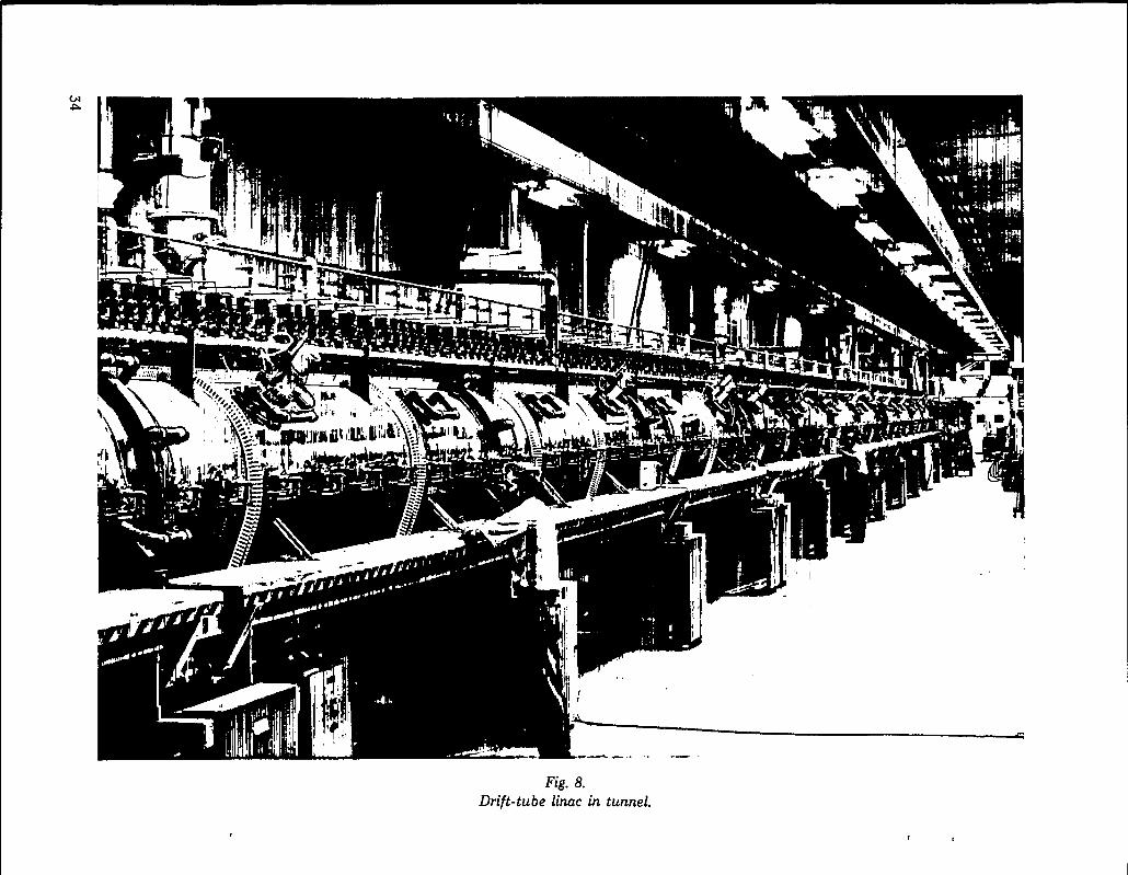
.
34

C. Side-Coupled-Cavity Linac
The main section of the linac is a side-coupled-cavity system developed at LAMPF over the years1963 to 1970 and was the culmination of a longseries of studies and tests on waveguide structures tobe used at 800-MHz frequency. The development atLAMPF that led h the side-coupled cavity startedfrom concepts originally proposed at Harwell whichinvolved tightly coupled resonant systems. TheLAMPF designers chiefly concerned were E. A.Knapp and D. E. Nagle, assisted by a team in-cluding B. Knapp, W. J. Shlaer, and J. M.Potter.
The unique feature of the LAMPF Iinac is the useof an external resonant cavity operating in the 7r/2-mode, which is coupled by slots to each successivepair of resonant cavities between adjacent drifttubes. This coupling system provides efficientcoupling, the necessary phase shifts, and very smallpower losses. By applying small physical distortionsexternally to these cavities in tune-up operations, amechanism of precision fine tuning is also provided.The physical spacing between centers of resonantcavities increases steadily with the increasingvelocity of the particles, so each of the nearly fivethousand individual cavities has a different length.Copper forgings are machined to form the individualhalf-cavities. And a group of such half-cavities withtheir side-coupling units is assembled into a sectionbetween 8 and 10 feet in length and brazed into asolid vacuum-tight structure in an electric-heated,hydrogen-purged furnace. A total of 352 such ac-celerating tank sections was built for the half-mile-Iong Iinac, each with differing dimensions. Themechanical engineering team which designed the
procedures and fabricated the cavity system was ledby H. G. Worstell.
The cavity sections described above are the unitswhich are mounted on piers in the linac tunnel,coupled with flexible vacuum bellows, providedwith vacuum pumps at frequent intervals, and sup-plied with radio-frequency power at 800-MHz fre-quency from the power supplies located in cubiclesalong the tunnel. Various beam-handling devicesare mounted between sections, such as quadruplefocusing magnets, beam sensors, and other controlsystems. A typical section of cells is shown in Fig. 9,and a portion of the installation in the tunnel isshown in Fig. 10.
The virtues of the side-coupled Iin c have beenrecognized by other designers includin{; commercialmanufacturers of linacs for X-ray syst ems. Theprinciple was never patented and so becameavailable to all. Several commercial firms now makeelectron linac X-ray units based on this design, withrated energies between 4 MeV and 1 { MeV.
Another important requirement in the develop-ment of the side-coupled-cavity linac was to providethe radio-frequency power for excitation at800 MHz. D. C. Hagerman was in charge of thisprogram. At the start, the most suitable type ofpower amplifier unit was a source of argument be-tween linac experts; some believed in a coaxitron-type triode power tube; others favored klystrons,although none had yet been built at the required fre-
quency for the peak pulsed power of 1 MW neededfor the linac application. Another possibility was acrossed-field amplifier called the “amplitron.” AtLASL, development contracts were placed withcommercial firms for all three types of amplifiers,and testing programs were set up. T. J. Boyd playeda key role in this engineering development.
Following a long and harrf ving experience withprototype tubes which inclu, led many failures, anacceptable klystron made by Varian was receivedand tested late in 1968, and a decision was made toadapt this amplifier and abandon further develop-ment of the others. This klystron (the VA-862)produces 1‘/4-MW pulses of rf power at 800 MHzwith a time duty factor of up to 12%. Orders wereplaced with Varian for 45 klystrons and with Littonfor 25 of the same type. ?’he number used in theside-coupled-cavity installation is 44; others arecarried as spares.
The control system for phase and amplitude ofthe 800-MHz linac is a unique development by R. A.
Jameson17 of the LAMPF staff. It uses feed-backsignals from pickup loops, which are compared withreference voltages and develop error signals that arefed back to the driving amplifier. One such systemcontrols amplitude; another controls phase. To ob-tain the needed precision, wide-band-width circuitsand absolute standards for amplitude and phasewere developed. Precise tuning is obtained by turn-ing on one unit at a time and tuning to perfectionbefore proceeding to the next unit.
In service the klystron power systems have per-formed well. Tube lifetimes have averaged over
35

/-7”naI
.
_—

—.
.“--7+s
e
-....
-1
/.--4
.s
37

10000 hours, and the rebuilding of used tubes forreuse has proved to be practical.
D. Beam Switchyard
At the end of the linac the beams enter a beamswitchyard in which a variety of focusing anddeflecting magnets and other beam-handling equip-ment is located. The beams are separated, focused,and diverted into their chosen beam runs throughchannels in a thick stack of iron and concrete shield-ing, and into several shielded experimental areas.D.R.F. Cochran led the group responsible fordevelopment of the switchyard and experimentalareas. The experimental facilities are largely con-tained in a cluster of sites around and beyond thebeam switchyard. Deflection magnets providesimultaneous but separated beams of protons andH- ions. A proton beam goes nearly straight aheadinto Line A, and the H- beam is deflected to thenorth by 30° into Line X. Also in the switchyard abeam-splitter magnet can divert a fraction of themain beam to the south into a channel leading tothe Weapons Neutron Research Area. The ex-perimental areas downstream of the switchyard areshown and identified in Fig. 11.
Line X provides H- ion beams for stripper targetsin the channels leading into Lines B and C. Theseproduce proton beams which are further collimated,focused, and directed into experimental areas. Onesuch converted proton beam provides protons forthe Neutron Physics Laboratory and the Nucleon-Nucleon Laboratory in Beam Area B. Another morehighly collimated beam is the input to the High Res-olution Spectrometer in Beam Area C.
The main beam entering Beam Area A goesthrough Target Cells A-1 and A-2, each of whichsupplies scattered or secondary beams for two majorexperimental installations. The reduced-intensitybeam is refocused and then proceeds on into TargetCell A-5 which supplies negative pions to theBiomedical Research Facility, on through an IsotopeProduction Area where major amounts of radio-activity are produced, and finally into Beam StopA-6, beyond which the neutrino facility is located. Acritical problem involved the development ofmagnets which can withstand extremely high radia-tion intensities. Alex Harvey was responsible for
devising magnets with mineral insulation for high-radiation-level environments.
The research facilities described above can beidentified in Fig. 11. More detailed descriptions of -the specialized experimental installations are givenin following sections. A stack of iron and concreteshielding surrounds the beam channel from the end -of the linac, through the switchyard, through BeamArea A including Target Cells A-1 and A-2, throughTarget Cell A-5, and on into the Beam Stop A-6, inan essentially straight line. This entire area is ser-viced from above by a movable crane and shieldedtransport system called “Merrimac,” see Fig. 12.
Merrimac is a large movable carriage mounted onfour B-52 wheel assemblies with pneumatic tireswhich roll on top of the long stack of concrete shield-ing blocks and can transport radioactive itemswithin a box shielded by iron and lead plates to ahot laboratory located above the end of the linactunnel. Above each of the areas to which access isdesired the top concrete and iron blocks can bemoved apart horizontally to open a port beneath theshielded carriage of Merrimac. Then disconnectsystems and hoists can be used to raise equipmentup into the shielded box which is transported to thehot lab. Connect-disconnect systems are providedfor electrical power, cooling water, and other ser-vices, for the magnets and other beam handlingdevices used in the beam line, all controlledremotely. This arrangement provides a flexible han-dling system for a wide variety of items and equip-ment which might become radioactive in service,extending along the entire stretch of beam channelin which beam intensities are highest.
E. Control System
LAMPF was the first major accelerator to adoptfull computer control as an essential element. Theconcept of a control system organized about an on-line digital computer appeared very early in theplanning of LAMPF. A preliminary study offeasibility by R. A. Jameson and H. S. Butler was -
dated 1963. Tom Putnam joined the LAMPF designgroup in early 1964 and accepted responsibility for .the computer control system. This includes pro-grammed control of the accelerator, switchyard, and
38
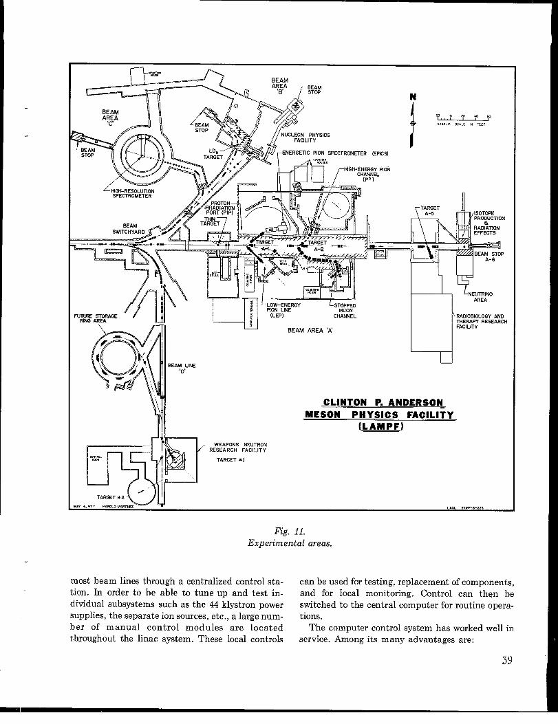
[t.-,,*
WC
BEAM
I 1
NUCLEON PHYSICS
W%YWRO #/j< ‘AR”
Tm-& ~s-cp “ { l-l
BEAM LINE,,D
(LEP) CHANNEL
BEAM AREA X uRAD!QBIOLOGY ANDTHERAPY RESEARCHFACILITY
CLINTON P. ANDERSON,
MESON PHYSICS FACILITY(LAMPF)
NEUTRONFACILITY
*I
IA”4, LASL SKMP-6 -223
Fig. 11.Experimental areas.
most beam lines through a centralized control sta- can be used for testing, replacement of components,tion. In order to be able to tune up and test in- and for local monitoring. Control can then bedividual subsystems such as the 44 klystron power switched to the central computer for routine opera-supplies, the separate ion sources, etc., a large num- tions.ber of manual control modules are located The computer control system has worked well inthroughout the linac system. These local controls service. Among its many advantages are:
39

..-—
.------
.<-
...<
a
-1 .=.....
‘+
1
Ail
iiii!ll
——
.-.
—...—
——
40

1. convenience of controlling thousands of ele-ments from one location,
2. ability to display data about status andperformance, in graphical or tabular form,
3. ability to convert raw data to a more readilyinterpretable form by computer calculationsperformed through predesigned programs,
4. ability of the computer system to searchrapidly and automatically for optimumadjustments of parameters,
5. convenience of automatic storage of variousparameters and records,
6. convenience of local computational facilityfor use as an aid to machine tuning.
Several hundred application programs have beenprepared and are in routine use. Continued studyand use widens understanding of how to expand therange of use of the computer, Computer memoryand other hardware has been expanded con-tinuously and now has a memory of 128000 words.Much of this capability can also be used for applica-tions to research experiments and other activities, ifdesired.
Computerized operations and maintenanceprocedures reduce downtime of the accelerator.Regular reporting of equipment malfunctionsthrough the computer provides statistical andhistorical data which is valuable for analyses ofreliability. A central control system monitors allsignals and shows any deviations from standardsettings.
The cost of the computer system is about 10% ofthe total capital cost of installation. This seems asmall price for the flexibility and capability for ex-pansion available in the computer-based system. Itis unlikely that this complex accelerator could be
tuned and controlled successfully without such acomputer-based system. H. S. Butler, the presentGroup Leader of MP-1, was at the forefront of thecomputer control system for the accelerator.
F. Linac Performance
The time sequence of the accelerator consists of120 pulses/s, each one about 500 ~s long, giving amacro duty cycle of 6Y0. If desired in the future it ispossible to increase pulse length to 1000 gts and theduty cycle to 12%. Each pulse has a microstructureconsisting of a 0.25 ns burst every 5 ns. The energyspread of the beam from the sources is no greaterthan 0.3% (FWHM), and the transverse phase spaceis approximately 7r/3 mrad-cm. When accelerated to800 MeV the energy spread is +0.27., and the beamdimensions can be controlled by focusing magnetsfrom a minimum of 2 mm to a size as large as anychosen target. For example, the optimum beam spotsize at the A-1 target for the EPICS channel is2.0 cm horizontally and 0.2 cm vertically.
It is possible to manipulate beam intensity andpulse sequence at the ion sources from the centralconsole, to match requirements of experiments.Both the H+ and H- beams are acceleratedsimultaneously, the H- micropulses being timed toenter the linac at an instant one-half cycle of theradio-frequency later than the H+ micropulses.When the polarized H- beam is used, it replaces theunpolarized H- beam during the odd half-cycles.The radio-frequency power supplies which providerf power to accelerate the ions are also switched onand off at a duty cycle sufficient to match the ionsources. The parameters of the H+ and H- beamsare given in Table IX.
41
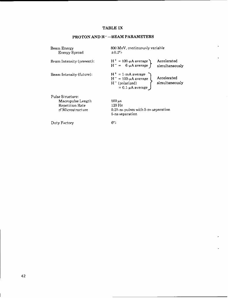
TABLE IX
PROTON AND H-—BEAM PARAMETERS
Beam Energy 800 MeV, continuously variableEnergy Spread +o.2~i
Beam Intensity (present): H + = 1OO-PAaverage
}
AcceleratedH – = 6 -pA average simultaneously
Beam Intensity (future): H + = l-mA average
}
AcceleratedH - = 1OO-PAaverageH - (polarized) simultaneously
= O.I-KA average
Pulse Structure:Macropulse LengthRepetition Raterf Microstructure
Duty Factory
m-l KS120 Hz0.25-ns pulses with 5-ns separation5-ns separation
6(1?,
42

CHAPTER 6
RESEARCH INSTALLATIONS
During the first year of operation of LAMPF forresearch, in 1974, the mode of operation used anegative hydrogen ion beam (10 KA of H- at 5%macroscopic duty factor) which was split in theswitchyard by stripping part of the beam to positiveions for delivery to Area A (Meson Physics Area),with another part diverted for simultaneous deliveryto Area B (Nucleon Physics Laboratory). A diagramof the LAMPF experimental areas is given inFig. 11. Development of the experimental areas wascarried on largely by L. Agnew and R. Macek.
These low-beam intensities were necessitated
largely by the incomplete state of shielding for ex-perimental studies, which in turn was the result oflack of sufficient funds to equip the researchlaboratories in the early years of operation. Low in-tensities were also important to avoid build-up ofradioactive intensity along the linac and in theswitchyard during the early years, while beam con-trols were still under development. Nevertheless,the available intensity was sufficient to initiate aconsiderable number of experiments in Areas A andB and to start experimentation on the biological ap-plications of negative pions. A study of the UsersBulletin covering 1974 shows that 68 experimentswere provided with beam and 4 experiments com-pleted during this phase, which involved a total of16500 beam hours.
During the year 1975 and on into 1976 the facilitywas shut down to allow time for a major main-tenance program which included realignment of thelinac, as well as installation of many new researchexperiments and shielding for the experimentalareas. This rebuilding of the linac allowed an in-crease in the operating intensity level by 10 times,to an average current of 100 PA. Since the facilityresumed operations in September 1975, theoriginally planned mode of operation has been used,in which H+ and H- beams are acceleratedsimultaneously. The main proton beam goesstraight ahead through Area A, while a smaller
beam (-6-~A average) of H- ions is diverted to thenorth for delivery, after stripping to protons, toAreas B and C (see Table IX for beam parameters).
A. Meson Physics Area — Experimental Area A
Most of the precision experiments using mesonsare located in the Meson Physics Area. The mainproton beam from the switchyard goes through thisarea, traversing several targets to generate second-ary pion beams. Two target locations, A-1 and A-2,provide four secondary pion beams, two to the rightand two to the left, which enter shielded areas insidewhich are the experimental instruments. The mesonchannels themselves are permanently assembledarrays of deflecting and focusing magnets, slitsystems, and other devices to produce the type andquality of meson beam desired. The arrangements ofthese four experimental facilities are shown inFig. 13.
1. Imw-Energy Pion Channel (LEP)
This channel is designed to provide beams of #particles from about 20- to 300-MeV energy, whichcovers the resonance region. It is intended to servicea variety of research studies in nuclear structure,nuclear chemistry, elementary particle physics, andbiomedicine. The design features include goodmomentum resolution, a small (achromatic) spotsize for stopped pion experiments and for total ab-sorption counter experiments, and high-intensitybeams at moderate resolution. To facilitate meetinga range of experimental requirements, the final spotsize and divergence are variable over a factor of 20.The general beam parameters are given in Table X.
The LEP channel is formed of four rectangularbending magnets which deflect in the vertical plane;the magnets are oriented to have 60° bends and
43

THIN
TARGET 7SrTr
—COUNTING
/l\ HOUSE
EPICS PIONSPECTROMETER HIGH-ENERGY
\ ik”177rl-,
PION
/
i,
~lq.?$y [COUNTINGHOUSE
, ,
LLow-ENERGyPION LINE
‘STOPPEDMUON CHANNEL
LAMPF EXPERIMENTAL AREA A
Fig. 13.Experimental Area A.
.
44

TABLE X
PARAMETERS OF THE LOW-ENERGY PION BEAM (LEP)
I?nergy Range 20-300 MeV
Flux x+ at 100 MeV:(:\-cm-thick C target) 1.9 x 10⁷ (.Ap/p = +0.05’()
or 1,5 X 10⁹ (Ap/lJ = +?f”()
Resolution Ap/p = +0.05”; (max)
Momentum Bite up to *2!i
Solid Angle 10-20 msr
Bcarn Emittance (+0.13cm X +40mr) X (+1.5cIN X +125 nlr)
13(’am Waist Spot Size Ap/p = O.l(’i: size = +().13 cm, div. = +:10 mrand Divergence Ap/p = I.Or;: size = +0.7 cm, div. = +:)() mr
Jp/p = 5.O!i: size = +:1.4. cm, dilf. = +45 mr
symmetrical beam entrance and exit angles. Two
sets of quadruple focusing magnets are used, oneset at the entrance and one at the exit of the verticaldispersion system; the quadruples have 10-in.bores, 16-in. -long iron cores, with maximum fieldstrengths of 5 kG. A plan view of the LEP channelillustrating the shielding arrangement is shown inFig. 14, and an elevation is shown in Fig. 15. Somerepresentative beam-waist spot sizes and angulardivergences are included in Table X. The fluxesgiven in the table are calculated assuming a 3.0-cm-thick carbon production target and 1-mA protonbeam.
2. Energetic Pion Channel and Spectrometers(EPICS)
EPICS provides a complete system for high-res-olution, two-arm spectrometer experiments. It in-cludes a high-resolution beam channel, a particleseparator for reducing backgrounds, a scatteringchamber at the focal spot of the beam channel, aspectrometer pivoted about this target location, anddetection systems at the outputs of the spec-trometers. Plans include adding a second spec-trometer on the same pivot. See layout of the chan-nel in Fig. 16 and details of the first spectrometer in
Fig. 17. It is intended for nuclear structure experi-ments using either positive or negative pions for thebombarding particles, and is equipped for rapidchange of targets, automatic scanning through spec-trometer angles, and a fast data-acquisition system.Design and construction of EPICS and other largespectrometer systems was done by A. Thiessen, J.Spencer, and K. Tanaka.
The pion production target in the main beam isplanned to be a block of graphite of 3-cm thicknessalthough it can be of any chosen thickness andmaterial. The pion channel accepts particles scat-tered in the horizontal plane at 35° productionangle. The beam-analysis channel has four bendingmagnets which disperse and recombine the beam inthe vertical plane, with slit systems at beam cross-over points and an electrostatic separator toeliminate unwanted protons and other particles.Performance characteristics of the channel areshown in Table XI.
The initial low-momentum spectrometer arm il-lustrated in Fig. 17 has a momentum range from 100to 680 MeV/c. This permits a variety of experimentssuch as elastic and inelastic pion scattering, and thestudy of certain two-particle interactions which canbe performed with one spectrometer. Ultimately asecond, high-momentum spectrometer(1000 MeV/c) will be installed to increase the range
45

—
1-&
/./”
A-—
—-----d
“d
tI
=~
..~.-,-. ......,~.-—
r ,--—-.--—
.
-EE

.
(:“
I
II...
id”,,..
II“{
II~.
47

I
——
●�
-41--I
Tk
m
l:,
‘N0.
—I
5
HIH
.,a
~lY
ll)i\
-41#-,,,
,-+
----,/
——
●�
/l/
==ii!-x
I
L
.—
..
48
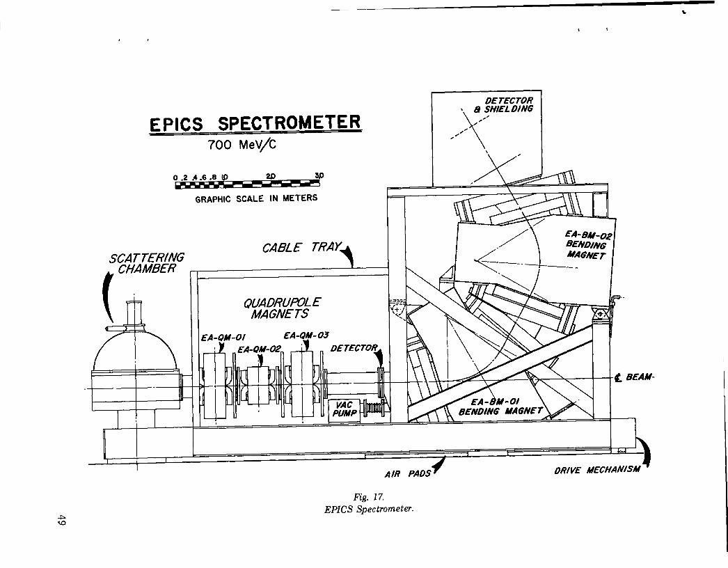
..
IIII
I
1I
I1
r—
49

TABLE XI
EPICS PION CHANNEL AND
Channel
Range 50-300 MeVFlux at 1 mA 4 x lo~7r+/sResolution 2.4 X 10⁻⁴Solid Angle: Ml 2.5 msrAplp +1 c;,
and type of experiment-s. This will allow study of thereactions: (r, r’), (m,p), (r, m’p) and (m,pp) over thefull energy range, and of (r,d) and (x,T) reactions atlower energies.
andloss
SPECTROMETER
Initial Spectrometer
1OO-G8OMIsVIC0.5 7r+/min/#b/sr3X1 O-410 msr*5C(.
a carbon moderator having a 35-MeV energyis used before the stopping target, then the
number of muons stopped in a 100-mg/cm* target is4 X 10’ ~/s with 1-mA protons. The total muon fluxon the target would be 13 X 10s I.L/sin this case.
3. Stopped Muon Channel (SMC)4. Pion and Particle Physics Channel (P’)
This channel provides beams of Iow-energy muonsuseful in experiments in which they can be stoppedin targeta or detectors. One example is the use of p+beams for experiments on muonium; another is P-beams for muonic X-ray studies. The channel has apion-collection portion, a pion-decay section, andan analysis system in which muons of specificmomenta can be selected for experimental use. Aswitching magnet at the output allows the muons tobe directed into one or the other of two experimentalcaves. See Fig. 13.
The primary target in the main beam is a carbontarget 6 cm thick. The pion-collection channelviews the target at 65° in the horizontal plane, witha pair of large aperture quadruple magnets to
collect a wide angular spread of low-energy pions.Bending magnets of wide aperture and a longsequence of quadruples provide distance for someof the pions tQ decay, and forms a large-diametermuon beam. The muons selected are those whichdecay in the backward mode, which are the slowest.The analyzing system has a 70° deflection magnet,additional focusing quadruples and a final switch-ing magnet to produce either of two beams. Theperformance characteristics of the channel are givenin Table XII.
The stopped muon flux detected depends in parton the size of detector used. For example, if themuon momentum band selected is at 100 MeV/c,
This channel provides a flexible, general purposepion line capable of transmitting the highest energypions which LAMPF can produce. It is intended forboth nuclear reaction and elementary particle ex-periments. The channel is basically a two-bendchannel augmented with a third bend which willswitch the beam between two spatially separatedexperimental areas (see Fig. 18). Both beams can bemade achromatic. To provide high intensity, theproduction angle is forward, at 20°, and the collect-ing quadruple is placed as close as possible to thebeam line. For flexibility in rearrangements thechannel is built with magnets of conventional design(i.e., rectangular dipoles and standard 8-in. -aperture quadruples). A brief list of typicalperformance characteristics is given in Table XIII.
TABLE XII
STOPPED MUON CHANNEL
Range 0-165 MeVFlux (Positive Muons) 6 X 10⁷p+/s (at 60 MeV)Stopping Flux 1 x 10’ p-/g/s
.
(Negative Muons)Purity 1% T: <l%ePolarization 0.8Spot Size 5cm X10cm
50
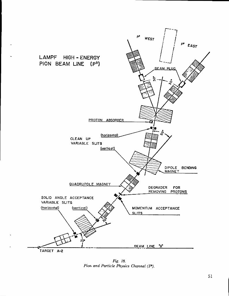
. LAMPF HIGH - ENERGYPION BEAM LINE (P3)
.
CLEAN UP
VARIABLE SLIT
\/f=
%.
DIPOLE BENDING\“ MAGNET
6QUADRUPLE MAGNETDEGRADER FORREMOVING PROTONS
SOLID ANGLE ACCEPTANCE
VARIABLE SLITS
MOMENTUM ACCEPTANCE
SLITS
‘YAM LINE ‘A”----— r --- Uc
TARGET A-2
Fig. 18.Pionand Particle Physics Channel(p).
51

B
TABLE XIII
HIGH-ENERGY PION CHANNEL (Ps)
Range 100-600 MeVFlux 3 X 10’ m+/s (at 400 MeV)Resolution 2.5 X 10⁻³Ap/p ~r;Emittance 30 mr-cm
Neutron beams can be formed by collimation at0°, 7°, 14°, 20°, 27°, and 37° from the proton beamdirect ion at the LiD, target. These beams providelower energy neutrons; also, the proton beam energy -can be varied in the linac between 300 and 800 MeV.Neutron beams at the larger collimation angles arepartially polarized; those at 27° are calculated to -have a polarization P = 0.35.
‘. Nucleon Physics Laboratory — Experimental 2. External Proton Beam (EPB)
Area B
The beam of H- ions diverted into Beam Line Xat the switchyard traverses first a partial stripperfoil which strips the electrons from some of the H-ions to form an input proton beam for Line C. Theremaining H- beam continues and traverses anotherstripper foil to produce a proton beam in Line Bwhich supplies the Nucleon Physics Laboratory(NPL). See Fig. 19. The objectives are to providehigh-quality beams of protons of variable energy,and also neutrons of good energy resolution, to beused for nucleon-nucleon research.
1. Neutron Beams
A major portion of the H- beam which is strippedof electrons provides .a proton beam which is fo-cused and directed against a liquid deutenum
(LD,) target to produce neutrons. The proton beampasses through a number of bending and quadruplefocusing magnets which control spot size on thetarget to a size of 1.5 cm by 2.0 cm or smaller. Theemerging proton beam is deflected horizontally byother magnets and refocused to provide beam spotsat two nuclear chemistry stations downstream of thelast bending magnet.
The neutrons observed from a 10-cm-thick LD,target, with a I-pA-average proton beam at800 MeV, in the forward direction (00), and in a 4-cm-diam aperture located 6 m from the target, were
measured to have an intensity of 5 X 10S ~s. Theenergy of the neutrons was 795 MeV and the res-olution was *13 MeV (FWHM). A background oflower energy neutrons associated with pion produc-tion results in a low-energy tail on the neutron spec-trum. The neutron spot size is variable but istypically 10 cmz at 6 m from the LDZ target.
That portion of the H- which is not stripped andused for neutron production goes straight on downLine EPB where it enters a shielded cave in theNucleon Physics Laboratory and can be used eitheras an H- beam or stripped to a proton beam.Quadruple focusing magnets are used to adjustspot size at various locations for experimentaltargets. Usually this external proton beam providesa pencil beam of about 3-mm diam and with anenergy resolution of *3.5 MeV at 8CXIMeV. The sizeof the beam is predominantly determined by thesize of the hole in the stripper used to form the EPBH- beam. Intensities are limited at present but canbe increased if required with further shielding of thecave and the beam stop.
With use of the polarized H- ion source in thefuture, the EPB will provide about 15 nA ofpolarized protons with P = 0.9. First delivery of apolarized beam was made in April 1977.
C. High-Resolution Spectrometer (HRS)
Experimental Area C houses the high-resolving-power spectrometer facility and its associated beamline, as shown in Fig. 20. The optics of Beam Line Cand of the I-IRS have been designed to give amomentum resolution on the order of 2.4 X 10⁻⁶, anangular resolution of *10-s rad for a moment urn ac-
ceptance of 2%, and a solid angle accept ante of3.6 msr. As a result, the spectrometer should be able -to resolve nuclear levels separated by as little as30 keV at 800 MeV when operating at full design -resolution. Using a target thickness of 10 mg/cm*,which is consistent with such a resolution, and aproton current of 10 PA, a counting rate on the or-der of l/s/(nb/sr) should be possible.
52

..
ZE
Q“<
(3id
l––mm
Qi’
u<
53

7’N
LC-QM-11
LC-QM-10
LC-QM-09
LC-QM-OB
LC-QM-07
LC-QM-06
LC-QM-05
LC-QM-04
LC-OM-03
LC-BM-05
k LB. BM.01 = LB-ST-01.,— -.” .. . . . .
.
.
.
Fig. 20.Experimental Area C.
54

.
.
The research capability covers a broad range ofpossibilities for both particle physics and nuclear
structure research. Several possibilities are: a) thestudy of nuclear reaction mechanisms over a broadrange of incident energies; b) high-resolutionnuclear spectroscopy involving proton pick-up reac-tions; c) pion or kaon production reactions leadingto discrete final nuclear levels; d) proton-producedreactions which are complementary to those ob-tained using pions which are of particular interest atLAMPF.
The HRS spectrometer consists of a large aper-ture quadruple lens followed by two 75° bendingmagnets, known as the “QDD” system. The bend-ing magnets are in the vertical plane, arranged torotate as a unit around a pivot at the location of thespectrometer target. The detector and the time-of-flight electronic identification system are located onthe top of the spectrometer carriage above the pivot.The entire spectrometer rotates about a vertical axisat the pivot and is enclosed within a hemisphericaldome of 14-m radius, which is covered with earth fillfor shielding. A sectional sketch of the HRS facilityis shown in Fig. 21. Specifications of Beam Line Cand the HRS spectrometer are given in Table XIV.
D. Thin Target Area
This facility is located in Beam Line A just up-stream of the Area A shielding wall. It is designed toallow on-line studies of nuclear reactions induced by800-MeV protons. The mechanisms of high-energynuclear reactions, and the de-excitation of highlyexcited nuclei, will be studied by utilizing dE/dxand time-of-flight techniques to measure the energyspectra, angular distributions, and total yields of alarge number of both stable and radioactive nuclearreaction products such as ‘iC, ‘C, and ‘8C.
A scattering chamber in the main beam linevacuum pipe contains a remote target retractor andpositioning mechanism that can hold four targets.The arrangements are shown in Figs. 22 and 23.These will be thin targets of less than 10-4 radiationlengths thick. The scattering chamber has outletpipes emerging at seven angles which lead to detec-tion instruments behind a shielding wall. The anglesare: 20°, 45°, 60°, 90°, 120°, 135°, and 160°. Drift-tube detectors have been installed in several of the
TABLE XIV
SPECIFICATIONS OF LINE C AND HRS
Incident Proton Beam
1. Energy variable in steps from 100-800 MeV.2. 0.1 r cm mr phase space for 96% of the beam
and 0.3 m cm mr phase space for 99?40of thebeam.
3. Momentum spread of Ap/p = 0.26%.4. Maximum average proton current of 10 pA.5. 50-to 100-nA average polarized proton current.6. Maximum dispersion at full phase space =
40 cm/%.
(JDD Spectrometer
1.2.
3.4.
5.
6.
7.
8.9.
Central radius of curvature = 3.5 m.Solid angle = 3.6 msr.Maximum induction = 19 kG.Momentum acceptance = 4%.Momentum resolution = +1.5 X 10⁻⁵.Angular resolution = AO.8 mr.Range of scattering angles = 10-168° and 0-10°with reduced intensity.Flight path x 19.5 m.Dispersion <AX/Ap> = 18.25 en-d%.
outlet pipes, with silicon detectors and suitable elec-tronic recording circuits.
The limitation of this area is that access isthrough the switchyard and is possible only whenthe accelerator is turned off.
E. Nuclear Chemistry Facilities
The nuclear chemistry program emphasizes suchreactions as spallation, fission, and fragmentation.These phenomena are observed primarily in thehigh-energy proton beam or from high-energyneutrons. Studies include the decay properties ofnuclides well away from the @-stability line pro-duced in proton and neutron reactions. However,there is also interest in reactions involving chargeexchange between pions and muons and complexnuclei, so it is also important to provide exposures topion and muon beams.
There are four stations for exposure of chemical
samples to beams, two in proton beams, one in the
5s

gu,
Fig.
21.H
igh-R
esolution
Spectrom
eter,elevation
(HR
S).
56

—
..
—,,’.-.
.;,,.:,,
b.:;,
‘.m
“ .’...;
.,w
-.’:
~;,.<
....;...,..,.......,,
—N
.
:1:1:-m&zE
Fig.
22.
Th
intarget
area,plan
view.
57
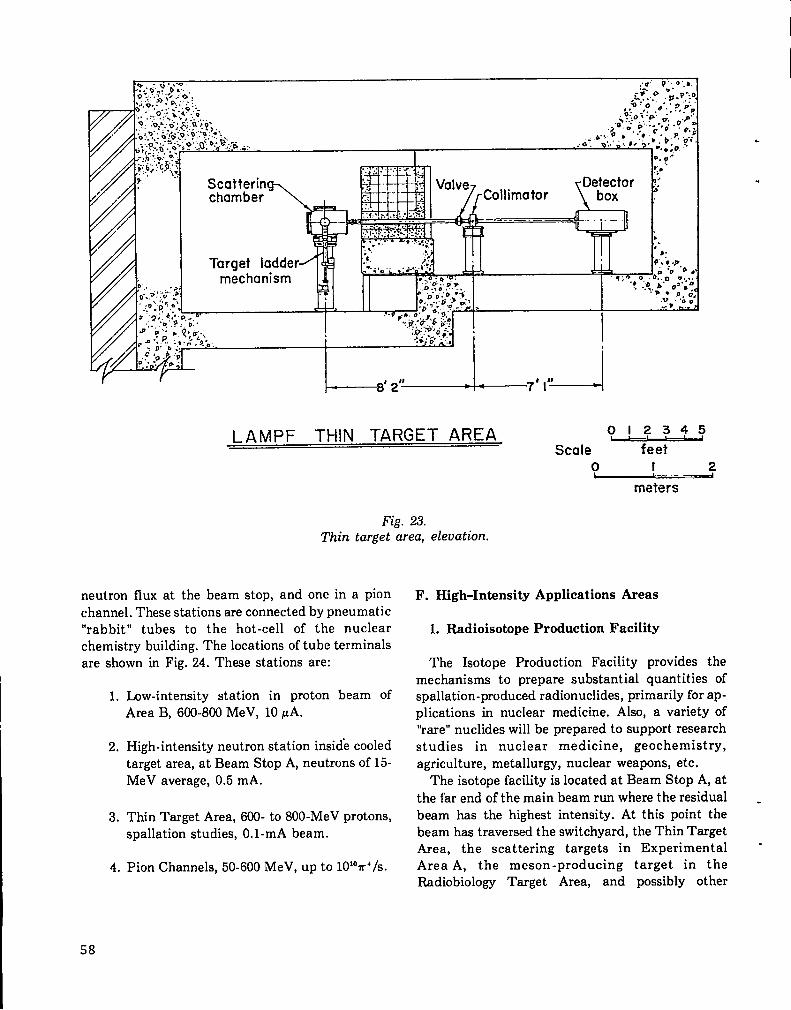
LAMPF THIN TARGET AREA OJ z_3 f !j
Scale feeto I 2—
meters
Fig. 23.Thin target area, elevation,
neutron flux at the beam stop, and one in a pionchannel. These stations are connected by pneumatic“rabbit” tubes to the hot-cell of the nuclearchemistry building. The locations of tube terminalsare shown in Fig. 24. These stations are:
1. Low-intensity station in proton beam ofArea B, 600-800 MeV, 10 PA.
2. High-intensity neutron station inside cooledtarget area, at Beam Stop A, neutrons of 15-MeV average, 0.5 mA.
3, Thin Target Area, 600- to 800-MeV protons,spallation studies, O.1-mA beam.
4. Pion Channels, 50-600 MeV, up to 10iOm+/s.
.
.
F. High-Intensity Applications Areas
1. Radioisotope Production Facility
The Isotope Production Facility provides themechanisms to prepare substantial quantities ofspallation-produced radionuclides, primarily for ap-plications in nuclear medicine. Also, a variety of“rare” nuclides will be prepared to support researchstudies in nuclear medicine, geochemistry,agriculture, metallurgy, nuclear weapons, etc.
The isotope facility is located at Beam Stop A, at
the far end of the main beam run where the residual .beam has the highest intensity. At this point thebeam has traversed the switchyard, the Thin TargetArea, the scattering targets in Experimental -Area A, the meson-producing target in theRadiobiology Target Area, and possibly other
58

..
2*(n<Idm
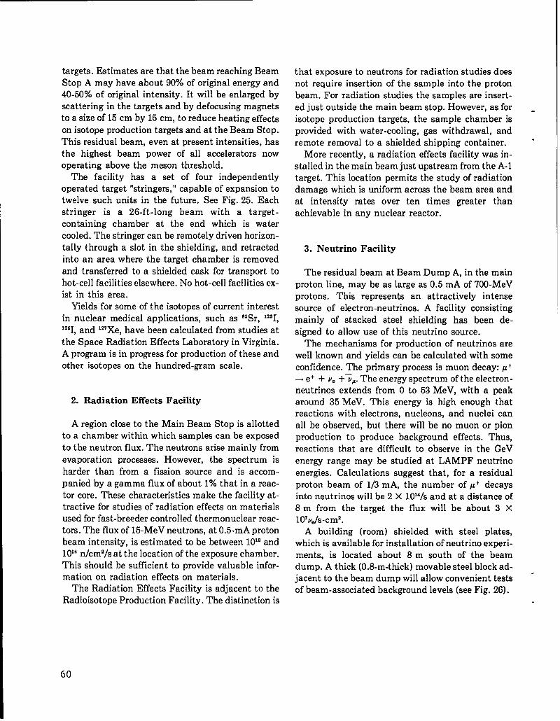
targets. Estimates are that the beam reaching BeamStop A may have about 90% of original energy and40-50% of original intensity. It will be enlarged byscattering in the targets and by defocusing magnetsto a size of 15 cm by 15 cm, to reduce heating effectson isotope production targets and at the Beam Stop.This residual beam, even at present intensities, hasthe highest beam power of all accelerators nowoperating above the meson threshold.
The facility has a set of four independentlyoperated target “stringe~, ” capable of expansion totwelve such units in the future. See Fig. 25. Eachstringer is a 26-ft-long beam with a target-containing chamber at the end which is watercooled. The stringer can be remotely driven horizon-tally through a slot in the shielding, and retractedinto an area where the target chamber is removedand transferred to a shielded cask for transport tohot-cell facilities elsewhere. No hot-cell facilities ex-ist in this area.
Yields for some of the isotopes of current interestin nuclear medical applications, such as a2Sr, 12S1,1261and 127Xe,have been calculated from studies atthe’ Space Radiation Effects Laboratory in Virginia.A program is in progress for production of these andother isotopes on the hundred-gram scale.
2. Radiation Effects Facility
A region close to the Main Beam Stop is allottedto a chamber within which samples can be exposedto the neutron flux. The neutrons arise mainly fromevaporation processes. However, the spectrum isharder than from a fission source and is accom-panied by a gamma flux of about 1% that in a reac-tor core. These characteristics make the facility at-tractive for studies of radiation effects on materialsused for fast-breeder controlled thermonuclear reac-tors. The flux of 15-MeV neutrons, at 0.5-mA protonbeam intensity, is estimated to be between 10’8 and10’4 n/cm2/s at the location of the exposure chamber.This should be sufficient to provide valuable infor-mation on radiation effects on materials.
The Radiation Effects Facility is adjacent to theRadioisotope Production Facility. The distinction is
that exposure to neutrons for radiation studies doesnot require insertion of the sample into the protonbeam. For radiation studies the samples are insert-ed just outside the main beam stop. However, as forisotope production targets, the sample chamber isprovided with water-cooling, gas withdrawal, andremote removal to a shielded shipping container.
More recently, a radiation effects facility was in-stalled in the main beam just upstream from the A-1target. This location permits the study of radiationdamage which is uniform across the beam area andat intensity rates over ten times greater thanachievable in any nuclear reactor.
.
.!
3. Neutrino Facility
The residual beam at Beam Dump A, in the mainproton line, may be as large as 0.5 mA of 700-MeVprotons. This represents an attractively intensesource of electron-neutrinos. A facility consistingmainly of stacked steel shielding has been de-signed to allow use of this neutrino source.
The mechanisms for production of neutrinos arewell known and yields can be calculated with someconfidence. The primary process is muon decay: p ++ e+ + v. +;P. The energy spectrum of the electron-neutrinos extends from O to -53MeV, with a peakaround 35 MeV. This energy is high enough thatreactions with electrons, nucleons, and nuclei canall be observed, but there will be no muon or pionproduction to produce background effects. Thus,reactions that are difficult to observe in the GeVenergy range may be studied at LAMPF neutrinoenergies. Calculations suggest that, for a residualproton beam of 1/3 mA, the number of p+ decaysinto neutrinos will be 2 X 10i4/s and at a distance of8 m from the ta~get the flux will be about 3 X10⁷v~s-cm2.
A building (room) shielded with steel plates,which is available for installation of neutrino experi-ments, is located about 8 m south of the beamdump. A thick (0.8-m-thick) movable steel block ad-jacent to the beam dump will allow convenient tests -of beam-associated background levels (see Fig. 26).
60
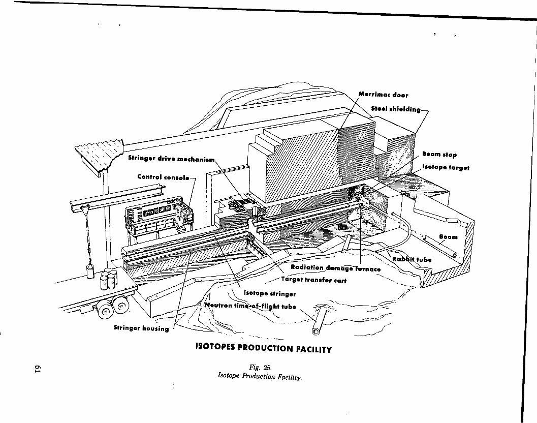
..
/
—

BEAM ST OP N
,- 0“
(5.486m)
/
it
NEUTRINO DETECTORAREA
3’- 3“
(.99m)
Fig. 26.Neutrino Facility, top view.

.
.
CHAPTER 7
PRACTICAL APPLICATIONS
LAMPF is a multiple-use facility which allowsmany experiments to be conducted simultaneously,with minimal interference between them, and whichhas surplus beam intensity available to be used for avariety of practical applications at the same time.Recognizing this fact, LAMPF organized the firstpractical applications group at a major acceleratorfacility, headed by E. A. Knapp and J. N. Brad-bury. During the first years of operation several ofthese applications have been exploited and manymore are planned for the future. Perhaps the mostexciting development is the application of negativepions to the management of cancer. A joint effort toevaluate the possibilities of cancer treatment is un-der way at present, funded by the National CancerInstitute and staffed from the University of NewMexico Medical School and LASL. Other applica-tions apply to medical instrumentation, such ashighly efficient X-ray systems using electron Iinacsbased on the LAMPF linac design, and an elec-trosurgical tool developed by members of theLAMPF staff. Still other applications involve radio-isotope production and use, and the utilization ofother secondary radiations such as muons, neutrons,and neutrinos.
A. Biomedical Facility
Nuclear physicists have known for years of thespecial property of negative mesons, on slowingdown in matter, of being attracted to and absorbedby atomic nuclei with the release of the surplusmass energy of the pion as a “star” of nuclear frag-ments. The ionizing particles in such stars(primarily protons and alpha particles) haveenergies of 5 to 20 MeV and ranges in light mattersuch as tissue of only a few microns. This concentra-tion of ionization at the end of the range of a pionbeam is many times greater than the ionizationpeak at the end of range of protons or light-charged
particles (the Bragg peak). See Fig. 27. This differsfrom positive pions which are not attracted bypositively charged nuclei and decay into muons.Such a concentration of ionization was known tomedical therapists to be potentially useful in thetreatment of deep-seated tumors. Fowler andPerkins18 calculated the characteristics of an ac-celerator capable of pion therapy as early as 1961.However, until LAMPF was conceived none of theexisting meson-producing accelerators couldproduce sufficient intensities to make an applica-tion possible.
In early 1962, Rosen calculated the yield of pionsexpected from LAMPF and convinced himself thatradiation doses of 50 to 100 rad/min over 1000 cmgcould be obtained. This intensity is therapeuticallyvaluable, and it gave him confidence to proceedwith plans to exploit this property of the pionbeams. Note, however, that the biomedical utiliza-tion of LAMPF was never claimed to be a majorreason for building the facility.
Rosen spent several years convincing the medicalcommunity that pions might provide a worthwhilemethod of treatment of cancer. One of his first stepswas publication of a paperle in December 1968,presenting his calculations of radiation dosage.Some of his early supporters in the medical profes-sion were Dr. Max Boone of the University ofWisconsin, Dr. Robert Stone of the University ofOregon Medical School, and Dr. Henry S. Kaplan ofStanford University. The Atomic Energy Commis-sion was informed of the possibilities and support-ed further efforts to speed up the planning. Rosenalso described the opportunity to the Joint Commit-tee on Atomic Energy at several Hearings inFebruary 1967, April 1969, and March 1970. Dr.John R. Totter, Director, Division of Biology andMedicine of the AEC, welcomed the early planningand requested proposals to stimulate the develop-ment. A formal proposal was prepared by Dr.
63
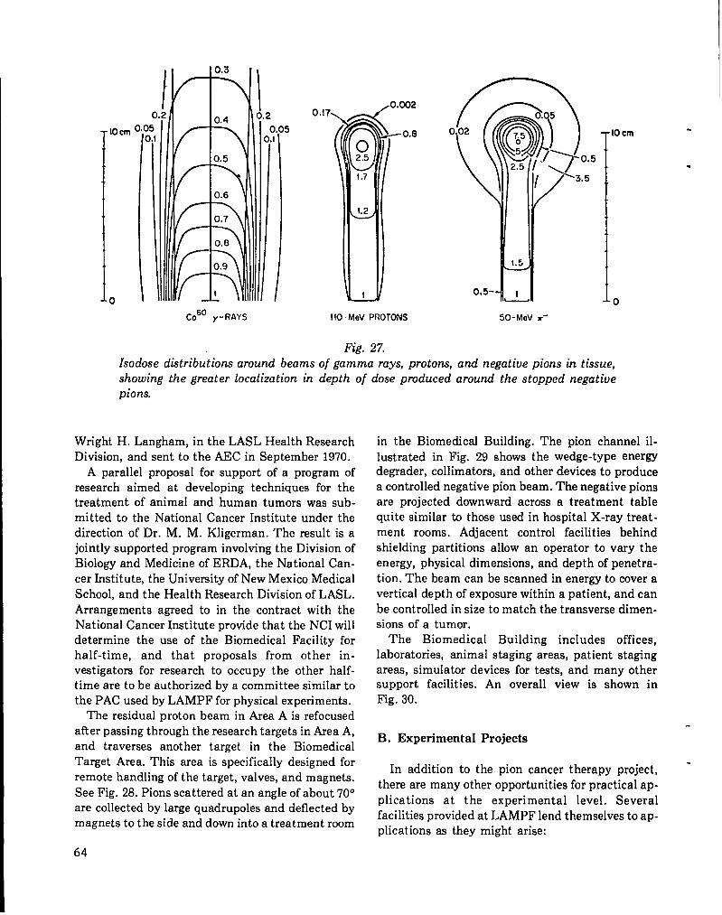
o
IOcm ‘
o
Co’” y-RAYS
5(
0.02
(
(
(
o,5-
ffO. MeV PROTONS 50-MoV r-
Fig. 27.
0 cm.
.
0
Isodose dktributwns around beams of gamma rays, protons, and negative pions in tissue,showing the greater localization in depth ofpions.
dose produced around the stopped negative
Wright H. Langham, in the LASL Health ResearchDivision, and sent to the AEC in September 1970.
A parallel proposal for support of a program ofresearch aimed at developing techniques for thetreatment of animal and human tumors was sub-mitted to the National Cancer Institute under thedirection of Dr. M, M. Kligerman. The result is ajointly supported program involving the Division ofBiology and Medicine of ERDA, the National Can-cer Institute, the University of New Mexico MedicalSchool, and the Health Research Division of LASL.Arrangements agreed to in the contract with theNational Cancer Institute provide that the NCI willdetermine the use of the Biomedical Facility forhalf-time, and that proposals from other in-vestigator for research to occupy the other half-time are to be authorized by a committee similar tothe PAC used by LAMPF for physical experiments.
The residual proton beam in Area A is refocusedafter passing through the research targets in Area A,and traverses another target in the BiomedicalTarget Area. This area is specifically designed forremote handling of the target, valves, and magnets.
See Fig. 28. Pions scattered at an angle of about 70°are collected by large quadruples and deflected bymagnets to the side and down into a treatment room
64
in the Biomedical Building. The pion channel il-
lustrated in Fig. 29 shows the wedge-type energydegrader, collimators, and other devices to producea controlled negative pion beam. The negative pionsare projected downward across a treatment tablequite similar to those used in hospital X-ray treat-ment rooms. Adjacent control facilities behindshielding partitions allow an operator to vary theenergy, physical dimensions, and depth of penetra-tion. The beam can be scanned in energy to cover avertical depth of exposure within a patient, and canbe controlled in size to match the transverse dimen-sions of a tumor.
The Biomedical Building includes offices,laboratories, animal staging areas, patient stagingareas, simulator devices for tests, and many othersupport facilities. An overall view is shown inFig. 30.
B. Experimental Projects
In addition to the pion cancer therapy project, -there are many other opportunities for practical ap-plications at the experimental level. Severalfacilities provided at LAMPF lend themselves to ap-plications as they might arise:

.
.
Fig. 28.Biomedical Target Area and general arrangement.
65

T
Q-T-B-s-D-w-v-c-
SHIELDING /
K
R~
~QQUADRUPLE MAGNET
I
PION PRODUCTION TARGET I IBENDING MAGNET 1 IQ
1BEAM STOPMOMENTUM DISPERSION PLANEWEDGE ENERGY DEGRADER
~,~Q
VARIABLE THICKNESS DEGRADER
+
COLLIMATORSM-BEAM MONITOR
,::,zv:F?:c&’’’’,’LANE
1 METER
.
.
FALSE FLOOR
THE LOS ALAMOS MESON PHYSICS FACILITY
BIOMEDICAL PION CHAfvNEL
STUBOUT FLOOR
Fig. 29.Biomedical Pion Channel,
66

.t-
1
\
t-”

1. Radioisotope Production Facility
The surplus proton beam intensity in Area A atthe Beam Stop is many times larger than the totalfrom all accelerators now operating at energiesabove the meson threshold. This installation ob-viously will become a major source of radioisotopesto be used in other scientific fields. Of particular in-terest are the radionuclides used for diagnosis andtreatment in medicine. In the last chapter thearrangements provided for exposure of samples tothe beam in remote-handled, cooled target cham-bers were described.
2. Radiation Damage Studies
Neutrons from the main beam stop have anenergy spectrum and sufficient intensity to be usefulfor studies on the radiation-damage effects onmaterials used for reactor cores, especially for fast-breeder and controlled thermonuclear reactors.Recently, use of the direct proton beam forradiation-damage studies has been proposed. Thistechnique shows promise in giving a quick test forradiation-damage properties of materials used inreactor cores, etc.
3. Neutron Beams
The neutrons of known and controllable energy,both at 90° and in the forward direction at targets inthe Nucleon Physics beam in Area B, might wellhave a variety of applications in other fields ofphysics, such as the physics of the solid state.
4. Muonic X Rays for Analysis
Muonic X rays have proven to be a very usefulelemental analysis tool. For high-Z elements theyalso have an isotopic discrimination capability. Theimportant feature of this type of analysis is that it isnondestructive, similar to neutron activation or thetechnique of X-ray fluorescence. Muonic X raysprovide a technique which allows development of anaccountability system based on direct physicalmeasurement which is nondestructive and requiressamples of only a few grams of fissionable material.
The physical principle is as follows: Low-energy,negative pions produced in a scattering target (car-bon or copper) are captured in a beam transportsystem and allowed to decay in flight (half-life ●
about 20 ns) into negative muons. The muon comesto rest in the surrounding matter of the sample andis captured by a nearby nucleus of the sample into a +loosely bound atom consisting of that nucleus andthe muon. The p- has much the same properties asan electron except that its mass is 200 times that ofthe electron. The atom which is formed is similar toa hydrogen atom, with one orbiting muon and othermuonic orbits empty. The single muon cascadesdown to the more tightly bound muonic orbits withthe de-excitation energy being given off as muonicX rays. The muonic X-ray energies are charac-teristic of the element and precisely calculable. So,the measured spectrum of muonic X rays identifiesthe element of the sample. In the case of heavy ele-ments such as fissionable ones, the X ray will evendistinguish between isotopes. After the muonreaches the lowest orbit it decays (T = 2.2 ps) or in-teracts with the npcleus.
Muonic X rays are quite energetic, since themuon is so heavy. For example, in 206Pbthe K X-raytransitions for the electron system are about 75-keVenergy; the same transition energy for a muon withthe same nucleus is 200 times greater or about15 MeV. Since muonic X rays are so energetic theyare also penetrating, allowing the analysis of bulkysamples. Furthermore, the muons themselves arepenetrating; a 200-MeV muon beam has a range of12 cm in Pb, for example. So the muons canpenetrate large or dense samples.
The X rays are observed in a high-resolution ger-manium detector located at the side of the samplebeing irradiated by the muons. A coincidence-anticoincidence system is used with counters whichidentify the muon which attaches to the targetnucleus with the X ray which results.
Preliminary data supports the contention thatthis technique is feasible, and a program preparingfor the analysis of real samples is being developed.The electronic sensitivity of the detectors and the -calculational capabilities are being refined to im-prove the discrimination for isotopes.
Another possible application of muonic X rays isfor diagnostic applications in medicine.
68
C. Technology Transfer
1. Side-Coupled-Cavity Linacs for X-RaySystems
The concept of the side-coupled waveguide struc-ture for linear accelerators has been widely accept-ed and used by commercial producers of medicaland other X-ray systems. This structure results inmuch higher electric field gradients than earlierlinac structures, such that higher final energies canbe obtained in relatively short structures. This inturn allows the linac to be mounted on gimbalswhen used as the electron beam source for an X-raysystem, a decided advantage for clinical use inhospitals. Six to eight producers of X-ray systemshave adopted this technique and have developedand marketed X-ray units based on the side-coupledwaveguide structure. Several hundred units are nowin service, in the energy range of 4- to 18-MeV X-rays.
2. Electro-Surgical Tool
A team of LASL scientists, including J. D. Dossfrom LAMPF, has developed a special surgical toolwhich cuts and cauterizes blood vessels instantly,using electrical heating for the cautery. Develop-ment is proceeding with the collaboration of sur-geons at the University of New Mexico MedicalSchool and the Los Alamos Medical Center.
3. Thermal Treatment of Tumors
The use of radio-frequency waves to generate hightemperatures in superficial tumors is being exploredby a team of LAMPF scientists (J. D. Doss) andphysicians from the local medical schools. One earlysuccess is the apparent cure of a nonmalignanttumor on the trunk of an elephant at the Albuquer-que Zoo.
-
4. Tumor Diagnostic Studies
Electronic skills of the LAMPF staff are also be-ing applied to the diagnosis of breast cancer. A tem-perature measuring and recording instrument
developed at LAMPF is presently under test byphysicians at the University of Arizona MedicalSchool, Tucson, Arizona.
D. Weapons Pulsed Neutron Facility
An application more appropriate to the mission-oriented aspects of LASL than to basic scientificresearch is the use of high-intensity short pulses ofneutrons which can be obtained from the linacbeam. Much of this work will be classified forsecurity reasons and it will be performed in a sep-arate guarded building with no connection toLAMPF except the underground tunnel throughwhich the beam enters the building. See location ofBeam Line D in Fig. 10. A fraction of the mainbeam will be diverted to the south in the switch-yard and will traverse a tunnel into the speciallaboratory. Future plans call for collecting theproton beam in a storage ring in a single turn to form
a short pulse which will produce a pulse of neutronson striking a target. The expectation is a broad spec-trum of neutron energies with a peak at 1 to 2 MeV,in pulses at a repetition rate of 120 pulses/s and withintensities of 10IZn/s in each pulse.
Some of the applications of this pulsed neutronbeam are:
1.
2.
3.
4.
5.
6.
Measurement of cross sections needed forweapons design, vulnerability, calculationsand evaluation of diagnostics.
Tests of weapon design codes for simplesystems.
Simulation experiments on complex weaponsystems, a) as a test of vulnerability and, b)to provide input to weapons codes.
Measurement of shock-wave andhydrodynamic data (as a supplement toPhermex).
Neutron and proton radiography (as a non-destructive test of weapons components andsystems.
Detector calibration (for underground testand other uses).
69

.

REFERENCES 11. The Charter is presented in Ref. 3 as Appen-dix C.
. 1. ‘R..devance of Particle Accelerators to National
Goals,’’ Louis Rosen, Science 173, 490 (1971).
2. ‘The Clinton P. Anderson Meson PhysicsFacility (LAMPF), ” Louis Rosen, Proc. Nat.Acad. Sci., 70, 603 (1973).
3. “Origins and History of the Los Alamos MesonPhysics Facility, ” M. Stanley Livingston, LosAlamos Scientific Laboratory report LA-5000(June 1972).
4. Schedule 44, Construction Project Data Sheet,“LOS Alamos Meson Physics Facility, ” August1963.
5. “Meson Factories, ” Louis Rosen, Physics Today,19 (December 1968).
6. “High Intensity Proton Accelerators, ” Yale in-ternal report Y-12 (October 1964).
7. “Proposal for MC2 Isochronous Cyclotron, ” OakRidge National Laboratory report ORNL-3540(November 1, 1963).
8. “Proposal to the U.S. AEC for . .. a Cyclotron forthe Production of Large Fluxes of Mesons, ” J. R.Richardson, K. R. McKenzie, B. T. Wright, D.H. Stork, and R. P. Haddock, July 1960.
9. “Bethe Panel Report on Meson Factories, ” H. A.Bethe, Chairman, Office of Science andTechnology Report (March 1964).
10. Schedule 44, Construction Project Data SheetII, “Los Alamos Meson Physics Facility, ” Oc-tober 30, 1964.
12. “LAMPF Users Handbook, ” Los Alamos Scien-tific Laboratory Publication No. 9MP-DO-1 -UHB (November 1974).
13. “The LASL High-Duty-Factor Ion Source, ” C.R. Emigh and D. W. Mueller, Proc. 1968 ProtonLinear Accelerator Conf., Brookhaven NationalLaboratory report BNL-50120, Pt. 1, p. 293(May 20, 1968).
14. “Performance of the LAMPF H- Injector, ” P.W. Allison, E. A. Meyer, D. W. Mueller, and R.R. Stevens, Jr., Proc. Symposium on IonSources and Formation of Ion Beams, Berkeley,CA, October 22-25, 1974, LBL-3399 (1974).
15. “Source of Polarized Negative Hydrogen Ions, ”G. P. Lawrence, G. G. Ohlsen, and J. L. McKib-ben, Phys. Letters, 38B, 594 (March 3, 1969).
16. “Generation of Geometrical Dimensions forDrift-Tube Linacs, ” D. A. Swenson, Los AlamosScientific Laboratory, unpublished data, MP-31DAS-1, June 29, 1967.
17. “Design of RF Phase and Amplitude Control fora Proton Linac, ” R. A. Jameson, T. F. Turner,and N. W. Lindsay, IEEE Trans. of Nucl. Sci.NS-12, 3, p. 138 (June 1965).
18. “Possibilities of Therapeutic Application ofBeams of Negative Pi-Mesons, ” P. H. Fowlerand D. H. Perkins, Nature 189, 525 (1961).
19. “Possibilities of Using Negative Pions inRadiotherapy, ” L. Rosen, Nucl. Applications 5,379 (December 1968).
.
71

.

.
.
APPENDIX
ARTICLESOF I~CORPORATION
OF THE
LOSMOS NESONPNTSICSFACILITT USERS GROUP, INC.
Article I - NAME
The name of the corporation is the Los Alamos Meaon Physics Facility Users Group which may
be abbreviated to “LAMPF Users Group”.
Article II - PURPOSES
The purpose of the corporation %s to promote the advancement of science as follows:
a) To provide a channel for the exchange of information among scientists interested in
working at LMfPF and between scientists and the LANPF adminiatracion.
b) To provide a means for facilitating involvement of scientists and engineers in specific
projects at LAUPF.
c) To provide an entity responsive to the representationsof its members for offering advice
and counsel to the LAMPF management on operating policy and facilities.
d) To provide a legal entity responsible to its members for providing services which will
promote the most effective utilization of the LAWF for the common good and general welfare of
human society.
e) To provide a legal entity which will have the flexibility and adaptability to do anything
necessary to aid scientists, particularly those from institutionsother than LASL, to use the
facility.
f) To represent, when feasible and desirable, the membership.in contracts with other parties.
g) To make, perform, and carry out contracts of every kind, as tha purposes of tha corpora-
tion shall require, with any person, firm, association, corporation, government or governmental
agency or instrumentality.
h) To acquire property, real or personal, by gift, purchase, devise or bequest, and to hold
and diepoae of such property as the purposes of the corporation shall require.
i) To act as trustee under any trusts incidental to the principle objects of the corporation,
and to receive, hold, administer, and expend funds and property subject to said trusts.
-j) To borrow, assess fees, or otherwise raise money as needed for accomplishing its purposes.
k) To erect, lease, reserve, or buy living accommodationsas found to be needed or desirable
to facilitate access of its mambera to the research facility or to organized meetings concerning the
same.
1) To have all the capacity to act possessed by natural persons aa are necessary and proper
to accomplish its purposes.
Article 111 - NONPROFIT AND NONPOLITICAL CNARACTER
s) This corporation is organized under the provisions of Chapter 15, Article 14 of the laws
of the State of New Mexico pertaining to nonprofit corporations. It will nor.afford pecuniary gain,
incidentally or otherwise, to its members. No part of net funda acquired by the corporation from
sny source will be used for the benefit of private interests such as designated individual, or per-
sons controlled directly or indirectly by such private interests, except that reasonable compensation
may be paid for services rendered to or for the corporation affecting one or more of ita purpo,ses.
b) This corporation will have no capital stock and will pay no dividends or other pecuniary
remuneration directly or indirectly to ita members as such.
I
73

c) This corporation, Its incorporators,directors, and officers will not discriminate, in
the admission of its membership, administrationof its affaira or dealings with others, on the
basis of race, color, religion, sex, or national origin.
d) This corporation Is nonpolitical and will not directly or indirectly participate or inter- -
vene in political campaigns on behalf of, or in opposition to, any candidate for public office.
Article IV - DURATION .
The period of duration of this corporation shall be one hundred (1OO) yeara unless sooner
terminated or extended as provided by law.
Article V - REGISTERED OFFICE
The registered office of this corporation in the State of New Mexico will be located at Los
Alemos, New Mexico 87544. The name of the registered agent in charge thereof is .
Article VI - INCOXFORATORS
Article VII - DIRECTORS
The first board of directors will be conatftuted by seven (7) members whose names and addresaes
and tenures are as follows:
Article VIII - OFFICERS
a) The officers of the group shall be a Chairman, Cheinnan-Elect,and Secretary/Treasurer.
b) Each officer will perform such dutiee ae usually are incident to tha office to which he
has been elected or appointed and such other duties aa may be impoeed upon hfm by the board of
directors of the membership of the group.
c) Vacancy in any office shall be filled for the balance of the tera thereof by a person
appointed by the board of directors.
Article IX - COMMITTEES
The board of directors, or the group, by resolution of its members shall determine from time to
ttme the number and identity of committees.
Article X - BY-LAWS
The group shall adopt such by-laws ae are necessary for ita government, and may amend or rapeal
the same as provided for therein.
Article XI - TERMINATION
If, upon terminationof this corporation, there shall be aasets (except for special designated
funds held in escrow) such assets shall be delivered ao a contribution to another organization whfch
shall be exempt from taxation under provisions of Section 501(c) of the Internal Revenue Code (or
as it may hereafter be emended).
TN WITNESS WHEREOF, we the incorporatorshereunto set our hands and seala this day of
, 1972.
.
74

APPENDIX
(Continued)
0LOS ALAMOS MESON PHYSICS FACILITY
BY-LAWS.
USERS GROUP, INC.
Section 1. Place of Meetin~
Meetings of the members and
Article I - MEETINGS
of the board of directors of this
by the board of directors or by a majority vote of a quorum of the
in these by-laws.
Section 2. Annual Meeting of Members .
group may be held at a place designated
membership with notice given as provided
An annual meeting of the members shall be held in each calendar year between October 15 and November 30.
The election of members to the open positions on the board of directors, one of which shall be designated
chairman-elect,will be conducted prior to the annual meeting as provided in these by-lawa.
The first board of directors shall be the current executive committee of the LAMPF Users Group chartered
on January 16, 1969 at la+ Alamos, New Mexico with the addition of the past-chairman of eaid group and the
liaison officer of the said group also serving. The term of the firet board shall be from the adoption of
these by-laws until December 31, 1972.
For the first elected board of directors the terms of office shall be one year for the past-chairnxn,
two years for the chairmen, three yeers for the chairman-elect, two years for two members, end one year for
two members. The chairman-electwill eucceed to the office of chairman and the chairman will succeed to the
position of past-chairman at the end of one year.
Section 3. Notice of Annuel Maeting of Members
At least ten (10) and not more than thirty (30) days prior to the date fixed by Section 2. of this
Article for the holding of annual meeting of members, notice of the time and place of such meeting shall be
mailed as hereinafter provided to each member entitled to vote at such meeting. Notice of the meeting shall
state the mattera to come before the membership so far as known.
Section 4. Delayed Annual Maetin&
If for any reason the annual meeting of the members shall not be held on the day hereinbefore designated,
such meeting shall be called on the earliest convenient date thereafter provided that the notice for such
meeting shall be the same as herein required for the annual meeting originally scheduled, namely not less
than ten (10) nor more than thirty (30) days notice.
Section 5. Order of Business at hnual or Delayed Annual MeetIn&
a) Reading notice and proof of n=iling notice or of publication.
b) Approval of minutes of the last preceding meeting.
c) Report of Chairmen.
d) Report of Chairmen of Committees.
e) Report of Secretary/Treasurer..
f) Announcement of results of the election of directors.
i3) Transaction of other business mentioned in the notice or
Provided that, in the absence of any objection, the presiding
his discretion.
Section 6. Special Meeting of Members
A special meeting of the members may be called at any time by
from the floor.
officer may vary
the chairman, or
board of directors or by fifty (50) membere of the membership. The method by which
the order of business at
by a mjority of the
such meeting may be
75

called is as follows: Upon receipt of a specification in writing setting forth date and objects of the
proposed apecial meeting signed by the chairman, or by majority of the board of directors, orby fifty (5o)
members of the membership as the case may be, the secretary or an asaistant secretary shall mail the notices
or otherwise communicate the asme requisite to such meeting. a
Section 7. Notice of Special Meetings of Members
At least ten (10) and not more than thirty (30) daya prfor to the date fixed for the holding of any *
special meeting of members, notice of the time and place and purposes of such meeting shall be communicated
as hereinafter provided, to each member entitled to vote at such meeting. No business not mentioned itathe
notice shall be transacted at such meeting.
Section 8. OrganizationMeeting of the Board of Directors
At the place of holding the annual meeting of members and immediately following the same, the board of
directors as constituted upon final adjournment of such annual meeting shall convene for its annual meeting
for the purpose of appointing officers and transacting any other business properly brought before it.
Section 9. Regular Meetings of the Board
Regular meetings of the board of directors shall be held not less frequently than annually at such place
aa the board shall from time to time determine. No notice of regular meetings of the board shall be required.
Section 10. Special Meetings of the Board
Special meetings of the board of directors may be called by the chairmm or a majority of the board of
directors at any other time by means of any convenient communication of the time, place, and purpose thereof
directed to each director at his usual or otherwise known address, end action taken at such ueeting shall not
be invalidated for want of notice if such notice shall be waived as hereinafter provided.
Section 11. Notice and Mailin~
All notices required to be given by any provfaion of these by-laws shall state the authority pursuant to
which they are Iesued (as, “by the chairman” or “by order of the board of directors” or “by order of the
membership”, as the case may be).
Section 12. Waiver of Notice
Notice of the time,,place, and purpose of any meeting of the members or of the board of directors, may
be waived by any communicationindicating assent by the respective member or director or by failure to object
at the meeting.
Article II - QUORUM
Section 1. Quorum of Members
Present in person or by proxy of members representing at least ten (10) percent of the membership of
this association shall constitute a quorum of the members.
Section 2. Quorum of Directors
At least fifty (50) percent of the directors shall constitute a quorum.
Article III -.VOTING, ELECTIONS, AND PROXIES
Section 1. Who is Entitled to Vote
Each msmber or member organization is entitled to one vote as herein provided.
Section 2. Proxies
No proxy shall be deemed effective unless signed by the member and filed with the group. The proxy may
specify over the signature of the member the duration (not to exceed two (2) yeara) for which it shall remain -
in effect. A proxy shall extend to all meetings of the members occurring within the apeciffed duration un-
less sooner withdrawn in writing by the member.
Section 3. Election by Mail
The board of directors may choose to conduct voting and election by mail. Ballots must be sent to tha
members no later than five (5) weeks before the next annual or special meeting of the members. In order for
76

a ballot to be counted its envelope must be signed by the member and received at the business address of the
LAMPF Users Group not less than one (1) week before the next annual or special meeting.
Article IV - BOARD OF DIRSCTORS% Section 1. Number and Term of Directors
The bueiness, property, and affairs of this group shall be managed by a board of aeven (7) directors
. provided that thememberahip shall have the power to increase the number not to exceed twelve (12). Each
director shall hold office for the term for which he was elected and until hia aucceaaor la elected and
qualified. The term of the director designated aa chairman-elect,who will auceeed to the office of chairman
at the end of one year, shall be three (3) yeara. All other directors shall be elected for a term of two (2)
yeara, provided that nothing herein shall be conatruad to prevent the alection of a director to succeed him-
self. All terms of office bagin January 1 of the year following election.
Section 2. Power to Nake Bv-Lawa
The membership shall have power to make or alter any by-law or by-lawe including the fixing and altering
of tha number of directors.
Section 3. Power to Appoint Officere and ASenta
a) The board of directors shall have power to appoint officers and agents aa the board may deem neces-
sary for transactionof the bueinasa of the group. Such appointed officers and agents may be removed by the
board of directors whenever, in the judgment of tha board, the beat interests of the group will be served
thereby.
b) The board of directors at ite first meeting of the year will appoint a Liaison Officer from the
staff of LAMPF with the concurrence of
ae secretary/treaaurerof the group.
c) The board of directors shall
as members of LAMPFta Program Advisory
of membership rotation.
Section 4. Power to Fill Vacancfee
the LAMPP
submit to
Committee
Director. It will be the duty of the Liaison Officer to act
the LAMPF administration nsmea of membere for consideration
(PAC) whenever there are poaitiona open because of reaaon
The board shall have power to fill any vacancy in any office. In the event that a post on the board of
directors should be vacated during the board’a term in offica, the board shall appoint a member of the LAXPF
Users Group to fill the unexpired term. If the vacated peat should be that of chairman-elact, the name of
the person appotnted shall appear on the ballot at the next annual election ae a candidate for the office of
chairman.
Section 5. Delegation of Powera
For any reason deemed sufficient by the board of directors, whether occasioned by absence or otherwise,
the board may delegate all or any powera and duties of any officer to any other officer, dfrector, or member,
but no officer or director shell execute, acknowledge.,or verify SOY instrument in more than one capacity.
Section 6. Power to Appoint Committees
a) The board of directors shall appoint committees, standing or special, from time to time, from the
membership including the board members end confer powers on euch committees and revoke such powers and termi-
nate the existence of such committee at pleaaure. It may also terminate at will tha term of individual
members of such ccmmnitteea.-,
b) The board of directors till appoint each year a nominating coannittee consisting of five (5) members
of the LAMPF Users Group, but not including any members of the board of directors, who are charged with the
duty of nominating a elate of cendidatee for the chaiman-elect and the other alective positions on the board
of directors. The nominating cotmnitteemay meet in person, if it wishes, or may tranaact its business by
mail or by telephone. The chairman of the nominating committee will be designated by the chairman of the
board of directors. Direct nomination, for each of tha poaitiona, from the membership can be made by a
77

petition from at least ten (10) members sent to the chairman of the board of directors prior to two (2)
months in advance of annual meeting.
c) The board of directors will eppoint a Technical Advisory Panel (TAP) from the membership. The
chairman of the board of directors will act also as chairman of the TAP. This committee shall consist of
twelve (12) members appointed for two years in such a way that six (6) new members are added each year to #
take office on January 1. The duties of the TAP will be to collaborate with the staff of the LMPF in de-
vising new experimental facilitiesand evaluating future developments. The TAP till meet at least twice a -
year, and members of the board of directors and the liaison officer are to be members ex-officfo.
Section 7. Pover to Require Bonds
The board of directors may require any officer or agent to file with the group a satisfactory bond Con-
ditioned for faithful performance of hia duties.
Section 8. Compensation
The directors, officers, and committee mtnpbersshall serve without pay. The compensation of agents,
employees or consultantsmay be fixed by the board.
Article V - OFFICERS
Section 1. Officers
The officers of the group shall conslet of a chafrman, chairman-elect,and eecretary/treasurer.
Section 2. Duties of Officers
a) Chairman--The chairman shall preside at all meetings of the membership of the group and the meetings
of the board of directors. He shall enforce due obsenance of the constitution and by-lava. He shall perform
duties as directed by the group or board of directors or as his office may require. He will be an ex-officio
member of all committees in which ha is not an appointed or elected maaber. He shall succeed to the position
of past-chairman at the end of one year.
b) Chairman-Elect-In the absence of the chairman, the chairman-elect shall perform the duties of
chairman. Otherwise he will provide assistance in conducting the affairs of the group as requasted by tha
chairman. He shall succeed to the office of chairman at the end of one year.
c) Secretary/Treasurer—The secretary/treasurershall keep a complete and accurate record of the pro-
ceedings of the meetings of the group and of the meetings of the board of directors. He shall, unless other
committees are appointed to fill any of the following functions, maintain a file of correspondence of the
group, and keep an accurate record of all members of the group, showing the name and address of each. He
will request nominations, send and tally mail ballots, and keep the membership informed by means of news-
letters of new developments at the facility. He ehall receive all money belonging to the group and shall
keep an accurate record of all recaipts and expenditures. He shall report verbally the state of the treasury
at each meeting of the board of directors, and to the membership at least once a year by a written report.
He shall make no payments except as authorized in the budget or in the minutes of meetings of the board of
directors. He shall submit his books for verification or audit to a bookkeeper or accountant specified by
the board if eo requested by the board.
Article VI - EXSCUTION OF INSTRUMENTS
Section 1. Checks, etc.
All checks, drafts and ordere for payment of money aball be signed in the name of the group and shall
be signed by the chairman or secretary/treasureror such other officers or agents aa the board of directors
shall from time to time designate for that purpose.a
Article VII - MEMBERSHIP
Section 1. Membership
The membership is open to practicing scientists and engineers and organizations of scientists and engi-
neere. The qualifications formsmbership and their voting or nonvoting status shall be determined by the
board of directors with concurrence of the membership. Following the drawing up of an original membership
78

list, new members will be added by action of the board of directors upon receipt of a written request. In
additipn, each member will indicate in writing at the tfme of each general election his desire to remain on
the membership list for the coming year.
Article VIII - A!4END?!SNTOF BY-LAWS
m Section 1. Amendments. How Effected.
These by-laws may be amended, altered, added to, or repealed by a written vote of the members. A pro-
h posed amendment shel~ be introduced at a general meeting. A two-thirde majorf.ty of the members voting ie
required for passage of the amandment. The vote must be taken within a month of the time tha aman&ent wae
introduced,
Certificate
I certify that I am the duly appointed, qualifiad, and ●cting aecratary of the Loa Alamoa Mason Phyeics
Facility Uaera Croup, Inc., a nonprofit corporation, and that by a special mail ballot the membership decided
by a two-chirde majority of those voting that the above and foregoing by-lawa ●re adopted.
Secretary
f? U.S. GOVERNMENT PRINTING OFFICE 1977–777-018/124
79