land cover classification: user manual
TRANSCRIPT

Land Cover Classification System
User manual
Software version 3
Authors
Antonio Di Gregorio
Ugo Leonardi
Contributors
Matieu Henry (FOM)
Emily Donegan (FOM)
Yelena Finegold (FOM)
John Latham (NRL)
Inge Jonckheere (FOM)
Renato Cumani (NRL)
Cover illustration and graphic project
Roberto Cenciarelli (FOM)
Executive graphic designer
Roberto Cenciarelli (FOM)
Contacts:
© FAO 2015

USER MANUAL
LCCS3Software version 3
Land Cover Classification System

The conclusions given in this report are considered appropriate at the time of its preparation. They may be modified in the light of further knowledge gained at subsequent stages of the project.
The designations employed and the presentation of material in this information product do not imply the expression of any opinion whatsoever on the part of the Food and Agriculture Organization of The United Nations cdoncerning the legal or development status of any country, territory, city or area or of its authorities, or concerning the delimitation of its frontiers or boundaries.
FAO declines all responsability for errors or deficiencies in the database or software or in the documentation accompanying it, for program maintainance and upgrading as well as for any damage that may arise from them. FAO also declines any responsability for updating the data and assumes no responsability for errors and omissions in the data provided. Users are, however, kindly asked to report any errors or deficiencies in this product to FAO.
All rights reserved. Reproduction and dissemination of material in this information product for educational or other non-commercial purposes are authorized without any prior written permission from the copyright holders provided the source is fully acknowledged. Reproduction of material in this information product for resale or other commercial purposes is prohibited without written permission of the copyright holders.
Application for such permission should be addressed to:
Chief Publishing Management Service Information Division FAO Viale delle Terme di Caracalla 00100 Rome Italy
or by email to: [email protected]
©FAO 2015

iii
CONTENTS1- Introduction & basic concept 1
1.1 - The Main Toolbar 31.2 - The Legend Pane 61.3 - The Diagram of the “Core Engine” pane 91.4 - The Shelf with Elements and their Characteristics 101.5 – Properties pane 121.6 - Flowcharts & Diagrams 131.7 – Legend Elements list 15
2- How to create a class 152.1 – The build-up of the vertical Pattern function 152.2 – Example 1 - Broadleaved Deciduous Natural Trees 162.3 – Example 2 – Orchard of Apple Trees 232.4 - Example 3 – Trees and shrubs savannah 302.5 - Example 4 – Mangrove Trees 34
3- Rules governing lcml elements arranged in vertical layers (or STRATA) 393.1 - Rules governing relationship of Elements inside the same layer 393.2- Rules governing relationship of objects in different layers 41
4- How to create a horizontal pattern 43
5- How to create a user-defined attribute 47
6 - How to create an enumeration for the user-defined attribute 57s
CO
NTE
NTS


1
INTRODUCTION & BASIC CONCEPT
This tutorial gives an overview of the main functionalities of the Land Cover Classification System software version 3 (LCCS3) and guides users through all the basic steps in creating a land cover classification. This tutorial has been prepared with the use of LCCS3 version 1.8.0 Release (18.03.2015).
For the minimum system requirements and complete installation procedure, please refer to Part 2 of the User Manual for the previous software version (www.glcn.org/pub_5_en.jsp1 ). After downloading and uncompressing the LCCS3 file, run it clicking on the icon . The application window, shown on the next page, will appear.
The LCCS3 user interface window is populated by a series of different panes, the function of each of which is explained inside the dark grey boxes shown on the next page. The function and content of each of these panes will be explained briefly in detail in the subsequent chapters of this tutorial. The size of the panes can be customized easily by holding the cursor over the border of the pane and waiting for the cursor symbol to change. The user can then drag to shrink or enlarge the different panes.
Holding the cursor over any element present in the different panes will cause a description of the element to pop-up, as shown in the example below.
1 Di Gregorio, A. 2005. Land Cover Classification System (LCCS), version 2: Classification Concepts and User Manual. FAO Environment and Natural Resources Service Series, No. 8 - FAO, Rome.
1
1. IN
TRO
DU
CTIO
N &
BAS
IC C
ON
CEP
T

2
USE
R M
ANU
ALLand Cover Classification System - Software version 3

3
1.1 - The Main Toolbar
The Main Toolbar contains the File menu, Edit menu, Legend menu and the Tools menu. They are explained below:
The Tools Menu:
During the learning phase of the program it is recommended to keep the tickbox “Show confirmation messages about deletion or addition of elements” ticked.
1. IN
TRO
DU
CTIO
N &
BAS
IC C
ON
CEP
T
The above legend tools list is presented also as graphic tooltip on top of the legend window, containing alsotools from the Edit menu (Cut, Copy and Paste) and the “LCCS automatic reorder of elements” tooltip
4
USE
R M
ANU
ALLand Cover Classification System - Software version 3
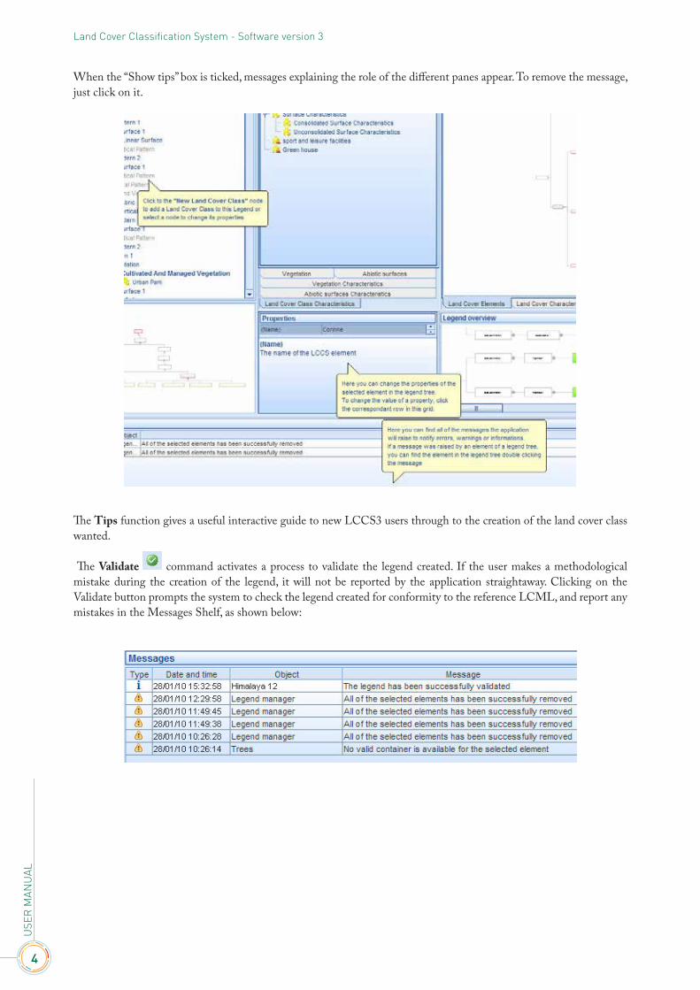
When the “Show tips” box is ticked, messages explaining the role of the different panes appear. To remove the message, just click on it.
The Tips function gives a useful interactive guide to new LCCS3 users through to the creation of the land cover class wanted.
The Validate command activates a process to validate the legend created. If the user makes a methodological mistake during the creation of the legend, it will not be reported by the application straightaway. Clicking on the Validate button prompts the system to check the legend created for conformity to the reference LCML, and report any mistakes in the Messages Shelf, as shown below:

5
1. IN
TRO
DU
CTIO
N &
BAS
IC C
ON
CEP
T
In the example below, the class “Rainfed Herbaceous Crops” contains an empty Vertical Pattern 1
After clicking on the Validation command, the system plays an “application error” sound and the following error message is reported: “A Vertical Pattern must have at least one Element”.
To amend the error reported in the example (the empty Vertical Pattern 1), either add a land cover element to it or remove the empty vertical pattern (as in the example below).

6
USE
R M
ANU
ALLand Cover Classification System - Software version 3
Clicking now on the Validation command, after correcting the error, the system plays a confirmation sound and a “Legend successfully validated” message is reported as the one in the example below.
As long as the legend does not conform to the LCCS rules, it cannot be exported or saved. Only once the legend has been validated can it be exported and saved.
1.2 - The Legend PaneAll the operations needed to create a land cover class are managed from the Legend pane. The elements in the Legend pane are in a hierarchical sequence and according to the element selected in the sequence the corresponding tool will be activated. In the example below, the “Tree Crop” class is selected; consequently the “Add a Horizontal Pattern” button is activated.
When the “Horizontal Pattern 1” element is selected, automatically the subsequent “Add a Vertical Pattern” is activated.
7
1. IN
TRO
DU
CTIO
N &
BAS
IC C
ON
CEP
T
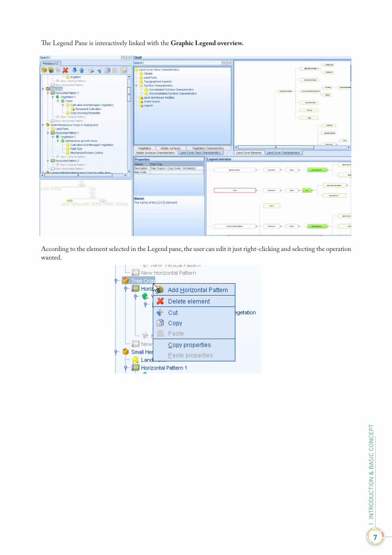
The Legend Pane is interactively linked with the Graphic Legend overview.
According to the element selected in the Legend pane, the user can edit it just right-clicking and selecting the operation wanted.

8
USE
R M
ANU
ALLand Cover Classification System - Software version 3
The buttons Expand and Collapse of the Legend toolbar allow the user to either expand or collapse all the elements contained in the selected element. An example is given below, starting from the selected element “Himalaya 12”. In this case all the classes of the legend are either expanded or collapsed.
The LCCS automatic reorder of elements button enables the automatic LCCS sort engine, which will sort the elements in the correct order based on the following LCCS rules:
• a Vertical Pattern containing vegetation elements will be placed over (before) a Vertical Pattern that contains abiotic surface elements, unless an “On Top” flag has been set;
• between vegetation elements, Woody elements will be placed over (before) Herbaceous elements, Herbaceous elements will be placed over (before) Lichen and Mosses elements, Lichen and Mosses elements will be placed over (before) Algae elements;
• between vegetation elements, derived from the same super-class, if the first element in the Vertical Pattern has a cover less than 10%:o Trees will be placed over (before) Shrubs;o Graminoids will be placed over (before) Forbs;o Mosses will be placed over (before) Lichens;
• between abiotic surface elements, Artificial Surface elements will be placed over Natural Surface elements, Natural Surface elements will be placed over Water and Associated Surfaces elements;
• between abiotic surface elements derived from the same super-class:o Built-up surfaces will be placed over Non-built up surfaceso Non-linear surfaces will be placed over Linear surfaceso Buildings will be placed over Other Constructionso Other Constructions will be placed over Other Artificial Surfaceso Consolidated Surfaces will be placed over Unconsolidated Surfaces
• all of the other elements will be placed in the same sequence used by the user.

9
1. IN
TRO
DU
CTIO
N &
BAS
IC C
ON
CEP
T
1.3 - The Diagram of the “Core Engine” pane The below diagram of the “Core Engine” pane shows how the position of an element selected in the Legend pane is displayed in the general reference UML. In the below example “Cultivated and Managed Vegetation” is selected in the Legend pane; automatically the node is highlighted with a red border in the Diagram of the “Core Engine” pane, giving the user a clear view of its position in the general reference UML.
Using the mouse scroll on the Diagram pane, it is possible to enlarge/shrink the view.
10
USE
R M
ANU
ALLand Cover Classification System - Software version 3
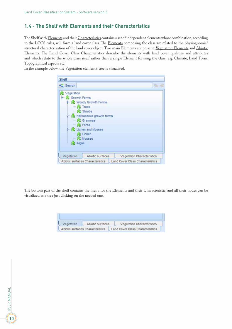
1.4 - The Shelf with Elements and their Characteristics
The Shelf with Elements and their Characteristics contains a set of independent elements whose combination, according to the LCCS rules, will form a land cover class. The Elements composing the class are related to the physiognomic/structural characterization of the land cover object. Two main Elements are present: Vegetation Elements and Abiotic Elements. The Land Cover Class Characteristics describe the elements with land cover qualities and attributes and which relate to the whole class itself rather than a single Element forming the class; e.g. Climate, Land Form, Topographical aspects etc. In the example below, the Vegetation element’s tree is visualized.
The bottom part of the shelf contains the menu for the Elements and their Characteristic, and all their nodes can be visualized as a tree just clicking on the needed one.
11
1. IN
TRO
DU
CTIO
N &
BAS
IC C
ON
CEP
T
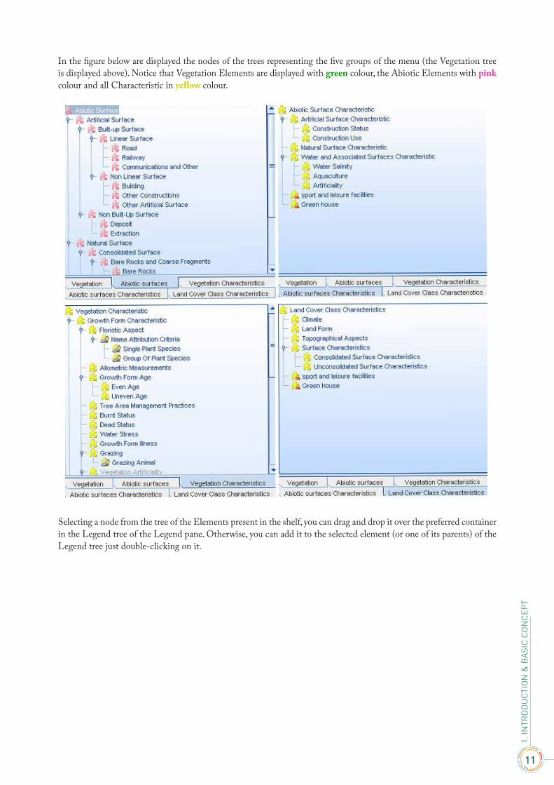
In the figure below are displayed the nodes of the trees representing the five groups of the menu (the Vegetation tree is displayed above). Notice that Vegetation Elements are displayed with green colour, the Abiotic Elements with pink colour and all Characteristic in yellow colour.
Selecting a node from the tree of the Elements present in the shelf, you can drag and drop it over the preferred container in the Legend tree of the Legend pane. Otherwise, you can add it to the selected element (or one of its parents) of the Legend tree just double-clicking on it.
12
USE
R M
ANU
ALLand Cover Classification System - Software version 3
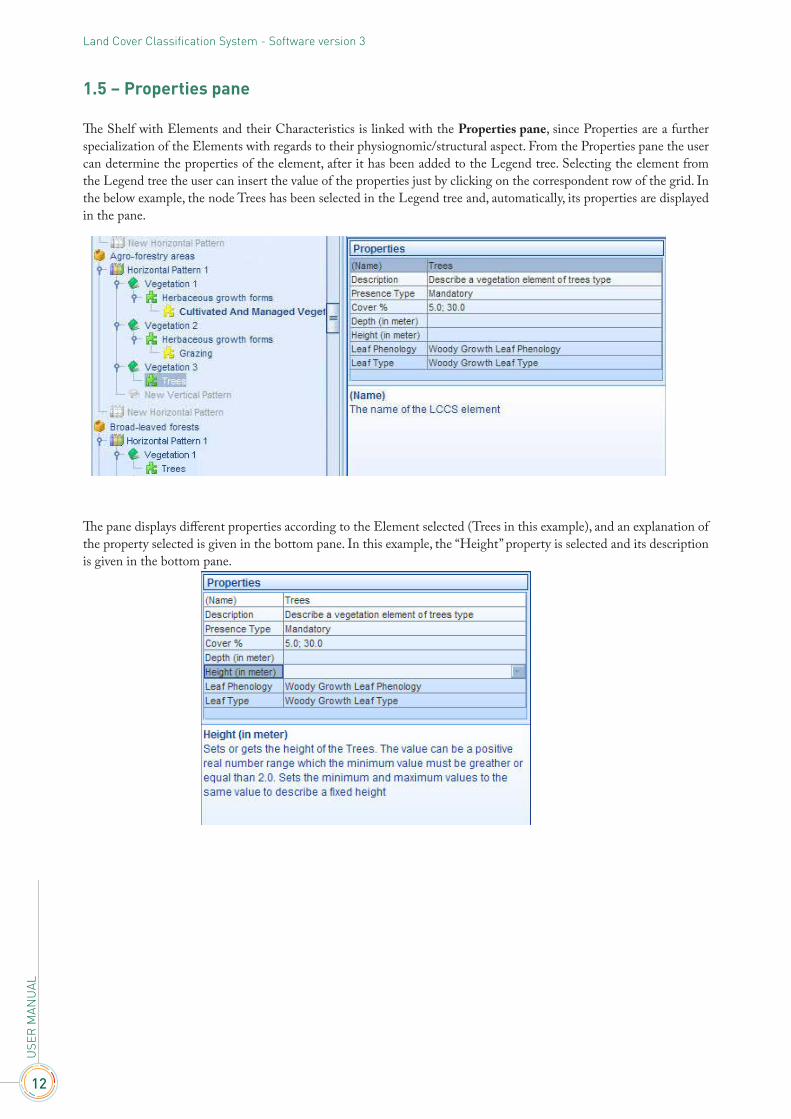
1.5 – Properties pane
The Shelf with Elements and their Characteristics is linked with the Properties pane, since Properties are a further specialization of the Elements with regards to their physiognomic/structural aspect. From the Properties pane the user can determine the properties of the element, after it has been added to the Legend tree. Selecting the element from the Legend tree the user can insert the value of the properties just by clicking on the correspondent row of the grid. In the below example, the node Trees has been selected in the Legend tree and, automatically, its properties are displayed in the pane.
The pane displays different properties according to the Element selected (Trees in this example), and an explanation of the property selected is given in the bottom pane. In this example, the “Height” property is selected and its description is given in the bottom pane.

13
1. IN
TRO
DU
CTIO
N &
BAS
IC C
ON
CEP
T
1.6 - Flowcharts & Diagrams
1. Using the mouse scroll it is possible to zoom in/out the flowcharts, starting from the point where the mouse stands.
2. Right clicking inside a flowchart the message appears, giving the option to either Print or Export it as image file. In case of printing, the printout will contain all the information stored for each node; they can be visualized by holding the mouse over the element. In the below example, the node “Trees” contains information that are not visualized in the box of the flowchart (outlined in red), but which appear if you keep the mouse on the box. This information will also appear in the printout.
3. Double-clicking on any node of the flowchart, the “LCCS elements graphic navigator” pane will pop-up. In the below example, double-clicking on the node “Ice” in the Flowchart of the Elements and their Characteristics, the window outlined with a blue dotted line will pop-up, showing the relation of the element “Ice” with all the elements that can be combined with it. Notice that the pop-up window shows only the portion of the flowchart deriving from the node selected, ignoring the upper level relations.
14
USE
R M
ANU
ALLand Cover Classification System - Software version 3
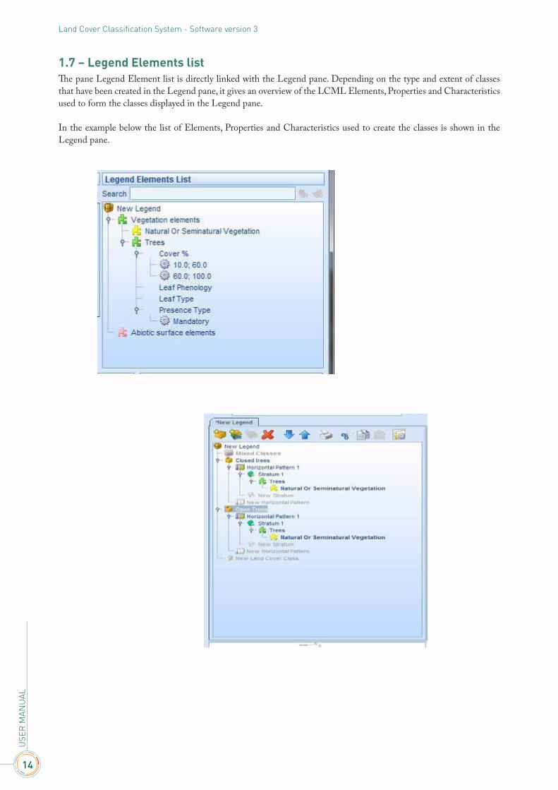
1.7 – Legend Elements listThe pane Legend Element list is directly linked with the Legend pane. Depending on the type and extent of classes that have been created in the Legend pane, it gives an overview of the LCML Elements, Properties and Characteristics used to form the classes displayed in the Legend pane.
In the example below the list of Elements, Properties and Characteristics used to create the classes is shown in the Legend pane.

15
1. IN
TRO
DU
CTIO
N &
BAS
IC C
ON
CEP
T
HOW TO CREATE A CLASS
This chapter will give practical examples of the steps to follow in order to create a class, assembling basic objects and their properties and attributes.
The preliminary steps, before the shaping of the class, are:
I. Create a new legend either clicking from the Main Toolbar on the button , or selecting it from the File Menu. More details can be given to the new legend keeping it selected and customizing its properties (Name, Description, Author etc.) from the Shelf of the Properties, as shown below.
II. Add the new land cover class by clicking either on the button (from the Legend Toolbar) or on in the Legend pane.
More details can be given to the new land cover class keeping it selected and customizing its properties (Name, Description, Map code) from the Shelf of the Properties, as shown below.
At this point you have the option to order the basic objects horizontally and/or vertically. The most common option is the ordering of basic objects (with their properties and/or characteristics) in vertical layer(s). The “horizontal pattern” option will be explained later in chapter 3.
2.1 – The build-up of the vertical Pattern (or Stratum) function
To add a Vertical Pattern (or Stratum) to the Land Cover class, the user must first define that “only” one horizontal pattern exists, selecting “Horizontal Pattern 1” by clicking either on the button
(from the Legend Toolbar) or on in the legend pane.
The Vertical Pattern (or Stratum) is the layering of different LCML basic objects or elements (Biotic and Abiotic). The Elements forming a vertical pattern are regulated by a series of functions, XOR, temporal and “on top” functions (they will be explained further in Chapter 3: ‘Rules governing LCML elements arranged in vertical strata’).
2

16
USE
R M
ANU
ALLand Cover Classification System - Software version 3
2.2 – Example 1 - Broadleaved Deciduous Natural Trees
Postulation:1. This class involves the use of only one LCML basic element (with specific properties and characteristics).2. there is no extra “Horizontal Pattern”;3. there is only one “Vertical Pattern” composed by the LCML element “trees” enriched by some Properties (i.e.,
qualities related to the physiognomic/structural characterization of the class):o Tree Cover (in this example ranging from 80 to 100%) o Leaf Type = Broadleavedo Leaf Phenology = Deciduous;
1) and one Vegetation Characteristic (i.e. quality not related to the physiognomic/structural characterization of the class) named “natural semi-natural”.
The steps to follow to create the above class are:
1) Add the “Trees” Element by double-clicking on its node from the hierarchical list of the Elements in the “Shelf with Elements and their Characteristics”. It could be added also dragging & dropping it over “Vertical Pattern 1” of the Legend tree. If the container selected in the Legend tree is not valid, a warning message will appear in the Message Shelf.
In the example below the node “Trees”, selected in the “Shelf with Elements and their Characteristics”, is going to be added to the “Vertical Pattern1”.

17
2. H
OW
TO
CR
EATE
A C
LASS
Double-clicking on the node “Trees”, this Vegetation Element is added to the “Vertical Pattern 1”, the name of which changes to “Vegetation 1”. The Shelf of elements will automatically change, displaying the tree of the Vegetation Characteristics.
2) Add the Property Cover percentage wanted (80-100%) to the “Trees” element. From the “Shelf of Properties” click on “Cover %” and then on .
A pane containing two bars (for setting the lower and the upper thresholds) will appear. The thresholds can be set manually as in the example below.
18
USE
R M
ANU
ALLand Cover Classification System - Software version 3
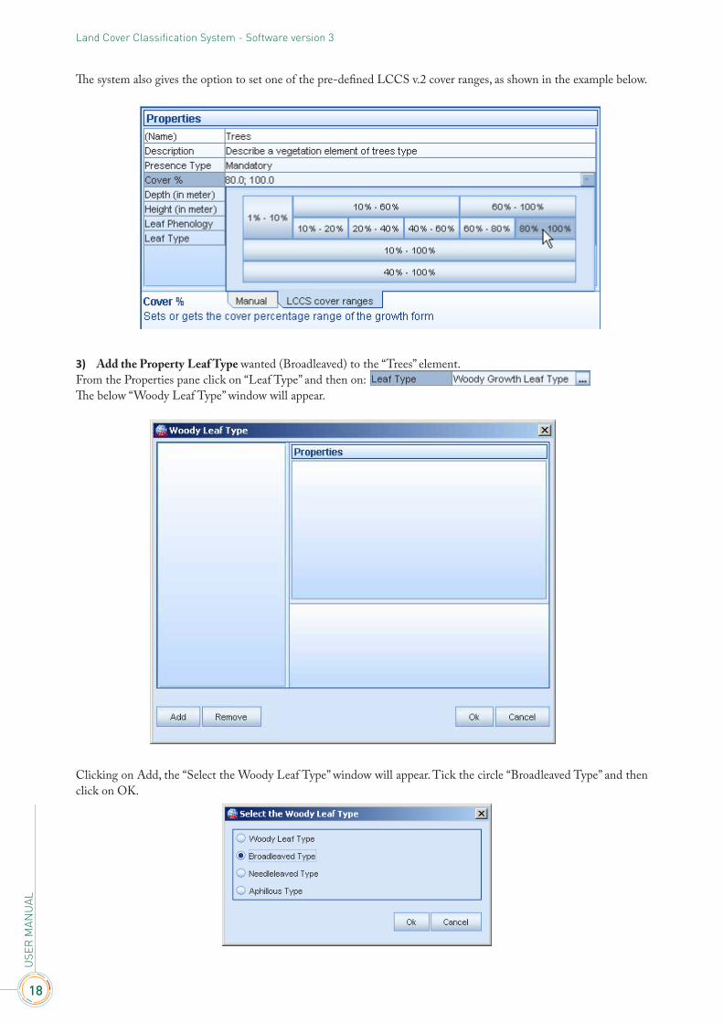
The system also gives the option to set one of the pre-defined LCCS v.2 cover ranges, as shown in the example below.
3) Add the Property Leaf Type wanted (Broadleaved) to the “Trees” element.From the Properties pane click on “Leaf Type” and then on: The below “Woody Leaf Type” window will appear.
Clicking on Add, the “Select the Woody Leaf Type” window will appear. Tick the circle “Broadleaved Type” and then click on OK.
19
2. H
OW
TO
CR
EATE
A C
LASS
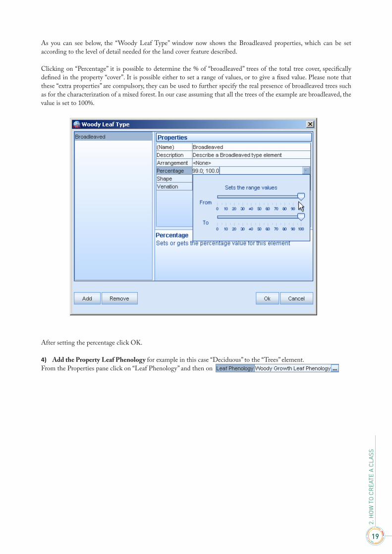
As you can see below, the “Woody Leaf Type” window now shows the Broadleaved properties, which can be set according to the level of detail needed for the land cover feature described.
Clicking on “Percentage” it is possible to determine the % of “broadleaved” trees of the total tree cover, specifically defined in the property “cover”. It is possible either to set a range of values, or to give a fixed value. Please note that these “extra properties” are compulsory, they can be used to further specify the real presence of broadleaved trees such as for the characterization of a mixed forest. In our case assuming that all the trees of the example are broadleaved, the value is set to 100%.
After setting the percentage click OK.
4) Add the Property Leaf Phenology for example in this case “Deciduous” to the “Trees” element.From the Properties pane click on “Leaf Phenology” and then on

20
USE
R M
ANU
ALLand Cover Classification System - Software version 3
The below “Woody Leaf Phenology” window will appear.
Clicking on Add, the “Select the Woody Leaf Phenology” window will appear. Tick the circle “Deciduous Leaf Phenology” and then click on OK.

21
2. H
OW
TO
CR
EATE
A C
LASS
As you can see below, the “Woody Leaf Phenology” pane now shows the “Deciduous” property, which can be set according to the level of detail needed for the land cover feature described. Clicking on “Percentage” is possible either to set a range of values, or to give a fixed value. Assuming that all the trees of the example are deciduous, the value is set to 100%.
After setting the percentage click OK.
5) Add the Vegetation Characteristic wanted (Natural Or Seminatural Vegetation) to the “Trees” element.Select “Trees” in the Legend pane. Automatically the Shelf with Elements displays the Vegetation Characteristics. Double-click on Natural Or Seminatural Vegetation.
22
USE
R M
ANU
ALLand Cover Classification System - Software version 3
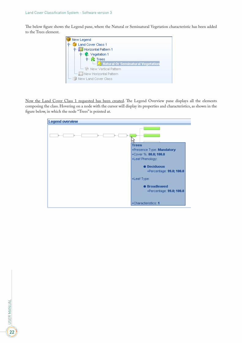
The below figure shows the Legend pane, where the Natural or Seminatural Vegetation characteristic has been added to the Trees element.
Now the Land Cover Class 1 requested has been created. The Legend Overview pane displays all the elements composing the class. Hovering on a node with the cursor will display its properties and characteristics, as shown in the figure below, in which the node “Trees” is pointed at.

23
2. H
OW
TO
CR
EATE
A C
LASS
To activate the “Elements graphic navigator” window, double-click on any node of the above “Legend overview” pane. Double-clicking on the node Trees the window will display how the trees have been described, as shown in the figure below.
Let’s now take an example describing a situation very similar to the one just described.
2.3 – Example 2 – Orchard of Apple Trees
Postulation:1. There is no extra “Horizontal Pattern”;2. there is only one “Vertical Pattern” composed by trees with the same Properties of Example 1;3. the Trees are cultivated (Apple Orchard), so they have to be described using the Vegetation Characteristic
“Cultivated and Managed”..
As can be seen from the above assumptions, the land cover class to be described is the same of the example 1, except for the fact that the LCML element “Trees” is cultivated. So, the steps of example 1 must be repeated, this time including the insertion of the “Cultivated and Managed” vegetation characteristic instead of “Natural Semi-natural”. Alternatively, instead of repeating all the steps, it is possible to copy the land cover class of Example 1, changing only the vegetation characteristic and keeping its properties given that they are exactly the same.
24
USE
R M
ANU
ALLand Cover Classification System - Software version 3
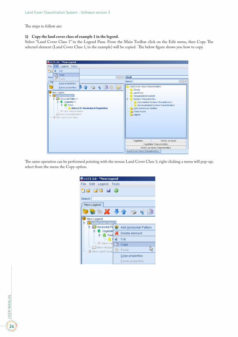
The steps to follow are:
1) Copy the land cover class of example 1 in the legend. Select “Land Cover Class 1” in the Legend Pane. From the Main Toolbar click on the Edit menu, then Copy. The selected element (Land Cover Class 1, in the example) will be copied. The below figure shows you how to copy.
The same operation can be performed pointing with the mouse Land Cover Class 1; right clicking a menu will pop-up; select from the menu the Copy option.

25
2. H
OW
TO
CR
EATE
A C
LASS
2) Paste the land cover class of example 1 in the legend. Select “New Legend” in the Legend Pane. From the Main Toolbar click on the Edit menu, then Paste. The copied element (Land Cover Class 1, in the example) will be pasted as a new land cover class in the New Legend. The below figure shows you how to paste.
The same operation can be performed pointing at “New Legend” with the mouse in the Legend Pane; right-clicking a menu will pop-up; select from the menu the Paste option.

26
USE
R M
ANU
ALLand Cover Classification System - Software version 3
Notice that if the node selected in the Legend Pane is not hierarchically correct, the function Paste will not be activated.After pasting, Land Cover Class 1 will be duplicated inside the new legend, as displayed below.
At the same time an audio confirmation message is played and a message appears in the bottom Shelf.
3) Rename the class copied. The Land Cover Class 1 just copied in the New Legend keeps the same name. To rename it, select the node
in the Legend Pane and rename it from the pane displaying its properties.
After pressing the enter key, the new class name will be displayed in the Legend Pane.

27
2. H
OW
TO
CR
EATE
A C
LASS
4) Delete the Characteristic of example 1 not fitting with the description of the present class. The Characteristic “Natural Or Seminatural Vegetation” should be removed since the class we are creating represents cultivated apple trees. To remove the Characteristic “Natural Or Seminatural Vegetation” right-click on it with the mouse and choose “Delete Element” from the menu.
5) Add the Characteristic “Cultivated And Managed Vegetation”.To add the Characteristic “Cultivated And Managed Vegetation” select the node “Trees” in the Legend Pane. The “Shelf with Elements and their Characteristics” will display all the possible Characteristics linked to the node selected; double-click on “Cultivated And Managed Vegetation”.

28
USE
R M
ANU
ALLand Cover Classification System - Software version 3
6) Add the Characteristic “Orchard and Other Plantation” To add the Characteristic “ O r c h a r d and Other Plantation” select in the Legend Pane and then double-click on in the “Shelf with Elements and their Characteristics”. The result is displayed below.
7) Add the “Apple” plant species. Select in the Legend Pane, then double –click on “Floristic Aspect” from the Vegetation Characteristics menu of the Shelf with Elements; the result is displayed below.
Keeping selected, from the Shelf of Properties select “Species Name” and scroll down the menu until
the Apple species will be displayed. Click on it.

29
2. H
OW
TO
CR
EATE
A C
LASS
Now the Land Cover Class 2 requested has been created. The Legend Overview window displays all the elements composing the class; roaming on it with the mouse, according to the node pointed, it shows its properties and its
characteristics. In the figure below, the node “Trees” is pointed at.
To activate the “Elements graphic navigator” pane, double-click on any node of the above “Legend overview” window. Double-clicking on the node Trees the pane will display how the trees have been described, as shown in the figure below.
30
USE
R M
ANU
ALLand Cover Classification System - Software version 3
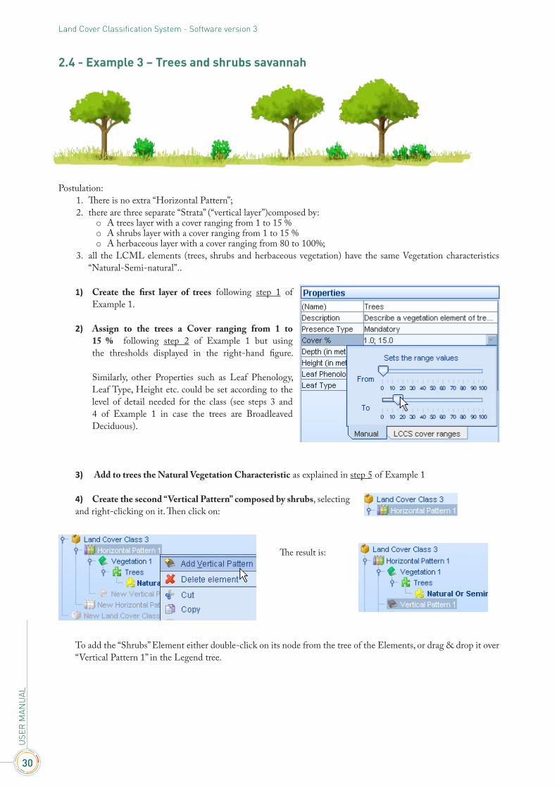
2.4 - Example 3 – Trees and shrubs savannah
Postulation:1. There is no extra “Horizontal Pattern”;2. there are three separate “Strata” (“vertical layer”)composed by:
o A trees layer with a cover ranging from 1 to 15 %o A shrubs layer with a cover ranging from 1 to 15 %o A herbaceous layer with a cover ranging from 80 to 100%;
3. all the LCML elements (trees, shrubs and herbaceous vegetation) have the same Vegetation characteristics “Natural-Semi-natural”..
1) Create the first layer of trees following step 1 of Example 1.
2) Assign to the trees a Cover ranging from 1 to 15 % following step 2 of Example 1 but using the thresholds displayed in the right-hand figure.
Similarly, other Properties such as Leaf Phenology, Leaf Type, Height etc. could be set according to the level of detail needed for the class (see steps 3 and 4 of Example 1 in case the trees are Broadleaved Deciduous).
3) Add to trees the Natural Vegetation Characteristic as explained in step 5 of Example 1
4) Create the second “Vertical Pattern” composed by shrubs, selectingand right-clicking on it. Then click on:
To add the “Shrubs” Element either double-click on its node from the tree of the Elements, or drag & drop it over “Vertical Pattern 1” in the Legend tree.
The result is:

31
2. H
OW
TO
CR
EATE
A C
LASS
In the example below the element “Shrubs” is going to be added to the “Vertical Pattern1”.Notice that the “Trees” Element is already present in “Horizontal Pattern1”.
Double-clicking on the element “Shrubs”, this Vegetation Element is added to the “Vertical Pattern 1”, the name of which appears in “Vegetation 2”. The Shelf of the Elements will automatically change, displaying the tree of the Vegetation Characteristics.
5) Assign to the shrubs a Cover ranging from 1 to 15% from the Shelf of Properties. Similarly, other Properties could be set according to the level of detail needed for the class.

32
USE
R M
ANU
ALLand Cover Classification System - Software version 3
6) Add to shrubs the Natural Vegetation Characteristic as explained in step 5 of Example 1. The result is shown below.
7) To create the third “Vertical Pattern” composed by Herbaceous vegetation, follow the same procedure of step 2, double-clicking in the Shelf of Elements on “Herbaceous growth forms” instead of “Shrubs”. The result is shown below.
8) Assign to the Herbaceous layer a Cover ranging from 80 to 100% from the Shelf of Properties. Similarly, other Properties could be set according to the level of detail needed for the class.
9) Add to the herbaceous layer the Natural Vegetation Characteristic as explained in step 5 of Example 1. The result is shown below.

33
2. H
OW
TO
CR
EATE
A C
LASS
The
Land
Cov
er C
lass 3
requ
este
d ha
s bee
n cr
eate
d fo
llowi
ng th
e in
itial
assu
mpt
ions
, as d
isplay
ed b
elow
from
the “
Elem
ents
grap
hic n
avig
ator
” win
dow
(to ac
tivat
e it s
ee E
xam
ples
1 &
2).

34
USE
R M
ANU
ALLand Cover Classification System - Software version 3
2.5 - Example 4 – Mangrove Trees
Note LCCS3 is following a pure object oriented approach. No complex definitions such as “Aquatic Vegetation”
(which were present in LCCS2), exist anymore. Therefore a situation as above will be explained by the combination of two layers: one of vegetation and one of water, as shown below.
Postulation:1. There is no extra “Horizontal Pattern”.2. There are two “Vertical Pattern” composed by:
o A layer of Mangrove trees (Vegetation)o A layer of Water (Abiotic surface)
3. The trees have the following Properties:o A cover ranging from 80 to 100 %o Leaf Type = Broadleavedo Leaf Phenology = Evergreen
4. The water has some properties:o Height ranging from 0 to 50 cmo Dynamic = with daily variationso Position = Above Surface
5. The water is moderately saline
1) Create the first layer of trees following step 1 of Example 1.2) Assign to the trees a Cover ranging from 80 to 100 % following step 2 of Example 1.3) Add the Broadleaved Leaf Type following step 3 of Example 1.4) Add the Evergreen Leaf Phenology following step4 of Example 1, selecting “Evergreen Leaf Phenology”
instead of “Deciduous Leaf Phenology” in the “Select the Woody Leaf Phenology” pane.5) Add to trees the Natural Vegetation Characteristic as explained in step 5 of Example 1.
The result is:
35
2. H
OW
TO
CR
EATE
A C
LASS
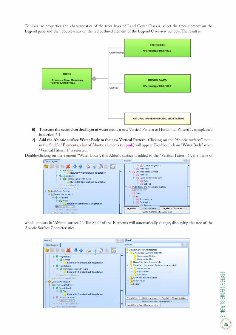
To visualize properties and characteristics of the trees layer of Land Cover Class 4, select the trees element on the Legend pane and then double-click on the red outlined element of the Legend Overview window. The result is:
6) To create the second vertical layer of water create a new Vertical Pattern to Horizontal Pattern 1, as explained in section 2.1.
7) Add the Abiotic surface Water Body to the new Vertical Pattern. Clicking on the “Abiotic surfaces” menu in the Shelf of Elements, a list of Abiotic elements (in pink) will appear. Double-click on “Water Body” when “Vertical Pattern 1” is selected.
Double-clicking on the element “Water Body”, this Abiotic surface is added to the “Vertical Pattern 1”, the name of
which appears in “Abiotic surface 1”. The Shelf of the Elements will automatically change, displaying the tree of the Abiotic Surface Characteristics.
2. H
OW
TO
CR
EATE
A C
LASS

36
USE
R M
ANU
ALLand Cover Classification System - Software version 3
8) Assign to Water Body the properties wanted from the Shelf of Properties, and keeping selected “Water Body” in the Legend pane. The result is displayed below.
9) Assign to Water Body the “Water Salinity” characteristic. Clicking on the “Abiotic surfaces Characteristics” menu in the Shelf of Elements, a list of Abiotic Characteristics (In yellow colour as for the Vegetation Characteristics) will appear. Double-click on “Water Salinity” keeping “Water Body” selected in the Legend pane.
The result is:
10) Add to Water Salinity the property “Brackish” keeping “Water Salinity” selected in the Legend pane and selecting from the “Type” menu the property wanted.
37
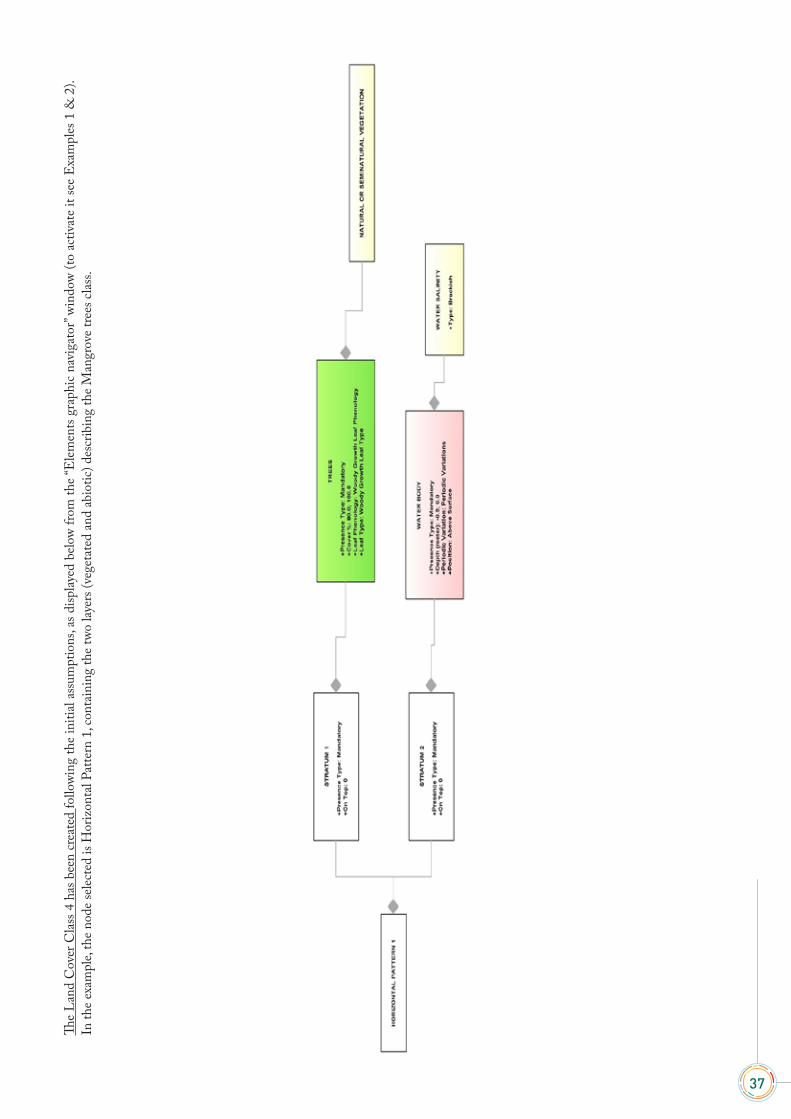
The
Land
Cov
er C
lass 4
has
bee
n cr
eate
d fo
llowi
ng th
e in
itial
assu
mpt
ions
, as d
isplay
ed b
elow
from
the “
Elem
ents
grap
hic n
avig
ator
” win
dow
(to a
ctiv
ate
it se
e E
xam
ples
1 &
2).
In th
e exa
mpl
e, th
e nod
e sele
cted
is H
oriz
onta
l Pat
tern
1, c
onta
inin
g th
e two
laye
rs (v
eget
ated
and
abio
tic) d
escr
ibin
g th
e Man
grov
e tre
es cl
ass.

38
USE
R M
ANU
ALLand Cover Classification System - Software version 3

39
2. H
OW
TO
CR
EATE
A C
LASS
RULES GOVERNING LCML ELEMENTS ARRANGED IN VERTICAL LAYERS (or STRATA)
Rules governing the organization of LCML “Elements” in vertical layers are of fundamental importance in the reference LCML schema, they can be managed in the properties pane of the LCCS v. 3.
The conceptual design of LCML is based on the fact that VEGETATED and/or ABIOTIC objects (LCML Elements) can be organized in layers to describe/characterize any type of land cover feature in the world, those layers however are governed by a series of rules to clearly define their relationship.
3.1 - Rules governing relationship of Elements inside the same layer
A stratum (“Vertical Layer”) can be composed by one or more LCML “objects”; and a land cover feature can be composed of one or more layers (or strata) respectively. Implementing one or more of these options implies the acceptance of the following rules:
Rule 1: if two or more LCML basic elements are used in the same strata the property “Occurrence” regulates their relative % of presence (occupation of the horizontal space). The sum of the “Occurrence” % cannot be more than100%.
Rule 2: the cover of each LCML element acts independently (each one can be from 0 to 100%).
Rule 3: as for rule 2 the sum of the cover of the LCML “objects” organized in different layers acts in an independent way, the sum being more than 100%.
On the basis of these rules, it is the user who decides how and if to organize LCML “objects” in the same or in different layers.
Fig. 1 shows a typical example of when it is useful to arrange LCML “objects” in different layers. A Savannah or Woodland appears composed of three separate layers of Trees, Shrubs and Herbs with different cover of the woody component depending on if it is one of the two vegetation types. The sum of the cover of the LCML “objects” of each layer can be more that 100% because each layer is independent from the other
Fig. 2 shows an example were is useful to organize two (or more) LCML “objects” in a single layer. In this case Dwarf Shrubs compete for space with the Herbs, and the whole form a single layer were the “Occurrence” of both elements determine the % of space occupied (being not more than 100%).Therefore the example in fig. 2 will be modelled in the following way:
• Element shrub, occurrence 40%, cover 40 % • Element herbs, occurrence 60%, cover 90%
As you can see for some elements (in our case shrubs) the “occurrence” % value can be the same as the “cover” % value for other (in our case herbs) the two values are different because the patches of herbs occupy 60% of the area but the cover of the plants inside the patches is very dense (90% cover). The organization of more Elements in the same stratum is not a rare case but applies to situations were two or more elements are not really separate in different strata for instance, the combination of the element “Dwarf Shrub” and an Abiotic element as “Boulders”, or the combination of houses and gardens in specific farming systems etc.
However, if Vegetated and Abiotic elements form clear separate layers they should be organized in different layers as in Fig. 3 showing a representation of a Mangrove land cover feature composed of a layer of Water and a layer of Trees.
3

40
USE
R M
ANU
ALLand Cover Classification System - Software version 3
Fig.1 Savannah woodland.
Fig. 2 Dwarf shrubs and herbs.
Fig. 3 Mangroves.
The LCML “objects” in the layer can be regulated by additional rules: • Temporal relationship • Xor relationship
Temporal relationshipIt relates two or more LCML “objects” in a layer through a temporal correlation. A user can define an LCML “object” and define through a temporal condition into which other LCML “object” it will be converted after a certain time. For instance in a nursery of Pinus trees when the plants are very young they must be classified as LCML “object” Shrubs because they are smaller than 2m, however the user can state that after a certain time (some years) this LCML “object” will become Trees. This syntax can be established in LCCS 3 putting in the same stratum the “object” Shrub and the “object” Tree linked by a temporal condition that can be set up in the pane of the “ properties”.
XOR relationshipThese types of relationships can be used when the user want to express a certain level of uncertainty in the delineation of a specific class. It is very useful when translation of classifications/legends/ based on ambiguous or unsystematic description must be done. The XOR relationships act at the level of the LCML “object” in the layer or between the different layers themselves.
At level of LCML “objects” there are three types of relationships:1. Mandatory (Fixed): the LCML “object” is always there. In effect is a default rule when the user
locates an LCML “object” in the layer.2. Exclusive implies that between two LCML “objects” a relationship A or B exist3. Optional implies that while having one LCML “object” mandatory, second one could exist in the
layer.

41
3. R
ULE
S G
OVE
RN
ING
LC
ML
ELEM
ENTS
AR
RAN
GED
IN V
ERTI
CAL
LAY
ERS
(OR
STR
ATA)
3.2- Rules governing relationship of objects in different layers
On-top functionThis function correlates objects located in two different layers, one “on top” of the other. As the default, LCML “objects” of different layers originate from the same background. In Fig. 1, for instance, the three LCML “objects” (Trees, Shrubs and Herbs) present in the three strata all originates from the same soil background. If the user needs to specify that the LCML “object” of one layer originates where the LCML ”object” of the previous layer ends, a different method must be followed. For example, a “tree roof-garden “ will be expressed in the LCML with the LCML “object” Building forming a first layer and the LCML “object” Tree forming a second layer with the function “on top”. The function can be activated in the Properties pane (see section 1.5).
Apart from the previous example (which is not common in a land cover database) this function is very useful to characterize trees with epiphytes or lianas, boulders with lichen or mosses etc.
XOR relationship between layers At layer level there are two types of XOR relationships:
1. Mandatory (Fixed): the stratum is always present. It is a default rule.2. Optional: it implies that having an LCML “object” in a stratum codified as “mandatory” (i.e. always present),
a second LCML “ object” in a second stratum codified as “optional” could exists.
This type of relationship can be used when the user wants to indicate the probable presence of a certain layer that, however, is not certain to really exist. For instance describing a forested area the user can state that the layer with LCML “object” tree (codified “mandatory”) definitely exist, while the layer with the LCML “object” shrub (codified “optional”) may or may not exist. It is useful when translation of classifications/legends/ based on ambiguous or unsystematic description are needed or when the map producer wants to indicate that a further upgrading of the information of those polygons is possible.
42
USE
R M
ANU
ALLand Cover Classification System - Software version 3
43
HOW TO CREATE A HORIZONTAL PATTERN
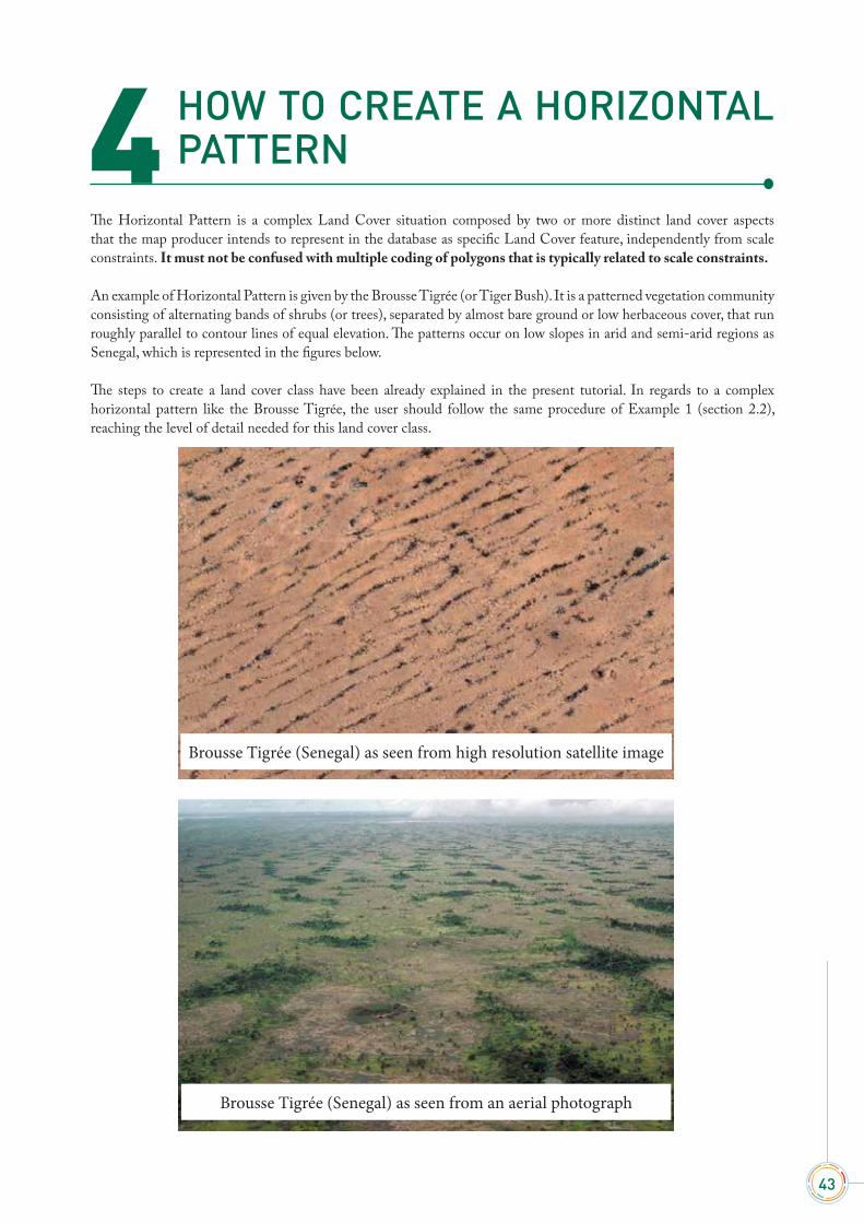
The Horizontal Pattern is a complex Land Cover situation composed by two or more distinct land cover aspects that the map producer intends to represent in the database as specific Land Cover feature, independently from scale constraints. It must not be confused with multiple coding of polygons that is typically related to scale constraints.
An example of Horizontal Pattern is given by the Brousse Tigrée (or Tiger Bush). It is a patterned vegetation community consisting of alternating bands of shrubs (or trees), separated by almost bare ground or low herbaceous cover, that run roughly parallel to contour lines of equal elevation. The patterns occur on low slopes in arid and semi-arid regions as Senegal, which is represented in the figures below.
The steps to create a land cover class have been already explained in the present tutorial. In regards to a complex horizontal pattern like the Brousse Tigrée, the user should follow the same procedure of Example 1 (section 2.2), reaching the level of detail needed for this land cover class.
Brousse Tigrée (Senegal) as seen from high resolution satellite image
Brousse Tigrée (Senegal) as seen from an aerial photograph
4

44
USE
R M
ANU
ALLand Cover Classification System - Software version 3
The difference is that instead of creating two separate land cover classes for the Shrubs and the Herbaceous vegetation, the user will describe them in two separate horizontal patterns inside the same land cover class, as displayed in the example below.
The above class “Brousse Tigrée” has been described with two separate horizontal patterns The first one is composed of a layer of natural shrubs (cover: 40-60%; height: 0-5 m) and a layer of natural herbaceous vegetation (cover: 80-100%; height: 0-1 m) while the second pattern is composed of a layer of natural herbaceous vegetation (cover: 10-20 %; height: 0-0.5 m).

45
4. H
OW
TO
CR
EATE
A H
OR
IZO
NTA
L PA
TTER
N
The c
lass j
ust d
escr
ibed
appe
ars i
n th
e “E
lemen
ts gr
aphi
c nav
igat
or” p
ane a
s fol
lows
:
46
USE
R M
ANU
ALLand Cover Classification System - Software version 3

47
4. H
OW
TO
CR
EATE
A H
OR
IZO
NTA
L PA
TTER
N
HOW TO CREATE A USER-DEFINED ATTRIBUTE
The system offers the possibility to create User-Defined characteristics. When the user creates an attribute, LCCS3 stores it in the system and make it always available for the shaping of other new classes.
Considering Example 4 (section 2.5), let’s assume that the Mangrove Trees described are situated in a Marine Reserve, and that this information is peculiar for the class description. So, if the user needs to describe this class more precisely adding also the Marine Reserve characteristic, the system allows creating this specific user-defined attribute.
In the Tools menu of the Main Toolbar select “User-defined structures manager” as displayed below.
Through the User-defined structures manager pane (displayed below) the user can create her/his own characteristic that can be attached to the element of the legend.
Let’s see the steps to follow to create a characteristic describing the Marine Reserve.
5

48
USE
R M
ANU
ALLand Cover Classification System - Software version 3
Step 1 Click in the User-defined structures manager pane. In the left column will be displayed “User Characteristic Structure 1”.
Step 2From the “General properties” window, assign the user name which will be displayed in the legend. In this case, the name “Marine Reserve” is assigned. Automatically the name changes also in the left column.
In the “General properties” pane the field “LCML type” allows the user to enter the name of the element for LCML (Land Cover Markup Language, i.e. the ISO 19144 metalanguage).
In the same pane, the “Description” field allows to enter a description of the user-defined characteristic, which could help the user to better understand its meaning. The information stored in “General properties” will be displayed as a tooltip in the Shelf of Elements and their Characteristics, as soon as the user-defined attribute has been saved and stored in the system.
Step 3In the “Target class” pane there is a list of possible classes/elements that could be chosen as goal of the user-defined attribute. In our example the target class is the water, so tick the circle next to “Abiotic water elements”.

49
5. H
OW
TO
CR
EATE
A U
SER
-DEF
INED
ATT
RIB
UTE
Automatically the system will display in the below “Target objects” pane, the elements belonging to “Water Body and Associated Surface”.
Step 4Tick the box “Water Body” in the target object pane, since the user-defined characteristic you are creating (Marine Reserve) is referred only to it and not to the other object listed.
Step 5Click on in order to describe the properties of the user-defined characteristic created. After clicking on
, the Property Settings pane, previously empty, will be displayed as in the below figure.
All the information stored in the Property Settings pane (of the User-defined structures manager pane) will appear in the Shelf of the Properties of the LCCS3 interface.

50
USE
R M
ANU
ALLand Cover Classification System - Software version 3
Step 6 In the Property Settings pane fill the field “(Name)” with the name of the setting that will be assigned to the characteristic “Marine Reserve (Typology)”, as defined by the user. It will be displayed also in the left column.
Step 7In the Property Settings pane fill the field “Description” with the description of the characteristic “Marine Reserve” defined by the user. It will be displayed in the lower part of the Shelf of the Properties of the LCCS3 interface, as description of the characteristic created.
Step 8In the Property Settings pane select the field “Property Type” and scroll through the menu. The user has the possibility to choose between different options (see below figure) according to the property of the user defined characteristic. Concerning the “Marine Reserve” characteristic, we keep the default “Text”. Actually a marine reserve could be generically defined for instance as an area of the sea which has legal protection against fishing or development which could be described better with text than numbers.

51
5. H
OW
TO
CR
EATE
A U
SER
-DEF
INED
ATT
RIB
UTE
Step 9In the Property Settings pane, select the field “Required” and scroll through the menu.
Through the field “Required”, the user sets or gets the required behavior for this property. The “Required” behavior doesn’t allow the validation of the legend if the value of the property is not set. Concerning the example “Marine Reserve” in discussion, select “Not required”.
Selecting “Always”, the user who will add the “Marine Reserve” user-defined characteristic to the “Water Body” element, is obliged to fill the field “Marine Reserve (Typology)”, otherwise the legend will not be validated and, consequently, cannot be saved.
Step 10Click in the bottom right corner of the User-defined structures manager pane.

52
USE
R M
ANU
ALLand Cover Classification System - Software version 3
Step 11 After clicking the User-defined structures manager pane will close and the characteristic created will be displayed in the Properties pane of the LCCS3 interface. Notice that newly “Marine Reserve” characteristic created is hierarchically arranged under “Water and Associated Surface Characteristic”.
Notice also that the User-defined characteristic are displayed with a different symbol compared to the other characteristics .
Step 12 The “Marine Reserve” characteristic was created in order to better describe the mangrove trees of Example 4 (section 2.5). Now we can add it to the Abiotic surface, selecting “Water Body” in the Legend pane and double-clicking on “Marine Reserve” on the Properties pane.
53
5. H
OW
TO
CR
EATE
A U
SER
-DEF
INED
ATT
RIB
UTE
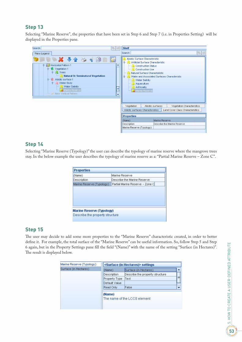
Step 13Selecting “Marine Reserve”, the properties that have been set in Step 6 and Step 7 (i.e. in Properties Setting) will be displayed in the Properties pane.
Step 14Selecting “Marine Reserve (Typology)” the user can describe the typology of marine reserve where the mangrove trees stay. In the below example the user describes the typology of marine reserve as a: “Partial Marine Reserve – Zone C”.
Step 15 The user may decide to add some more properties to the “Marine Reserve” characteristic created, in order to better define it. For example, the total surface of the “Marine Reserve” can be useful information. So, follow Step 5 and Step 6 again, but in the Property Settings pane fill the field “(Name)” with the name of the setting “Surface (in Hectares)”. The result is displayed below.

54
USE
R M
ANU
ALLand Cover Classification System - Software version 3
Step 16In the Property Settings pane select the field “Property Type” and scroll down through the menu. Concerning the property “Surface (in Hectares)” in discussion, “Positive Real Number” is selected.
Step 17 In the Property Settings pane, select the field “Required” and scroll through the menu. Concerning the property “Surface (In Hectares)” of the “Marine Reserve” characteristic in discussion, select “Not Required”, since this information is not always available.

55
5. H
OW
TO
CR
EATE
A U
SER
-DEF
INED
ATT
RIB
UTE
Step 18As soon as the “Surface (in Hectares)” property has been saved, it is displayed in the Shelf of the Properties of the LCCS3 interface. In the example below, a value of 100 was entered.
The Abiotic Surface of Example 4 (section 2.5) has been “refined” with the User-Defined characteristic “Marine Reserve” and its properties. The user may decide to add some more properties to “Marine Reserve”, following the steps just explained, and using the property type needed to describe it, i.e. Text, Numbers, Number Ranges, Enumeration (explained in Chapter 4). Below the Water Body node of Example 4 as it appears in the “Elements graphic navigator” pane is displayed:

56
USE
R M
ANU
ALLand Cover Classification System - Software version 3

57
HOW TO CREATE AN ENUMERATION FOR THE USER-DEFINED ATTRIBUTE
When the user creates a User-defined characteristic (see Chapter 3), after adding a Property to the characteristic (Chapter 3, Step 5, Step 6 and Step 7), she/he has to choose the Property Type (Chapter 3, Step 8). Scrolling through the Property type menu, among all the possible options, there is a value called Enumeration.
The present Chapter will describe how to deal with this useful option.
Enumeration is a Property Type which allows setting a list of descriptions defined by the user. One of the enumerations created will be then selected from the list, setting the Property Type. A typical example of Enumeration is the Water Salinity, from which the user can select one of the following values: Fresh, Brackish, Saline, Brine.
Let’s see now, step by step, how to create an Enumeration considering the same example of Chapter 3 (Marine Reserve). So, we will create an Enumeration Property Type for the User-defined characteristic “Marine Reserve”, assuming the existence of three types of them: International, National and Local. We also assume that both the International and National Marine Reserve belong to the category “Zone A”, while the Local Marine Reserve belongs to the category “Zone C”.
6
58
USE
R M
ANU
ALLand Cover Classification System - Software version 3
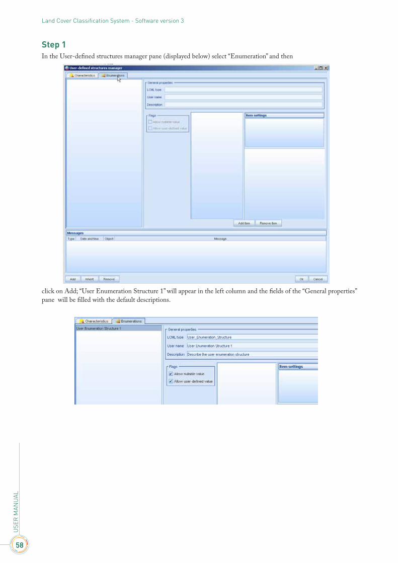
Step 1 In the User-defined structures manager pane (displayed below) select “Enumeration” and then
click on Add; “User Enumeration Structure 1” will appear in the left column and the fields of the “General properties” pane will be filled with the default descriptions.
59
6. H
OW
TO
CR
EATE
AN
EN
UM
ERAT
ION
FO
R T
HE
USE
R-D
EFIN
ED A
TTR
IBU
TE
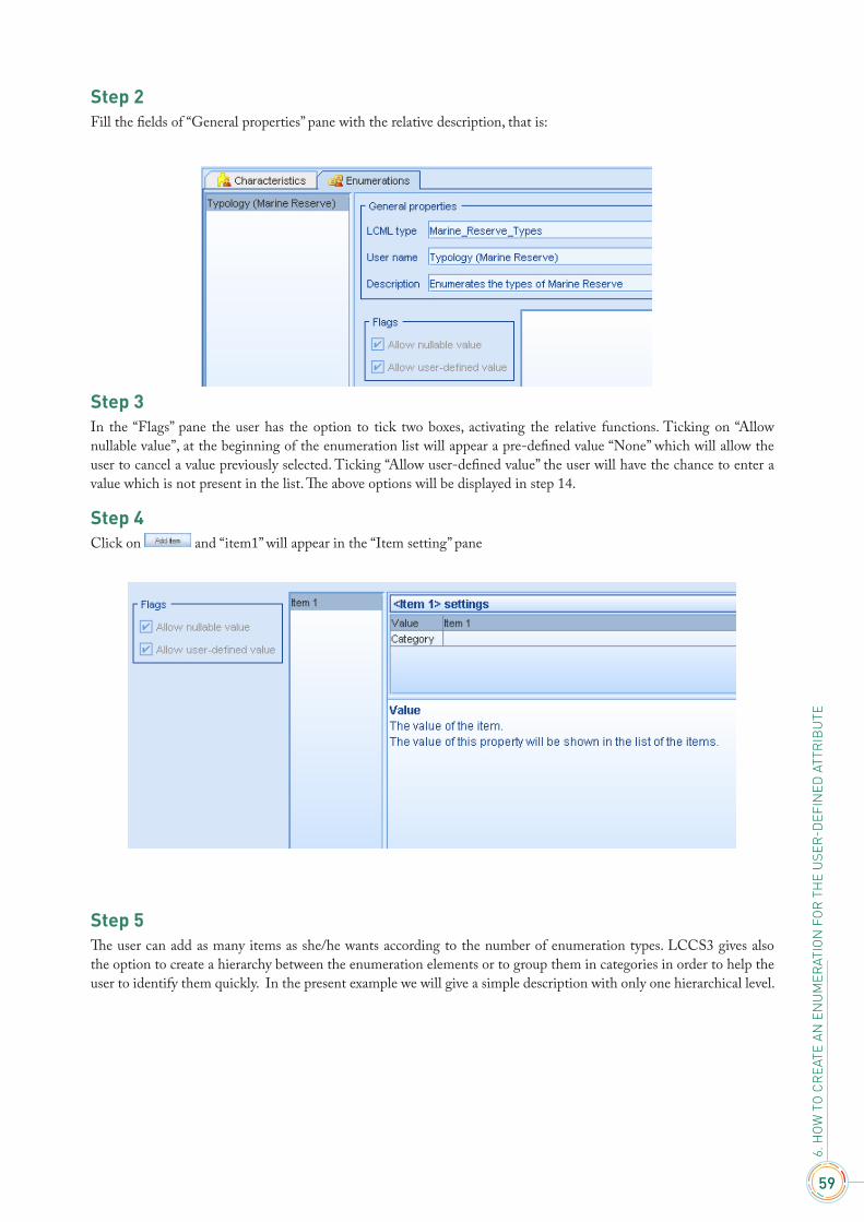
Step 2 Fill the fields of “General properties” pane with the relative description, that is:
Step 3In the “Flags” pane the user has the option to tick two boxes, activating the relative functions. Ticking on “Allow nullable value”, at the beginning of the enumeration list will appear a pre-defined value “None” which will allow the user to cancel a value previously selected. Ticking “Allow user-defined value” the user will have the chance to enter a value which is not present in the list. The above options will be displayed in step 14.
Step 4Click on and “item1” will appear in the “Item setting” pane
Step 5The user can add as many items as she/he wants according to the number of enumeration types. LCCS3 gives also the option to create a hierarchy between the enumeration elements or to group them in categories in order to help the user to identify them quickly. In the present example we will give a simple description with only one hierarchical level.
60
USE
R M
ANU
ALLand Cover Classification System - Software version 3
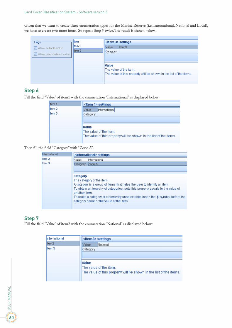
Given that we want to create three enumeration types for the Marine Reserve (i.e. International, National and Local), we have to create two more items. So repeat Step 5 twice. The result is shown below.
Step 6Fill the field “Value” of item1 with the enumeration “International” as displayed below:
Then fill the field “Category” with “Zone A”.
Step 7Fill the field “Value” of item2 with the enumeration “National” as displayed below:
61
6. H
OW
TO
CR
EATE
AN
EN
UM
ERAT
ION
FO
R T
HE
USE
R-D
EFIN
ED A
TTR
IBU
TE
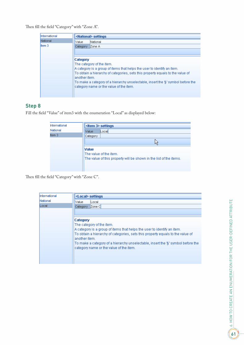
Then fill the field “Category” with “Zone A”.
Step 8Fill the field “Value” of item3 with the enumeration “Local” as displayed below:
Then fill the field “Category” with “Zone C”.
62
USE
R M
ANU
ALLand Cover Classification System - Software version 3
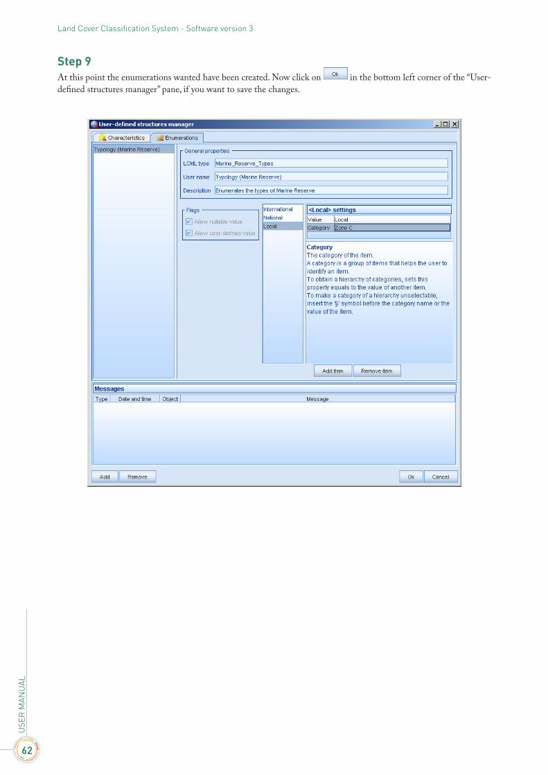
Step 9At this point the enumerations wanted have been created. Now click on in the bottom left corner of the “User-defined structures manager” pane, if you want to save the changes.

63
6. H
OW
TO
CR
EATE
AN
EN
UM
ERAT
ION
FO
R T
HE
USE
R-D
EFIN
ED A
TTR
IBU
TE
Step 10From the “User-defined structures manager” pane select “Characteristics”.
Step 11Scroll the menu of the field “Property Type” in the Property settings pane, and select “Enumeration”.

64
USE
R M
ANU
ALLand Cover Classification System - Software version 3
Step 12In the Property settings pane select the field “Default Value” and then click on .
The below “Select the enumeration” pane will pop-up, displaying the enumerations created.
65
6. H
OW
TO
CR
EATE
AN
EN
UM
ERAT
ION
FO
R T
HE
USE
R-D
EFIN
ED A
TTR
IBU
TE
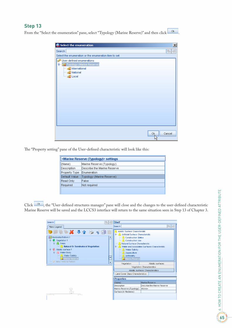
Step 13From the “Select the enumeration” pane, select “Typology (Marine Reserve)” and then click .
The “Property setting” pane of the User-defined characteristic will look like this:
Click ; the “User-defined structures manager” pane will close and the changes to the user-defined characteristic Marine Reserve will be saved and the LCCS3 interface will return to the same situation seen in Step 13 of Chapter 3.
66
USE
R M
ANU
ALLand Cover Classification System - Software version 3
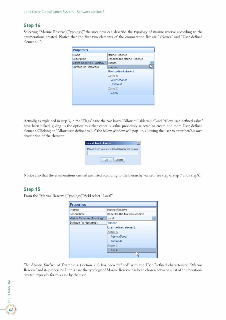
Step 14Selecting “Marine Reserve (Typology)” the user now can describe the typology of marine reserve according to the enumerations created. Notice that the first two elements of the enumeration list are “<None>” and “User-defined element…”.
Actually, as explained in step 3, in the “Flags” pane the two boxes “Allow nullable value” and “Allow user-defined value” have been ticked, giving us the option to either cancel a value previously selected or create one more User-defined element. Clicking on “Allow user-defined value” the below window will pop-up, allowing the user to enter her/his own description of the element:
Notice also that the enumerations created are listed according to the hierarchy wanted (see step 6, step 7 andv step8).
Step 15From the “Marine Reserve (Typology)” field select “Local”.
The Abiotic Surface of Example 4 (section 2.5) has been “refined” with the User-Defined characteristic “Marine Reserve” and its properties. In this case the typology of Marine Reserve has been chosen between a list of enumerations created expressly for this case by the user.
67
6. H
OW
TO
CR
EATE
AN
EN
UM
ERAT
ION
FO
R T
HE
USE
R-D
EFIN
ED A
TTR
IBU
TE
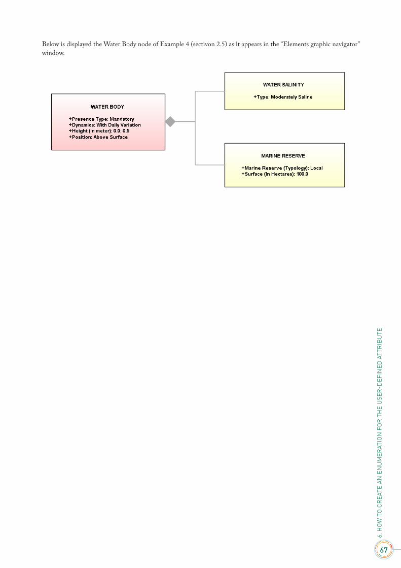
Below is displayed the Water Body node of Example 4 (sectivon 2.5) as it appears in the “Elements graphic navigator” window.

USER MANUAL
LCCS3Software version 3

Land Cover Classification System
User manual
Software version 3