landis-tn-17880 iac-2014-final - nasa · total landed mass of the system is 265 kg, somewhat less...
TRANSCRIPT

65th International Astronautical Congress, Toronto, Canada. Copyright ©2014 by the International Astronautical Federation. This work was done by employees of the United States government, and no copyright is asserted in the United States.
IAC-14,A3,P,31x26111 Page 1 of 14
IAC-14,A3,P,31x26111
ZEPHYR: A LANDSAILING ROVER FOR VENUS
Geoffrey A. Landis, Steven R. Oleson, David Grantier, and the COMPASS team NASA John Glenn Research Center, 21000 Brookpark Road, Cleveland, OH, 44135 USA
With an average temperature of 450 °C and a corrosive atmosphere at a pressure of 90 bars, the surface of Venus
is the most hostile environment of any planetary surface in the solar system. Exploring the surface of Venus would be an exciting goal, since Venus is a planet with significant scientific mysteries, and interesting geology and geophysics. Technology to operate at the environmental conditions of Venus is under development. A rover on the surface of Venus with capability comparable to the rovers that have been sent to Mars would push the limits of technology in high-temperature electronics, robotics, and robust systems. Such a rover would require the ability to traverse the landscape on extremely low power levels. We have analyzed an innovative concept for a planetary rover: a sail-propelled rover to explore the surface of Venus. Such a rover can be implemented with only two moving parts; the sail, and the steering. Although the surface wind speeds are low (under 1 m/s), at Venus atmospheric density even low wind speeds develop significant force. Under funding by the NASA Innovative Advanced Concepts office, a conceptual design for such a rover has been done. Total landed mass of the system is 265 kg, somewhat less than that of the MER rovers, with a 12 square meter rigid sail. The rover folds into a 3.6 meter aeroshell for entry into the Venus atmosphere and subsequent parachute landing on the surface. Conceptual designs for a set of high-temperature scientific instruments and a UHF communication system were done. The mission design lifetime is 50 days, allowing operation during the sunlit portion of one Venus day. Although some technology development is needed to bring the high-temperature electronics to operational readiness, the study showed that such a mobility approach is feasible, and no major difficulties are seen.
I. INTRODUCTION
Background The surface of Venus has the most hostile
environment of any planetary surface in the solar system. The average temperature of 450 °C is hotter than an oven, and the corrosive atmosphere, at a pressure of 90 bars, is difficult to withstand. Although humans have sent rovers to Mars with operating lifetimes of 8 years and counting, the Venus surface has currently been explored only by short-lived Soviet and American probes, none of which were mobile, and the longest-lived of which operated for only 2 hours on the surface before succumbing to the harsh Venus environment. Nevertheless, it is a scientifically fascinating planet, and one that, due to its similarity and differences from Earth, for which a mobile exploration rover would produce great public interest. It has been shown by missions to Mars that mobility on the surface is of great value to science exploration, and for a future mission to Venus, it is desired to be able to land a mission with a longer lifetime, and capable of mobility.
While mobility using motors capable of high temperature operations exist, the power to drive on the surface is limited by power available. Solar power is limited by the thick cloud cover, through which only ~1% of the solar illumination penetrates, and the high
temperatures, which decrease the efficiency of photovoltaic cells.
The Soviet probes, however, noted the existence of slow winds on the surface—such winds could be used for propelling a craft across the surface. While ‘tumbleweed’ type vehicles have been envisioned the Venus Landsailer design seeks to actively steer the science vehicle to avoid just getting stuck in a valley and ending the science mission. Major challenges in power production, high temperature electronics, controls, and communications must be addressed to develop a functioning Venus Landsailer.
Exploring the surface of Venus with a rover would be a “stretch” goal, which will push the limits of technology in high-temperature electronics, robotics, and robust systems. Yet it would be an exciting goal, since Venus is an unknown planet, a planet with significant scientific mysteries, and a planet larger than Mars with equally interesting (although less well known) geology and geophysics. A mission to the surface of Venus would expand our knowledge of the surfaces of terrestrial planets.
Wind on Venus
Venus is a planet with exceptional high-altitude winds, but the wind speed decreases with altitude. Nevertheless, the wind speeds at the surface are not
https://ntrs.nasa.gov/search.jsp?R=20150000879 2018-06-22T05:10:20+00:00Z
65th International Astronautical Congress, Toronto, Canada. Copyright ©2014 by the International Astronautical Federation. This work was done by employees of the United States government, and no copyright is asserted in the United States.
IAC-14,A3,P,31x26111 Page 2 of 14
zero, and the high density of the atmosphere means that, although the speeds are low, a significant amount of force is produced.
The first wind measurements on the Venus surface were done by the Soviet Venera 9 and Venera 10 landers [1,2], showing surface wind speeds in the range of 0.4 to 1.3 m/s. No anemometers were flown on later Venera landers, but wind speed was determined on two later Venera landers from acoustic measurements made by a microphone [3]. The four landers that measured surface wind speeds found average wind speed of 0.4 to 0.7 m/sec (Venera 9), 0.8 to 1.3 m/sec (Venera 10), 0.3 to 0.6 m/sec (Venera 13), and 0.3 to 0.6 m/sec (Venera 14) [4, 5]. This is a remarkably consistent surface wind of 0.6 m/sec plus or minus 0.3, (with the Venera 10 value slightly less than two standard deviations high). Wind streaks associated with craters and other landforms also indicate nonzero winds at the surface.
The speed at the surface has also been extrapolated from Doppler wind measurements of the radio signals from atmospheric descent probes, most notably the Veneras, and to a lesser extent from the Pioneer Venus Probes. The variability over a Venus day, as well as changes in direction, if any, is not known
From the Venus atmospheric density at the surface, 64.8 kg/m3 (compared to 1.225 kg/m3 at Earth’s surface), the momentum density in the wind can be estimated, and using this, the force that can be produced on a sail can be estimated.
Use of the wind to "sail" on the surface of Venus was proposed by Landis [6]. This paper analyzes in more detail the possibility of such a landsailer for Venus mobility.
Technology Background and Concept
In work to develop sensors to work inside of jet engines, electronics have been developed that will continue to function even at the Venus temperature of 450 °C, using the technology of Silicon Carbide [7-12] and Gallium Nitride [13,14]. Technology for a high-temperature switched-reluctance electric motor which operates at up to 500 °C has been developed, and is being commercialized. [15,16] These electronic components represent a breakthrough in technological capability for high temperatures. We have also tested solar cells up to Venus surface temperatures [17]. Although the power density produced is low (because of the high cloud levels and thick atmosphere), we now know that it is possible to produce electrical power on the surface. So the fundamental elements of a rover for Venus are not beyond the bounds of physics: we could survive the furnace of Venus—if we can come up with an innovative concept for a rover that can move on extremely low power levels.
The atmospheric pressure at the surface is more than 50 times greater than that of Earth. Even though the
winds at the surface of Venus are low (under 1 m/s), at Venus pressure even low wind speeds develop significant force. We have thus proposed a new concept for a planetary rover: a sail-propelled rover to explore the surface of Venus. Such a rover could open a new frontier: converting the surface of a new planet into a location that can be explored by robotic exploration.
A landsail operates on the same principle as a sailboat with wheels. The basic idea of landsailing is not new: landsailing vehicles on Earth, dating back to the “windwagons” of the 19th century to sail across the American plains. Modern landsailing vehicles are much more sophisticated; with good design they can move at speeds of up to ten times the speed of the wind. And yet the basic concept is extremely simple; using the lift force on a sail. While the detailed aerodynamic design of the sail for Venus will be somewhat different, due to the slow wind speeds but high density atmosphere, the basic design principles are well known. Most notably, a landsail can be done with only two moving parts; the sail, and the steering.
Previous Studies
This study follows several earlier studies of Venus rover designs. In 2003, a NASA Revolutionary Aerospace Systems Concepts (RASC) study “Robotic Exploration of Venus” [18] looked at the technologies needed for a future (2048) mission to Venus incorporating rovers, aircraft, and orbiters. This mission baselined use of a future radioisotope power system that would be used to both refrigerate the inside of a rover against the Venus environment, and also provide power.
In 2010, another study looked at a combination of human and robotic mission to Venus, HERRO-Venus, in which a crew vehicle in Venus orbit operates a rover on the surface via teleoperation, allowing virtual presence on the surface. For this mission, the COMPASS team did a conceptual design of a highly-capable rover design with the ability to operate for extended periods in the Venus environment [19]. While the rover vehicle designed was highly capable, the design was for a total rover mass of 1059 kg (including anticipated mass growth allowance), intended for a 2039 launch date. Like the earlier RASC study, the design study assumed the availability of Radioisotope Stirling power and cooling, which is currently being developed, and required 16 plutonium (Pu) GPHS bricks to provide the thermal input, an amount that exceeds the amount of plutonium currently available for planetary science missions. Mass and Power Growth
The COMPASS Team normally uses the AIAA S–120–2006, “Standard Mass Properties Control for Space Systems,” [20,21] as the guideline for its mass growth calculations. The COMPASS Team’s standard approach
65th International Astronautical Congress, Toronto, Canada. Copyright ©2014 by the International Astronautical Federation. This work was done by employees of the United States government, and no copyright is asserted in the United States.
IAC-14,A3,P,31x26111 Page 3 of 14
is to accommodate for a total growth of 30% or less on the dry mass of the entire system. The percent growth factors from AIAA S–120–2006 are applied to each subsystem before an additional growth is carried at the system level, in order to ensure an overall growth of 30%. Note that for designs requiring propellant, growth in the propellant mass is either carried in the propellant calculation itself or in the V used to calculate the propellant required to fly a mission.
The COMPASS Team typically uses a 30% growth on the bottoms-up power requirements of the bus subsystems when modeling the amount of required power. The power system assumptions for this study will be shown on the Power Equipment List (PEL).
II. BASELINE DESIGN Concept Drawing and Description
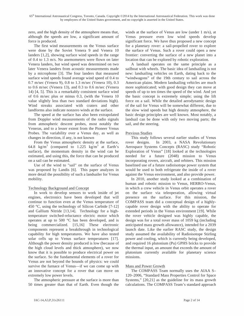
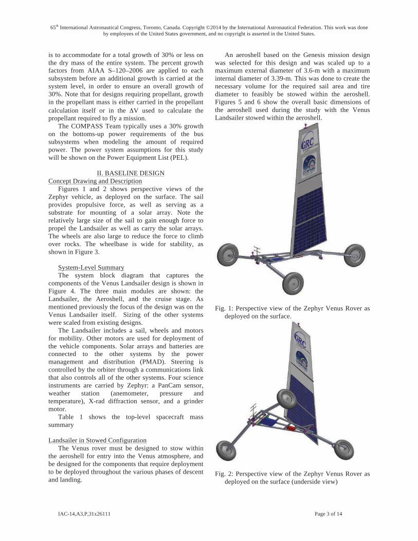
Figures 1 and 2 shows perspective views of the Zephyr vehicle, as deployed on the surface. The sail provides propulsive force, as well as serving as a substrate for mounting of a solar array. Note the relatively large size of the sail to gain enough force to propel the Landsailer as well as carry the solar arrays. The wheels are also large to reduce the force to climb over rocks. The wheelbase is wide for stability, as shown in Figure 3.
System-Level Summary The system block diagram that captures the
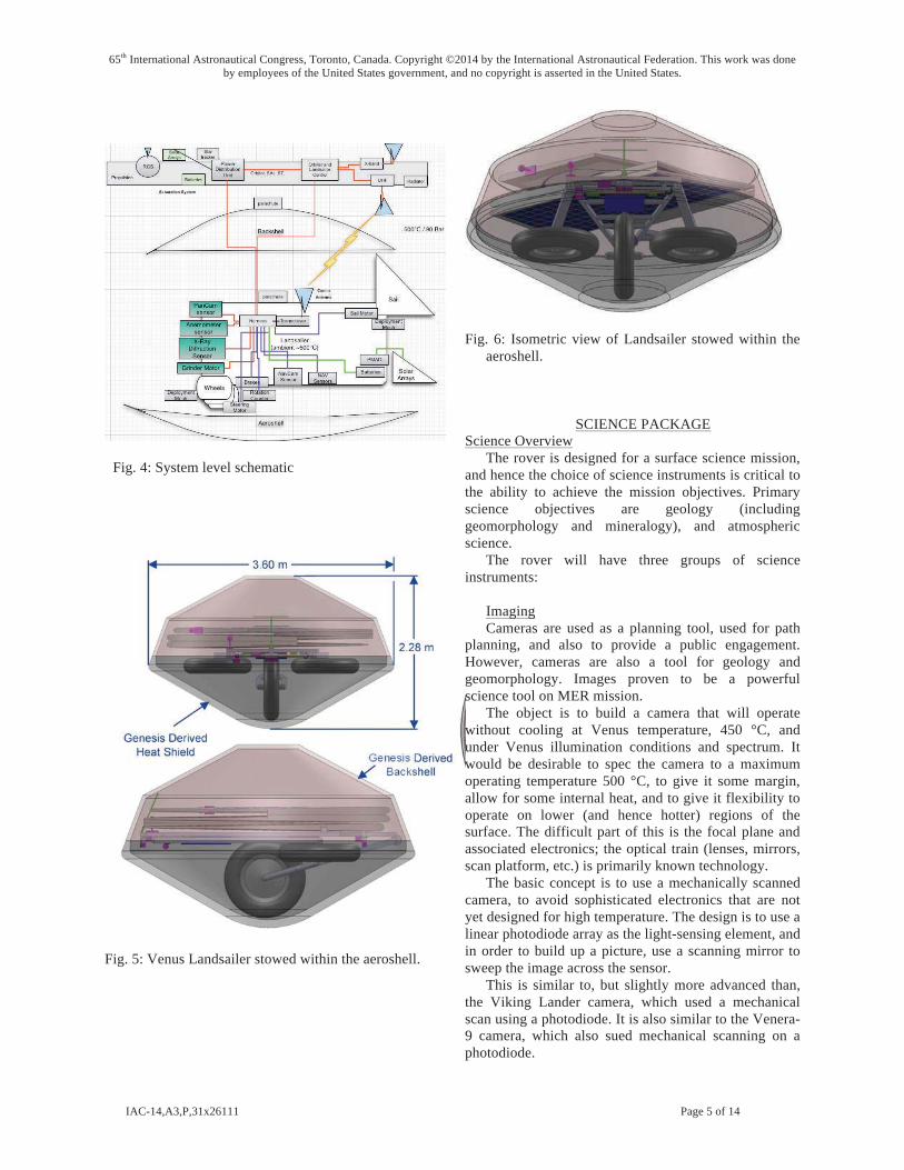
components of the Venus Landsailer design is shown in Figure 4. The three main modules are shown: the Landsailer, the Aeroshell, and the cruise stage. As mentioned previously the focus of the design was on the Venus Landsailer itself. Sizing of the other systems were scaled from existing designs.
The Landsailer includes a sail, wheels and motors for mobility. Other motors are used for deployment of the vehicle components. Solar arrays and batteries are connected to the other systems by the power management and distribution (PMAD). Steering is controlled by the orbiter through a communications link that also controls all of the other systems. Four science instruments are carried by Zephyr: a PanCam sensor, weather station (anemometer, pressure and temperature), X-rad diffraction sensor, and a grinder motor.
Table 1 shows the top-level spacecraft mass summary
Landsailer in Stowed Configuration The Venus rover must be designed to stow within
the aeroshell for entry into the Venus atmosphere, and be designed for the components that require deployment to be deployed throughout the various phases of descent and landing.
An aeroshell based on the Genesis mission design was selected for this design and was scaled up to a maximum external diameter of 3.6-m with a maximum internal diameter of 3.39-m. This was done to create the necessary volume for the required sail area and tire diameter to feasibly be stowed within the aeroshell. Figures 5 and 6 show the overall basic dimensions of the aeroshell used during the study with the Venus Landsailer stowed within the aeroshell.
Fig. 1: Perspective view of the Zephyr Venus Rover as deployed on the surface.
Fig. 2: Perspective view of the Zephyr Venus Rover as deployed on the surface (underside view)
65th International Astronautical Congress, Toronto, Canada. Copyright ©2014 by the International Astronautical Federation. This work was done by employees of the United States government, and no copyright is asserted in the United States.
IAC-14,A3,P,31x26111 Page 4 of 14
Main Subsystems Basic Mass
(kg) Growth
(kg)
Predicted Mass (kg)
Aggregate Growth
(%) Venus Landsailer System 1581.0 295.7 1877
Landsailer Rover 220.1 44.9 265 20% Science Instruments 17.9 7.0 25 39% Attitude Determination and Control 2.3 0.7 3 30% Command & Data Handling 15.3 6.3 22 41% Communications and Tracking 4.0 1.3 5 33% Electrical Power Subsystem 32.1 4.4 37 14% Thermal Control (Non-Propellant) 1.0 0.2 1 18% Propulsion (Sail System) 84.2 13.6 98 16% Propellant (Chemical) (not Used) 0.0 0 - Propulsion (EP Hardware) (Not Used) 0.0 0.0 0 - Propellant (EP) (Not Used) 0.0 0 - Structures and Mechanisms 63.2 11.4 75 18%
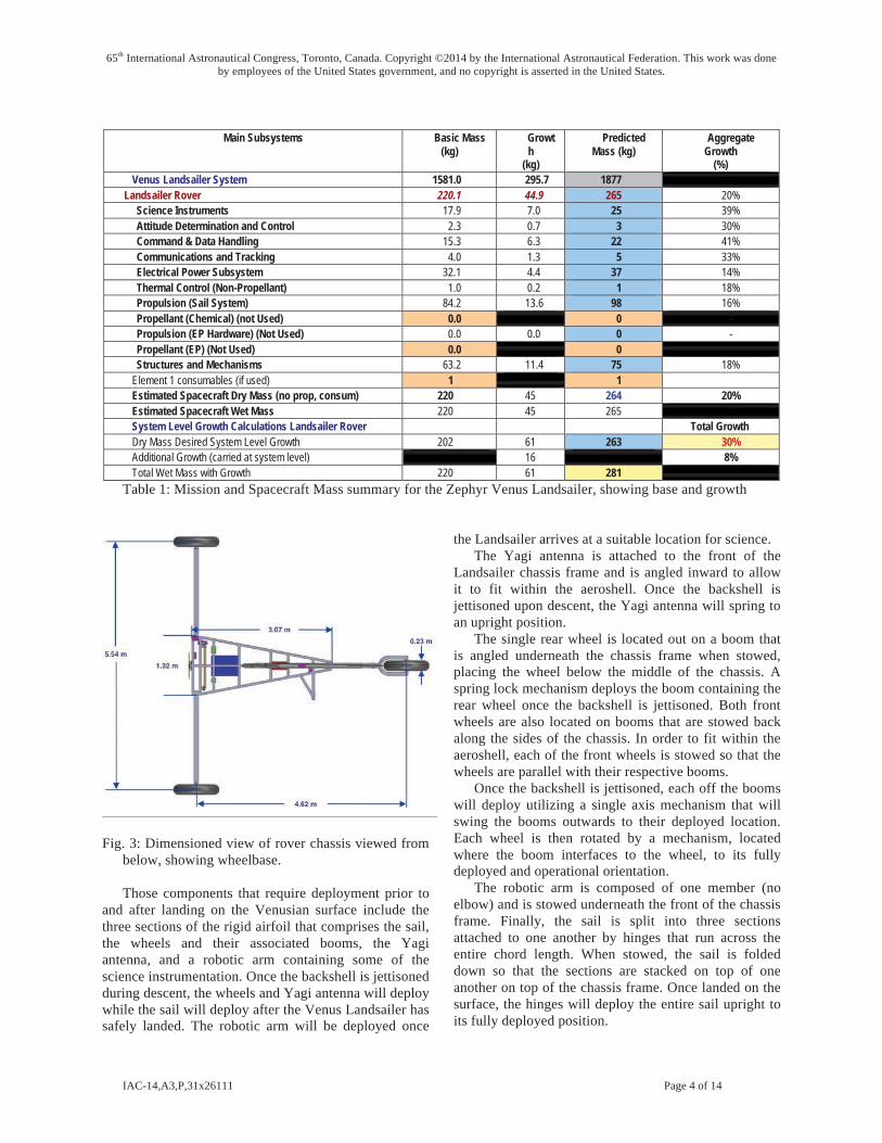
Element 1 consumables (if used) 1 1 Estimated Spacecraft Dry Mass (no prop, consum) 220 45 264 20% Estimated Spacecraft Wet Mass 220 45 265 System Level Growth Calculations Landsailer Rover Total Growth Dry Mass Desired System Level Growth 202 61 263 30% Additional Growth (carried at system level) 16 8% Total Wet Mass with Growth 220 61 281
Table 1: Mission and Spacecraft Mass summary for the Zephyr Venus Landsailer, showing base and growth
Fig. 3: Dimensioned view of rover chassis viewed from below, showing wheelbase.
Those components that require deployment prior to and after landing on the Venusian surface include the three sections of the rigid airfoil that comprises the sail, the wheels and their associated booms, the Yagi antenna, and a robotic arm containing some of the science instrumentation. Once the backshell is jettisoned during descent, the wheels and Yagi antenna will deploy while the sail will deploy after the Venus Landsailer has safely landed. The robotic arm will be deployed once
the Landsailer arrives at a suitable location for science. The Yagi antenna is attached to the front of the
Landsailer chassis frame and is angled inward to allow it to fit within the aeroshell. Once the backshell is jettisoned upon descent, the Yagi antenna will spring to an upright position.
The single rear wheel is located out on a boom that is angled underneath the chassis frame when stowed, placing the wheel below the middle of the chassis. A spring lock mechanism deploys the boom containing the rear wheel once the backshell is jettisoned. Both front wheels are also located on booms that are stowed back along the sides of the chassis. In order to fit within the aeroshell, each of the front wheels is stowed so that the wheels are parallel with their respective booms.
Once the backshell is jettisoned, each off the booms will deploy utilizing a single axis mechanism that will swing the booms outwards to their deployed location. Each wheel is then rotated by a mechanism, located where the boom interfaces to the wheel, to its fully deployed and operational orientation.
The robotic arm is composed of one member (no elbow) and is stowed underneath the front of the chassis frame. Finally, the sail is split into three sections attached to one another by hinges that run across the entire chord length. When stowed, the sail is folded down so that the sections are stacked on top of one another on top of the chassis frame. Once landed on the surface, the hinges will deploy the entire sail upright to its fully deployed position.
65th International Astronautical Congress, Toronto, Canada. Copyright ©2014 by the International Astronautical Federation. This work was done by employees of the United States government, and no copyright is asserted in the United States.
IAC-14,A3,P,31x26111 Page 5 of 14
Fig. 4: System level schematic
Fig. 5: Venus Landsailer stowed within the aeroshell.
Fig. 6: Isometric view of Landsailer stowed within the aeroshell.
SCIENCE PACKAGE Science Overview
The rover is designed for a surface science mission, and hence the choice of science instruments is critical to the ability to achieve the mission objectives. Primary science objectives are geology (including geomorphology and mineralogy), and atmospheric science.
The rover will have three groups of science instruments:
Imaging Cameras are used as a planning tool, used for path
planning, and also to provide a public engagement. However, cameras are also a tool for geology and geomorphology. Images proven to be a powerful science tool on MER mission.
The object is to build a camera that will operate without cooling at Venus temperature, 450 °C, and under Venus illumination conditions and spectrum. It would be desirable to spec the camera to a maximum operating temperature 500 °C, to give it some margin, allow for some internal heat, and to give it flexibility to operate on lower (and hence hotter) regions of the surface. The difficult part of this is the focal plane and associated electronics; the optical train (lenses, mirrors, scan platform, etc.) is primarily known technology.
The basic concept is to use a mechanically scanned camera, to avoid sophisticated electronics that are not yet designed for high temperature. The design is to use a linear photodiode array as the light-sensing element, and in order to build up a picture, use a scanning mirror to sweep the image across the sensor.
This is similar to, but slightly more advanced than, the Viking Lander camera, which used a mechanical scan using a photodiode. It is also similar to the Venera-9 camera, which also sued mechanical scanning on a photodiode.
65th International Astronautical Congress, Toronto, Canada. Copyright ©2014 by the International Astronautical Federation. This work was done by employees of the United States government, and no copyright is asserted in the United States.
IAC-14,A3,P,31x26111 Page 6 of 14
Except for the focal plane photodiode array, the design is implemented in silicon carbide electronics. The eight sensors feed into a switcher element, which consists of eight SiC transistors; the transistor for the photodiode currently being measured is “on” and the other ones “off,” and the design successively switches to each photodiode and measure it in turn until it has queried all of them. The switcher feeds the photodiode output into an op-amp, which can be a simple voltage-follower. This need not be linear (since the data can always be linearized at the receiving end), and could be just a single-transistor amplifier.
The amplifier feeds an Analog to Digital (A to D) converter,. This is to be sent to the high-temperature radio, so that the whole system has no cooled parts. Feeding this circuitry, we would also need to have an oscillator driving the switcher.
The SiC electronics used for the primary electronics are comparatively poor as photodiode material, and also operate at somewhat shorter wavelengths (near ultraviolet) than desired, given that the surface spectrum is blue deficient due to Rayleigh scattering in the thick atmosphere. The candidate material for the photodiodes is gallium-indium phosphide (GaInP2): this material is well-understood because of its use in solar cells, it has a wide enough bandgap that it will work at Venus temperature, and responds to light in the band of about 360 to 660 nm.
Weather The atmospheric science package, or Venus weather
station, comprises the following instruments. temperature sensors are assumed.
• Anemometer (wind speed and direction) • Temperature sensor • Pressure sensor In-situ mineralogy In-situ mineralogy instruments examine the
composition and mineralogy of rocks. These instruments need an instrument deployment device (“robotic arm”) to place the instruments onto rocks to determine composition and mineralogy.
Motors for mechanical parts have been designed for Venus. Drills have previously been flown to Venus on the Soviet Venera and Vega missions [7], and Honeybee Robotics has developed and tested drill and Rock Abrasion Tool (RAT) designed for Venus operation [15, 16]. The instrument placement arm (“robotic arm”) design is based on the Mars Phoenix robotic arm, but simplified to a two-joint arm, to minimize complexity.
The robotic arm instruments consist of: • Robotic arm (2 degrees of freedom) • Rock Abrasion Grinder
• Alpha Particle X-ray Spectrometer (APXS) or Energy-Dispersive Analysis by X-rays (EDAX) (composition)
• X-ray diffraction (mineralogy) Mineralogy is to be accomplished by a chemical
analysis tool to analyze composition and an X-ray diffraction tool to investigate crystal structure. Tools based on the principle of EDAX are capable tools for chemical composition. Soviet missions to Venus used X-ray fluorescence as a compositional tool. On the Mars Pathfinder and MER missions, APXS was proven to be a highly capable tool for chemical analysis of rocks. This too uses an Americium source to irradiate rocks, and then an energy-dispersive solid-state detector to analyze the X-ray fluorescence, which is characteristic of the rock composition. The emission from the radioisotope source is independent of operating temperature, however, the APXS system used for Sojourner and for the two MER rovers used a silicon X-ray detector designed for operation at low temperatures, in order to minimize dark current noise in the system. However, x-ray detectors have been made from SiC instead of silicon; the same noise floor can be achieved at a higher temperature.
A tool which is capable of analyzing not merely the composition but also the crystalline structure of minerals would be a x-ray diffraction. This requires a collimated, monochromatic x-ray source. For terrestrial use, this is typically an electron tube, however, it is also possible to use an isotope source for x-ray diffraction, although the source intensity is typically lower. Fe-55 has been used as a source for past missions, while the isotopes Am-241 and Rh-101 have also been proposed [22]. The detector for this will be an array of SiC x-ray detectors.
Descent Science
In addition to the surface science instruments, the vehicle may also have science packages that operate during descent, and may deploy stationary science instruments (e.g., a seismometer) that are not carried on the rover. These instruments were not analyzed in this study.
LANDSAILER ROVER SYSTEM MOBILITY
Zephyr Landsailer Mobility System Trades During a preliminary study, several different wing
designs were considered. There was an initial discussion concerning the use of a controllable sail or wing versus a “tumbleweed” design that would be freely blown across the surface. The tumbleweed saves the weight of the wheels, but because of the low surface wind velocity this idea was rejected. There was an additional discussion about the use of a fabric sail as opposed to a
65th International Astronautical Congress, Toronto, Canada. Copyright ©2014 by the International Astronautical Federation. This work was done by employees of the United States government, and no copyright is asserted in the United States.
IAC-14,A3,P,31x26111 Page 7 of 14
movable wing. The sail has less weight than the wing, but is harder to control and trim. Since the rover will be controlled remotely by the orbiter, a simpler control system worked in favor of the wing. The wing also provides a more stable surface on which to mount the solar cells used to power instruments on the rover.
Having selected a wing design, the question of airfoil design was then addressed. A cambered (curved) surface would produce more aerodynamic lift than a flat or symmetric design, but the control logic becomes more complicated since there is a definite suction surface and pressure surface on a cambered wing which must be properly oriented relative to the wind to generate the higher lift. A symmetric airfoil, however, is much easier to control at the sacrifice of a small amount of lift. Another idea that was discussed was the use of a movable rear flap on the wing to produce additional aerodynamic force. Once again, the added complexity in the control system and the added weight of the structure was cause for rejection, since additional lift could be achieved by simply rotating the entire wing structure relative to the base.
With the removal of the tumbleweed type rover designs, various wheel designs were evaluated as possible candidates. Since the rover is propulsively unpowered, a tracked system was removed from the trade space because it was deemed too complicated and required excessive amounts of delivered sail force to overcome the internal friction of the system. Due to the nature of the surface environment, any polymer based or inflatable system was ruled out as well. This left various metallic wheel designs, many of which were evaluated during the Apollo program for use on the Lunar Roving Vehicle (LRV) [23]. Using both the qualitative and quantitative data available for these designs, the Apollo rover wheel design was selected primarily for its low weight, low rolling coefficient, and obstacle performance. Although this design was originally for the soft sandy lunar surface, appropriate material substitutions would allow it to survive the Venusian surface environment. It is currently unclear, however, how this design will perform on the non-sandy Venus surface. The addition of traction enhancing cleats may be needed for this design, and although beyond the scope of this study, this is seen as an easy modification to the Ti cleats which cover 50% of the tread surface.
Overview: Propulsion
A vertically mounted wing serving as a rigid sail converts the local dynamic pressure from surface winds into a propulsive force. This propulsive force has to overcome both the friction produced by the wheels on the surface and the horizontal component of the rover’s weight when climbing a hill. The wheels need to be large enough to overcome small surface obstacles while still maintaining low rolling friction in order to
minimize the sail surface area required to provide adequate mobility. Steering of both the sail and the central wheel assembly is achieved by gimbals capable of operating in Venus environment, while a combination of brakes and sail feathering provide vehicle stability during science operations.
Rover System Mobility Requirements
The surface of Venus is a harsh environment for any mobility system. The average surface temperature is 455 °C (851 °F), surface pressure is 92 atmospheres (1,350 psia), and atmospheric density at the surface is 65 kg/m3 (4.06 lbm/ft3), which is approximately 65 times the density of the Earth’s atmosphere at sea level. From the limited surface data collected during the Russian Venera landing missions, the surface wind velocity is very small, on the order of 0.5 m/s (1.6 ft/s) with variations of ± 0.3 m/s (0.98 ft/s).
The mobility system utilizes surface winds for propulsion on the surface. Wheels that are large enough to overcome the expected terrain roughness, withstand the environmental conditions, provide adequate steering and braking, and have a low rolling coefficient are required for surface mobility. The very low average surface wind velocity means that even though the atmospheric density is much greater than Earth’s, the available surface dynamic pressure is quite low relative to Earth. Therefore, a relatively large sail area is required to produce enough force to move the vehicle. The sail is also required to be steerable to account for changes in wind direction and to vary its angle of attack. In an effort to save mass, the mobility system is also required to be zero fault tolerant.
Rover System Mobility Assumptions
In order to survive for any extended amount of time on the surface, it assumed that the sail, wheels, gimbal motors, actuators, and sail structure are fabricated from materials compatible with the Venus surface environment. The sail is assumed to be a rigid design in order to avoid the issues of deploying and managing a flexible high temperature fabric based system. For the purposes of propulsion, surface wind velocities of at least 0.4 m/s (1.31 ft /s) and up to 1.3 m/s (4.26 ft/s) are assumed. Based on images from Venera probes of the candidate landing site, the largest expected surface irregularities are ~10.0 cm (3.94 in) in height.
Rover System Mobility Design
The Zephyr mobility system design consists of a rigid steerable sail for propulsion, and three lunar roving vehicle (LRV) derived wheels for surface mobility which can provide both braking and steering on the surface. The wheels are 1.0 m (3.28 ft) in diameter and 22.9 cm (9.0 in.) wide.
65th International Astronautical Congress, Toronto, Canada. Copyright ©2014 by the International Astronautical Federation. This work was done by employees of the United States government, and no copyright is asserted in the United States.
IAC-14,A3,P,31x26111 Page 8 of 14
For mobility on the Venusian surface, various wheel designs were evaluated, and wheels based on the LRV wheel design were selected based on their height, low rolling friction, mass, obstacle performance, and potential environmental compatibility (assuming suitable material substitutions). The LRV wheel design consists of all metal construction with a solid main hub, a rigid cage like inner rim, and a wire mesh surface with Ti cleats. The outer mesh surface is constructed of zinc plated wire and was designed to elastically deform and change contour to help maintain good contact with the surface. This outer mesh surface can only deform until it reaches the inner rim, thus limiting its allowable elastic deformation range. It was, however, designed for a nominal deflection of 4.45 cm (1.75 in.). For use on the Venusian surface, some of the LRV wheel materials need to be replaced with suitable ones, such as 6Al4V Ti alloy. The original LRV wheel was also designed to operate on a sandy surface, while the photos from Venera show a smooth yet rocky surface akin to slate.
Motors
Although a primary propulsion does not require a motor, motors are needed to adjust the sail position, and for steering.
In order to provide steering to both the middle (aft) wheel and the sail, high temperature motors compatible with the Venusian surface environment are necessary. Unfortunately, there are currently no COTS gimbals or actuators available that meet the required environmental compatibility. Honeybee Robotics had designed and tested a motor designed to survive at temperatures above 460 °C (860 °F) in Earth atmosphere, which has been noncontinuously operated for over 20 hr in Venus surface like conditions [16]. Although designed as a high speed drill motor, it may be applicable for use in a gimbal or actuator assembly with the addition of a properly designed harmonic drive transmission.
If a new motor is required, the primary components needed to fabricate a high temperature electrical motor have been developed in the past, and would be applicable to the development of a new actuator/gimbal system for use on Venus. For example, in the early 1970s General Electric (GE) built and tested a simple electrical motor which utilized multiple high temperature material technologies [24]. The motor windings were made from nickel oxide clad silver-palladium wire 0.762 mm (0.030 in) diameter, and the poles were made from laminated 6% silicon iron. This test motor exhibited sustained operation at 575 °C (1067 °F) and operated at temperatures as high as 725 °C (1337 °F), which was the Curie temperature of silicon iron laminate core.
Although these two motors might not be suitable for use as they currently are, they prove that a fully functional motor capable of operating at (or beyond)
measured Venus surface temperatures can be built with the appropriate material substations. Given the current understanding of electrical motor design, and the demonstrated high temperature operation of these two motors, developing a gimbal or actuator for use on Venus is clearly an engineering development issue, and not one requiring a large investment in high temperature materials research.
In order to provide steering of both the central wheel and sail, a gimbal based on a commercial gimbal is used. The baseline gimbal has a 200:1 harmonic drive giving it up to 294 N-m (2,600 lbf-in) holding torque. Although this gimbal is a space rated COTS unit, it is assumed for this study that an equivalent unit can be built with materials and technology compatible with the Venusian surface environment, such as those mentioned above.
Sail
The single rigid sail used for surface propulsion is folded into three sections for storage in the aeroshell, and is deployed just prior to landing. For the purposes of this study, a symmetrical thin airfoil design was chosen, along with a trapezoidal planform that tapers from the root of the wing (at its base) to its tip. The wing is mounted perpendicular to the base and can rotate via its gimbal about its mean aerodynamic center to produce a lift (thrust) vector at any orientation to the wheels of the rover, depending on the orientation of the local wind. The wing can also be “nulled”, or set parallel to the local wind, to bring the rover to a halt, to sit in place, or avoid tipping over the rover. Construction of the wing is standard spar, rib, and skin, using materials appropriate for the corrosive high temperature environment.
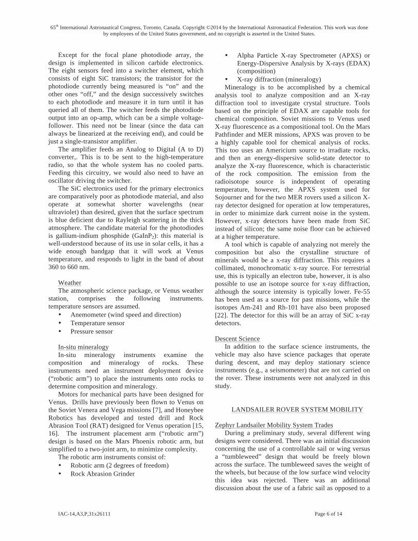
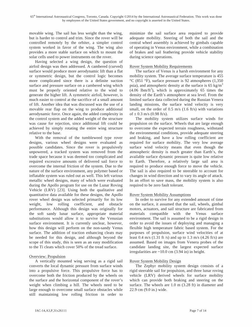
The diameter of the aeroshell sets the root chord length of the wing to be 3.10 m (10.17 ft). From the required force diagram and the lift equation described below, a total wing area of 12 m2 (129.1 ft2) is required. The resulting height of the wing is 5.44 m (17.84 ft), and is shown in a side profile vehicle in Figure 7. The sail has a constant aerodynamic cross section (no aerodynamic twist) corresponding to a NACA 0015 airfoil. The drag polar for this design was determined by using low angle of attack results from a NASA software package [25] combined with high angle of attack test data from Sandia National Laboratory [26]. The resultant drag polar is shown in Figure 8.
The rather large size of the sail relative to the rover chassis raised the concern of the vehicle toppling over during a gust of wind. Initial calculations show that assuming the rover is sitting on level ground, a wind gust hits the sail at just the right angle as to produce the maximum amount of force it could from the sail, and that the sail was at the correct angle so that all the force vector was exactly perpendicular to the rollover axis
65th International Astronautical Congress, Toronto, Canada. Copyright ©2014 by the International Astronautical Federation. This work was done by employees of the United States government, and no copyright is asserted in the United States.
IAC-14,A3,P,31x26111 Page 9 of 14
formed by one out board wheel and the center wheel, it would take a wind gust of 2.39 m/s (7.84 ft/s) to initiate a roll-over of the vehicle. The gust would need to be sustained, however, to actually cause the vehicle to topple over. The time it would take for this to occur is long enough for the sensors to recognize the situation and the control system can slack the sail, allowing it to rotate to a zero-lift position, before actual tilting occurs.
Another analysis performed during this study was to determine the performance of the wheel design over objects of various heights. This analysis assumed a solid wheel trying to roll over a rectangular object with one third of the rovers’ weight acting on the wheel in question. The results showed that a 20.0 cm (7.87 in) high obstacle could be overcome with this design given the maximum expected wind velocity of 1.30 m/s (4.26 ft/s). This does assume, however, that the force generated by the sail is exactly in line with the desired forward motion of the vehicle in overcoming the obstacle. This analysis does give some insight, but is simplistic in that the real wheels will deform somewhat around the object, thus changing their geometry slightly, and that the object can be almost any random shape, although the vertical step assumed in the analysis should represent a worst case scenario.
Sail Design With a propulsion concept selected, a trade was
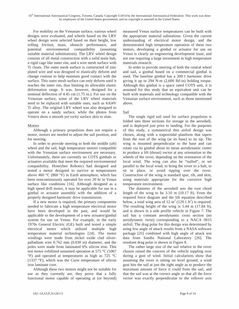
conducted to determine size of the sail given the geometric constraints of the aeroshell, the anticipated winds on the Venusian surface, and the force required to move the rover across both level terrain and an incline. For this design, it was desirable to keep the wind velocity required for sailing along level terrain near 0.3 m/s (0.98 ft/s). This allows for some margin from the 0.4 m/s (1.32 ft/s) anticipated wind velocity to account for unknowns in terrain roughness and vehicle rolling friction. Using a 1.0 m (3.28 ft) wheel diameter, a vehicle rolling friction coefficient of 0.01 (assumes nominal bearings and lunar rover derived wheels on a hard surface), and a sail force coefficient of 1.26, a parametric set of curves were calculated for various values of sail surface area. These curves, shown in figure 9, show that a sail area of 12 m2 (129.1 ft2) can propel the rover at steady state on level terrain with a wind velocity of 0.32 m/s (1.05 ft/s).
With the sail surface area determined, another trade was conducted to determine both how the current design would perform on a smooth incline, and how rover mass would affect incline performance as a function of surface wind velocity. The resulting curves show that as the mass of the rover increases, so does the required wind velocity to overcome a given slope angle. The current design requires a sustained wind velocity of approximately 1.2 m/s (3.9 ft/s) to just overcome both gravity and rolling friction on a 15° slope.
Fig. 7: Size of sail and wheels.
Fig. 8: Lift/Drag polar plot for the sail airfoil, showing total force vector (drag on the x axis, lift on the y axis) for various sail orientation to the wind.
Fig. 9: Sail force as a function of wind velocity and sail area, compared to the force required to move the vehicle.
65th International Astronautical Congress, Toronto, Canada. Copyright ©2014 by the International Astronautical Federation. This work was done by employees of the United States government, and no copyright is asserted in the United States.
IAC-14,A3,P,31x26111 Page 10 of 14
CONCEPT OF OPERATIONS (CONOPS) Interplanetary Cruise and Venus Entry During the cruise to Venus, Zephyr will remain in a
dormant state most of the time. Occasionally, it will be activated for a health check, then deactivated. This in-flight checkout would last between 3 and 4 hr and would follow as closely as possible the preprogrammed descent scenario.
Zephyr is installed on the Orbiter by a support structure with guide rails. Spring loaded pyrotechnic devices maintain Zephyr in place on the ring. An umbilical links Zephyr to the Orbiter and provides all electrical connections—power, radio frequency (RF) link, and temperature monitoring—between Zephyr and the Orbiter when they are attached during the cruise.
Prior to the Probe separation from the Orbiter, a final health-check will be performed. Upon firing at Zephyr separation, the umbilical will be disconnected and Zephyr will separate from the Orbiter with a small relative velocity of ~0.3 m/s and a spin of ~7 RPM .
Once Zephyr is released from the Orbiter it will then enter a coast phase. Zephyr will coast to Venus atmospheric entry with no possibility of changing the attitude parameters acquired at separation. At the end of the coast period, the Probe will be switched on via on-board sensing of the g-load experienced during atmospheric entry.
After Zephyr separation, the Orbiter will initiate a maneuver to avoid Venus impact, placing itself on a trajectory for Venus Orbit Insertion (VOI). On reaching VOI, the Orbiter will propulsively brake into a highly eccentric orbit around the planet. This orbit will have a 24 hr period, permitting communication with the Zephyr for 12 to 18 hr during each orbit
Zephyr Entry, Descent, and Landing
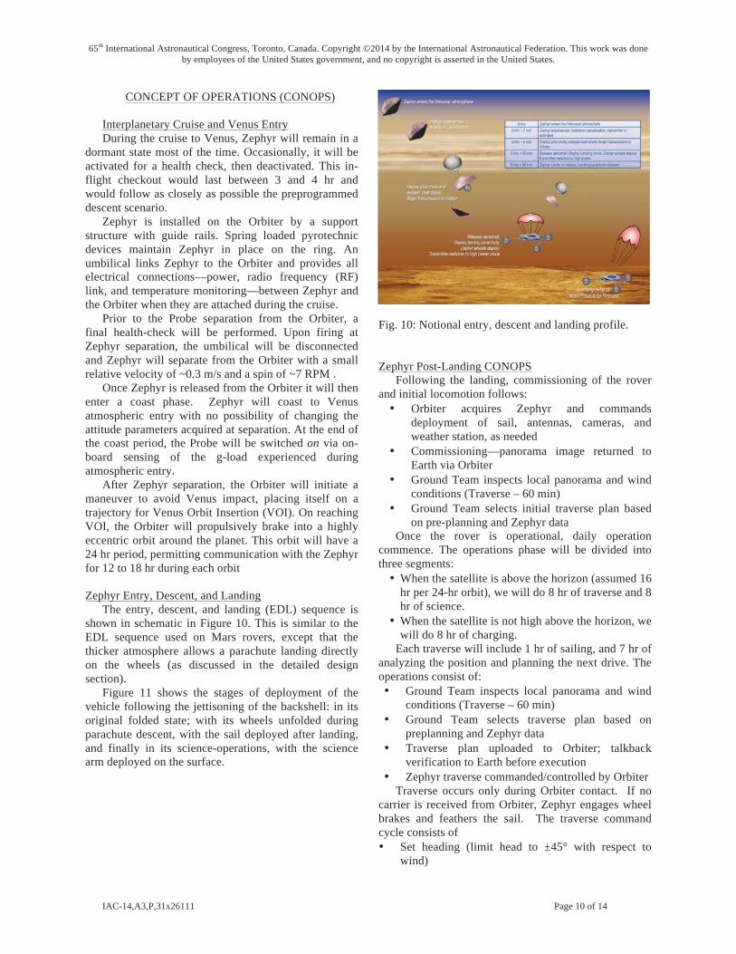
The entry, descent, and landing (EDL) sequence is shown in schematic in Figure 10. This is similar to the EDL sequence used on Mars rovers, except that the thicker atmosphere allows a parachute landing directly on the wheels (as discussed in the detailed design section).
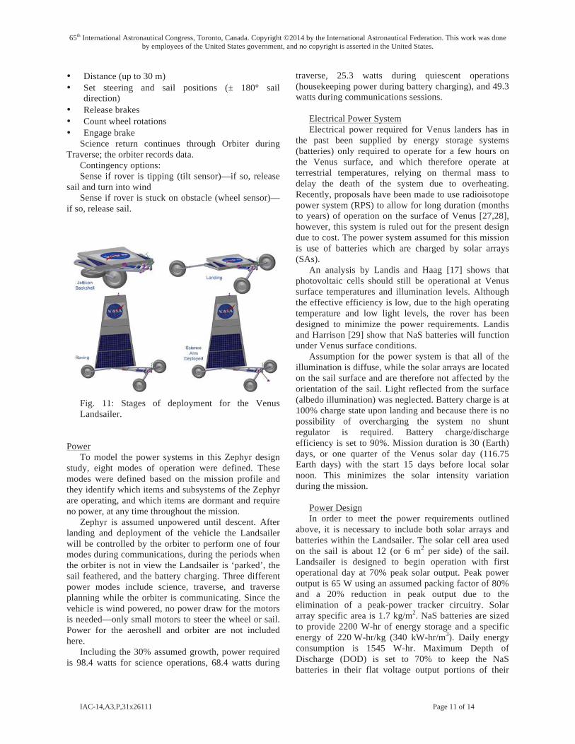
Figure 11 shows the stages of deployment of the vehicle following the jettisoning of the backshell: in its original folded state; with its wheels unfolded during parachute descent, with the sail deployed after landing, and finally in its science-operations, with the science arm deployed on the surface.
Fig. 10: Notional entry, descent and landing profile. Zephyr Post-Landing CONOPS
Following the landing, commissioning of the rover and initial locomotion follows: • Orbiter acquires Zephyr and commands
deployment of sail, antennas, cameras, and weather station, as needed
• Commissioning—panorama image returned to Earth via Orbiter
• Ground Team inspects local panorama and wind conditions (Traverse – 60 min)
• Ground Team selects initial traverse plan based on pre-planning and Zephyr data
Once the rover is operational, daily operation commence. The operations phase will be divided into three segments: • When the satellite is above the horizon (assumed 16
hr per 24-hr orbit), we will do 8 hr of traverse and 8 hr of science.
• When the satellite is not high above the horizon, we will do 8 hr of charging.
Each traverse will include 1 hr of sailing, and 7 hr of analyzing the position and planning the next drive. The operations consist of: • Ground Team inspects local panorama and wind
conditions (Traverse – 60 min) • Ground Team selects traverse plan based on
preplanning and Zephyr data • Traverse plan uploaded to Orbiter; talkback
verification to Earth before execution • Zephyr traverse commanded/controlled by Orbiter
Traverse occurs only during Orbiter contact. If no carrier is received from Orbiter, Zephyr engages wheel brakes and feathers the sail. The traverse command cycle consists of • Set heading (limit head to ±45° with respect to
wind)
65th International Astronautical Congress, Toronto, Canada. Copyright ©2014 by the International Astronautical Federation. This work was done by employees of the United States government, and no copyright is asserted in the United States.
IAC-14,A3,P,31x26111 Page 11 of 14
• Distance (up to 30 m) • Set steering and sail positions (± 180° sail
direction) • Release brakes • Count wheel rotations • Engage brake
Science return continues through Orbiter during Traverse; the orbiter records data.
Contingency options: Sense if rover is tipping (tilt sensor)—if so, release
sail and turn into wind Sense if rover is stuck on obstacle (wheel sensor)—
if so, release sail.
Fig. 11: Stages of deployment for the Venus Landsailer.
Power To model the power systems in this Zephyr design
study, eight modes of operation were defined. These modes were defined based on the mission profile and they identify which items and subsystems of the Zephyr are operating, and which items are dormant and require no power, at any time throughout the mission.
Zephyr is assumed unpowered until descent. After landing and deployment of the vehicle the Landsailer will be controlled by the orbiter to perform one of four modes during communications, during the periods when the orbiter is not in view the Landsailer is ‘parked’, the sail feathered, and the battery charging. Three different power modes include science, traverse, and traverse planning while the orbiter is communicating. Since the vehicle is wind powered, no power draw for the motors is needed—only small motors to steer the wheel or sail. Power for the aeroshell and orbiter are not included here.
Including the 30% assumed growth, power required is 98.4 watts for science operations, 68.4 watts during
traverse, 25.3 watts during quiescent operations (housekeeping power during battery charging), and 49.3 watts during communications sessions.
Electrical Power System Electrical power required for Venus landers has in
the past been supplied by energy storage systems (batteries) only required to operate for a few hours on the Venus surface, and which therefore operate at terrestrial temperatures, relying on thermal mass to delay the death of the system due to overheating. Recently, proposals have been made to use radioisotope power system (RPS) to allow for long duration (months to years) of operation on the surface of Venus [27,28], however, this system is ruled out for the present design due to cost. The power system assumed for this mission is use of batteries which are charged by solar arrays (SAs).
An analysis by Landis and Haag [17] shows that photovoltaic cells should still be operational at Venus surface temperatures and illumination levels. Although the effective efficiency is low, due to the high operating temperature and low light levels, the rover has been designed to minimize the power requirements. Landis and Harrison [29] show that NaS batteries will function under Venus surface conditions.
Assumption for the power system is that all of the illumination is diffuse, while the solar arrays are located on the sail surface and are therefore not affected by the orientation of the sail. Light reflected from the surface (albedo illumination) was neglected. Battery charge is at 100% charge state upon landing and because there is no possibility of overcharging the system no shunt regulator is required. Battery charge/discharge efficiency is set to 90%. Mission duration is 30 (Earth) days, or one quarter of the Venus solar day (116.75 Earth days) with the start 15 days before local solar noon. This minimizes the solar intensity variation during the mission.
Power Design In order to meet the power requirements outlined
above, it is necessary to include both solar arrays and batteries within the Landsailer. The solar cell area used on the sail is about 12 (or 6 m2 per side) of the sail. Landsailer is designed to begin operation with first operational day at 70% peak solar output. Peak power output is 65 W using an assumed packing factor of 80% and a 20% reduction in peak output due to the elimination of a peak-power tracker circuitry. Solar array specific area is 1.7 kg/m2. NaS batteries are sized to provide 2200 W-hr of energy storage and a specific energy of 220 W-hr/kg (340 kW-hr/m3). Daily energy consumption is 1545 W-hr. Maximum Depth of Discharge (DOD) is set to 70% to keep the NaS batteries in their flat voltage output portions of their
65th International Astronautical Congress, Toronto, Canada. Copyright ©2014 by the International Astronautical Federation. This work was done by employees of the United States government, and no copyright is asserted in the United States.
IAC-14,A3,P,31x26111 Page 12 of 14
discharge curve with an average power draw of 64.5 W. During the 8 hr rest period each day the batteries are charged.
The batteries start fully charged, discharge slightly early in the mission when the sun is low, then recharge as the sun approaches zenith, and discharge again late in the mission.
The solar cells were assumed to be on the sail, and hence oriented on a vertical plane. Placing the solar array on the deck would orient it horizontally, with the array normal aimed at the zenith. This would result in approximately double the power per unit of array area. However, since the cells can be placed on both sides of the sail, an area of sail produces roughly the same power as a horizontal array of the same area.
The constraint for the mission was to design for low cost, and hence the option of radioisotope power was ruled out. An alternate design concept using a wind turbine for power was analyzed [30], however, the large size of the sail allows a convenient surface for mounting of solar cells, allowing a simpler design.
CONCLUSIONS AND LESSONS LEARNED A rover vehicle, "Zephyr," was designed for
operation on the surface of Venus, utilizing entirely ambient-temperature electronics, and using the wind for propulsion.
These winds are harnessed by a large wing/sail which also carries the solar cells to generate power. At around 250 kg, Zephyr carries an 8 m tall airfoil sail (12
m2 area), 25 kg of science equipment (mineralogy, grinder, and weather instruments) and would return 2 Gb of science over a 30 day mission. Due to the extreme temperatures (450 °C) and pressures (90 bar) on Venus, Zephyr would have only basic control systems (based on high temperature silicon carbide (SiC) electronics) and actuators. Control would come from an orbiter which is in turn controlled from Earth. Due to the time delay from the Earth a robust control system would need to exist on the orbiter to keep Zephyr on course. Data return and control would be made using a 250 MHz link with the orbiter with a maximum data rate of 2 kbps. At the minimal wind speed required for mobility of 35 cm/s, the vehicle move at a slow but steady 4 cm/s by positioning the airfoil and use of one wheel that is steered for pointing control. Navigation commands from the orbiter will be based upon navigation cameras, simple accelerometers and stability sensors.
The conceptual study learned many lessons during the design process:
• Using a sail can provide lift—not just drag—which allows for sailing not just downwind but upwind to a certain degree.
• The wind speed is key—need at least 35 cm/s
wind, or else the vehicle needs to be redesigned with a larger sail area and/or lightened craft to enable propulsion in lower wind.
• These required wind velocities are seen in existing locations on Venus.
• Larger wheels reduce rolling friction. • Zephyr is designed to have mobility over 10 cm
debris. • Pressure vessels and cooling electronics would
be too heavy to allow sailing. • Components (especially actuators and
electronics) must be capable of operating in Venus environment (~450 °C, 90 bar, hostile atmosphere). Electronics fabricated from SiC (or an equivalent high-temperature semiconductor) is critical to operation in the environment.
• Controlling of vehicle in real-time is done from a ‘Smart’ Orbiter.
• The large sail area and low power requirements allow for solar power.
• Solar cells (0.33% effective efficiency at Venus conditions) and sodium-sulfur (NaS) batteries exist for Venus high temperatures.
ACKNOWLEDGMENTS This work was supported by the NASA Innovative
Advanced Concepts (NIAC) project at NASA Headquarters. We would like to thank Jason Derleth and Jay Falker for their support.
We would also like to acknowledge the members of the COMPASS team whose work contributed to this project: Melissa McGuire, Dave Grantier, Jen Jordan, Leslie Balkanyi, Ian Dux, Laura Burke, Rob Falck, Dave Smith, Mike Martini, Carlos Rodriguez, Jim Fittje, John Gyekenyesi, Anthony Colozza, James Fincannon, Kristen Bury, Tom Packard, Joe Warner, Glenn Williams, Jon Drexler, Mike Krasowski, Tom Benson, and Anita Tenteris.
65th International Astronautical Congress, Toronto, Canada. Copyright ©2014 by the International Astronautical Federation. This work was done by employees of the United States government, and no copyright is asserted in the United States.
IAC-14,A3,P,31x26111 Page 13 of 14
REFERENCES1. Keldysh, M. V. (1977) “Venus Exploration with the Venera 9 and Venera 10 spacecraft.” Icarus 30, pp.
605-625, 1977. 2. Basilevsky, Alexander T. and Head, James W. (2003) “The Surface of Venus,” Reports on Progress in
Physics, Vol. 66 (2003) pp. 1699–1734 PII: S0034-4885(03)08878-X 3. Ksanfomaliti, L. V., Goroshkova, N. V., and Khondyrev, V. K. , “Wind velocity at the Venus surface
according to acoustic measurements,” Kosmicheskie Issledovaniia (ISSN 0023-4206), vol. 21, Mar.-Apr. 1983, p. 218-224 (in Russian; abstract in English at http://adsabs.harvard.edu/abs/1983KosIs..21..218K)
4. Garvin, J., Head, J., Zuber M. and Helfenstein, P., “Venus: the Nature of the Surface form Venera Panoramas,” J. Geophys. Res., 89, B5, pp. 3381-3399, May 10, 1984.
5. Marov. M. Ya., “Results of Venus Missions,” Ann. Rev. Astron. Astrophys. 1978, 16, p. 157. 6. Landis, Geoffrey A. (2012) “A Landsailing Rover for Venus Mobility,” J. British Interplanetary Soc.,
Vol. 65, No. 2, 373-377 (Nov-Dec 2012). 7. Balint, T. S., Kolawa, E. A., Cutts, J. A., and Peterson, C. E., (2008) “Extreme Environment
Technologies for NASA’s Robotic Planetary Missions,” Acta Astronautica, Vol. 63, No. 3, July-August 2008, pp. 285-298. See also JPL report D-32832, Extreme Environments Technologies for Future Space Science Missions - Final Report, September 19, 2007.
8. Neudeck, P. G., Okojie, R. S., and Chen, L.-Y. (2002) “High-Temperature Electronics- A Role for Wide Bandgap Semi-conductors?” Proceedings of the IEEE, Vol. 90, 2002, pp. 1065-1076.
9. Hunter, G. W., Neudeck, P. G., Okojie, R. S., Beheim, G. M., Krasowski, M. J., Ponchak, G. E., and Chen, L.-Y. (2007) “High Temperature Electronics, Communications, and Supporting Technologies for Venus Missions,” 5th International Planetary Probe Workshop, IPPW-5, Bordeaux, France June 23-29 2007.
10. Spry, D., Neudeck, P. G., Okojie, R. S., Chen, L.-Y., Beheim, G. M., Meredith, R., Mueller, W. and Ferrier, T. L. (2004) “Electrical Operation of 6H-SiC MESFET at 500 °C for 500 Hours in Air Ambient,” Proceedings 2004 IMAPS International Conference and Exhibition on High Temperature Electronics, Santa Fe NM, 2004.
11. Spry, D., Neudeck, P. G., Chen, L.-Y., Beheim, G. M., Okojie, R. S., Chang, C. W., Meredith, R. D., Ferrier, T. L., and Evans, L. J. (2007) “Fabrication and Testing of 6H-SiC JFETs for Prolonged 500 °C Operation in Air Ambient,” in Silicon Carbide and Related Materials 2007, Materials Science Forum, T. Kimoto, ed., Trans Tech Publications, Switzerland, 2008.
12. Neudeck, P. G., Spry, D., Chen, L.-Y., Chang, C. W., Beheim, G. M., Okojie, R. S., Evans, L. J., Meredith, R. D., Ferrier, T. L., Krasowski, M. J., and Prokop, N. F. (2008) “Long-Term Characterization of 6H-SiC Transistor Integrated Circuit Technology Operating at 500 °C,” in Silicon Carbide 2008, Materials, Processing and Devices, Vol. 1069, Materials Research Society Symposium Proceedings, Materials Research Society, Warrendale, PA, 2008.
13. Son, K.-A., et al. (2010) "GaN-based high-temperature and radiation-hard electronics for harsh environments", Proc. SPIE 7679, Micro- and Nanotechnology Sensors, Systems, and Applications II, 76790U, May 05, 2010.
14. Herfurth, P., Maier, P., Men, P., Rösch, R., Lugani, L. Carlin, J-F, Grandjean, N., and Kohn, E. (2013) “GaN-on-insulator technology for high-temperature electronics beyond 400 °C,” Semiconductor Science and Technology. Vol. 28 No. 7, 2013.
15. Ji, Jerri, Narine, Roop, Kumar, Nishant, Singh, Sase, and Gorevan, Steven (2008) “High Temperature Mechanisms for Venus Exploration”, 37th COSPAR Scientific Assembly, 13-20 July 2008, Montréal, Canada., p.1370.
16. Ji, Jerri, (2008), "High Temperature Mechanisms, A Breakthrough Development," 6th International Planetary Probe Workshop, Short Course on Extreme Environment Technologies, Atlanta, Ga.
17. Landis, G. A., and Haag, E. (2013) “Analysis of Solar Cell Efficiency for Venus Atmosphere and Surface Missions” paper AIAA-2013-4028, AIAA 11th International Energy Conversion Engineering Conference, San Jose CA, July 15-17 2013.
18. Landis, Geoffrey A. (2004) “Robotic Exploration of the Surface and Atmosphere of Venus,” Acta Astronautica, Vol. 59, 7, 517-580 (October 2006); originally presented as paper IAC-04-Q.2.A.08, 55th International Astronautical Federation Congress, Vancouver BC, Oct. 4-8 2004.
19. Landis, Geoffrey A., Dyson, Rodger, Oleson, Steven J., Warner, Joseph D., Colozza, Anthony J. and Schmitz, Paul C. (2011) “Venus Rover Design Study,” paper AA 2011-7268, AIAA Space 2011 Conference & Exposition, Long Beach CA, Sept. 26-29, 2011.
65th International Astronautical Congress, Toronto, Canada. Copyright ©2014 by the International Astronautical Federation. This work was done by employees of the United States government, and no copyright is asserted in the United States.
IAC-14,A3,P,31x26111 Page 14 of 14
20. AIAA S-120-2006, AIAA Standard Mass Properties Control for Space Systems. 21. ANSI/AIAA R-020A-1999, Recommended Practice for Mass Properties Control for Satellites, Missiles,
and Launch Vehicles. 22. Stenzel, C., Schroer, C., Lengeler, B., Rasulbaev, M., and Vi, R. (2009) “Radioisotope Rh-101 as X-Ray
Source for Instruments on Space Missions,” JCPDS-International Centre for Diffraction Data 2009 ISSN 1097-0002, p. 167-174. http://www.icdd.com/resources/axa/vol52/V52_22.pdf
23. Asnani, V., Delap, D., and Greager, C., (2009), "The Development of Wheels for the Lunar Roving Vehicle," NASA/TM-- 2009-215798.
24. "A High Temperature Electric Motor, Use of Nickel-Clad Silver Palladium Wire," Platinum Metals Rev., 1971, Volume 15, Issue 3, PP. 100-101.
25. Benson, Thomas J., (1996) "Interactive Educational Tool for Classical Airfoil Theory," AIAA 97-0849, AIAA Aerospace Sciences Meeting & Exhibit, January 6-9, 1997, Reno, NV.
26. Sheldahl, Robert E. and Klimes, Paul C. (1981) "Aerodynamic Characteristics of Seven Symmetrical Airfoil Sections Through 180 Degree Angle of Attack for Use in Aerodynamic Analysis of Vertical Axis Wind Turbines," SAND80-2114, Sandia National Laboratories.
27. Landis, Geoffrey A. and Mellott, Ken (2004) “Venus Surface Power and Cooling System Design,” Acta Astronautica, Vol 61, No. 11-12, 995-1001 (Dec. 2007); originally presented as paper IAC-04-R.2.06, 55th International Astronautical Federation Congress, Vancouver BC, Oct. 4-8 2004.
28. Dyson, R. W. and Bruder, G. A. (2010) Progress Towards the Development of a Long-Lived Venus Lander Duplex System, paper AIAA–2010–6917, 8th International Energy Conversion Engineering Conference (IECEC) , Nashville, Tennessee, July 25–28, 2010; NASA/TM—2011-217018.
29. Landis, G. A. and Harrison, R. (2008) “Batteries for Venus Surface Operation,” Journal of Propulsion and Power, Vol. 26, Number 4, 649-654, July/Aug 2010; originally presented as paper AIAA-2008-5796, 6th AIAA International Energy Conversion Engineering Conf., Cleveland OH, July 28-30, 2008.
30. Benigno, G., Hoza, K., Motiwala, S., Landis G., and Colozza, A. (2013) “A Wind-powered Rover for a Low-Cost Venus Mission,” paper AIAA-2013-0586, 51st AIAA Aerospace Sciences Meeting, Grapevine TX, Jan. 7-10 2013.