landmarks commission agenda
TRANSCRIPT

LANDMARKS COMMISSION
AGENDA
cityofalbany.net
Wednesday, May 6, 2020
This meeting will be conducted remotely.
At 6:00 p.m., join the meeting from your computer, tablet, or smartphone,
by clicking the link below:
https://www.gotomeet.me/cityofalbany/landmarks
You can use your microphone or dial in using your phone.
Toll free: 1-866-899-4679
Access code/Meeting Id: 336-318-597
1. CALL TO ORDER AND PLEDGE OF ALLEGIANCE
2. ROLL CALL
3. APPROVAL OF MINUTES
a. March 4, 2020
4. SCHEDULED BUSINESS
a. Business from the Public
Persons wanting to address the commission during “business from the public” must send their written
comments by email to [email protected]. Please limit comments to one page and include your
name and address. Emails received before 5:00 p.m. on the day of the meeting will be read aloud during
“business from the public.”
b. Quasi-Judicial Public Hearing
Persons wanting to address the commission during public hearings have two options:
1. Mail or email your comments to the planner in charge of the project, Laura LaRoque,
333 Broadalbin Street SE, Albany, OR 97321; or [email protected]. Please
include your name, address, and subject of the public hearing. Comments must be received
before 5:00 p.m. on the day of the meeting in order to be considered by the commission.
2. To appear virtually during a public hearing, register by emailing [email protected]
before 5:00 p.m. on the day of the meeting. Provide your name, address, and if you are for,

LANDMARKS ADVISORY COMMISSION AGENDA Page 2 of 2
May 6, 2020
against, or neutral. During the public testimony, the chair will call upon those who have
registered to speak first, followed by any others.
▪ HI-04-20: Historic Review of New Construction of two three-story mixed-use buildings
within the Monteith National Register Historic District; 525 & 533 4th Avenue SW;
331 Calapooia Street SW. (Planner in charge Laura LaRoque at
c. Business from the Commission
5. NEXT MEETING DATE: Tuesday, May 19, 2020
6. ADJOURNMENT
Due to Governor Brown’s Executive Order No. 20-12, prohibiting public gatherings during the
COVID-19 pandemic, this meeting is accessible to the public only via phone and video connection.
Remote access information is listed at the top of this agenda.
CITY OF ALBANY
LANDMARKS COMMISSION
MINUTES Wednesday, March 4, 2020
6:00 p.m. Council Chambers, City Hall
Approved: DRAFT CALL TO ORDER AND PLEDGE OF ALLEGIANCE 6:03 p.m. Chair McQuillin called the meeting to order at 6:03 p.m. ROLL CALL Commissioners present: Kerry McQuillin; Claudia Dean; Bill Ryals; Cathy LeSuer; Keith Kolkow; Chad Robinson; Jolene Thomson Commissioners absent: Staff present: Laura LaRoque, planner III; David Martineau, planning manager; Tony Mills, planner I; Jennifer Sullivan, administrative assistant I Others Present: Camron Settlemier; David Abarr; Kim Jackson; Marlena Thomas (arrived at 6:13 p.m.)
APPROVAL OF MINUTES 6:03 p.m. Commissioner Ryals moved to approve the February 5, 2020, minutes as presented. Commissioner LeSuer seconded the motion, and it passed 7 – 0. SCHEDULED BUSINESS 6:04 p.m.
a. Welcome Commissioner Chad Robinson 6:05 p.m. Robinson introduced himself and talked about his background in the building industry.
b. Business from the Public 6:05 p.m. None
c. Business from the Commission 6:05 p.m. None
d. Election of Chair, Vice Chair, and Temporary Chair 6:05 p.m. Ryals nominated McQuillin for Chair, LeSuer seconded, a vote was taken, and the nomination passed 7-0.
Ryals nominated Kolkow for Vice-Chair, Thomson seconded, a vote was taken, and the nomination passed 7-0.
After some discussion Ryals nominated Thomson for Temporary Chair, LeSuer seconded, a vote was taken, and the nomination passed 7-0.
McQuillin reviewed the public hearing process.
e. Quasi-Judicial Public Hearing (Tony Mills) 6:10 p.m. • Marlena Thomas; 1105 1st Avenue NE
LANDMARKS COMMISSION MINUTES Page 2 of 4 March 4, 2020
♦ HI-03-20: Historic Review of Exterior Alterations to the railing for two separate exterior staircases and associated patios.
No conflicts, no ex-parte contact. Site visits declared by LeSuer and Robinson.
Meeting procedures read by Planning Manager David Martineau.
The Staff Report was presented by Planner Tony Mills. Mills provided an overview of the review criteria and hearing process (see PowerPoint).
Discussion about the substitute material request ensued.
LeSuer referenced photographs she had taken earlier in the day that showed the bottom porch siding and railing have already been removed. Mills advised that these alterations were previously approved by staff (see file no. HI-18-19).
McQuillin asked about the type of hardi-plank siding being proposed. Robinson said that he was concerned about that as well and would like clarification from the applicant.
Discussion ensued about the current railing and the proposed replacement railings. Ryals asked if the applicant would like approval for the lower railing heights instead of the height required by current building code.
The applicant, property manager Marlena Thomas said the skirting will be cedar siding not hardi-plank. Thomas said the steps and rails had to be remedied due to safety reasons and dry rotting but that worked stopped after getting the safety issues addressed. Ryals suggested the commission approve railings built to traditional railing heights instead of the height required by current building code.
Dean asked if the home is a multi-family residence. Thomas confirmed that it is a three-unit property. Ryals said that because it is residential, not commercial, an exemption can be made to have lower railing height. Ryals said it is the building official’s call, but a recommendation for lower railing heights can be made.
Further discussion ensued regarding the railing height and gaps (spacing) between rails.
McQuillin asked for public testimony.
In favor: None
Opposition: None
Neutral: Camron Settlemier commented that the agenda packet did not include the application. He said he likes the idea of the lower handrails.
Applicant rebuttal of testimony: None
Commission LeSuer asked if it is ok for the siding to be stained as opposed to painted, Thomas said it will be painted and provided a copy of the pictures of what it will look like once it is painted.
Staff response: None
Public Meeting closed 6:39 p.m.
Motion: Thomson motioned to approve including conditions to allow the height of 36 inches for the porch railing and 30 inches for the stair handrail and the siding be cedar. Kolkow seconded and the motion passed 7-0.

LANDMARKS COMMISSION MINUTES Page 3 of 4 March 4, 2020
f. Pass-Through Grant 6:43 p.m. LaRoque provided information regarding the pass-through grant and previous grant recipients. She reviewed the grant selection criteria, the grant award amount of $5,000, and timeline from application to grant receipt.
Kolkow recommended splitting the award into two amounts of $2,500. Discussion ensued about limiting the amount, funds matching by recipient, and sweat equity. The commissioners agreed that limiting the grant amount to no less than $1,000 and no more than $5,000 is the best guideline.
Commissioners would like applicants to present their projects to the Commission when applying.
LaRoque reviewed the grant scoring criteria. LeSuer asked if the funds are limited to national registry resources. LaRoque will verify. McQuillin said the commissioners should consider the flaws of the grant scoring criteria. Martineau suggested the commissioners discuss the matrix and make changes as they feel necessary. Ryals suggested using more of a checklist for applicants than a guideline for approving applications. Further discussion ensued about the grant scoring criteria, its usefulness, flaws, flexibility, and transparency. Ryals said he likes the scoring criteria but does not want to be bound by it. LeSuer recommended making the new list a question and answer form allowing applicants to provide specific information. Commissioners agreed that the grant scoring criteria should be revisited at the next meeting allowing them time to review it and make suggestions as to how to modify it.
g. Historic Preservation Month (May 2020) 7:08 p.m. McQuillin reviewed who had volunteered to head projects including displays, events, tours, and marketing.
LeSuer wants to focus on displays within hotels in Albany. She is looking for pictures and artifacts from those hotels. Ryals said he might have some St. Francis items available. Jolene offered to help with obtaining items for the displays.
The Historic preservation nomination awards will be announced at the City Council meeting on May 13, 2020 at 7:00 p.m. Discussion regarding recommendations for nominations ensued.
The commission discussed the Unseen Albany Tour, trolley tour, coloring contest, wine walk, cemetery tour, tweed ride, newsletter, and a potential historic home tour called “Back from the Brink”.
Camron Settlemier and David Abarr with Friends of Historic Albany said they will have a Farmers market booth Saturday, May 2. Camron said he will be providing a class on how to research your own house that will be limited to 15 attendees.
Items h and i on the agenda were not discussed due to time constraints. h. The conversation surrounding plans for the Historic Resource Re-Survey Project continued McQuillin
summarized the historic resource survey topics that seem to be the most important to the commissioners, including:
1. Re-survey historic resources within the districts 2. Reviewing existing records for data inconsistencies/inaccuracies and missing information 3. Update photographs of resources 4. Identify and included information on accessory structures
i. Historic designations were reviewed
LANDMARKS COMMISSION MINUTES Page 4 of 4 March 4, 2020
NEXT MEETING DATE 7:59 p.m. The next regularly scheduled meeting will be held Wednesday, April 1, 2020. (Due to COVID-19 this meeting was canceled). ADJOURNMENT 7:59 p.m. There being no other business, the meeting was adjourned at 7:59 p.m. Respectfully submitted, Reviewed by, Jennifer Sullivan Laura LaRoque Administrative Assistant Planner III
COMMUNITY DEVELOPMENT
333 Broadalbin Street SW, PO Box 490, Albany, Oregon 97321-0144 | BUILDING 541-917-7553 | PLANNING 541-917-7550
cd.cityofalbany.net
Staff Report Historic Review of New Construction
New Mixed-Use Development in Monteith National Register Historic District
File No. HI-04-20 April 29, 2020
Summary Mark and Tina Siegner have submitted a Historic Review of New Construction application for construction of two three-story mixed-use buildings on a lot within the Monteith National Register Historic District. The subject property located in the northeast corner of the Calapooia Street and Fourth Avenue intersection at 331 Calapooia Street SW, 533 Fourth Avenue SW, and 525 Fourth Avenue SW, in the Downtown Mixed Use (DMU) zoning district (Attachment A).
According to ADC 5.060, Table 5-1 Schedule of Permitted Uses, the proposed use is allowed on this property subject to approval of a Site Plan Review permit. A Site Plan Review application has been submitted and when deemed complete will be evaluated through a Type I-L review procedure for conformance with the Site Plan Review criteria contained in ADC 2.450.
As stated above, the development is proposed within the Monteith National Register Historic District. Per ADC 7.230, all new construction over 100 square feet within a historic district is subject to approval of a Historic Review of New Construction. The purpose of new construction review is to ensure that new structures are compatible with the character of the district in which they are located.
The subject application has been referred to the Landmarks Commission by the Director as permitted per ADC 1.360 and processed under a Type III review procedure in accordance with ADC 1.360. The review criteria for Historic Review of New Construction within the Monteith National Register Historic District contained in ADC 7.270(1) are addressed in this report. These criteria must be satisfied to grant approval for this application.
Application Information Review Body: Landmarks Commission (Type III review)
Staff Report Prepared By: Laura LaRoque, Project Planner
Property Owner/Applicant: Mark and Tina Siegner; 516 Kouns Drive NW, Albany, OR 97321
Architect/Representative: William Ryals; 935 Jones Avenue NW, Albany, OR 97321
Address/Location 525 & 533 Fourth Avenue SW; 331 Calapooia Street SW

HI-04-20 Staff Report April 29, 2020 Page 2 of 15
Map/Tax Lot: Linn County Assessor’s Map No.; 11S-04W-12AA Tax Lot 700
Subdivision: A portion of Lot 7 and Lot 8, Block 23, City of Albany
Zoning: Downtown Mixed Use (DMU) Zone District with Historic Overlay District (/HD); Monteith National Register Historic District
Total Land Area 10,659 square feet (0.25 acres) according to Linn County Tax Assessor’s Records
Neighborhood: Central Albany
Surrounding Zoning: North: Downtown Mixed Use (DMU) Zone District East: Downtown Mixed Use (DMU) Zone District South Hackleman Monteith (HM) District (across Fourth Ave.) West Hackleman Monteith (HM) District (across Calapooia Street)
Surrounding Uses: North: Residential Single-Family/Commercial (Fisher Funeral Home) East: Residential Single-Family South Residential Single-Family (across Fourth Ave.) West Residential Multi-Family (across Calapooia Street)
Prior Land Use History: HI-12-18 (331 Calapooia Street SW, 533 Fourth Avenue SW, and 525 Fourth Avenue SW): Demolition of three historic contributing homes in the Monteith Historic District. Demolition Permits Nos. B-1670-18/ B-1670-18/ B-1670-18.
M1-07-94 & VR-06-94: (323 and 331 Calapooia Street SW and 525 and 533 Fourth Avenue SW): Subdivision to divide two existing platted lots containing 14,752 square feet into four lots containing 3,163 square feet (Lot 1), 3,894 square feet (Lot 2), 3,260 square feet (Lot 3), and 3,511 square feet (Lot 4), with concurrent Variance to allow single family lot sizes of less than 5,000 square feet.
Notice Information On April 16, 2020, a Notice of Public Hearing was mailed to property owners within 300 feet of the subject property. On April 21, 2020, Notice of Public Hearing was also posted on the subject site. As of the date of this report, no public testimony has been received.
Analysis of Development Code Criteria Albany Development Code (ADC) criteria for Historic Review of New Construction (ADC 7.270(1)) are addressed in this report for the proposed development. The criteria must be satisfied to grant approval for this application. Code criteria are written in bold followed by findings, conclusions, and conditions of approval where conditions are necessary to meet the review criteria.
HI-04-20 Staff Report April 29, 2020 Page 3 of 15
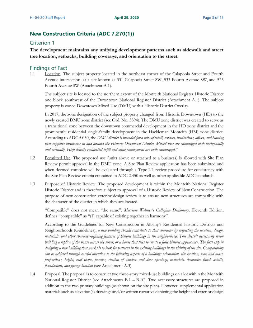
New Construction Criteria (ADC 7.270(1)) Criterion 1 The development maintains any unifying development patterns such as sidewalk and street tree location, setbacks, building coverage, and orientation to the street.
Findings of Fact 1.1 Location. The subject property located in the northeast corner of the Calapooia Street and Fourth
Avenue intersection, at a site known as 331 Calapooia Street SW, 533 Fourth Avenue SW, and 525 Fourth Avenue SW (Attachment A.1).
The subject site is located to the northern extent of the Monteith National Register Historic District one block southwest of the Downtown National Register District (Attachment A.1). The subject property is zoned Downtown Mixed Use (DMU) with a Historic District Overlay.
In 2017, the zone designation of the subject property changed from Historic Downtown (HD) to the newly created DMU zone district (see Ord. No. 5894). The DMU zone district was created to serve as a transitional zone between the downtown commercial development in the HD zone district and the prominently residential single-family development in the Hackleman Monteith (HM) zone district. According to ADC 5.030, the DMU district is intended for a mix of retail, services, institutions, offices, and housing that supports businesses in and around the Historic Downtown District. Mixed uses are encouraged both horizontally and vertically. High-density residential infill and office employment are both encouraged.”
1.2 Permitted Use. The proposed use (units above or attached to a business) is allowed with Site Plan Review permit approval in the DMU zone. A Site Plan Review application has been submitted and when deemed complete will be evaluated through a Type I-L review procedure for consistency with the Site Plan Review criteria contained in ADC 2.450 as well as other applicable ADC standards.
1.3 Purpose of Historic Review. The proposed development is within the Monteith National Register Historic District and is therefore subject to approval of a Historic Review of New Construction. The purpose of new construction exterior design review is to ensure new structures are compatible with the character of the district in which they are located.
“Compatible” does not mean “the same”. Merriam Webster’s Collegiate Dictionary, Eleventh Edition, defines “compatible” as “(1) capable of existing together in harmony”.
According to the Guidelines for New Construction in Albany’s Residential Historic Districts and Neighborhoods (Guidelines), a new building should contribute to that character by respecting the location, design, materials, and other character-defining features of historic buildings in the neighborhood. This doesn’t necessarily mean building a replica of the house across the street, or a house that tries to create a false historic appearance. The first step in designing a new building that works is to look for patterns in the existing buildings in the vicinity of the site. Compatibility can be achieved through careful attention to the following aspects of a building: orientation, site location, scale and mass, proportions, height, roof shape, porches, rhythm of window and door openings, materials, decorative finish details, foundations, and garage location (see Attachment A.3)
1.4 Proposal. The proposal is to construct two three-story mixed-use buildings on a lot within the Monteith National Register District (see Attachments B.1 – B.10). Two accessory structures are proposed in addition to the two primary buildings (as shown on the site plan). However, supplemental application materials such as elevation(s) drawings and/or written narrative depicting the height and exterior design
HI-04-20 Staff Report April 29, 2020 Page 4 of 15
of the accessory structures was not provided with this application submittal. Therefore, a condition of approval will ensure a subsequent review of said accessory structure(s).
1.5 Orientation. Most historic buildings in the district squarely face a street, with their principal facade and entrance in full view. For buildings on corner lots, entrances may be located on each principal façade or at the corner to anchor the intersection and to capture pedestrian activity from both street frontages. Likewise, new buildings within the district should be oriented to the street with main entryways along these principal facades.
The historic development pattern in the district and block of the proposed development is consistent with current design standards and main entrance design standards in ADC 8.265. The principal facades of commercial enterprises in the block and near vicinity are oriented to the abutting streets with main entrances facing the street or corner intersection. The residences on the subject block and across the streets from the proposed development all squarely face and have primary facades oriented towards the abutting street.
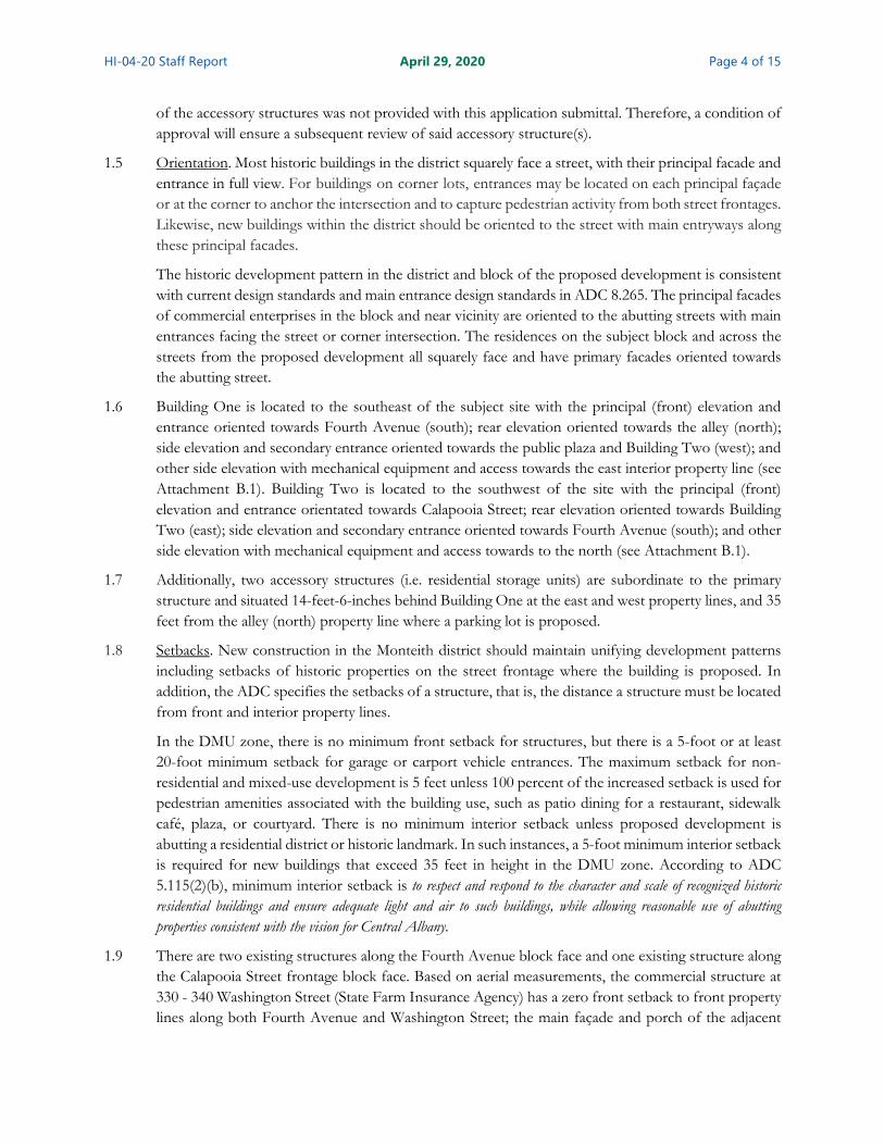
1.6 Building One is located to the southeast of the subject site with the principal (front) elevation and entrance oriented towards Fourth Avenue (south); rear elevation oriented towards the alley (north); side elevation and secondary entrance oriented towards the public plaza and Building Two (west); and other side elevation with mechanical equipment and access towards the east interior property line (see Attachment B.1). Building Two is located to the southwest of the site with the principal (front) elevation and entrance orientated towards Calapooia Street; rear elevation oriented towards Building Two (east); side elevation and secondary entrance oriented towards Fourth Avenue (south); and other side elevation with mechanical equipment and access towards to the north (see Attachment B.1).
1.7 Additionally, two accessory structures (i.e. residential storage units) are subordinate to the primary structure and situated 14-feet-6-inches behind Building One at the east and west property lines, and 35 feet from the alley (north) property line where a parking lot is proposed.
1.8 Setbacks. New construction in the Monteith district should maintain unifying development patterns including setbacks of historic properties on the street frontage where the building is proposed. In addition, the ADC specifies the setbacks of a structure, that is, the distance a structure must be located from front and interior property lines.
In the DMU zone, there is no minimum front setback for structures, but there is a 5-foot or at least 20-foot minimum setback for garage or carport vehicle entrances. The maximum setback for non-residential and mixed-use development is 5 feet unless 100 percent of the increased setback is used for pedestrian amenities associated with the building use, such as patio dining for a restaurant, sidewalk café, plaza, or courtyard. There is no minimum interior setback unless proposed development is abutting a residential district or historic landmark. In such instances, a 5-foot minimum interior setback is required for new buildings that exceed 35 feet in height in the DMU zone. According to ADC 5.115(2)(b), minimum interior setback is to respect and respond to the character and scale of recognized historic residential buildings and ensure adequate light and air to such buildings, while allowing reasonable use of abutting properties consistent with the vision for Central Albany.
1.9 There are two existing structures along the Fourth Avenue block face and one existing structure along the Calapooia Street frontage block face. Based on aerial measurements, the commercial structure at 330 - 340 Washington Street (State Farm Insurance Agency) has a zero front setback to front property lines along both Fourth Avenue and Washington Street; the main façade and porch of the adjacent
HI-04-20 Staff Report April 29, 2020 Page 5 of 15
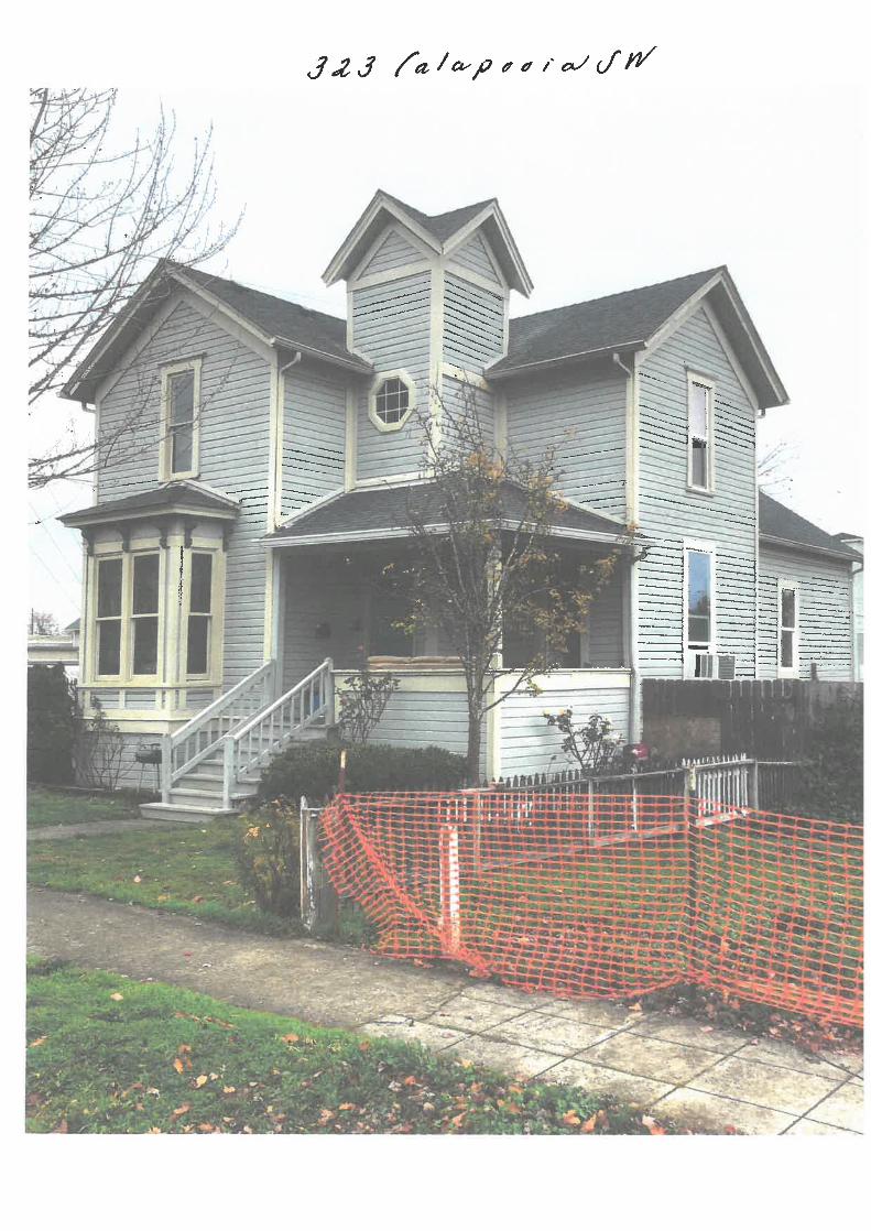
residential dwelling at 515 Fourth Avenue are set back approximately 7 feet and 1 feet respectively from front property along Fourth Avenue; the main façade and porch of the adjacent residential dwelling at 323 Calapooia Street is set back approximately 15 feet from front property along Fourth Avenue (see Attachment A.2).
1.10 Building One has a variable setback of 2-feet to 3-feet-6-inches from the Fourth Avenue (south) front property line; a 6-foot setback from the east interior property line abutting a historic residential dwelling; a 62-feet-5-inch setback from the alley and 23-feet-five-inches setback from the northern interior property line abutting a historic residential dwelling; and a 70-foot setback from the Calapooia Street (west) property line (see Attachment B.1).
Building Two has a variable setback of 2-feet to 3-feet-6-inches from the Calapooia Street (west) front property line and zero setback from the Fourth Avenue front property line; a 6-foot setback from the north interior property line abutting a historic residential dwelling; and a 93-foot setback from the east interior property line abutting a historic residential dwelling (see Attachment B.1).
The residential storage units have zero setback from the east and west interior property lines; a 35-foot setback from the alley (north) property line; and a 60-foot setback from Fourth Avenue (south) front property line (see Attachment B.1).
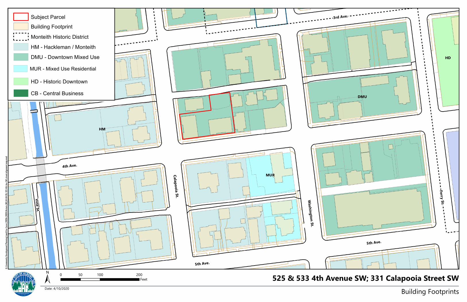
1.11 The approximate footprint of the proposed buildings on the subject property in relationship to structures along the Fourth Avenue and Calapooia Street block face is illustrated in a map entitled Building Footprints (see Attachment A.2). As shown, the proposed building frontages along the Fourth Avenue block face are within the range of setbacks of the two other structures along Fourth Avenue. Conversely, Building Two is approximately 13 feet closer to the front property line along Calapooia Street than the structure at 323 Calapooia Street. A condition of approval shall require Building Two to be no more than five feet closer, and no more than five feet farther from the street than the main wall of the abutting structure at 323 Calapooia Street in order to maintain an unified development pattern along the Calapooia Street block face.
1.12 Building Coverage. The subject property is comprised of two lots (portions of Lots 7 and 8, Block 23, of the City of Albany Subdivision) which are approximately 6,365 square feet and 4,295 square feet in size, respectively. The overall lot size of the proposed development is approximately 10,600 square feet. The total building coverage for the entirety of the development is 51 percent. The building coverage area of Building One and the two accessory structures is approximately 45 percent. The building coverage area of Building Two is approximately 59 percent.
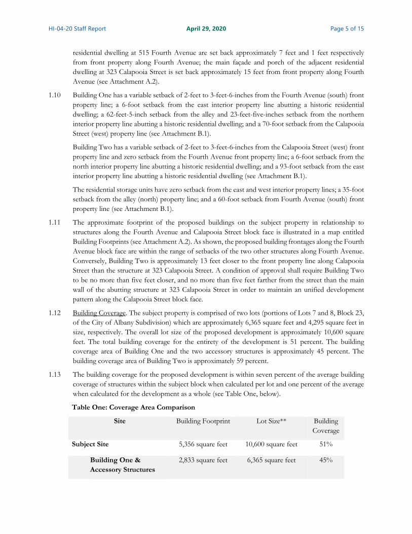
1.13 The building coverage for the proposed development is within seven percent of the average building coverage of structures within the subject block when calculated per lot and one percent of the average when calculated for the development as a whole (see Table One, below).
Table One: Coverage Area Comparison
Site Building Footprint Lot Size** Building Coverage
Subject Site 5,356 square feet 10,600 square feet 51%
Building One & Accessory Structures
2,833 square feet 6,365 square feet 45%

HI-04-20 Staff Report April 29, 2020 Page 6 of 15
Building Two 2,523 square feet 4,295 square feet 59%
323 Calapooia Street 1,355 square feet* 3,159 square feet 43%
306 Washington Street 5,500 square feet* 6,927 square feet 79%
318 Washington Street 830 square feet* 1,698 square feet 48%
320 Washington Street 800 square feet* 1,761 square feet 45%
326 Washington Street 1,150 square feet* 3,332 square feet 35%
520 Third Avenue 3,700 square feet* 6,927 square feet 53%
515 Fourth Avenue 1,215 square feet* 2,062 square feet 58%
* Based on approximate aerial measurements ** Based on Linn County Tax Assessor’s records
1.14 Similarly, a GIS (Geographic Information System Mapping) query of the subject block estimated the average square footage, lot size, and building coverage area on the subject block as 2,361 square feet, 4,248 square feet, and 55 percent, respectively. Based on these analyses, the building coverage of the proposed development is found to be comparable to building coverage of the existing development on the same block.
1.15 Sidewalks. Calapooia Street and Fourth Avenue are classified as local streets and are constructed to City standards along the frontage of the site. Improvements along the frontage of the site include curb, gutter, a six-foot landscape strip, and a five-foot sidewalk on each side of the street.
No modifications to the existing sidewalks are proposed. As shown in the site plan, the following on-site pedestrian improvements are proposed: 1) a paved walkway extension from the interior edge of the existing sidewalk to the front of each building; 2) a concrete public plaza accessible from Fourth Avenue between the buildings; and 3) private internal sidewalks for circulation between buildings, to storage and parking areas, and to the public right-of-way.
1.16 Street Trees. The applicant proposes four street trees at approximately 32-foot intervals in the 6-foot landscape strip along the Fourth Avenue frontage and two street trees 32-feet apart in the planter strip along the Calapooia Street frontage. Presently, there are no street trees within the planter strips along the frontage of the subject property.
There are a few trees planted in the landscaping strip along the street frontages of the block where development is proposed. One street tree is planted along Fourth Avenue southwest of the front entrance of 515 Fourth Avenue. Six street trees are planted along Washington Street near the main entrances of 306 and 326 Washington Street. Four street trees are planted along Third Avenue near the side entrance of 306 Washington Street and parking lot entrances of 530 Third Avenue. Four street trees are planted along Calapooia Street; two street trees are planted along the side of the parking lot at 530 Third Avenue; and two street trees are planted near the front entrance of 323 Calapooia Street. Across the street from the proposed development, there are five street trees along the west side of Calapooia Street and five street trees along the south side of Fourth Avenue.
According to ADC 12.321, street trees are not required unless a new public street is created in conjunction with development. When required, one tree per thirty feet of lineal street frontage is
HI-04-20 Staff Report April 29, 2020 Page 7 of 15
standard. Although not required, the proposed street tree closely align with the spacing interval standard of ADC 12.321 and spacing interval of the existing street trees on the same block.
Conclusions 1.1 A Historic Review of New Construction application for the proposed accessory structures must be
submitted for review and approval prior to the issuance of any building permit for said accessory structure(s).
1.2 The proposed development squarely faces and has primary facades oriented towards the abutting street which is consistent with the historic development pattern in the district.
1.3 The front setbacks of Building One and Two along Fourth Avenue comply with the setback standards of the DMU zone and are within the range of front setbacks along Fourth Avenue block face.
1.4 The front setbacks of Building Two along Calapooia Street comply with the maximum setbacks of the DMU zone but would result in a disorderly development pattern along Calapooia Street block face. A condition of approval will ensure that the front setback of Building Two along the Calapooia Street block face is brought into closer alignment with the structure at 323 Calapooia Street in order to maintain a unified development pattern.
1.5 The building coverage of the proposed development is comparable to building coverage of existing development on the same block.
1.6 The public street system adjacent to the site is constructed to City standards.
1.7 The proposed street tree spacing intervals achieve a uniformed arrangement of street trees along the frontage of the site.
1.8 This criterion can be met with the following conditions.
Conditions of Approval Condition 1 Prior to issuance of a building permit for accessory structure(s), review and approval of a
Historic Review of New Construction application for said proposed accessory structures is required.
Condition 2 Prior to issuance of a building permit for Building Two, the applicant shall submit a revised site plan to the Community Development Department for review and approval that places the front setback of Building Two no more than five feet closer, and no more than five feet farther from the Calapooia Street (front) property line than the main wall of the abutting structure at 323 Calapooia Street SW.
Criterion 2 The structure is of similar size and scale of surrounding buildings, and as much as possible reflects the craftsmanship of those buildings.
Findings of Fact and Conclusions 2.1 Scale and Massing. Building mass and scale includes basic building form characteristics such as width,
size, height, and volume. These design characteristics influence how a building is perceived from the street or sidewalk and how it relates to neighboring development. Although a new building may be larger than adjacent buildings, it should not be monolithic in scale.

HI-04-20 Staff Report April 29, 2020 Page 8 of 15
2.2 Buildings One and Two are each three stories tall, 57-feet-10-inches wide and 43-feet-6-inches deep with a total building area of 6,732 square feet (see Elevation Plans, Attachments B8 & B9).
2.3 In comparison with the abutting historic contributing single-family residential dwellings to the north and east, the proposed structures are approximately twice as wide and seven times as big.
Table Two: Building Size Comparison
Site Building Width Building Depth Area
Subject Site
Building One 57 feet 10 inches wide 45 feet 10 inches deep 6,732 square feet
Building Two 57 feet 10 inches wide 45 feet 10 inches deep 6,732 square feet
323 Calapooia Street 28 feet wide* 44 feet deep* 1,546 square feet**
320 Washington Street 25 feet wide* 30 feet deep* 528 square feet**
515 Fourth Avenue 25 feet wide* 40 feet deep* 900 square feet**
* Based on approximate aerial measurements ** Based on Linn County Tax Assessor’s records
2.4 A combination of articulation techniques is proposed to promote a sense of human scale and reflect traditional façade proportions. Building articulation includes vertical or horizontal changes in materials, color, and texture, as well as minor variations in the wall plane.
2.5 Variations in Material & Wall Projections. The primary facades and entrances of Buildings One and Two are defined by differentiating materials such as cultured stone, brick, aluminum storefront windows and doors, and projecting roof overhangs that are finished with wood beams, brackets, and column trim.
2.6 The secondary facades and entrances of Buildings One and Two are similarly defined by cultured stone, brick, aluminum storefront windows and doors, and projecting powdered coated metal awnings. These projecting powdered coated metal awnings are replicated above the first-story storefront flanking the main entrance doorways.
2.7 There is no articulation on the rear elevations of Buildings One and Two but the five-foot-deep decks that span the length of the upper two floors of the proposed structures provided horizontal articulation. Additionally, variations in the railing finishes (i.e. smooth composite lap railing siding and powder coated metal railing material) creates a visual break and interest along the wall plane.
2.8 Wall offsets. Offset wall planes on the primary facades of Buildings One and Two are also proposed to create visual interest and breaking up the massing of the structures. On the ground and upper levels of the front elevation, slight offsets are used to break up the wall plane into approximately 16.5-foot to 25-foot segments. The depth of the ground floor and upper floor recesses are one-foot-five-inches and two-feet-four-inches, respectively.
The proposed offsets break up the wall plane but are not deep enough to reduce the perceived mass and scale of the building. Offsets between main façade and porches of adjacent residential development in the district are found to be on average five feet deep. Therefore, condition of approval will require
HI-04-20 Staff Report April 29, 2020 Page 9 of 15
a minimum five-foot offset to closely approximate that of adjacent development and to ensure the proper impact of breaking up the massing of the structures.
2.9 Base, Middle, Cap design. The facade of the building is visually divided into three sections where a “base” and “cap” are clearly perceived and the “middle” includes everything in between. The cap includes cross gables, overhanging eaves, eave brackets, and shingles in the roof faces on the primary façade. The middle includes wall plane offsets, symmetrically arranged windows, mid-section trim, and variation in surface treatments. The base is defined by variation in surface treatments, offsets, and projections as previously, described under finding 2.5 and 2.6 above.
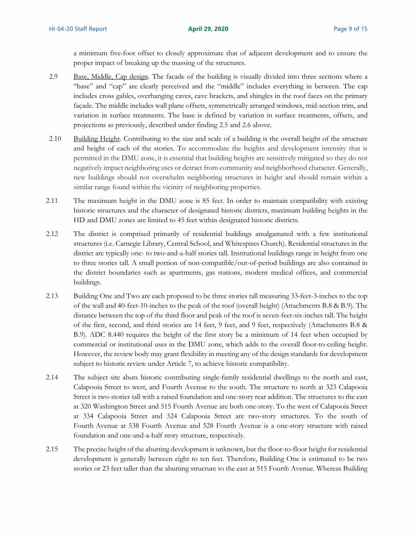
2.10 Building Height. Contributing to the size and scale of a building is the overall height of the structure and height of each of the stories. To accommodate the heights and development intensity that is permitted in the DMU zone, it is essential that building heights are sensitively mitigated so they do not negatively impact neighboring uses or detract from community and neighborhood character. Generally, new buildings should not overwhelm neighboring structures in height and should remain within a similar range found within the vicinity of neighboring properties.
2.11 The maximum height in the DMU zone is 85 feet. In order to maintain compatibility with existing historic structures and the character of designated historic districts, maximum building heights in the HD and DMU zones are limited to 45 feet within designated historic districts.
2.12 The district is comprised primarily of residential buildings amalgamated with a few institutional structures (i.e. Carnegie Library, Central School, and Whitespires Church). Residential structures in the district are typically one- to two-and-a-half stories tall. Institutional buildings range in height from one to three stories tall. A small portion of non-compatible/out-of-period buildings are also contained in the district boundaries such as apartments, gas stations, modern medical offices, and commercial buildings.
2.13 Building One and Two are each proposed to be three stories tall measuring 33-feet-3-inches to the top of the wall and 40-feet-10-inches to the peak of the roof (overall height) (Attachments B.8 & B.9). The distance between the top of the third floor and peak of the roof is seven-feet-six-inches tall. The height of the first, second, and third stories are 14 feet, 9 feet, and 9 feet, respectively (Attachments B.8 & B.9). ADC 8.440 requires the height of the first story be a minimum of 14 feet when occupied by commercial or institutional uses in the DMU zone, which adds to the overall floor-to-ceiling height. However, the review body may grant flexibility in meeting any of the design standards for development subject to historic review under Article 7, to achieve historic compatibility.
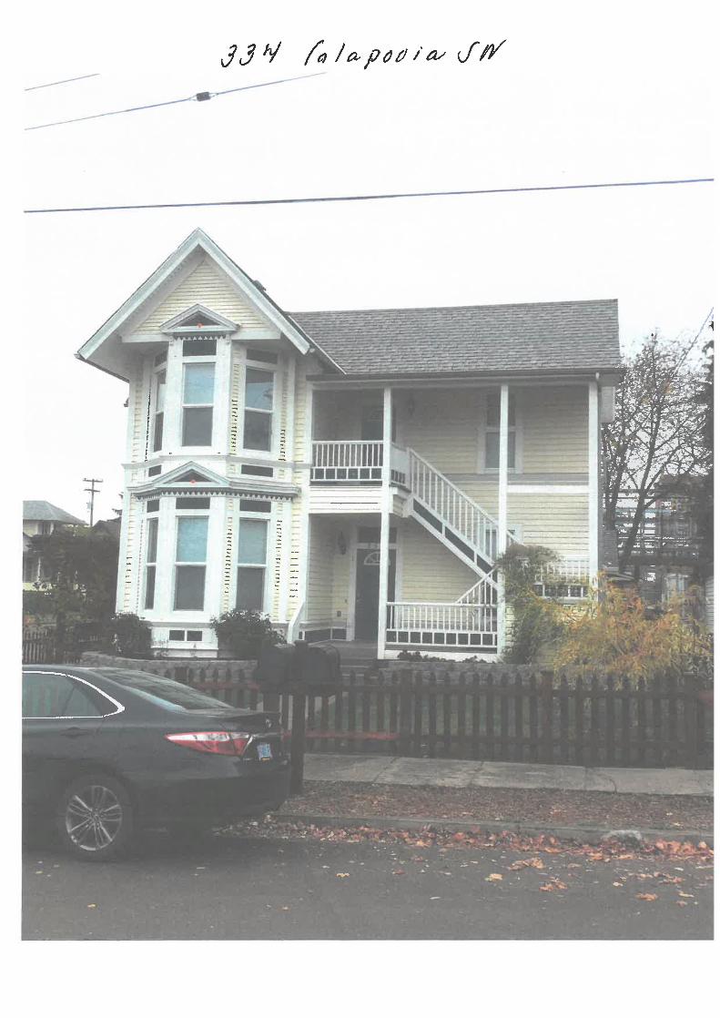
2.14 The subject site abuts historic contributing single-family residential dwellings to the north and east, Calapooia Street to west, and Fourth Avenue to the south. The structure to north at 323 Calapooia Street is two-stories tall with a raised foundation and one-story rear addition. The structures to the east at 320 Washington Street and 515 Fourth Avenue are both one-story. To the west of Calapooia Street at 334 Calapooia Street and 324 Calapooia Street are two-story structures. To the south of Fourth Avenue at 538 Fourth Avenue and 528 Fourth Avenue is a one-story structure with raised foundation and one-and-a-half story structure, respectively.
2.15 The precise height of the abutting development is unknown, but the floor-to-floor height for residential development is generally between eight to ten feet. Therefore, Building One is estimated to be two stories or 23 feet taller than the abutting structure to the east at 515 Fourth Avenue. Whereas Building

HI-04-20 Staff Report April 29, 2020 Page 10 of 15
Two is estimated to be one-story or ten feet taller than the abutting structure to the north at 323 Calapooia Street.
2.16 A reduction to the overall and first-floor wall height of Building One and Two is required to maintain and respect the height of abutting residential dwellings, particularly to the east of the subject site. A minimum four-foot reduction to the overall height including a minimum two-foot reduction to the first-floor wall height is required to reduce the disparity in height and horizontal floor alignment between the proposed and existing abutting development.
2.17 Roof Form. In the district, the predominant roof shape is a traditional gable and hipped roof, with a few mansard and gambrel roofs. Bungalows typically have gable roofs with pitches of at least 4:12, and other architectural styles typically have a roof pitch of 8:12 or greater. Most commercial, mixed use, and multi-family buildings in the districts have flat roofs.
2.18 The roof shapes of Buildings One and Two include a main side gable with two cross gables at the front and rear main entrances and wall gables on either side of the front cross gable. The roof pitch of the main side gable is 4:12. The roof pitch of the cross gables and wall gables is 6:12. The proposed shape and pitch are comparable to the predominant residential style roof shapes and pitch within the district.
2.19 Craftsmanship. Architectural details proposed should be consistent with the architectural styles found within the district. Architectural details that are more ornate or elaborate than those found within the district are inappropriate.
The proposed structures incorporate the following architectural elements typical of Craftsman style buildings: overhanging eaves, eave brackets, shingles in the roof faces, wood porch columns with brackets, and lap siding, which are reflective of architectural details found throughout the district.
Conclusions 2.1 The proposed structures are approximately twice as wide and seven times as big as abutting single-
family development. However, the mass and scale of the proposed structures is visibility reduced by building articulation and vertical or horizontal changes in finish materials, color, and texture.
2.2 Offsets also are used to break up the wall plane but are not deep enough to reduce the perceived mass and scale of the building. A condition of approval will require deeper offsets to approximate that of adjacent development and to ensure the proper impact of breaking up the perceived massing and scale of the structures.
2.3 Building Two is one story taller than the abutting structure to the north and Building One is two stories taller than the abutting structure to the east. A condition of approval will ensure that the overall height of Building One and Two is reduced including a reduction to the first-floor wall height to reduce the disparity in height and horizontal floor alignment between the proposed and existing abutting development.
2.4 The building style and combination of building elements proposed is consistent with the craftsmanship of the other houses in the surrounding area and district.
2.5 This criterion can be met with the following conditions.

HI-04-20 Staff Report April 29, 2020 Page 11 of 15
Conditions
Condition 3 Prior to issuance of a building permit, the applicant shall submit a revised elevation plan(s) and/or floor plans to the Community Development Department for review and approval that show a minimum five-foot-deep offsets in the same locations as proposed (i.e. primary street facing facades) of Buildings One and Two.
Condition 4 Prior to issuance of a building permit, the applicant shall submit a revised elevation plan(s) to the Community Development Department for review and approval that shows the height of Buildings One and Two reduced a minimum of four feet overall including a minimum two-foot reduction to the first-floor wall height.
Criterion 3 Building materials are reflective of and complementary to existing buildings within the district.
Findings of Fact and Conclusions 3.1 Much of the character of a building resides with the variety and composition of architectural details
and building materials. The materials used for walls, windows, sloping roofs, details, and other visible elements of historic buildings should be respected in the design of a new building. In districts where the existing buildings use diverse exterior materials, a range of exterior materials may be used by a compatible new building.
3.2 The size, texture, surface finish, and other defining characteristics of exterior materials are as important as the type of material itself. Building materials should complement the size, texture, surface finish, and other defining characteristics of exterior materials traditionally found in the district.
3.3 Detailed window information such as functionality (fixed/operable), grid type (between the glass, exterior, or simulated divided lites), and obscuring (textured/frosted/etc.) is not provided in the application submittal. Operable windows appear to be primarily horizonal slide except for the (bathroom) windows on the side elevations and windows next to the rear doorway that are single or double-hung. Single horizontal slide windows are not consistent with traditional single-hung or double-hung vertical window styles found in the vicinity and surrounding district.
3.4 Street Facing Windows - Upper Levels. On the primary elevations, the proposed second and third floor windows are symmetrically arranged and uniform in style and dimensions. Each window is six-foot-wide by four-and one-half foot-tall with six-over-three grid pattern and composite frames.
3.5 Street Facing Windows - Ground Level: On the primary street facing elevations, the first-floor windows and doors are symmetrically arranged and uniform in style and dimensions. The first floor includes two arched topped fixed storefront windows flanking the primary entrance. However, most transom windows over storefront windows are rectangular and multi-paned like what is proposed over the main entrances. The primary entrance includes two side-by-side entry doors each flanked with side lites and square overhead transom. All first-floor storefront windows appear to be fixed with aluminum frames.
3.6 Side Elevation Windows: On the side elevations, a variety of window types (i.e. multi-paned, sliders, one-over-one) are incorporated, which provides inconsistency in architectural style and detail. This is

HI-04-20 Staff Report April 29, 2020 Page 12 of 15
especially noticeable on the side street facing elevation of Building Two, where windows vary in functionality, size, style, and arrangement.
3.7 Rear Elevation Windows: On the rear elevations, the applicant proposes composite framed windows. The second and third story windows on the rear elevation are not symmetrical with windows on the ground floor nor the same function and size per floor. Additionally, the window function (i.e. sliders, one-over-one) and sizes also differ between the ground floor to upper floors.
3.8 Window Trim. Apart from the storefront windows, most of the windows are shown trimmed with approximately five-inch-wide wood trim that appears to include a true projecting sill and top molding. Windows lacking trim, sills, and top molding can be found on the plaza elevation (west) of Building One and street facing elevation (south) of Building Two as well as the interior side elevations (east, Building One and north, Building Two).
3.9 Doors. The storefront doors on the primary street facing elevations, are seven-feet-tall, full lite, aluminum framed. Exterior doors on the rear elevations vary in size and design. The styles proposed include: 1) four raised paneled; 2) half lite commercial entryways; 3) solid maintenance/storage entryways. The door material type is unknown.
3.10 Door Trim. Similar to the windows, the doors are shown to be trimmed with wood trim that appears to be approximately five-inches-wide and include top molding.
3.11 Siding. A variety of surface treatments are proposed. The predominant surface treatment is smooth, horizontal, seven-inch-wide, cement-fiber lap siding (Attachments B8 & B9). Smooth, cement-fiber straight shingles are proposed for the gables and to either side of the main front wall. Masonry treatments (i.e. cultured stone and brick) are proposed to accent storefront windows on either side of the primary entrance and columns bases. Information regarding the profile of the face of the siding as well as the finish of the masonry accents was not included in the application submittal.
3.12 Roofing. Architectural composite shingles are proposed as the roof covering material. Architectural shingles are constructed with multiple layers of material that gives the “dimensional” shingles a layered or three-dimensional look. Architectural composite shingles are common in the district and can be found on all abutting properties.
3.13 Awnings. Powder coated metal awnings are proposed to project over the side building entrances and over windows one either side of the main entrance doorways.
3.14 Wood Beams, Brackets and Column Trim. Solid wood architectural beams, brackets, and columns are shown on the Elevation Plans (see Attachments B8 & B9).
Conclusions 3.1 The proposed contemporary materials not traditionally used in the district, such as brick, simulated
stone veneer, composite window frames, and fiberboard siding, are appropriate for new construction in the district when materials are visually similar to the traditional material in dimension, finish, and texture.
3.2 The first floor includes two arched topped fixed storefront windows flanking the primary entrance. A condition of approval will require rectangular and multi-paned transom windows over storefront windows like what is proposed over the main entrances.
HI-04-20 Staff Report April 29, 2020 Page 13 of 15
3.3 A variety of window types (i.e. multi-paned, sliders, one-over-one), sizes, and alignment are incorporated. A condition of approval will ensure consistency in the function, size, and style of windows.
3.4 Most but not all windows are shown trimmed with wood trim that includes a true projecting sill and top molding that is approximately five inches wide. A condition of approval will ensure all composite framed windows are trimmed the same. Storefront windows are not required to be trimmed as they are accented by masonry finishes.
3.5 Exterior doors on the rear elevation vary in style, size, and design. The material type of the doors is unknown. A condition of approval will ensure uniformity in the material and style of all doors, except the storefront doors, which are to be full lite with aluminum frames.
3.6 Architectural beams, brackets, and columns are to be solid wood.
3.7 This criterion can be met with the following conditions.
Conditions
Condition 5 Prior to issuance of a building permit, the applicant shall submit revised plan(s) and/or window and door schedules to the Community Development Department for review and approval that illustrates and/or describes the following: 1) all first-floor storefront windows as fixed with aluminum frames and clear/untextured obscuring; 2) all transoms to be rectangular and multi-paned; 3) all windows other than storefront and transoms must be uniformly sized and spaced, single- or double-hung, with either between the glass, or simulated divided grids, and clear/untextured obscuring; 4) all doors to be the same style (i.e. four raised paneled or half lite) and constructed of fiberglass, wood, or steel. Prior to the issuance of an occupancy permit, all doors and windows must be installed as proposed and/or approved.
Condition 6 Prior to issuance of a building permit, the applicant shall submit revised plan(s) to the Community Development Department for review and approval that illustrates and/or describes all composite window frames trimmed with solid wood and include a true projecting sill and top wood molding that is at least five inches wide. Prior to the issuance of a certificate of occupancy, all composite window frames must be installed as proposed and/or approved.
Condition 7 Prior to issuance of a building permit, the applicant shall submit revised plan(s) to the Community Development Department for review and approval that illustrates and/or describes the profile of the siding as well as the finish of the masonry accents. All siding is to be smooth without faux grain. Prior to the issuance of an occupancy permit, all siding and masonry accents are to be installed as proposed and/or approved.
Condition 8 Prior to issuance of a building permit, the applicant shall submit revised plan(s) to the Community Development Department for review and approval that illustrates and/or describes architectural beams, brackets, and columns as solid wood. Prior to the issuance of a certificate of occupancy, all solid wood beams, brackets, and columns must be installed as proposed and/or approved.

HI-04-20 Staff Report April 29, 2020 Page 14 of 15
Overall Conclusion – Conditions of Approval As proposed and conditioned, the application for Historic Review of New Construction application of two three-story mixed-use buildings on a lot within the Monteith National Register Historic District satisfies all applicable review criteria as outlined in this report.
Condition 1 Prior to issuance of a building permit for accessory structure(s), review and approval of a Historic Review of New Construction application for said proposed accessory structures shall be required.
Condition 2 Prior to issuance of a building permit for Building Two, the applicant shall submit a revised site plan to the Community Development Department for review and approval that places the front setback of Building Two no more than five feet closer and no more than five feet farther from the main wall of the abutting structure at 323 Calapooia Street SW, along the Calapooia Street (front) property line.
Condition 3 Prior to issuance of a building permit, the applicant shall submit a revised elevation plan(s) and/or floor plans to the Community Development Department for review and approval that show a minimum five-foot deep offsets in the same locations as proposed (i.e. primary street facing facades) of Building One and Two.
Condition 4 Prior to issuance of a building permit, the applicant shall submit a revised elevation plan(s) to the Community Development Department for review and approval that shows the height of Building One and Two reduced a minimum of four feet overall including a minimum two-foot reduction to the first-floor wall height.
Condition 5 Prior to issuance of a building permit, the applicant shall submit revised plan(s) and/or window and door schedules to the Community Development Department for review and approval that illustrates and/or describes the following: 1) all first-floor storefront windows as fixed with aluminum frames and clear/untextured obscuring; 2) all transoms to be rectangular and multi-paned; 3) all windows other than storefront and transoms to be uniformly sized and spaced, single- or double-hung, with either between the glass, or simulated divided grids, and clear/untextured obscuring; 4) all doors to be the same style (i.e. four raised paneled or half lite) and constructed of fiberglass, wood, or steel. Prior to the issuance of an occupancy permit, all doors and windows must be installed as proposed and/or approved.
Condition 6 Prior to issuance of a building permit, the applicant shall submit revised plan(s) to the Community Development Department for review and approval that illustrates and/or describes all composite window frames trimmed with solid wood and include a true projecting sill and top molding that is at least five inches wide. Prior to the issuance of a certificate of occupancy, all composite window frames must be installed as proposed and/or approved.
Condition 7 Prior to issuance of a building permit, the applicant shall submit revised plan(s) to the Community Development Department for review and approval that illustrates and/or describes the profile of the siding as well as the finish of the masonry accents. All siding is to be smooth without faux grain. Prior to the issuance of an occupancy permit, all siding and masonry accents are to be installed as proposed and/or approved.

HI-04-20 Staff Report April 29, 2020 Page 15 of 15
Condition 8 Prior to issuance of a building permit, the applicant shall submit revised plan(s) to the Community Development Department for review and approval that illustrates and/or describes architectural beams, brackets, and columns as solid wood. Prior to the issuance of a certificate of occupancy, all solid wood beams, brackets and columns must be installed as proposed and/or approved.
Options and Recommendations The Landmarks Commission has three options with respect to the subject application:
Option 1: Approve the request as proposed; or
Option 2: Approve the request with conditions of approval; or
Option 3: Deny the request.
Based on the discussion above, staff recommends that the Landmarks Commission pursue Option 2 and approve the application subject to the conditions of approval. If the Landmarks Commission accepts this recommendation, the following motion is suggested.
Suggested Motion I move to approve the proposed New Construction application planning file HI-04-20 as conditioned in this staff report. This motion is based on the findings and conclusions in the April 29, 2020, staff report and the findings in support of the application made by the Landmarks Commission during deliberations on this matter.
Attachments A. Staff Provided Reference Material
1. Location Map 2. Building Footprint Map 3. Guidelines for New Construction in Albany’s Residential Historic Districts & Neighborhoods
B. Applicant’s Plan Set 1. Site Plan (A0.1) 2. Pre-Existing Site Plan (A0.2) 3. Utility Plan (A0.3) 4. Ground Floor Plan (A1.1) 5. Second Floor Plan (A1.2) 6. Third Floor Plan (A1.3) 7. Roof Plan (A1.4) 8. Elevation Plan (A3.0) 9. Elevation Plan (A3.1) 10. Finding of Facts
Acronyms ADC Albany Development Code DMU Downtown Mixed-Use Zone District HI Historic Review File Designation HM Hackleman Monteith Zone District LC Landmarks Commission


±
G:\Com
munity
Devel
opment
\Planni
ng\Lan
d Use C
ases\2
020s\2
020\Hi
storic
(HI)\HI
-04-20
; 525 4
th Ave
SW\zo
ne.dist
rict.ma
p.mxd
0 250 500125Feet
Date: 4/16/2020 Map Source: City of Albany
525 & 533 4th Avenue SW331 Calapooia Street SW
Location / Zoning Map
HD
DMU
HM
OS
OP
MUR
1st Ave.
Washington St.
2nd Ave.
3rd Ave.
5th Ave.
Ferry St.
6th Ave.
4th Ave.
Calapooia St.
3rd Ave.
5th Ave.
Vine St.
7th Ave.
Broadalbin St.1st Ave.
2nd Ave.
Washington St.
Vine St.
Broadalbin St.
Calap
ooia
River
HM - Hackleman / Monteith
LE - Lyon / EllsworthHD - Historic Downtown
DMU - Downtown Mixed UseMUR - Mixed Use ResidentialMonteith Historic DistrictDowntown Historic DistrictSubject Site
HM - Hackleman / Monteith
LE - Lyon / EllsworthHD - Historic Downtown
DMU - Downtown Mixed Use

±
G:\Com
munity
Devel
opment
\Planni
ng\Lan
d Use
Cases\
2020s\
2020\H
istoric
(HI)\HI
-04-20
; 525 4
th Ave
SW\str
eet.ali
gnment
.map.m
xd
Building Footprints
0 100 20050Feet
Date: 4/10/2020
525 & 533 4th Avenue SW; 331 Calapooia Street SW
HM
DMU
HD
MUR
3rd Ave.
Washington St.
Bryant Way
5th Ave.
4th Ave.
Ferry St.
Calapooia St.
5th Ave.
3rd Ave.
Vine St.Vine St.
Calap
ooia
River Subject Parcel
Building FootprintMonteith Historic District
MUR - Mixed Use Residential
CB - Central Business
DMU - Downtown Mixed UseHM - Hackleman / Monteith
HD - Historic Downtown


1
Guidelines for New Construction in Albany’s Residential Historic Districts &
Neighborhoods
Examples of new construction that fit into the historic neighborhood.

New Construction in Historic Districts & Neighborhoods
2
Albany’s historic residential neighborhoods developed over many decades, and contain houses of many different styles, shapes and sizes. Because of this, there is no single blueprint for a new house that will be compatible with any given historic neighborhood. However, the architectural character and details found on Albany’s historic buildings provide the “architectural vocabulary” that can be used in designing new buildings that are compatible with Albany’s historic neighborhoods. The careful, sensitive and thoughtful design of any new construction in the districts is of the utmost importance because it must harmonize with the character of the neighborhoods and be made compatible with existing historic structures.
PURPOSE OF NEW CONSTRUCTION GUIDELINES
The purpose of these guidelines is to help property owners and contractors choose an appropriate approach when building in a historic district so that projects satisfy the standards and review criteria in the Albany Development Code (Article 7, Historic Overlay Districts). These guidelines are also intended to help property owners and others understand the special features and characteristics of Albany’s historic structures and incorporate that understanding into designs for new construction. Objectives of the Guidelines:
• Help projects meet the review criteria and Secretary of Interiors Standards in the Albany Development Code.
• Maintain the integrity of our historic buildings and neighborhoods. Protect the existing historic buildings in the districts.
HISTORIC REVIEW To protect the integrity of the Albany’s historic resource, the City of Albany adopted the preservation ordinance in 1985. It requires all buildings built before 1946 in the National Register Historic Districts and those included on the City's official Local Historic Inventory to get historic approval for new buildings over 100 square feet. DEVELOPMENT CODE REVIEW CRITERIA 7.270 New Construction Review Criteria. The Community Development Director or the Landmarks
Advisory Commission must find that the request meets the following applicable criteria in order to approve the new construction request:
(1) Within the Monteith and Hackleman Districts:
(a) The development maintains any unifying development patterns such as sidewalk and street tree location, setbacks, building coverage, and orientation to the street.
(b) The structure is of similar size and scale of surrounding buildings, and as much as possible reflects the craftsmanship of those buildings.
(c) Building materials are reflective of and complementary to existing buildings within the district.
New Construction in Historic Districts & Neighborhoods
3
WHAT MAKES A NEW BUILDING “COMPATIBLE” IN A HISTORIC NEIGHBORHOOD?
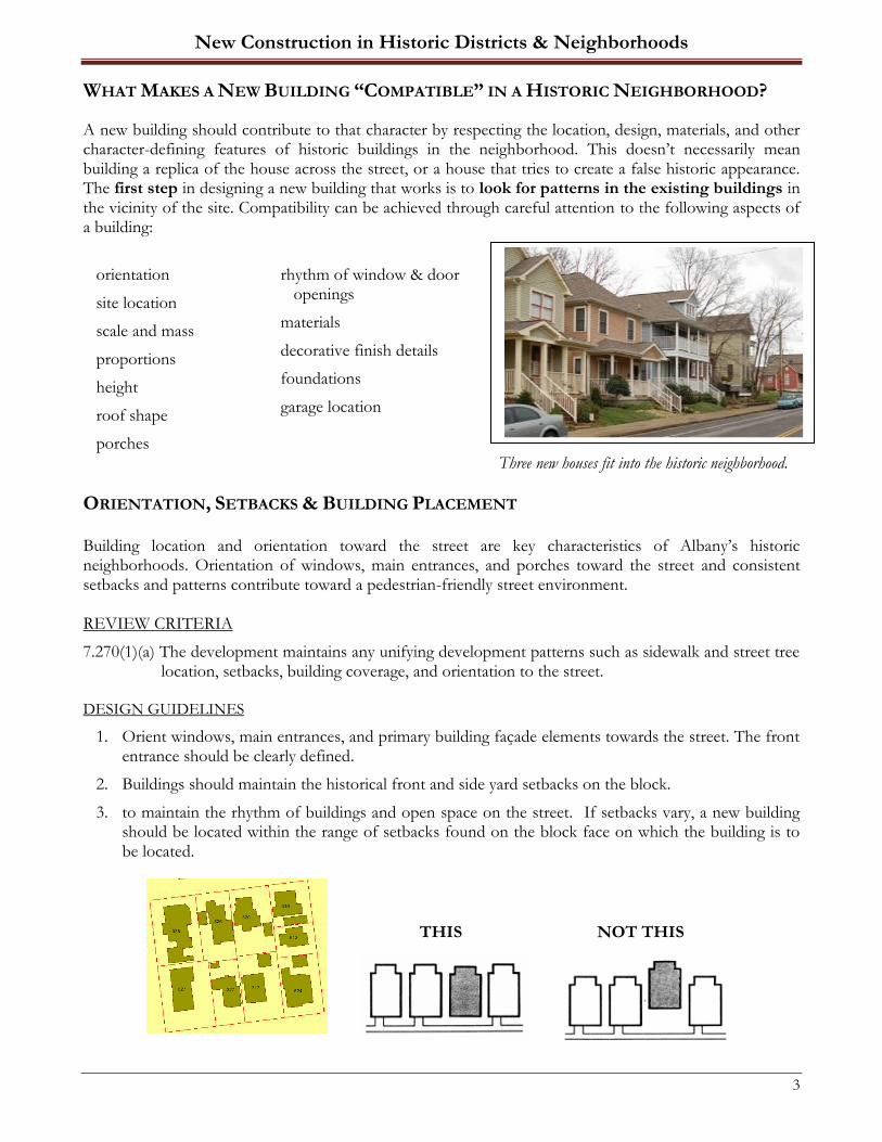
A new building should contribute to that character by respecting the location, design, materials, and other character-defining features of historic buildings in the neighborhood. This doesn’t necessarily mean building a replica of the house across the street, or a house that tries to create a false historic appearance. The first step in designing a new building that works is to look for patterns in the existing buildings in the vicinity of the site. Compatibility can be achieved through careful attention to the following aspects of a building:
orientation
site location
scale and mass
proportions
height
roof shape
porches
rhythm of window & door openings
materials
decorative finish details
foundations
garage location
Three new houses fit into the historic neighborhood.
ORIENTATION, SETBACKS & BUILDING PLACEMENT Building location and orientation toward the street are key characteristics of Albany’s historic neighborhoods. Orientation of windows, main entrances, and porches toward the street and consistent setbacks and patterns contribute toward a pedestrian-friendly street environment. REVIEW CRITERIA
7.270(1)(a) The development maintains any unifying development patterns such as sidewalk and street tree location, setbacks, building coverage, and orientation to the street.
DESIGN GUIDELINES
1. Orient windows, main entrances, and primary building façade elements towards the street. The front entrance should be clearly defined.
2. Buildings should maintain the historical front and side yard setbacks on the block.
3. to maintain the rhythm of buildings and open space on the street. If setbacks vary, a new building should be located within the range of setbacks found on the block face on which the building is to be located.
THIS NOT THIS
New Construction in Historic Districts & Neighborhoods
4
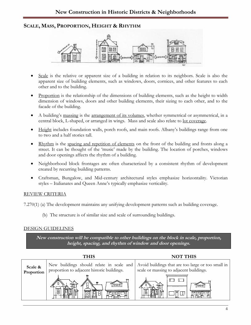
SCALE, MASS, PROPORTION, HEIGHT & RHYTHM
• Scale is the relative or apparent size of a building in relation to its neighbors. Scale is also the apparent size of building elements, such as windows, doors, cornices, and other features to each other and to the building.
• Proportion is the relationship of the dimensions of building elements, such as the height to width dimension of windows, doors and other building elements, their sizing to each other, and to the facade of the building.
• A building’s massing is the arrangement of its volumes, whether symmetrical or asymmetrical, in a central block, L-shaped, or arranged in wings. Mass and scale also relate to lot coverage.
• Height includes foundation walls, porch roofs, and main roofs. Albany’s buildings range from one to two and a half stories tall.
• Rhythm is the spacing and repetition of elements on the front of the building and fronts along a street. It can be thought of the ‘music’ made by the building. The location of porches, windows and door openings affects the rhythm of a building.
• Neighborhood block frontages are often characterized by a consistent rhythm of development created by recurring building patterns.
• Craftsman, Bungalow, and Mid-century architectural styles emphasize horizontality. Victorian styles – Italianates and Queen Anne’s typically emphasize verticality.
REVIEW CRITERIA
7.270(1) (a) The development maintains any unifying development patterns such as building coverage.
(b) The structure is of similar size and scale of surrounding buildings.
DESIGN GUIDELINES
THIS NOT THIS
Scale & Proportion
New buildings should relate in scale and proportion to adjacent historic buildings.
Avoid buildings that are too large or too small in scale or massing to adjacent buildings.
New construction will be compatible to other buildings on the block in scale, proportion, height, spacing, and rhythm of window and door openings.

New Construction in Historic Districts & Neighborhoods
5
THIS NOT THIS
Scale & Proportion
New buildings should relate in scale and proportion to adjacent historic buildings.
Avoid buildings that are too large or too small in scale or massing to adjacent buildings.
Mass Break up boxlike forms into smaller, varied masses using porches, windows, roof forms
common on historic buildings.
Avoid single, monolithic forms that are not relieved by variations in mass.
Height Building height should be within the range of heights of area buildings. Step larger buildings
down to smaller buildings.
Avoid construction that greatly varies in height from buildings in the same block.
Rhythm Window and door openings should be
located to create a pattern similar to those found on historic homes. Continue
established building rhythms along the street.
Avoid “odd” window and door shapes and sizes and lack of rhythm in their placement.
This new house uses appropriate detailing, scale, & rhythm.
New Construction in Historic Districts & Neighborhoods
6
CRAFTSMANSHIP A lack of attention to the character of the design, the materials and details, and to the context within which the building will be placed can have a significant adverse impact for the area that can last a long time. The craftsmanship and architectural details are critical to making a new building be consistent with the character of the historic neighborhood. Several areas of the building design offer opportunities to incorporate appropriate levels of craftsmanship into a new building.
REVIEW CRITERIA
7.270(1)(b) The structure … as much as possible reflects the craftsmanship of those buildings. Building materials are reflective of and complementary to existing buildings within the district.
A. ROOFS Roof shapes, patterns and colors are important to the character of buildings, both individually and as they are repeated along a streetscape. DESIGN GUIDELINES
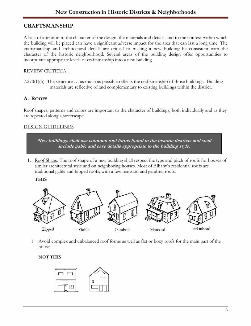
1. Roof Shape. The roof shape of a new building shall respect the type and pitch of roofs for houses of similar architectural style and on neighboring houses. Most of Albany’s residential roofs are traditional gable and hipped roofs; with a few mansard and gambrel roofs.
THIS
1. Avoid complex and unbalanced roof forms as well as flat or boxy roofs for the main part of the house.
NOT THIS
New buildings shall use common roof forms found in the historic districts and shall include gable and eave details appropriate to the building style.
New Construction in Historic Districts & Neighborhoods
7
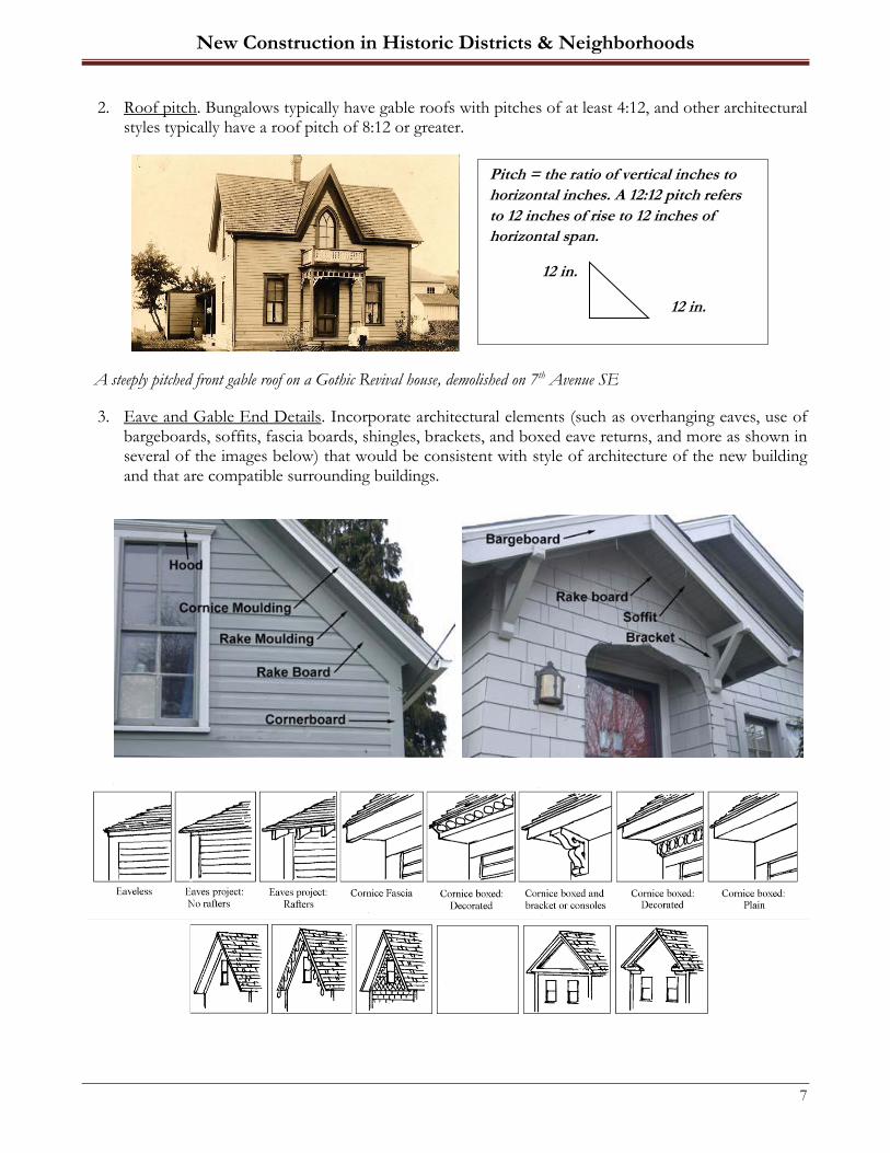
2. Roof pitch. Bungalows typically have gable roofs with pitches of at least 4:12, and other architectural styles typically have a roof pitch of 8:12 or greater.
A steeply pitched front gable roof on a Gothic Revival house, demolished on 7th Avenue SE
3. Eave and Gable End Details. Incorporate architectural elements (such as overhanging eaves, use of bargeboards, soffits, fascia boards, shingles, brackets, and boxed eave returns, and more as shown in several of the images below) that would be consistent with style of architecture of the new building and that are compatible surrounding buildings.
Pitch = the ratio of vertical inches to
horizontal inches. A 12:12 pitch refers
to 12 inches of rise to 12 inches of
horizontal span.
12 in.
12 in.

New Construction in Historic Districts & Neighborhoods
8
4. Dormers. Dormers provide additional use and light for upper levels and can further define and enrich the building architecture. If used, dormers should be modest in size and fit the scale of the house and the roof.
B. PORCHES & ENTRIES
The front porch or covered entrance is a characteristic feature of many styles of historic residential architecture and plays a very important role in our buildings.
Pre 1900: Typical chamfered columns, simple balustrade Post 1900: Wide tapered columns on a porch wall. and newel posts. 431 8th Avenue SW
New Construction in Historic Districts & Neighborhoods
9
DESIGN GUIDELINES
1. Porches, covered or recessed entries shall be included on new houses. Porches typically cover the entrance, and usually extend partially or fully across the main façade.
2. Porch columns and railings should be simple in design in square or round shapes. If balusters are used, they should be no more than two inches square or in diameter.
3. Columns should be a minimum of six inches and a maximum of ten inches square or in diameter.
4. Bungalows frequently featured boxed-in porch railings, though historic railings were not as high as the building code currently requires.
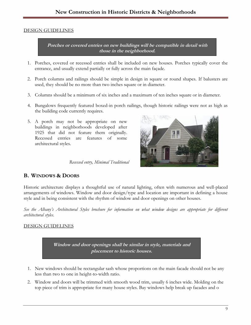
5. A porch may not be appropriate on new buildings in neighborhoods developed after 1925 that did not feature them originally. Recessed entries are features of some architectural styles.
Recessed entry, Minimal Traditional
B. WINDOWS & DOORS Historic architecture displays a thoughtful use of natural lighting, often with numerous and well-placed arrangements of windows. Window and door design/type and location are important in defining a house style and in being consistent with the rhythm of window and door openings on other houses. See the Albany’s Architectural Styles brochure for information on what window designs are appropriate for different architectural styles. DESIGN GUIDELINES
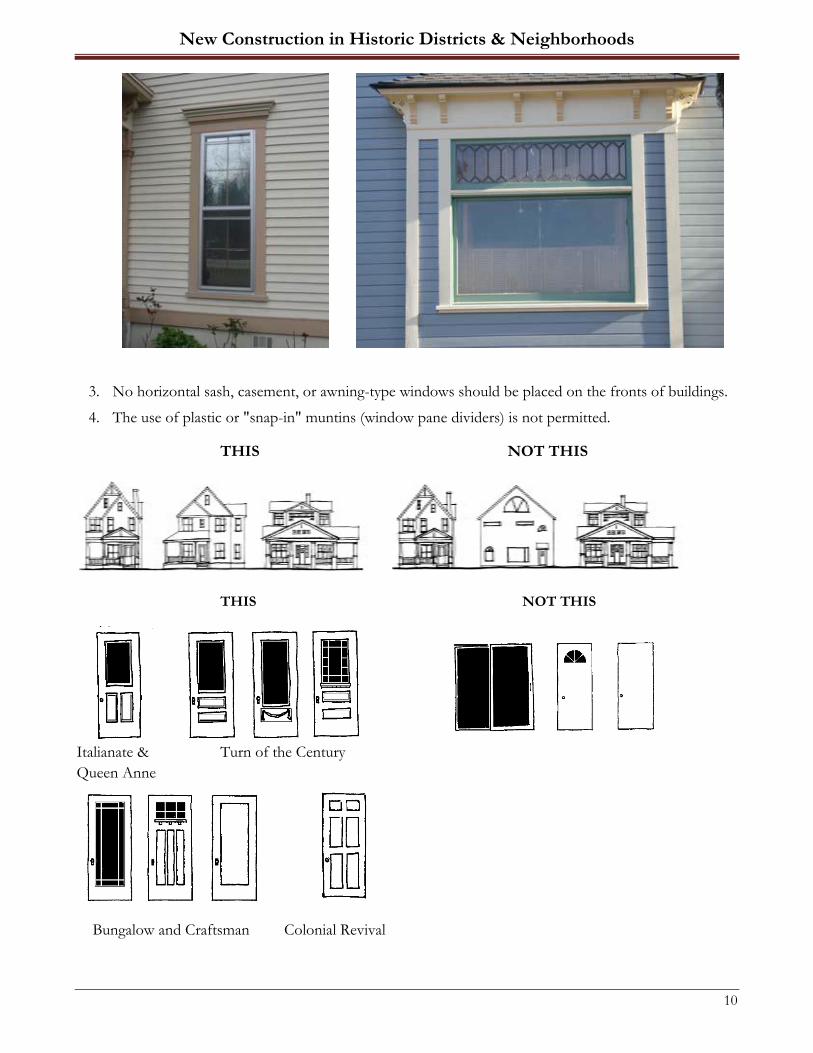
1. New windows should be rectangular sash whose proportions on the main facade should not be any less than two to one in height-to-width ratio.
2. Window and doors will be trimmed with smooth wood trim, usually 6 inches wide. Molding on the top piece of trim is appropriate for many house styles. Bay windows help break up facades and o
Porches or covered entries on new buildings will be compatible in detail with those in the neighborhood.
Window and door openings shall be similar in style, materials and
placement to historic houses.
New Construction in Historic Districts & Neighborhoods
10
3. No horizontal sash, casement, or awning-type windows should be placed on the fronts of buildings.
4. The use of plastic or "snap-in" muntins (window pane dividers) is not permitted.
THIS NOT THIS
THIS NOT THIS
Italianate & Turn of the Century
Queen Anne
Bungalow and Craftsman Colonial Revival

New Construction in Historic Districts & Neighborhoods
11
C. EXTERIOR FINISHES & MATERIALS The size, texture, surface finish and other defining characteristics of exterior materials are as important as the type of material itself. The predominant materials in Albany’s historic neighborhoods are wood - for siding, windows, trim and decorative details, although some housing from the 1920s and 1930s feature brick or stucco exterior walls. Incorporate details that are compatible to the neighborhood and the style of building that is planned to be built. REVIEW CRITERIA
7.270(1)(b) Building materials are reflective of and complementary to existing buildings within the district.
DESIGN GUIDELINES
1. Select a particular style that is appropriate for the building use and size. Maintain stylistic consistency in the design of the building; some variety is typical.
2. Use the same level of architectural details found on historic buildings, including eave details, such as whether rafter tails are exposed or boxed-in, the use of a rake and/or barge boards, shingle moldings, and wide window surrounds.
3. Using similar wall materials – such as lap (bevel, clapboard) or drop (channel, v-notch, shiplap) siding.
4. Using moldings and other decorative details that are generally similar, but somewhat simplified or otherwise distinguishable from the originals.
Materials and finishes used on new buildings should be consistent with the predominant materials used on other houses in a neighborhood.
V- NOTCH
New Construction in Historic Districts & Neighborhoods
12
5. Fabricated wood siding such as T-1-11, along with exposed concrete block, aluminum, and vinyl are not recommended.
6. Foundation material and the height of the exposed area between the ground and the bottom of the walls should be consistent with other historic buildings in a neighborhood.
7. Poured concrete and concrete block covered with stucco are generally appropriate.
8. Exposure of one to three feet is generally consistent with most historical housing types in Albany.
New Construction in Historic Districts & Neighborhoods
13
GARAGE AND OUTBUILDING LOCATION, SIDEWALKS AND DRIVEWAYS Garages and outbuildings must not be overlooked as important components of historic properties. They, too, must fit into the historic neighborhood. GARAGE AND OUTBUILDING DETAILS
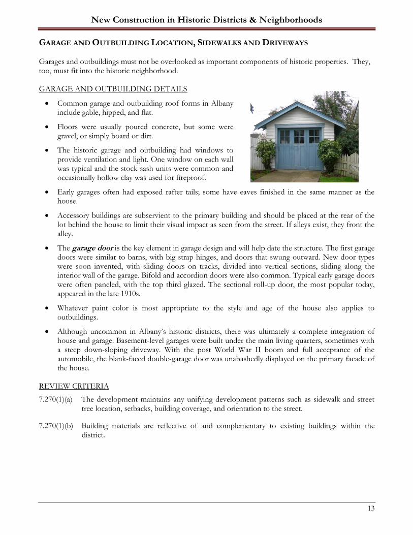
• Common garage and outbuilding roof forms in Albany include gable, hipped, and flat.
• Floors were usually poured concrete, but some were gravel, or simply board or dirt.
• The historic garage and outbuilding had windows to provide ventilation and light. One window on each wall was typical and the stock sash units were common and occasionally hollow clay was used for fireproof.
• Early garages often had exposed rafter tails; some have eaves finished in the same manner as the house.
• Accessory buildings are subservient to the primary building and should be placed at the rear of the lot behind the house to limit their visual impact as seen from the street. If alleys exist, they front the alley.
• The garage door is the key element in garage design and will help date the structure. The first garage doors were similar to barns, with big strap hinges, and doors that swung outward. New door types were soon invented, with sliding doors on tracks, divided into vertical sections, sliding along the interior wall of the garage. Bifold and accordion doors were also common. Typical early garage doors were often paneled, with the top third glazed. The sectional roll-up door, the most popular today, appeared in the late 1910s.
• Whatever paint color is most appropriate to the style and age of the house also applies to outbuildings.
• Although uncommon in Albany’s historic districts, there was ultimately a complete integration of house and garage. Basement-level garages were built under the main living quarters, sometimes with a steep down-sloping driveway. With the post World War II boom and full acceptance of the automobile, the blank-faced double-garage door was unabashedly displayed on the primary facade of the house.
REVIEW CRITERIA
7.270(1)(a) The development maintains any unifying development patterns such as sidewalk and street tree location, setbacks, building coverage, and orientation to the street.
7.270(1)(b) Building materials are reflective of and complementary to existing buildings within the district.
New Construction in Historic Districts & Neighborhoods
14
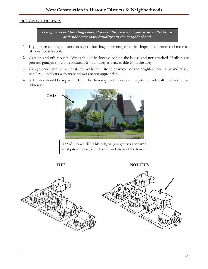
DESIGN GUIDELINES
1. If you’re rebuilding a historic garage or building a new one, echo the shape, pitch, eaves and material of your house’s roof.
2. Garages and other out buildings should be located behind the house and not attached. If alleys are present, garages should be located off of an alley and accessible from the alley.
3. Garage doors should be consistent with the historic character of the neighborhood. Flat and raised panel roll up doors with no windows are not appropriate.
4. Sidewalks should be separated from the driveway and connect directly to the sidewalk and not to the driveway.
THIS NOT THIS
THIS
524 6th Avenue SW. This original garage uses the same
roof pitch and style and is set back behind the house.
Garage and out buildings should reflect the character and scale of the house and other accessory buildings in the neighborhood.

New Construction in Historic Districts & Neighborhoods
15
SOLAR PANELS, SKYLIGHTS & UTILITY SYSTEMS REVIEW CRITERIA
7.270(1)(b) Building materials are reflective of and complementary to existing buildings within the district. DESIGN GUIDELINES
1. Solar panels, skylights, satellite dishes, and other external utility systems on infill development in historic neighborhoods should be installed to the rear or side of a building where they will not be visible from the street.
2. Panels/skylights shall be installed flat and not alter the slope of the roof.
DISCLOSURE
Under Title VI of the Civil Rights Act of 1964 and Section 504 of the Rehabilitation Act of 1973, the U.S.
Department of the Interior prohibits discrimination on the basis of race, color, national origin, or handicap in
its federally assisted programs. If you believe you have been discriminated against in any program, activity, or
facility described above, or if you desire further information, please write to: Office for Equal Opportunity, U.S.
Department of the Interior, Washington D.C. 20240.
This publication has been financed in part with Federal Funds from the National Park Service, Department of
the Interior, as provided through the Oregon State Historic Preservation Office. However, the contents and
opinions do not necessarily reflect the views or policies of the Department of the Interior, nor does the mention
of trade names or commercial products constitute endorsement or recommendations by the Department of the
Interior.
THIS
NOT THIS

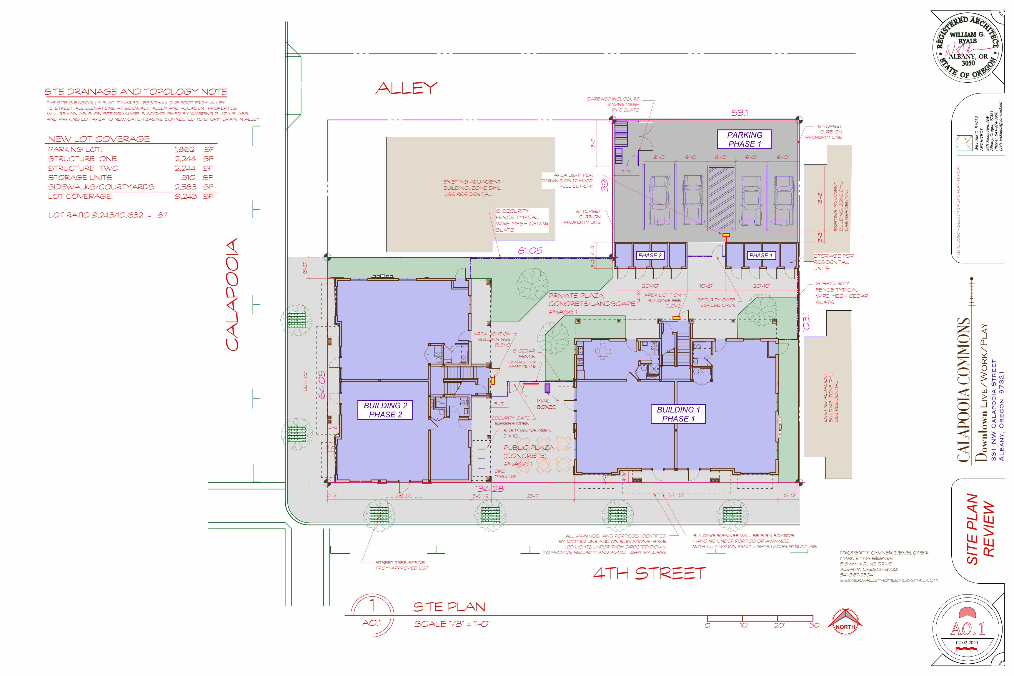
WIL
LIA
M G
. RY
ALS
Alb
any,
Ore
gon
973
2193
5 Jo
nes
Ave
. NW
Pho
ne:
541-
974-
0908
AR
CH
ITE
CT
ryal
s.ar
chite
ct@
com
cast
.net
331 N
W C
alapooia
Str
eet
Alban
y, O
regon
97321
CALA
POOI
A CO
MM
ONS!
Down
town L
ive
/W
or
k/
Pla
y
02-02-20200 31 2
PROPERTY OWNER/DEVELOPER MARK & TINA SIEGNER 516 NW KOUNS DRIVE ALBANY, OREGON 87321 541-967-2304 [email protected]
FE
B. 1
3, 2
020
- IS
SU
ED
FO
R S
ITE
PLA
N R
EV
IEW
D.W.
BUILDING 2 PHASE 2 BUILDING 1
PHASE 1
PHASE 1PHASE 2
PARKING PHASE 1
53.1
103
.1
134.28
64
.05
81.05
39
1A0.1
SITE PLANSCALE 1/8" = 1'-0"
4TH STREET
CA
LA
PO
OIA
NEW LOT COVERAGE PARKING LOT: 1,862 SF STRUCTURE ONE 2,244 SF STRUCTURE TWO 2,244 SF STORAGE UNITS 310 SF SIDEWALKS/COURTYARDS 2,583 SF LOT COVERAGE: 9,243 SF
LOT RATIO 9,243/10,632 = .87
0 10' 20' 30'
SIT
E P
LAN
R
EV
IEW
STORAGE FOR RESIDENTIAL UNITS
6' SECURITY FENCE TYPICAL WIRE MESH CEDAR SLATS
9'-0"9'-0"9'-0"9'-0" 8'-0"
3'-3
"18
'-6"
6'-0
"
20'-10"10'-9"20'-10"
4'-3
"
14'-6
"
6'-0"
MAIL BOXES
2'-5" 38'-5" 57'-10"
5'-0"
4'-0
"
6' CEDAR FENCE
SECURITY GATE EGRESS OPEN
SECURITY GATE EGRESS OPEN
3'-2
"
BIKE PARKING
GARBAGE INCLOSURE 5' WIRE MESH
PVC SLATS
ALLEY
6' SECURITY FENCE TYPICAL WIRE MESH CEDAR SLATS
STREET TREE SPECIE FROM APPROVED LIST
13'-0
"
7'-3"
6" TOPSET CURB ON
PROPERTY LINE
6" TOPSET CURB ON
PROPERTY LINE
5'-8 1/2" 23'-7"
58
'-4 1/2
"
EXISTING ADJACIENT BUILDING. ZONE DMU USE RESIDENTIAL
EX
ISTIN
G A
DJA
CIE
NT
BU
ILD
ING
. ZO
NE
DM
U
US
E R
ES
IDE
NTIA
L
EX
ISTIN
G A
DJA
CIE
NT
BU
ILD
ING
. ZO
NE
DM
U
US
E R
ES
IDE
NTIA
L
2'-0
"
3'-6
"
2'-0"
3'-6"
PUBLIC PLAZA (CONCRETE) PHASE 1
PRIVATE PLAZA CONCRETE/LANDSCAPE PHASE 1
NORTH A0.1
SITE DRAINAGE AND TOPOLOGY NOTETHE SITE IS BASICALLY FLAT. IT VARIES LESS THAN ONE FOOT FROM ALLEY TO STREET. ALL ELEVATIONS AT SIDEWALK, ALLEY AND ADJACENT PROPERTIES WILL REMAIN AS IS. ON SITE DRAINAGE IS ACOMPLISHED BY WARPING PLAZA SLABS AND PARKING LOT AREA TO NEW CATCH BASINS CONNECTED TO STORM DRAIN IN ALLEY
AREA LIGHT FOR PARKING ON 12' MAST
FULL CUT-OFF
AREA LIGHT ON BUILDING SEE
ELEVS
AREA LIGHT ON BUILDING SEE
ELEVS
BIKE PARKING AREA 5' X 10'
SIGNAGE FOR APARTMENTS
:ALL AWNINGS AND PORTICOS IDENTIFIED BY DOTTED LINE AND ON ELEVATIONS HAVE
LED LIGHTS UNDER THEM DIRECTED DOWN TO PROVIDE SECURITY AND AVOID LIGHT SPILLAGE
BUILDING SIGNAGE WILL BE SIGN BOARDS HANGING UNDER PORTICO OR AWNINGS WITH ILLIMINATION FROM LIGHTS UNDER STRUCTURE

WIL
LIA
M G
. RY
ALS
Alb
any,
Ore
gon
973
2193
5 Jo
nes
Ave
. NW
Pho
ne:
541-
974-
0908
AR
CH
ITE
CT
ryal
s.ar
chite
ct@
com
cast
.net
331 N
W C
alapooia
Str
eet
Alban
y, O
regon
97321
CALA
POOI
A CO
MM
ONS!
Down
town L
ive
/W
or
k/
Pla
y
02-02-20200 31 2
PROPERTY OWNER/DEVELOPER MARK & TINA SIEGNER 516 NW KOUNS DRIVE ALBANY, OREGON 87321 541-967-2304 [email protected]
FE
B. 1
3, 2
020
- IS
SU
ED
FO
R S
ITE
PLA
N R
EV
IEW
53.1
103
.1
134.28
64
.05
81.05
39
1A0.2
PRE-EXISTING SITE PLANSCALE 1/8" = 1'-0"
EXISTING LOT COVERAGE EXISTING PARKING LOT: 2,000 SF STRUCTURE ONE 2,575 SF STRUCTURE TWO 1,254 SF MISC SIDEWALKS 413 SF EXISTING COVERAGE: 6,242 SF
EXISTING STRUCTURE COVERAGE 1,254 SF
EXISTING STRUCTURE COVERAGE 2,575 SF
PRE-EXISTING PARKING AREA 2,000 SF
SIDEWALKS 413 SQ.FT.
LOT RATIO 6,242/10,632 = .59
NORTH
PR
E-E
XIS
TIN
G
SIT
E P
LAN
A0.2
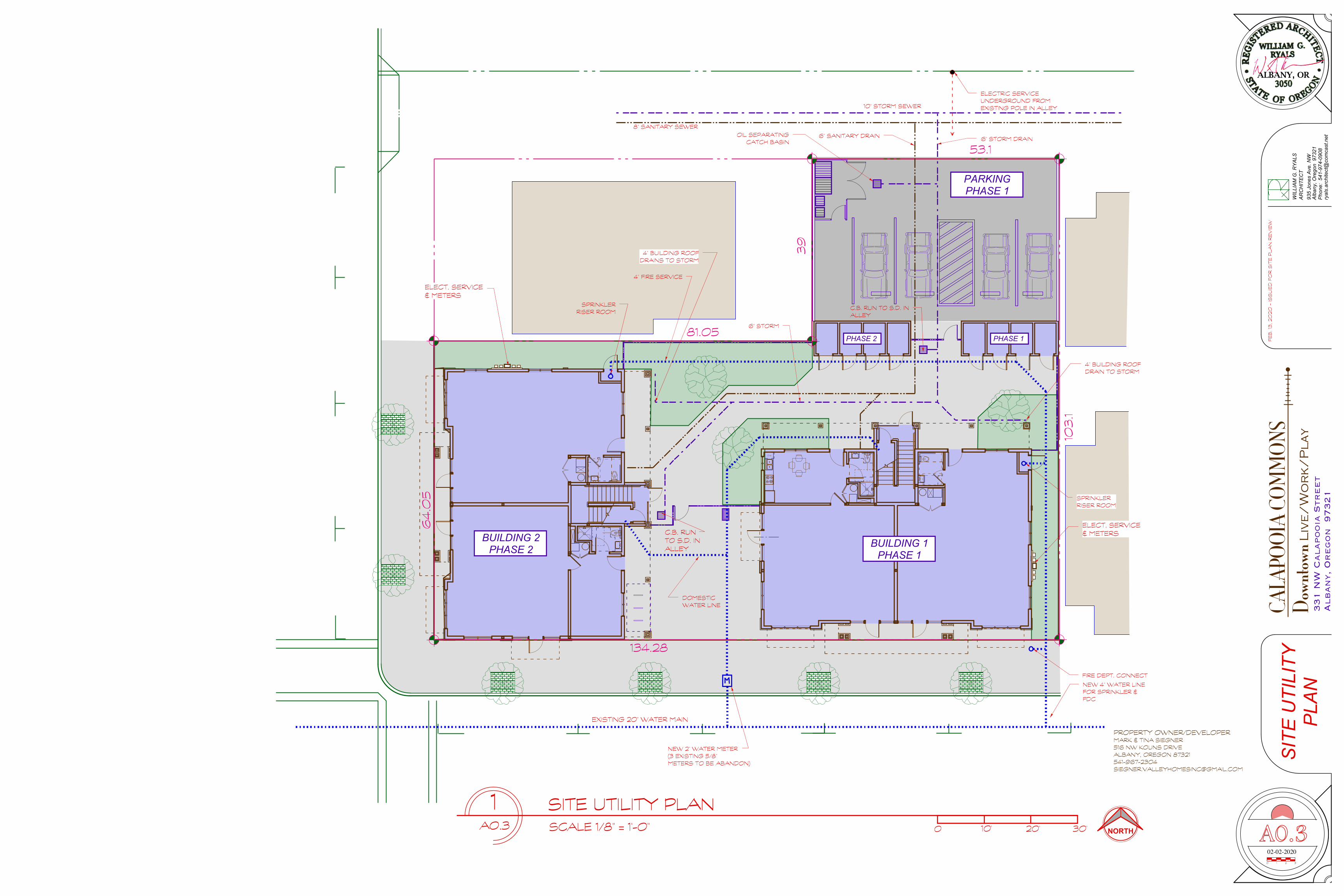
WIL
LIA
M G
. RY
ALS
Alb
any,
Ore
gon
973
2193
5 Jo
nes
Ave
. NW
Pho
ne:
541-
974-
0908
AR
CH
ITE
CT
ryal
s.ar
chite
ct@
com
cast
.net
331 N
W C
alapooia
Str
eet
Alban
y, O
regon
97321
CALA
POOI
A CO
MM
ONS!
Down
town L
ive
/W
or
k/
Pla
y
02-02-20200 31 2
PROPERTY OWNER/DEVELOPER MARK & TINA SIEGNER 516 NW KOUNS DRIVE ALBANY, OREGON 87321 541-967-2304 [email protected]
FE
B. 1
3, 2
020
- IS
SU
ED
FO
R S
ITE
PLA
N R
EV
IEW
D.W.
BUILDING 2 PHASE 2 BUILDING 1
PHASE 1
PHASE 1PHASE 2
PARKING PHASE 1
53.1
103
.1
134.28
64
.05
81.05
39
1A0.3
SITE UTILITY PLANSCALE 1/8" = 1'-0" 0 10' 20' 30'
ELECTRIC SERVICE UNDERGROUND FROM EXISTING POLE IN ALLEY
NEW 4" WATER LINE FOR SPRINKLER & FDC
FIRE DEPT. CONNECT
DOMESTIC WATER LINE
C.B. RUN TO S.D. IN ALLEY
10" STORM SEWER
8" SANITARY SEWER
C.B. RUN TO S.D. IN ALLEY
SPRINKLER RISER ROOM
ELECT. SERVICE & METERS
ELECT. SERVICE & METERS
SPRINKLER RISER ROOM
NORTH
4" FIRE SERVICE
6" STORM DRAIN6" SANITARY DRAINOIL SEPARATING CATCH BASIN
6" STORM
SIT
E U
TILI
TY
PLA
N
A0.3
NEW 2" WATER METER (3 EXISTING 5/8" METERS TO BE ABANDON)
EXISTING 20" WATER MAIN
4" BUILDING ROOF DRAINS TO STORM
4" BUILDING ROOF DRAIN TO STORM
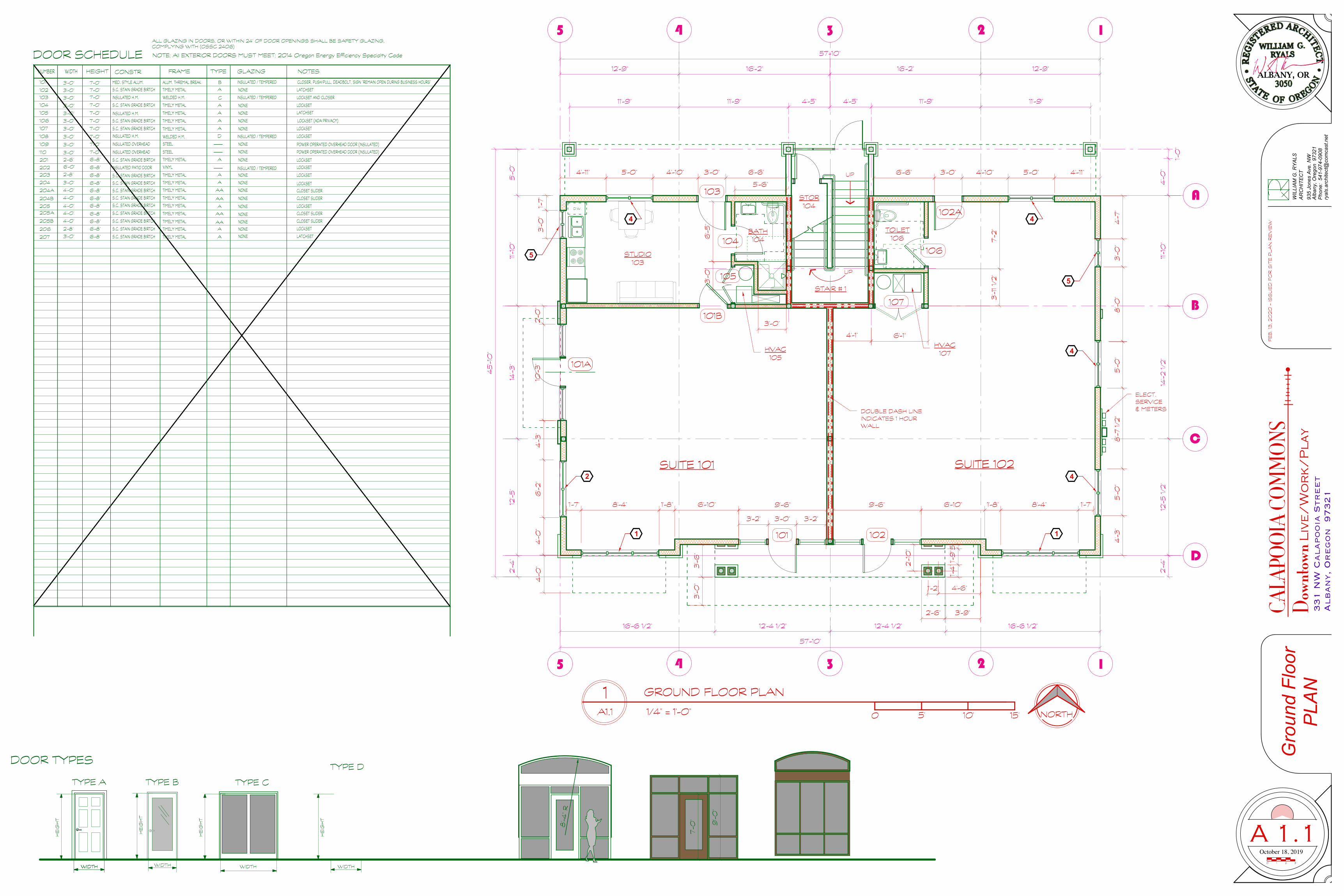
331 N
W C
alapooia
Str
eet
Alban
y, O
regon
97321
October 18, 2019
WIL
LIA
M G
. RY
ALS
Alb
any,
Ore
gon
973
2193
5 Jo
nes
Ave
. NW
Pho
ne:
541-
974-
0908
AR
CH
ITE
CT
ryal
s.ar
chite
ct@
com
cast
.net
0 31 2
CALA
POOI
A CO
MM
ONS!
Down
town L
ive
/W
or
k/
Pla
y
FE
B. 1
3, 2
020
- IS
SU
ED
FO
R S
ITE
PLA
N R
EV
IEW
NUMBER WIDTH HEIGHT CONSTR FRAME TYPE NOTES
TYPE A
HE
IGH
T
DOOR TYPES
TYPE CTYPE B
WIDTH
HE
IGH
T
DOOR SCHEDULE NOTE: All EXTERIOR DOORS MUST MEET: 2014 Oregon Energy Efficiency Specialty Code
WIDTH
GLAZING
101
3'-0"
3'-0"
3'-0"
MED. STYLE ALUM. ALUM. THREMAL BREAK B3'-0" 7'-0"
104
105
106
CLOSER, PUSH/PULL, DEADBOLT, SIGN "REMAIN OPEN DURING BUSINESS HOURS"
3'-0"
107
3'-0"
103
102
INSULATED H.M. WELDED H.M. C
3'-0"
INSULATED / TEMPERED
TYPE D
WIDTH
HE
IGH
T
INSULATED / TEMPERED LOCKSET AND CLOSER
ALL GLAZING IN DOORS, OR WITHIN 24" OF DOOR OPENINGS SHALL BE SAFETY GLAZING, COMPLYING WITH (OSSC 2406)
108
109
110
3'-0"
3'-0"
3'-0"
S.C. STAIN GRADE BIRTCH TIMELY METAL A LATCHSET
S.C. STAIN GRADE BIRTCH A
NONE
LOCKSET (ADA PRIVACY)TIMELY METAL
S.C. STAIN GRADE BIRTCH TIMELY METAL A LOCKSET
TIMELY METAL A NONE LATCHSET
NONE
7'-0"
7'-0"
7'-0"
7'-0"
7'-0"
S.C. STAIN GRADE BIRTCH7'-0" TIMELY METAL A LOCKSETNONE
INSULATED H.M.
INSULATED H.M.
WELDED H.M. D
NONE
INSULATED / TEMPERED LOCKSET7'-0"
7'-0"
7'-0"
INSULATED OVERHEAD STEEL
INSULATED OVERHEAD STEEL
NONE
NONE
POWER OPERATED OVERHEAD DOOR (INSULATED)
POWER OPERATED OVERHEAD DOOR (INSULATED)
201
202
203
204
205
206
207
2'-6"
6'-0"
2'-8"
3'-0"
4'-0"
4'-0"
4'-0"
4'-0"
6'-8"
6'-8"
6'-8"
6'-8"
6'-8"
6'-8"
6'-8"
6'-8"
S.C. STAIN GRADE BIRTCH
S.C. STAIN GRADE BIRTCH
S.C. STAIN GRADE BIRTCH
S.C. STAIN GRADE BIRTCH
S.C. STAIN GRADE BIRTCH
S.C. STAIN GRADE BIRTCH
S.C. STAIN GRADE BIRTCH
S.C. STAIN GRADE BIRTCH
S.C. STAIN GRADE BIRTCH
INSULATED PATIO DOOR
TIMELY METAL
VINYL
A
INSULATED / TEMPERED
NONE
TIMELY METAL
TIMELY METAL
TIMELY METAL
A
A
AA
NONE
NONE
NONE204A
204B
205A
205B
AA
AA
AA
A
TIMELY METAL
TIMELY METAL
TIMELY METAL
TIMELY METAL
TIMELY METAL
6'-8"
6'-8"
4'-0"
NONE
NONE
NONE
NONE
2'-8"
3'-0" 6'-8" S.C. STAIN GRADE BIRTCH TIMELY METAL
A
A
NONE
NONE LATCHSET
LOCKSET
CLOSET SLIDER
CLOSET SLIDER
CLOSET SLIDER
CLOSET SLIDER
LOCKSET
LOCKSET
LOCKSET
LOCKSET
LOCKSET
9'-0
"
7'-0
"
8'-4
" R
WIDTH
HE
IGH
T
WIDTH
A
B
C
5 14 23
D
11'-1
0"
14'-2
1/2
"12
'-5 1/2
"
57'-10"
12'-9" 16'-2" 16'-2" 12'-9"
11'-9" 11'-9" 4'-5" 4'-5" 11'-9" 11'-9"
4'-0
"
1'-0
"
2'-4
"
57'-10"
16'-6 1/2" 12'-4 1/2" 12'-4 1/2" 16'-6 1/2"
5 14 23
45
'-10
"
5'-0
"11'
-10
"14
'-3"
12'-5
"2'-4
"
6'-6" 3'-0" 4'-10" 5'-0" 4'-11"6'-6"3'-0"4'-10"5'-0"4'-11"
D.W.
GROUND FLOOR PLAN
1/4" = 1'-0" 0 5' 10' 15'
1A1.1
A 1.1
Gro
und
Floo
r P
LAN
NORTH
SUITE 101
STUDIO 103
TOILET 106
STOR 104
UP
UP
SUITE 102
101 1024
'-0"
6'-2
"4
'-3"
6'-10"1'-8"8'-4"1'-7" 9'-6" 6'-10" 1'-8" 8'-4" 1'-7"9'-6"
4'-3
"5
'-0"
8'-7
1/2
"5
'-0"
10'-3
"2'-0
"1'-
7"3
'-0"
6'-5
"
5'-6"
3'-0"
3'-0
"
7'-2
"3
'-11 1/
2"
6'-1"4'-1"
4'-0
" 3'-6
"3
'-0"
4'-6"1'-2"
2'-1
0" 5
"1'-
9"
1'-4
"
2'-6" 3'-9"
3'-2" 3'-0" 3'-2"
101A
4'-7
"3
'-0"
8'-0
"
103
104BATH 104
HVAC 105
105
101B
1 1
2 4
4
5
5
102A
106
HVAC 107
107
4
DOUBLE DASH LINE INDICATES 1 HOUR WALL
4
STAIR # 1
ELECT. SERVICE & METERS

331 N
W C
alapooia
Str
eet
Alban
y, O
regon
97321
October 18, 2019
WIL
LIA
M G
. RY
ALS
Alb
any,
Ore
gon
973
2193
5 Jo
nes
Ave
. NW
Pho
ne:
541-
974-
0908
AR
CH
ITE
CT
ryal
s.ar
chite
ct@
com
cast
.net
0 31 2
CALA
POOI
A CO
MM
ONS!
Down
town L
ive
/W
or
k/
Pla
y
FE
B. 1
3, 2
020
- IS
SU
ED
FO
R S
ITE
PLA
N R
EV
IEW
RE
F.
D.W.
RE
F.
D.W.
WA
SH
/ D
RY
WA
SH
/ D
RY
NORTH
SECOND FLOOR PLAN
1/4" = 1'-0" 0 5' 10' 15'
1A1.2
2nd
Floo
r P
lan
a1.2
KITCHEN
LIVING
DINING
UPDN
LIVING
DINING
UP
KITCHEN
STAIR
BEDROOMMASTER BEDROOM
MASTER BEDROOM
BEDROOM
BATH SHOWER SHOWER BATH
5'-11"3'-0"1'-5"1'-6"3'-7 1/2"6'-0"3'-4" 5'-11" 3'-0" 1'-5" 1'-6" 3'-7 1/2" 6'-0" 3'-4"
4'-7
1/2
"4
'-0"
3'-2
1/2
"2'-0
"4
'-0"
3'-8
"2'-0
"2'-7
"3
'-8"
5'-0
"3
'-9"
4'-7
1/2
"4
'-0"
3'-2
1/2
"2'-0
"4
'-0"
3'-8
"2'-0
"2'-7
"3
'-8"
5'-0
"3
'-9"
3'-5" 6'-0" 7'-2" 3'-3" 6'-0" 3'-2" 3'-2" 6'-0" 3'-3" 7'-2" 6'-0" 3'-4"
201
3
202
A
B
C
5 14 23
D
11'-1
0"
14'-2
1/2
"12
'-5 1/2
"
57'-10"
12'-9" 16'-2" 16'-2" 12'-9"
11'-9" 11'-9" 4'-5" 4'-5" 11'-9" 11'-9"
4'-0
"
1'-0
"
2'-4
"
57'-10"
16'-6 1/2" 12'-4 1/2" 12'-4 1/2" 16'-6 1/2"
5 14 23
45
'-10
"
5'-0
"11'
-10
"14
'-3"
12'-5
"2'-4
"
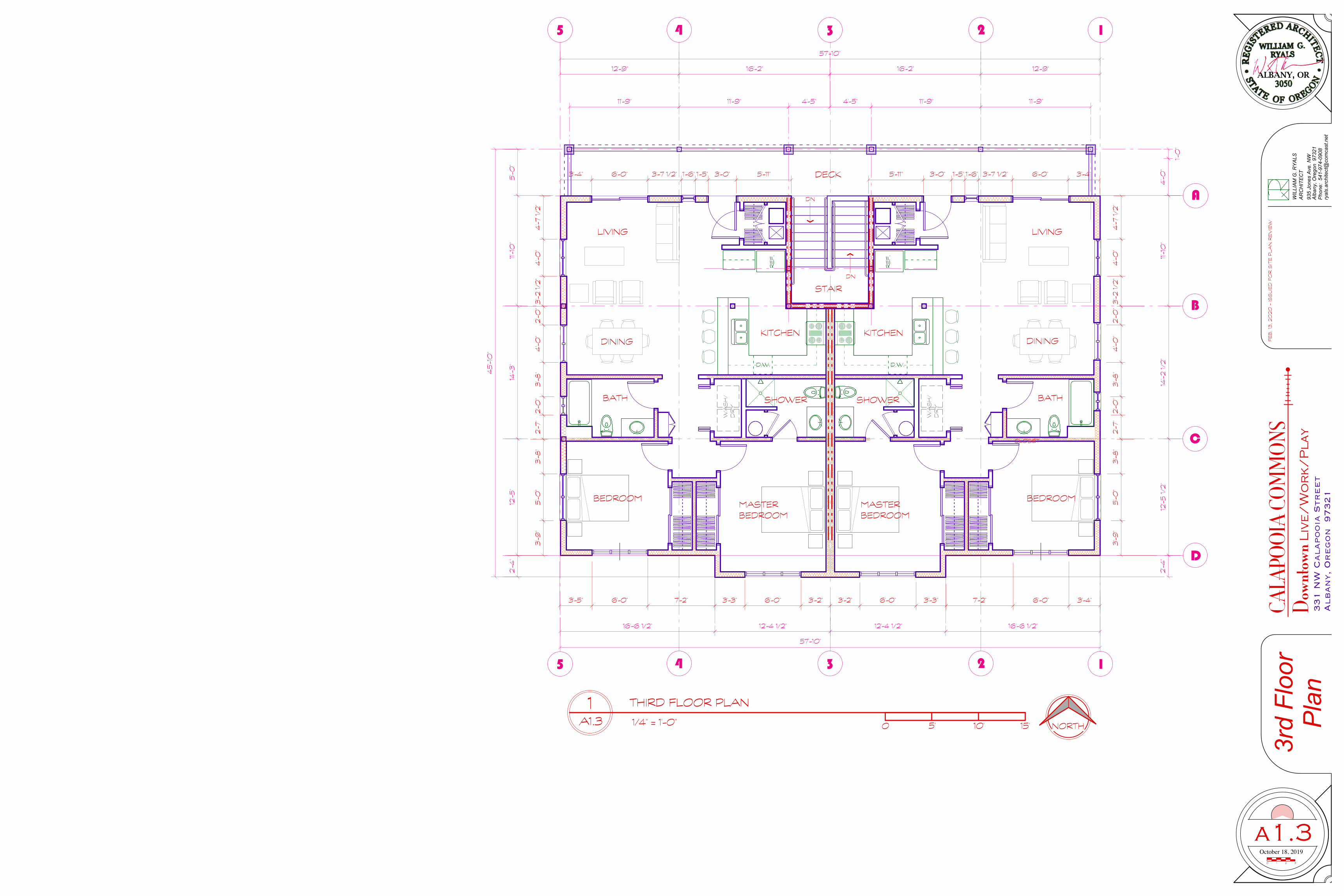
331 N
W C
alapooia
Str
eet
Alban
y, O
regon
97321
October 18, 2019
WIL
LIA
M G
. RY
ALS
Alb
any,
Ore
gon
973
2193
5 Jo
nes
Ave
. NW
Pho
ne:
541-
974-
0908
AR
CH
ITE
CT
ryal
s.ar
chite
ct@
com
cast
.net
0 31 2
CALA
POOI
A CO
MM
ONS!
Down
town L
ive
/W
or
k/
Pla
y
FE
B. 1
3, 2
020
- IS
SU
ED
FO
R S
ITE
PLA
N R
EV
IEW
RE
F.
D.W.
RE
F.
D.W.
WA
SH
/ D
RY
WA
SH
/ D
RY
A
B
C
5 14 23
D
11'-1
0"
14'-2
1/2
"12
'-5 1/2
"
57'-10"
12'-9" 16'-2" 16'-2" 12'-9"
11'-9" 11'-9" 4'-5" 4'-5" 11'-9" 11'-9"
4'-0
"
1'-0
"
2'-4
"
57'-10"
16'-6 1/2" 12'-4 1/2" 12'-4 1/2" 16'-6 1/2"
5 14 23
45
'-10
"
5'-0
"11'
-10
"14
'-3"
12'-5
"2'-4
"
NORTH
THIRD FLOOR PLAN
1/4" = 1'-0" 0 5' 10' 15'
1A1.3
3rd
Floo
r P
lan
a1.3
CLOSET
KITCHEN
LIVING
DINING
DN
LIVING
DINING
DN
KITCHEN
STAIR
BEDROOMMASTER BEDROOM
MASTER BEDROOM
BEDROOM
BATH SHOWER SHOWER BATH
DECK5'-11"3'-0"1'-5"1'-6"3'-7 1/2"6'-0"3'-4" 5'-11" 3'-0" 1'-5" 1'-6" 3'-7 1/2" 6'-0" 3'-4"
4'-7
1/2
"4
'-0"
3'-2
1/2
"2'-0
"4
'-0"
3'-8
"2'-0
"2'-7
"3
'-8"
5'-0
"3
'-9"
4'-7
1/2
"4
'-0"
3'-2
1/2
"2'-0
"4
'-0"
3'-8
"2'-0
"2'-7
"3
'-8"
5'-0
"3
'-9"
3'-5" 6'-0" 7'-2" 3'-3" 6'-0" 3'-2" 3'-2" 6'-0" 3'-3" 7'-2" 6'-0" 3'-4"
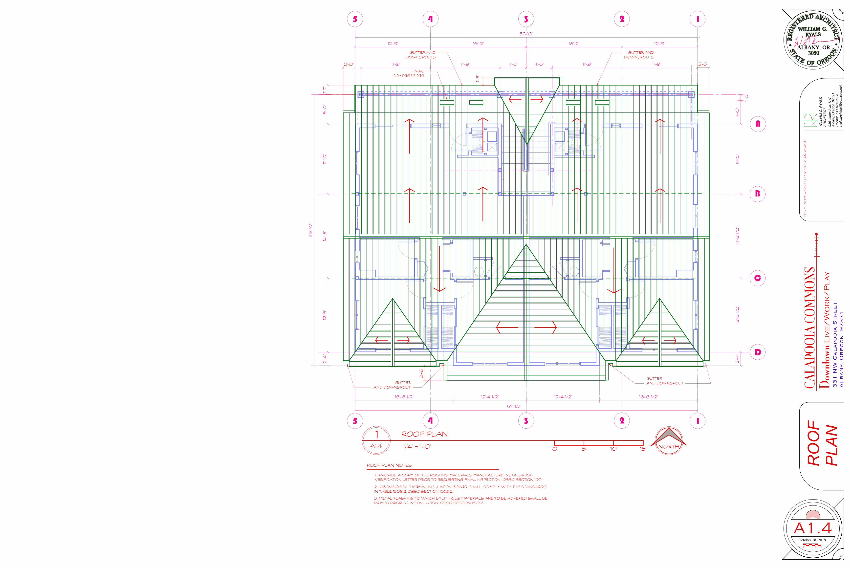
331 N
W C
alapooia
Str
eet
Alban
y, O
regon
97321
October 18, 2019
WIL
LIA
M G
. RY
ALS
Alb
any,
Ore
gon
973
2193
5 Jo
nes
Ave
. NW
Pho
ne:
541-
974-
0908
AR
CH
ITE
CT
ryal
s.ar
chite
ct@
com
cast
.net
0 31 2
CALA
POOI
A CO
MM
ONS!
Down
town L
ive
/W
or
k/
Pla
y
FE
B. 1
3, 2
020
- IS
SU
ED
FO
R S
ITE
PLA
N R
EV
IEW
A
B
C
5 14 23
D
11'-1
0"
14'-2
1/2
"12
'-5 1/2
"
57'-10"
12'-9" 16'-2" 16'-2" 12'-9"
11'-9" 11'-9" 4'-5" 4'-5" 11'-9" 11'-9"
4'-0
"
1'-0
"
2'-4
"
57'-10"
16'-6 1/2" 12'-4 1/2" 12'-4 1/2" 16'-6 1/2"
5 14 23
45
'-10
"
5'-0
"11'
-10
"14
'-3"
12'-5
"2'-4
"
A1.4
RO
OF
P
LANROOF PLAN
1/4" = 1'-0" 0 5' 10' 15'
1A1.4 NORTH
1. PROVIDE A COPY OF THE ROOFING MATERIALS MANUFACTURE INSTALLATION VERIFICATION LETTER PRIOR TO REQUESTING FINAL INSPECTION. OSSC SECTION 107
ROOF PLAN NOTES:
2. ABOVE-DECK THERMAL INSULATION BOARD SHALL COMPLY WITH THE STANDARDS IN TABLE 1509.2. OSSC SECTION 1509.2
3. METAL FLASHING TO WHICH BITUMINOUS MATERIALS ARE TO BE ADHERED SHALL BE PRIMED PRIOR TO INSTALLATION. OSSC SECTION 1510.6
GUTTER AND DOWNSPOUTS
GUTTER AND DOWNSPOUTGUTTER
AND DOWNSPOUT
GUTTER AND DOWNSPOUTS
1'-7"
2'-0" 2'-0"
1'-3
"
2'-6
"
HVAC COMPRESSORS

October 18, 2019
WIL
LIA
M G
. RY
ALS
Alb
any,
Ore
gon
973
2193
5 Jo
nes
Ave
. NW
Pho
ne:
541-
974-
0908
AR
CH
ITE
CT
ryal
s.ar
chite
ct@
com
cast
.net
0 31 2
331 N
W C
alapooia
Str
eet
Alban
y, O
regon
97321
CALA
POOI
A CO
URT!
Down
town L
ive
/W
or
k/
Pla
y
FE
B. 1
3, 2
020
- IS
SU
ED
FO
R S
ITE
PLA
N R
EV
IEW
533
A B C D 5 4 2 13
BU
ILD
ING
E
LEV
ATI
ON
S
A 3.0
WEST BUILDING ELEVATION
1/4" = 1'-0" 0 5' 10' 15'
2A3.0
SOUTH BUILDING ELEVATION
1/4" = 1'-0" 0 5' 10' 15'
1A3.0
7'-6
"9
'-0"
14'-0
"
40
'-10
"
9'-0
"1'-
3"
2ND FLOOR
3RD FLOOR
ROOF PEAK
2'-0
"5
'-0"
4'-0
"3
'-0"
3'-0
"4
'-0"
3'-6
"5
'-0"
10'-0
"
8'-4
" R
2'-6
"4
'-6"
2'-6
"4
'-6"
2'-6
"4
'-6"
2'-6
"4
'-6"
10'-0
"
2'-6
"
8'-3
1/2
" R
2'-6
"1'-
0"
1'-6
"
9'-0
"
7'-0
"
2'-6
"7'
-0"
2'-6
"
6
12
6
12
6
12
4
12
212
ALUMINIUM STOREFRONT TYPICAL
POWDER COATED METAL AWNING
SMOOTH FINISH COMPOSIT LAP SIDING
ARCHITECTURAL COMP ROOF
ROOF VENT WITH WOOD
TRIMHARTI-SHINGLE
COMPOSITE WINDOW FRAME WITH WOOD TRIM
WOOD BEAMS, BRACKETS AND COLUMN TRIM
SMOOTH FINISH COMPOSIT LAP SIDING
ALUMINIUM STOREFRONT
ROOF VENT WITH WOOD
TRIM
HARDI-SHINGLE COMPOSITE
SIDING
ARCHITECTURAL COMP ROOF
CONT. GUTTERS
SMOOTH FINISH COMPOSIT LAP SIDINGCULTURED STONE
HONED
WOOD BEAMS, TRIM AND DETAILS
DOWNSPOUT COMPOSITE WINDOW FRAME WITH WOOD TRIM

ryal
s.ar
chite
ct@
com
cast
.net
331 N
W C
alapooia
Str
eet
Alban
y, O
regon
97321
CALA
POOI
A CO
URT!
Down
town L
ive
/W
or
k/
Pla
y
October 18, 2019
WIL
LIA
M G
. RY
ALS
Alb
any,
Ore
gon
973
2193
5 Jo
nes
Ave
. NW
Pho
ne:
541-
974-
0908
AR
CH
ITE
CT
ryal
s.ar
chite
ct@
com
cast
.net
0 31 2
331 N
W C
alapooia
Str
eet
Alban
y, O
regon
97321
CALA
POOI
A CO
URT!
Down
town L
ive
/W
or
k/
Pla
y
FE
B. 1
3, 2
020
- IS
SU
ED
FO
R S
ITE
PLA
N R
EV
IEW
3
3
3
3
SPRINKLER RISER ROOM
5421 3A B C D
BU
ILD
ING
E
LEV
ATI
ON
S
A 3.0
BU
ILD
ING
E
LEV
ATI
ON
S
A 3.1
EAST BUILDING ELEVATION
1/4" = 1'-0" 0 5' 10' 15'
2A3.1
NORTH BUILDING ELEVATION
1/4" = 1'-0" 0 5' 10' 15'
1A3.1
7'-6
"9
'-0"
14'-0
"
40
'-10
"
9'-0
"1'-
3"
2ND FLOOR
3RD FLOOR
ROOF PEAK
3'-0
"4
'-0"
2'-0
"7'
-2"
2'-6
"
4'-0
"4
'-0"
4'-0
"4
'-0"
3'-0
"4
'-0"
5'-0
"2'-0
"
3'-0
"4
'-0"
3'-6
"3
'-6"
5'-0
"2'-0
"
3'-0
"4
'-0"
4'-8
"3
'-4"
6
12
4
12
212
TOP PLATE
SMOOTH FINISH COMPOSIT LAP SIDING
ELECT. SERVICE AND METERS
ARCHITECTURAL COMP ROOF
ROOF VENT WITH WOOD
TRIM HARTI-SHINGLE
COMPOSITE WINDOW FRAME WITH WOOD TRIMWOOD BEAMS, BRACKETS
AND COLUMN TRIM
SMOOTH FINISH COMPOSIT LAP SIDING
ARCHITECTURAL COMP ROOF
CONT. GUTTERS
SMOOTH FINISH COMPOSIT LAP SIDING
CULTURED STONE HONED
WOOD BEAMS, TRIM AND DETAILS
DOWNSPOUT
COMPOSITE WINDOW FRAME WITH WOOD TRIM
SPLIT HVAC HEATPUMP
POWDER COATED METAL RAILING
MONOPLY MEMBRANE
POWDER COATED METAL SECURITY
GATE
SECURITY LIGHTING FULL CUT-OFF