landtecthermal gas mass flow meter operations and
TRANSCRIPT
LANDTEC THERMAL GAS MASS FLOW METER
Operations andInstruction Manual
For ACCU-FLO Models LIA and LRA
Make the Wise Choice.Choose LANDTEC ACCU-FLO Meters.
LANDTEC850 South Via Lata, Suite 112
Colton, CA 92324Tel (800) 821-0496Fax (909) 825-0591
www.landtecna.com

O p e r a t i o n s a n d I n s t r u c t i o n M a n u a l 3L A N D T E C
REV. 16-LIA/LRA
Table of Contents
Introduction Welcome . . . . . . . . . . . . . . . . . . . . . . . . . . . . . . . . . . . . . . . . . . . . . . . . . . . . . . . . . . . . . . . . . . . 5
SECTION A Unpacking Your LANDTEC Meter . . . . . . . . . . . . . . . . . . . . . . . . . . . . . . . . . . . . . . . . . . . . . . . 9
Getting Started Maintenance . . . . . . . . . . . . . . . . . . . . . . . . . . . . . . . . . . . . . . . . . . . . . . . . . . . . . . . . . . . . . . . . 9
Calibration . . . . . . . . . . . . . . . . . . . . . . . . . . . . . . . . . . . . . . . . . . . . . . . . . . . . . . . . . . . . . . . . . . 9
Installation and Mounting . . . . . . . . . . . . . . . . . . . . . . . . . . . . . . . . . . . . . . . . . . . . . . . . . . . . . 10
Locating Proper Wiring Diagram . . . . . . . . . . . . . . . . . . . . . . . . . . . . . . . . . . . . . . . . . . . . . . . . 10
Insertion Flow Meter Application . . . . . . . . . . . . . . . . . . . . . . . . . . . . . . . . . . . . . . . . . . . . . . . 11
LANDTEC Valve Assembly Operation . . . . . . . . . . . . . . . . . . . . . . . . . . . . . . . . . . . . . . . . . . . . . 11
Compression Fitting Operation . . . . . . . . . . . . . . . . . . . . . . . . . . . . . . . . . . . . . . . . . . . . . . . . . 12
Installation Instructions . . . . . . . . . . . . . . . . . . . . . . . . . . . . . . . . . . . . . . . . . . . . . . . . . . . . . . . 12
Captive Flow Conditioners . . . . . . . . . . . . . . . . . . . . . . . . . . . . . . . . . . . . . . . . . . . . . . . . . . . . . 13
Probe Insertion Guideline Drawing . . . . . . . . . . . . . . . . . . . . . . . . . . . . . . . . . . . . . . . . . . . . . . 14
Installation Depth Chart . . . . . . . . . . . . . . . . . . . . . . . . . . . . . . . . . . . . . . . . . . . . . . . . . . . . . . . 15
Large Duct or Stack Applications . . . . . . . . . . . . . . . . . . . . . . . . . . . . . . . . . . . . . . . . . . . . . . . . 16
In-line Flow Meter Application. . . . . . . . . . . . . . . . . . . . . . . . . . . . . . . . . . . . . . . . . . . . . . . . . . 17
Terminal Hookup ACCU-FLO Integral (Series LIA). . . . . . . . . . . . . . . . . . . . . . . . . . . . . . . . . . . 18
24 VDC ACCU-FLO Integral Terminals Series LIA. . . . . . . . . . . . . . . . . . . . . . . . . . . . . . . . . . . . 19
AC Powered ACCU-FLO and DC Powered ACCU-FLO
Integral Terminals (Series LIA) . . . . . . . . . . . . . . . . . . . . . . . . . . . . . . . . . . . . . . . . . . . . . . . 20
Terminal Hookup ACCU-FLO Remote (Series LRA) . . . . . . . . . . . . . . . . . . . . . . . . . . . . . . . . . . 21
24 VDC ACCU-FLO Remote Terminals (Series LRA). . . . . . . . . . . . . . . . . . . . . . . . . . . . . . . . . . 22
AC Powered ACCU-FLO and DC Powered ACCU-FLO
Remote Series Terminals (Series LRA) . . . . . . . . . . . . . . . . . . . . . . . . . . . . . . . . . . . . . . . . . 23
Junction Box Wiring Terminals for Remote Style Meters . . . . . . . . . . . . . . . . . . . . . . . . . . . . 24
SECTION B Principle of Operation. . . . . . . . . . . . . . . . . . . . . . . . . . . . . . . . . . . . . . . . . . . . . . . . . . . . . . . . . 27 Specifications Features and Benefits . . . . . . . . . . . . . . . . . . . . . . . . . . . . . . . . . . . . . . . . . . . . . . . . . . . . . . . . . 28
LANDTEC ACCU-FLO Styles & Specifications . . . . . . . . . . . . . . . . . . . . . . . . . . . . . . . . . . . . . . . 29
LANDTEC ACCU-FLO Organic (OLED) Display . . . . . . . . . . . . . . . . . . . . . . . . . . . . . . . . . . . . . . 30
Approvals . . . . . . . . . . . . . . . . . . . . . . . . . . . . . . . . . . . . . . . . . . . . . . . . . . . . . . . . . . . . . . . . . . . 31
SECTION C LIA Series Integral Style Flow Meters . . . . . . . . . . . . . . . . . . . . . . . . . . . . . . . . . . . . . . . . . . . . 35 Drawings LRA Series Remote Style Flow Meters. . . . . . . . . . . . . . . . . . . . . . . . . . . . . . . . . . . . . . . . . . . . 36
Remote Bracket Layout. . . . . . . . . . . . . . . . . . . . . . . . . . . . . . . . . . . . . . . . . . . . . . . . . . . . . . . . 37
Mounting Hardware: SVA05 Series Isolation Valve Assembly for Insertion Meters . . . . . . . . . . . . . . . . . . . . . . 38 STCF Series Teflon Ferrule Compression Fitting . . . . . . . . . . . . . . . . . . . . . . . . . . . . . . . . . 38 SVA05 Series Isolation Valve Assembly Detail . . . . . . . . . . . . . . . . . . . . . . . . . . . . . . . . . . 38 Mounting Plate for Thin Walled Ducts . . . . . . . . . . . . . . . . . . . . . . . . . . . . . . . . . . . . . . . . 38
continued on next page
L A N D T E C O p e r a t i o n s a n d I n s t r u c t i o n M a n u a l4
REV. 16-LIA/LRA
SECTION C SVA05LP Low Pressure Isolation Valve Assembly. . . . . . . . . . . . . . . . . . . . . . . . . . . . . . . . . . . 39 Drawings In-Line and Insertion Flanges . . . . . . . . . . . . . . . . . . . . . . . . . . . . . . . . . . . . . . . . . . . . . . . . . . . 40
SECTION D Common Diagnostics. . . . . . . . . . . . . . . . . . . . . . . . . . . . . . . . . . . . . . . . . . . . . . . . . . . . . . . . . . 43
Diagnostics In-Situ Calibration Check. . . . . . . . . . . . . . . . . . . . . . . . . . . . . . . . . . . . . . . . . . . . . . . . . . . . . . . 45
SECTION E Limited Warranty. . . . . . . . . . . . . . . . . . . . . . . . . . . . . . . . . . . . . . . . . . . . . . . . . . . . . . . . . . . . . 49
Warranties and Service Work Cancellation/Return Policy . . . . . . . . . . . . . . . . . . . . . . . . . . . . . . . . . . . . . . . . . . . . . . . . . . . . . 49
Returning Your LANDTEC Flow Meter . . . . . . . . . . . . . . . . . . . . . . . . . . . . . . . . . . . . . . . . . . . . 51
Return Material Authorization Form . . . . . . . . . . . . . . . . . . . . . . . . . . . . . . . . . . . . . . . . . . . . . 52
SECTION F Modbus Register Listing . . . . . . . . . . . . . . . . . . . . . . . . . . . . . . . . . . . . . . . . . . . . . . . . . . . . . . . 55
Modbus Modbus Protocol & Function Codes . . . . . . . . . . . . . . . . . . . . . . . . . . . . . . . . . . . . . . . . . . . . . 56
LANDTEC Register Output Format . . . . . . . . . . . . . . . . . . . . . . . . . . . . . . . . . . . . . . . . . . . . . . . 59
LANDTEC Addresser Software . . . . . . . . . . . . . . . . . . . . . . . . . . . . . . . . . . . . . . . . . . . . . . . . . . 59
LANDTEC Addresser Typical Printout (Version 3.14) . . . . . . . . . . . . . . . . . . . . . . . . . . . . . . . . 60
SECTION G LANDTEC ACCU-FLO™ Field Programmable “Dongle” . . . . . . . . . . . . . . . . . . . . . . . . . . . . . . . 64
Appendix Correction Factors For Varying Gas Mixes . . . . . . . . . . . . . . . . . . . . . . . . . . . . . . . . . . . . . . . . 65
Installations Where Pipe Condensation May Develop. . . . . . . . . . . . . . . . . . . . . . . . . . . . . . . 65
J-Box and Upstream Orientation . . . . . . . . . . . . . . . . . . . . . . . . . . . . . . . . . . . . . . . . . . . . . . . . 66
What Is a Thermal Mass Flow Meter?. . . . . . . . . . . . . . . . . . . . . . . . . . . . . . . . . . . . . . . . . . . . 67

O p e r a t i o n s a n d I n s t r u c t i o n M a n u a l 5
Welcome
We are pleased that you have purchased a LANDTEC Mass Flow Meter for your requirement. Wehope that you are satisfied with the performance, operation and design of our highly precise, NISTtraceable Thermal Gas Mass Flow Meter.
LANDTEC is your source for monitoring, measuring and controlling the gas mass flow in yourindustrial process, building management system or environmental appli cation. Our high performance,NIST Traceable,Thermal Mass Flow Meters will help increase productivity, reduce energy costs,maximize product yields, and/ or help reduce environmental insult. LANDTEC provides high quality In-Line and Insertion Thermal Mass Flow Meters for a wide variety of industrial, commercial, andenvironmental monitoring needs, including carbon credit verification for Greenhouse Gas reduction.
LANDTEC Flow Meters measure mass flow directly — there is no need for ancillary instrumentationsuch as temperature or pressure transmitters. Furthermore, our instruments have exceptional signalsensitivity, have no moving parts, require little if any maintenance, have negligible pressure drop andhave a turndown up to 100 to 1, and resolve as much as 1000 to 1. LANDTEC Flow Meters canmeasure the mass flow rate and consumption of air, oxygen, natural gas, nitrogen, digester gas,biogas, flare gas, hydrogen, argon, carbon dioxide and other gases and gas mixes.
The ACCU-FLO Meter is the latest addition to our family of high performance Thermal Mass FlowMeters. It features a bright graphical display of Flow Rate,Total and Temperature, robust industrialenclosure, and easy to access power and output terminals. LANDTEC ACCU-FLO meter has a dual-compartment windowed enclosure featuring a very high contrast photo-emissive OLED display with anew photocell activated Screen Saver. The rear compartment, which is separated from theelectronics, has large, easy to access and well marked ter minals, for ease of customer wiring. It ispowered by 24 VDC (12 VDC optional, or 115/230 VAC). The power dissipation is under 2.5 watts (e.g.under 100 ma at 24 VDC for the DC version.)
Please let us know if we can assist you in any way with your LANDTEC Flow Meter, or if you have anyquestions about its installation, operation, or features. Simply phone us at 800-LANDTEC, or visit ourwebsite at WWW.LANDTECNA.COM.
L A N D T E C
REV. 16-LIA/LRA


Section
GETTING STARTED
A


O p e r a t i o n s a n d I n s t r u c t i o n M a n u a l
UNpACkING YOUR LANDTEC METER
Your LANDTEC flow meter is a sensitive, yet rugged,
precision built electronic instrument. Upon delivery, care
should be taken when opening the shipping container and
removing your meter. The meter should be inspected for any
damage that may have occurred during transit. If damage is
found, please contact the carrier immediately to place a
claim for damaged goods. The contents of the container
should be checked against the packing list for any
discrepancies. If there are any questions as to the contents
or configuration of the equipment including calibration
ranges, or, mounting hardware, contact LANDTEC as soon as
possible. Please save shipping container and packaging
materials (including PVC tube probe protector on LANDTEC
Insertion Flow Meters) in case the unit needs to be returned
for any reason.
MAINTENANCE
LANDTEC thermal mass flow meters essentially require little
or no maintenance. While the sensing element is somewhat
resistant to dirt and particulate build up, it may become
necessary to clean it from time to time if mounted in
extremely dirty environments. NOTE: ALWAYS REMOVE THE
POWER PRIOR TO ANY CLEANING OR MAINTENANCE. A
detergent or appropriate non-corrosive solvent for removing
the buildup may be required. A soft brush can be used
to gently clean the sensing element’s surface, using caution
to avoid damaging the sensor elements (the RTDs). If any
disassembly is necessary, contact LANDTEC for instructions.
In general, it is recommended that your LANDTEC Thermal
Mass Flow Meter be returned to the factory if cleaning,
repair, or recalibration is needed. This is usually the most
cost-effective and reliable alternative.
CALIBRATION
LANDTEC ACCU-FLO Meter has continuous diag nostics. The
raw cali bration milliwats (mw) is always displayed in the
upper left hand corner of the meter's display. At any time,
you can check this reading at a “no flow” condition and
compare the reading to the original re ported “zero flow”
value noted on the last few lines of your meter’s Certificate
of Conformance or the flow meter’s data tag. This diagnostic
procedure not only checks the sensor performance and the
“live zero” calibration point, but it verifies that the sensor is
clean. It essentially provides a means to validate the meter’s
performance, verifies that there is no shift or drift, and
eliminates the need for annual factory calibrations. This
simple field diagnostic procedure also verifies that the sensor
is free from contamination, even without inspection. See “In-
Situ Calibration Check” on page 46.
Getting Started
9L A N D T E C
REV. 16-LIA/LRA
! CAUTION cable glands shipped with unit are for shipping purposes only.
Remove shipping cable glands before installing.
! CAUTION If installing in a Class I hazardous location the installation
must comply with appropriate electrical codes.
! CAUTION Installer must supply proper ground and bond wire for the
transmitter and the sensor per appropriate electrical codes
L A N D T E C O p e r a t i o n s a n d I n s t r u c t i o n M a n u a l10
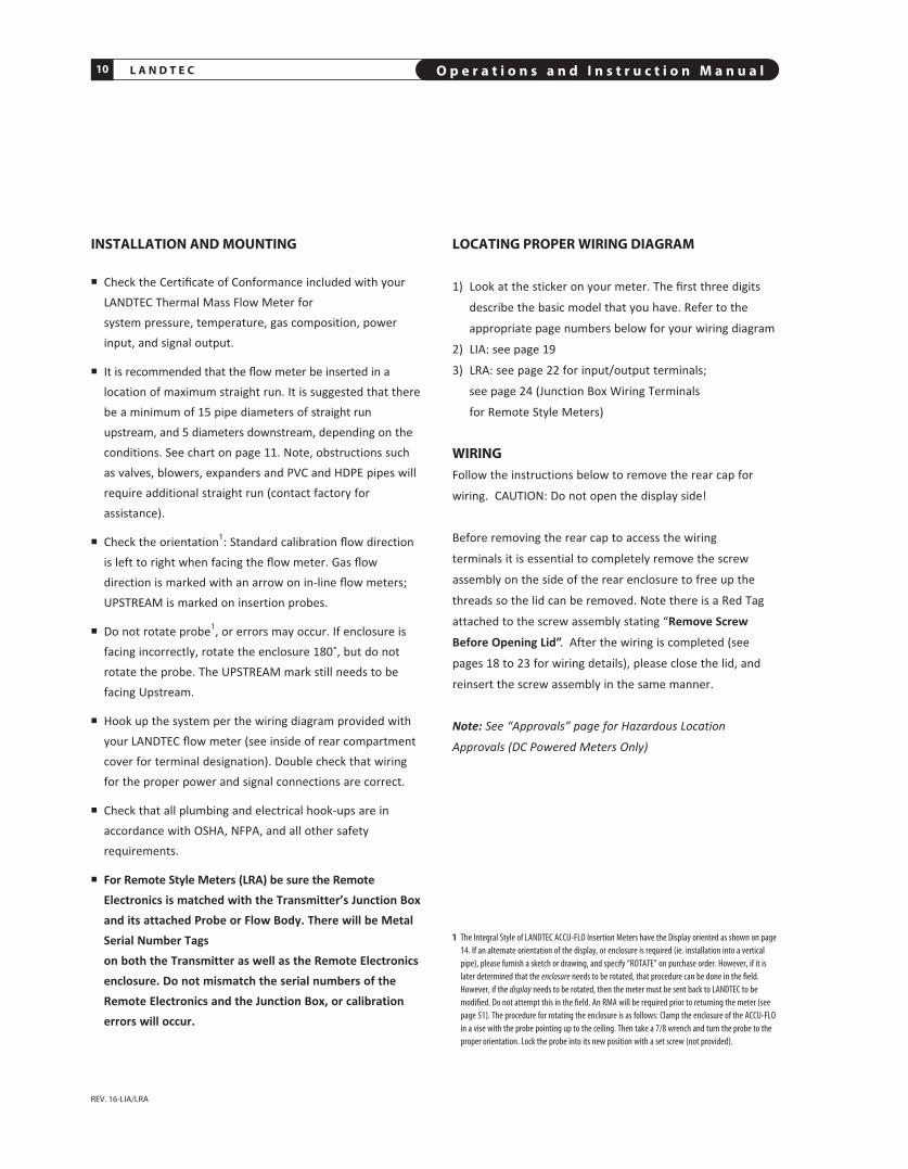
INSTALLATION AND MOUNTING
n Check the Certificate of Conformance included with yourLANDTEC Thermal Mass Flow Meter for system pressure, temperature, gas composition, powerinput, and signal output.
n It is recommended that the flow meter be inserted in alocation of maximum straight run. It is suggested that therebe a minimum of 15 pipe diameters of straight runupstream, and 5 diameters downstream, depending on theconditions. See chart on page 11. Note, obstructions suchas valves, blowers, expand ers and PVC and HDPE pipes willrequire additional straight run (contact factory forassistance).
n Check the orientation1: Standard calibration flow directionis left to right when facing the flow meter. Gas flowdirection is marked with an arrow on in-line flow meters;UPSTREAM is marked on insertion probes.
n Do not rotate probe1, or errors may occur. If enclosure isfacing incorrectly, rotate the enclosure 180˚, but do notrotate the probe. The UPSTREAM mark still needs to befacing Upstream.
n Hook up the system per the wiring diagram provided withyour LANDTEC flow meter (see inside of rear compartmentcover for terminal designation). Double check that wiringfor the proper power and signal connections are correct.
n Check that all plumbing and electrical hook-ups are inaccordance with OSHA, NFPA, and all other safetyrequirements.
n For Remote Style Meters (LRA) be sure the RemoteElectronics is matched with the Transmitter’s Junction Boxand its attached Probe or Flow Body. There will be MetalSerial Number Tags on both the Transmitter as well as the Remote Electronicsenclosure. Do not mismatch the serial numbers of theRemote Electronics and the Junction Box, or calibrationerrors will occur.
LOCATING pROpER WIRING DIAGRAM
1) Look at the sticker on your meter. The first three digits
describe the basic model that you have. Refer to the
appropriate page numbers below for your wiring diagram
2) LIA: see page 19
3) LRA: see page 22 for input/output terminals;
see page 24 (Junction Box Wiring Terminals
for Remote Style Meters)
WIRINGFollow the instructions below to remove the rear cap for
wiring. CAUTION: Do not open the display side!
Before removing the rear cap to access the wiring
terminals it is essential to completely remove the screw
assembly on the side of the rear enclosure to free up the
threads so the lid can be removed. Note there is a Red Tag
attached to the screw assembly stating “Remove Screw
Before Opening Lid”. After the wiring is completed (see
pages 18 to 23 for wiring details), please close the lid, and
reinsert the screw assembly in the same manner.
Note: See “Approvals” page for Hazardous LocationApprovals (DC Powered Meters Only)
REV. 16-LIA/LRA
1 The Integral Style of LANDTEC ACCU-FLO Insertion Meters have the Display oriented as shown on page14. If an alternate orientation of the display, or enclosure is required (ie. installation into a verticalpipe), please furnish a sketch or drawing, and specify “ROTATE” on purchase order. However, if it islater determined that the enclosure needs to be rotated, that procedure can be done in the field.However, if the display needs to be rotated, then the meter must be sent back to LANDTEC to bemodified. Do not attempt this in the field. An RMA will be required prior to returning the meter (seepage 51). The procedure for rotating the enclosure is as follows: Clamp the enclosure of the ACCU-FLOin a vise with the probe pointing up to the ceiling. Then take a 7/8 wrench and turn the probe to theproper orientation. Lock the probe into its new position with a set screw (not provided).

O p e r a t i o n s a n d I n s t r u c t i o n M a n u a l 11L A N D T E C
REV. 16-LIA/LRA
FLOW pROFILE AND INSTALLATIONCONSIDERATIONS
Insertion Flow Meters, although generally easier to install
that In-Line Flow Meters, require proper installation, and a
well developed flow profile, in order to perform properly.
Please refer to the section on the following pages titled
PROBE INSERTION GUIDELINE DRAWING (page 14) and
INSTALLATION DEPTH CHART (page 15).
LANDTEC VALVE ASSEMBLY OpERATION
Valve assemblies (SVA05 and SVA05LP) are an op tional
mounting hardware for Insertion Style Flow Meters (see
pages 38 and 39). They allow the removal of insertion-style
meters for service, cleaning, recali bration, relocation, etc.
without the need to “shut-down” your process. The probe
insertion depth is adjustable to permit sensor to be located
at center to optimize measurement accuracy. (Refer to
PROBE IN SERTION GUIDE LINE DRAWING and CHART, pages 14
& 15.) The ball valve will seal off leaks of the process gas at
the point of insertion after the probe assembly has been
removed. The assembly includes a valve, threadolet,
compression fitting with Teflon ferrule, a cable restraint, and
two collar clamps.
A threaded half coupling (3/4" FNPT) properly sized to
accom modate the isolation valve retractor assembly must be
fitted to the pipe/duct to which the insertion probe will be
inserted. Avoid T-Fittings since they will disturb the flow
profile, and effectively reduce the measurement area. Direct
threading together (or with necessary bushings) of the
retractor assembly may be required. In other cases, the
threadolet must be welded in place and a clearance hole
must be drilled through the pipe/ duct to accept the probe
assembly. If the pipe/duct is under pressure during
installation, a hot tap drill (not available through LANDTEC)
may be required.
FLOW CONDITIONING AND STRAIGHT RUN
Although a minimum of 15 pipe diameters of upstream
straight run is commonly recommended, to absolutely assure
that the flow profile is well developed at the point of
measurement, either use Flow Conditioners (standard in
LANDTEC In-Line Flow Meters, 1/2" and larger, and also
available as assemblies for Insertion Flow Meters, see page
13), or consider additional straight run. The Chart below
provides examples of the amount of straight run
that would virtually assure that there are no flow
disturbances at the point of measurement.
N O T E : Detailed Drawingsare shown on pages38 & 39.
Insertion Flow Meter Application
IMPORTANCE OF FLOW CONDITIONINGRecommended Pipe Diameters Upstream
One 90˚ Elbow
Two 90˚ Elbows in the same plane
Two 90˚ Elbows in different planes
4:1 Area Reduction
4:1 Area Expansion
Multiple Disturbance
3
5
9
3
10
TBD
1 This column applies to In-Line Flow Meters, which come standard with built-in Flow Conditioners, as well as Insertion Meters,when provided with upstream Captive Flow Conditioners (see page 13).
D I s T U R B A N C E
15
20
At least 40
15
At least 30
To Be Determined
WITHOUTFLOW CONDITIONING
Minimum IndustryRecommendation
WITH FLOWCONDITIONING1
LANDTECRecommendation
L A N D T E C O p e r a t i o n s a n d I n s t r u c t i o n M a n u a l12
REV. 16-LIA/LRA
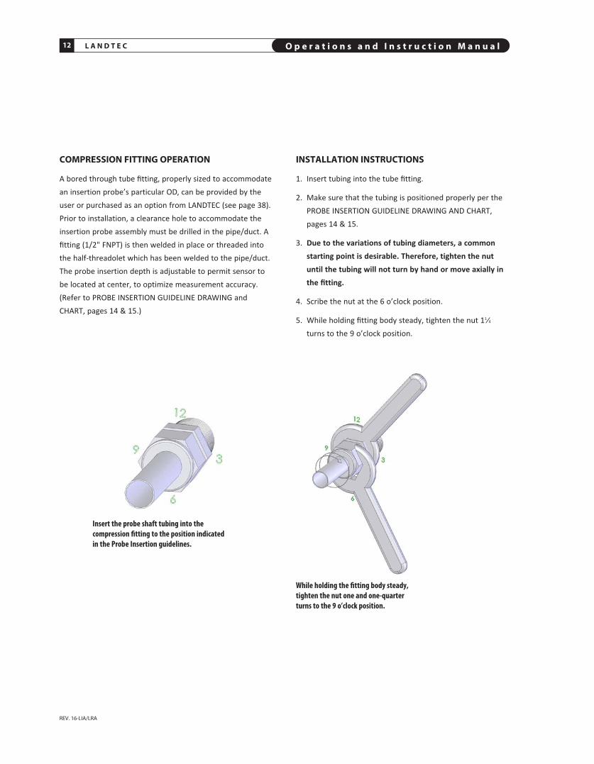
COMpRESSION FITTING OpERATION
A bored through tube fitting, properly sized to accommodatean insertion probe’s particular OD, can be provided by theuser or purchased as an option from LANDTEC (see page 38).Prior to installation, a clearance hole to accommodate theinsertion probe assembly must be drilled in the pipe/duct. Afitting (1/2" FNPT) is then welded in place or threaded intothe half-threadolet which has been welded to the pipe/duct.The probe insertion depth is adjustable to permit sensor tobe located at center, to optimize measurement accuracy.(Refer to PROBE INSERTION GUIDELINE DRAWING andCHART, pages 14 & 15.)
Insert the probe shaft tubing into the compression fitting to the position indicated in the Probe Insertion guidelines.
While holding the fitting body steady,tighten the nut one and one-quarterturns to the 9 o’clock position.
INSTALLATION INSTRUCTIONS
1. Insert tubing into the tube fitting.
2. Make sure that the tubing is positioned properly per thePROBE INSERTION GUIDELINE DRAWING AND CHART,pages 14 & 15.
3. Due to the variations of tubing diameters, a commonstarting point is desirable. Therefore, tighten the nutuntil the tubing will not turn by hand or move axially inthe fitting.
4. Scribe the nut at the 6 o’clock position.
5. While holding fitting body steady, tighten the nut 11⁄4
turns to the 9 o’clock position.

O p e r a t i o n s a n d I n s t r u c t i o n M a n u a l 13L A N D T E C
ANSI Class Flanges(user supplied)
Largest of theTwo PerforatedPlates
Flow Conditioning Assembly is inserted here.
One PipeDiameter
FLOW
Gaskets
One Pipe Diameter
Straight Run Requirementfrom this Flange
CApTIVE FLOW CONDITIONERSCan Be Installed in Conjunction with Insertion Style Flow Meters
NOTE: The larger of the two perforated plates of theLANDTEC Flow Conditioning assembly is positioned betweentwo flanges and two gaskets as shown. The smaller of the twoperforated plates of the conditioner will freely slide into theapplication pipe, facing downstream. The probe mountinghardware will be placed one diameter downstream of thedownstream plate. Probe location must be one pipe IDdiameter downstream of Flow Conditioners or errors willoccur.
Front View of one of the Conditioning Plates
IMPORTANT The location of the probe must be exactly one pipe ID diameter (i.e., 4” in a 4” pipe; 6” ina 6” pipe, etc.) downstream of the Captive Flow Conditioning assembly. The Captive Flow Conditionersare always designed to be separated by one pipe diameter. See drawing below. The probe location mustbe one pipe ID diameter downstream of Flow Conditioner, or errors will occur.
Note: See table on page 11(last Column) for Straight RunRequirement
L A N D T E C O p e r a t i o n s a n d I n s t r u c t i o n M a n u a l14
REV. 16-LIA/LRA
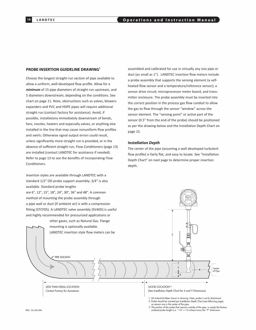
pROBE INSERTION GUIDELINE DRAWING1
Choose the longest straight-run section of pipe available toallow a uniform, well-developed flow profile. Allow for aminimum of 15 pipe diameters of straight run upstream, and5 diameters downstream, depending on the conditions. Seechart on page 11. Note, obstructions such as valves, blowersexpanders and PVC and HDPE pipes will require additionalstraight run (contact factory for assistance). Avoid, ifpossible, installations immediately downstream of bends,fans, nozzles, heaters and especially valves, or anything elseinstalled in the line that may cause nonuniform flow profilesand swirls. Otherwise signal output errors could result,unless significantly more straight run is provided, or in theabsence of sufficient straight run, Flow Conditioners (page 13)are in stalled (contact LANDTEC for assistance if needed).Refer to page 13 to see the benefits of incorporating FlowConditioners.
Insertion styles are available through LANDTEC with astandard 1/2" OD probe support assembly; 3/4" is alsoavailable. Stan dard probe lengths are 6", 12", 15", 18", 24", 30", 36" and 48". A commonmethod of mounting the probe assembly through a pipe wall or duct (if ambient air) is with a compressionfitting (STCF05). A LANDTEC valve assembly (SVA05) is usefuland highly recommended for pressurized applications or
other gases, such as Natural Gas. Flangemounting is optionally available.LANDTEC insertion style flow meters can be
assembled and calibrated for use in virtually any size pipe orduct (as small as 1”). LANDTEC insertion flow meters includea probe assembly that supports the sensing element (a self-heated flow sensor and a tempera ture/reference sensor); asensor drive circuit; micro pro cessor meter board, and trans -mitter enclosure. The probe assembly must be inserted intothe correct position in the pro cess gas flow conduit to allowthe gas to flow through the sensor “window” across thesensor element. The “sensing point” or active part of thesensor (0.5" from the end of the probe) should be positionedas per the drawing below and the Installation Depth Chart onpage 15.
Installation DepthThe center of the pipe (assuming a well developed turbulentflow profile) is fairly flat, and easy to locate. See “InstallationDepth Chart” on next page to determine proper insertiondepth.
Z
Y
X
4" PIPE SHOWN
LESS THAN IDEAL LOCATION Contact Factory for Assistance
GOOD LOCATION2,3 (See Installation Depth Chart for X and Y Dimension)
2. Probe should be inserted per Installation Depth Chart (see following page), so sensors are in the center of the pipe.
3. The portion of the probe that remains outside of the pipe, is simply the factory ordered probe length (i.e. “-15” = 15 inches) minus the “Y” dimension.
Centerof Pipe
ACCU-FLO
84̊ F
13546 SCFM467469670 SCF
88mW
LANDTEC
1. LIA Industrial Meter shown in drawing. Note, probe is not bi-directional.
O p e r a t i o n s a n d I n s t r u c t i o n M a n u a l 15L A N D T E C
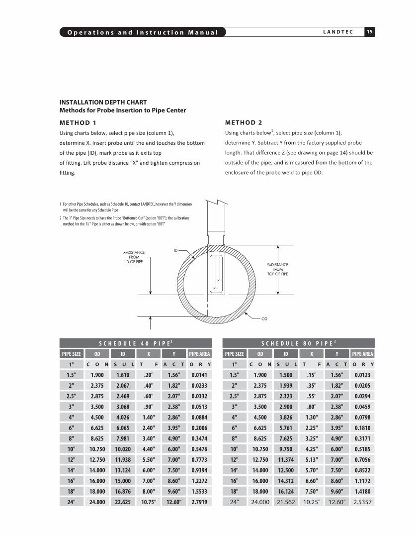
INSTALLATION DEpTH CHARTMethods for probe Insertion to pipe Center
M E T H O D 1Using charts below, select pipe size (column 1),
determine X. Insert probe until the end touches the bottom
of the pipe (ID), mark probe as it exits top
of fitting. Lift probe distance “X” and tighten com pression
fitting.
M E T H O D 2Using charts below1, select pipe size (column 1),
determine Y. Subtract Y from the factory supplied probe
length. That difference Z (see drawing on page 14) should be
outside of the pipe, and is measured from the bottom of the
enclosure of the probe weld to pipe OD.
PIPE SIZE OD ID X Y PIPE AREA
1"
1.5" 1.900 1.500 .15" 1.56" 0.0123
2" 2.375 1.939 .35" 1.82" 0.0205
2.5" 2.875 2.323 .55" 2.07" 0.0294
3" 3.500 2.900 .80" 2.38" 0.0459
4" 4.500 3.826 1.30" 2.86" 0.0798
6" 6.625 5.761 2.25" 3.95" 0.1810
8" 8.625 7.625 3.25" 4.90" 0.3171
10" 10.750 9.750 4.25" 6.00" 0.5185
12" 12.750 11.374 5.13" 7.00" 0.7056
14" 14.000 12.500 5.70" 7.50" 0.8522
16" 16.000 14.312 6.60" 8.60" 1.1172
18" 18.000 16.124 7.50" 9.60" 1.4180
24" 24.000 21.562 10.25" 12.60" 2.5357
S C H E D U L E 4 0 P I P E 2 S C H E D U L E 8 0 P I P E 2
PIPE SIZE OD ID X Y PIPE AREA
1"
1.5" 1.900 1.610 .20" 1.56" 0.0141
2" 2.375 2.067 .40" 1.82" 0.0233
2.5" 2.875 2.469 .60" 2.07" 0.0332
3" 3.500 3.068 .90" 2.38" 0.0513
4" 4.500 4.026 1.40" 2.86" 0.0884
6" 6.625 6.065 2.40" 3.95" 0.2006
8" 8.625 7.981 3.40" 4.90" 0.3474
10" 10.750 10.020 4.40" 6.00" 0.5476
12" 12.750 11.938 5.50" 7.00" 0.7773
14" 14.000 13.124 6.00" 7.50" 0.9394
16" 16.000 15.000 7.00" 8.60" 1.2272
18" 18.000 16.876 8.00" 9.60" 1.5533
24" 24.000 22.625 10.75" 12.60" 2.7919
C O N S U L T F A C T O R Y C O N S U L T F A C T O R Y
1 For other Pipe Schedules, such as Schedule 10, contact LANDTEC, however the Y dimensionwill be the same for any Schedule Pipe
2 The 1" Pipe Size needs to have the Probe “Bottomed Out” (option “BOT"); the calibrationmethod for the 11⁄2 " Pipe is either as shown below, or with option “BOT”

L A N D T E C O p e r a t i o n s a n d I n s t r u c t i o n M a n u a l16
REV. 16-LIA/LRA
84̊ F
13546 SCFM467469670 SCF
88mW
84̊ F
13546 SCFM467469670 SCF
88mW
84̊ F
13546 SCFM467469670 SCF
88mW
84̊ F
13546 SCFM467469670 SCF
88mW
ACCU-FLO
LANDTEC
ACCU-FLO
LANDTEC
ACCU-FLO
LANDTEC
ACCU-FLO
LANDTEC
CONFIGURATION FOR UTILIzING FOUR (4) LANDTEC INSERTION MASS FLOW METERS FOR LARGE ROUND pIpES OR DUCTS LARGER THAN 36" TO MINIMIzE EFFECTS OF VARYING FLOW pROFILES(It is recommended that Factory be contacted to assist with applications of this nature)
The outputs of the four meters will be averaged by customer’s pLC or other method to improveoverall accuracy in measuring the flow rate. (For medium sized round pipes [18" to 36"],two meters, on the opposite side of the samediameter, may be sufficient [insert parallel to anupstream 90 degree bend for optimal benefit.])Note, in this configuration, each sensor needsto be averaged.
1/2" NPTUser Entryfor Wiring
1/2" NPTUser Entryfor Wiring
3/4" NPT forProbe Support
3/4" NPT forRemote Cable3/4" NPT for
Remote Cable
Large Duct or Stack Applications
O p e r a t i o n s a n d I n s t r u c t i o n M a n u a l 17L A N D T E C
REV. 16-LIA/LRA
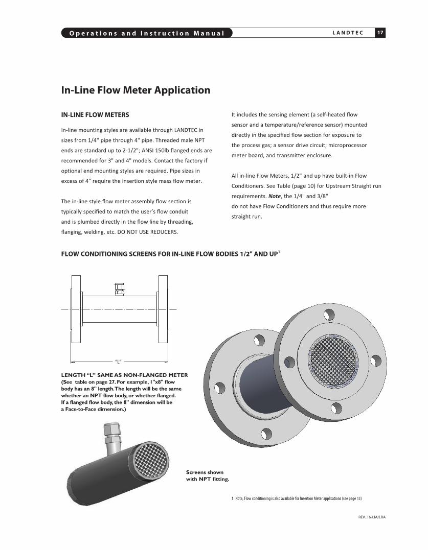
IN-LINE FLOW METERS
In-line mounting styles are available through LANDTEC in
sizes from 1/4" pipe through 4" pipe. Threaded male NPT
ends are standard up to 2-1/2"; ANSI 150lb flanged ends are
recommended for 3" and 4" models. Contact the factory if
optional end mounting styles are required. Pipe sizes in
excess of 4" require the insertion style mass flow meter.
The in-line style flow meter assembly flow section is
typically specified to match the user’s flow conduit
and is plumbed directly in the flow line by threading,
flanging, welding, etc. DO NOT USE REDUCERS.
LENGTH “L” SAME AS NON-FLANGED METER (See table on page 27. For example, 1"x8" flow body has an 8" length. The length will be the samewhether an NPT flow body, or whether flanged. If a flanged flow body, the 8" dimension will be a Face-to-Face dimension.)
FLOW CONDITIONING SCREENS FOR IN-LINE FLOW BODIES 1/2" AND Up1
Screens shown with NPT fitting.
1 Note, Flow conditioning is also available for Insertion Meter applications (see page 13)
It includes the sensing element (a self-heated flow
sensor and a temperature/reference sensor) mounted
directly in the specified flow section for exposure to
the process gas; a sensor drive circuit; microprocessor
meter board, and transmitter enclosure.
All in-line Flow Meters, 1/2" and up have built-in Flow
Conditioners. See Table (page 10) for Upstream Straight run
requirements. Note, the 1/4" and 3/8"
do not have Flow Conditioners and thus require more
straight run.
In-Line Flow Meter Application

L A N D T E C O p e r a t i o n s a n d I n s t r u c t i o n M a n u a l18
REV. 16-LIA/LRA
ACCU-FLO Integral (Series LIA)SEE “WIRING” ON pAGE 10 FOR INSTRUCTIONS ON HOW TO REMOVE REAR LID;SEE FOLLOWING pAGES FOR TERMINAL HOOkUp
1 RED AC1 COM 1
2 S1 AC2 B + 2
3 RED SPARE A – 3
4 WHITE 4-20mA PWR 4
5 S2 4-20mA 5
6 WHITE VDC GND 6
A B C 24 VDCPULSE
VDC IN +
VDC GND –
INTEGRAL
INSIDE COVER VIEW INSIDE BODY VIEW
1/2" NPTUser Entryfor Wiring
3/4" NPT forProbe Support
NO CUSTOMER ACCESSDO NOT OPEN THIS SIDE DISPLAY SIDE
1/2" NPTView Entry
(ONE ON EACH SIDE)
FLOW
TERMINAL BLOCK SIDE

O p e r a t i o n s a n d I n s t r u c t i o n M a n u a l 19L A N D T E C
24 VDC ACCU-FLO Integral Terminals (Series LIA)(AppROVED FOR HAzARDOUS SERVICE6)
1 RED AC1 COM 1
2 S1 AC2 B + 2
3 RED SPARE A – 3
4 WHITE 4-20mA PWR 4
5 S2 4-20mA 5
6 WHITE VDC GND 6
A B C 24 VDCPULSE
VDC IN +
VDC GND –
INTEGRAL
INSIDE COVER VIEW
NOTE: The LANDTEC (ACCU-FLO)draws 2.4 watts maximum (i.e.100ma @24VDC)
– +C U S T O M E RR E T U R N
E X T E R N A L L Y p O W E R E D4 – 2 0 m A B Y C U S T O M E R
+
*
DEsCRIPTION TERMINALs NOTEs
DC Input Power: B5 B6 24 VDC7,8 + VDC – VDC GND
Internally Powered: C5 C6 Do not remove 4-20 mA 4-20 mA Return any Jumpers SIGNAL DRIVE
Internally Powered: C4 C6 Do not remove Pulsed Output GND any Jumpers
Externally Powered: C5 B4 Remove B4 & B5 4-20 mA 4-20 mA 4-20 mA Jumper SIGNAL DRIVE EXtERNAL SOURCE
Externally Powered9: C4 B3 Remove B4 & B5 Pulsed Output JUNCtION fOR Jumper and Connect PULSE REtURN C4 Resistive Jumper to B3
MODBUS C2 C3 C1 Modbus Ground10
RS485(+) RS485(–) MODBUS GROUND (REq’D)
*B4 and B5 JUMPERRemove jumper for Externally sourced 4-20mA. In this mode, user supplies 9-27 Volts toexternally power the 4-20 mA loop, and the 4-20 mA loop becomes optically isolated.
1 Specify the LANDTEC (ACCU-FLO) PLUS option in order to have the Modbus Ground (Terminal C1, COM)isolated from the 24 VDC LANDTEC Power Supply Ground (Terminal B6). All other features of ACCU-FLOPLUS are identical to the standard LANDTEC ACCU-FLO, except other voltage available. (See footnote8)
2 It is important to connect the Ground when using Modbus communications, or ground loop problemsmay develop. Improper wiring can also damage internal circuitry
3 Note, if customer externally powers the 4-20 mA by removing the jumper, the Pulse voltage output is also effected: The voltage output of the Pulse will follow the customer power (i.e. 24 VDC externalpower will result in a 24 VDC Pulse [maximum of 50 mA]; 12 VDC external power will result in a 12 VDC Pulse)
4 Pulse width 250 msec default (adjustable with Addresser software)5 Using LANDTEC Addresser, a Low Flow Cutoff (LFC), commonly referred to as Min Cutoff or Zero Cutoff
can be entered into the FLOw MIN Functions. In Versions 1.82 or higher, the Low Flow Cutoff and the4-20 mA Scaling are independent of each other. For example: A Low Flow Cutoff (LFC) of 10 SCFM on a Meter with a Full Scale of 100 SCFM will report 0 on the Display and 4 mA on the output. The output will remain at 4 mA until the LFC is exceeded: (ie: 25 SCFM=8 mA). Thus the 4 mA will always be zero based
6 Class I, Div 2, Groups B,C,D,T4 and ATEX Ex na IIC T47 24 VDC ±10%8 Other DC voltages (5 VDC, 12 VDC, 48 VDC) available on ACCU-FLO PLUS. Contact LANDTEC9 Assumes the 4-20 mA is Externally Powered
10 Modbus Ground becomes isolated from the B6 Power Supply Ground only on ACCU-FLO PLUS version(specify “PLUS”)
INSIDE BODY VIEW
1/2" NPTUser Entryfor Wiring3/4" NPT for
Remote Cable(on Remote Style LRA)
**
**Note, Flow Meter is supplied with a 10K (1/2watt) metal film resistor (Resistive Jumper)connected across Terminals C4 and C6. Forexternally powered operation, in addition toremoving B4 & B5 Jumpers, it is necessary toconnect C4 Resistive Jumper to Terminal B3instead of C6. Note, B3 must be connected tothe External sources common in order toenable the optically isolated pulse output. Inthis mode, Pulse Output is optically isolated.Pulsed Output voltage will depend oncustomer source voltage. Use LANDTECResistive Jumper only!
**
A1 – RED – VELOCITY SENSOR WIRE (HEATED ELEMENT)A2 – NO WIREA3 – RED – VELOCITY SENSOR WIRE (HEATED ELEMENT)A4 – WHITE – TEMpERATURE SENSOR WIREA5 – NO WIREA6 – WHITE – TEMpERATURE SENSOR WIRE
B3 – JUNCTION FOR ISOLATED pULSEB4 – 4-20 mA RETURN (–) AND pULSE SOURCEB5 – VDC IN – VOLTAGE DC – pOSITIVE (+)B6 – VDC GND – VOLTAGE DC – GROUND (–)1
C1 – COM – RS485 MODBUS GROUND1,2
C2 – B(+)–RS485_D1C3 – A(–)–RS485_D0C4 – 24 VDC pULSE – 0 TO 24 VDC pULSE OUTpUT3,4
C5 – 4-20 mA – 4 TO 20 mA SIGNAL DRIVE5
C6 – VDC GND – VOLTAGE DC – GROUND (–)
24O
24O

L A N D T E C O p e r a t i o n s a n d I n s t r u c t i o n M a n u a l20
AC powered (ACCU-FLO) Integral Terminals (Series LIA)6
1 RED AC1 COM 1
2 S1 AC2 B + 2
3 RED SPARE A – 3
4 WHITE 4-20mA PWR 4
5 S2 4-20mA 5
6 WHITE VDC GND 6
A B C 24 VDCPULSE
VDC IN +
VDC GND –
INTEGRAL
INSIDE COVER VIEW
NOTE: The LANDTEC (ACCU-FLO)draws 2.4 watts maximum (i.e.100ma @24VDC)
– +C U S T O M E RR E T U R N
E X T E R N A L L Y p O W E R E D4 – 2 0 m A B Y C U S T O M E R
+
*B4 and B5 JUMPER Remove jumper forExternally sourced 4-20 mA. In this mode, usersupplies 9-27 Volts to externally power the 4-20 mA loop, and the 4-20 mA loop becomesoptically isolated.
1 Specify the LANDTEC ACCU-FLO PLUS option in order to have the Modbus Ground (Terminal C1, COM)isolated from the 24 VDC LANDTEC Power Supply Ground (Terminal B6). All other features of ACCU-FLOPLUS are identical to the standard LANDTEC ACCU-FLO, except other voltage available. (See footnote 8)
2 It is important to connect the Ground when using Modbus communications, or ground loop problemsmay develop. Improper wiring can also damage internal circuitry
3 Note, if customer externally powers the 4-20 mA by removing the jumper, the Pulse voltage output is also effected: The voltage output of the Pulse will follow the customer power (i.e. 24 VDC externalpower will result in a 24 VDC Pulse [maximum of 50 mA]; 12 VDC external power will result in a 12 VDC Pulse)
4 Pulse width 250 msec default (adjustable with Addresser software)5 Using LANDTEC Addresser, a Low Flow Cutoff (LFC), commonly referred to as Min Cutoff or Zero Cutoff
can be entered into the FLOw MIN Functions. In Versions 1.82 or higher, the Low Flow Cutoff and the4-20 mA Scaling are independent of each other. For example: A Low Flow Cutoff (LFC) of 10 SCFM on a Meter with a Full Scale of 100 SCFM will report 0 on the Display and 4 mA on theoutput. The output will remain at 4 mA until the LFC is exceeded: (ie: 25 SCFM=8 mA). Thus the 4 mA will always be zero based
6 This version does not have Hazard Approvals7 24 VDC ±10%8 Other DC voltages (5 VDC, 12 VDC, 48 VDC) available on ACCU-FLO PLUS. Contact LANDTEC9 Assumes the 4-20 mA is Externally Powered
10 Modbus Ground becomes isolated from the B6 Power Supply Ground only on ACCU-FLO PLUS version(specify “PLUS”)
INSIDE BODY VIEW
1/2" NPTUser Entryfor Wiring
3/4" NPT forRemote Cable
(ON REMOTE STYLE LRA)
GroundingLug
**
**
A1 – RED – VELOCITY SENSOR WIRE (HEATED ELEMENT)A2 – NO WIREA3 – RED – VELOCITY SENSOR WIRE (HEATED ELEMENT)A4 – WHITE – TEMpERATURE SENSOR WIREA5 – NO WIREA6 – WHITE – TEMpERATURE SENSOR WIRE
B1 – AC1 – AC VOLTAGEB2 – AC2 – AC VOLTAGEB3 – JUNCTION FOR ISOLATED pULSEB4 – 4-20 mA RETURN (–) AND pULSE SOURCEB5 – VDC IN – VOLTAGE DC – pOSITIVE (+)B6 – VDC GND – VOLTAGE DC – GROUND (–)1
C1 – COM – RS485 MODBUS GROUND1,2
C2 – B(+)–RS485_D1C3 – A(–)–RS485_D0C4 – 24 VDC pULSE – 0 TO 24 VDC pULSE OUTpUT3,4
C5 – 4-20 mA – 4 TO 20 mA SIGNAL DRIVE5
C6 – VDC GND – VOLTAGE DC – GROUND (–)
24O
24O
DESCRIPtION tERMINALS NOtES
AC Input Power: B1 B2 Connect Ground Wire 115 VAC/230 VAC AC1 AC2 to Grounding Lug
DC Input Power: B5 B6 24 VDC7,8 + VDC – VDC GND
Internally Powered: C5 C6 Do not remove 4-20 mA 4-20 mA Return any Jumpers SIGNAL DRIVE
Internally Powered: C4 C6 Do not remove Pulsed Output GND any Jumpers
Externally Powered: C5 B4 Remove B4 & B5 4-20 mA 4-20 mA 4-20 mA Jumper SIGNAL DRIVE EXtERNAL SOURCE
Externally Powered9: C4 B3 Remove B4 & B5 Pulsed Output JUNCtION fOR Jumper and Connect PULSE REtURN C4 Resistive Jumper to B3
MODBUS C2 C3 C1 Modbus Ground10
RS485(+) RS485(–) MODBUS GROUND (REq’D)
*
**Note, Flow Meter is supplied with a 10K (1/2watt) metal film resistor (Resistive Jumper)connected across Terminals C4 and C6. Forexternally powered operation, in addition toremoving B4 & B5 Jumpers, it is necessary toconnect C4 Resistive Jumper to Terminal B3instead of C6. Note, B3 must be connected tothe External sources common in order toenable the optically isolated pulse output. Inthis mode, Pulse Output is optically isolated.Pulsed Output voltage will depend oncustomer source voltage. Use LANDTECResistive Jumper only!

O p e r a t i o n s a n d I n s t r u c t i o n M a n u a l 21L A N D T E C
REV. 16-LIA/LRA
ACCU-FLO Remote (Series LRA)SEE “WIRING” ON pAGE 10 FOR INSTRUCTIONS ON HOW TO REMOVE REAR LID;SEE FOLLOWING pAGES FOR TERMINAL HOOkUp
REMOTE
1 RED AC1 COM 1
2 GREEN AC2 B + 2
3 BLUE SPARE A – 3
4 WHITE 4-20mA PWR 24 VDC PULSE 4
5 BLACK VDC IN 4-20mA 5
6 ORANGE VDC GND VDC GND 6
A B C1
2
3
4
5
6
1
2
3
4
5
6
A B C
INSIDE COVER VIEW INSIDE BODY VIEW
DISPLAY SIDE
1/2" NPTUser Entryfor Wiring
3/4" NPT forRemote Cable
(ON REMOTE STYLE LRA)
3/4" NPT forRemote Cable
3/4" NPT forProbe Support
Junction Boxcontains noelectronics,just terminals
1/2" NPTUser Entry for Wiring(ONE ON EACH SIDE)
FLOW
TERMINAL BLOCK SIDE
3/4" NPT forRemote Cable
L A N D T E C O p e r a t i o n s a n d I n s t r u c t i o n M a n u a l22
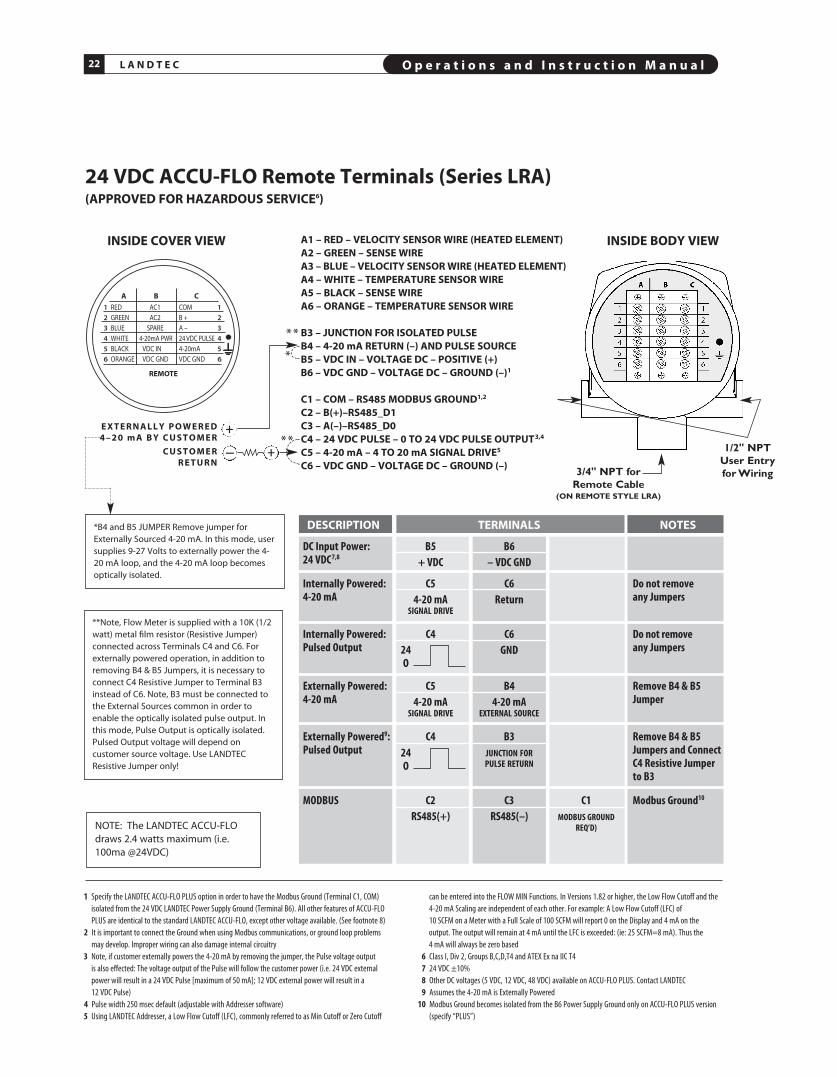
24 VDC ACCU-FLO Remote Terminals (Series LRA)(AppROVED FOR HAzARDOUS SERVICE6)
REMOTE
1 RED AC1 COM 1
2 GREEN AC2 B + 2
3 BLUE SPARE A – 3
4 WHITE 4-20mA PWR 24 VDC PULSE 4
5 BLACK VDC IN 4-20mA 5
6 ORANGE VDC GND VDC GND 6
A B C
A1 – RED – VELOCITY SENSOR WIRE (HEATED ELEMENT)A2 – GREEN – SENSE WIREA3 – BLUE – VELOCITY SENSOR WIRE (HEATED ELEMENT)A4 – WHITE – TEMpERATURE SENSOR WIREA5 – BLACk – SENSE WIREA6 – ORANGE – TEMpERATURE SENSOR WIRE
B3 – JUNCTION FOR ISOLATED pULSEB4 – 4-20 mA RETURN (–) AND pULSE SOURCEB5 – VDC IN – VOLTAGE DC – pOSITIVE (+)B6 – VDC GND – VOLTAGE DC – GROUND (–)1
C1 – COM – RS485 MODBUS GROUND1,2
C2 – B(+)–RS485_D1C3 – A(–)–RS485_D0C4 – 24 VDC pULSE – 0 TO 24 VDC pULSE OUTpUT3,4
C5 – 4-20 mA – 4 TO 20 mA SIGNAL DRIVE5
C6 – VDC GND – VOLTAGE DC – GROUND (–)
INSIDE COVER VIEW
NOTE: The LANDTEC ACCU-FLOdraws 2.4 watts maximum (i.e.100ma @24VDC)
– +C U S T O M E RR E T U R N
E X T E R N A L L Y p O W E R E D4 – 2 0 m A B Y C U S T O M E R
+
*
DESCRIpTION TERMINALS NOTES
DC Input Power: B5 B6 24 VDC7,8 + VDC – VDC GND
Internally Powered: C5 C6 Do not remove 4-20 mA 4-20 mA Return any Jumpers SIGNAL DRIVE
Internally Powered: C4 C6 Do not remove Pulsed Output GND any Jumpers
Externally Powered: C5 B4 Remove B4 & B5 4-20 mA 4-20 mA 4-20 mA Jumper SIGNAL DRIVE EXtERNAL SOURCE
Externally Powered9: C4 B3 Remove B4 & B5 Pulsed Output JUNCtION fOR Jumpers and Connect PULSE REtURN C4 Resistive Jumper to B3
MODBUS C2 C3 C1 Modbus Ground10
RS485(+) RS485(–) MODBUS GROUND REq’D)
*B4 and B5 JUMPER Remove jumper forExternally sourced 4-20 mA. In this mode, usersupplies 9-27 Volts to externally power the 4-20 mA loop, and the 4-20 mA loop becomesoptically isolated.
1 Specify the LANDTEC ACCU-FLO PLUS option in order to have the Modbus Ground (Terminal C1, COM)isolated from the 24 VDC LANDTEC Power Supply Ground (Terminal B6). All other features of ACCU-FLOPLUS are identical to the standard LANDTEC ACCU-FLO, except other voltage available. (See footnote 8)
2 It is important to connect the Ground when using Modbus communications, or ground loop problemsmay develop. Improper wiring can also damage internal circuitry
3 Note, if customer externally powers the 4-20 mA by removing the jumper, the Pulse voltage output is also effected: The voltage output of the Pulse will follow the customer power (i.e. 24 VDC externalpower will result in a 24 VDC Pulse [maximum of 50 mA]; 12 VDC external power will result in a 12 VDC Pulse)
4 Pulse width 250 msec default (adjustable with Addresser software)5 Using LANDTEC Addresser, a Low Flow Cutoff (LFC), commonly referred to as Min Cutoff or Zero Cutoff
can be entered into the FLOw MIN Functions. In Versions 1.82 or higher, the Low Flow Cutoff and the4-20 mA Scaling are independent of each other. For example: A Low Flow Cutoff (LFC) of 10 SCFM on a Meter with a Full Scale of 100 SCFM will report 0 on the Display and 4 mA on the output. The output will remain at 4 mA until the LFC is exceeded: (ie: 25 SCFM=8 mA). Thus the 4 mA will always be zero based
6 Class I, Div 2, Groups B,C,D,T4 and ATEX Ex na IIC T47 24 VDC ±10%8 Other DC voltages (5 VDC, 12 VDC, 48 VDC) available on ACCU-FLO PLUS. Contact LANDTEC9 Assumes the 4-20 mA is Externally Powered
10 Modbus Ground becomes isolated from the B6 Power Supply Ground only on ACCU-FLO PLUS version(specify “PLUS”)
INSIDE BODY VIEW
1/2" NPTUser Entryfor Wiring3/4" NPT for
Remote Cable(ON REMOTE STYLE LRA)
**
**
24O
24O
**Note, Flow Meter is supplied with a 10K (1/2watt) metal film resistor (Resistive Jumper)connected across Terminals C4 and C6. Forexternally powered operation, in addition toremoving B4 & B5 Jumpers, it is necessary toconnect C4 Resistive Jumper to Terminal B3instead of C6. Note, B3 must be connected tothe External sources common in order toenable the optically isolated pulse output. Inthis mode, Pulse Output is optically isolated.Pulsed Output voltage will depend oncustomer source voltage. Use LANDTECResistive Jumper only!

O p e r a t i o n s a n d I n s t r u c t i o n M a n u a l 23L A N D T E C
AC powered ACCU-FLO Remote Terminals (Series LRA)6
REMOTE
1 RED AC1 COM 1
2 GREEN AC2 B + 2
3 BLUE SPARE A – 3
4 WHITE 4-20mA PWR 24 VDC PULSE 4
5 BLACK VDC IN 4-20mA 5
6 ORANGE VDC GND VDC GND 6
A B C
INSIDE COVER VIEW
NOTE: The LANDTEC ACCU-FLO draws 2.4 watts maximum(i.e. 100ma @24VDC)
– +C U S T O M E RR E T U R N
E X T E R N A L L Y p O W E R E D4 – 2 0 m A B Y C U S T O M E R
+
*
DESCRIpTION TERMINALS NOTES
AC Input Power: B1 B2 Connect Ground Wire 115 VAC/230 VAC AC1 AC2 to Grounding Lug
DC Input Power: B5 B6 24 VDC7,8 + VDC – VDC GND
Internally Powered: C5 C6 Do not remove 4-20 mA 4-20 mA Return any Jumpers SIGNAL DRIVE
Internally Powered: C4 C6 Do not remove Pulsed Output GND any Jumpers
Externally Powered: C5 B4 Remove B4 & B5 4-20 mA 4-20 mA 4-20 mA Jumper SIGNAL DRIVE EXtERNAL SOURCE
Externally Powered9: C4 B3 Remove B4 & B5 Pulsed Output JUNCtION fOR Jumpers and Connect PULSE REtURN C4 Resistive Jumper to B3
MODBUS C2 C3 C1 Modbus Ground10
RS485(+) RS485(–) MODBUS GROUND (REq’D)
*B4 and B5 JUMPER Remove jumper forExternally sourced 4-20 mA. In this mode, usersupplies 9-27 Volts to externally power the 4-20 mA loop, and the 4-20 mA loop becomesoptically isolated.
1 Specify the LANDTEC ACCU-FLO PLUS option in order to have the Modbus Ground (Terminal C1, COM)isolated from the 24 VDC LANDTEC Power Supply Ground (Terminal B6). All other features of ACCU-FLOPLUS are identical to the standard LANDTEC ACCU-FLO, except other voltage available. (See footnote8)
2 It is important to connect the Ground when using Modbus communications, or ground loop problemsmay develop. Improper wiring can also damage internal circuitry
3 Note, if customer externally powers the 4-20 mA by removing the jumper, the Pulse voltage output is also effected: The voltage output of the Pulse will follow the customer power (i.e. 24 VDC externalpower will result in a 24 VDC Pulse [maximum of 50 mA]; 12 VDC external power will result in a 12 VDC Pulse)
4 Pulse width 250 msec default (adjustable with Addresser software)5 Using LANDTEC Addresser, a Low Flow Cutoff (LFC), commonly referred to as Min Cutoff or Zero Cutoff
can be entered into the FLOw MIN Functions. In Versions 1.82 or higher, the Low Flow Cutoff and the4-20 mA Scaling are independent of each other. For example: A Low Flow Cutoff (LFC) of 10 SCFM on a Meter with a Full Scale of 100 SCFM will report 0 on the Display and 4 mA on the output. The output will remain at 4 mA until the LFC is exceeded: (ie: 25 SCFM=8 mA). Thus the 4 mA will always be zero based
6 This version does not have Hazard Approvals7 24 VDC ±10%8 Other DC voltages (5 VDC, 12 VDC, 48 VDC) available on ACCU-FLO PLUS. Contact LANDTEC9 Assumes the 4-20 mA is Externally Powered
10 Modbus Ground becomes isolated from the B6 Power Supply Ground only on ACCU-FLO PLUS version(specify “PLUS”)
1
2
3
4
5
6
1
2
3
4
5
6
A B C
INSIDE BODY VIEW
1/2" NPTUser Entryfor Wiring3/4" NPT for
Remote Cable(ON REMOTE STYLE LRA)
GroundingLug
**
**
A1 – RED – VELOCITY SENSOR WIRE (HEATED ELEMENT)A2 – GREEN – SENSE WIREA3 – BLUE – VELOCITY SENSOR WIRE (HEATED ELEMENT)A4 – WHITE – TEMpERATURE SENSOR WIREA5 – BLACk – SENSE WIREA6 – ORANGE – TEMpERATURE SENSOR WIRE
B1 – AC1 – AC VOLTAGEB2 – AC2 – AC VOLTAGEB3 – JUNCTION FOR ISOLATED pULSEB4 – 4-20 mA RETURN (–) AND pULSE SOURCEB5 – VDC IN – VOLTAGE DC – pOSITIVE (+)B6 – VDC GND – VOLTAGE DC – GROUND (–)1
C1 – COM – RS485 MODBUS GROUND1,2
C2 – B(+)–RS485_D1C3 – A(–)–RS485_D0C4 – 24 VDC pULSE – 0 TO 24 VDC pULSE OUTpUT3,4
C5 – 4-20 mA – 4 TO 20 mA SIGNAL DRIVE5
C6 – VDC GND – VOLTAGE DC – GROUND (–)
24O
24O
**Note, Flow Meter is supplied with a 10K (1/2watt) metal film resistor (Resistive Jumper)connected across Terminals C4 and C6. Forexternally powered operation, in addition toremoving B4 & B5 Jumpers, it is necessary to connect C4 Resistive Jumper toTerminal B3 instead of C6. Note, B3 must beconnected to the External sources common inorder to enable the optically isolated pulseoutput. In this mode, Pulse Output is opticallyisolated. Pulsed Output voltage will dependon customer source voltage. Use LANDTECResistive Jumper only!
L A N D T E C O p e r a t i o n s a n d I n s t r u c t i o n M a n u a l24
REV. 16-LIA/LRA
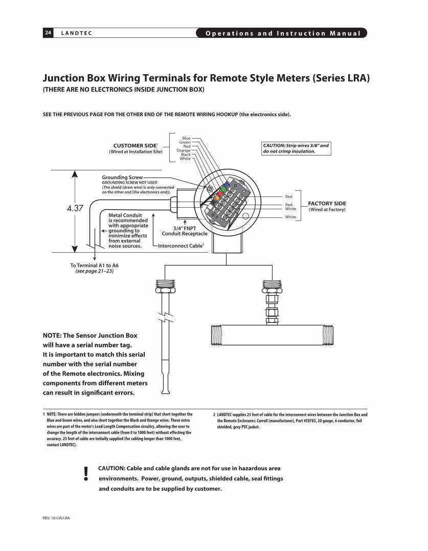
Junction Box Wiring Terminals for Remote Style Meters (Series LRA)(THERE ARE NO ELECTRONICS INSIDE JUNCTION BOX)
CUSTOMER SIDE1
(Wired at Installation Site)
FACTORY SIDE(Wired at Factory)
Red
RedWhite
White
BlueGreen
RedOrange
BlackWhite
CAUTION: Strip wires 3/8" and do not crimp insulation.
4.37
3/4” FNPTConduit Receptacle
Grounding ScrewGROUNDING SCREW NOT USED (The shield [drain wire] is only connected on the other end [the electronics end]).
Metal Conduit is recommended with appropriate grounding to minimize effects from external noise sources. Interconnect Cable2
To Terminal A1 to A6(see page 21–23)
SEE THE pREVIOUS pAGE FOR THE OTHER END OF THE REMOTE WIRING HOOkUp (the electronics side).
NOTE: The Sensor Junction Box will have a serial number tag. It is important to match this serialnumber with the serial number of the Remote electronics. Mixingcomponents from different meterscan result in significant errors.
! CAUTION: Cable and cable glands are not for use in hazardous area
environments. power, ground, outputs, shielded cable, seal fittings
and conduits are to be supplied by customer.
1 NOtE: there are hidden jumpers (underneath the terminal strip) that short together theBlue and Green wires, and also short together the Black and Orange wires. these extrawires are part of the meter's Lead Length Compensation circuitry, allowing the user tochange the length of the interconnect cable (from 0 to 1000 feet) without effecting theaccuracy. 25 feet of cable are initially supplied (for cabling longer than 1000 feet,contact LANDtEC).
2 LANDtEC supplies 25 feet of cable for the interconnect wires between the Junction Box andthe Remote Enclosures: Carroll (manufacturer), Part #C0783, 20 gauge, 6 conductor, foilshielded, grey PVC jacket.

Section
STYLES AND FEATURES
B


O p e r a t i o n s a n d I n s t r u c t i o n M a n u a l 27L A N D T E C
REV. 16-LIA/LRA
LANDTEC Thermal Mass Flow Meters have two sensors
constructed of reference grade platinum windings (RTDs).
The two RTDs are clad in a protective 316SS sheath and are
driven by a proprietary sensor drive circuit. One of the
sensors is self-heated (flow sensor), and the other sensor
(temperature/reference sensor) measures the gas
temperature. The pair is referred to as the sensing element,
and is either installed in a probe as an Insertion style, or
inserted into a pipe section as an In-Line style flow meter.
As gas flows by the flow sensor, the gas molecules carry heat
away from the surface, and the sensor cools down as it loses
energy. The sensor drive circuit replenishes the lost energy
by heating the flow sensor until it is a constant temperature
differential above the reference sensor. The electrical power
required to maintain a constant temperature differential is
directly proportional to the gas mass flow rate and is
linearized to be the output signal of the meter.
principle of Operation of the Thermal Mass Flow Meter
It is essential that this constant temperature differ ential be
maintained, even if there are wide fluctuations in gas
temperature. It is the function of the LANDTEC hybrid-digital
proprietary sensor drive circuit to maintain the differential,
whether or not the gas temperature changes, or however
quickly molecules cool off the flow sensor. It is also
necessary to properly calibrate the device with the actual gas
(or close equivalent with certain gases), in the LANDTEC
National Institute of Standards certified (NIST) calibration
facility. By accomplishing these two critical objectives, the
LANDTEC meters provide an extremely repeatable (0.2% of
Full Scale) and accurate output directly proportional to the
mass flow rate of the gas being measured.
FLOW SENSOR(Self Heated)
TEMPERATURE SENSOR(Reference Sensor)

L A N D T E C O p e r a t i o n s a n d I n s t r u c t i o n M a n u a l28
REV. 16-LIA/LRA
Features and Benefits
MAJOR BENEFITS OF THERMAL MASS FLOW METERSn Direct Mass Flow – No need for separate temperature or pressure
transmittersn High Accuracy and Repeatability – Precision measurement and
extraordinary repeatabilityn Turndown of 100 to 1 and resolution as much as 1000 to 1n Low-End sensitivity – Measures as low as 5 sFPM (e.g., 1 sCFM
in a 6" pipe)n Negligible Pressure Drop – Will not impede the flow or waste energyn No Moving Parts – Eliminates costly bearing replacements, and
prevents undetected accuracy shiftsn Dirt Insensitive – Provides sustained performancen Low cost-of-ownershipn Ease of installation and convenient mounting hardware
SpECIFIC BENEFITS OF THE LANDTEC ACCU-FLOn Features In-situ “Field Zero Calibration Check” of sensor’s
performance – verifies that the sensor is clean, and assures that thereis no drift, or shift in the flow meter
n Compact design of enclosure is only 41⁄8" dia. by 41⁄4" deep (DCModels)
n High contrast photo-emissive OLED display with numerical FlowRate, Total and Temperature, as well as Graphical Flow Indicator
n Calibration milliwatts (mW) is continuously displayed, providing forongoing diagnostics
n Photocell activated screen saver to extend display life2
n Proprietary digital sensor drive circuit provides enhanced signalstability and unaffected by process temperature & pressure changes
n Modbus compliant Rs485 RTU communicationsn HART™ communications (optional)n Isolated 4-20 mA output and pulsed output of Totalized Flown Rugged, user-friendly packaging with easy terminal accessn Option for solar Energy use (12VDC models)n Remote style has Lead-Length Compensation. Allows remote
electronicsup to 1000 feet from probe; Explosion Proof Junction Boxhas no circuitry, just terminals (suitable for harsh environments)
n Low power dissipation, under 2.5 Watts (e.g. under 100 ma at 24VDC)
n Field reconfigurability via HART or optional Addresser softwaren Flow conditioning built into In-Line flow meters (1/2" and up)n Captive Flow Conditioners for Insertion meter applications, if
required
LANDTEC ACCU-FLO THERMAL MASS FLOW METER FORGASESLANDTEC ACCU-FLO is the top selling meter in our Product Line. TheLANDTEC ACCU-FLO Thermal Mass Flow Meter features a bright,high contrast, photo-emissive OLED display of Flow Rate, Total andTemper ature in a robust, yet lightweight, dual-compartmentindustrial enclosure. The flow rate is also displayed graphically in ahorizontal bar graph format. The rear compartment is completelyseparated from the electronics, and has large, easy-to-access, wellmarked terminals, for ease of customer wiring (see photo below). Itis powered by 24 VDC (12 VDC optional, or 115/230 VAC). The powerdissipation is under 2.5 watts (e.g. under 100 mA at 24 VDC).
The LANDTEC ACCU-FLO Flow Meter is offered in Integral orRemote style (which has lead-length compensation up to 1000 feetas well as an Explosion Proof Junction Box). specify any standardprobe length or flow body size. It has a 4-20 mA output as well as aPulsed Output of Totalized Flow (solid state transistor drive). Inaddition, LANDTEC ACCU-FLO supports full Modbus® compliantRs485 RTU communi cations (IEEE 32 Bit Floating Point).
LANDTEC ACCU-FLO is CE approved, CsA and UL approved forHazardous service2 (see Approvals tab on the website).
CONTINUOUS DIAGNOSTICS & FIELD CONFIGURABILITYLANDTEC ACCU-FLO has continuous diagnostics. The rawcalibration milliwatts (mw) is always displayed in the upper lefthand corner of the meter’s display. At any time, you can check thisreading at a “no flow” condition, and compare the reading to theoriginal re ported “zero flow” value noted on the last few lines ofyour meter’s Certificate of Con formance or the flow meter’s datatag. This in-situ diagnostic pro cedure not only checks the sensorperformance and the “live zero” calibration point, but it also verifiesthat the sensor is clean. It essentially provides a means to validatethat the meter is oper ating properly, verifies that there is no shift ordrift, and eliminates the need for annual fac tory calibrations. Thissimple field diagnostic procedure, in addition, verifies that the
sensor is free from contamination, even withoutinspection.
Although LANDTEC ACCU-FLO is fullyconfigured upon shipment, for the pipe andprocess con ditions requested, if changes
are needed, Addresser software isoptionally available for field
reconfigurability.1 Only available with 24VDC powered meters2 Note, a built-in photocell continuously monitors the ambient light, and adjusts the displaybrightness for optimum long-term life, and also senses motion which automatically switchesdisplay from Screen Saver mode to Normal mode
O p e r a t i o n s a n d I n s t r u c t i o n M a n u a l 29L A N D T E C
REV. 16-LIA/LRA
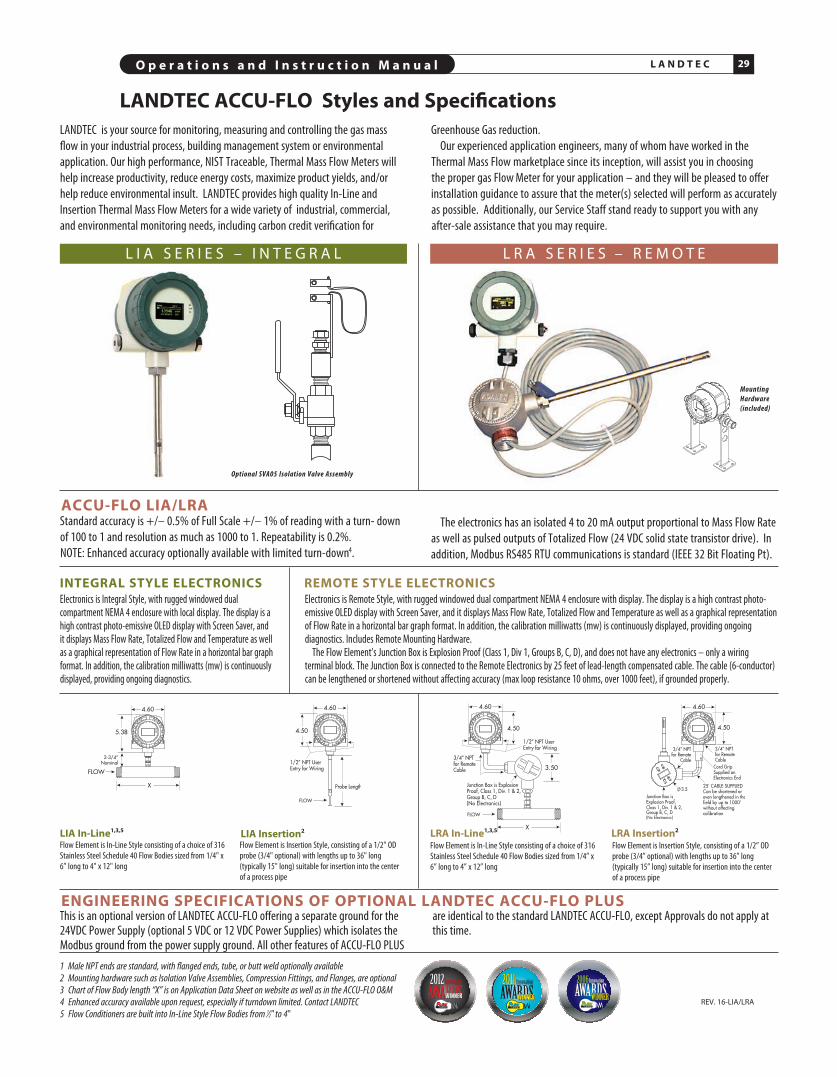
LANDTEC ACCU-FLO Styles and Specifications
L I A s E R I E s – I N T E G R A L
Mounting Hardware (included)
Flow Element is In-Line Style consisting of a choice of 316Stainless Steel Schedule 40 Flow Bodies sized from 1/4” x6” long to 4” x 12” long
Flow Element is Insertion Style, consisting of a 1/2” ODprobe (3/4” optional) with lengths up to 36” long (typically 15” long) suitable for insertion into the center of a process pipe
Electronics is Remote Style, with rugged windowed dual compartment NEMA 4 enclosure with display. The display is a high contrast photo-emissive OLED display with Screen Saver, and it displays Mass Flow Rate, Totalized Flow and Temperature as well as a graphical representationof Flow Rate in a horizontal bar graph format. In addition, the calibration milliwatts (mw) is continuously displayed, providing ongoingdiagnostics. Includes Remote Mounting Hardware. The Flow Element’s Junction Box is Explosion Proof (Class 1, Div 1, Groups B, C, D), and does not have any electronics – only a wiring
terminal block. The Junction Box is connected to the Remote Electronics by 25 feet of lead-length compensated cable. The cable (6-conductor)can be lengthened or shortened without affecting accuracy (max loop resistance 10 ohms, over 1000 feet), if grounded properly.
REMOTE STYLE ELECTRONICS
XLRA In-Line1,3,5 LRA Insertion2
ENGINEERING SpECIFICATIONS OF OpTIONAL LANDTEC ACCU-FLO pLUSThis is an optional version of LANDTEC ACCU-FLO offering a separate ground for the24VDC Power Supply (optional 5 VDC or 12 VDC Power Supplies) which isolates theModbus ground from the power supply ground. All other features of ACCU-FLO PLUS
are identical to the standard LANDTEC ACCU-FLO, except Approvals do not apply atthis time.
Flow Element is In-Line Style consisting of a choice of 316Stainless Steel Schedule 40 Flow Bodies sized from 1/4" x6” long to 4" x 12" long
Flow Element is Insertion Style, consisting of a 1/2" ODprobe (3/4" optional) with lengths up to 36" long (typically 15" long) suitable for insertion into the center of a process pipe
INTEGRAL STYLE ELECTRONICSElectronics is Integral Style, with rugged windowed dualcompartment NEMA 4 enclosure with local display. The display is ahigh contrast photo-emissive OLED display with Screen Saver, andit displays Mass Flow Rate, Totalized Flow and Temperature as wellas a graphical representation of Flow Rate in a horizontal bar graphformat. In addition, the calibration milliwatts (mw) is continuouslydisplayed, providing ongoing diagnostics.
X
LIA In-Line1,3,5 LIA Insertion2
1 Male NPT ends are standard, with flanged ends, tube, or butt weld optionally available2 Mounting hardware such as Isolation Valve Assemblies, Compression Fittings, and Flanges, are optional3 Chart of Flow Body length “X” is on Application Data Sheet on website as well as in the ACCU-FLO O&M4 Enhanced accuracy available upon request, especially if turndown limited. Contact LANDTEC5 Flow Conditioners are built into In-Line Style Flow Bodies from 1⁄2" to 4"
LANDTEC is your source for monitoring, measuring and controlling the gas massflow in your industrial process, building management system or environmentalapplication. Our high performance, NIST Traceable, Thermal Mass Flow Meters willhelp in crease productivity, reduce energy costs, maximize product yields, and/orhelp reduce environmental insult. LANDTEC provides high quality In-Line andInsertion Thermal Mass Flow Meters for a wide variety of industrial, commercial,and environmental monitoring needs, including carbon credit verification for
Greenhouse Gas reduction.Our experienced application engineers, many of whom have worked in the
Thermal Mass Flow marketplace since its inception, will assist you in choosing the proper gas Flow Meter for your application – and they will be pleased to offerinstallation guidance to assure that the meter(s) selected will perform as accuratelyas possible. Additionally, our Service Staff stand ready to support you with anyafter-sale assistance that you may require.
L R A s E R I E s – R E M O T E
ACCU-FLO LIA/LRAStandard accuracy is +/– 0.5% of Full Scale +/– 1% of reading with a turn- downof 100 to 1 and resolution as much as 1000 to 1. Repeatability is 0.2%. NOTE: Enhanced accuracy optionally available with limited turn-down4.
The electronics has an isolated 4 to 20 mA output proportional to Mass Flow Rateas well as pulsed outputs of Totalized Flow (24 VDC solid state transistor drive). Inaddition, Modbus RS485 RTU communications is standard (IEEE 32 Bit Floating Pt).
Optional SVA05 Isolation Valve Assembly
®®

L A N D T E C O p e r a t i o n s a n d I n s t r u c t i o n M a n u a l30
REV. 16-LIA/LRA
1 Upon start-up, the Revision No., Serial No., and Modbus ID will display for a fewseconds. Also the output configurations symbol is momentarily displayed
2 Note, a built-in photocell continuously monitors the ambient light, and adjusts thedisplay brightness for optimum long-term life, and also senses motion whichautomatically switches display from Screen Saver mode to Normal mode
3 to view display, wave hand over display or use a flashlight. the flow Meter displaysfor one minute, then the Screen Saver resumes
1 Raw Calibration milliwatts (mw) for Diagnostics and Periodic “Zero Flow” Calibration Check
2 Graphical Indication of Percentage of Full Scale Flow Rate
3 Flow Rate
4 Totalized Flow (Consumption)(Value is Retained during Power Outage or Power Cycling)
5 Flashes with each pulsed output of consumption
6 Engineering Units of Flow Rate (the last digit can be S(seconds), M(minute), H(hour), D(day)
7 Engineering Units of Consumption
8 Photocell activated Screen Saver extends display life
COMM
PWR
...˚
ACCU-FLO
LANDTEC1
2
3
4
5
67
LANDTEC ACCU-FLO Organic (OLED) Display1,2,3
8
O p e r a t i o n s a n d I n s t r u c t i o n M a n u a l 31L A N D T E C
REV. 16-LIA/LRA
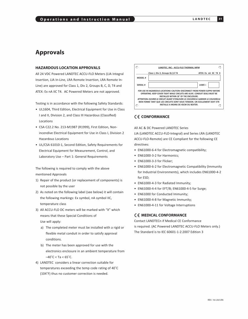
HAzARDOUS LOCATION AppROVALSAll 24 VDC Powered LANDTEC ACCU-FLO Meters (LIA Integral
Insertion, LIA In-Line, LRA Remote Insertion, LRA Remote In-
Line) are approved for Class 1, Div 2, Groups B, C, D, T4 and
ATEX: Ex nA IIC T4. AC Powered Meters are not approved.
Testing is in accordance with the following Safety Standards:
• UL1604, Third Edition, Electrical Equipment for Use in Class
I and II, Division 2, and Class III Hazardous (Classified)
Locations
• CSA C22.2 No. 213-M1987 (R1999), First Edition, Non-
incendive Electrical Equipment for Use in Class I, Division 2
Hazardous Locations
• UL/CSA 61010-1, Second Edition, Safety Require ments for
Electrical Equipment for Measurement, Control, and
Laboratory Use – Part 1: General Requirements
The following is required to comply with the above
mentioned Approvals
1) Repair of the product (or replacement of components) is
not possible by the user
2) As noted on the following label (see below) it will contain
the following markings: Ex symbol, nA symbol IIC,
temperature class
3) All ACCU-FLO DC meters will be marked with “X” which
means that these Special Conditions of
Use will apply:
a) The completed meter must be installed with a rigid or
flexible metal conduit in order to satisfy approval
conditions.
b) The meter has been approved for use with the
electronics enclosure in an ambient temperature from
–40˚C < Ta < 65˚C. 4) LANDTEC considers a linear correction suitable for
temperatures exceeding the temp code rating of 40˚C(104˚F) thus no customer correction is needed.
CONFORMANCE
All AC & DC Powered LANDTEC SeriesLIA (LANDTEC ACCU-FLO-Integral) and Series LRA (LANDTECACCU-FLO-Remote) are CE Compliant for the following CEdirectives:• EN61000-6-4 for Electromagnetic compatibility;• EN61000-3-2 for Harmonics;• EN61000-3-3 for Flicker;• EN61000-6-2 for Electromagnetic Compatibility (Immunity
for Industrial Environments), which includes EN61000-4-2for ESD;
• EN61000-4-3 for Radiated Immunity;• EN61000-4-4 for EFT/B; EN61000-4-5 for Surge;• EN61000 for Conducted Immunity;• EN61000-4-8 for Magnetic Immunity;• EN61000-4-11 for Voltage Interruptions
MEDICAL CONFORMANCEContact LANDTECn if Medical CE Conformance is required. (AC Powered LANDTEC ACCU-FLO Meters only.)The Standard is to IEC 60601-1-2:2007 Edition 3
Approvals
LANDTEC, INC.- ACCU-FLO THERMAL MFM
Class I, Div 2, Groups B,C,D T4 ATEX: Ex nA IIC T4 X
MODEL #
SERIAL # mW0 =
FOR USE IN HAZARDOUS LOCATIONS–CAUTION–DISCONNECT FROM POWER SUPPLY BEFOREOPERATING. KEEP COVER TIGHT WHILE CIRCUITS ARE ALIVE. CONDUIT SEALS MUST BE
INSTALLED WITHIN 18˚ OF THE ENCLOSURE.ATTENTION–OUVRIR LE CIRCUIT AVANT D’ENLEVER LE COUVERCLE GARDER LE COUVERCLE
BIEN FERME TANT QUE LES CIRCUITS SONT SOUS TENSION. UN SCELLEMENT DOIT ETRINSTALLE A MOINS DE 45CM DU BOITER.


Section
DRAWINGS
C


O p e r a t i o n s a n d I n s t r u c t i o n M a n u a l 35L A N D T E C
REV. 16-LIA/LRA
INSERTION STYLE2
150#, 300#, or 600# flanged mounting is optionally available.Available probe lengths are 6", 12", 15", 18", 24", 30", 36" or 48".Standard probe is 1/2" diameter (3/4" optional – recommended for36" or 48")
4.50
4.60
Probe Length
FLOW
LIA Series Integral Style Mass Flow Meters
IN-LINE STYLE1,3
150#, 300#, or 600# flanged ends are optionally available. (150#flanges recommended on 3" and 4" Flow Bodies)
5.38
2-3/4” Nominal
See Chart
FLOW
4.61
1 NPt fittings standard2 flanged Mounting available for high pressure operation3 flow Conditioning built in to flow Meter Pipe Sizes 1/2" and up. Contact LANDtEC for
optional 1/4" tube flow body.
Depth: DC Enclosure depth is 4.35" AC Enclosure depth is 5.35"
1/2" NPT User Entryfor Wiring
1/2" NPT User Entryfor Wiring
CAUTION: Do not rotate theEnclosure of In-LineStyle Meters relativeto the Flow Tube, orthe calibration maybe effected since thesensors may becomemisaligned.
L A N D T E C O p e r a t i o n s a n d I n s t r u c t i o n M a n u a l36
REV. 16-LIA/LRA
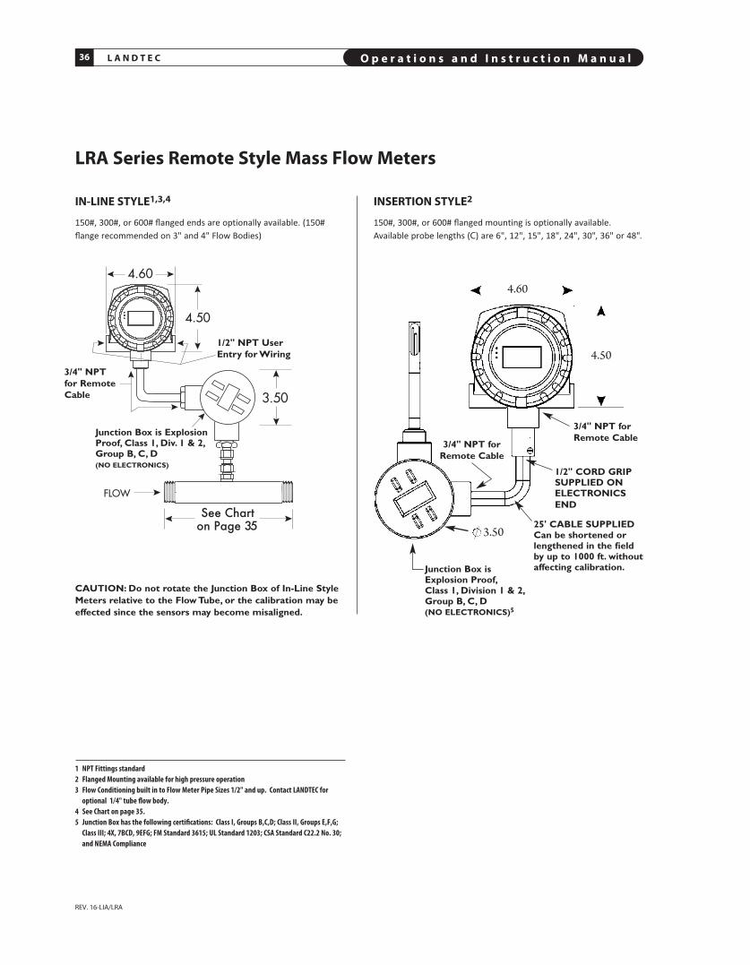
LRA Series Remote Style Mass Flow Meters
INSERTION STYLE2
150#, 300#, or 600# flanged mounting is optionally available.Available probe lengths (C) are 6", 12", 15", 18", 24", 30", 36" or 48".
See Charton Page 35
IN-LINE STYLE1,3,4
150#, 300#, or 600# flanged ends are optionally available. (150#flange recommended on 3" and 4" Flow Bodies)
1 NPt fittings standard2 flanged Mounting available for high pressure operation3 flow Conditioning built in to flow Meter Pipe Sizes 1/2" and up. Contact LANDtEC for
optional 1/4" tube flow body.4 See Chart on page 35.5 Junction Box has the following certifications: Class I, Groups B,C,D; Class II, Groups E,f,G;
Class III; 4X, 7BCD, 9EfG; fM Standard 3615; UL Standard 1203; CSA Standard C22.2 No. 30;and NEMA Compliance
4.60
4.50
3.50
Junction Box is ExplosionProof, Class 1, Div. 1 & 2,Group B, C, D(NO ELECTRONICS)
3/4" NPT for RemoteCable
1/2" NPT UserEntry for Wiring
3/4" NPT forRemote Cable
3/4" NPT forRemote Cable
1/2" CORD GRIPSUPPLIED ONELECTRONICSEND
25' CABLE SUPPLIEDCan be shortened orlengthened in the fieldby up to 1000 ft. withoutaffecting calibration.Junction Box is
Explosion Proof,Class 1, Division 1 & 2,Group B, C, D(NO ELECTRONICS)5
CAUTION: Do not rotate the Junction Box of In-Line StyleMeters relative to the Flow Tube, or the calibration may beeffected since the sensors may become misaligned.

O p e r a t i o n s a n d I n s t r u c t i o n M a n u a l 37L A N D T E C
REV. 16-LIA/LRA
LANDTEC ACCU-FLO Remote Bracket Layout
MOUNTING OpTIONS1. Overhead with U-bolts (customer supplied) across pipe on
each leg
2. Vertically, as shown
3. Horizontally
4.61
7.38
2.00
CORD GRIP orNPT PLUG (as req’d)
BOTH SIDES
WAVEWASHER
WAVEWASHER
.266 DIAHOLES
1/2" NPT User Entryfor Wiring (2)
3/4" NPT forRemote Cable
1/2" NPT User Entryfor Wiring (2)

L A N D T E C O p e r a t i o n s a n d I n s t r u c t i o n M a n u a l38
REV. 16-LIA/LRA
11.00
Mounting Hardware3
STCF SERIES TEFLON FERRULE COMpRESSION FITTING
1/2" tube x 1/2" pipe fitting (shown, not to scale), is used forlow pressure insertion applications to 125 psig (StainlessSteel Ferrule optional for higher pressure applications – up to225 psig). Also available in 3/4" tube x 3/4" pipe size.
1.92
1 At 250 psig, force exerted on 1/2" diameter probe is 50 lbs2 Safety chain is designed to prevent probe from accidentally escaping from assembly during removal from
pressurized pipe3 Insertion meters can have optional flanged mounting (generally used for high pressure or very hot gases). this
adaptation is not shown. Consult factory for details.4 Maximum gas temperature, 200f, unless high temperature models ordered.5 Hot tapping is feasible by removing Weldment (upper portion of assembly temporarily removed)6 See page 46. SVA05 can be utilized for Sensor functionality and Zero Self Check.7 the allen wrench for SVA05 is 9⁄64 (it is 3⁄16 for SVA07).
1/2" BORE SINGLE PIECECOLLAR CLAMPS7
3/4"x1.5" PIPE NIPPLES3/4"x3" BALL VALVE
SVA05 SERIES ISOLATION VALVE ASSEMBLY DETAIL5,6
Cut away view of probe inserted through isolation ball valve assembly.
1/2"–3/4" BALL VALVE WELDMENT WITH 1/2" TUBE TO PIPE COMPRESSION FITTING
3/4"x1" HALF COUPLING(THREADOLET)
MOUNTING pLATE FOR THIN WALLED DUCTS(INCLUDES STCF05 COMpRESSION FITTING)
4"
4"
NOtE: User needs to weld a 3/4" female threadolet (ofappropriate radius) to mate with existing pipe after a 3/4" holehas been drilled in pipe. the 3/4" Male Coupling of the LANDtECIsolation Valve Assembly will thread into the user’s 3/4"threadolet.
SAFETY CHAIN
PROBE LENGtH SAfEtY (with sensor) 2CHAIN LENGtH2
12" 8.25" 15" 11.25" 18" 14.25" 24" 20.25"
SVA05 SERIES ISOLATION VALVE ASSEMBLY FOR INSERTION METERS4
(for Low Pressure sVA05 see page 39)
Used for pressures to 250 psig1 (shown for use with 1/2"diameter insertion meters). 150# or 300# flanged mountingis op tionally available. Available sizes are 1/2" x 3/4" NPT(SVA05 shown), and 3/4" x 1" NPT for use with 3/4" diameterinsertion meters (SVA07).
SENSOR ASSEMBLYEXTENDS 2.25" L
BELOW THELOWER EDGE OF
THE WELDED COLLAR CLAMP
WITH CHAIN TAUT
3/4" THREADOLET(User Supplied)
O p e r a t i o n s a n d I n s t r u c t i o n M a n u a l 39L A N D T E C
REV. 16-LIA/LRA
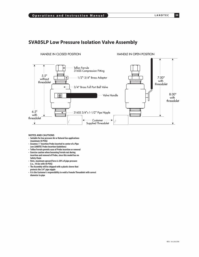
Teflon Ferrule 316SS Compression Fitting
316SS 3/4"x 1-1/2" Pipe Nipple
8.00"with
threadolet
7.00"with
threadolet
HANDLE IN CLOSED POSITION HANDLE IN OPEN POSITION
3/4" Brass Full Port Ball Valve
1/2"-3/4" Brass Adaptor5.5"
withoutthreadolet
6.5"with
threadolet
Valve Handle
CustomerSupplied Threadolet
SVA05Lp Low pressure Isolation Valve Assembly
NOTES AND CAUTIONS• Suitable for low pressure Air or Natural Gas applications
(maximum 50 PSIG)• Assumes 1⁄2" Insertion Probe inserted to center of a Pipe
(see LANDtEC Probe Insertion Guidelines)• teflon ferrule permits ease of Probe insertion or removal• Exercise caution when loosening ferrule nut during
insertion and removal of Probe, since this model has no Safety Chain
• Note, maximum upward force is 20% of pipe pressure (i.e., 10 Lbs with 50 PSIG)
• the Assembly will be shipped with a plastic sleeve that protects the 3/4" pipe nipple
• It is the Customer’s responsibility to weld a female threadolet with correctdiameter to pipe

UPSTREA
M
FLOW
L A N D T E C O p e r a t i o n s a n d I n s t r u c t i o n M a n u a l40
REV. 16-LIA/LRA
Flanged Ends for In-Line Meter (OpTIONAL)
Flanges for 31⁄2" pipe sizes and up, have 8 bolt holes
Flanges for 3" pipe sizes and smaller have 4 bolt holes
Flanged Mounting for Insertion Meter (OpTIONAL)

Section
DIAGNOSTICS
D

O p e r a t i o n s a n d I n s t r u c t i o n M a n u a l 43L A N D T E C
Common DiagnosticsSYMpTOM: Display failure, or pixels extremely dim.CORRECTIVE ACTION: Contact Factory. Certain types offailures are under long term warranty. Please note that the4-20 mA will still function normally.
SYMpTOM: Display fading, or partially fading.CORRECTIVE ACTION: a) Some fading, particularly with those characters that are lit
up most frequently, is normal. The flow meter willcontinue to function properly, and flow meter accuracyand outputs will not be effected.
b) In extreme cases, contact the factory for displayreplacement.
c) Note, in late 2009, the LANDTEC ACCU-FLO was modified to incorporate a built-in photocell. The purpose of thephotocell is to adjust the display brightness with ambientlighting. The brighter the surrounding lighting conditions,the brighter the display. Lower ambient lightingconditions, such as a factory environment, will dim thedisplay. The display will be dimmest if operated in lowambient lighting, or at night. The photocell circuit isdesigned to extend the life of the display, and tominimize fading.
d) Note, in early 2010, a further enhancement was added tofurther extend the life of the display. The abovementioned built-in photocell also senses motion which automatically switches display fromScreen Saver mode to Normal mode.
SYMpTOM: Erratic Readings.pOSSIBLE CAUSES: If a large Motor or Generator orVariable Fre quen cy Drive (VFD) is nearby the enclosure, itmay be inducing sufficient analog noise into the circuitry totemporarily corrupt the data. SUGGESTED CORRECTIVE ACTION: a) If a Power-Restart temporarily solves the problem, than it
is likely that the source of the noise was the problem.
b) To prevent subsequent problems, if a Remote Style Meter, move the enclosure as far away as possiblefrom the source (the Motor or VFD).
c) If an Integral Style Meter, mount the meter in a different location (further from the source) or move thesource further from the meter.
SYMpTOM: Erratic Readings on a Remote Meter.pOSSIBLE CAUSE: In some cases, analog noise is inducedinto the Remote cable causing erratic, or climbing readings.SUGGESTED CORRECTIVE ACTION:a) Be sure the remote cable is installed in metal conduit and
grounded on one end (in some cases, grounding bothends may be required).
b) Also, avoid coiled cable, especially if not in metal conduit.
c) Also, if extra cable exists, move the extra cable as faraway as possible from any source of analog noise, such aslarge motors or VFDs.
SYMpTOM: Meter reading zero continuously, or Full Scalecontinuously, or temperature reading is abnormally low(hundreds of degrees below zero).pOSSIBLE CAUSES/SUGGESTED CORRECTIVE ACTION: a) It is likely that a wire is loose. But in rare cases,
a sensor could fail (i.e., if a standard sensor, HT01 or HT02sensor exceeds a process temperature of 450˚F.)
b) Check for continuity to be sure the wiring is making good contact at the terminals of the Junction Box.
c) Also, to verify that the electronics and the sensor serialnumber are the same, note the following: The sensor’sserial number will come up upon power up, right afterInitializing on the Display. If the serial number doesn'tagree with the Junction Box labels, that would affect cali -bration (in other words, sensors and electronics are amatched pair—mixing them up will cause false readings).Also metal Serial Number Tags are fastened to both theelectronics and the Junction Box. They must have identicalSerial numbers.
d) To check if a sensor has failed on a remote style meter, itis easy to use the Junction Box to do so. You must PowerDown (shut off power), but you do not need to removethe probe from the pipe. Refer to page 24.
e) An Ohm Meter is required to check across the sensorleads of the Flow Sensor. Look at the drawing of theJunction Box. Disconnect the red wires on the Factory Sideto isolate and measure the resistance. If the reading isinfinity or a short, it means that sensor has failed.
f) Now check the Temperature Sensor. Disconnect the whitewires on the Factory Side to isolate and measure theresistance. If you have infinity or a short, it means thatsensor is burned out. Note: Normally the sensors will readapproximately 110 ohms at 70˚ F. At higher temperaturesthey should read a higher resistance, but both sensorsshould have a similar value.
g) On integral style meters (LIA), there is no Junction Box. Inthat case, refer to the ACCU-FLO Integral Terminals onpage 19 and check the sensor wires. Remove the appro -priate wires first (red pair for flow, then white pair fortemperature). Measure their resistance. If reading infinityor short, it means that sensor has failed.
SYMpTOM: Meter Railing (Pegging) or Reading HighpOSSIBLE CAUSES/SUGGESTED CORRECTIVE ACTION: a) Insufficient straight run (i.e. flow profile is disturbed,
causing errors).
b) Possible jet effect if upstream pipe is smaller than meterflow body or if valve is too close upstream to meter.
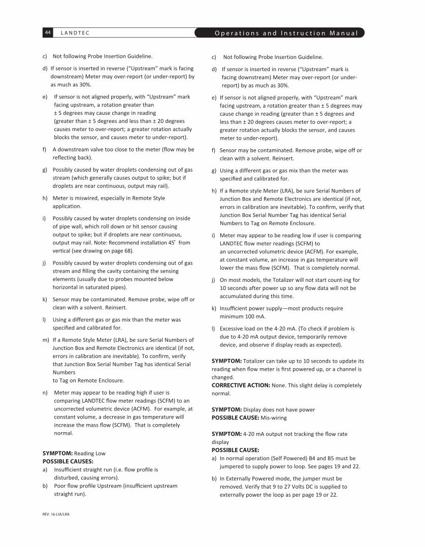
L A N D T E C O p e r a t i o n s a n d I n s t r u c t i o n M a n u a l44
REV. 16-LIA/LRA
c) Not following Probe Insertion Guideline.
d) If sensor is inserted in reverse (“Upstream” mark is facingdownstream) Meter may over-report (or under-report) byas much as 30%.
e) If sensor is not aligned properly, with “Upstream” markfacing upstream, a rotation greater than ± 5 degrees may cause change in reading (greater than ± 5 degrees and less than ± 20 degreescauses meter to over-report; a greater rotation actuallyblocks the sensor, and causes meter to under-report).
f) A downstream valve too close to the meter (flow may bereflecting back).
g) Possibly caused by water droplets condensing out of gasstream (which generally causes output to spike; but ifdroplets are near continuous, output may rail).
h) Meter is miswired, especially in Remote Styleapplication.
i) Possibly caused by water droplets condensing on insideof pipe wall, which roll down or hit sensor causingoutput to spike; but if droplets are near continuous,output may rail. Note: Recommend in stallation 45̊ fromvertical (see drawing on page 68).
j) Possibly caused by water droplets condensing out of gasstream and filling the cavity containing the sensingelements (usually due to probes mounted belowhorizontal in saturated pipes).
k) Sensor may be contaminated. Remove probe, wipe off orclean with a solvent. Reinsert.
l) Using a different gas or gas mix than the meter wasspecified and calibrated for.
m) If a Remote Style Meter (LRA), be sure Serial Numbers ofJunction Box and Remote Electronics are identical (if not,errors in calibration are in evi table). To confirm, verifythat Junction Box Serial Number Tag has identical SerialNumbers to Tag on Remote Enclosure.
n) Meter may appear to be reading high if user iscomparing LANDTEC flow meter readings (SCFM) to anuncorrected volumetric device (ACFM). For example, atconstant volume, a decrease in gas temperature willincrease the mass flow (SCFM). That is completelynormal.
SYMpTOM: Reading LowpOSSIBLE CAUSES: a) Insufficient straight run (i.e. flow profile is
disturbed, causing errors).b) Poor flow profile Upstream (insufficient upstream
straight run).
c) Not following Probe Insertion Guideline.
d) If sensor is inserted in reverse (“Upstream” mark isfacing downstream) Meter may over-report (or under-report) by as much as 30%.
e) If sensor is not aligned properly, with “Upstream” markfacing upstream, a rotation greater than ± 5 degrees maycause change in reading (greater than ± 5 degrees andless than ± 20 degrees causes meter to over-report; agreater rotation actually blocks the sensor, and causesmeter to under-report).
f) Sensor may be contaminated. Remove probe, wipe off orclean with a solvent. Reinsert.
g) Using a different gas or gas mix than the meter wasspecified and calibrated for.
h) If a Remote style Meter (LRA), be sure Serial Numbers ofJunction Box and Remote Electronics are identical (if not,errors in calibration are in evita ble). To confirm, verify thatJunction Box Serial Number Tag has identical SerialNumbers to Tag on Remote Enclosure.
i) Meter may appear to be reading low if user is comparingLANDTEC flow meter readings (SCFM) to an uncorrected volumetric device (ACFM). For example,at constant volume, an increase in gas temperature willlower the mass flow (SCFM). That is completely normal.
j) On most models, the Totalizer will not start count-ing for10 seconds after power up so any flow data will not beaccumu lated during this time.
k) Insufficient power supply—most products requireminimum 100 mA.
l) Excessive load on the 4-20 mA. (To check if problem isdue to 4-20 mA output device, temporarily removedevice, and observe if display reads as expected).
SYMpTOM: Totalizer can take up to 10 seconds to update itsreading when flow meter is first powered up, or a channel ischanged. CORRECTIVE ACTION: None. This slight delay is completelynormal.
SYMpTOM: Display does not have powerpOSSIBLE CAUSE: Mis-wiring
SYMpTOM: 4-20 mA output not tracking the flow ratedisplaypOSSIBLE CAUSE:a) In normal operation (Self Powered) B4 and B5 must be
jumpered to supply power to loop. See pages 19 and 22.
b) In Externally Powered mode, the jumper must beremoved. Verify that 9 to 27 Volts DC is supplied toexternally power the loop as per page 19 or 22.
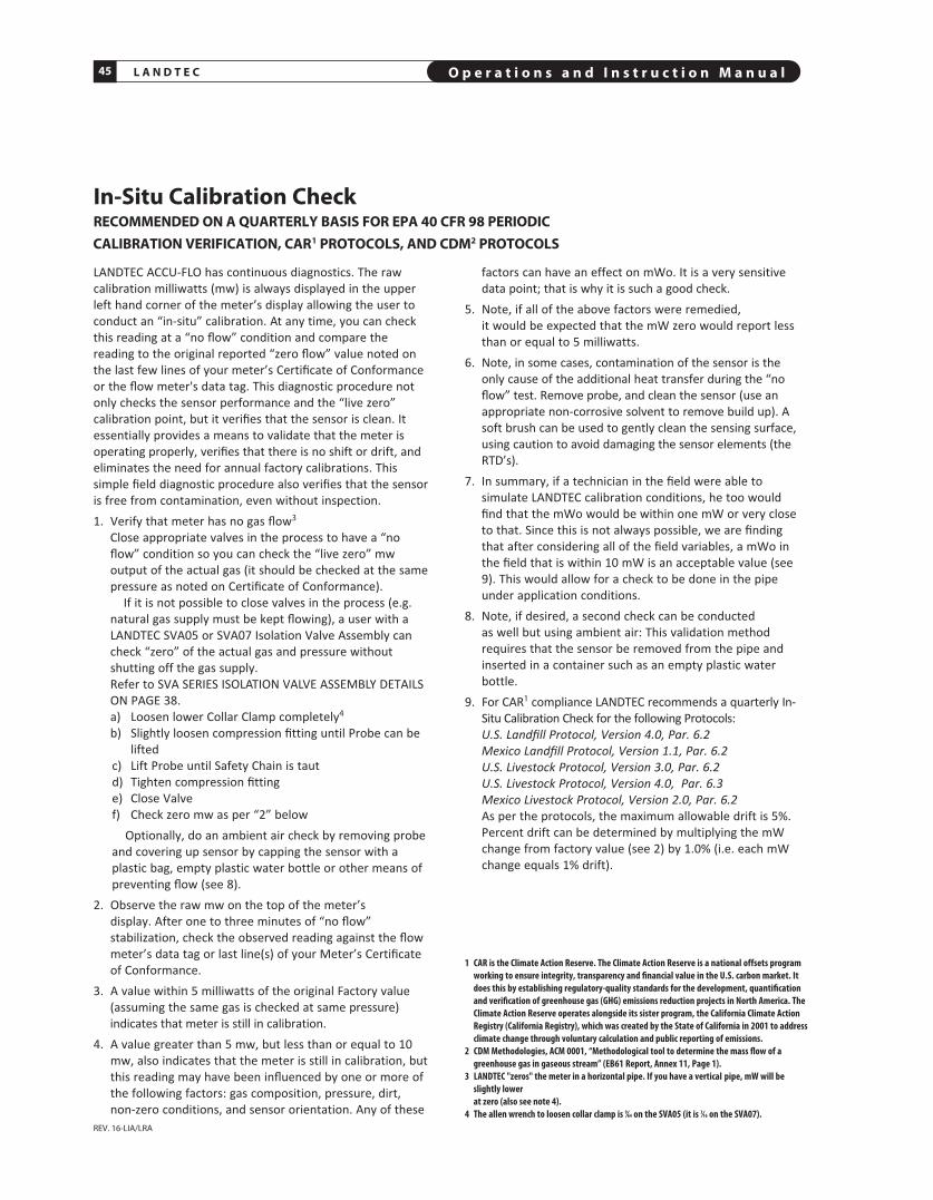
L A N D T E C O p e r a t i o n s a n d I n s t r u c t i o n M a n u a l45
REV. 16-LIA/LRA
In-Situ Calibration CheckRECOMMENDED ON A QUARTERLY BASIS FOR EpA 40 CFR 98 pERIODICCALIBRATION VERIFICATION, CAR1 pROTOCOLS, AND CDM2 pROTOCOLS
LANDTEC ACCU-FLO has continuous diagnostics. The rawcalibration milliwatts (mw) is always displayed in the upperleft hand corner of the meter’s display allowing the user toconduct an “in-situ” calibration. At any time, you can checkthis reading at a “no flow” condition and compare thereading to the original re ported “zero flow” value noted onthe last few lines of your meter’s Certificate of Conformanceor the flow meter's data tag. This diagnostic procedure notonly checks the sensor performance and the “live zero”calibration point, but it verifies that the sensor is clean. Itessentially provides a means to validate that the meter isoperating properly, verifies that there is no shift or drift, andeliminates the need for annual factory calibrations. Thissimple field diagnostic procedure also verifies that the sensoris free from contamination, even without inspection.1. Verify that meter has no gas flow3
Close appropriate valves in the process to have a “noflow” condition so you can check the “live zero” mwoutput of the actual gas (it should be checked at the samepressure as noted on Certificate of Conformance).
If it is not possible to close valves in the process (e.g.natural gas supply must be kept flowing), a user with aLANDTEC SVA05 or SVA07 Isolation Valve Assembly cancheck “zero” of the actual gas and pressure withoutshutting off the gas supply. Refer to SVA SERIES ISOLATION VALVE ASSEMBLY DETAILSON PAGE 38.a) Loosen lower Collar Clamp completely4
b) Slightly loosen compression fitting until Probe can belifted
c) Lift Probe until Safety Chain is taut d) Tighten compression fitting e) Close Valve f) Check zero mw as per “2” below Optionally, do an ambient air check by re moving probe
and covering up sensor by capping the sensor with aplastic bag, empty plastic water bottle or other means ofpreventing flow (see 8).
2. Observe the raw mw on the top of the meter’s display. After one to three minutes of “no flow”stabilization, check the observed reading against the flowmeter’s data tag or last line(s) of your Meter’s Certificateof Conformance.
3. A value within 5 milliwatts of the original Factory value(assuming the same gas is checked at same pressure)indicates that meter is still in calibration.
4. A value greater than 5 mw, but less than or equal to 10mw, also indicates that the meter is still in calibration, butthis reading may have been influenced by one or more ofthe following factors: gas composition, pressure, dirt,non-zero conditions, and sensor orientation. Any of these
factors can have an effect on mWo. It is a very sensitivedata point; that is why it is such a good check.
5. Note, if all of the above factors were remedied, it would be expected that the mW zero would report lessthan or equal to 5 milliwatts.
6. Note, in some cases, contamination of the sensor is theonly cause of the additional heat transfer during the “noflow” test. Remove probe, and clean the sensor (use anappropriate non-corrosive solvent to remove build up). Asoft brush can be used to gently clean the sensing surface,using caution to avoid damaging the sensor elements (theRTD’s).
7. In summary, if a technician in the field were able tosimulate LANDTEC calibration conditions, he too wouldfind that the mWo would be within one mW or very closeto that. Since this is not always possible, we are findingthat after considering all of the field variables, a mWo inthe field that is within 10 mW is an acceptable value (see9). This would allow for a check to be done in the pipeunder application conditions.
8. Note, if desired, a second check can be conducted as well but using ambient air: This validation methodrequires that the sensor be removed from the pipe andinserted in a container such as an empty plastic waterbottle.
9. For CAR1 compliance LANDTEC recommends a quar terly In-Situ Calibration Check for the following Protocols:U.S. Landfill Protocol, Version 4.0, Par. 6.2Mexico Landfill Protocol, Version 1.1, Par. 6.2U.S. Livestock Protocol, Version 3.0, Par. 6.2U.S. Livestock Protocol, Version 4.0, Par. 6.3Mexico Livestock Protocol, Version 2.0, Par. 6.2As per the protocols, the maximum allowable drift is 5%.Percent drift can be determined by multiplying the mWchange from factory value (see 2) by 1.0% (i.e. each mWchange equals 1% drift).
1 CAR is the Climate Action Reserve. the Climate Action Reserve is a national offsets programworking to ensure integrity, transparency and financial value in the U.S. carbon market. Itdoes this by establishing regulatory-quality standards for the development, quantificationand verification of greenhouse gas (GHG) emissions reduction projects in North America. theClimate Action Reserve operates alongside its sister program, the California Climate ActionRegistry (California Registry), which was created by the State of California in 2001 to addressclimate change through voluntary calculation and public reporting of emissions.
2 CDM Methodologies, ACM 0001, “Methodological tool to determine the mass flow of agreenhouse gas in gaseous stream” (EB61 Report, Annex 11, Page 1).
3 LANDtEC "zeros" the meter in a horizontal pipe. If you have a vertical pipe, mW will beslightly lower at zero (also see note 4).
4 the allen wrench to loosen collar clamp is 9⁄64 on the SVA05 (it is 3⁄16 on the SVA07).


Section
WARRANTIES AND SERVICE WORk
E

O p e r a t i o n s a n d I n s t r u c t i o n M a n u a l 49L A N D T E C
REV. 16-LIA/LRA
Warranties and Service Work
LIMITED WARRANTY
LANDTEC products are warranted against faulty materials or
workmanship for one year from the date of shipment from
the factory. LANDTEC’s obligation is limited to repair, or at its
sole option, replacement of products and components
which, upon verification by LANDTEC at our factory in Colton,
California, prove to be defective. LANDTEC shall not be liable
for installation charges, for expenses of Buyer for repairs or
replacement, for damages from delay or loss of use, or other
indirect or consequential damages of any kind. This warranty
is extended only to LANDTEC products properly used and
properly installed for the particular application for which
intended and quoted; and does not cover water damage due
to improper use of cord grips or removal of protective caps;
and does not cover LANDTEC products which have been
altered without LANDTEC authorization or which have been
subjected to unusual physical or electrical stress. LANDTEC
makes no other warranty, express or implied, and assumes
no liability that goods sold to any purchaser are fit for any
particular purpose. Transportation charges for materials
shipped to the factory for warranty repair are to be paid by
the shipper. LANDTEC will return items repaired or replaced
under warranty, prepaid. NOTE: No items will be returned for
warranty repair without prior written authorization from
LANDTEC. LANDTEC does not warranty damage due to
corrosion.
GENERAL TERMS AND CONDITIONS
Detailed General Terms and Conditions can be found on the
LANDTEC website (WWW.LANDTECNA.COM).
CANCELLATION / RETURN pOLICY
Cancellation or Return: After issuance of a purchase order
(by phone, mail, e-mail or fax) or a credit card order (by
phone, mail, e-mail or fax), there will be a cancellation fee
for any cancelled order. Can cella tions must be in writing (by
mail, e-mail or fax):
1) If credit card order or non-credit card order is
cancelled within 7 days of issuance of purchase order or
date order was placed (which ever is
earlier), there will be a 10% cancellation fee.
2) If credit card order or non-credit card order is
cancelled after 7 days, but prior to shipment, there will be
a 20% cancellation fee. (If order is cancelled due to late
delivery, the cancellation
fee will be waived. Late delivery is defined as
shipping a meter 7 days or later than the delivery date
acknowledged by LANDTEC at time of placing order).
3) If a credit card customer decides to return the equipment
after shipment for credit, credit will not be issued if
equipment is damaged or if equipment is returned after
four (4) months of shipment. If equipment is not
damaged, then equipment can be returned after issuance
of a Return Meter Authorization (RMA) by LANDTEC.
Returned package must be insured by customer and
must reference proper RMA# on outside of package, or
package may be rejected (i.e., package will be returned
unopened). Credit Card customers will be charged a 30%
re-stocking fee (70% balance will be credited back).
Customer is responsible for return shipping charges and
any damage if improperly packaged.
continued on next page
L A N D T E C O p e r a t i o n s a n d I n s t r u c t i o n M a n u a l50
4) If a non-credit card customer decides to return
the equipment after shipment for credit, credit will not be
issued if equipment is damaged or if equipment is
returned after 1 month of shipment, unless authorized by
a representative at LANDTEC. The LANDTEC
representative will issue a Return Material Authorization
(RMA) at that time and will advise of the restocking fee.
Returned package must be insured by customer and
must reference proper RMA# on outside of package, or
package may be rejected (i.e., package will be returned
unopened). Customer is responsible for return shipping
charges and any damage if improperly packaged.
REV. 16-LIA/LRA

O p e r a t i o n s a n d I n s t r u c t i o n M a n u a l 51
RETURNING YOUR LANDTEC METER
A Return Material Authorization Number (RMA#) must be
obtained prior to returning any equipment to LANDTEC for
any reason. RMA#s may be obtained by calling LANDTEC at
800-LANDTEC or 909-783-3636 between 8:00 am and 5:00
pm Monday through Friday.
A LANDTEC RMA Form (see page 52) must be filled out and
included with the meter being returned to
LANDTEC.
Take special care when packaging your meter for return to
the factory. The sensor in particular may easily be damaged
if not prevented from shifting around within the package and
if the sensor itself is not covered to keep it from contacting
other package contents. Any damage resulting from
improper packaging is the responsibility of the shipper.
A purchase order is required prior to an RMA being issued.
Most repairs or recalibrations can be quoted over the phone.
For equipment that must be evaluated, an Evaluation
purchase order in the amount of $150 is required. Once an
evaluation is completed and a quote has been issued, you
can choose to proceed with the work or have the unit
returned with only the evaluation and freight fee billed.
In accordance with the “Right to Know Act” and applicable
US Department of Transportation (DOT) regulations,
LANDTEC will not accept delivery of equipment that has been
contaminated without written evidence of decontamination,
and has instituted the following Return/Repair conditions.
Strict adherence to these conditions is required. Returned
equipment that does not conform to the requirements listed
below will not be processed. If LANDTEC finds evidence of
contamination, we may, at our option, have the unit
returned at your expense. For your reference, the
requirements for packaging and labeling hazardous
substances are listed in DOT regulations 49 CFR 172, 178,
and 179.
1. The equipment must be completely cleaned and
decontaminated prior to shipment to LANDTEC. This
decontamination includes the sensor, probe, electronics
and enclosures internally and externally. All packaging
must be clean and free from contamination.
2. A Material Safety Data Sheet (MSDS) is required for all
process fluids and gases that have been in contact with
the equipment. This includes fluids or gases used in
cleaning the equipment. A Decontamination Statement is
also required for each meter returned using a different
gas or fluid. Both the MSDS and the Decontamination
Statement are to be attached to the OUTSIDE of the
shipping container. If both documents are not attached,
you will be called, and the equipment sent back to you at
your expense.
3. The decontamination Statement must include the
following required information
A. A list of all chemicals and process fluids used in the
equipment, including decontamination fluids or gases.
B. The model and serial number of the equipment being
returned.
C. A company officer or other authorized person’s
signature on the statement.
Return Shipping Address:LANDTEC NORTH AMERICA
850 SOUTH VIA LATA, SUITE 112
COLTON, CA 92324
L A N D T E C
REV. 16-LIA/LRA
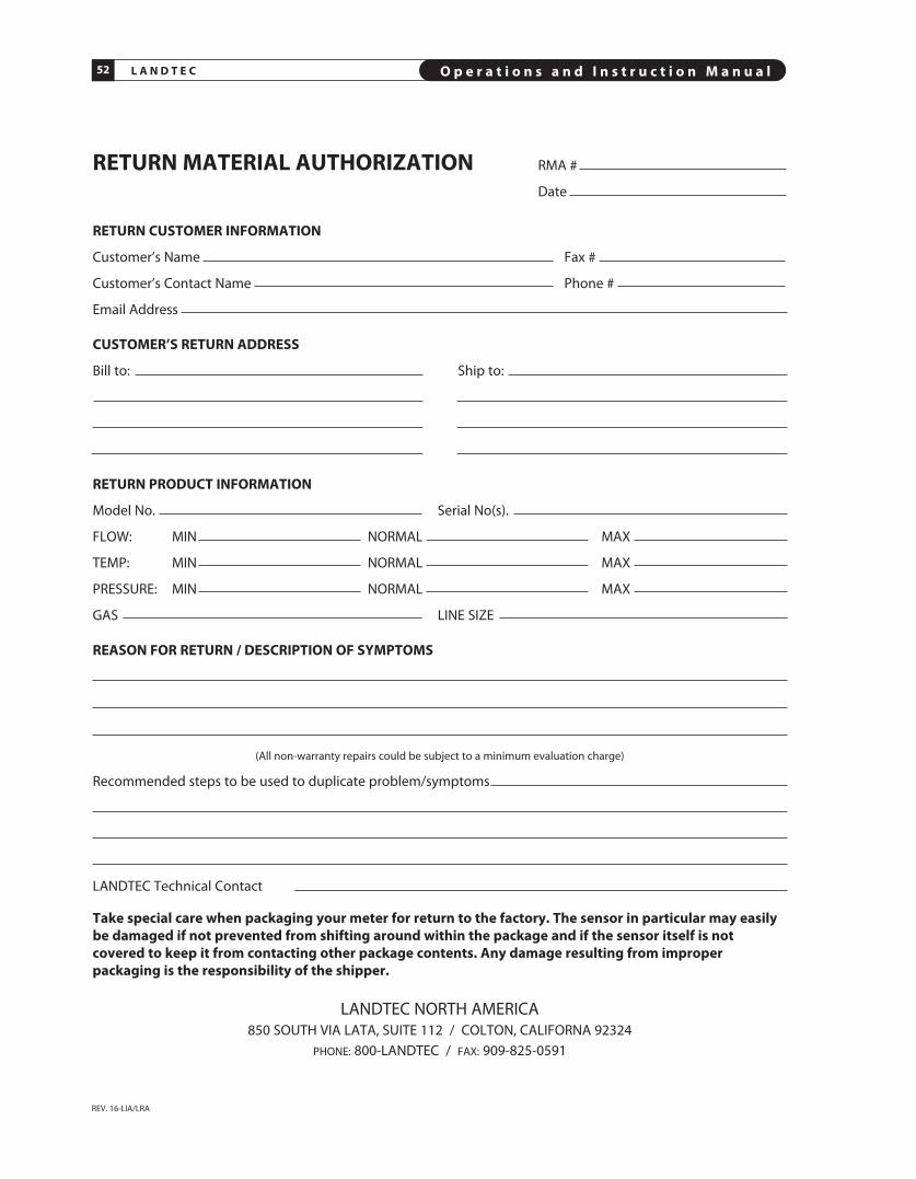
L A N D T E C O p e r a t i o n s a n d I n s t r u c t i o n M a n u a l52
REV. 16-LIA/LRA
RETURN MATERIAL AUTHORIzATION RMA #
Date
RETURN CUSTOMER INFORMATION
Customer’s Name Fax #
Customer’s Contact Name Phone #
Email Address
CUSTOMER’S RETURN ADDRESS
Bill to: ship to:
RETURN pRODUCT INFORMATION
Model No. serial No(s).
FLOW: MIN NORMAL MAX
TEMP: MIN NORMAL MAX
PREssURE: MIN NORMAL MAX
GAs LINE sIZE
REASON FOR RETURN / DESCRIpTION OF SYMpTOMS
(All non-warranty repairs could be subject to a minimum evaluation charge)
Recommended steps to be used to duplicate problem/symptoms
LANDTEC Technical Contact
Take special care when packaging your meter for return to the factory. The sensor in particular may easilybe damaged if not prevented from shifting around within the package and if the sensor itself is notcovered to keep it from contacting other package contents. Any damage resulting from improperpackaging is the responsibility of the shipper.
LANDTEC NORTH AMERICA850 sOUTH VIA LATA, sUITE 112 / COLTON, CALIFORNA 92324
PHONE: 800-LANDTEC / FAX: 909-825-0591

Section
MODBUS
F


O p e r a t i o n s a n d I n s t r u c t i o n M a n u a l 55L A N D T E C
REV. 16-LIA/LRA
Modbus Register ListingLANDTEC ACCU-FLO REV. 1.80–2.07
*SCALED INT32 register contents form INT32 values by multiplying the IEEE FLOAT x 1000ex. FLOAT –> 112.768 = SCALED INT32 –> 112768
256
256
257
257
257
257
257
257
257
257
257
tEMP
tEMP
tEMP
tEMP
fLOW
fLOW
fLOW
fLOW
fLOW
fLOW
514
516
518
520
522
524
526
528
530
532
534
536
538
540
542
544
546
548
770
772
774
776
778
780
782
784
786
788
790
792
794
796
798
800
802
804
UINt8
UINt8
UINt8
UINt8
UINt1
UINt1
UINt1
UINt1
UINt1
UINt1
UINt1
fLOAt
fLOAt
fLOAt
fLOAt
fLOAt
fLOAt
fLOAt
fLOAt
fLOAt
fLOAt
fLOAt
fLOAt
fLOAt
fLOAt
fLOAt
fLOAt
fLOAt
fLOAt
LONG
LONG
LONG
LONG
LONG
LONG
LONG
LONG
LONG
LONG
LONG
LONG
LONG
LONG
LONG
LONG
LONG
LONG
UINt32 IEEE float SCALED INt32*
Reg Reg Reg Reg Offset Offset type Offset type Description
format flag
modbus_unit_id
output mode sel
fix_pt selection
bRun
btotal
bEEProm
bReset
bLeadEn
bDACIo
bDAChi
CAL_VAL
K-fACtOR
VREf
LOAD-RES
COEff A
COEff B
COEff C
COEff D
DISP A
DISP B
DISP C
DISP D
COEff A
COEff B
COEff C
COEff D
COEff E
COEff f
302
304
306
308
310
312
314
316
318
320
550
552
554
556
558
578
580
582
584
586
588
590
592
594
596
598
600
602
806
808
810
812
814
834
836
838
840
842
844
846
848
850
852
854
856
858
fLOAt
fLOAt
fLOAt
fLOAt
fLOAt
UINt16
UINt16
UINt32
ASCII
ASCII
UINt32
UINt32
UINt32
UINt32
UINt32
fLOAt
fLOAt
fLOAt
fLOAt
fLOAt
fLOAt
fLOAt
fLOAt
fLOAt
fLOAt
fLOAt
fLOAt
fLOAt
LONG
LONG
LONG
LONG
LONG
LONG
LONG
LONG
LONG
LONG
LONG
LONG
LONG
UINt32 IEEE float SCALED INt32*
Reg Reg Reg Reg Offset Offset type Offset type Description
iir filter coeff
flow_min
flow_max
PULSE COUNt
temp_max
dac1_min
dac1_max
serial number
RAtE string
tOtAL string
current totalizer
ADC0
ADC1
ADC2
ADC3
current flow
current temp
rtd_mWatts
rtd_res
ref_res_r
ref_res_d
dac_smooth
lead
oheat
bv
fv
tv
lv

L A N D T E C O p e r a t i o n s a n d I n s t r u c t i o n M a n u a l56
REV. 16-LIA/LRA
LANDTEC ACCU-FLO Meters support communication with
other devices via MODBUS® protocol using RTU transmission
mode. The Modbus protocol defines a message structure
that controllers will recognize and use, regardless of the type
of networks over which they communicate. It establishes a
common format for the layout and contents of message
fields. Transactions use a master-slave technique, in which
only one device (the master) can initiate transactions (called
queries). The other devices (the slaves) respond by supplying
the requested data to the
master and by taking the action requested in the query.
LANDTEC Meters operate as slaves to other Modbus devices
and default to 19200-8-E-1, however, the
following modes may also be software selectable:
9600-8-N-1 (Baud-Bits-Parity-stop) 9600-8-E-1 9600-8-O-1 19200-8-N-11
19200-8-E-1 (Default) 19200-8-O-1
MESSAGE FRAMINGMessages start with a silent interval of at least 3.5 character
times followed by 4 fields and then followed by another
silent interval of at least 3.5 character times. The first field
contains the device address. The second field contains the
function code. The third field contains the data and byte
counts. The fourth field contains the CRC value.
ADDRESS FIELDThe address field contains one byte. LANDTEC ACCU-FLO
Meters will transmit response packets to addresses which
are between 1 to 240 decimal (inclusive). Modbus packet
writes may be sent to broadcast address 00, however the
ACCU-FLO will not reply with a response packet.
FUNCTION CODE FIELDThe function code field contains one byte. See the section
titled Function Codes Supported by LANDTEC ACCU-FLO.
DATA FIELDThe data field contains four or more bytes. This information
is used by the Meter to take the action defined by the
function code, or to read or write data to one or many
registers.
CRC FIELDThe CRC-16 (cyclical redundancy check) field is two bytes,
containing a 16-bit binary value. The CRC value is calculated
by the transmitting device, which appends the CRC to the
message. The receiving device recalculates a CRC during
receipt of the message, and compares the calculated value to
the actual value it received in the CRC field. If the two values
are not equal, the message will be discarded.
LANDTEC Modbus protocol Rev. 1.80–Rev. 2.07
1 Parity on the wireless Devices manufactured by Obvius is “None” rather than “Even”. The LANDTECdefault is 19200-8-E-1. Change to 19200-8-N-1 for the Obvius Modhoppers and related wirelessdevices.
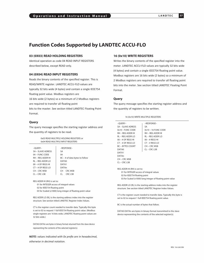
O p e r a t i o n s a n d I n s t r u c t i o n M a n u a l 57L A N D T E C
REV. 16-LIA/LRA
03 (0X03) READ HOLDING REGISTERSIdentical operation as code 04 READ INPUT REGISTERS
described below, except READ only.
04 (0X04) READ INpUT REGISTERSReads the binary contents of the specified register. This is
READ/WRITE register. LANDTEC ACCU-FLO values are
typically 32 bits wide (4 bytes) and contain a single IEEE754
floating point value. Modbus registers are
16 bits wide (2 bytes) so a minimum of 2 Modbus registers
are required to transfer all floating point
bits to the master. See section titled LANDTEC Floating Point
Format.
QueryThe query message specifies the starting register address and
the quantity of registers to be read.
0x03 READ MULTIPLE HOLDING REGIsTERs or 0x04 READ MULTIPLE INPUT REGIsTERs
–QUERY– –REsPONsE– sA – sLAVE ADREss sA 04 – FUNC CODE 04 RH – REG ADDR HI BC – # of data bytes to follow RL – REG ADDR LO DATA0 00 – # OF REGs HI DATA1 CT – # OF REGs LO DATAn CH – CRC MsB CH CRC MsB CL – CRC LsB CL CRC LsB
REG ADDR HI (RH) is set to: 01 for INTEGER access of integral values 02 for IEEE754 floating point 03 for scaled (x1000) long integer of floating point value
REG ADDR LO (RL) is the starting address index into the registerstructure. see section titled LANDTEC Register Index Values.
CT is the register count needed to transfer data. Typically this byte is set to 02 to request 1 full IEEE754 floating point value. (Modbussingle registers are 16 bits wide, LANDTEC floating point values are 32 bits wide.)
DATA0-DATAn are bytes in binary format returned from the slave device
representing the contents of the selected register(s).
NOTE: values indicated with 0x prefix are in hexadecimal,
otherwise in decimal notation.
Function Codes Supported by LANDTEC ACCU-FLO
16 (0x10) WRITE REGISTERSWrites the binary contents of the specified register into the
meter. LANDTEC ACCU-FLO values are typically 32 bits wide
(4 bytes) and contain a single IEEE754 floating point value.
Modbus registers are 16 bits wide (2 bytes) so a minimum of
2 Modbus registers are required to transfer all floating point
bits into the meter. See section titled LANDTEC Floating Point
Format.
QueryThe query message specifies the starting register address and
the quantity of registers to be written.
16 (0x10) WRITE MULTIPLE REGIsTERs
–QUERY– –REsPONsE– sA – sLAVE ADREss sA
0x10 – FUNC CODE 0x10 – 16 FUNC CODERH – REG ADDR HI RH – REG ADDR HIRL – REG ADDR LO RL – REG ADDR LO00 – # OF REGs HI 00 – # REGs HICT – # OF REGs LO CT – # REGs LOBC – BYTEs COUNT CH – CRC MsBDATA0 CL – CRC LsBDATA1 DATAn CH – CRC MsB CL – CRC LsB
REG ADDR HI (RH) is set to: 01 for INTEGER access of integral values 02 for IEEE754 floating point 03 for scaled (x1000) long integer of floating point value
REG ADDR LO (RL) is the starting address index into the registerstructure. see section titled LANDTEC Register Index Values.
CT is the register count needed to transfer data. Typically this byte isset to 02 to request 1 full IEEE754 floating point value.
BC is the actual number of bytes that follow.
DATA0-DATAn are bytes in binary format transmitted to the slavedevice representing the contents of the selected register(s).

O p e r a t i o n s a n d I n s t r u c t i o n M a n u a l 58L A N D T E C
17 (0x11) REpORT SLAVE IDENTIFICATION*This query requests from the specified slave address
a detailed identification packet with a run status, and
LANDTEC ACCU-FLO and firmware revision response. (ACCU-
FLO will not respond to broadcast slave address 00.)
QueryThe query message specifies the slave address, function
code, and CRC check words.
17 (0x11) REPORT sLAVE ID
–QUERY– –REsPONsE– sA – sLAVE ADREss sA 11 – FUNC CODE 11 CL – CRC LsB BC – BYTEs COUNT, 19 CH – CRC MsB sD – sLAVE ID (DEVICE sPECIFIC), 0x5A Rs – RUN sTATUs INDICATOR, 0xFF AsCII Text – LANDTEC ACCU-FLO v1.81x CH CL
ResponseThe LANDTEC ACCU-FLO will respond with an echo of the slaveaddress and function code. The byte count will be 19 (0x13) to allowthe master to account for all the remaining bytes that follow.
REPORT sLAVE ID Example: (slave Address = 0x30 = 48, default)Master Query –> 30 11 D5 BCACCU-FLO Response –> 30 11 13 5A FF 53 61 6765 20 50 72 69 6D 65 20 76 31 2E 38 31 20 F1 2BAsCII translation–> LANDTEC ACCU-FLO v1.81
NOTE: THIS pAGE AppLIES TO REV. 1.81–1.83
ILLEGAL FUNCTION CODES*The LANDTEC ACCU-FLO will respond to other Modbus
function codes not documented in this revision, these codes
are considered unsupported by LANDTEC. Unsupported
function codes will cause the ACCU-FLO to reply with
Modbus ILLEGAL FUNCTION status.
*Not implemented in revision 1.80
LANDTEC REGISTER INDEX VALUES
DATA ADDREssTYPE VALUE sIZE INDEX DEsCRIPTIONByte slave_ad 1 BYTE 1 Modbus slave Address*float flow_rate; 1 IEEE754 578 actual flow ratefloat flow_temp; 1 IEEE754 580 process temperaturefloat rtd_mWatts; 1 IEEE754 582 sensor power readingfloat rtd_res; 1 IEEE754 584 actual sensor probe resistancefloat ref_res_r; 1 IEEE754 586 actual temperature probe resistanceinteg totalizer; 1 uLONG 312 actual displayed total
*NOTE: LANDTEC ACCU-FLO Meters are factory programmed with the MODBUS slave address = 48 (0x30). It may be extremely useful to be able to write to an unknown slave address with a simple broadcastcommand. Be sure only one LANDTEC ACCU-FLO is connected during any broadcast writes using slave address = 0.
Writing into unspecified registers (not defined above) can
render the unit non-functional or overwrite factory
calibration data yielding incorrect operation.
EXAMpLE MODBUS pACkET
QueryThis packet will request of the addressed slave to respond by
sending back the contents of registers 578 to 582 (inclusive).
Three registers: flow rate through RTD mWatts in IEEE754
floating point
format.
0x31 – LANDTEC ACCU-FLO sLAVE ADDREss (0x31 Hex = 49 Decimaldefault)0x04 – READ INPUT REGs FUNCTION CODE0x02 – sTARTING REGIsTER HI BYTE (0x01 = 256, 0x02 = 512, 0x03 = 768)0x42 – sTARTING REGIsTER LO BYTE (512 + 66 = register access = 578)0x00 – COUNT MsB (ALWAYs ZERO)0x06 – COUNT OF ALL DEsIRED REGIsTERs0xD5 – CRC HI BYTE0x85 – CRC LO BYTE
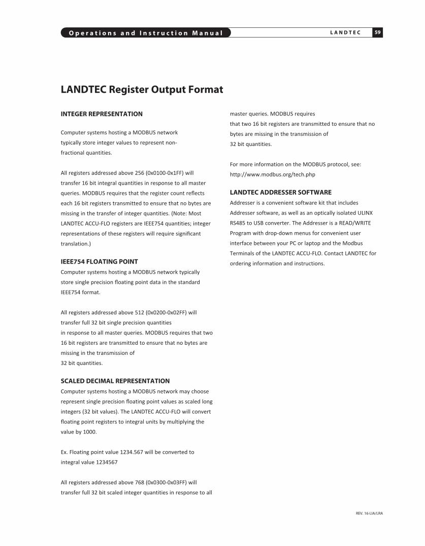
O p e r a t i o n s a n d I n s t r u c t i o n M a n u a l 59L A N D T E C
REV. 16-LIA/LRA
INTEGER REpRESENTATION
Computer systems hosting a MODBUS network
typically store integer values to represent non-
fractional quantities.
All registers addressed above 256 (0x0100-0x1FF) will
transfer 16 bit integral quantities in response to all master
queries. MODBUS requires that the register count reflects
each 16 bit registers transmitted to ensure that no bytes are
missing in the transfer of integer quantities. (Note: Most
LANDTEC ACCU-FLO registers are IEEE754 quantities; integer
representations of these registers will require significant
translation.)
IEEE754 FLOATING pOINTComputer systems hosting a MODBUS network typically
store single precision floating point data in the standard
IEEE754 format.
All registers addressed above 512 (0x0200-0x02FF) will
transfer full 32 bit single precision quantities
in response to all master queries. MODBUS requires that two
16 bit registers are transmitted to ensure that no bytes are
missing in the transmission of
32 bit quantities.
SCALED DECIMAL REpRESENTATIONComputer systems hosting a MODBUS network may choose
represent single precision floating point values as scaled long
integers (32 bit values). The LANDTEC ACCU-FLO will convert
floating point registers to integral units by multiplying the
value by 1000.
Ex. Floating point value 1234.567 will be converted to
integral value 1234567
All registers addressed above 768 (0x0300-0x03FF) will
transfer full 32 bit scaled integer quantities in response to all
LANDTEC Register Output Format
master queries. MODBUS requires
that two 16 bit registers are transmitted to ensure that no
bytes are missing in the transmission of
32 bit quantities.
For more information on the MODBUS protocol, see:
http://www.modbus.org/tech.php
LANDTEC ADDRESSER SOFTWAREAddresser is a convenient software kit that includes
Addresser software, as well as an optically isolated ULINX
RS485 to USB converter. The Addresser is a READ/WRITE
Program with drop-down menus for convenient user
interface between your PC or laptop and the Modbus
Terminals of the LANDTEC ACCU-FLO. Con tact LANDTEC for
ordering information and instructions.

L A N D T E C O p e r a t i o n s a n d I n s t r u c t i o n M a n u a l60
REV. 16-LIA/LRA
LANDTEC Addresser Typical printout (Version 3.14)
Units: SCFM Modbus:0x31
Copyright 2014, LANDTEC NORTH AMERICA, INC. 1 of 1


GSection
AppENDIX
G

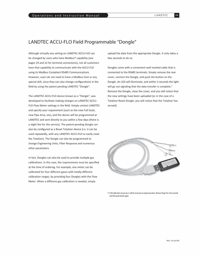
O p e r a t i o n s a n d I n s t r u c t i o n M a n u a l 64L A N D T E C
REV. 16-LIA/LRA
LANDTEC ACCU-FLO Field Programmable “Dongle”
Although virtually any setting on LANDTEC ACCU-FLO can
be changed by users who have Modbus® capability (see
pages 19 and 22 for terminal connections), not all customers
have that capability to communicate with the ACCU-FLO
using its Modbus Compliant RS485 Communications.
However, users do not need to have a Modbus host or any
special skill, since they can also change configurations in the
field by using the patent pending LANDTEC “Dongle”.
The LANDTEC ACCU-FLO device known as a “Dongle”, was
developed to facilitate making changes on LANDTEC ACCU-
FLO Flow Meter settings in the field. Simply contact LANDTEC
and specify your requirement (such as the new Full Scale,
new Pipe Area, etc), and the device will be programmed at
LANDTEC and sent directly to you within a few days (there is
a slight fee for this service). The patent-pending Dongle can
also be configured as a Reset Totalizer device (i.e. it can be
used repeatedly, with any LANDTEC ACCU-FLO to easily reset
the Totalizer). The Dongle can also be programmed to
change Engineering Units, Filter Response and numerous
other parameters.
In fact, Dongles can also be used to provide multiple gas
calibrations. In this case, the requirements must be specified
at the time of ordering. For example, one meter can be
calibrated for four different gases with totally different
calibration ranges, by providing four Dongles with the Flow
Meter. When a different gas calibration is needed, simply
upload the data from the appropriate Dongle. It only takes a
few seconds to do so.
Dongles come with a convenient well marked cable that is
connected to the RS485 terminals. Simply remove the rear
cover, connect the Dongle, and push the button on the
Dongle. An LED will illuminate, and within 3 seconds the light
will go out signaling that the data transfer is complete.1
Remove the Dongle, close the cover, and you will notice that
the new settings have been uploaded (or in the case of a
Totalizer-Reset Dongle, you will notice that the Totalizer has
zeroed).
1 If the light does not go out, it will be necessary to repeat procedure. Remove finger for a few secondsand then push button again.
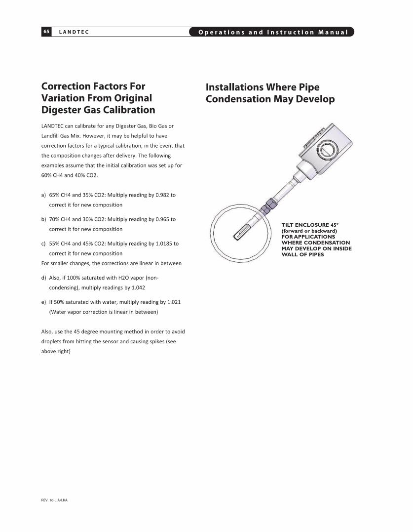
L A N D T E C O p e r a t i o n s a n d I n s t r u c t i o n M a n u a l65
REV. 16-LIA/LRA
TILT ENCLOSURE 45º (forward or backward) FOR APPLICATIONSWHERE CONDENSATIONMAY DEVELOP ON INSIDEWALL OF PIPES
Correction Factors ForVariation From OriginalDigester Gas CalibrationLANDTEC can calibrate for any Digester Gas, Bio Gas or
Landfill Gas Mix. However, it may be helpful to have
correction factors for a typical calibration, in the event that
the composition changes after delivery. The following
examples assume that the initial calibration was set up for
60% CH4 and 40% CO2.
a) 65% CH4 and 35% CO2: Multiply reading by 0.982 to
correct it for new composition
b) 70% CH4 and 30% CO2: Multiply reading by 0.965 to
correct it for new composition
c) 55% CH4 and 45% CO2: Multiply reading by 1.0185 to
correct it for new composition
For smaller changes, the corrections are linear in between
d) Also, if 100% saturated with H2O vapor (non-
condensing), multiply readings by 1.042
e) If 50% saturated with water, multiply reading by 1.021
(Water vapor correction is linear in between)
Also, use the 45 degree mounting method in order to avoid
droplets from hitting the sensor and causing spikes (see
above right)
Installations Where pipeCondensation May Develop

O p e r a t i o n s a n d I n s t r u c t i o n M a n u a l 66L A N D T E C
REV. 16-LIA/LRA
J-Box and Upstream Orientation
5.0
4.40
5.0
2.72 2.72
FLOW DIRECTION
FLOW DIRECTION
FRONT VIEW LOOKING DOWNSTREAM LOOKING UPSTREAM
FLOW DIRECTION
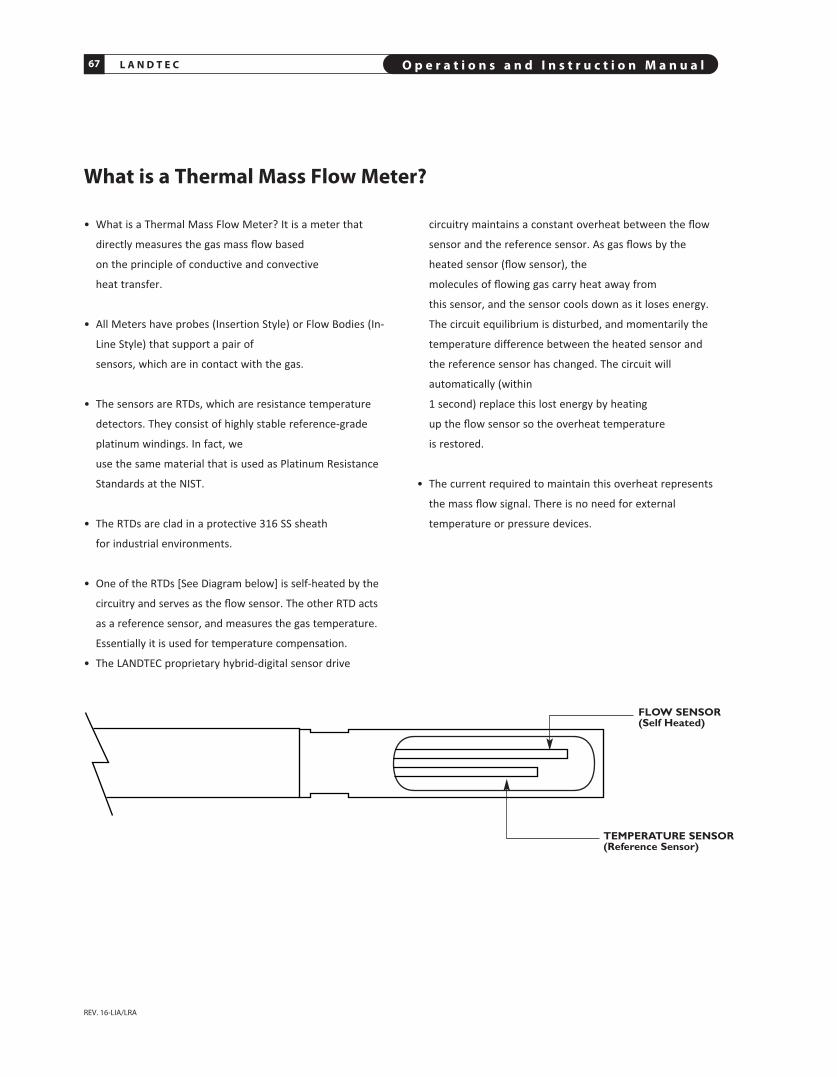
L A N D T E C O p e r a t i o n s a n d I n s t r u c t i o n M a n u a l67
REV. 16-LIA/LRA
What is a Thermal Mass Flow Meter?
FLOW SENSOR(Self Heated)
TEMPERATURE SENSOR(Reference Sensor)
• What is a Thermal Mass Flow Meter? It is a meter that
directly measures the gas mass flow based
on the principle of conductive and convective
heat transfer.
• All Meters have probes (Insertion Style) or Flow Bodies (In-
Line Style) that support a pair of
sensors, which are in contact with the gas.
• The sensors are RTDs, which are resistance tem perature
detectors. They consist of highly stable reference-grade
platinum windings. In fact, we
use the same material that is used as Platinum Resistance
Standards at the NIST.
• The RTDs are clad in a protective 316 SS sheath
for industrial environments.
• One of the RTDs [See Diagram below] is self-heated by the
circuitry and serves as the flow sensor. The other RTD acts
as a reference sensor, and measures the gas temperature.
Essen tial ly it is used for temperature compensation.
• The LANDTEC proprietary hybrid-digital sensor drive
circuitry maintains a constant overheat between the flow
sensor and the reference sensor. As gas flows by the
heated sensor (flow sensor), the
molecules of flowing gas carry heat away from
this sensor, and the sensor cools down as it loses energy.
The circuit equilibrium is disturbed, and momentarily the
temperature difference between the heated sensor and
the reference sensor has changed. The circuit will
automatically (within
1 second) replace this lost energy by heating
up the flow sensor so the overheat temperature
is restored.
• The current required to maintain this overheat represents
the mass flow signal. There is no need for external
temperature or pressure devices.