languages and tools for rule modeling - citeseerx
TRANSCRIPT

Languages for Rule Modeling
Running head: LANGUAGES AND TOOLS FOR RULE MODELING
Languages and Tools for Rule Modeling
Grzegorz J. Nalepa
AGH University of Science and Technology
1

ABSTRACT
This chapter presents selected practical issues of rule modeling. This field combines both classic Artificial Intelligence methods and Software Engineering. The chapter gives a concise presentation of selected relevant methods, and approaches, put in an engineering perspective. The modeling language used in the communication between business analysts and experts for analyzing the system requirements should not be too technical. It should allow for visual rule expressions, which can be understood by experts without an extensive technical training. The main goals of this chapter are: to summarize the formal foundations of rules, found in the field of AI, including decision tables and trees; discuss main challenges in practical rule design, and modeling; introduce selected recent research in the field of rule design, focusing on visual modeling; as well as observe some important future trends in rule design and integration. In the chapter it is argued that efficient visual rule modeling methods are crucial for developing complex rule systems.

Languages and Tools for Rule Modeling
INTRODUCTION AND MOTIVATION
Designing rule-based systems is not a trivial task. Standard software design approaches cannot be used directly, due some fundamental differences between knowledge and software engineering. These include non-procedural declarative knowledge specification, as well as important semantic differences between the rule-based representation and conventional design and programming languages.
The motivation of this chapter is to present selected practical issues of rule modeling. This field combines both classic Artificial Intelligence (AI) (Russell & Norvig, 2003) methods and Software Engineering (SE) (Sommerville, 2004). In AI rules have been studied as a classic knowledge representation method (Brachman & Levesque, 2004, Ligęza, 2006, Harmelen & Lifschitz & Porter, 2007) for expert systems (Liebowitz, 1998, Giarratano & Riley, 2005). Some recent developments in Software Engineering, mainly in business rules systems make it use the AI experiences, putting them in a new context. The chapter gives a concise presentation of selected relevant methods, and approaches, put in an engineering perspective.
Principal objectives of this chapter are:
• to summarize the formal foundations of rules, found in the field of AI, including decision tables and trees,
• discuss main challenges in practical rule design, and modeling,
• introduce selected recent research in the field of rule design, focusing on visual modeling,
• observe some important future trends in rule design and integration.
In this chapter it is argued that efficient visual rule modeling methods are crucial for developing complex rule systems.
BACKGROUND
Knowledge Representation
Rules are both prime and classic example of a knowledge representation method (Brachman & Levesque, 2004, Harmelen & Lifschitz & Porter, 2007). Such methods are developed within knowledge engineering. It is a field of Artificial Intelligence applied to building intelligent systems, systems that represent and process knowledge.
Knowledge is often defined as justified true belief (Torsun, 1995). So it is then a set of facts or true statements about a world. A representation in a broad sense may be defined as “the symbolic representation of justified true beliefs or a model of some universe of discourse”(Torsun, 1995).
It is widely recognized that there is no single formalism suitable to represent knowledge for all purposes. A variety of formalisms and structures is needed. In the field of expert systems (Liebowitz, 1998, Giarratano & Riley, 2005) the knowledge representation method is a systematic

way of “encoding” what an expert knows about some domain (Jackson, 1999). However "encoding'' means here rather “describing” than “encrypting”.
Some of the issues arising in a knowledge representation are: syntax, semantics, expressive adequacy, reasoning, completeness, real-world relevance, flexibility. Different representations address these issues in different ways. While there are numerous knowledge representation methods, the logic-based ones are essential to the theory and practice of expert systems and rule systems in general.
In the chapter some fundamental logical rule formats are considered. They are a basis for rule languages. Rules can be practically written and processed in the logic programming paradigm, e.g. in Prolog (Bratko, 2000). Even though the language uses a subset of first order predicate logic (restricted to Horn clauses), it is easy to write meta-interpreters working another languages.
Decision Rules
Decision rules are one of the most important and successful knowledge representation methods. Systems based on rules, the so called rule-based expert systems, or just rule-based systems (RBS) find numerous applications in many fields, from decision support in areas ranging from business to medicine, to intelligent control. This is due to the fact that rules have an intuitive, straightforward semantics, close to the natural language, making them accessible to non-experts. Simultaneously, they also have a clear formal description, which allows for both formalized design and analysis of mission-critical rule-based systems.
A general rule expression corresponds to a conditional statement in the natural language. Often this statement is simply presented as:
IF some condition is met THEN some conclusion may be driven
While this may seem simple and straightforward, it is in fact imprecise. The actual semantics depends on the expressive power of the conditional language, as well as the conclusion description.
In RBS, a rule has a general format:
IF condition THEN decision
This format can be used in both forward and backward chaining systems. However, here we focus on the production rule systems, based on the forward chaining paradigm. The power of a rule language stems from the syntax and semantics of the conditional and decision expressions. Number of systems implicitly assume, that this rule format can be extended to the conjunctive normal form (CNF), that is:
IF cond1 AND cond2 AND ... AND condN
THEN decision
which in fact corresponds to a Horn clause F (Ben-Ari, 2001, Ligęza, 2006), that is:
F = ~p1 v ~p2 v ... ~pk v q
Such a clause can be represented as an implication of the form:
p1 ^ p2 ^ ... ^ pk -> q

which can be regarded as a rule in the above format, where ps correspond to conditions and q corresponds to the decision. In fact the Prolog language uses a subset of predicate calculus, restricted to Horn clauses (Covington & Nute & Vellino, 1996, Bratko, 2000).
The question is what are the conditional and decision expressions. In a number of systems these correspond to expressions in the propositional calculus, which makes the semantics somehow limited. Some systems try to use some subsets of predicate logic, which gives much more flexibility, but may complicate the RBS design and the inference process. This is the case of Prolog. In XTT (eXtended Tabular Trees) (Nalepa & Ligęza, 2005b) these expressions are in the the attributive logic (Ligęza, 2006). This gives much more power than the propositional logic, but does not introduce problems of the predicate logic-based inference.
Two important factors have to be taken into the consideration: what is the formal calculus used in rules, and how rule are interpreted. Considering the first aspect the propositional and predicate calculi have to be considered (Ben-Ari, 2001). Using quantifiers, it is possible to specify constraint, or integration rules. The second aspect involves forward chaining and backward chaining. Considering these contexts the production and derivation rules are identified.
Consider a set of production rules (a similar example may be found at openrules.com):
IF age =< 12 THEN greeting = littleIF age > 12 AND sex = male THEN greeting = Mr.IF age > 12 AND sex = female AND martial = single THEN greeting = Ms.IF age > 12 AND sex = female AND martial = married THEN greeting = Mrs.
It is a common engineering practice to support the system design with a visual representation. This is also a case with rule-based systems. Giving a proper formulation of rules, it is possible to provide a visual rule representation which is logically equivalent to certain rule sets. Visual forms of rule-based systems incorporate elements of a structure into a rule set. This structure provides an intuitive visualization of the system, often oriented towards a specific application, and it also imposes a specific interpretation rules, especially with respect to the order of rules and preconditions. Two most important representations are discussed, these are: decision tables, and decision trees.
Decision Tables
A decision table represents a set of similar rules grouped with respect to used preconditions and conclusions or actions. The rules covered by a decision table form a kind of a decision unit designed to work in a given context. A classical decision table is a table displaying sequences of conditions which must hold for executing specific actions or drawing specific conclusions. The sequences of conditions are displayed in a readable form, vertically in the classical decision tables, as parts of columns of the decision table, or horizontally, as parts of rows of the table (Brachman & Levesque, 2004, Ligęza, 2006). A decision table corresponding to the set of rules presented in the previous section is shown in Fig. 1.
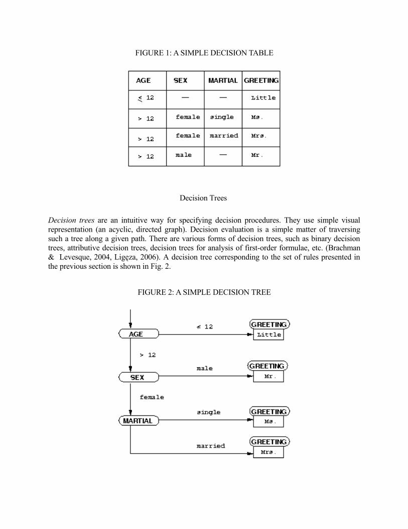
FIGURE 1: A SIMPLE DECISION TABLE
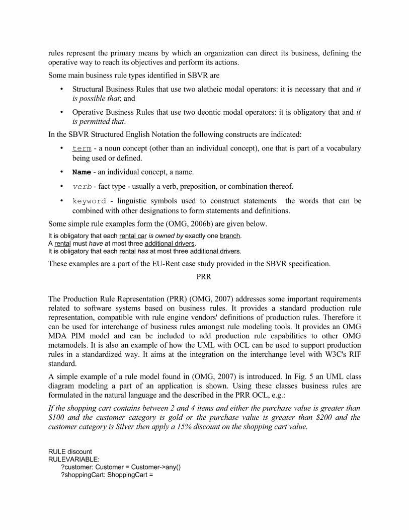
Decision Trees
Decision trees are an intuitive way for specifying decision procedures. They use simple visual representation (an acyclic, directed graph). Decision evaluation is a simple matter of traversing such a tree along a given path. There are various forms of decision trees, such as binary decision trees, attributive decision trees, decision trees for analysis of first-order formulae, etc. (Brachman & Levesque, 2004, Ligęza, 2006). A decision tree corresponding to the set of rules presented in the previous section is shown in Fig. 2.
FIGURE 2: A SIMPLE DECISION TREE

Binary Decision Trees (BDT) are perhaps the best known and most popular decision structures used in a number of domains. For intuition, binary decision tree is a structure leading through a series of simple tests to arrive at a certain decision. The tests are limited to evaluation of a propositional statement, which can be true or false, and hence the trees are referred to as binary.
Business Rules Design
Business rules (BR) approach (Ross, 2003, Halle, 2001) is a new approach to rule design for business applications based on concepts borrowed from knowledge engineering (KE) and rule-based systems. It is becoming an important approach in business application development, especially on the Java platform. A classic description of the main principles of the approach is given in (Ross, 2003). According to it, rules should be: written and made explicit, expressed in plain language, motivated by identifiable and important business factors, single sourced, specified directly by people who have relevant knowledge, managed, and built on facts, and facts should build on concepts. Rules should also exist independent of procedures and workflows.
There are number of rule types identified in the BR approach, such as: reactive rules (event-condition-action rules), transformation rules (functional-equational rules), derivation rules (implicational-inference rules), also ones restricted to facts (“premiseless” derivation rules) and queries (“conclusionless” derivation rules), as well as integrity-constraints (consistency-maintenance rules).
From the point of view of formal knowledge engineering, a major issue with current BR methods is related to the logical foundations of BR systems. From a point of view of classical KE, a rule-based expert system consists of a knowledge base and an inference engine. The KE process aims at designing and evaluating the knowledge base, and implementing a proper inference engine. The process of building the knowledge base involves the selection of a knowledge representation method, knowledge acquisition, and possibly low-level knowledge encoding. In order to create an inference engine a reasoning technique must be selected, and the engine has to be programmed.
Unfortunately it can be observed, that common approaches to BR tend to mix these formal aspects. While there are attempts to officially define main aspects of the approach, e.g. the Semantics of Business Vocabulary and Business Rules Specification, see (OMG, 2006b), these formulation attempts are definitely not satisfactory. The main source of problems seems to be the way in which the rich semantics of business rules is being captured. The problem of defining the business rules vocabulary, seems to fall into the domain of natural language processing. The other problem is the lack of explicit choice of logical calculus. This poses severe problems when it comes to formal description of BR syntax, semantics, and inference.
Persistent Problems of Rule Modeling
Even though the issue of rule modeling has been present in the AI and engineering research for years, some important practical problems in this area persist. They are especially exposed in the case of business rules modeling. They are partially due to growing complexity of the rule systems, as well as the need for a tighter integration with existing business applications designed with the software engineering methods.

The first problem is related to apparent shortcomings or even lack of a coherent formal description of rule systems being modeled. This poses problems with both formal analysis and formally defined translation of rules.
The second problem is related to the visual representation used in the design of rule systems. Visual representations used, have scalability problems (it's easy to draw diagrams of several rules, but it becomes very difficult to cope with tens of rules). Lack of well-defined formal foundations of these representations leads to problems with automatic transformation of visual model to the logical one. When introducing a visual representation, it is important to decide what is the main reason for its introduction. Is it just some useful conceptualization tool, helpful in the design; or is it an integral part of the design process.
The third problem concerns the formal analysis and verification of rule systems. As the number of rules exceeds even relatively very low quantities, it is hard to keep the rule-base consistent, complete, and correct. These problems are related to knowledge-base verification, and validation The selection of appropriate software tools and programming languages is non-trivial either.
These issues are often neglected in rule modeling. It seems that analysis (where issues such as verification, validation, and evaluation are even not properly separated) is simply considered testing. So the analysis of the knowledge base is implicitly substituted by testing of the implementation. However, in the KE approach, a proper formal analysis of the knowledge base minimizes the need for testing. Such an analysis, along with formal specification of the knowledge representation syntax and semantics, can eliminate not just syntactic errors, but also semantic ones. This is why it should be incorporated into the rule design process as early as possible.
Rule Modeling
Let us take a closer look at the modeling concept. In this case the knowledge engineering situation is as follows: having a natural language description of certain problem area the designer aims at providing a declarative rule-based description of this area. The rule-based description is somehow formalized (or at least disciplined) compared to the original one. Rules are a knowledge representation method that captures regularities, constraints, and relations. While formalized, this description is a high-level one, close to the original natural language-based one. So the basic sense of rule modeling is to build a rule-based knowledge representation of the problem. It is a classic case of knowledge engineering, where the designer (the knowledge engineer) has to identify, extract, describe and represent knowledge possessed by domain experts, that may be embedded in an information system.
Modeling Languages
Rule modeling may be considered as one of the classic problems in the field of AI. It is a question of knowledge engineering (KE), and building rule-based expert systems that have strong logical foundations. Within the AI, number of visual knowledge representation methods for rules have been considered. These methods mainly include decision tables, that help combining rules working in the same context, and decision trees, that support visualization of the decision making process. Two important factors for using these methods are:
1. design support - all of these methods help the designer (knowledge engineer) to develop the rule-based model in a more rapid, and scalable way, and

2. logical equivalence - all of them formally correspond to rules on the logical level.
These methods are used to model rules in practical applications.
A common approach to model rule-based systems is to use UML (OMG, 2007a), considered by some an universal modeling language. UML offers a visual or semi-visual method for different aspects of information modeling. Using it, it is possible to model some specific rule types. However, when it comes to practical knowledge engineering it has some major limitations, due to different semantics of rules and object-oriented paradigm. In particular cases, some of these shortcomings can be overcome by the use of the OCL, that allows for constraint specification for UML classes.
OCL (OMG, 2006c) is a declarative language for constraint rules description. OCL rules aim to provide a more specific and coherent UML model. OCL is a textual language providing constraint and object query expressions on any MOF (Meta-Object Facility) model or metamodel, that cannot be expressed otherwise by UML diagrammatic notation. The language is an important component in the OMG recommendations for transforming MOF-based models. More recent developments in this area also include the Alloy Analyzer from MIT (alloy.mit.edu), which aims at overcoming some of the OCL shortcomings.
One area, where UML, or UML-related methods are more useful is the conceptual modeling, that supports practical rule authoring. UML class diagrams are suitable to capture relations between concepts present in rule vocabularies. Example of such a vocabulary is presented in Fig. 3. It is a vocabulary for URML-based example (see oxygen.informatik.tu-cottbus.de/rewerse-i1/?q=constraints).
A new specialized method for specifying these kinds of information is SBVR from OMG (OMG, 2006b). It also provides methods that support transforming natural language rule specification, to a formalized rule format, mainly the structured english format.
FIGURE 3: RULE VOCABULARY IN UML (SEE THE REWERSE WG I1 WEBSITE)
Since UML is a de facto standard information modeling method in software engineering approaches and tools, it can be treated as a low-level language, on top of which a richer semantics is provided. This is possible thanks to the UML profiles. Based on these a dedicated visual rule modeling language can be built. A prime example of this approach is the URML from the REWERSE I1 group, discussed in the next sections.

Another industry driven effort is OMG Production Rule Representation initiative (OMG, 2007). It aims at providing a unified UML-based representation for rules, aimed at high-level compatibility with existing rule engines, and UML modeling tools. Currently this specification is in the development. However, it should be considered as an important future standard.
An important community is built around the W3C and the so-called Semantic Web Initiative. The methods built on top of the XML (W3C, 1998) , RDF (Lassila & Swick, 1999) and OWL (McGuinness & Harmelen, 2004) allow also for rule modeling for both web and general purposes. Rule interchange is possible using the XML-based RIF format (www.w3.org/2005/rules). Currently RIF is evolving, being formalized by the RIF Working Group. Another important rule standard from W3C is the SWRL, A Semantic Web Rule Language (Horrocks, et al., 2004), that aims at combining the OWL and RuleML (Boley & Tabet & Wagner, 2001).
The rule-based model can be used as a stand-alone logical core of a business application. However, in practise this model should be somehow integrated with other models, and components of a heterogeneous application.
Business Rules and Process Modeling
In business systems rules play an important role in the Business Process Management. It can be defined as: “supporting business processes using methods, techniques and software to design, enact, control and analyze operational processes involving humans, organizations, applications, documents and other sources of information” (Aalst & Hofstede & Weske, 2003). It involves the question of incorporating and representing human knowledge into business systems. Knowledge is an essential factor in the process. Knowledge representation methods need proper syntax, visual representation, and formal foundations. Before applying any of the knowledge representation techniques, knowledge on processes has to be acquired from existing systems and people. While the first task is not very complicated, the second one is not trivial. Most of employees' knowledge is a tacit one (Gronau & Mueller & Uslar, 2004), not easy to be expressed. It may nevertheless not be omitted, as knowledge and business processes are integrated and should be evaluated as a whole. Processes involve collaboration between individuals and/or groups to achieve a goal - in the process there is a need for recognizing the involvement of humans in the execution of business processes to properly model them.
The main features of business process (BP) modeling are: descriptive - describes what happens during a business process, in what way the process has been performed and what improvements have to be made; prescriptive - allows for a definition of a business process and how it should be performed, it lays down rules, guidelines and behavior patterns, and explanatory - links processes with the requirements that are to be fulfilled, explains the rationale of business processes.
These lead to the formulation of the business process model requirements. First of all, a model has to provide a holistic approach dealing with organizational and technical issues (Karagiannis, 1995). Furthermore, models should have a strong formal foundation. It is so because formal models are unambiguous, and increase the potential for analysis (Aalst & Hofstede & Weske, 2003).
There are several techniques for BP model specifications. Some are based on Petri nets, some make use of the UML notation. A common approach is to use some versions of decision trees. It must be nevertheless pointed out that UML, although widely used and adapted, is not expressly designed to map to business execution languages. A new formalized approach to business process modeling is the Business Process Modeling Notation (BPMN) (OMG, 2006a, Owen & Raj, 2006).

Recently, a new approach to practical integration of the knowledge representation based on rules, with business process, has been gaining popularity. This is the mentioned previously, business rules approach. In this approach business process descriptions are extended with rules defining business logic executed in a given context. So the process model specifies a higher-level execution flow, while rules implement the lower-level business logic.
Rule Modeling Process Requirements
Observing different rule modeling languages and approaches, it can be formulated, that the rule representation used in the modeling process should meet certain requirements. It should: be easy to grasp by non-technical people, be possible to process it automatically, and integrate with a certain runtime (rule engine), formalized to some degree, meet certain quality standards (e.g. completeness, lack of redundancy), be suitable for interchange and integration with other systems, be manageable.
The emphasis on these aspects can differ, depending on the goal of providing the rule-based description, e.g. describing system requirements, including constraints, or building a complete system from scratch. Rules can be also thought of as a certain mean of formalized communication.
Finally, the multilayer aspect of the rule language should be considered. A useful and expressive rule language should provide:
• rich, but well-defined semantics,
• formally defined syntax, with clear logical interpretation,
• scalable visual representation, that allows to visualize many rules,
• machine readable encoding, for model interchange and integration.
Rule modeling methods and approaches should also be considered with respect to other modeling methods, such as software engineering methods and methodologies (e.g. UML).
In next sections selected approaches to rule modeling are presented, including industry and community driven proposals from OMG and W3C. Following these, two research projects' proposals are presented. The REWERSE and HeKatE approach have a common starting point: how to visualize rule modeling to simplify the rule design process. However, they use different means and technologies. The REWERSE WG I1 approach is strongly founded in the classic SE methods, such as UML while the HeKatE approach aims at reusing some best concepts from classic AI, such as decision tables and trees. While both of this are experimental research, they may serve as an indication of the development in the area of rule modeling.
OMG APPROACH
Object Management Group (OMG) (see www.omg.org) is a well-known consortium focused in providing open standards in the areas of object-oriented and model-driven modeling. Some of the best known OMG standards include UML, OCL, MOF, XMI, and MDA. These standard serve as a foundation for the Software Engineering tools and methods.

Objectives
In the recent years consortium activities included the standardization of the area of Business Strategy, Business Rules and Business Process Management. The standards provided in this area (see www.omg.org/technology/documents/br_pm_spec_catalog.htm) include:
• Business Motivation Model (BMM) - which “provides a scheme or structure for developing, communicating, and managing business plans in an organized manner”.
• Business Process Definition Metamodel (BPDM) - that “provides the capability to represent and model business processes independent of notation or methodology, thus bringing these different approaches together into a cohesive capability”.
• Business Process Maturity Model (BPMM) - which is “intended for anyone interested or involved in improving an organization's business process related to their products and services - whether the products and services are for internal or external use”.
• Business Process Modeling Notation (BPMN) - based on the “Business Process Diagram (BPD), which is a Diagram designed for use by the people who design and manage business processes; it also provides a formal mapping to an execution language of BPM Systems”.
• Production Rule Representation (PRR) - which “provides a standard production rule representation that is compatible with rule engine vendors' definitions of production rules”.
• Semantics of Business Vocabulary and Business Rules (SBVR) - that “defines the semantics of business vocabulary, business facts, and business rules”.
• Workflow Management Facility - which is focused on the “interfaces for workflow execution control, monitoring, and interoperability between workflows defined and managed independently of each other”.
The OMG's ultimate goal is to provide a single coherent solution based on the above. However, from the rule modeling perspective, and considering maturity and adoption of the above specification, the focus here is on the BPMN, SBVR, and PRR. These three play a growing role in the business rules modeling.
BPMN
Business Process Modeling Notation (BPMN) (OMG, 2006a, Owen & Raj, 2006) (see www.omg.org/spec/BPMN/1.1) is a new formalized approach to business process modeling. The BPMN is supposed to be a new standard for modeling both business processes and web service processes. BPMN consists of one diagram - the so-called Business Process Diagram (BPD). It consists of several groups of visual elements, namely: Activities, Events, Gateways, Connections, Artifacts, and Swimlanes. BPD is easy to use and understand, allows to model very complex business processes, and can be naturally mapped to business execution languages. An example of a simple business process taken from the UServ case study (BRForum, 2005) can be observed in Fig. 4.

FIGURE 4: BUSINESS PROCESS IN THE BPMN (BRFORUM, 2005)
BPMN provides a mapping between the visual notation to the underlying constructs of execution languages including BPEL4WS. On the lower level the subprocess phases may be specified using the rule-based paradigm, by identifying the business rules. These are to be defined with the use of the SBVR and possibly specified using the upcoming PRR standard.
SBVR
Semantics of Business Vocabulary and Business Rules (SBVR) (OMG, 2006b) (see www.omg.org/spec/SBVR/1.0) aims at documenting both the vocabulary and semantics of business vocabularies, facts, and rules. It provides an XMI schema for the interchange of business vocabularies and rules between software tools. SBVR uses MOF to provide interchange capabilities and enable generating MOF-compliant models. SBVR proposes the so-called Structured English notation as one of possibly many notations that can map to the SBVR Metamodel.
Rules play a very important role in defining business semantics: they can influence or guide behaviors and support policies, responding to environmental situations and events. This means that
rules represent the primary means by which an organization can direct its business, defining the operative way to reach its objectives and perform its actions.
Some main business rule types identified in SBVR are
• Structural Business Rules that use two aletheic modal operators: it is necessary that and it is possible that; and
• Operative Business Rules that use two deontic modal operators: it is obligatory that and it is permitted that.
In the SBVR Structured English Notation the following constructs are indicated:
• term - a noun concept (other than an individual concept), one that is part of a vocabulary being used or defined.
• Name - an individual concept, a name.
• verb - fact type - usually a verb, preposition, or combination thereof.
• keyword - linguistic symbols used to construct statements the words that can be combined with other designations to form statements and definitions.
Some simple rule examples form the (OMG, 2006b) are given below.
It is obligatory that each rental car is owned by exactly one branch. A rental must have at most three additional drivers. It is obligatory that each rental has at most three additional drivers.
These examples are a part of the EU-Rent case study provided in the SBVR specification.
PRR
The Production Rule Representation (PRR) (OMG, 2007) addresses some important requirements related to software systems based on business rules. It provides a standard production rule representation, compatible with rule engine vendors' definitions of production rules. Therefore it can be used for interchange of business rules amongst rule modeling tools. It provides an OMG MDA PIM model and can be included to add production rule capabilities to other OMG metamodels. It is also an example of how the UML with OCL can be used to support production rules in a standardized way. It aims at the integration on the interchange level with W3C's RIF standard.
A simple example of a rule model found in (OMG, 2007) is introduced. In Fig. 5 an UML class diagram modeling a part of an application is shown. Using these classes business rules are formulated in the natural language and the described in the PRR OCL, e.g.:
If the shopping cart contains between 2 and 4 items and either the purchase value is greater than $100 and the customer category is gold or the purchase value is greater than $200 and the customer category is Silver then apply a 15% discount on the shopping cart value.
RULE discountRULEVARIABLE: ?customer: Customer = Customer->any() ?shoppingCart: ShoppingCart =

ShoppingCart->any(c: customer | c=?customer)CONDITION: (?shoppingCart.containsItemsInRange(2, 4) AND (((?shoppingCart.items->collect(i:Item|i.value))->sum()>100 AND ?customer.category == "Gold") OR ((?shoppingCart.items->collect(value))->sum() > 200 AND ?customer.category == "Silver")))ACTION: shoppingCart.discountValue = shoppingCart.discountValue+15f
FIGURE 5: A CLASS DIAGRAM FOR PRR RULES (OMG, 2007)
Summary
OMG has been a pioneer in the Software Engineering standards for years. With the attempts to standardize the Business Strategy, Rules and Process Management within the MDA framework OMG aims at providing a unified modeling solution for business application, starting from the very general conceptual specification to the implementation. The adoption of the new OMG standards will take time. Currently availability of tools supporting them is limited. However, it should be expected that the situation would change in the future.

SEMANTIC WEB APPROACH
One of the main goals of the Semantic Web Project is to provide a knowledge layer on top of today's distributed network. In order to achieve this goal a strong structurization solutions, as well as semantic annotation layer are provided on top of the data encoding standards. On these rules can be built, allowing for actual inference on the network. These technologies are being integrated using the Semantic Web stack.
Objectives
To provide intelligent information processing, the current Web architecture needs to redesigned. A knowledge-based layer needs to be developed on top of data storage technologies. Logic-based inference solution are need to be able to formally verify knowledge stored on the Web.
For allowing rules on the Web the Semantic Web Stack provides the following layers and languages (bootom-up):
1. identifiers and character encoding: URI and Unicode
2. structure and syntax: XML, XML Schema and XML Namespaces
3. data and metadata interchange: RDF
4. taxonomies: RDF Schema
5. ontologies: OWL
6. rules: RIF and SWRL
The upcoming proposals for rule markup and interchange SWRL and RIF use some previous experiences with rule markup languages, including the RuleML effort.
RuleML
The RuleML language developed by the Rule Markup Initiative (see www.ruleml.org) aimed at unifying existing rule markup language efforts existing around 2000,1. The principal goal was to develop RuleML as the canonical Web language for rules using XML markup, formal semantics, and efficient implementations. The language covers the entire rule spectrum, from derivation rules to transformation rules to reaction rules. RuleML aims for rule interoperation between industry standards (such as JSR 94, SQL'99, OCL, BPMI, WSFL, XLang, XQuery, RQL, OWL, DAML-S, and ISO Prolog) as well as established systems (CLIPS, Jess, etc.). The RuleML specification is a modular one, consisting of several sublanguages, mainly: binary and unary Datalog and Hornlog.
An example rule
The discount for a customer buying a product is 7.5 percent if the customer is premium and the product is luxury.
can be represented in the Datalog sublanguage as:
<Implies> <head> <Atom>

<Rel>discount</Rel> <Var>customer</Var> <Var>product</Var> <Ind>7.5 percent</Ind> </Atom> </head> <body> <And> <Atom> <Rel>premium</Rel> <Var>customer</Var> </Atom> <Atom> <Rel>luxury</Rel> <Var>product</Var> </Atom> </And> </body></Implies>
The RuleML language is an important effort that paved the way for the next generation of rule languages built on top of the existing semantic technologies, such as RDF and OWL. While RuleML gained popularity and some tool support, it now seems it could be gradually replaced by the forthcoming RIF and SWRL standards from W3C.
RIF
Rules Interchange Format (RIF) (Pashke, et al., 2008) is supposed to be an effective mean of exchanging rules in the industry while being consistent with existing W3C technologies and specifications. RIF is intended to be a specification that builds on the existing W3C specifications. Some of the critical factors in the development of RIF include: alignment with key W3C specifications, wide coverage, encouragement of interoperability, predictability, extensibility, ease of use, and low cost of implementation.
RIF is described by a set of specifications (see www.w3.org/2005/rules/wiki/UCR):
• RIF-FLD (Framework of Logic Dialects) document describes a framework of mechanisms for specifying the syntax and semantics of logic-based RIF dialects through a number of generic concepts.
• RIF-RDF+OWL (RIF RDF and OWL Compatibility) document specifies the interoperation between RIF and the data and ontology languages RDF, RDFS, and OWL.
• RIF-DTB (Data Types and Builtins) document describes RIF data types and built-in functions and predicates
• The RIF-BLD (Basic Logic Dialect) document specifies a basic interchange format that allows logic rules (definite Horn rules with equality) to be exchanged.
• The RIF-PRD (Production Rules Dialect) document specifies the RIF production rules dialect to enable the interchange of production rules.
• The RIF-UCR (Use Cases and Requirements) document describes use cases and requirements for RIF.
RIF is designed as a family of RIF dialects.
• The RIF Framework for Logic-based Dialects (RIF-FLD) describes mechanisms for specifying the syntax and semantics of logic-based RIF dialects through a number of generic concepts.
• RIF-BLD (Basic Logic Dialect) is a specialization of RIF-FLD capable of representing definite Horn rules with equality enhanced with a number of syntactic extensions to support expressive features such as objects and frames, internationalized resource identifiers (IRIs) as identifiers for concepts, and XML Schema data types.
• RIF-PRD (Production Rules Dialect) specifies a production rules dialect to enable the interchange of production rules.
RIF provides a normative syntax based on XML, as well as a non-normative presentation syntax to a more readable and compact presentation.
An example business rule, expressed in the natural language:
If an item is perishable and it is delivered to John more than 10 days after the scheduled delivery date then the item will be rejected by him.
Is represented in the ordered representation in RIF BLD Presentation Syntax using Relations:
Document( Prefix(pred http://www.w3.org/2007/rif-builtin-predicate#)Prefix(func http://www.w3.org/2007/rif-builtin-function#)Prefix(ex http://example.org/example#)
Group( Forall ?item ?deliverydate ?scheduledate ?diffdays ( ex:reject("John" ?item) :- ex:perishable(?item) ex:delivered(?item ?deliverydate "John") ex:scheduled(?item ?scheduledate) ?diffdays = External(func:days-from-duration( External(func:numeric-subtract(?deliverydate ?scheduledate)) )) External(pred:numeric-greater-than(?diffdays 10)) ) ))
RIF, as the general interchange format is accompanied by the SWRL a rule language for the Semantic Web.
SWRL
The Semantic Web Rule Language (SWRL) (Horrocks, et al., 2004) is based on a combination of the OWL DL and OWL Lite sublanguages of OWL with the Datalog RuleML sublanguages. The SWRL proposal extends the set of OWL axioms to include Horn-like rules. It enables Horn-like rules to be combined with an OWL knowledge base. Three main syntaxes are provided:
• An abstract syntax that extends the OWL abstract syntax.
• An XML syntax for rules based on RuleML and the OWL XML presentation syntax.

• An RDF concrete syntax based on the OWL RDF/XML exchange syntax.
Rules in SWRL are of the form of an implication between an antecedent and consequent. The intended meaning can be read as: whenever the conditions specified in the antecedent hold, then the conditions specified in the consequent must also hold. Both the antecedent (body) and consequent (head) consist of zero or more atoms.
A rule in the SWRL abstract syntax could be:
Implies(Antecedent(hasParent(I-variable(x1) I-variable(x2)) hasBrother(I-variable(x2) I-variable(x3))) Consequent(hasUncle(I-variable(x1) I-variable(x3))))
One can read from this rule, “if John has Mary as a parent and Mary has Bill as a brother then John has Bill as an uncle” (Horrocks, et al., 2004).
Summary
Developing a flexible and coherent rule layer on top of existing Semantic Web technologies, mainly Description Logics and OWL remains a challenge for the Semantic Web community. Both RIF and SWRL remain work in progress so their final shape is not known now. However, it is clear that a rule standard would eventually evolve. It would then allow for reasoning on the Web.
REWERSE APPROACH
In this section selected results from the Working Group I1 (oxygen.informatik.tu-cottbus.de/rewerse-i1) of the REWERSE Project (rewerse.net) are presented. The group completed its work in February 2008. The work of the group is focused on rule visual modelling and rule markup, including particular modeling issues such as rule visualization and rule verbalization. The group aimed at using both OMG and W3C technologies, mainly UML for visual rule modeling and markup languages, including RIF and SWRL.
In the area of rule modeling, a UML-based rule modeling language (URML) has been defined and implemented in the graphical rule modeling tool Strelka, which allows to capture rules in the semi-graphical syntax of URML. URML rule expressions can be serialized the in the R2ML format, a markup language for different kinds of rules, addressing the RIF and SWRL proposals.
Objectives
One of the primary objectives of the REWERSE WG I1 was to provide a general and usable rule language, that would support different rule types, as well as RIF-compatible rule interchange between different rule formats. Another goal was to provide a visual rule modeling support based on this language. The visual representation should be UML-based to extend existing UML modeling tools to support rule languages.
These objectives were met by providing:
• the general rule markup language R2ML and the experimental rule interchange toolset based on it,
• the UML-based rule modeling language URML,

• URML implementation in the Eclipse-based visual rule modeling tool Strelka.
Other results also include an extension of RDF - the reasoning language ERDF, as well as a R2ML-based rule interchange Web service.
R2ML
R2ML (Wagner & Giurca & Lukichev, 2005) is a general and comprehensive XML-based rule format. It allows for representing multiple rule types, and interchanging rules between different systems and tools. It aims at enriching ontologies by rules, as well as providing connection with visual rule modeling tools. R2ML integrates:
• the Object Constraint Language (OCL) - a standard used in information systems engineering and software engineering (OMG, 2006), with
• the Semantic Web Rule Language (SWRL) - a proposal to extend the Semantic Web ontology language OWL by adding implication axioms (Horrocks, et al., 2004), and
• the Rule Markup Language (RuleML) - a proposal based on Datalog/Prolog (Boley & Tabet & Wagner, 2001).
R2ML covers four main rule categories: derivation rules, production rules, integrity rules and ECA/reaction rules. It allows structure-preserving markup and does not force translation of the rule expressions into a different language paradigm. R2ML provides a rich syntax for expressing rules supporting conceptual distinctions, e.g. between different types of terms and different types of atoms, which are not present in standard predicate logic.
The main goal of R2ML is to provide a representation of rules, targeted at the rule engine platform that is independent of a vendor specific engine. Another requirement is to give an interchange format for rules is that simplifies translator implementation. In order two satisfy this requirement R2ML introduces rich syntax with different type of atoms and terms.
The description of the R2ML condition language semantics uses partial logic (Herre & Jaspars, Wagner, 1995). It is provided with use of the model theory (a similar approach has been used for defining semantics of RDF (Lassila & Swick, 1999) and OWL) (McGuinness & Harmelen, 2004)). The R2ML condition language includes features like different kinds of logical formulas and properties. Since the Web does not operate under the Closed World Assumption, R2ML distinguishes between predicates, which are totally represented (a total assumption corresponds to a predicate-specific Closed-World Assumption) or are partially represented. In the case of a completely represented predicate, negation-as-failure represents falsity, and negation-as-failure and strong negation collapse into classical negation. In the case of a partially represented predicate, negation-as-failure reflects only non-provability, but does not infer the classical negation.
In R2ML the semantics of production rules is defined based on a high-level transition system formalism. The language supports both production rules and reaction rules, so it defines the concept of an action. Following the OMG Production Rule Representation submission (OMG, 2007), an action is either an InvokeActionExpression or an AssignActionExpression or a CreateActionExpression or a DeleteActionExpression. All actions refer to a context which is an R2ML object term. InvokeActionExpression models an object operation invocation. It refers to a UML Operation and contains an ordered, possible empty list of arguments represented as R2ML

terms. The execution of this action is done by the corresponding operation-call. A state changing action is either an UpdateActionExpr or a AssertActionExpr or a RetractActionExpr.
R2ML aims to be a generic solution, that can be used to design rules for number of rule engines. With the translation tools provided by the project it is possible to deploy a R2ML-based rule base in a number of open rule engines, such as JBoss rules, or Jena rules. At the same time it can be used for the modeling of Web Services, and other Semantic Web applications.
URML
The high-level modeling language used in the communication between domain analysts and experts for modeling the system design should not be a technical encoding. Instead, it should allow visual or natural-language-like rule expressions, which can be understood by domain experts without an extensive technical training. UML offers a semi-visual (diagrammatic) language for information modelling allowing a limited number of embedded rule types. Furthermore, the Object Constraint Language (OCL) can be used for expressing integrity rules and derivation rules within UML class diagrams. However, OCL is purely textual and with no visual rule representation. In order to facilitate rule modeling, the REWERSE Working Group I1 has developed a UML-Based Rule Modeling Language (URML), which allows visual rule modeling based on UML class models.
URML (Lukichev & Wagner, 2005) supports the modeling of derivation rules, production rules and reaction rules. In the language a rule is represented graphically as a circle with a rule identifier. Incoming arrows represent rule conditions or triggering events, outgoing arrows represent rule conclusions or produced actions. Following the description at oxygen.informatik.tu-cottbus.de/rewerse-i1/?q=URML the main URML visual elements are:
• Condition arrow refer to a conditioned model element, which is a classifier such as a class or an association. It may come with a filter expression selecting instances from the extension of the condition classifier and with an explicit object variable (or object variable tuple, in the case of an association) ranging over the resulting instance collection.
• Negated condition arrow is crossed at the origin; it denotes a negated condition which has to be conjoined with one or more positive condition arrows such that its variables are covered by them.
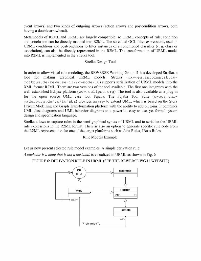
• Derivation rules are represented graphically as a circle with an internal label "DR" and a rule identifier attached to it. Incoming arrows represent conditions, outgoing arrows represent conclusions (see Fig. 6).
• Production rules are represented graphically as a circle with an internal label "PR" and a rule identifier attached to it. Incoming arrows represent conditions, outgoing arrows with a double arrowhead represent actions, referring either to a class or to an activity (see Fig. 7).
• Reaction rules are represented graphically as a circle with an internal label "RR" and a rule identifier attached to it.
In derivation rules conclusion arrows also refer to a classifier model element. Its meaning is to state that the predicate represented by the conclusion classifier applies to any instance that satisfies all rule conditions. In reaction rules there are two kinds of incoming arrows (condition arrows and
event arrows) and two kinds of outgoing arrows (action arrows and postcondition arrows, both having a double arrowhead).
Metamodels of R2ML and URML are largely compatible, so URML concepts of rule, condition and conclusion can be directly mapped into R2ML. The so-called OCL filter expressions, used in URML conditions and postconditions to filter instances of a conditioned classifier (e. g. class or association), can also be directly represented in the R2ML. The transformation of URML model into R2ML is implemented in the Strelka tool.
Strelka Design Tool
In order to allow visual rule modeling, the REWERSE Working Group I1 has developed Strelka, a tool for making graphical URML models. Strelka (oxygen.informatik.tu-cottbus.de/rewerse-i1/?q=node/10) supports serialization of URML models into the XML format R2ML. There are two versions of the tool available. The first one integrates with the well established Eclipse platform (www.eclipse.org). The tool is also available as a plug-in for the open source UML case tool Fujaba. The Fujaba Tool Suite (wwwcs.uni-paderborn.de/cs/fujaba) provides an easy to extend UML, which is based on the Story Driven Modelling and Graph Transformation platform with the ability to add plug-ins. It combines UML class diagrams and UML behavior diagrams to a powerful, easy to use, yet formal system design and specification language.
Strelka allows to capture rules in the semi-graphical syntax of URML and to serialize the URML rule expressions in the R2ML format. There is also an option to generate specific rule code from the R2ML representation for one of the target platforms such as Jena Rules, JBoss Rules.
Rule Models Example
Let us now present selected rule model examples. A simple derivation rule:
A bachelor is a male that is not a husband. is visualized in URML as shown in Fig. 6
FIGURE 6: DERIVATION RULE IN URML (SEE THE REWERSE WG I1 WEBSITE)

A production rule
If car is new, then increase premium by $400.
is modeled in URML as shown in Fig. 7. This model is serialized to the R2ML notation as shown below:
<r2ml:ProductionRuleSet r2ml:ruleSetID="UServProductionRulesSet" xmlns:r2ml="http://www.rewerse.net/I1/2006/R2ML" xmlns:xs="http://www.w3.org/2001/XMLSchema" xmlns:userv="http://www.businessrulesforum.com/2005/userv#" xmlns:op="http://www.xpath2operations.org/op#" xmlns:swrlb="http://www.w3.org/2003/11/swrlb">
<r2ml:ProductionRule r2ml:ruleID="AP_04"> <r2ml:conditions> <r2ml:AttributionAtom r2ml:attributeID="userv.Car.newCar"> <r2ml:subject> <r2ml:ObjectVariable r2ml:name="car" r2ml:classID="userv:Car"/> </r2ml:subject> <r2ml:dataValue> <r2ml:TypedLiteral r2ml:datatypeID="xs:boolean" r2ml:lexicalValue="true"/> </r2ml:dataValue> </r2ml:AttributionAtom> </r2ml:conditions> <r2ml:producedAction> <r2ml:AssignActionExpression r2ml:propertyID="userv:VehicleInsurancePolicy.premium"> <r2ml:contextArgument> <r2ml:ObjectVariable r2ml:name="vehicleInsurancePolicy" r2ml:classID="userv:VehicleInsurancePolicy"/> </r2ml:contextArgument> <r2ml:DatatypeFunctionTerm r2ml:datatypeFunctionID="op:numeric-add"> <r2ml:dataArguments> <r2ml:AttributeFunctionTerm r2ml:attributeID="userv:VehicleInsurancePolicy.premium"> <r2ml:contextArgument> <r2ml:ObjectVariable r2ml:name="vehicleInsurancePolicy" r2ml:classID="userv:VehicleInsurancePolicy"/> </r2ml:contextArgument> </r2ml:AttributeFunctionTerm> <r2ml:TypedLiteral r2ml:lexicalValue="400" r2ml:datatypeID="xs:integer"/> </r2ml:dataArguments> </r2ml:DatatypeFunctionTerm> </r2ml:AssignActionExpression> </r2ml:producedAction> </r2ml:ProductionRule>
<r2ml:ProductionRuleSet>
The serialization can be done automatically by the Strelka tool. Using the provided translators the JBossRules representation is as follows: no-loop true agenda-group "auto_premiums" when $car:Car(newCar == true, $carPremium:premium) then

$car.setPremium($carPremium.doubleValue() + 400); modify($car); end
The whole UServ (BRForumBRForum2005) case study can be found at oxygen.informatik.tucottbus.de/userv.
FIGURE 7: PRODUCTION RULE IN URML (SEE THE REWERSE WG I1 WEBSITE)
Summary
The approach presented in this section addresses some important rule modeling process requirements identified previously. It offers a visual representation of rules that facilitates the use of rule-based technologies. It shows that even with a relatively small and simple extension of UML metamodel, rule modeling can be implemented. It allows for connecting widely used OMG MOF methodologies with emerging Semantic Web technologies. UML case tools with support for rules may be used for modeling of Semantic Web applications, which include ontologies and rules. The proposed method for visual rules modeling and verbalization introduces the possibility for rule-based software development, which is a powerful paradigm for special classes of software applications.
This approach focuses on modeling different kinds of rules, with a visual representation transparently presenting single rules. This representation is defined in terms of MOF and remains coherent with UML. The rule execution model close to classic rule engines, as well as the translation facilities allow for direct modeling of rules for number of systems.
However, some limitations can also be pointed out. The visual representation provided by the URML while transparent, does not scale up to larger rule sets. Currently, there is no clear support for an on-line verification of the R2ML/URML-based rules.

HEKATE APPROACH
In this part a short introduction to rule modeling provided by the HeKatE project is given (hekate.ia.agh.edu.pl). A principal idea in this approach is to model, represent, and store the logic behind the software (sometimes referred to as business logic) using advanced knowledge representation methods taken from knowledge engineering. The logic is then encoded with use of a declarative representation. The logic core would be then embedded into a business application, or an embedded control system. The remaining parts of the business or control applications, such as interfaces, or presentation aspects, would be developed with a classic object-oriented or procedural programming languages such as Java or C. The HeKatE project should eventually provide a coherent runtime environment for running the combined Prolog and Java code. The project officially ends in November 2009.
Objectives
Some of the main goals of HeKatE are to provide an integrated design and implementation process, thus closing the semantic gap in the system design and implementation (Mellor & Balcer, 2002), and automating the implementation, providing an executable solution, that includes an on-line formal analysis of the model, during the design.
HeKatE uses methods and tools in the areas of:
• knowledge representation, for the visual design,
• knowledge translation, for the automated implementation,
• knowledge analysis, for the formal verification.
The approach is based on the classic knowledge engineering concepts.
HeKatE Rule Language
In the HeKatE project an extended rule language is proposed. It is based on the original XTT (eXtended Tabular Trees) language described in (Nalepa & Ligęza, 2005b). The version used in the project is called XTT^2 (referred here as XTT). The XTT rule language is based on the classic concepts of rule languages for rule-based systems (Liebowitz, 1998, Ligęza, 2006), with certain important extensions and features, such as: strong formal foundation based on attributive logic, explicit rulebase structurization, extended rule semantics.
In XTT there is a strong assumption, that the rule base is explicitly structured. The rules with same sets of attributes are grouped within decision tables. On the rule level explicit inference control is allowed. In this way, a set of tables is interconnected using links, corresponding to inference control. This makes up a decision-tree like structure, with tables in the tree nodes. In a general case, the XTT is a graph, with cycles optionally allowed. Let us now move to attributive logic that provides a formal foundation for the rule language.
Attributive logics (AL) constitute a simple but widely-used tool for knowledge specification and inference. In fact in a large variety of applications in various areas of Artificial Intelligence (AI) (Russell & Norvig, 2003) and Knowledge Engineering (KE) attributive languages constitute the

core knowledge representation formalism. The most typical areas of applications include rule-based systems (Liebowitz, 1998, Ligęza, 2006), expert systems (ones based on rule formalism) (Jackson, 1999, Torsun, 1995) and advanced database and data warehouse systems with knowledge discovery applications (Klösgen & Zytkow, 2002) and contemporary business rules and business intelligence components (e.g. Jess, Drools).
The very basic idea in Set Attributive Logic (SAL) is that attributes can take atomic or set values. After (Ligęza, 2006) it is assumed that the atomic formulae of SAL can have three forms, where the attribute takes single value, all the values of given set (the so-called internal conjunction), and some of the values of a given set (the so-called internal disjunction). ALSV(FD) (Attributive logic with Set Values over Finite Domains) has been introduced with practical applications for rule languages in mind. In fact, the primary aim of the presented language is to extend the notational possibilities and expressive power of the XTT-based tabular rule-based systems. XTT rules use ALSV(FD) for the formulation of the rule condition.
Knowledge representation with XTT incorporates extended attributive table format. Further, similar rules are grouped within separated tables, and the whole system is split into such tables linked by arrows representing the control strategy. Consider a set of m rules incorporating the same attributes A1, A2,...,An. In such a case the preconditions can be grouped together and form a regular matrix. Together with the conclusion part this can be expressed as a decision table with rules having attributes A1...An as table rows.
Rule Prototyping
The first stage in HeKatE rule modelling process is rule prototyping. The ARD method (Ligęza, 2006, Nalepa & Wojnicki, 2008) aims at capturing relations between attributes in terms of Attributive Logic (Ligęza, 2006). Attributes denote certain system properties. A property is described by one or more attributes. ARD captures functional dependencies among these properties. A simple property is a property described by a single attribute, while a complex property is described by multiple attributes. It is indicated that particular system property depends functionally on other properties. Such dependencies form a directed graph with nodes being properties.
There are two kinds of attributes adapted by ARD: conceptual attributes and physical attributes. A conceptual attribute is an attribute describing some general, abstract aspect of the system to be specified and refined. Conceptual attribute names are capitalized, e.g.: WaterLevel. Conceptual attributes are being finalized during the design process, into possibly multiple physical attributes. A physical attribute is an attribute describing a well-defined, atomic aspect of the system. Names of physical attributes are not capitalized, e.g. theWaterLevelInTank1. Physical attributes cannot be finalized, they are present in the final rules capturing knowledge about the system.
There are two transformations allowed during the ARD design. These are: finalization and split. Finalization transforms a simple property described by a conceptual attribute into a property described by one or more conceptual or physical attributes. It introduces a more specific knowledge about the given property. Split transforms a complex property into a number of properties and defines functional dependencies among them.
During the design process, upon splitting and finalization, the ARD model grows. This growth is expressed by consecutive diagram levels, making the design more and more specific. This constitutes the hierarchical model. Consecutive levels make a hierarchy of more and more detailed

diagrams describing the designed system. The implementation of such hierarchical model is provided through storing the lowest available, most detailed diagram level at any time, and additional information needed to recreate all of the higher levels, the so-called Transformation Process History (TPH). TPH forms a tree-like structure then, denoting what particular property is split into or what attributes a particular property attribute is finalized into.
After the conceptual system design a rule prototyping algorithm is used. The input of the algorithm is the most detailed ARD diagram, that has all of the physical attributes identified (in fact, the algorithm can also be applied to higher level diagrams, generating rules for some parts of the system being designed). The output is a set of rule prototypes in a very general format:
rule: condition attributes | decision attributes
The ARD design method, is supported by a software tool called VARDA (ai.ia.agh.edu.pl/wiki/hekate:varda). It is a purely declarative prototype written in Prolog, that supports automated visualization at any diagram level using GraphViz.
Rule Modeling
The actual rule modeling is carried out with use of the XTT method (Nalepa & Ligęza, 2005b). The main goal of the methodology is to move the design procedure to a logical level, where knowledge specification is based on the use of abstract rule representation. The design can be automatically translated into a low-level Prolog code. On the other hand, selected formal system properties can be automatically analyzed on-line during the design, so that its characteristics are preserved. The generated Prolog code constitutes a prototype implementation of the system. Since it is equivalent to the visual design specification it can be considered an executable specification.
The main idea behind the XTT representation and design method aims at combining selected existing approaches, namely decision trees and decision tables, by building a special hierarchy of Object-Attribute-Tables (Ligęza & Wojnicki & Nalepa, 2001, Ligęza, 2006). It allows for a hierarchical visual representation of the OAT tables linked into tree-like structure, according to the control specification provided. XTT as a design and knowledge representation method offers a transparent, high density knowledge representation as well as a formally defined logical, Prolog-based interpretation, while preserving flexibility with respect to knowledge manipulation.
A prototype CASE tool for the XTT called HQEd has been developed. It supports XTT-based visual design methodology, with an integrated, incremental design and implementation process, providing the possibility of the on-line, incremental, verification of formal properties (see ai.ia.agh.edu.pl/wiki/hekate:hqed).
Rule Model Example
The HeKatE design process can be easily presented using the following example. It is a reworked Thermostat case, found in (Ligęza, 2006, Nalepa & Ligęza, 2005a). The main problem described there is to create a temperature control system for an office.
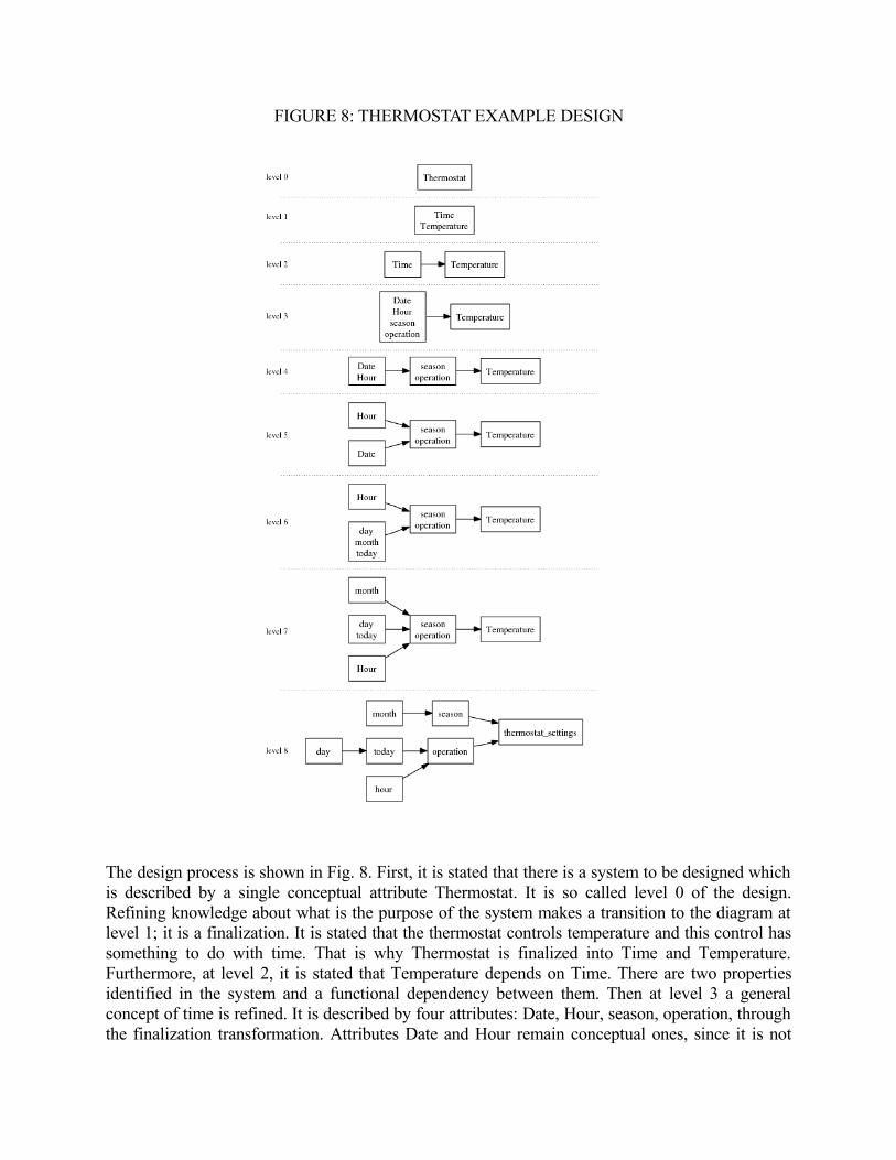
FIGURE 8: THERMOSTAT EXAMPLE DESIGN
The design process is shown in Fig. 8. First, it is stated that there is a system to be designed which is described by a single conceptual attribute Thermostat. It is so called level 0 of the design. Refining knowledge about what is the purpose of the system makes a transition to the diagram at level 1; it is a finalization. It is stated that the thermostat controls temperature and this control has something to do with time. That is why Thermostat is finalized into Time and Temperature. Furthermore, at level 2, it is stated that Temperature depends on Time. There are two properties identified in the system and a functional dependency between them. Then at level 3 a general concept of time is refined. It is described by four attributes: Date, Hour, season, operation, through the finalization transformation. Attributes Date and Hour remain conceptual ones, since it is not

precisely known at this point what exactly they mean, in terms of their representation and perhaps further processing, whereas season and operation are physical attributes. Properties described by such physical attributes cannot be finalized any more. These attributes denote current season and whether the system operates within business hours or not. The design process ends if all properties of the system are described by single physical attributes. At level 5 a split can be observed; it means that Hour is independent from Date.
FIGURE 9: THERMOSTAT TPH DIAGRAM
A complete Transformation Process History diagram is given in Fig. 9. It takes into consideration every transformation. Transformations are expressed by directed edges. Vertices represent property

state before and after the transformation according to the indicated direction. Using the ARD model rule prototypes for XTT are generated, as observed in Fig. 10.
FIGURE 10: RULE PROTOTYPES FOR XTT
The actual rule modeling is carried out with the use of the XTT method within the HQed tool, see Fig. 11. Basing on the rule prototypes XTT table schemes are provided. The tables are filled with rows corresponding to rules. Tables can be linked to control the inference process. Rule analysis features (e.g. completeness check) are provided on-line, during the design (Ligęza & Nalepa, 2005). Using the visual form, a Prolog prototype can be automatically generated, and run using a custom shell.
FIGURE 11: STRUCTURED RULEBASE IN XTT

Summary
The main focus in the HeKatE rule design process is to provide a hierarchical rule modeling method based on classic AI tools, such as decision tables and decision trees. The approach offers a compact rule representation with an expressive rule syntax. It also includes possibility of an automatic translation of the design specification into a low-level code, a well-defined system semantics and the possibility of on-line system verification.
Compared to the REWERSE WGI1 approach it uses AI methods instead of the SE ones. It puts emphasis on the rule base design and structure visualization. Thanks to strong formal foundations it allows for a formal rule analysis. However, at the current stage the integration of this approach with UML-based systems poses more problems than in the case of URML.
MODELING PROCESS FOR RULES
Considering the languages described in this chapter some practical guidelines for an effective modeling process for rules can be given. The process should provide means for:
• building rule vocabularies, identifying concepts, and their semantics,
• determining high-level structure ruleflow, rulebase contexts, allowing for partial rule prototyping,
• building rules capturing the knowledge,
• integrating the ruleset,
• analyzing the quality of the model.
The process should incorporate analysis and verification, as well as means to support practical integration of the rule model. The role of the rule modeling language is crucial in this process.
FUTURE TRENDS
Expected future developments in the area of rule modeling include:
• extended visual rule design,
• tighter integration of the rule model with the application interface,
• integrated early analysis, including validation, and verification,
• semi-automated rule exchange through XML-based formats, including RIF compliance,
• MOF-based solutions for embedding rules into applications designed with UML,
• web services orchestration with rules.
CONCLUSION
In this chapter some classic rule modeling methods were discussed. The focus of the chapter was on the visual rule modeling methods, especially in the field of business rules design.

Currently three strong and influential communities provide different solutions in the field of rule modeling. These are: the classic AI community, advocating extensions of classic AI methods and tools, such as knowledge representation methods and logic programming, the SE community with the OMG as the representing body, with UML language and the MDA framework, the Semantic Web community with W3C as the representing body, providing tools to build and interchange ontologies, and rules build on top of them. At the moment it is unclear what are the final solutions that emerge. It would be beneficial for the rule community if these three communities agree on common rule standards.
REFERENCES
Aalst, W. M. P. van der, Hofstede, A. H. M. ter, & Weske, M. (2003). Business process management:A survey. In Proc. business process management: International conference, bpm 2003, june 26-27, eindhoven, the netherlands (p. 1-12). Springer.
Ben-Ari, M. (2001). Mathematical logic for computer science. London: Springer-Verlag.
Boley, H., Tabet, S., & Wagner, G. (2001). Design rationale of ruleml: A markup language for semantic web rules. In Swws'01. Stanford.
Brachman, R., & Levesque, H. (2004). Knowledge representation and reasoning (1st ed.). Morgan Kaufmann.
Bratko, I. (2000). Prolog programming for articial intelligence (3rd ed.). Addison Wesley.
BRForum. (2005). Userv product derby case study (Tech. Rep.). Business Rules Forum.
Covington, M. A., Nute, D., & Vellino, A. (1996). Prolog programming in depth. Prentice-Hall.
Giarratano, J. C., & Riley, G. D. (2005). Expert systems. Thomson.
Halle, B. von. (2001). Business rules applied: Building better systems using the business rules approach. Wiley.
Harmelen, F. van, Lifschitz, V., & Porter, B. (Eds.). (2007). Handbook of knowledge representation. Elsevier Science.
Herre, H., Jaspars, J. O. M., & Wagner, G. (1995). Partial logics with two kinds of negation as a foundation for knowledge-based reasoning. Centrum voor Wiskunde en Informatica (CWI), 158 , 35.
Horrocks, I., Patel-Schneider, P. F., Boley, H., Tabet, S., Grosof, B., & Dean, M. (2004). Swrl: A semantic web rule language combining owl and ruleml, W3C member submission 21 may 2004 (Tech. Rep.). W3C.
Jackson, P. (1999). Introduction to expert systems (3rd ed.). AddisonWesley. (ISBN 0-201-87686-8)
Karagiannis, D. (1995, August). Bpms: Business process management systems. SIGOIS Bulletin, 16 (1), 10-13.
Klösgen, W., & ytkow, J. M. (Eds.). (2002). Handbook of data mining and knowledge discovery. New York: Oxford University Press.
Lassila, O., & Swick, R. R. (1999). Resource description framework (rdf ) model and syntax specication (Tech. Rep.). World Wide Web Consortium. (www.w3.org/TR/REC-rdf-syntax, W3C Recommendation)
Liebowitz, J. (Ed.). (1998). The handbook of applied expert systems. Boca Raton: CRC Press.
Ligęza, A. (2006). Logical foundations for rule-based systems. Berlin, Heidelberg: Springer-Verlag.

Ligęza, A., & Nalepa, G. J. (2005). Visual design and on-line verication of tabular rule-based systems with xtt. In K. P. Jantke, K.-P. Fähnrich, & W. S. Wittig (Eds.), Marktplatz internet: Von e-learning bis e-payment : 13. leipziger informatik-tage, lit 2005 (pp. 303312). Bonn: Gesellschaft fur Informatik.
Ligęza, A., Wojnicki, I., & Nalepa, G. (2001). Tab-trees: a case tool for design of extended tabular systems. In H. M. et al. (Ed.), Database and expert systems applications (Vol. 2113, p. 422-431). Berlin: Springer-Verlag.
Lukichev, S., & Wagner, G. (2005). Visual rules modeling. In Sixth international andrei ershov memorial conference perspectives of system informatics, novosibirsk, russia, june 2006. Springer.
McGuinness, D. L., & Harmelen, F. van. (2004). Owl web ontology language overview, w3c recommendation 10 february 2004 (Tech. Rep.). W3C.
Mellor, S. J., & Balcer, M. (2002). Executable uml: A foundation for model-driven architectures. Boston, MA, USA: Addison-Wesley Longman Publishing Co., Inc.
Gronau, N, Mueller, C., & Uslar, M. (2004). The kmdl knowlede management approach: Integrating knowledge conversions and business process modeling. In Proc. 5th international conference on practical aspects of knowledge management vienna, austria, 02.12. 2004 (Vol. 3336, p. 1-10). Springer.
Nalepa, G. J., & Ligęza, A. (2005a). Conceptual modelling and automated implementation of rule-based systems. In T. S. Krzysztof Zieliński (Ed.), Software engineering : evolution and emerging technologies (Vol. 130, pp. 330340). Amsterdam: IOS Press.
Nalepa, G. J., & Ligęza, A. (2005b). A graphical tabular model for rule-based logic programming and verication. Systems Science, 31 (2), 8995.
Nalepa, G. J., & Wojnicki, I. (2008). Towards formalization of ARD+ conceptual design and refinement method. In D. C. Wilson & H. C. Lane (Eds.), Flairs-21: Proceedings of thetwenty-rst international Florida artificial intelligence research society conference: 1517 may 2008, coconut grove, Florida, USA (pp. 353-358). Menlo Park, California: AAAI Press.
Object Management Group. (2006, May). Object constraint language version 2.0 (Tech. Rep.). OMG.
OMG. (2006a). Business process modeling notation (bpmn) specification (Tech. Rep. No. dtc/06-02-01). Object Management Group.
OMG. (2006b). Semantics of business vocabulary and business rules (sbvr) (Tech. Rep. No. dtc/06-03-02). Object Management Group.
OMG. (2006c). Object Constraint Language, version 2.0. Object Management Group.
OMG. (2007a). OMG Unified Modeling Language, Infrastructure, V2.1.2. Object Management Group.
OMG. (2007b). Production rule representation beta1 (Tech. Rep.). Object Management Group.
Owen, M., & Raj, J. (2006). Bpmn and business process management. introduction to the new business process modeling standard. (Tech. Rep.). OMG.
Paschke, A. et. al. (2008). Rif use cases and requirements. W3C.
Ross, R. G. (2003). Principles of the business rule approach (1st ed.). Addison-Wesley Professional.
Russell, S., & Norvig, P. (2003). Articial intelligence: A modern approach (2nd ed.). Prentice-Hall.
Sommerville, I. (2004). Software engineering (7th ed.). Pearson Education Limited.
Torsun, I. S. (1995). Foundations of intelligent knowledge-based systems. London, San Diego, New York, Boston, Sydney, Tokyo, Toronto: Academic Press.
W3C. (1998). Extensible markup language (xml) 1.0, w3c recommendation (Tech. Rep.). Author.
Wagner, G., A.Giurca, & Lukichev, S. (2005). R2ml: A general approach for marking up rules. In F. Bry, F. Fages, M. Marchiori, & H. Ohlbach (Eds.), Principles and practices of semantic web reasoning, dagstuhl seminar proceedings 05371.
KEY TERMS AND DEFINITIONS
business rules an approach for applying rule methods in business applications.
decision rule classic example of a knowledge representation method, rule corresponds to a conditional statement.
decision table represents a set of similar rules grouped with respect to used preconditions and conclusions or actions.
decision tree is intuitive way for specifying decision procedures, a simple visual representation (an acyclic, directed graph).
knowledge representation a systematic way of encoding what an expert knows about some domain.
rule modeling designing rules, possibly in a visual way.
PRR Production Rule Representation standard from OMG.
RIF Rule Interchange Format markup from the W3C
SBVR stands for the Semantics of Business Vocabulary and Business Rules specification from OMG.
SWRL The Semantic Web Rule Language is a proposal for a Semantic Web rules language combining sublanguages of OWL and RuleML.
URML UML-Based Rule Modeling Language from the REWERSE WG I1, it extends the UML metamodel with a notion of a rule and defines a visual rule notation.
XTT a hybrid knowledge representation for rules modeling, from the HeKatE project based on the use of decision tables and trees.