laplacian surface editing - igl | interactive … et al. / laplacian surface editing geometry, which...
TRANSCRIPT
Eurographics Symposium on Geometry Processing (2004)R. Scopigno, D. Zorin, (Editors)
Laplacian Surface Editing
O. Sorkine1, D. Cohen-Or1, Y. Lipman1, M. Alexa2, C. Rössl3 and H.-P. Seidel3
1School of Computer Science, Tel Aviv University2Discrete Geometric Modeling Group, Darmstadt University of Technology
3Max-Planck Institut für Informatik, Saarbrücken
AbstractSurface editing operations commonly require geometric details of the surface to be preserved as much as possible.We argue that geometric detail is an intrinsic property of a surface and that, consequently, surface editing is bestperformed by operating over an intrinsic surface representation. We provide such a representation of a surface,based on the Laplacian of the mesh, by encoding each vertex relative to its neighborhood. The Laplacian of themesh is enhanced to be invariant to locally linearized rigid transformations and scaling. Based on this Laplacianrepresentation, we develop useful editing operations: interactive free-form deformation in a region of interestbased on the transformation of a handle, transfer and mixing of geometric details between two surfaces, andtransplanting of a partial surface mesh onto another surface. The main computation involved in all operations isthe solution of a sparse linear system, which can be done at interactive rates. We demonstrate the effectivenessof our approach in several examples, showing that the editing operations change the shape while respecting thestructural geometric detail.
1. IntroductionSurfaces in computer graphics are mostly represented inglobal coordinate systems: explicit representations are basedon points, vertices, or nodes that are typically described us-ing absolute Euclidean coordinates. Implicit representationsdescribe the shape as the level set of a function defined inEuclidean space. A global coordinate system is the naturalchoice for all operations involving other objects, such as ren-dering, intersection computation, transformations, or CSGmodeling. On the other hand, for local surface modeling, itwould be desirable that the representation captures the localshape (i.e. the intrinsic geometry of the surface) rather thanthe absolute position or orientation in Euclidean space.
Manipulating and modifying a surface while preservingthe geometric details is important for various surface edit-ing operations, including free-form deformations [SP86][Coq90], cut and paste [RIKM93, KK99, BMBZ02], fu-sion [KSMK99], morphing [Ale03], and others. The abso-lute position of the mesh vertices is not important for thesetasks, which calls for an intrinsic surface representation.
A partially intrinsic surface mesh representation ismulti-resolution decompositions [FB88, ZSS97, KCVS98][KVS99, GSS99, CGC∗02]. In a multi-resolution mesh, the
geometry is encoded as a base mesh and several levels ofrefinement. The refinement is typically described locally, sothat the geometric details are mostly captured in a discreteset of intrinsic coordinates. Using this representation, sev-eral modeling operations can be performed on an appropriateuser-specified level-of-detail.
Our approach to encoding geometric details is to use dif-ferential coordinates for the vertices. This provides an in-trinsic representation of the surface mesh, where the re-construction of global coordinates always preserves the lo-cal geometry as much as possible given the modeling con-straints. Using a differential representation for editing op-erations has been shown to be quite effective in image do-main [FLW02, PGB03]. Image domain has a natural regularparameterization and a resulting inherent definition of a gra-dient, which allows modeling many editing tasks as a dis-crete Poisson equation. However, this approach cannot bedirectly adapted to discrete (as well as continuous) surfaces.
We rather realize an approach to surface mesh editingbased on encoding each vertex relative to the centroid ofits topological neighbors. The difference of a vertex posi-tion from the centroid of its neighbors is known as a Lapla-cian coordinate [Ale03, KG00, SCOT03, LSCO∗04]. Lapla-cian coordinates are a linear function of the global mesh
c© The Eurographics Association 2004.
Sorkine et al. / Laplacian Surface Editing
geometry, which allows efficient converting between abso-lute and intrinsic representations by solving a sparse linearsystem. Laplacian coordinates are invariant under translation(of absolute geometry), but they are not invariant to scalingand rotation, which poses the main practical problem.
We provide a technique that makes Laplacian coordinatesinvariant to rotation and isotropic scaling. Using this tech-nique, we develop useful surface editing operations, whichpreserve the intrinsic geometry of the surface as much aspossible given the constraints of the modeling operations.The major contributions of this work are:Rotation and scale invariant (RSI) Laplacian coordi-nates:We reformulate the process of least squares fitting ofthe Euclidean geometry to the given Laplacian coordinates.In our fitting process, we implicitly compute an appropriatetransformation per vertex, which is applied to the respectiveLaplacian coordinate. This leads to Laplacian coordinatesthat are almost insensitive to rotation and scaling.Interactive detail-preserving surface editing: Based onthe RSI Laplacian coordinates, we develop an interactiveediting system. The user deforms a region of the surface bymanipulating a handle. The transformation of the handle in-duces a global deformation that resembles the outcome ofmanipulating an object made of some physical soft material.Transfer of geometric detail (coating): Since the detail iscaptured in the Laplacian coordinates, we are able to “peel”high-frequency details from one surface and transfer them toanother. The method can be applied to arbitrary homeomor-phically parameterized surface patches.Transplanting surface patches with homeomorphicboundaries: Our transplanting technique only requires thatthe surfaces have matching topology at the boundaries; thesurface patches within the boundaries need not match. Aseamless transition with gradual change of detail from onepart to another results from blending the Laplacian repre-sentations of the parts.
2. Related workEditing three-dimensional shapes has been an important re-search area in geometric modeling and computer graph-ics. The dominating approach for (free-form) designingof a surface from scratch is based on parametric surfaces(see e.g., [Far92, HL93]), which can be generalized to non-regular base domains using subdivision techniques [SZ00].
However, we are interested in editing an existing sur-face, probably acquired with scanning devices. If the surfaceis smooth, modifications should remain smooth [WW94][Tau95, Le 03]. If the surface contains geometric details(e.g. a sharp feature), these details should be preserved.The editing operation should naturally change the shapeand simultaneously respect the structural detail. The stan-dard approach to detail-preserving modeling operations usesa multi-resolution representation of the mesh. The geomet-ric details are usually expressed relative to a local coordi-nate frame [FB88, ZSS97, KCVS98, KVS99, GSS99]. The
different levels can be considered as frequencies of the ge-ometry. The coarsest level refers to the smoothest surfaceand adding finer levels introduces smaller details. Editingoperations can be performed on coarse levels, and the somodified shape is computed by “adding” the displacementsin their local coordinate frames.
The problem of basis elements with large support in multi-resolution representations has motivated differential repre-sentations for image editing [PGB03]. Note that the com-pletely local and intrinsic differential representation comesat the expense of a global reconstruction computation (e.g.the solution of a global PDE), while the generation of ab-solute coordinates from multi-resolution representations isrestricted to the modified bases.
Our motivation is similar to image editing methods basedon PDEs. We propose a local differential representation, atthe expense of a global reconstruction from differential toabsolute geometry. The modified surface is reconstructed bysolving a sparse linear system. Using state-of-the-art solversthis turns out to be very fast and adequate for interactive sys-tems, even for editing operations on large meshes.
The potential of differential coordinates for free-formmodeling is briefly discussed by Alexa [Ale03]. He specifi-cally discusses the difficulty of deriving affine-invariant co-ordinates for mesh representation as the vertex neighbor-hood may be degenerated (i.e. planar) and, even more diffi-cult, near-degenerate situations make the reconstruction nu-merically intractable.
In a recent work, Yu et al. [YZX∗04] introduce an edit-ing technique, formulated by manipulation of the gradientsof the coordinate functions (x,y,z) defined on the mesh. Thesurface is reconstructed by solving the least-squares systemresulting from discretizing the Poisson equation∆ f = g withDirichlet boundary conditions. Lipman et al. [LSCO∗04] re-construct the surface from discrete Laplacians of the meshfunctions and spatial boundary conditions by solving a verysimilar least-squares system. Both works point out the mainproblem of this approach: the need to rotate the local framesthat define the gradients, or the Laplacians, to preserve theorientation of the local details. They propose to remedythis problem by explicit assignment of the local rotations.Lipman et al. [LSCO∗04] estimate the local rotations ofthe frames on the underlying smooth surface, and Yu etal. [YZX∗04] propagate the rotation of the editing handle,defined by the user, to all the vertices of the region of in-terest. In contrast to these explicit solutions, in this paper weintroduce a method that implicitly transforms the differentialcoordinates based on finding anoptimal transform for eachvertex. The transform is defined by a linear expression oflocal coordinates and a sparse set of control points. The so-lution of this linear system strives to preserve the size and theorientation of the differential coordinates and consequentlyof the surface details.
We focus our work on meshes as they are the dominat-ing representation of surfaces these days. Other surface rep-
c© The Eurographics Association 2004.
Sorkine et al. / Laplacian Surface Editing
resentations are advantageous for certain modeling opera-tions. Implicit surfaces allow easy blending, space warp-ing, and CSG modeling [Roc89, GW95, PASS95, WGG99].The recently popular level-set approach yields a particu-larly simple formulation and implementation of these oper-ations [MBWB02] based on the discrete and regular repre-sentation of a distance field. Adaptively sampled distancefields [FPRJ00] provide a discrete surface representationwith controlled error. All of these essentially implicit rep-resentations allow changing the topology of the surface dur-ing modeling. Point-sampled surfaces are related to meshes;however, explicit information about the topology is missing.This has advantages for some operations [PKKG03], thoughsometimes requires surface reconstruction steps to add morepoints to the representation.
3. Fitting transformed Laplacian coordinatesLet the meshM be described by a pair(K,V), whereK de-scribes the connectivity andV = {v1, . . . ,vn} describes thegeometric positions of the vertices inR3. We use the follow-ing terminology: theneighborhood ringof a vertexi is theset of adjacent verticesNi = { j|(i, j)∈K} and thedegree diof this vertex is the number of elements inNi . We assumethat the mesh is connected.
Instead of using absolute coordinatesV, we would liketo describe the mesh geometry using a set of differentials∆ = {δi}. Specifically, coordinatei will be represented bythe difference betweenvi and the average of its neighbors:
δi = L (vi). (1)
For simplicity, we defineL with uniform weights:
L (vi) = vi −1di
∑j∈Ni
v j . (2)
These weights proved to be sufficient in all our experi-ments. However, our approach does not depend on the par-ticular choice ofL . For instance, the cotangent weights(see, e.g. [DMSB99]) would accommodate extremely non-uniform tessellations, and their application is straightfor-ward. The transformation betweenV and∆ can be describedin matrix algebra. LetA be the mesh adjacency matrix andD = diag(d1, . . . ,dn) be the degree matrix. Then∆ = LV,whereL = I −D−1A for the uniform weights. The matrixL is commonly considered as the Laplacian operator of themesh with connectivityA [Tau95, KG00], which is why wecall δi theLaplacian coordinateof vertexi. Laplacian coor-dinates are invariant under translation, but sensitive to lineartransforms.L has rankn−1, which meansV can be recov-ered from∆ by fixing one vertex and solving a linear system.
The approach to performing modeling operations usingLaplacian coordinates∆ is to fix the absolute position of sev-eral vertices (see [Ale03]), i.e.,
v′i = ui , i ∈ {m, . . . ,n}, m< n (3)
and solve for the remaining vertices{v′i}, i ∈ {1, . . . ,m−1}
by fitting the Laplacian coordinates of the geometryV ′ to thegiven Laplacians∆. It has been observed that the solutionbehaves better if the constraints{ui} are satisfied in a leastsquares sense rather than exactly [SCOT03, LSCO∗04]. Thisresults in the following error functional:
E(V ′) =n
∑i=1
∥∥δi −L (v′i))∥∥2 +
n
∑i=m
‖v′i −ui‖2, (4)
which has to be minimized to find a suitable set of coordi-natesV ′. Solving this quadratic minimization problem re-sults in a sparse linear system of equations.
The rationale of fitting given Laplacian coordinates is thatdetails of the shape are preserved, as the relative locationof vertices is encoded in∆. As mentioned, however, thesecoordinates are sensitive to linear transformations. Thus, thedetail structure of the shape can be translated, but not rotatedor scaled. If the constraintsui imply a linear transform, thedetails are not transformed accordingly.
The main idea of our approach is to compute an appropri-ate transformationTi for each vertexi based on the eventualnew configuration of verticesV ′. Thus,Ti(V
′) is a functionof V ′ and we formulate the error functional as
E(V ′) =n
∑i=1
∥∥Ti(V′)δi −L (v′i)
∥∥2 +n
∑i=m
‖v′i −ui‖2. (5)
Note that in Eq. 5 bothTi andV ′ are unknown. However, ifthe coefficients ofTi are a linear function inV ′, then solvingfor V ′ implies findingTi (though not explicitly) sinceE(V ′)is simply a quadratic function inV ′.
The basic idea for definingTi is to derive it from the trans-formation ofvi and its neighbors intov′i and its neighbors:
minTi
(‖Tivi −v′i‖2 + ∑
j∈Ni
‖Tiv j −v′j‖2
). (6)
Since this is a quadratic expression, the minimizer is a linearfunction ofV ′, as required. However, ifTi is unconstrained,the natural minimizer forE(V ′) is a membrane solution, andall geometric detail is lost. Thus,Ti needs to be constrainedin a reasonable way. We have found thatTi should includerotations, isotropic scales, and translations. In particular, wewant to disallow anisotropic scales, as they allow removingthe normal component from Laplacian coordinates.
The translational part ofTi is introduced simply by us-ing homogeneous coordinates. The linear part should sat-isfy the following conditions: The transformation should bea linear function in the target configuration but constrainedto isotropic scales and rotations. The class of matrices rep-resenting isotropic scales and rotation can be written asT = sexp(H), whereH is a skew-symmetric matrix. In 3D,skew-symmetric matrices emulate a cross product with avector, i.e.Hx = h× x. Drawing upon several other prop-erties of 3×3 skew matrices, one can derive the followingrepresentation of the exponential above:
sexpH = s(αI +βH + γhTh). (7)
c© The Eurographics Association 2004.
Sorkine et al. / Laplacian Surface Editing
Inspecting the terms we find that onlys, I , andH are linear inthe unknownssandh, whilehTh is quadratic As a linear ap-proximation of the class of constrained transformations we,therefore, use
Ti =
s −h3 h2 txh3 s −h1 ty−h2 h1 s tz
0 0 0 1
. (8)
This matrix is a good linear approximation for rotations withsmall angles. The consequences for larger angles are dis-cussed later.
Given the matrixTi as in Eq. 8, we can write down thelinear dependency (cf. Eq. 6) ofTi on V ′, explicitly. Let(si ,hi , t i)
T be the vector of the unknowns inTi . Then wewish to minimize
‖Ai(si ,hi , t i)T −bi‖
2, (9)
whereAi contains the positions ofvi and its neighbors andbi contains the position ofv′i and its neighbors. The structureof (si ,hi , t i)
T yields
Ai =
vkx
0 vkz−vky
1 0 0
vky−vkz
0 vkx0 1 0
vkzvky
−vkx0 0 0 1
...
, k∈{i}∪Ni ,
(10)and
bi =
v′kx
v′ky
v′kz
...
, k∈ {i}∪Ni . (11)
The linear least-squares problem above is solved by
(si ,hi , t i)T =
(AT
i Ai
)−1AT
i bi , (12)
which shows that the coefficients ofTi are linear functionsof bi , sinceAi is known from the initial meshV. The entriesof bi are simply entries ofV ′ so that(si ,hi , t i) and, thus,Tiis a linear function inV ′, as required.
3.1. Adjusting Ti
In many modeling situations, solving for absolute coordi-nates in the way explained above is sufficient. However,there are two exceptions that require adjusting the transfor-mations:
1. As mentioned,Ti does not exactly represent the class ofisotropic scales and rotations. For large anglesφ aroundthe axish/‖h‖ the space is scaled alongh/‖h‖ with afactor of cosφ.
2. Sometimes anisotropic scaling is the wanted free-formdeformation, e.g., the dislocation of a single vertex typi-cally implies a stretch in only one direction.
Both situations are handled in a similar way: The current setof transformations{Ti} is computed fromV andV ′. TheneachTi is inspected, the corresponding Laplacian coordinateδi is updated appropriately depending on the cases above,and the system is solved again. In the case of too large an-gles of rotations, it is possible to first apply an approximatedreconstruction using the method in [LSCO∗04] and then re-fine it with our technique, such that smaller rotations are in-volved. In the case of wanted anisotropic scaling, the{δi}are scaled by the inverse of the scale implied by the con-straints. See Figure 2 for an example of large rotations.
4. Mesh editing
There are many different tools to manipulate an existingmesh. Perhaps the simplest form consists of manipulating ahandle, which is a set of vertices that can be moved, rotatedand scaled by the user. The manipulation of the handle ispropagated to the shape such that the modification is intuitiveand resembles the outcome of manipulating an object madeof some physical soft material. This can be generalized to afree-form deformation tool which transforms a set of controlpoints defining a complex of possibly weighted handles, en-abling other modeling metaphors to be mimicked (see e.g.,the recent work of [BK03] and the references therein).
The editing interaction framework we used is similar tothe one described in [LSCO∗04], which is comprised of thefollowing stages: First, the user defines the region of inter-est (ROI) for editing. The ROI is defined by the closed sim-ple loop of its boundary edges. Next, the handle inside theROI is defined. In addition, the user can optionally definethe amount of “padding” of the ROI bystationary anchors.These stationary anchors form abelt that supports the tran-sition between the ROI and the untouched part of the mesh.Then, the user manipulates the handle, and the surface is re-constructed with respect to the relocation of the handle.
The submesh of the ROI is the only part considered duringthe editing process. The positions of the handle vertices andthe stationary anchors constrain the reconstruction and hencethe shape of the resulting surface. The handle is the means ofuser control, and therefore, its constraints are constantly up-dated. The unconstrained vertices of the submesh are repeat-edly reconstructed to follow the user interaction. The station-ary anchors are responsible for the transition from the ROIto the fixed part of the mesh, resulting in a soft transitionbetween them. Selecting the amount of padding by anchorvertices depends on the user’s requirements, as mentionedabove. We have observed in all our experiments that settingthe radius of the “padding ring” to be up to 10% of the ROIradius gives satisfying results.
The reconstruction of the submesh requires solving thelinear least-squares system as described in Section 3. Build-ing the system matrix (Eq. 12), including the computation ofa sparse factorization, is relatively slow, but constructed onlyonce when the ROI is selected. The user interaction with the
c© The Eurographics Association 2004.
Sorkine et al. / Laplacian Surface Editing
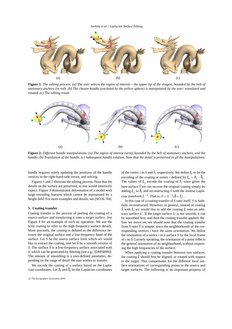
(a) (b) (c)
Figure 1: The editing process. (a) The user selects the region of interest – the upper lip of the dragon, bounded by the belt ofstationary anchors (in red). (b) The chosen handle (enclosed by the yellow sphere) is manipulated by the user: translated androtated. (c) The editing result.
(a) (b) (c)
Figure 2: Different handle manipulations. (a) The region of interest (arm), bounded by the belt of stationary anchors, and thehandle. (b) Translation of the handle. (c) Subsequent handle rotation. Note that the detail is preserved in all the manipulations.
handle requires solely updating the positions of the handlevertices in the right-hand-side vector, and solving.
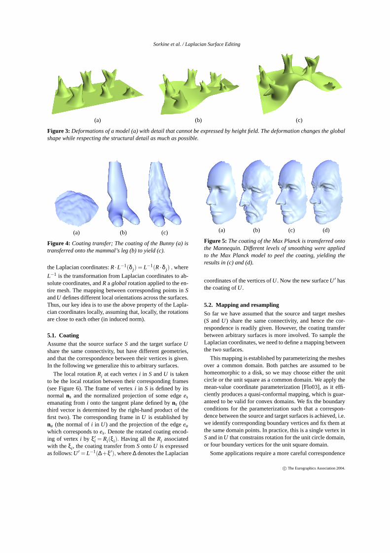
Figures 1 and 2 illustrate the editing process. Note that thedetails on the surface are preserved, as one would intuitivelyexpect. Figure 3 demonstrates deformation of a model withlarge extruding features which cannot be represented by aheight field. For more examples and details, see [SCOL∗04].
5. Coating transferCoating transfer is the process of peeling the coating of asourcesurface and transferring it onto atarget surface. SeeFigure 4 for an example of such an operation. We use theterm coating to refer to the high-frequency surface details.More precisely, the coating is defined as the difference be-tween the original surface and a low-frequency band of thesurface. LetS be the source surface from which we wouldlike to extract the coating, and letSbe a smooth version ofS. The surfaceS is a low-frequency surface associated withS, which can be generated by filtering (see e.g., [DMSB99]).The amount of smoothing is a user-defined parameter, de-pending on the range of detail the user wishes to transfer.
We encode the coating of a surface based on the Lapla-cian coordinates. Letδi andδi be the Laplacian coordinates
of the vertexi in SandS, respectively. We defineξi to be theencoding of the coating at vertexi defined byξi = δi − δi .The values ofξ j encode the coating ofS, since given the
bare surfaceSwe can recover the original coating simply byaddingξ j to δi and reconstructingSwith the inverse Lapla-
cian transformL−1. That is,S= L−1(δ+ξ) .
In this case of a coating transfer ofSonto itself,S is faith-fully reconstructed. However, in general, instead of coatingS with ξ, we would like to add the coatingξ onto an arbi-trary surfaceU . If the target surfaceU is not smooth, it canbe smoothed first, and then the coating transfer applied. Be-fore we move on, we should note that the coating transferfrom SontoS is simple, since the neighborhoods of the cor-responding verticesi have the sameorientation. We definethe orientation of a vertexi in a surfaceSby the local frameof i onS. Loosely speaking, the orientation of a point reflectsthe general orientation of its neighborhood, without respect-ing the high frequencies of the surface.
When applying a coating transfer between two surfaces,the coatingξ should first be aligned, or rotated with respectto the target. This compensates for the different local sur-face orientations of corresponding points in the source andtarget surfaces. The following is an important property of
c© The Eurographics Association 2004.
Sorkine et al. / Laplacian Surface Editing
(a) (b) (c)
Figure 3: Deformations of a model (a) with detail that cannot be expressed by height field. The deformation changes the globalshape while respecting the structural detail as much as possible.
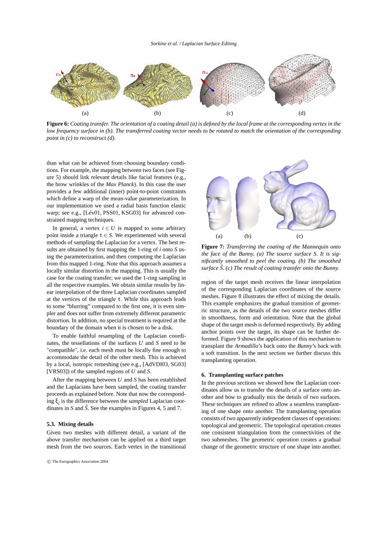
(a) (b) (c)
Figure 4: Coating transfer; The coating of the Bunny (a) istransferred onto the mammal’s leg (b) to yield (c).
the Laplacian coordinates:R·L−1(δ j ) = L−1(R·δ j ) , where
L−1 is the transformation from Laplacian coordinates to ab-solute coordinates, andRaglobal rotation applied to the en-tire mesh. The mapping between corresponding points inSandU defines different local orientations across the surfaces.Thus, our key idea is to use the above property of the Lapla-cian coordinates locally, assuming that, locally, the rotationsare close to each other (in induced norm).
5.1. CoatingAssume that the source surfaceS and the target surfaceUshare the same connectivity, but have different geometries,and that the correspondence between their vertices is given.In the following we generalize this to arbitrary surfaces.
The local rotationRi at each vertexi in SandU is takento be the local rotation between their corresponding frames(see Figure 6). The frame of vertexi in S is defined by itsnormal ns and the normalized projection of some edgeesemanating fromi onto the tangent plane defined byns (thethird vector is determined by the right-hand product of thefirst two). The corresponding frame inU is established bynu (the normal ofi in U) and the projection of the edgeeu
which corresponds toes. Denote the rotated coating encod-ing of vertexi by ξ′i = Ri(ξi). Having all theRi associatedwith theξi , the coating transfer fromSontoU is expressedas follows:U ′ = L−1(∆+ξ′), where∆ denotes the Laplacian
(a) (b) (c) (d)
Figure 5: The coating of the Max Planck is transferred ontothe Mannequin. Different levels of smoothing were appliedto the Max Planck model to peel the coating, yielding theresults in (c) and (d).
coordinates of the vertices ofU . Now the new surfaceU ′ hasthe coating ofU .
5.2. Mapping and resampling
So far we have assumed that the source and target meshes(S andU) share the same connectivity, and hence the cor-respondence is readily given. However, the coating transferbetween arbitrary surfaces is more involved. To sample theLaplacian coordinates, we need to define a mapping betweenthe two surfaces.
This mapping is established by parameterizing the meshesover a common domain. Both patches are assumed to behomeomorphic to a disk, so we may choose either the unitcircle or the unit square as a common domain. We apply themean-value coordinate parameterization [Flo03], as it effi-ciently produces a quasi-conformal mapping, which is guar-anteed to be valid for convex domains. We fix the boundaryconditions for the parameterization such that a correspon-dence between the source and target surfaces is achieved, i.e.we identify corresponding boundary vertices and fix them atthe same domain points. In practice, this is a single vertex inSand inU that constrains rotation for the unit circle domain,or four boundary vertices for the unit square domain.
Some applications require a more careful correspondence
c© The Eurographics Association 2004.
Sorkine et al. / Laplacian Surface Editing
(a) (b) (c) (d)
Figure 6: Coating transfer. The orientation of a coating detail (a) is defined by the local frame at the corresponding vertex in thelow frequency surface in (b). The transferred coating vector needs to be rotated to match the orientation of the correspondingpoint in (c) to reconstruct (d).
than what can be achieved from choosing boundary condi-tions. For example, the mapping between two faces (see Fig-ure 5) should link relevant details like facial features (e.g.,the brow wrinkles of theMax Planck). In this case the userprovides a few additional (inner) point-to-point constraintswhich define a warp of the mean-value parameterization. Inour implementation we used a radial basis function elasticwarp; see e.g., [Lév01, PSS01, KSG03] for advanced con-strained mapping techniques.
In general, a vertexi ∈ U is mapped to some arbitrarypoint inside a triangleτ ∈ S. We experimented with severalmethods of sampling the Laplacian for a vertex. The best re-sults are obtained by first mapping the 1-ring ofi ontoSus-ing the parameterization, and then computing the Laplacianfrom this mapped 1-ring. Note that this approach assumes alocally similar distortion in the mapping. This is usually thecase for the coating transfer; we used the 1-ring sampling inall the respective examples. We obtain similar results by lin-ear interpolation of the three Laplacian coordinates sampledat the vertices of the triangleτ. While this approach leadsto some “blurring” compared to the first one, it is even sim-pler and does not suffer from extremely different parametricdistortion. In addition, no special treatment is required at theboundary of the domain when it is chosen to be a disk.
To enable faithful resampling of the Laplacian coordi-nates, the tessellations of the surfacesU andS need to be"compatible", i.e. each mesh must be locally fine enough toaccommodate the detail of the other mesh. This is achievedby a local, isotropic remeshing (see e.g., [AdVDI03, SG03][VRS03]) of the sampled regions ofU andS.
After the mapping betweenU andShas been establishedand the Laplacians have been sampled, the coating transferproceeds as explained before. Note that now the correspond-ing ξi is the difference between thesampledLaplacian coor-dinates inSandS. See the examples in Figures 4, 5 and 7.
5.3. Mixing detailsGiven two meshes with different detail, a variant of theabove transfer mechanism can be applied on a third targetmesh from the two sources. Each vertex in the transitional
(a) (b) (c)
Figure 7: Transferring the coating of the Mannequin ontothe face of the Bunny. (a) The source surface S. It is sig-nificantly smoothed to peel the coating. (b) The smoothedsurfaceS. (c) The result of coating transfer onto the Bunny.
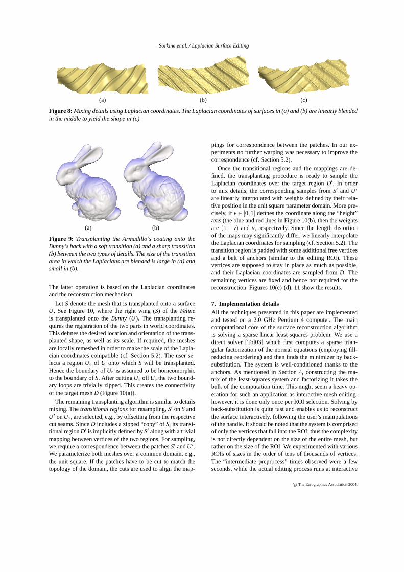
region of the target mesh receives the linear interpolationof the corresponding Laplacian coordinates of the sourcemeshes. Figure 8 illustrates the effect of mixing the details.This example emphasizes the gradual transition of geomet-ric structure, as the details of the two source meshes differin smoothness, form and orientation. Note that the globalshape of the target mesh is deformed respectively. By addinganchor points over the target, its shape can be further de-formed. Figure 9 shows the application of this mechanism totransplant theArmadillo’s back onto theBunny’s back witha soft transition. In the next section we further discuss thistransplanting operation.
6. Transplanting surface patchesIn the previous sections we showed how the Laplacian coor-dinates allow us to transfer the details of a surface onto an-other and how to gradually mix the details of two surfaces.These techniques are refined to allow a seamless transplant-ing of one shape onto another. The transplanting operationconsists of two apparently independent classes of operations:topological and geometric. The topological operation createsone consistent triangulation from the connectivities of thetwo submeshes. The geometric operation creates a gradualchange of the geometric structure of one shape into another.
c© The Eurographics Association 2004.
Sorkine et al. / Laplacian Surface Editing
(a) (b) (c)
Figure 8: Mixing details using Laplacian coordinates. The Laplacian coordinates of surfaces in (a) and (b) are linearly blendedin the middle to yield the shape in (c).
(a) (b)
Figure 9: Transplanting the Armadillo’s coating onto theBunny’s back with a soft transition (a) and a sharp transition(b) between the two types of details. The size of the transitionarea in which the Laplacians are blended is large in (a) andsmall in (b).
The latter operation is based on the Laplacian coordinatesand the reconstruction mechanism.
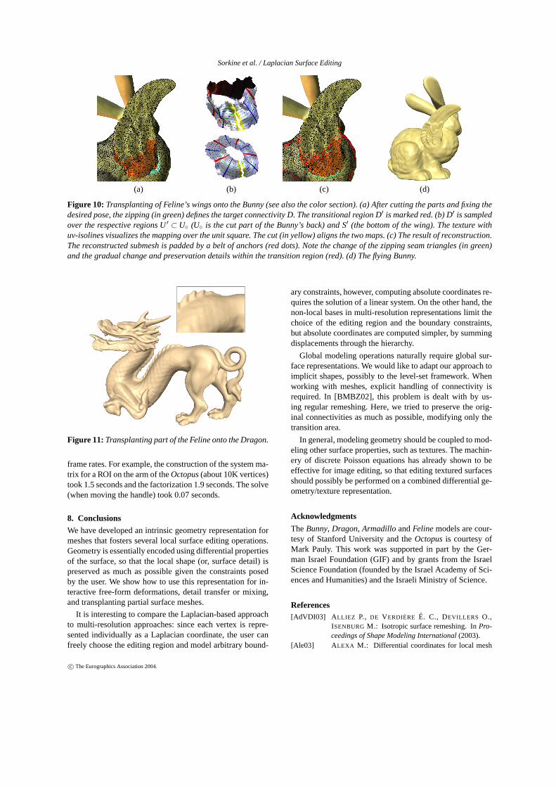
Let S denote the mesh that is transplanted onto a surfaceU . See Figure 10, where the right wing (S) of the Felineis transplanted onto theBunny (U). The transplanting re-quires the registration of the two parts in world coordinates.This defines the desired location and orientation of the trans-planted shape, as well as its scale. If required, the meshesare locally remeshed in order to make the scale of the Lapla-cian coordinates compatible (cf. Section 5.2). The user se-lects a regionU◦ of U onto whichS will be transplanted.Hence the boundary ofU◦ is assumed to be homeomorphicto the boundary ofS. After cuttingU◦ off U , the two bound-ary loops are trivially zipped. This creates the connectivityof the target meshD (Figure 10(a)).
The remaining transplanting algorithm is similar to detailsmixing. Thetransitional regionsfor resampling,S′ onSandU ′ onU◦, are selected, e.g., by offsetting from the respectivecut seams. SinceD includes a zipped “copy” ofS, its transi-tional regionD′ is implicitly defined byS′ along with a trivialmapping between vertices of the two regions. For sampling,we require a correspondence between the patchesS′ andU ′.We parameterize both meshes over a common domain, e.g.,the unit square. If the patches have to be cut to match thetopology of the domain, the cuts are used to align the map-
pings for correspondence between the patches. In our ex-periments no further warping was necessary to improve thecorrespondence (cf. Section 5.2).
Once the transitional regions and the mappings are de-fined, the transplanting procedure is ready to sample theLaplacian coordinates over the target regionD′. In orderto mix details, the corresponding samples fromS′ andU ′
are linearly interpolated with weights defined by their rela-tive position in the unit square parameter domain. More pre-cisely, if v∈ [0,1] defines the coordinate along the “height”axis (the blue and red lines in Figure 10(b), then the weightsare (1− v) and v, respectively. Since the length distortionof the maps may significantly differ, we linearly interpolatethe Laplacian coordinates for sampling (cf. Section 5.2). Thetransition region is padded with some additional free verticesand a belt of anchors (similar to the editing ROI). Thesevertices are supposed to stay in place as much as possible,and their Laplacian coordinates are sampled fromD. Theremaining vertices are fixed and hence not required for thereconstruction. Figures 10(c)-(d), 11 show the results.
7. Implementation detailsAll the techniques presented in this paper are implementedand tested on a 2.0 GHz Pentium 4 computer. The maincomputational core of the surface reconstruction algorithmis solving a sparse linear least-squares problem. We use adirect solver [Tol03] which first computes a sparse trian-gular factorization of the normal equations (employing fill-reducing reordering) and then finds the minimizer by back-substitution. The system is well-conditioned thanks to theanchors. As mentioned in Section 4, constructing the ma-trix of the least-squares system and factorizing it takes thebulk of the computation time. This might seem a heavy op-eration for such an application as interactive mesh editing;however, it is done only once per ROI selection. Solving byback-substitution is quite fast and enables us to reconstructthe surface interactively, following the user’s manipulationsof the handle. It should be noted that the system is comprisedof only the vertices that fall into the ROI; thus the complexityis not directly dependent on the size of the entire mesh, butrather on the size of the ROI. We experimented with variousROIs of sizes in the order of tens of thousands of vertices.The “intermediate preprocess” times observed were a fewseconds, while the actual editing process runs at interactive
c© The Eurographics Association 2004.
Sorkine et al. / Laplacian Surface Editing
(a) (b) (c) (d)
Figure 10: Transplanting of Feline’s wings onto the Bunny (see also the color section). (a) After cutting the parts and fixing thedesired pose, the zipping (in green) defines the target connectivity D. The transitional region D′ is marked red. (b) D′ is sampledover the respective regions U′ ⊂U◦ (U◦ is the cut part of the Bunny’s back) and S′ (the bottom of the wing). The texture withuv-isolines visualizes the mapping over the unit square. The cut (in yellow) aligns the two maps. (c) The result of reconstruction.The reconstructed submesh is padded by a belt of anchors (red dots). Note the change of the zipping seam triangles (in green)and the gradual change and preservation details within the transition region (red). (d) The flying Bunny.
Figure 11:Transplanting part of the Feline onto the Dragon.
frame rates. For example, the construction of the system ma-trix for a ROI on the arm of theOctopus(about 10K vertices)took 1.5 seconds and the factorization 1.9 seconds. The solve(when moving the handle) took 0.07 seconds.
8. Conclusions
We have developed an intrinsic geometry representation formeshes that fosters several local surface editing operations.Geometry is essentially encoded using differential propertiesof the surface, so that the local shape (or, surface detail) ispreserved as much as possible given the constraints posedby the user. We show how to use this representation for in-teractive free-form deformations, detail transfer or mixing,and transplanting partial surface meshes.
It is interesting to compare the Laplacian-based approachto multi-resolution approaches: since each vertex is repre-sented individually as a Laplacian coordinate, the user canfreely choose the editing region and model arbitrary bound-
ary constraints, however, computing absolute coordinates re-quires the solution of a linear system. On the other hand, thenon-local bases in multi-resolution representations limit thechoice of the editing region and the boundary constraints,but absolute coordinates are computed simpler, by summingdisplacements through the hierarchy.
Global modeling operations naturally require global sur-face representations. We would like to adapt our approach toimplicit shapes, possibly to the level-set framework. Whenworking with meshes, explicit handling of connectivity isrequired. In [BMBZ02], this problem is dealt with by us-ing regular remeshing. Here, we tried to preserve the orig-inal connectivities as much as possible, modifying only thetransition area.
In general, modeling geometry should be coupled to mod-eling other surface properties, such as textures. The machin-ery of discrete Poisson equations has already shown to beeffective for image editing, so that editing textured surfacesshould possibly be performed on a combined differential ge-ometry/texture representation.
Acknowledgments
TheBunny, Dragon, Armadillo andFelinemodels are cour-tesy of Stanford University and theOctopusis courtesy ofMark Pauly. This work was supported in part by the Ger-man Israel Foundation (GIF) and by grants from the IsraelScience Foundation (founded by the Israel Academy of Sci-ences and Humanities) and the Israeli Ministry of Science.
References[AdVDI03] A LLIEZ P., DE VERDIÈRE É. C., DEVILLERS O.,
ISENBURGM.: Isotropic surface remeshing. InPro-ceedings of Shape Modeling International(2003).
[Ale03] ALEXA M.: Differential coordinates for local mesh
c© The Eurographics Association 2004.
Sorkine et al. / Laplacian Surface Editing
morphing and deformation.The Visual Computer 19,2 (2003), 105–114.
[BK03] BENDELS G. H., KLEIN R.: Mesh forging: editingof 3d-meshes using implicitly defined occluders. InProceedings of the EG Symposium on Geometry Pro-cessing(2003), pp. 207–217.
[BMBZ02] B IERMANN H., MARTIN I., BERNARDINI F., ZORIN
D.: Cut-and-paste editing of multiresolution surfaces.In Proceedings of SIGGRAPH 2002, pp. 312–321.
[CGC∗02] CAPELL S., GREEN S., CURLESSB., DUCHAMP T.,POPOVIC Z.: A multiresolution framework for dy-namic deformations. InProceedings of the EG Sym-posium on Computer Animation 2002, pp. 41–47.
[Coq90] COQUILLART S.: Extended free-form deformation: Asculpturing tool for 3D geometric modeling. InPro-ceedings of SIGGRAPH 90, pp. 187–196.
[DMSB99] DESBRUN M., MEYER M., SCHRÖDER P., BARR
A. H.: Implicit fairing of irregular meshes using diffu-sion and curvature flow. InProceedings of SIGGRAPH99, pp. 317–324.
[Far92] FARIN G.: Curves and surfaces for computer aidedgeometric design: a practical guide. Academic Press,1992.
[FB88] FORSEY D., BARTELS R.: Hierarchical b-spline re-finement. InProceedings of SIGGRAPH 88.
[Flo03] FLOATER M. S.: Mean-value coordinates.ComputerAided Geometric Design 20(2003), 19–27.
[FLW02] FATTAL R., LISCHINSKI D., WERMAN M.: Gradientdomain high dynamic range compression. InProceed-ings of SIGGRAPH 2002, pp. 249–256.
[FPRJ00] FRISKEN S. F., PERRY R. N., ROCKWOOD A. P.,JONES T. R.: Adaptively sampled distance fields: Ageneral representation of shape for computer graphics.In Proceedings of SIGGRAPH 2000, pp. 249–254.
[GSS99] GUSKOV I., SWELDENS W., SCHRÖDER P.: Mul-tiresolution signal processing for meshes. InProceed-ings of SIGGRAPH 99, pp. 325–334.
[GW95] GUY A., WYVIL B.: Controlled blending for implicitsurfaces. InImplicit Surfaces ’95.
[HL93] HOSCHEK J., LASSER D.: Fundamentals of Com-puter Aided Geometric Design. A.K. Peters, 1993.
[KCVS98] KOBBELT L., CAMPAGNA S., VORSATZ J., SEIDEL
H.-P.: Interactive multi-resolution modeling on arbi-trary meshes. InProceedings of SIGGRAPH 98.
[KG00] KARNI Z., GOTSMAN C.: Spectral compression ofmesh geometry. InProceedings of SIGGRAPH 2000.
[KK99] K URIYAMA S., KANEKO T.: Discrete parametriza-tion for deforming arbitrary meshes. InGraphics In-terface ’99, pp. 132–139.
[KSG03] KRAEVOY V., SHEFFER A., GOTSMAN C.: Match-maker: constructing constrained texture maps. InPro-ceedings of SIGGRAPH 2003, pp. 326–333.
[KSMK99] K ANAI T., SUZUKI H., MITANI J., KIMURA F.: In-teractive mesh fusion based on local 3D metamorpho-sis. InGraphics Interface ’99, pp. 148–156.
[KVS99] KOBBELT L., VORSATZ J., SEIDEL H.-P.: Multires-olution hierarchies on unstructured triangle meshes.Computational Geometry: Theory and Applications14 (1999), 5–24.
[Le 03] LE VEUVRE L.: Modelling and deformation of sur-faces defined over finite elements. InProceedings ofShape Modeling International(2003), pp. 175–183.
[Lév01] LÉVY B.: Constrained texture mapping for polygonalmeshes. InProceedings of SIGGRAPH 2001.
[LSCO∗04] LIPMAN Y., SORKINE O., COHEN-OR D., LEVIN
D., RÖSSL C., SEIDEL H.-P.: Differential coordi-nates for interactive mesh editing. InProceedings ofShape Modeling International(2004).
[MBWB02] M USETHK., BREEND. E., WHITAKER R. T., BARR
A. H.: Level set surface editing operators. InProceed-ings of SIGGRAPH 2002, pp. 330–338.
[PASS95] PASKO A., ADZHIEV V., SOURIN A., SAVCHENKO
V.: Function representation in geometric modeling:concepts, implementation and applications.The VisualComputer 11, 8 (1995), 429–446.
[PGB03] PÉREZ P., GANGNET M., BLAKE A.: Poisson imageediting. InProceedings of SIGGRAPH 2003.
[PKKG03] PAULY M., KEISER R., KOBBELT L. P., GROSSM.:Shape modeling with point-sampled geometry. InPro-ceedings of SIGGRAPH 2003, pp. 641–650.
[PSS01] PRAUN E., SWELDENS W., SCHRÖDER P.: Consis-tent mesh parameterizations. InProceedings of SIG-GRAPH 2001, pp. 179–184.
[RIKM93] RANTA M., INUI M., K IMURA F., MÄNTYLÄ M.:Cut and paste based modeling with boundary features.In Proceedings of Solid Modeling(1993).
[Roc89] ROCKWOOD A. P.: The displacement method for im-plicit blending surfaces in solid models.ACM Trans-actions on Graphics 8, 4 (Oct. 1989), 279–297.
[SCOL∗04] SORKINE O., COHEN-OR D., LIPMAN Y., ALEXA
M., RÖSSL C., SEIDEL H.-P.: Laplacian SurfaceEditing. Technical report, Tel Aviv University, 2004.
[SCOT03] SORKINE O., COHEN-OR D., TOLEDO S.: High-passquantization for mesh encoding. InProceedings of theEG Symposium on Geometry Processing(2003).
[SG03] SURAZHSKY V., GOTSMAN C.: Explicit surfaceremeshing. InProceedings of the EG Symposium onGeometry Processing(2003), pp. 17–28.
[SP86] SEDERBERGT. W., PARRY S. R.: Free-form defor-mation of solid geometric models. InProceedings ofSIGGRAPH 86, pp. 151–160.
[SZ00] SCHRÖDERP., ZORIN D.: Subdivision for modelingand animation. InSIGGRAPH 2000 Course Notes.
[Tau95] TAUBIN G.: A signal processing approach to fair sur-face design. InProceedings of SIGGRAPH 95.
[Tol03] TOLEDO S.: TAUCS: A Library of Sparse Lin-ear Solvers, version 2.2. Available online athttp://www.tau.ac.il/∼stoledo/taucs/, Sept. 2003.
[VRS03] VORSATZ J., RÖSSL C., SEIDEL H.-P.: Dynamicremeshing and applications. InProceedings SolidModeling(2003), pp. 167–175.
[WGG99] WYVILL B., GUY A., GALIN E.: Extending the CSGtree: warping, blending and boolean operations in animplicit surface modeling system.Computer GraphicsForum 18, 2 (June 1999), 149–158.
[WW94] WELCH W., WITKIN A.: Free–Form shape designusing triangulated surfaces. InProceedings of SIG-GRAPH 94, pp. 247–256.
[YZX ∗04] YU Y., ZHOU K., XU D., SHI X., BAO H., GUO B.,SHUM H.-Y.: Mesh editing with Poisson-based gradi-ent field manipulation. InProceedings of SIGGRAPH2004 (to appear).
[ZSS97] ZORIN D., SCHRÖDER P., SWELDENS W.: Interac-tive multiresolution mesh editing. InProceedings ofSIGGRAPH 97, pp. 259–268.
c© The Eurographics Association 2004.