large conductor power cables – ac resistance …
TRANSCRIPT

LARGE CONDUCTOR POWER CABLES – AC RESISTANCE MEASUREMENT WITH VARIABLE FREQUENCY
G. Schröder1, J. Kaumanns
1, R. Plath
2
1 Südkabel GmbH, Germany
2HPS Berlin, Germany
[email protected], [email protected], [email protected]
Abstract: The market of HV/EHV cables needs more and more cables with very high ampacity respectively conductors with large cross sections. Furthermore, cable conductor designs with low impact of skin effect become indispensable to minimize additional losses caused by the conductor AC resistance and/or to reduce the conductor cross section. The measurement of the skin effect or AC resistance is difficult to apply on full size cables under practical conditions. At the moment, the relevant standard IEC 60228 gives no advice how to properly perform AC resistance measurements. To utilize the full abilities of reduced skin effect conductors and to ensure the quality during production well defined measuring techniques are needed, which should be easy to apply and deliver accurate as well as reproducible results. This paper proposes an advanced but easy to handle measurement procedure to determine the AC resistance of conductors with large cross sections on production lengths of power cables.
1 INTRODUCTION
The skin effect of large conductor cross sections needed for high ampacity power cables leads to undesirable increase of AC losses. To minimize the skin effect and hence AC losses, Milliken conductors and single-insulated wires are used (reduced skin effect conductors). The actual final drafts of the international standards IEC 62067 and IEC 60840 require, that the value of a.c resistance, if measures have been taken to reduce skin effect, shall be known or declared. These standards do not specify any particular measurement procedure how to determine the AC resistance. In consequence, measurement procedures vary and comparability and accuracy of results is difficult to verify. To utilize the full abilities of reduced skin effect conductors and to ensure the quality during production new measuring techniques are needed, which are both, easy to handle and good in accuracy. In this paper the authors propose a new measurement procedure to determine the AC resistance of cable conductors with large cross sections. First of all, these measurements are usually performed on complete production lengths (cable drums) to minimize parasitic end effects. Furthermore, a high-accuracy vectorial voltage-current measurement system is applied to determine the AC resistance. By using the cable screen as the current return path, the current flow is perfectly coaxial preventing from cable-external magnetic field. Thereby, any proximity effect by the parallel conductors is eliminated.
2 AC RESISTANCE OF CONDUCTORS
The current rating of AC cables depends on the AC resistance of the conductor. The AC resistance RAC is higher than the DC resistance RDC due to the skin effect. The skin effect is based on the behaviour of the eddy current depth depending on
frequency f, conductivity σ and permittivity µ and
causes eddy current losses δ.
(1) These AC losses, caused by the skin effect, can be reduced by the use of optimized conductors e.g. so called Milliken conductors having insulated conductor strands, oxidized or enamelled wires. Further more the construction of conductors in terms design, stranding direction of the segments and special manufacturing details are of great importance optimizing conductors in order to reduce AC losses [4-30]. The formulae to determine the AC resistance from the DC resistance are given in international standard 60287-1-1 [1]. They were extended to segmental conductors, introducing empirical coefficients from measurements performed on 1600mm² 4 segments oil-filled cables. For practical reason the physical behaviour is normative described by a so called skin effect factor ys.
(2) The formulae represent approximations of Bessel’s functions and solving Maxwell’s equation in solid
XVII International Symposium on High Voltage Engineering, Hannover, Germany, August 22-26, 2011

round conductors. Formula (2) is valid in a range of 0 < xs < 2.8. The above formula is accurate providing xs does not exceed 2.8:
(3). Values for the ks factor are given in Table 2 of the standard IEC 60287-1-1 [1]. For solid conductors with a circular cross section the skin effect factor ys can exactly be calculated. The solution provides a ks factor of 1 for solid conductors. Other ks factors represent measures in order to reduce the skin effect.
Figure1: Transmission capacity for different conductor cross sections depending on ks factor:
• 50Hz
• 50W/m conductor losses
• 400kV system voltage
The ks factor becomes zero for f=0 representing DC current conditions. To know the AC losses is of great importance to calculate the ampacity respectively the current rating for cable systems in terms of the conductor cross section. The development of the AC resistance in dependence of the ks factor for different conductor cross sections is calculated, based on the values given in IEC 60228 [2]. These considerations show that the larger the conductor the higher is the potential for efficient measures in terms of skin effect reduction. The general behaviour is shown in figure 1. The reduction of skin-effect leads to loss reduction. In former times the formulae (2) and (3) in IEC 60287 were applicable to the majority of practical cases, but in the meantime it was required to adapt these formulae for the increasing demand for HV/EHV cables having cross sections >1600mm
2.
In this context a CIGRE Working Group (WG B1.03) was engaged in cable conductor cross-sections larger than 1600 mm² and published the results in a brochure [25]. In this brochure, general formulae are proposed for calculating the AC resistance of segmental large cross sections. But, due to the complexity of an accurate computation, a measurement of the AC resistance
was recommended by WG B1.03. Nevertheless WG B1.03 has estimated some ks factors shown in table 1. Table 1: Some ks factors estimated by WG B1.03
conductor construction ks
factor
copper enamelled wires and aluminium wires 0.25
copper oxidised wires 0.35 inter layer insulated copper 0.5 uni-directional stranding of copper bare wires 0.62
bi-directional stranding of copper bare wires 0.8
Finally from the current cause the final drafts of international standards of IEC 60267 und IEC 60840 should be mentioned [3;4]. These drafts state in terms of the cable characteristics, that presence, if any, and nature of measures taken to reduce skin effect shall be known or declared. But the IEC standards does not give any advice how to verify these special cable characteristics by a suited measurement procedure. In consequence, numerous variations of non-standard calculation as well as measurement procedures are applied, most of them too complex to be generally applied for screening or routine testing. This new requirement of above mentioned standards means, that that accurate, reproducible and easy AC resistance measurements have to be performed in order to verify cable characteristics for their declaration. 3 MEASUREMENT OF THE AC RESISTANCE
Conventional measurements of the AC resistance are performed at line frequency only (50 or 60 Hz), taking no advantage from the well-known frequency-dependency of the skin effect. But with variable frequency it becomes possible to fit the measured AC resistance data (as a function of AC frequency) to the analytical skin effect function by parameter identification, resulting in a precise estimate of the ks factor. The new procedure provides a 'built-in' self-check to verify the results: extrapolating the identified curve for f → 0 should deliver the DC resistance of the conductor, which can be easily cross-checked by DC resistance measurement. Furthermore, the suggested measurement equipment shows a high sensitivity. Thus, the measurements can be performed with low current magnitude (e.g. 0.2% of rated current) excluding any thermal effects and so enabling the use of low power AC current sources. Any distortion by line frequency are easily suppressed by avoiding line frequency and use instead the identified ks factor.
2
XVII International Symposium on High Voltage Engineering, Hannover, Germany, August 22-26, 2011

There are a different measurement methods available to perform AC resistance measurements [25]. 1. Electric methods:
• Measurement of conductor AC resistance using the sheath as the return conductor
• Measurement of AC resistance using an AC bridge with a current transformer
• Special methods that could be used to obtain higher accuracy by compensation
2. Thermal measurement methods This paper proposes an advanced but still easy to handle measurement procedure to determine the AC resistance of cable conductors with large cross sections by measurement of conductor AC resistance using the sheath as the return conductor [24]. The method eliminates any proximity effect due to possible interaction of magnetic fields produced by currents flowing in other conductors. The coaxial arrangement prevents from measurement error due to induced voltages in the leads used to carry out the measurements. The principle is shown in figure 2. It can be assumed, that an important influence on the repeatability of AC resistance measurements is the connection to inject the AC test current into the conductor. The influence of this effect is under consideration. In order to minimize such parasitic effects, the measurements should be performed on complete production lengths on cable drums as shown in figure 2 and 3.
Figure 2: Set up for AC resistance measurement: using the sheath as the return conductor The used procedure is based on high-accuracy vectorial voltage-current measurement. By performing the AC resistance measurement with variable frequency it becomes possible to self-check the measurement data with data from calculations and so to verify the results.
Conventional measurements of the AC resistance are performed at line frequency only (50 or 60 Hz), taking no advantage from the well-known frequency-dependency of the skin effect. Besides self-check capability, variable frequency measurements enable integral estimation of the ks- factor, minimizing the measurement error compared to single-frequency testing. Measurements with a frequency close to 0Hz are leading to results according to DC measurements (ks=0), with higher frequencies the results represent the conductor design described by the ks factor. It can be assumed that the area of application of the formulae (2) and (3) are limited in terms of the frequency. In this paper both values have been derived by analytical calculations and compared with the measured values.
Figure 3: AC resistance measurement on a full-size cable drum The block diagram of used equipment is given in figure 4. The voltage taps of the cable conductor impedance and shunt are used for the measurement of the conductor voltage drop and the injected AC current. The AC source is the combination of a function generator (to generate sine wave of variable frequency) and a power amplifier (suited for impedances down to 2 Ohm). The shunt is specially designed for high-accuracy current measurements with very low phase displacement. In an on-line measurement following data are processed and calculated:
• Frequency [Hz]
• Voltage [V] and Current [A]
• Phase difference [rad]
• Active Power [W]
• Reactive and apparent power [VA]
• Efficiency factor cos-phi and tan delta
• Serial and parallel resistance [Ohm]
conductor connection
XLPE cable
screen connection
XVII International Symposium on High Voltage Engineering, Hannover, Germany, August 22-26, 2011

The phase error uncertainty has been determined to approx. +/- 5 x 10
-5, the total measurement
uncertainty was < 0.01% of the actual input range.
Figure 4: Block diagram of used equipment
An overview of the equipment needed for the AC resistance measurement is shown in figure 5.
Figure 5: Easy and manageable equipment for AC resistance measurement
The measurements have been performed with low current magnitude, any distortion by line frequency was easily to suppress. The used measurement equipment showed a high sensitivity. Thus, the measurements can be performed at extremely low current magnitude (e.g. 0.2% of the rated current) excluding any thermal effects and so enabling the use of a low power AC current sources. The measurements have been performed on two different cables: 1. BNC cable type RG58 2. 500kV XLPE cable
conductor: 2500mm2 copper conductor, round,
segmented, stranded, longitudinal water-tight
screen/metallic sheath: copper wire and copper tape cross section 300 mm², longitudinal water-tight
4 RESULTS
With variable frequency it becomes possible to fit the measured AC resistance data as a function of AC frequency to the analytical skin effect function (first-order Bessel function) by parameter identification, resulting in a precise estimate of the ks factor. Furthermore, this procedure provides a
'built-in' self-check to verify the results: extrapolating the identified curve for f → 0 should deliver the DC resistance of the conductor, which can be easily cross-checked by DC resistance measurement. The result of the measurement of the AC resistance measurement for both measured cables are shown in figure 6 and 7.
Hz
Figure 6: Measurement of AC resistance over frequency for a BNC cable type RG58 15m in length from 1Hz - 2·10
4Hz
For very low frequencies there is no significant change of the development of the AC resistance at the BNC cable. The BNC cable characteristic is up to 2kHz independent of the frequency. The measurement results are in accordance with the calculated values of a first-order Bessel function.
Hz
Figure 7: Measurement of AC resistance over frequency for a 500kV XLPE cable with 2500mm
2
cross section from 1Hz - 2·104Hz
Regarding the 500kV XLPE cable 2500mm
2 in
figure 7 the significant break starts at 20Hz. From here there is a dependence of the frequency obvious. Compared to the BNC cable the break starts approximately two dimensions lower.
Up to 100Hz the measurement results are in good accordance with the calculated values of a first-order Bessel function, but above 100Hz the calculation differs from the measurement. The steepness of the measured development is much higher than the calculated. It must be assumed, that so far unknown effects cause this deviation.
PC function generator
data processing
amplifier
RAC
10 100 1000 104
1 10 100 1000 104
RAC
XVII International Symposium on High Voltage Engineering, Hannover, Germany, August 22-26, 2011
The measurement of the development of the AC resistance for very low frequencies is shown in figure 8. Even here the measurement results follow the calculated development of the first-order Bessel function. The measured development of the AC resistance in terms of frequency is in line with the theoretical models. These results give evidence in terms of suitability of the used measurement method.
Hz
Figure 8: Measurement of AC resistance over frequency for a 500kV XLPE cable with 2500mm
2
cross section from 1Hz - 60Hz
ms
Figure 9: Voltage and current measurement for a 500kV XLPE cable with 2500mm
2 cross section @
100Hz
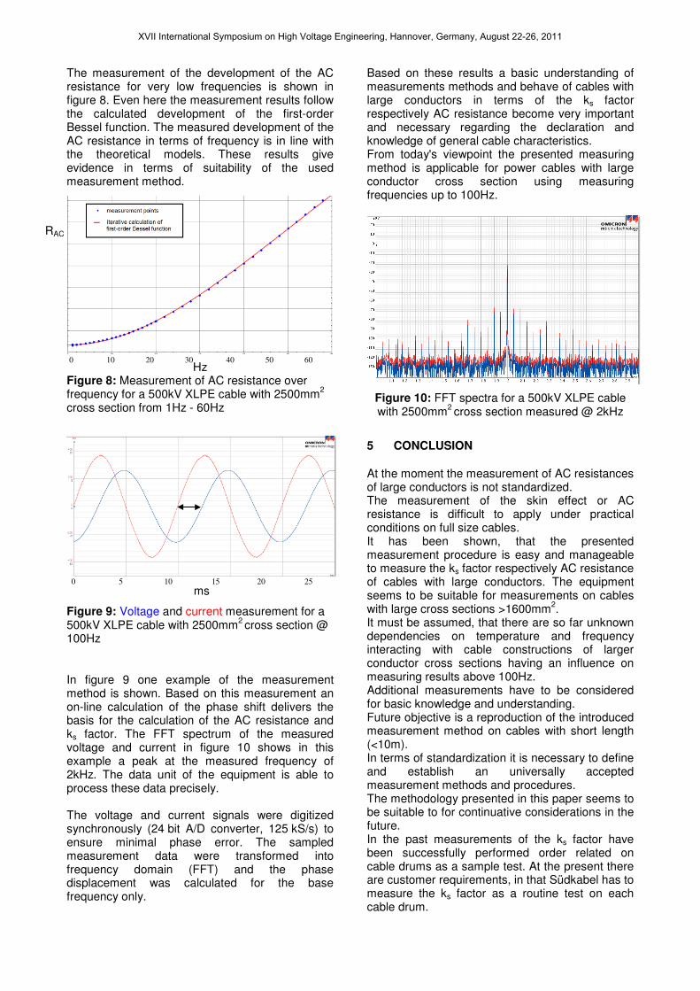
In figure 9 one example of the measurement method is shown. Based on this measurement an on-line calculation of the phase shift delivers the basis for the calculation of the AC resistance and ks factor. The FFT spectrum of the measured voltage and current in figure 10 shows in this example a peak at the measured frequency of 2kHz. The data unit of the equipment is able to process these data precisely. The voltage and current signals were digitized synchronously (24 bit A/D converter, 125 kS/s) to ensure minimal phase error. The sampled measurement data were transformed into frequency domain (FFT) and the phase displacement was calculated for the base frequency only.
Based on these results a basic understanding of measurements methods and behave of cables with large conductors in terms of the ks factor respectively AC resistance become very important and necessary regarding the declaration and knowledge of general cable characteristics. From today's viewpoint the presented measuring method is applicable for power cables with large conductor cross section using measuring frequencies up to 100Hz.
Figure 10: FFT spectra for a 500kV XLPE cable with 2500mm
2 cross section measured @ 2kHz
5 CONCLUSION
At the moment the measurement of AC resistances of large conductors is not standardized. The measurement of the skin effect or AC resistance is difficult to apply under practical conditions on full size cables. It has been shown, that the presented measurement procedure is easy and manageable to measure the ks factor respectively AC resistance of cables with large conductors. The equipment seems to be suitable for measurements on cables with large cross sections >1600mm
2.
It must be assumed, that there are so far unknown dependencies on temperature and frequency interacting with cable constructions of larger conductor cross sections having an influence on measuring results above 100Hz. Additional measurements have to be considered for basic knowledge and understanding. Future objective is a reproduction of the introduced measurement method on cables with short length (<10m). In terms of standardization it is necessary to define and establish an universally accepted measurement methods and procedures. The methodology presented in this paper seems to be suitable to for continuative considerations in the future. In the past measurements of the ks factor have been successfully performed order related on cable drums as a sample test. At the present there are customer requirements, in that Südkabel has to measure the ks factor as a routine test on each cable drum.
0 10 20 30 40 50 60
0 5 10 15 20 25
RAC
XVII International Symposium on High Voltage Engineering, Hannover, Germany, August 22-26, 2011

6 REFERENCES
[1] IEC 60287-1-1 Ed.1.2, "Electric cables – Calculation of the current rating – Part 1-1: Current rating equations (100 % load factor) and calculation of losses – General".
[2] IEC 60228 Ed.3, "Conductors of insulated cables".
[3] IEC 62067 Ed 2.0/ADIS © IEC, "Power cables with extruded insulation and their accessories for rated voltages above 150 kV (Um = 170 kV) up to 500 kV (Um = 550 kV) – Test methods and requirements".
[4] IEC 60840 Ed. 4.0/ADIS © IEC, "Power cables with extruded insulation and their accessories for rated voltages above 30 kV (Um = 36 kV) up to 150 kV (Um = 170 kV) – Test methods and requirements".
[5] E. H. Salter, "Problems in the Measurement of A-C Resistance and Reactance of Large Conductors". American Institute of Electrical Engineers, Transactions of the 67.2 (Jan. 1948), 1390–1397.
[6] E.H. Ball and G. Maschio. "The AC Resistance of Segmental Conductors as Used in Power Cables", Power Apparatus and Systems, IEEE Transactions on PAS-87.4 (Apr. 1968), 1143–1148.
[7] W. Kolbe. "Die Messung des Wechselstrom Verlustwiderstandes von Energiekabeln großen Querschnitts (Measurement of large crosssection cables AC resistance and assessment of losses) ", ETZ-A 95.7 (1974), 357– 359.
[8] F. Castelli, L. Maciotta-Rolandin and P. Riner. "A new method for measuring the A. C. resistance of large cable conductors", Power Apparatus and Systems, IEEE Transactions on 96.2 (Mar. 1977), 414 –422.
[9] K. Sugiyama u. a. "The skin effect of large size conductors for power cables", Conf. IEEJ Tokyo Branch. 6. Nov. 1977.
[10] C. Katz, G. S. Eager et. al., "Progress in the Determination of AC/DC Resistance Ratios of Pipe-Type Cable Systems", Power Apparatus and Systems, IEEE Transactions on PAS-97.6 (Nov. 1978), 2262–2271.
[11] K. Sugiyama. "Development of inter-layer insulated segmental conductor with low skin effect for power cables". Elect. Eng. Jpn. 101.6 (Nov. 1981), 98–108.
[12] D.A. Silver and G.W. Seman. "Investigation of AC/DC Resistance Ratios of Various Designs of Pipe-Type Cable Systems", Power Apparatus and Systems, IEEE Transactions on PAS-101.9 (Sep. 1982), 3481–3492.
[13] Kenji Matsuura et. al. "Development of calculation method for ac resistance of power cable conductors with individually insulated strands", Elect. Eng. Jpn. 103.5 (Sep. 1983), 47–56.
[14] M. Takaoka, S. Motai, M. Mochizuki and K. Watanabe, "Development of segmental conductors with cupricoxide film applied on strands", Fujikura Technical Review 14 (1985), 53–63.
[15] H. Brakelmann, "Belastbarkeiten von Energiekabeln Berechnungsmethoden und Parameteranalysen (Habilitationsschrift Universität Duisburg) ", VDE, 1985. ISBN: 3-8007- 1406-X.
[16] K. Ohata and T. Taneichi, "The application of new technologies on EHV XLPE cables", Power Delivery, IEEE Transactions on 5.2 (Apr. 1990), 753–759.
[17] J.L. Maksiejewski. "Losses in tubular cylindrical conductors due to current surges, taking skin effect into account", Science, Measurement and Technology, IEE Proceedings A 140.6 (Nov. 1993), 496–500.
[18] K. Ferkal, M. Poloujadoff and E. Dorison, "Proximty Effect and Eddy Current Losses in Insulated Cables",
IEEE Trans. Power Delivery 11.3 (1996), 1171–1178.
[19] George F. Anders, "Rating of Electric Power Cables. Ampacity Computations for Transmission", Distribution and Industrial Applications. IEEE Press, 1996. ISBN: 0-7803-1177-9.
[20] Dominik F.P. Joachim. "Stromverdrängungseffekte bei Millikenleitern". Diss. Universtität Duisburg, 1998.
[21] X. Bourgeat, J. Santana, A. Fustier and P.M. Dejean. "A new method for the measurement of power cables AC resistance", Proc. of Jicable’ 99. Bd. 2. Versailles, France, Jun. 1999, 561–565.
[22] P. Argaut and J.Y. Daurelle, "Calculation method of power cables AC resistance with individually insulated strands", Proc. of Jicable’ 99. Bd. 2. Versailles, France, Jun. 1999, 582–591.
[23] V.T. Morgan, R.D. Findlay and S. Derrah, "New formula to calculate the skin effect in isolated tubular conductors at low frequencies", Science, Measurement and Technology, IEE Proceedings - 147.4 (Jul. 2000), 169–171.
[24] Udo Fromm, "Optimized conductors for XLPE cables with a large cross-section", Euro. Trans. Electr. Power 15.2 (Mar. 2005), 109–121.
[25] E. Dorison, L. Moreau, U. Fromm, V. Barry, C. Remy, J.M. Mendez, A. Ueda, G. Barnewell and M. Shuvalov, "Large Cross-Sections and Composite Screen Design", Report 272. CIGRE Working Group B1-03. CIGRE, Jun. 2005.
[26] D. da Silva, G. Fernandez and R.A. Rivas, "Calculation of Frequency-Dependent Parameters of Pipe-Type Cables: Comparison of Methods", TDC. IEEE/PES Transmission Distribution Conference and Exposition: Latin America. Aug. 2006, 1–6.
[27] Hiroshi Suzuki and Mamoru Kanaoka. "Theoretical Investigation on Skin Effect Factor of Conductor in Power Cables", IEEJ Transactions on Power and Energy 126.8 (2006), 807–820.
[28] David Dubois and Pierre Mirebeau, "The Use of Insulated Wires Milliken Conductors in High Voltage Power Transmission Underground AC Lines", Proc. of Jicable’07. Versailles, France, Juni 2007.
[29] D. Douglass et. al., "Alternating current (ac) resistance of helically stranded conductors", Report 345. CIGRE Working Group B2-12. CIGRE, Apr. 2008.
[30] I. Manke, N. Kardjilov, M. Strobl, A. Hilger and J. Banhart, "Investigation of the skin effect in the bulk of electrical conductors with spin-polarized neutron radiography", Journal of Applied Physics 104 (2008).
ACKNOWLEDGEMENT The authors greatly appreciate the support of OMICRON mtronix Berlin by providing the high-accuracy vectorial measuring system.
GLOSSARY
XLPE Cross-Linked Polyethylene AC Alternating Current DC Direct Current FFT Fast Fourier Transformation f supply frequency in Hertz R´ DC. resistance per unit length
σσσσ conductor conductivity
µµµµ relative magnetic permeability
δδδδ eddy current losses ys skin effect factor xs argument of a Bessel function used to calculate skin effect ks factor used in calculating xs (skin effect)
XVII International Symposium on High Voltage Engineering, Hannover, Germany, August 22-26, 2011