large eddy simulation ofturbulent spray …cfdbib/repository/tr_cfd_05_31.pdf · large eddy...
TRANSCRIPT

LARGE EDDY SIMULATIONOFTURBULENT SPRAY COMBUSTIONINAERONAUTICAL GASTURBINESS. Pascaud1 , M. Boileau1 , B. Cuenot1 and T. Poinsot21 CERFACS, Toulouse, France2 IMFT, Toulouse, France
Abstract Reduction of pollutants emission or altitude re-ignition, strongly influenced byturbulent mixing and fuel spray evaporation, are critical issues for aeronauticalgas turbine design. To understand unsteady spray combustion in industrial burners,Large Eddy Simulation (LES) is a unique and powerful tool. Its potential has beenwidely demonstrated for turbulent gaseous cold and reacting flows. Its extensionto two-phase turbulent reacting flows is an obvious research path for the future. Inthe present work, an Euler-Euler formulation, together with a turbulent sub-gridscale model and a turbulent combustion model, is used to solve the conservationequations in each phase and the exchange source terms for mass, momentum andheat transfer. A stabilised turbulent spray flame in an aeronautical gas turbine isconsidered for application. Due to complex geometry, an unstructuredmesh is used.The partially premixed flame structure revealed by LES is detailed. In particular,the role of evaporation and recirculation zones on the stabilisation mechanism isemphasized. Finally, LES and RANS results are compared.
Keywords Large Eddy Simulation, spray, evaporation, combustion, complex geometry
CONTEXT
Large Eddy Simulations (LES) are rapidly becoming standard tools to studycombustion in many modern combustion devices [1-6]. However, even thoughmultiple proofs of the validity of the LES concept have been obtained forgaseous combustion, LES for two-phase flow combustion remains amuchmoredifficult topic for which very few recent studies are available [7-10]. Consid-ering that most fuels used for aeronautical applications are liquid, the needfor two-phase combustion LES tools is obvious. The turbulent spray combus-tion involves several different physical phenomena such as particle dispersion,vaporisation, mixing and combustion. The dispersion is highly linked to thecharacteristics of the spray. Experimental studies on dispersion of solid parti-cles [11] and vaporised droplets [12] have shown the influence of the Stokesnumber on the droplet trajectories. The isolated vaporising droplet model is asimple but useful description of the vaporising spray, required to understandthe physics [13-17]. Different approaches have been used to analyse vaporis-ing turbulent sprays : experiments [12, 18, 19], Direct Numerical Simulations(DNS) [20], LES [21] and Reynolds Averaged Navier Stokes (RANS) [18] or
turbulent spray combustion : experiments [22, 23], DNS [24-26], LES [27] andRANS [28, 29]. These recent studies exhibit the complexity of the multipleinteractions between turbulence, two-phase flows and combustion. The aim ofthis paper is to use LES to analyse these unsteady correlations.Modelling of the dispersed phase raises the question of the choice of the
method used to couple the liquid and the gas phases in a LES formulation. Inthe Lagrange approach, the liquid phase is computed using a particle trackingmethod in which each droplet (or group of droplets) is computed individu-ally giving its trajectory, velocity, temperature and diameter [7]. In the Eulerapproach, the liquid phase is homogeneized and solved for using a set of con-servation equations for the liquid volume fraction, the liquid phase velocity andtemperature, and the first/second order moments of the size distribution [30,31]. TheLagrange framework is used inmany applications because phenomenalike droplet break-up, dispersion, interaction with walls and droplet/droplet in-teraction are easier to model. This choice may be revisited for the computationof unsteady spray combustion in complex geometry. The first argument comesfrom the numerics : LES are high CPU consumers; run on parallel computers.However, a significant amount of work is still needed to implement efficientlyLagrange algorithms on parallel computers [10]. Moreover, the cost of theLagrange treatment increases rapidly with the number of droplets while theparallel efficiency decreases. On the other hand, Euler techniques are directlyparallelisedwith the same algorithms than the gas phase computations. Anothermajor issue for Lagrangian reacting two-phase LES is the number of dropletsper cell required to provide a correct description of the liquid phase. LES beingless dissipative than RANS, enough Lagrangian droplets must be used at eachtime step in each cell to provide a smooth and accurate continuous field offuel mass fraction. Because the fuel vapour distribution, directly produced bythe discrete droplet evaporation source terms, controls the propagation of thefront [32, 33], this is crucial for two-phase flame computations. Very limitedexperience on this question is available today but it is likely that combustionrequires much more particles than usually used for dispersion or evaporationstudies, leading to uncontrolled CPU costs. Another advantage of Lagrangemethods is that they naturally allow to track multisize droplet clouds. Size dis-tribution controls the flame regime in many instances and must be taken intoaccount. However, recent studies have demonstrated that Euler techniques mayalso be extended to include multisize liquid sprays [20, 34, 35]. Finally, a moregeneral question regarding LES of two-phase flow combustion is the difficultyof specifying inlet conditions for the liquid phase: close to the fuel injectors,the droplet velocity and size distributions are not known with precision dueto the complexity of primary atomization. The question then arises whetherit is worth computing the dispersion of the fuel droplets with a high-precision

Lagrange method while using very approximate injection conditions. Close tothe fuel injectors, the liquid phase is even not organized as droplets but moreas liquid blobs [36] showing that the Lagrange method cannot even be usedthere. In these high-loading zones where no real drop exists, using the Eulerapproach may actually be more compatible with the physics of the liquid phaseand the large uncertainties related to the fuel injection conditions.In this paper, the Euler framework is chosen for LES. The parallel solver
AVBP is described and the computation of a turbulent stable spray flame atatmospheric pressure in an industrial gas turbine sector is presented.
EQUATIONS
The Euler approach leads to similar conservation equations for both thecarrier phase and the dispersedphase, onwhichLESfiltering is then applied [37,38]. For the carrier phase, the classical LES set of equations is recovered. Itis coupled with the dispersed phase equations through phase exchange terms.The Favre averaged (defined as : φ = ρφ
ρ) governing equations for gas and
liquid mass and species conservation, momentum and total energy read :
DDt
(ρ) = Γ (1)
DDt
(ρYk) =∂
∂x j(ρDk
∂Yk
∂x j)− ∂
∂x j(ρYsgs)+ ¯ωk + ΓδkF (2)
DDt
(ρui) = − ∂
∂xip+
∂
∂x jτi j −
∂
∂x j(ρusgs)+ Ii (3)
DDt
(ρE) = − ∂
∂x jq j +
∂
∂x j(τi j ui)−
∂
∂x j(ρEsgs)+ ¯ωT + Ii ui + Π (4)
DDt
(αl ρl ) = −Γ (5)
DDt
(αl ρl ui,l ) = −Ii (6)
DDt
(αl ρl hs,l ) = −Π (7)
DDt
(n) = 0 (8)
In these equations, ρ (ρl ) is the gas (liquid) mass density, Yk is the massfraction of the species k and ui (ui,l ) is the gas (liquid) velocity. E is the total
non chemical energy of the carrier phase defined as : E = es+ 12uiui where es
is the sensible energy and hs,l is the liquid sensible enthalpy. Finally, αl is thevolumic liquid fraction and n is the droplet density.The stress tensor τi j is assumed newtonian and the heat diffusion q j is
determined by the Fourier law. The unresolved turbulent fluxes Ysgs= u jYk−Vc
k, jYk and Esgs= u jE− u j E are estimated by a classical gradient diffusionassumption. The subgrid stresses usgs = uiu j − ui u j are modeled with theWALE formulation [39].The mass transfer Γ is expressed by the Spalding model [40] for spherical
droplets :
Γ = αl6d2Sh(ρDΓ)ln(1+BM) (9)
where the Sherwood Number Shis equal to 2 and the Spalding number is de-fined by : BM = (YF,ζ −YF)/(1−YF,ζ ) with ζ denoting the value at interface.The momentum transfer is defined as Ii = Fd,i +ui,l Γ where Fd,i is the stan-
dard drag force of a spherical droplet equal to−αl3Cd4d ρg|ui,l −ui,g|(ui,l −ui,g).
The drag coefficientCd is, for Red ≥ 1000, taken constant at 0.44and equal to24
Red(1+0.15Re0.687
d ) otherwise, with the droplet Reynolds number defined asRed = d
νg|ui,l −ui,g|.
The enthalpy exchange is :
Π = Λ+Φ (10)
where Λ is the contribution of mass transfer and Φ is the heat flux throughthe interface. The enthalpy transfer linked to evaporation is taken as Λ =hF,ζ Γ where hF,ζ is the sensible enthalpy of vaporised fuel. The heat flux isdefined by Φ = αl λNu 6
d2 (Tζ −T) where Nu is the Nusselt number and Tζ isthe temperature at the interface.The reaction rate ωk and the heat release ωT are modeled by an Arrhenius
law [41] with coefficients fitted by a genetic algorithm [42] from a reducedchemistry [43] to the present one-step chemistry : JP10+14O2 ⇀↽ 10CO2 +8 H2O using criteria such as flame speed and thickness. The fuel JP10 isa substitute for kerosene and has the same thermochemical properties. Theflame/turbulence interaction is modeled by the thickened flame model [6].
THE LES CODE
The LES solver AVBP is a finite volume code, computing the equations forboth phases with the same numerical method on the same unstructured mesh.It is explicit in time and takes into account the variations of molecular weights

and heat capacities with temperature and mixture composition. Boundary con-ditions used for inlets and outlet are non-reflective NSCBC conditions withrelaxation coefficients [44]. Symmetry conditions are used on the burner sides,while non-slip adiabatic walls are used elsewhere. The unstructured mesh iscomposed of 2.3million of tetrahedral elements. In this application, the timestep is about ∆t = 0.2µs. To calculate one turnover time of the swirled flowτswirl ' 3.5ms, the LES computation of the turbulent spray flame takes one dayon SGI ORIGIN 3800 on 64 processors.
CONFIGURATION
The configuration is a 1/16th part of an annular combustion chamber. Thegeometry takes into account themain swirled inlet, the primary jets, the dilutionjets and the cooling films that preserve the lower and upperwalls from the flame.A sketch of the geometry and a view of the mesh are presented on Figure 1. Thefour primary jets are located on upper and lower walls, between the centeredvertical plane and the sides of the burner, leading to highly turbulent impacts.Ten dilution jets are placed downstream to create a "cold wall" composed ofcooling air, limiting the outlet temperature to preserve the downward turbinestructure.
a.
X
Y
Z
b.
Figure 1: a. Geometry of the configuration, b. Mesh view (central plane)
INLET CONDITIONS
Air at 525 K is injected by two annular swirlers located upstream of thecomputational domain. The inner swirler is located between r∗ = r/rmax= 0and 0.4, where rmax is the maximum radius of the outer swirler and r∗ isdefined as illustrated on Figure 2a. Using a cylindrical referential, the velocitycomponents of the main swirled inlet (Figure 2b) are normalised by the bulkvelocityUbulk and noted with the symbol ∗. The normal and radial components

u∗n and u∗r are strongly influenced by both swirlers : their value is higher aroundthe external radius of each swirler. The Reynolds number based on the bulkvelocityUbulk and the maximum injection radius rmax is equal to Re= 15000.The liquid fuel cone is defined by specifying αl ' 10−3 in the inner zoneand zero elsewhere, and taking the liquid velocity equal to the inlet gaseousvelocity. The initial diameter of the kerosene droplets is 15µm, and theirtemperature is 288K. The Stokes number, based on the droplet relaxation timeτp = ρl d
2
18µ= 2.0 ms, is equal to St= τp
τswirl' 0.6. This means that the droplet
trajectories are quite correlated to the carrier phase motion. This correlationrises when the diameter of the vaporising droplets decreases.
a. b.
3.0
2.5
2.0
1.5
1.0
0.5
0.0
-0.5
u*
1.00.80.60.40.20.0
r*
inner zone
Figure 2: a. Definition of r*, b. Radial profiles of u∗n ( ), u∗r ( ◦ ) and u∗θ( )
LES RESULTS
Dynamics
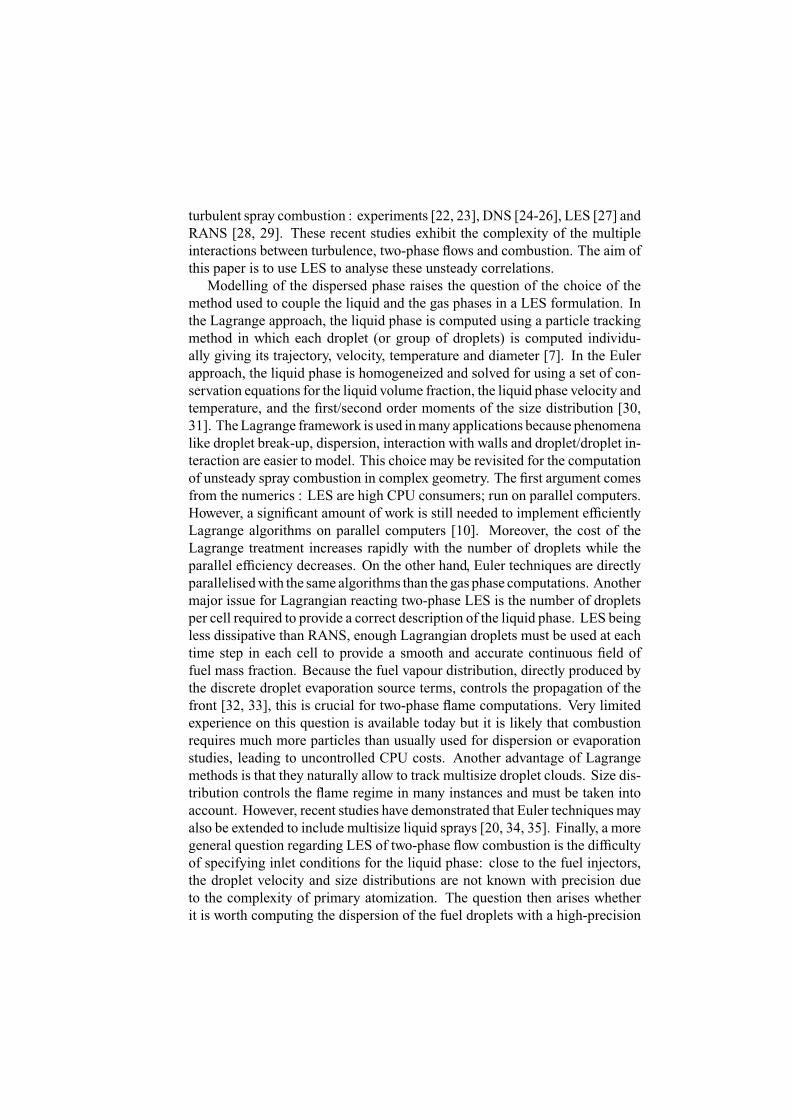
The swirled inlet generates a precessing motion and a recirculation zone,starting close to the fuel injection and stopped by the primary jets. The transver-sal half length of the recirculation zone is r∗ ' 0.4−0.6. An instantaneousview of the dynamics on the vertical central plane is presented on Figure 3a.The location of the primary jets, the dilution jets and the fuel injection is in-dicated. The solid line shows the zone where the axial velocity is opposite tothe main flow direction. The impact of the primary jets on each other stronglyinfluences the dynamics as illustrated on Figure 3b, where the y-component ofthe velocity is plotted on the plane of the primary jets.
a.
rdump
primary jets
fuel
dilution jets
u = 0 m.s-1 b. -100
0
100
v
u = -5 m.s-1
Figure 3: a. Back flow line, b. Primary jets : y-velocity field
PrecessingVortex Core
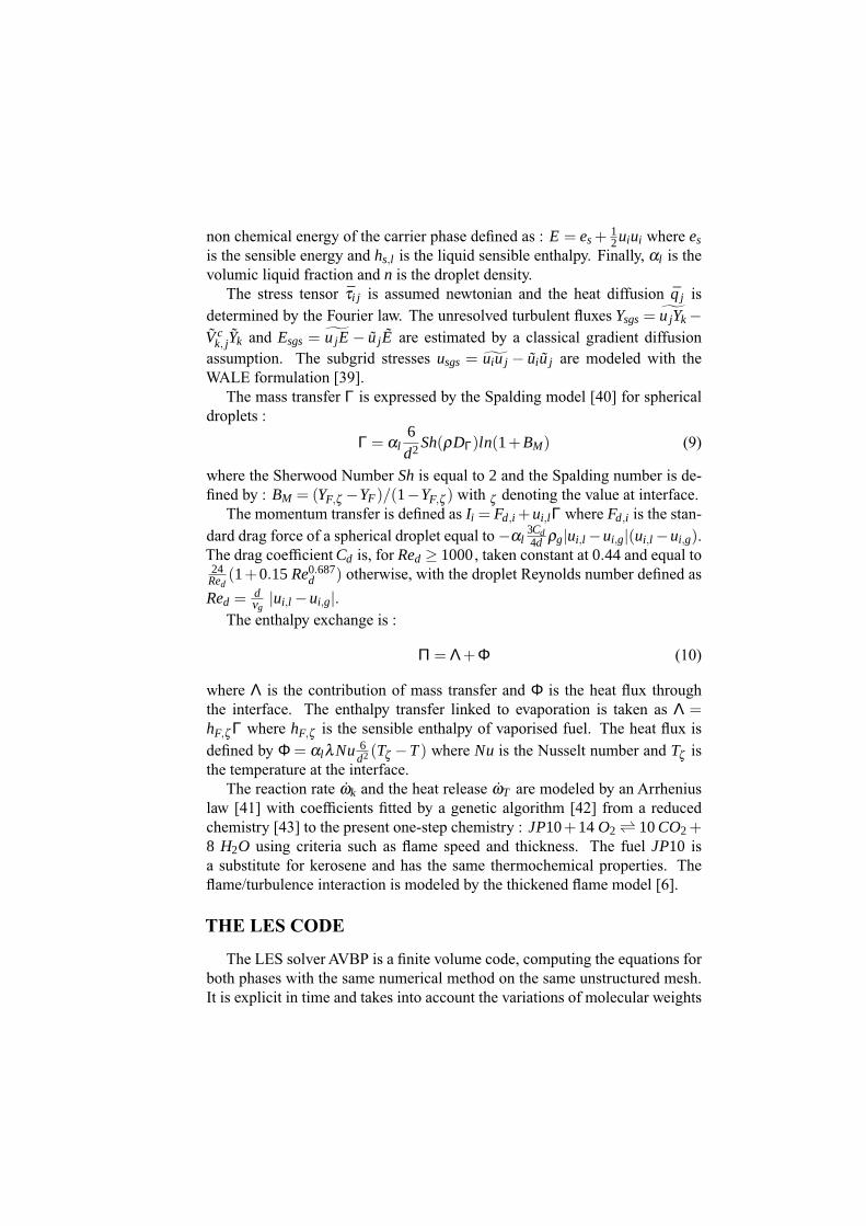
In its review on vortex breakdown [44], Lucca-Negro classifies the differenttopologies of swirling flows using the swirl number. One of these topologiesat high swirl number is the precessing vortex core (PVC) : due to the swirl,the axial vortex breaks down at the stagnation point S and a spiral is createdaround a recirculation zone as illustrated on Figure 4a. In this application, theswirl number (based on rdumpdefined on Figure 3a) is equal to :
S=1
rdump
rdump∫0
uwr2dr
rdump∫0
u2r dr
= 0.44 (11)
Using the transverse planeA-Bdefined onFigure 5a, the backflow line is plottedon Figure 4b at six successive times marked with a number from 1 to 6 andseparated by 0.5 ms. The precessing motion is then illustrated in the presentconfiguration with a turnover time equal to τswirl ' 3.5ms, corresponding to afrequency of fPVC' 286Hz.
a.
S
b.
Figure 4: a. Sketch of the PVC ; b. Backflow line at six successive times
Dispersion
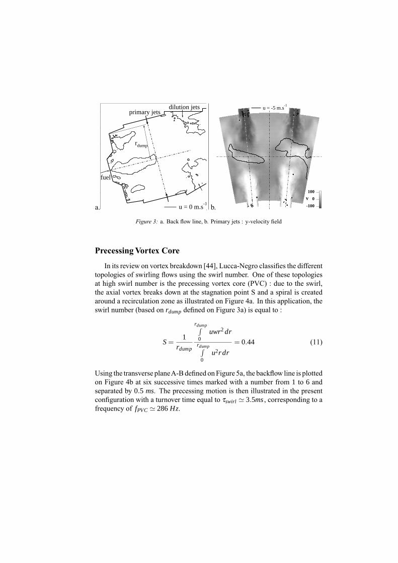
Due to their relatively low Stokes number, the droplets motion is controlledby the carrier phase so that the recirculation zone of the carrier phase and of thedispersed phase are similar. This can be observed on Figure 5a, where the u= 0isolines of both phases are superposed. Since the droplets are constrained bythe recirculation zone, they accumulate in a region close to the injector wherethe droplet density and the volumic fraction increase above the injection value.Radial dispersion by the swirl is also visible on Figure 5b.
a.
u = 0 m.s-1
ul = 0 m.s-1
n = 1.1 ninj
cut plane
1.6x10⁻³
1.2
0.8
0.4
0.0
αl
A
B
b.
u = 0 m.s-1
ul= 0 m.s-1
n = 1.1 ninj
A
B
Figure 5: a. accumulation ; b. radial dispersion

Evaporation
Evaporation can be characterised on Figure 6 by the mass and heat transferfluxes Γ and Π (see Equation 9 and Equation 10). The evaporation zone islocated where fuel vapour is created. To describe the resulting fuel vapourdistribution, the mixture fraction and local equivalence ratio are respectivelydefined by :
Z =sYJP10−YO2 +YO2,0
sYJP10,0 +YO2,0
(12)
φ =Z
1−Z1−Zst
Zst(13)
with YO2,0 = 0.233, YJP10,0 = 1 and Zst = 0.066. In the evaporation zone, themass transfer is high and leads to high variations of the local equivalence ratio.This zone is globally very rich as illustrated by the field of equivalence ratioon Figure 6a. The heat conduction Φ controlled by the temperature differenceis relative and heats the droplets (reducing the air temperature as illustrated onFigure 6b) while the enthalpy transfer Λ linked to the mass transfer is positive.The global heat transfer Π takes positive values where the heat released by theflame front accelerates the evaporation.
a.
1050
φ
Γ = 10 kg.m3.s-1
Z = Zst
b.
-200
-160
-120
-80
-40
0
Π (.106 kg.m3.s-1)
T = 400 K
Figure 6: a. Equivalence ratio φ and mass transfer Γ , b. Heat transfer Π
Flame structure
The chemical reaction takes place where fuel vapour, oxidant and hot gasesare simultaneously present. The evaporation zone brings fuel vapour and the

recirculation zone brings hot gases : the flame front, presented on Figure 7a,is attached to the evaporation zone and stabilised by the recirculation zone. Itis actually composed of two successive fronts separated by the primary jets.In order to distinguish premixed and diffusion flame fronts, theTakeno index
T = ∇YF .∇YO and an indexed reaction rate ω∗F = ωF
T|∇YF |.|∇YO|
are used. Theflame structure is then divided in two parts : ω∗
F = +ωF in premixed regimeand ω∗
F =−ωF in diffusion regime. Results are shown on Figure 7b. Close tothe dispersion and evaporation zones, the turbulent mixing between reactantscreate a rich partially premixed spray flame limited by the primary jets. Bycontinously creating pure fuel vapour, the evaporation process reinforces thepartially premixed regime. An important point is that the reaction rate is verylow there. The unburned fuel vapour and the cold air of the dilution jets thencreate a second flame front in the diffusion regime. This is clear through theTakeno index but also through the superposition of the reaction rate and thestoichiometric line.
a. -40-30-20-100
Z = Zst
ωF
b.
diffusionpremixed Z = Zst
Figure 7: a. Reaction rate ωF , b. Indexed reaction rate ω∗F
Stabilisation mechanism
Classical combustion models of twin-fluid atomized jet spray [45, 46] areused to characterise the main competitive phenomena for flame stabilisation :
1. the air velocitymust be low enough tomatch the turbulent flamevelocity :the dynamics of the carrier phase (and in particular themain recirculationzone) stabilise the flame front on a stable pocket of hot gases
2. zones where the local mixture fraction is within flammability limits mustexist : combustion occurs between the fuel vapour radially dispersed by

the swirl and the ambient air, where the equivalence ratio is low enough3. the heat release must be high enough to maintain evaporation and reac-tion : the sum of heat flux Π and heat release ωT , plotted on Figure 8a.,allows to identify the zone ( )where the heat transfer due to evaporationextinguishes the flame : Π+ ωT = 0.
In the present case, the flame stabilisation is the result ofmechanisms 1. and 3. :the flame starts in the recirculation zonewhere residence times are high enough,and is maintained at a certain distance by the cooling effect of evaporation. Themechanism 2. is not preponderant because the flow is within the flammabilitylimit for a large range of the local mixture fraction, as illustrated by the mixturefraction diagram of reaction rate presented on Figure 8b.
a.
4x10⁹
2
0
Π + ωT
b.
Figure 8: a. Sum of heat fluxes Π+ ωT ; b. Reaction rate
PVC influence
The PVC generated by the swirl influences the dynamics of both the evapo-ration and combustion zones. The precessing unsteady evolution of fuel massfraction (white solid line), heat release (black solid line) and temperature fieldis presented on Figure 9, on the transverse planeA-B defined on Figure 5a. Therecirculation zones stabilise hot gases at the center of the combustion chamberand near the lateral sides. Between these hot regions, a cold annular zone corre-sponds to the evaporation domain. The fuel mass fraction isolines (YJP10 > 0.2)are located in this zone and precess around the central recirculation zone. Theflame motion is controlled by two main mechanisms : the central recirculationzone stabilises directly the flame front and evaporation brings fuel vapour to theflame. Therefore, the flame front also precesses around the central recirculationzone and is attached to the evaporation zone.

a.⇒b.
Time between each successive image : 0.5 ms ⇓
d.⇐c.
Figure 9: a.→d. Temperature field, fuel mass fraction (white solid line) and heat release (blacksolid line) at four successives times
AVERAGED FIELDS
Mixture fraction
Scatter plots of mean temperature Tg and oxygen mass fraction YO2 versusthe mixture fraction are presented on Figure 10. Theoretical lines represent-ing pure mixing ( ) and infinitely fast chemistry ( ) are also shown.Compared to gaseous combustion, the evaporation process implies main dif-ferences on the flame structure. First, the maximum mixture fraction does notexceed Zmax= 0.65 (with the reference fuel mass fraction fixed at YJP10,0 = 1in Equation 12). This corresponds to the maximum fuel mass fraction at thelimit of saturation of the liquid fuel which is equal to YJP10,ζ = 0.65. Sec-ond, in the evaporation zone, the gaseous temperature goes below the injection

temperature and therefore, below the mixing line. Third, for mixture fractionshigher than the stoichiometric value (evaporation zone), the effects of mixingare stronger than the effects of chemistry because the high heat and mass trans-fers decrease the gaseous temperature and increase the local equivalence ratio.The structure of the obtained scatter plots can be analysed as in Réveillon andal.[25] studying the differences between gaseous and two-phase flames using aDNS approach. In particular, as presented on Figure 11, the intermediate linescorresponding to two-phase reaction can be identified.
a. b.
Figure 10: LES Mixture fraction diagrams
a. b.
Figure 11: DNS Mixture fraction diagrams [25]
LES vs. RANS
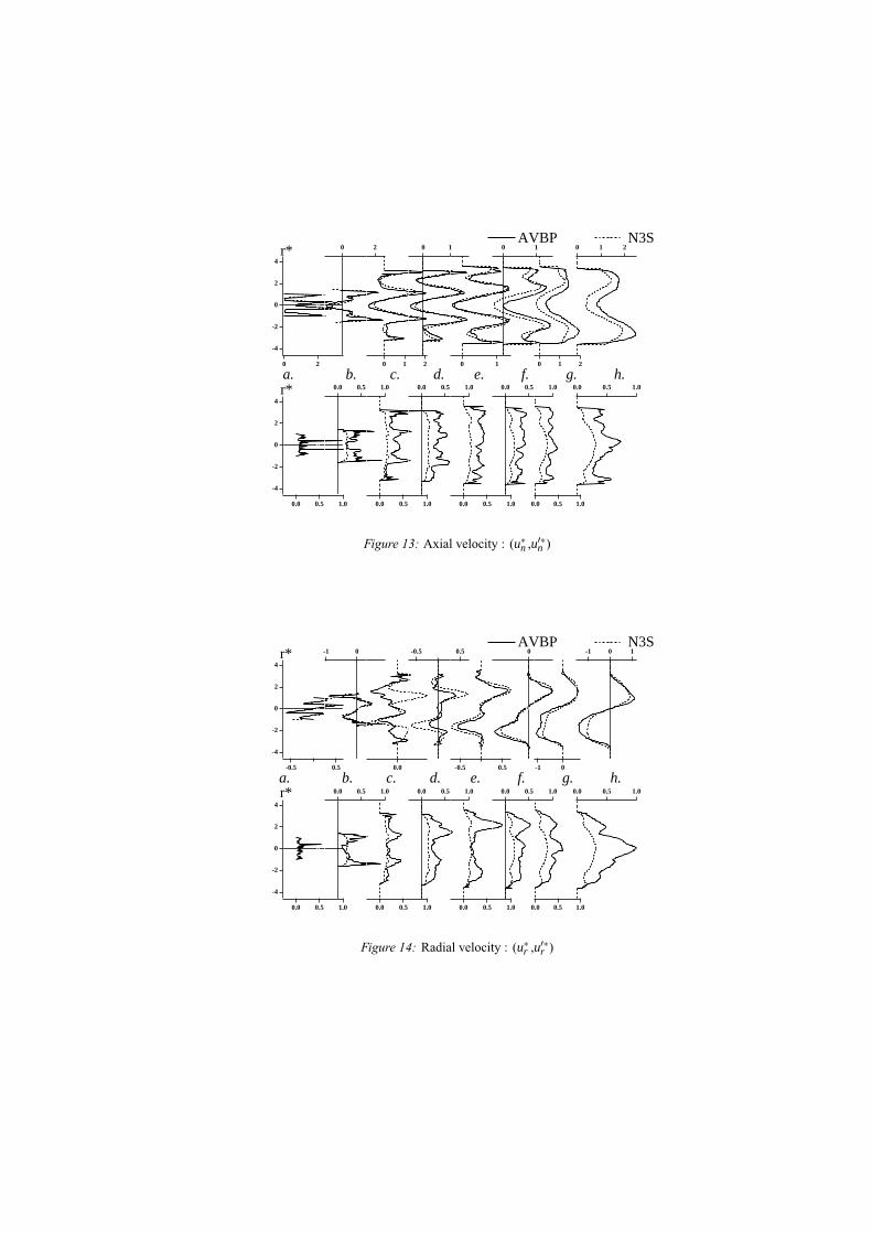
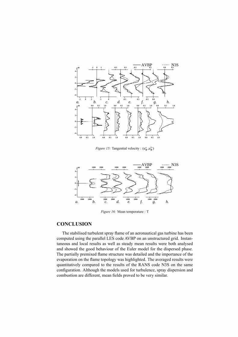
For comparison, the same configuration has been run on the same meshwith the RANS code N3S using the models summarised in Table 1. Mean andfluctuating normalised velocities are compared on the vertical central plane atdifferent cutting lines presented on Figure 12. The axial, radial and tangentialcomponents are respectively presented on Figure 13, Figure 14 and Figure 15.The main flow is strongly influenced by the jets penetration. The agreement
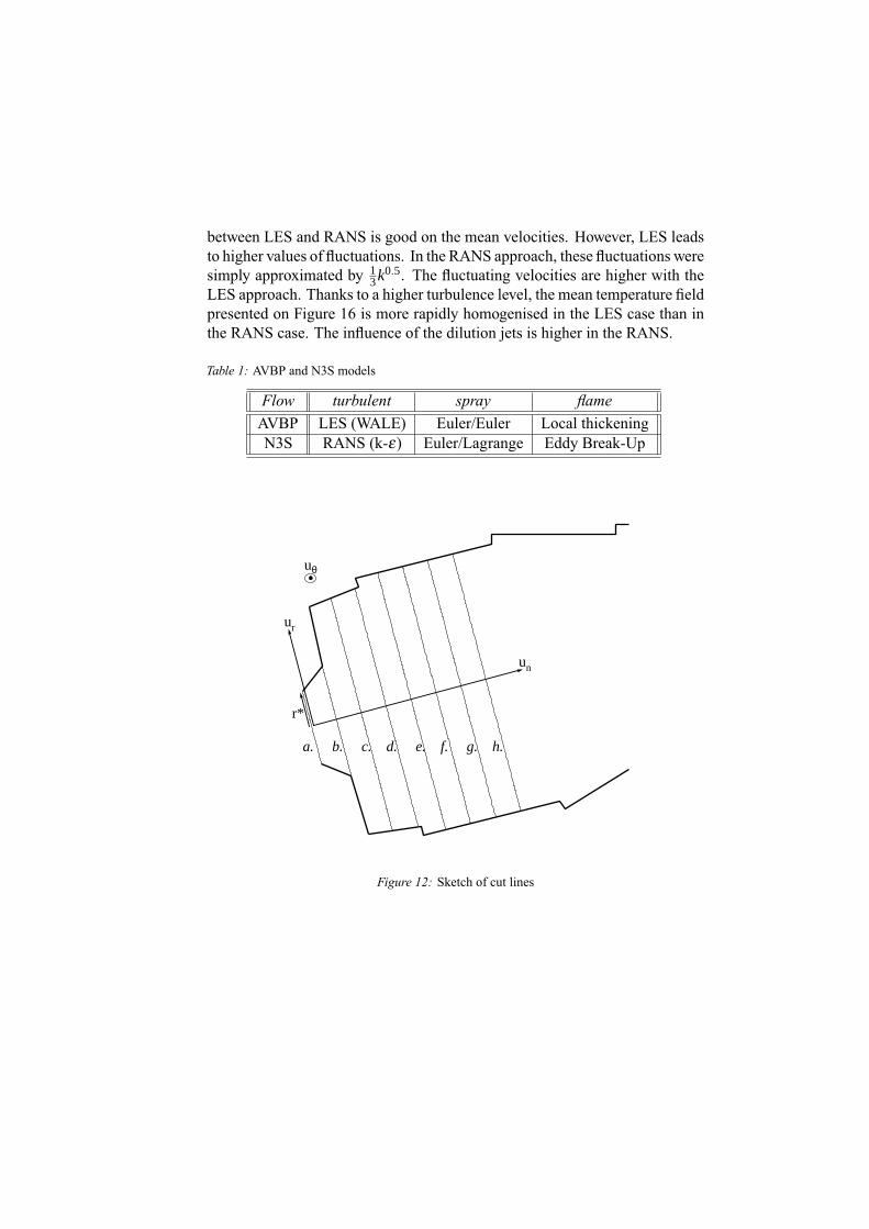
between LES and RANS is good on the mean velocities. However, LES leadsto higher values of fluctuations. In the RANS approach, these fluctuations weresimply approximated by 1
3k0.5. The fluctuating velocities are higher with theLES approach. Thanks to a higher turbulence level, the mean temperature fieldpresented on Figure 16 is more rapidly homogenised in the LES case than inthe RANS case. The influence of the dilution jets is higher in the RANS.
Table 1: AVBP and N3S models
Flow turbulent spray flameAVBP LES (WALE) Euler/Euler Local thickeningN3S RANS (k-ε) Euler/Lagrange Eddy Break-Up
Y [
mm
]
X [mm]
r*
un
uθ
ur
a. b. c. d. e. f. g. h.
Figure 12: Sketch of cut lines
-4
-2
0
2
4
20
0
20
0
210
0
10
0
10
0
10
0
210
0
210
-4
-2
0
2
4
1.00.50.0
0
1.00.50.0
0
1.00.50.0
0
1.00.50.0
0
1.00.50.0
0
1.00.50.0
0
1.00.50.0
0
1.00.50.0
AVBP N3Sr*
r* a. b. c. d. e. f. g. h.
Figure 13: Axial velocity : (u∗n ,u′∗n )
-4
-2
0
2
4
0.5-0.5
0
-1 0
0
0.0
0
-0.5 0.5
0
0.5-0.5
0
0
0
-1 0
0
-1 0 1
-4
-2
0
2
4
1.00.50.0
0
1.00.50.0
0
1.00.50.0
0
1.00.50.0
0
1.00.50.0
0
1.00.50.0
0
1.00.50.0
0
1.00.50.0
AVBP N3Sr*
r* a. b. c. d. e. f. g. h.
Figure 14: Radial velocity : (u∗r ,u′∗r )
-4
-2
0
2
4
20-2
0
10-1
0
-1 0
0
0.5-0.5
0
0.5-0.5
0
-0.5 0.5
0
0.0-0.5
0
0.0 0.5
-4
-2
0
2
4
1.00.50.0
0
1.00.50.0
0
1.00.50.0
0
1.00.50.0
0
1.00.50.0
0
1.00.50.0
0
1.00.50.0
0
1.00.50.0
AVBP N3Sr*
r* a. b. c. d. e. f. g. h.
Figure 15: Tangential velocity : (u∗θ,u′∗
θ)
-4
-2
0
2
4
20001000
0
20001000
0
20001000
0
20001000
0
20001000
0
20001000
0
20001000
0
20001000AVBP N3S
r*
a. b. c. d. e. f. g. h.
Figure 16: Mean temperature : T
CONCLUSION
The stabilised turbulent spray flame of an aeronautical gas turbine has beencomputed using the parallel LES code AVBP on an unstructured grid. Instan-taneous and local results as well as steady mean results were both analysedand showed the good behaviour of the Euler model for the dispersed phase.The partially premixed flame structure was detailed and the importance of theevaporation on the flame topology was highlighted. The averaged results werequantitatively compared to the results of the RANS code N3S on the sameconfiguration. Although the models used for turbulence, spray dispersion andcombustion are different, mean fields proved to be very similar.

The LES approach brings here a totally new insight into the physics of suchreactive two-phase flows, particularly on the unsteady mechanisms of a turbu-lent spray flame involving hydrodynamics ( like the main swirled inlet and thetransversal jets), particles dispersion and their evaporation, and combustion.The high variations of the local equivalence ratio in the evaporation zone andthe stabilisation mechanism, controlled by both dynamics and evaporation arecritical phenomena for such systems that deserve detailed and accurate studies.As a conclusion, this LES approach is a promising tool to investigate complexunsteady problems such as ignition, pollutant formation or response of a sprayflame to complex acoustic perturbation.
REFERENCES1. Desjardins P. E. and Frankel S. H. Two dimensional Large Eddy Simulation of sootformation in the near field of a strongly radiating nonpremixed acetylene-air jet flame.Combust. Flame; 119: 121-133, 1999.
2. Colin O., Ducros F., Veynante D. and Poinsot T. A thickened flame model for large eddysimulations of turbulent premixed combustion. Phys. Fluids; 12: 1843-1863, 2000.
3. Angelberger C., Egolfopoulos F. and Veynante D. Large Eddy Simulations of chemicaland acoustic effects on combustion instabilities.FlowTurb. andCombustion; 65: 205-22,2000.
4. Pitsch H. and Duchamp de la Geneste L. Large Eddy Simulation of Premixed TurbulentCombustion using a level-set approach.Proceedings of the Combustion Institute; 29: inpress, 2002.
5. Pierce C. D. and Moin P. Progress-variable approach for large eddy simulation of non-premixed turbulent combustion. J. Fluid Mech.; 504: 73-97, 2004.
6. Selle L., Lartigue G., PoinsotT., Koch R., Schildmacher K.-U., KrebsW., Prade B., Kauf-mann P. andVeynante D. Compressible Large-Eddy Simulation of turbulent combustionin complex geometry on unstructured meshes. Combust. Flame; 137: 489-505, 2004.
7. Mahesh K., Constantinescu G., Apte S., Iaccarino G., Ham F. and Moin P. Progresstowards Large-eddy simulation of turbulent reacting and non-reacting flows in complexgeometries. Annual Research Briefs; 115-142, 2002.
8. Mahesh K., Constantinescu G. and Moin P. A numerical method for Large-eddy simula-tion in complex geometries. J. Comput. Phys.; 197: 215-240, 2004.
9. Apte S. V., Gorokhovski M. and Moin P. Large-eddy simulation of atomizing spray withstochastic modeling of secondary breakup. ASME Turbo Expo 2003 - Power for Land,Sea and Air; 2003, Atlanta, Georgia, USA;
10. Ham F., Apte S. V., Iaccarino G., Wu X., Herrmann M., Constantinescu G., MaheshK. and Moin P. Unstructured LES of reacting multiphase flows in realistic gas turbinecombustors. Annual Research Briefs - Center for Turbulence Research; 2003.
11. SommerfeldM. andQiuH.H.Detailedmeasurements in a swirling particulate two-phaseflow by a phase-Doppler anemometer.Int. J. Heat and Fluids Flows; 12: 1991.
12. Sommerfeld M. and Qiu H. H. Experimental studies of spray evaporation in turbulentflow.Int. J. Heat and Fluids Flows; 19: 10-22, 1997.
13. GradingerT. B. andBoulouchosK.A zero-dimensionalmodel for spray droplet vaporiza-tion at high pressures and temperatures.International Journal of Heat and Mass transfer;2947-2959, 1998.
14. Miller R. S., Harstad K. and Bellan J. Evaluation of equilibrium and non-equilibriumevaporationmodels formany-droplet gas-liquidflowsimulations.Int. J.MultiphaseFlow;1025-1055, 1998.
15. Catoire F., Gauthier J. E. D., Bardon M. F. and BenaissaA. Quasi-Steady-State Evapora-tion Model for Real Multi-component Fuel Droplets.Journal of the Institute of Energy;134-142, 1999.
16. Réveillon J. and Vervisch L. Spray vaporization in nonpremixed turbulent combustionmodeling : a single droplet model. Combust. Flame; 75-90, 2000.
17. Burger M., Schmehl R., Prommersberger P., Schaefer O., Koch R. and Wittig S. Amulti-component droplet evaporation model for real aviation fuels at elevated pressures.ILASS-Europe; 2002, Zaragoza;
18. Gemci T., Hom J. and Chigier N. Simulation of evaporating spray and comparison withdroplet temperature measurement obtained by rainbow refractometer. ASME FluidsEngineering Division; 2000,
19. Brandt M., Gugel K. O. and Hassa C. Experimental investigation of the liquid fuelevaporation in a premix duct for lean premixed and prevaporized combustion.J. of Eng.for Gas Turb. and Power; 119: 815-821, 1997.
20. Réveillon J.,MassotM. andPeraC.Analysis andmodeling of the dispersion of vaporizingpolydispersed sprays in turbulent flows. Proceedings of the Summer Program 2002 -Center for Turbulence Research; 2002,
21. Caraeni D., Bergström C. and Fuchs L. Modeling of liquid fuel injection, evaporationand mixing in a gas turbine burner using Large Eddy Simulations.Flow Turb. and Com-bustion; 223-244, 2000.
22. Presser C., Gupta A. K. and Semerjian H. G. Aerodynamic characteristics of swirlingspray flames : pressure-jet atomizer. Combust. Flame; 25-44, 1993.
23. Sornek R. J., Dobashi R. and HiranoT. Effect of turbulence on vaporization, mixing, andcombustion of liquid-fuel sprays. Combust. Flame; 120-479, 2000.
24. SirignanoW.A.Theoretical Foundations for theAnalysis of Laminar andTurbulent SprayFlows. Proceedings of the Western States Section/Combustion Institute Fall Meeting;2003,
25. Réveillon J. andVervisch L.Analysis of weakly turbulent diluted-spray flames and spraycombustion diagram.Under consideration for publication in J. Fluid Mech.; 2004.
26. Vervisch L., Hauguel R., Domingo P. and Rullaud M. Three facets of turbulent combus-tion modelling: DNS of premixedV-flame, LES of lifted nonpremixed flame and RANSof jet flame.J. of Turb.; 5: 004, 2004.
27. SankaranV. and Menon S. LES of spray combustion in swirling flows.J. of Turb.; 3: 011,2002.
28. Klose G., Schmehl R., Meier R., Meier G., Koch R., Wittig S., Hettel M., LeuckelW. and Zarzalis N. Evaluation of advanced two-phase flow and combustion models forpredicting low emission combustors. ASMETurbo Expo 2000. 45thASMEGasTurbineand Aeroengine Congress; 2000, Munich;
29. GuoY. C., Chan C. K. and Lau K. S. A pure Eulerian model for simulating dilute spraycombustion.Fuel; 2131-2144, 2002.
30. Pandya R. and Mashayek F. Two-fluid large-eddy simulation approach for particle-ladenturbulent flows.Int. J. Heat and Mass Transfer; 45: 4753-4759, 2002.

31. Riber E., Moreau M., Simonin O. and Cuenot B. Towards Large Eddy Simulation ofNon-Homogeneous Particle Laden Turbulent Gas Flows Using Euler-Euler Approach.11th Workshop on Two-Phase Flow Predictions; 2005, Merseburg, Germany;
32. Pitsch H. and Peters N. A consistent flamelet formulation for non-premixed combustionconsidering differential diffusion effects. Combust. Flame; 114: 26-40, 1998.
33. Selle L., Lartigue G., Poinsot T., Kaufman P., Krebs W. and Veynante D. Large EddySimulation of turbulent combustion for gas turbineswith reduced chemistry. Proceedingsof the Summer Program - Center for Turbulence Research; 2002, 333-344
34. Borghi R. Background on droplets and sprays. Combustion and turbulence in two phaseflows, Lecture Series 1996-02; 1996,
35. Delabroy O., Lacas F., Labegorre B. and Samaniego J.-M. Paramètres de similitude pourla combustion diphasique.Rev. Gén. Therm.; 934-953, 1998.
36. Reitz R. D. and Diwakar R. Structure of high pressure fuel sprays. Tech. Rep. 870598.SAE Technical Paper. 1987
37. Simonin O. Continuum modelling of dispersed two-phase flows. Combustion and tur-bulence in two phase flows, VKI Lecture Series 1996-02; 1996, Von Karman Institutefor Fluid Dynamics;
38. Février P., Simonin O. and Squires K. Partitioning of particle velocities in gas-solidturbulent flows into a continuous field and a spatially-uncorrelated random distribution: theoretical formalism and numerical study.submitted to J. of Fluid Mech.; 2005.
39. NicoudF. andDucros F. Subgrid-scale stressmodelling based on the square of the velocitygradient.Flow Turb. and Combustion; 62: 183-200, 1999.
40. Spalding D. B. The combustion of liquid fuels. 4th Symposium (Int.) on Combustion;1953, Combustion Institute, Baltimore, MD; 847-864
41. Poinsot T. and Veynante D. Theoretical and numerical combustion, 2001.42. Martin C. EPORCK User Guide V1.8. 200443. Li S. C., Varatharajan B. and Williams F. A. The chemistry of JP-10 ignition.AIAA; 39:
2351-2356, 2001.44. PoinsotT. andLele S. Boundary conditions for direct simulations of compressible viscous
flows. J. Comput. Phys.; 101: 104-129, 1992.45. Gupta A. K., Lilley D. G. and Syred N. Swirl flows, 1984.46. Chigier N. A. Application of model results to design of industrial flames. Proc. of 4th
symposium of flames and industry; 1972, IC, London;
ACKNOWLEDGEMENTS
Most of the computations have been performed on the supercomputers ofCINES. Snecma Moteurs is gratefully acknowledged for its support.