large platform scissor alignment lift 5€¦ · -with guide rail for rolling jack, ... scissor lift...
TRANSCRIPT

USER’S MANUAL
LARGE PLATFORM SCISSOR ALIGNMENT LIFT
5.5M4
User’s Manual
Operation Manual & Instruction

USER’S MANUAL
I
MANUFACTURER AND SERVICE AGENT
HYDRAULIC AUTOMOBILE LIFT
MODEL:
Serial No.:
Year of manufacture:
Manufacturer:
Name:Address:
Tel:
Fax:
E-mail:
AUTHORISED SERVICE CENTRE:
USER’S MANUAL
II
Contents
Contents
Manufacturer and service
Packing, transport and storage
Introduction
Description of the machine
Technical specifications
Safety
Installation
Adjustment
Operation
Maintenance and care
Troubleshooting
Accessory

USER’S MANUAL
1
PACKING, TRANSPORT AND STORAGE
Packing dimension picture:
Transport:
Packing can be lifted or moved by lift trucks, cranes or bridge cranes.
In case of slinging, a second person must always take care of the load, in order to avoid
dangerous oscillations.
At the arrival of the goods, check for possible damage due to transport operations. Also verify
that all items specified in the delivery notes are included. In case of missing parts, possible
defects or damage due to transport, the person in charge or the carrier must be immediately
informed.
Furthermore, during loading and unloading operation goods must be handling as shown in
the picture.
STORAGE:
-The machine equipment should be stocked in the warehouse, if stocked outside should do the
disposal well of waterproof.
-Use box truck in the process of transport, use container storage when shipping.
-The control box should be placed perpendicularly during the transport; and prevent other goods
from extrusion.
-The temperature for machine storage: -25ºC-- 55ºC
Picture 2 (Goods-lifted)
Picture 1(packing dimension)

USER’S MANUAL
2
INTRODUCTION
This manual has been prepared for workshop personnel expert in the use of the lift
(operator) and technicians responsible for routine maintenance (maintenance fitter); read
the manual before carrying out any operation with the lift and/or the packing. This manual
contains important information regarding:
- The personal safety of operators and maintenance workers;
- Lift safety;
- The safety of lifted vehicles;
-
Conserving the manual
This manual is an integral part of the lift, which it should always accompany, even if the
unit is sold.
The manual must be kept in the vicinity of the lift, in an easily accessible place.
The operator and maintenance staff must be able to locate and consult the manual quickly and at
any time.
Attentive and repeated reading of chapter 3, which contains important information and safety
warning, is particularly recommended.
The lifting, transport, unpacking, assembly, installation, starting up, initial adjustment and
testing, extraordinary maintenance, repair, overhauls, transport and dismantling of the lift
must be performed by specialized personnel from the licensed dealer or an service center
authorized by the manufacturer.
The manufacturer declines all responsibility for injury to persons or damage to vehicles or
objects when any of the above mentioned operations has been performed by unauthorized
personnel or when the rack has been subject to improper use.
This manual indicates only the operative and safety aspects that may prove useful to the
operator and maintenance worker, I better understanding the structure and operation of
the lift and for best use of the same.
In order to understand the terminology used in this manual, the maintenance and repair activities,
the ability to interpret correctly the drawings and descriptions contained in the manual and be the
country in which the machine has been installed.
The same applies to the maintenance fitter, who must also possess specific and specialized
knowledge (mechanical, engineering) needed to perform the operations described in the manual
in complete safety.
The words “operator” and “maintenance fitter” used in this manual are construed as follows:
-OPERATOR: person authorized to use the lift
-MAINTENANCE FITTER: person authorized for routine maintenance of the lift.
NOTE: Manufacturer own the right to make little change for the manual

USER’S MANUAL
3
Chapter 1 DESCRIPTION OF THE MACHINEMachine Application:
This lift is suitable for use in four wheel alignment, vehicle tests, maintenance and care for
various types of small automobiles.
Features:
-Independent control box. Low-voltage controls (24V), has high security.
- Graceful outlook, with concealing structure for the two levels, take up the space small.
-Hydraulic-volumetric synchronism of hydraulic cylinder for synchronization of platforms.
-Easy for type mount and dismount and chassis maintenance.
-The position of the front turntable (optional part) is movable so that the slide plate can be fit for
more cars.
- Double mechanical safety ratchet.
- Safety valve in case of hydraulic failure and overloading.
- With antiknock valve in case of pipe burst.
-With photocell controlling the level.
-Alarm and push-button for the complete lowering of the platforms.
-With guide rail for rolling jack, so can optional choose rolling jack.
- Device for manual lowering in case of power failure(manual pump is prepared by users).
Equipment:
-Machine basement
-Machine frame
-Control box
Frame:
Make up for steel connecting rod, main lifting platform, sliding board, pneumatic double tooth,
hydraulic oil tank.
Control box
Under the control box is hydraulic oil tank and hydraulic pump, valve and other control system.
On the control box is electrical system.
Scissor lift is designed and built to lift all kinds of vehicles, all other use are unauthorized.
In particular, the lift is not suitable for: washing and re-spray work, creating raised
platforms or lifting personnel, use as a makeshift press for crushing purposes, use as good
lift. And not lift the vehicle which weight exceeds the maximum weight.

USER’S MANUAL
4
Chapter 2 TECHNICAL SPECIFICATIONS
Main technical parameter
Item Parameter
Drive Electrical hydraulic
Lifting weight 5500 kg
Lifting height 1850 mm
Platform initial height 330 mm
Platform length 5030 mm
Platform width 664 mm
Lifting time ≤50S
Lowering time ≤60S
Overall width About 2268 mm
Overall length 5510 mm
Overall weight 2500 kg
Rolling jack lift weight 3000 kg
Rolling jack Lift height 375 mm
Rolling jack platform length 870-1400 mm
Rolling jack gauge wheel 780-1100 mm
Rolling jack Lifting timeMotor trolley≤8S
Pneumatic trolley and hand-motion trolley≤20S
Rolling jack lowering time ≤10s
Rolling jack’ weight 160kg
VoltageAC 400 or 230V ± 5% 50 Hz/60 HZ(optional choose),
for details please the see name plate on control box.
Hydraulic oil 18L 20# high abrasive hydraulic oil
Temperature 5-40℃
Humidity 30-95%
Noise level ≤76 db
Installation height Height above sea level ≤1000M
Storage temperature -25-55C
Installation place Indoor
Table 1

USER’S MANUAL
5
Chapter 2 TECHNICAL SPECIFICATIONS
Lift dimension picture:
Motor
Type……………………………Y90L
Power………3.0kw(380/400/415V)/2.2kw(2
20/230/240V)
Voltage…AC 400 or 230V ±5%
Current………… 400 V: 5A
…………230V:10A
Frequency……………50/60 Hz
Poles……………………………… 2/4Speed……………………2800(3.0kw)/1450(2.2kw)r/minBuilding shape…………………… B14
Insulation class………………………F
Pump
Type……………………………………P4.3
Model……………………………gear pump
Max flux…………4.3 cc/r(50HZ)/3.2 cc/r(60HZ)
Joint type…………………………joint
Overflow valve
Setting pressure………270 bar
Adjustable working pressure…150~300 bar
Picture 3(Liftdimension)

USER’S MANUAL
6
Chapter 2 TECHNICAL SPECIFICATIONS
Installation scheme for lift
To install the lift it is necessary to execute suitable foundations with the following characteristics:
-Concrete type 425#
-Thickness of concrete≥150mm, the leveling of whole length ≤5 mm
The thickness and leveling of the base concrete are essential and the leveling adjustment
ability of the machine itself cannot be relied upon to excessively.
Picture 4 (ground drawing)Picture 4 (ground drawing)

USER’S MANUAL
7
Chapter 3 SAFETY
Read this chapter carefully and completely since important information for the safety of the
operator or others in case of improper use of the lift is included.
In the following text there are clear explanations regarding certain situations of risk or danger
that may arise during the operation or maintenance of the lift, the safety device installed and the
correct use of such systems, residual risks and operative procedures to use (general specific
precautions to eliminate potential hazards).
Lifts are designed and built to lift vehicles and hold them in the elevated position in an
enclosed workshop. All other uses of the lifts are unauthorized. In particular, the lifts are
not suitable for:
-Washing and re-spray work;
-Creating raised platforms for personnel or lifting personnel;
-Use as a press for crushing purposes;
-Use as elevator;
-Use as a lift jack for lifting vehicle bodies or changing wheels.
The manufacturer is not liable for any injury to persons or damage to vehicles and other property
caused by the incorrect and unauthorized use of the lifts.
During lifting and lowering movements the operator must remain in the control station.
The presence of persons inside the danger zone indicated is strictly prohibited.
During operations persons are admitted to the area beneath the vehicle only when the vehicle is
already in the elevated position, when the platforms are stationary, and when the mechanical
safety devices are firmly engaged.
Do not use the lift without protection devices or with the protection devices inhibited.
Failure to comply with these regulations can cause serious injury to persons, and
irreparable damage to the lift and the vehicle begin lifted.
GENERAL PRECAUTIONS
The operator and the maintenance fitter are required to observe the prescriptions of safety
regulation in force in the country of installation of the lift.
Furthermore, the operator and maintenance fitter must:
-Always work in the stations specified and illustrated in this manual;
-Never remove or deactivate the guards and mechanical, electrical, or other types of safety
devices;
-Read the safety notices placed on the machine and the safety information in this manual.
In the manual all safety notices are shown as follows:
WARNING: indicates situations and/or types of maneuvers that are unsafe and can cause minor
injury to persons and /or death.
CAUTION: indicates situations and/or types of maneuvers that are unsafe and can cause minor
injury to persons and/or damage the lift, the vehicle or other property.
RISK OF ELECTRIC SHOCK: a specific safety notice placed on the lift in areas where the
risk of electric shock is particularly high.
USER’S MANUAL
8
Chapter 3 SAFETYRisk and protection devices
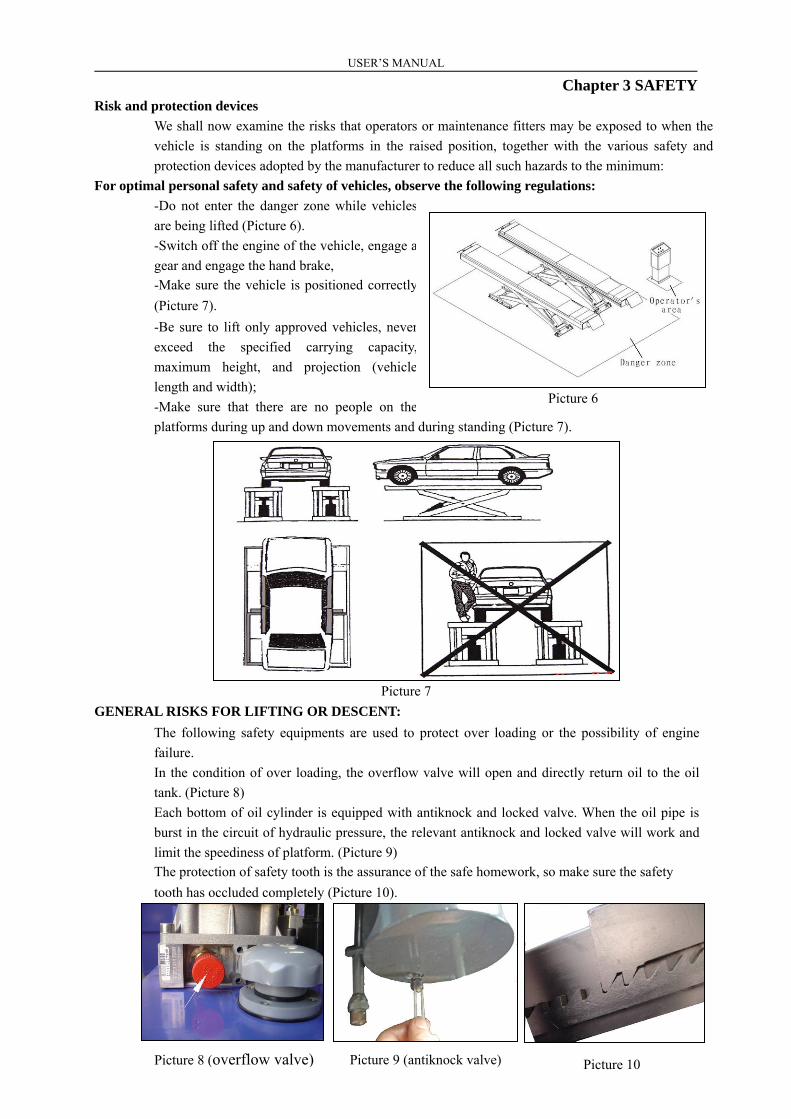
We shall now examine the risks that operators or maintenance fitters may be exposed to when the
vehicle is standing on the platforms in the raised position, together with the various safety and
protection devices adopted by the manufacturer to reduce all such hazards to the minimum:
For optimal personal safety and safety of vehicles, observe the following regulations:
-Do not enter the danger zone while vehicles
are being lifted (Picture 6).
-Switch off the engine of the vehicle, engage a
gear and engage the hand brake,
-Make sure the vehicle is positioned correctly
(Picture 7).
-Be sure to lift only approved vehicles, never
exceed the specified carrying capacity,
maximum height, and projection (vehicle
length and width);
-Make sure that there are no people on the
platforms during up and down movements and during standing (Picture 7).
GENERAL RISKS FOR LIFTING OR DESCENT:
The following safety equipments are used to protect over loading or the possibility of engine
failure.
In the condition of over loading, the overflow valve will open and directly return oil to the oil
tank. (Picture 8)
Each bottom of oil cylinder is equipped with antiknock and locked valve. When the oil pipe is
burst in the circuit of hydraulic pressure, the relevant antiknock and locked valve will work and
limit the speediness of platform. (Picture 9)The protection of safety tooth is the assurance of the safe homework, so make sure the safety
tooth has occluded completely (Picture 10).
Picture 7
Picture 10
Picture 6
Picture 8 (overflow valve) Picture 9 (antiknock valve)

USER’S MANUAL
9
Chapter 3 SAFETY
There is nothing abnormal should be left on the safety modules to prevent safety gear from occlude
normally.
RISKS FOR PERSONNEL
This heading illustrates potential risks for the operator, maintenance fitter, or any other person
present in the area around the lift, result from incorrect use of the lift.
RISK OF CRUSHING:
Possible if the operator controlling the lift is not in the specified position at the control panel.
When the platforms (and vehicle) are lowering the operator must never be partly or completely
underneath the movable structure. Always remain in the control zone.
RISK OF CRUSHING (PERSONNEL):
When the platforms and the vehicle are lowering personnel are prohibited from entering the area
beneath the movable parts of the lift. The lift operator must not start the maneuver unit it has been
clearly established that there are no person in potentially dangerous positions.
RISK OF IMPACT
Caused by the parts of the lift or the vehicle that is positioned at head height.
When, due to operational reasons, the lift is stopped at relatively low elevations personnel must be
careful to avoid impact with parts of the machine not marked with special color.
RISK OF VEHICLE MOVING
Caused by operations that involving the application of force sufficient to displace the vehicle
(picture 12).
In the case of large or particular heavy vehicles, sudden movement could create an unacceptable
overload or uneven loads haring. Therefore, before lifting the vehicle and during all operations on
the vehicle, make sure that it is properly stopped by the hand brake.
RISK OF FALLING (VEHICLE)
This hazard may arise in the case of incorrect positioning of the vehicle on the platforms,
overweight of the vehicle, or in the case of vehicles of dimensions that are not compatible with the
capacity of the lift.
RISK OF VEHICLE FALLING FROM LIFT
This hazard may arise in the case of incorrect positioning of the vehicle on the platforms,
Picture 11

USER’S MANUAL
10
Chapter 3 SAFETYincorrect stopping of the vehicle, or in the case of vehicles of dimensions that are not compatible
with the capacity of the lift.
Never attempt to perform tests by driving the vehicle while it is on the platforms
Never leave objects in the lowering area of the movable parts of the lift.
RISK OF SLIDE
Caused by lubricant contamination that of the floor around the lift. The area beneath and
immediately surrounding the lift and also the platforms must be kept clean. Remove any oil spills
immediately. When the lift is fully down, do not walk over the platforms or the cross-pieces in
places that are lubricated with a film of grease for functional requirements. Reduce the risk of
slipping by wearing safety shoes (Picture 14).
RISK OF ELECTRIC SHOCK
Risk of electric shock that in area of the lift housing electrical wiring.
Do not use jets of water, steam solvents or paint next to the lift, and take special care to keep such
substances clear of the electrical control panel.
RISKS RELATED TO INAPPROPRIATE LIGHTING
The operator and the maintenance fitter must be able to assure that all the areas of the lift are
properly and uniformly illuminate compliance with the laws in force in the place of installation.
RISK OF COMPONENT FAILURE DURING OPERATION
The manufacturer has used appropriate materials and construction techniques in relation to the
specified use of the machine in order to manufacture a reliable and safe lift. Note however, that the
lift must be used in conformity with manufacturer’s prescriptions, and the frequency of inspections
and maintenance works recommended.
RISK RELATED TO IMPROPER USE
Persons are not permitted to stand or sit on the platforms during the lift maneuver or when the
vehicle is already lifted.
The handling of safety devices is strictly forbidden.
Never exceed the maximum carrying capacity of the lift, make sure the vehicles to be lifted
have no load.
It is therefore essential to adhere scrupulously to all regulations regarding use, maintenance and
safety contained in this manual.
Picture 13Picture 12
Picture 14(slide)

USER’S MANUAL
11
Chapter 4 INSTALLATION
Skilled and authorized personnel only should be allowed to perform these operations, follow
all instructions shown below carefully, in order to prevent possible damage to the car lift or
risk of injury to people. Be sure that the operating area is cleared of people.
Skilled technicians only appointed by the same manufacturer or by authorized dealers, are
allowed to install the car lift. Serious damage to people and equipment can be caused if this rule
is not followed.
INSTALLATION REQUIREMENTS
The car lift must be installed according to the specified safety distances from walls must be 1000
mm at least, taking into consideration the necessary space to work easily. Further space for the
control site and for possible runways
in case of emergency is also
necessary; the room must be
previously arranged for the power
supply and pneumatic feed of the car
lift. The room must be 3500 mm in
height; at least, the car lift can be
placed on any floor, as long as it is
perfectly level and sufficiently
resistant.
-All parts of the machine must be
uniformly lit with sufficient light to
make sure that the adjustment and maintenance operations specified in the manual can be
performed safely, and without areas of shadow, reflected light, glare and avoiding all situations
that could give rise to eye fatigue.
-The lighting must be installed in accordance with the laws in force in the place of installation.
-The thickness and leveling of the base concrete are essential.
-Thickness of concrete ≥ 150mm, the leveling of whole length ≤10mm.
LOCATION OF CAR LIFT
Before positioning the lift on the ground check, check the level of the equipment basic. If it is
not a flat basic, insert the adjustment feet on the base (picture 16 & 17).
Place the lift as required following the instructions shown on picture 4.
Lift the two platforms (picture 18 & 19) with a crane, then place them at the height of about
1000 mm, and make sure the mechanical safety device are on.
Picture 16 Picture 17
Picture 15

USER’S MANUAL
12
Chapter 4 INSTALLATION
The turntable position is located at the front of vehicle direction. And the yellow and black safety stripes
are applied on the external side of platforms.
To avoid the unexpected lift closure due to mechanical safety device release insert wooden
pieces in the inner part of the base frame.
Pay attention not to work under the lift until the hydraulic system has not been completely
filled with hydraulic oil.
To insert the lift into the recess, sling the lift as described picture 20 and pay attention not
to damage the hoses and electrical cables.
Before placing the pneumatic and hydraulic hoses to the control unit, stick adhesive tape
on the pipe fittings in order to protect the hoses from dust and impurities which could
damage the hydraulic system.
Perform electric, hydraulic and pneumatic
connections, follow carefully the relevant
numbering. Regarding the proper connections
necessary to make the car lift perfectly working,
see the following chapters.
ROLLING JACK INSTALLATION
Adjust the distance of the rolling jack; put the rolling
jack between the slide tracks.
Adjust the platform to make sure the sliding of the
rolling jack (Picture 20).
Hydraulic line and air line installation for lift:
It is critical that you protect the connections and fittings of the hydraulic lines and that you take
measures to prevent debris from entering the lines. Lay out the high pressure hydraulic lines for
the lift. Connect the hydraulic lines to the lift according to the hydraulic diagram on page-22..
The supply line (8 mm × 5 mm) is connected to the air inlet connection to the solenoid air valve
inside the control box (picture 21).
Picture 20
Picture 19
Picture 18

USER’S MANUAL
13
Chapter 4 INSTALLATION
Connection of Electrical
Connect the electrical according to the electric wiring diagram.
Connection of power supply:
The electrical service to the lift should be installed only by qualified personnel. Before
connecting the electrical service to the lift, be sure main power has been turned OFF. The electric
wiring diagram is arranged by the manufacturer for operating at 400V three-phase. Connect the
live wires (3×2.5 mm2) for the power supply to terminals L1#, L2#& L3# inside the control box.
And connect the earth wire (1×1.5 mm2) to the terminals PE# .If the power requirement for the
lift is 220 VAC connect the electrical according to 220V two-phase. Live wire connect to
terminal L3, and neutral wire connect to terminal N#. The control box/panel must be properly
grounded for safety.
Connection of up limit switch(SQ1) (picture 23):
For detail connection, please see electrical drawing.Connection of lower limit switch(SQ2) (picture 24):
For detail connection, please see electrical drawing.Connection of photocell(PH) (picture 25):
For detail connection, please see electrical drawing.
Picture 23 (up limit switch) Picture 24 (lower limit switch)
Picture 25 (photocell position)
Picture 22 (air cylinder)Picture 21(Solenoid air valve)

USER’S MANUAL
14
Chapter 5 ADJUSTMENT
Anchor bolts installation:
-Adjust the parallel of the platform and the distance of two platforms.
-Lock the machine in one safety teeth.
-Pad a shim (picture 16).
-Fix the anchor bolts (16 bolts) with a percussion electric drill (percussion drill bit is of 16, drill
to 120 mm hole and clean the hole. Insert a peg to has a temporarily immobility.
Level adjustment:
Lift two platforms, and lock them on the three or four teeth.
Check the level of two platforms with level bar or the horizontal pipe (picture 26).
Adjust the adjustment screws (picture 27) at tow sides of the base plate. Adjust the level of two
front turntables and the slide plates on two sides at back, thus keep the levelness of error of the
two platform ≤5 mm, and keep the height difference between the two platform ≤10 mm.
The gap between the base plate and ground after adjustment must be filled with iron plate or
concrete and then tighten the anchor bolts.
Level adjustment of the lowest position:
Adjust the level through the adjustment screws (picture 28 when the platform at the lowest
position.
Add Hydraulic Oil check the order of phase:
Add 18 litters of hydraulic oil into the oil tank (the hydraulic oil is
prepared by the user). It is suggested to use Dexron III ATF oil.
Turn off the photocell on the control panel (turn to “OFF”).
Picture 27 (adjustment screws) Picture 28 (adjustment screws)
Picture 26
Picture 29 (oil tank)

USER’S MANUAL
15
Chapter 5 ADJUSTMENT
On the control panel (picture 30), turn on the “MAIN SWITCH”. To click the “UP” button,
check whether the motor turns clockwise (looking downward), if not turn off the “MAIN
SWITCH”, and change the phase of the motor.
Oil make-up adjustment
1 -Close the oil make up stop valve “H”
2 -Press “UP” button, and thus the left platform
(looking from machine head direction) is lifted to
about 1000mm.
3 -Press the “DOWN” button to lower the left
platform to the lowest position. When reach to the
lower limit swith, the platform will stop automatically
The operator need to release 'DOWN' button and press 'LOCK SEC.DOWN' to let the
platform go down to bottom.
4 -Then lift it up to approximately 1400mm.
5 -Open the oil make up stop valve “H”.
6 -Press “UP” button, and the right platform (looking from machine head direction) is lifted to
about 1000 mm.
7 -Press “DOWN” button to lower the platform to the lowest position.
8 -Repeat the lifting and lowering process for 6-7 times to vent air automatically.
9 -Then lift the right platform to 1400mm. (The two platforms are lifted to the same height).
10 -Finally close the oil make up stop valve “H”.Check and adjust the limit switch of the lift assembly. Check and ensure no oil leakage of the hydraulic line
and air leaks in the air supply line.
Turn on “PHOTOCELL” button to let the photocell working to protect the lift only to be
operated at the same level. And considering about the safety of control, please remove the
key when it’s in normal working.
Picture 31
Picture 30 (operation panel)

USER’S MANUAL
16
Chapter 6 OPERATION
Test with Vehicle
When functioning all the above are normally test the lift with a vehicle load. If the lift operates
normally under load, it can then be put into service.
-Clear obstacles around lift before operation.
-During lifting or lowering, no person is allowed to stand near the two sides and beneath
the machine, and no person is allowed on the two platforms.
-Avoid lifting super heavy vehicles.
-When lifting vehicle, the wheel chocks and hand brake should be used
-Pay attention to the synchronization of the lifting and lowering. If any abnormal is found,
stop the machine timely, check and remove the trouble.
-When locking the main machine, the two platforms should be kept at the same height.
-When the equipment is not used for a long time or over night, the machine should be
lowered to the lowest position on ground, and remove vehicle, and cut off power supply.
Instructions on electric operation:
Lifting:-Press “UP” button, the platforms are being lifted. The platforms will stop lifting when touchthe up limit switch.-Release “UP” button, the platforms stop lifting.Locking:
To perform vehicle maintenance or alignment, the lift must be locked before repairs oradjustments can be conducted. Press “LOCK SEC.DOWN” button. The main lift will belowered slightly to allow the safety mechanism to fully engage.Lowering:
When press “DOWN” button, the platforms will first lift slightly for a couple of seconds todisengage the safety mechanism, and then lower. The buzzer rings during the whole loweringprocess.But when keep pressing “DOWN” button, the platform will stop automatism at 700 mm when touch the
lower limit switch. Release “DOWN” button and press "LOCK SEC. DOWN". The platform will descend
again.
Up limit Switch Precaution
When the lift is lifted to its set-limit height, the platforms will stop because of touching the up limit switch.
At this height, in order to lower the lift, you must press and hold the “DOWN” button for a couple of
seconds for the lift to lower.
Emergency stop:When the machine has abnormal or is doing car maintenance, push “EMERGENCY STOP”button and locking, cut off all the operation circuit, other operation can not be worked.
Photocell Switch:It is a special device to stop the car lift during lowering or lifting operations, when the leveldifference between the two platforms is more than 5 cm, or when something obstructs them.

USER’S MANUAL
17
Chapter 7 MAINTENANCE CARE
Maintenance and care:-The upper and lower sliding blocks must be kept clean and lubricate.
-All bearings and hinges on this machine must be lubricated once a month by using an oilier.
-The side sliding plates must be disassembled and greased once a year.
-The hydraulic oil must be replaced one time each year, the oil tank and filter should be cleaned
when replacing hydraulic oil. The oil level should always be kept at upper limit position.
-The machine should be lower to the lowest position when replace hydraulic oil, then let the old oil
out, and should be filtering the hydraulic oil.
-The compressed air used in pneumatic safety devices must be filtered through water to ensure long
time reliable operation of the cylinder and air valve DQ for driving the safety pawl.
Emergency manual operation for lowering (power failure):
When lowering through manual operation, should observe the condition of platform at any time
because there are vehicles on the platform. If there is something abnormal, screw down oil loop
valve immediately.
The process of manual operation:
-Firstly connect a manual pump (prepared by user) to the main hydraulic line (picture 32), and lift the
platforms to disengage the safety mechanism. Use thin iron bar to fill up safety mechanism.
-Switch off the power button (avoid abruptly incoming electricity). Open the back cover of control
box to find the descent valve A for lowering.
-Loosen manual oil loop stud (picture 33), and then the platform begins lowering.
-After the machine has been lowered, screw down manual oil loop stud timely, the process of manual
lowering comes to the end.
Picture 32 (manual pump) Picture 33 (descent valve)

USER’S MANUAL
18
Chapter 8 TROUBLESHOOTING
Skilled personnel only are allowed to perform the operations.
Failure Cause Troubleshooting
The motor does not runin lifting operation.
① Connection of powersupply wires or zerowire is not correct.
Check and correct wire connection.
② The AC contactor in thecircuit of the motor doesnot pick up.
If the motor operates when forcing the contactordown with an isolation rod, check the controlcircuit. If the voltage at two ends of the contactorcoil is normal, replace the contactor.
③ The limit switch is notclosed.
Short-circuit terminal 100# and 102#, which areconnected with the limit switch, and if the troubledisappears, check the limit switch, wires andadjust or replace the limit switch.
In lifting operation, themotor runs, but there isno lifting movement.
① The motor turns reverse. Change the phases of the power supply wires.② Lifting with light load isnormal but no liftingwith heavy load.
The set safe pressure of the overflow valve may beincreased by turning the set knob right wardslightly.The spool of the lowering solenoid valve is stuckby dirt. Clean the spool.
③ The amount of hydraulicoil is not enough.
Add hydraulic oil.
④ The stop valve” is notopened.
Turn right and open the “stop valve and supplyhydraulic oil to main oil cylinder.
When press“DOWN” button, themachine is notlowered.
① The safety pawl are notreleased form the safetyteeth.
First lift a little and then lowering.
② The safety pawl is notlifted.
The air pressure is not enough or the safety pawlis stuck.
③ The solenoid air valvedoes not work.
If the solenoid air valve is energized, but does notopen the air loop, check or replace the solenoid airvalve.
④ The descent valve isenergized but does notwork.
Check the plug and coil of the descent valve andcheck the right turn tightness of its end copper nutand so on.
⑤ The hydraulic oil has toohigh viscosity or frozen,deteriorated (in Winter).
Replace with 20# hydraulic oil in accordance withthe instruction book.
The machine lowersextremely slowly under
normal loads.
The “antiknock valve” forpreventing oil pipe burst isblocked.
Remove or close air supply pipe and thus lock thesafety pawl of the machine without lifting of thesafety pawl. Remove the “antiknock valve” fromthe oil supply hole at the bottom of the oilcylinder, and clean the “antiknock valve”.
The right and leftplatforms are not
synchronous and not inthe same height.
① The air in the oilcylinder is not ventcompletely.
Refer to “Ⅶ. Oil Make-up adjustment”.
② Oil leakage on oil pipeor at its connections.
Tighten oil pipe connections or replace oil sealsand then make-up oil and adjust levelness.
③ The “oil make-up stopvalve” can not be closedtightly and almostmake-up oil and adjustevery day.
Replace oil make-up stop valve, and then make-upoil and adjust.
Noisy lifting andlowering.
① Lubrication is notenough.
Lubricate all hinges and motion parts (includingpiston rod) with machine oil.
② The base or the machineis twisted.
Adjust again the levelness of the machine, and fillor pad the base.

USER’S MANUAL
19
Appendix
Hydraulic schematic diagram:1 main cylinder 8 electromagnetic valve of descent
2 slave cylinder 9 flow control valve
3 assist cylinder 10 gear pump
4 antiknock valve 11 pump motor
5 stop valve 12 filter
6 check valve 13 oil tank
7 overflow valve
8 descent valve
9 throttling valve
10 gear pump
11 pump motor
12 filter
13 oil tank
Oil pipe connection diagram:
A descent valve B motor C overflow valve D joint wire box E check valve

USERUSER’’SS MANUALMANUAL
20
Appendix
For the exploded drawings, please take the actual lift as standard!
Exploded view of platform:
Exploded view of scissor:

USERUSER’’SS MANUALMANUAL
21
Hydraulic cylinder exploded view:
Parts list
Parts list of scissor
Item Description Qty Item Description Qty
1 Vertically pin axle of main lift 821
Lock device(for big cylinder) 1
2 Oil-less axletree 3030 8 Lock device(for small cylinder) 1
3 Snap ring φ30 18 22 Snap ring φ34 2
4 Sub connecting rod 223
Cylinder ream-axle(big) 1
5 Snap ring φ36 4 Cylinder ream-axle(small) 1
6 Piston Rod Supporting Hinge Axle 2 24 Oil-less axletree 3625 4
7 Upper slide block 4 25 Nut M16 32
8 Main connecting rod 2 26 hexagon head bolt M16×50 28
9 Oil-less axletree 3645 4 27 Down bracket stand 2
10 Locknut M24 4 28 Ground bolt 16
11 Washer φ24 4 29 Short adjust shim 4
12 Centre ream-axle 2 30 lower guide notch 4
13 screw M5×10 11 31 lower slide block 4
14 hose block 3 32 Attrition-lessen board 4
15 socket cap screw M5×50 8 33 lower slide stand board 2
16 spring (lock) washer φ5 8 34 Long adjust shim 4
17 Air cylinder 2 35 Piston Rod Supporting Hinge Axle2 2
18 Air hose block 6 36 Cylinder ream-axle2 2
Assistant cylinder

USERUSER’’SS MANUALMANUAL
22
19 Safety-jaw 2 37 assistant cylinder 2
20Hydraulic Cylinder 120 1
Hydraulic Cylinder 100 1
Parts list of platform
Item Description Qty Item Description Qty
1 Front wheel stop 2 13 Ball 54
2 hexagon head bolt M10×15 16 14 Washer φ8 54
3 Washer φ10 16 15 hes nut M8 108
4 Front wheel stop rack 2 16 Block up 2
5 crossbeam 2 17 hexagon head bolt M8×15 8
6 turntable keeps off the block(90) 2 18 Back wheel stop rack 2
7 turntable keeps off the block(295) 2 19 Back wheel stop 2
8 Side slide plate 2 20 Placket pin φ3 4
9 Sliding-proof pin 4 21 hexagon head bolt M16×80 4
10 Spring 8 22 Nut M16 4
11 Haul hook 8 23 turntable keeps off the block(400) 2
12 Nut M6 8
Parts list of master & slave cylinder
Item Description Qty Item Description Qty
1 Dust-proof ring 1 12 Assembled poly 1
2 Wearable ring φ24 2 13 Dust-proof ring 1
3 Poly sealing 2 14 Wearable ring D24 2
4 Hydraulic Cylinder cover 120 1 15 Hydraulic Cylinder cover 100 1
5 O-ring 1 16 O-ring 1
6 Hydraulic Cylinder canister 120 1 17 Hydraulic Cylinder canister 100 1
7 φ14 Assembled ring 2 18 Piston Rod 50 1
8 Hydraulic pipe connecting 2 19 Piston 100 1
9 Piston Rod ring 2 20 Assembled poly 1
10 Piston Rod 66.3 1 21 Anti-explosive valve 2
11 Piston 120 1 22 screw M8×12 2
Parts list of assist cylinder
Item Description Qty Item Description Qty
1 Dust-proof ring 1 7 Assembled poly 2
2 Wearable ring φ24 2 8 Piston 75 2
3 Hydraulic Cylinder cover 75 2 9 Piston Rod 45 2
4 Hydraulic Cylinder cover 75 1 10 Piston Rod ring 2

USERUSER’’SS MANUALMANUAL
23
5 φ14 Assembled ring 1 11 screw M8×12 2
6 Hydraulic pipe connecting 1 12 Oil-less axletree 3030 2