large scale solar thermal - lowtemp.eu
TRANSCRIPT

Large scale solar thermalRequirements, opportunities, integration into DH-networks

LowTEMP training package - OVERVIEW
2
Introduction
Intro Energy Supply Systems and LTDH
Energy Supply Systems in Baltic Sea Region
Energy Strategies and Pilot Projects
Methodology of Development of Energy Strategies
Pilot Energy Strategies –Aims and Conditions
Pilot Energy Strategy – Examples
Pilot Testing Measures
CO2 emission calculation
Financial Aspects
Life cycle costs of LTDH projects
Economic efficiency and funding gaps
Contracting and payment models
Technical Aspects
Pipe Systems
Combined heat and power (CHP)
Large Scale Solar Thermal
Waste & Surplus Heat
Large Scale Heat Pumps
Power-2-Heat and Power-2-X
Thermal, Solar Ice and PCM Storages
Heat Pump Systems
LT and Floor heating
Tap water production
Ventilation Systems
Best Practice
Best Practice I
Best Practice II
Business models and innovative funding structures
LCA calculation
Intro Climate Protection Policy and Goals

Solar radiation and heat production
Overview - Solar thermal systems & operating modes
• General principle of flat plate collectors
• General principle of evacuated tube collectors
• Indirect-flow evacuated tube collectors / heat-pipe principle
• Direct-flow evacuated tube collectors / Compound Parabolic Concentrator (CPCs)
• Characteristics of the heat medium
Installation & planning requirements
• Collector orientation / tilt & efficiency
• Collector arrangement / Collector circuitry
• Tichelmann-Principle
• Stagnation handling
Overview
3

Technical & economic efficiency
• Difference betweeen collector & system yield
• Annual cover ratio
• Increasing annual solar coverage through storage
• Key questions regarding investment costs & economic efficiency
Feed-in principles
• Hydraulic integration of solar thermal feed-in
• Solar heat combined with other fuels
ANNEX & Overview about Pilot Projects
Overview
4

approximate solar radiation in Central Europe at midday : +/- 1000 watts / m2
(under perfect weather conditions)
annual average of solar radiation in Central Europe: +/- 125 W/ m2
(about 1/8 of perfect conditions)
approx. average solar radiation on collector:
1/8 x 24h (3h per day)
or 1/8 x 8760 h/a = +/- 1100 operating hours /a
+/- 1100 kW/h per m2a
Solar radiation & heat production
5
Source of example: Arbeitsgemeinschaft QM Fernwärme [1]
Source: pixabay

6
Source: Meteonorm 2008 [2]
Solar radiation & heat production
Annual yield depends on many factors
• weather
• collector type
• site specifications
• plant dimensioning and energy utilization
• installation angle
• etc…

Overview - Solar thermal systems & operating modes
7
Source & copyright: LowTEMP. Stefan Simonides [4]Source: Ritter XL Solar [3] Source: Ritter XL Solar [3]
Where to place solar heat collectors?
• Ground mounted solar collectors
(cheapest solution; depending on land prices, distance to the existing pipe system or consumer, general heat utilization, storage & many other parameters)
• Roof mounted solar collectors (interesting for large and flat rooftop areas)
Most common collector types on the market?
• Flat plate collectors
• Evacuated tube collectors

Overview - Solar thermal systems & operating modes
8
Source: sunpower & baunetz_wissen ; adjustedby AGFW-Project GmbH [5]

Flat plate collectors are using a flat absorber plate that is isolated with mineral wool, polyurethane foam or other materials
This isolation is less efficient than the vacuum isolation of evacuated tube collectors
High performance flat plate collectors are operating with copper absorbers
General principle of flat plate collectors
9
Source & copyright: Stefan Simonides

10
General principle of flat plate collectors
Source: sunpower (see [5])
approx. production of 500-550 kWh annual yield per gross collector surface
Reach operating temperatures from 30 to 80 °C
If well planned, can reach stagnation temperatures from 150-200 °C
Can be installed in series or parallel connection
Installation angle variable
FPCs usually work with a medium from water and antifreeze fluid

General principle of evacuated tube collectors
11
Evacuated tube collectors are typically designed with parallel rows of double-hulled glas tubes
The very high thermal insulation can be reached by thevacuum in the outer tube
Heat pipes are transmitting the heat to the heat medium (indirect flow) or direct flow lines transport the heat medium in an „U-shape“ through the inner glass tube
Higher temperature levels can be achieved (above 200 °C upto 350°C)
higher heat extraction efficiency compared with FPCs in the temperature range above 80°C
Efficiency levels are also higher than flat plate collectors
Higher investment costs then flat plate collectors
Source: Viessmann Werke [8]
Source: Ritter-XL-Solar [7]

General principle of evacuated tube collectors
12
vacuumglas
absorber
Heat pipeHeat exchange
vacuumglas absorber
vacuum glas absorber
Heat pipe Heat exchange
vacuum glas absorber
Flow line
Flow line
Return line
Return line
Source: Klaus Oberzig · 2014; translated & adjusted [9]
Sydney tube with heat pipe (indirect flow)
Evacuated tube & heat pipe principle (indirect flow)
Evacuated tube (direct flow)
Evacuated tube or Sydney tube (direct flow)

Indirect-flow evacuated tube collectors or heat-pipe principle
13
Heat transfer tube is installed on the backside of an absorber panel
The tube is filled with a heat medium (mostly water or alcohol under negative pressure)
The heat transfer takes place at the top of the tube
(condensation of heat medium released heat is transferred to the collector pipe system
condensate of heat medium returns to the bottom of the glass tube and heats up again)
Works also at days with low solar radiation, because condensate
evaporates already at low temperatures of about 25 °C (collector temperature)
Less pressure loss due to direct heat exchange at the flow line

Evacuated tube collectors
14
outer glass tube
vacuum
Coating (e.g. black-chrome or black-nickel)
inner glass tube
inner glass tube
copper tubes
heat transfer medium

Compound Parabolic Concentrator (CPCs)
15
sunlight
innerglass tube
outer glass tube
Heat-conductingprofile (e.g. copper)
vacuum
High selective coating
Capability of reflecting to the absorber all of the incident radiation within wide limits
changing solar orientation can be reduced by using a trough with two sections of a parabola facing each other
By using multiple internal reflections, any radiation entering the aperture within the collector acceptance angle finds its way to the absorber surface
High investment costsSource: Frank Tebbe [10]

Characteristics of the heat medium
16
Important characteristics for SDH heat medium:
High temperature stability
Low viscosity (due to heat capacity)
High heat capacity
Environmental compatibility
Corrision protection (demineralised water etc.)
Frost protection (usually mixture of water and alcohol used; e.g Propylene Glycol)
SDH-Heat medium ≠ district heating water
Heat is exchanged at the heating station / storage tank via heatexchangers
Heat is exchanged at the top of evacuated tube-collectorsoperating with indirect flow
Source: Volker Quaschning [11]

Installation & planning requirements
17
Collector orientation / tilt (set-up angle) & efficiency
Source: Abhishek Dutta 2019 [12]

Installation & planning requirements
18
Collector orientation / tilt & efficiency
absorber gets the most efficient energy when collector axis is absolute vertical to the sun rays
change related to hour and season
hence the collectors must be oriented in the latitude right angle and slope
For Europe usually 25 ̊ to 45 ̊ is the most ideal “solar altitude angle” to mount, but also angles up to 60° e.g. on rooftops can be found
The higher the tilt the higher the collector yield during winter times / days with low solar radiation
high tilts minimize peaks and thermal stagnation in summer, but also the temperature level
Orientation generally always depends on the site specific operation / planned heat utilization (space heating / domestic hot water preparation / both / with or without seasonal storage) / heat demand etc.

Installation & planning requirements
19
East SE South SW West
Source of example: Sabine E. Rädisch 2014 / Paradigma [13]
Collector orientation / set-up angle & efficiency
Calculative EXAMPLE for different varieties of solar thermal collectors. • Location: Würzburg, Germany• Set-up angle: 75° orientation: varying• Average collector temp.: 75 C°
Calculative EXAMPLE for different varieties of solar thermal collectors. • Location: Würzburg, Germany• Orientation: South; tilt: varying• Average collector temp.: 75 C°

Installation & planning requirements
20
Collector arrangement & circuitry
large scale solar-thermal plants can be designed in series and/or parallel connections
Series connection
high pressure losses
high pump capacity
even flow rates
High
Less pipinginstallation / lowerinvestment costs
Parallel connection
low pressure losses
less pump capacity
Tichelmann principlenecessary for even flow rates
Lower flow rates
∆T depends on collectors in series connection
for large scale SDH-plantsSeries & parallel connection. Own illustrations AGFW-Project GmbH

„Tichelmann-principle“:
• equal length ratio between flow line & return line
• Heat medium always covers same distance
• Equal pressure losses within the system
• Equal mass flux distribution
Higher piping needed
Fewer regulation effort needed e.g. through control valves
Installation & planning requirements
21
Tichelmann-principle. Own illustrations AGFW-Project GmbH

Stagnation handling
22
Design Temperature
Design temperature is the maximum temperature a solar thermal collector or collector loop part can stand without being damaged. The design temperature of the entire solar loop is determined by the collector loop component with the lowest design temperature.
Operation temperature
Operation temperature is defined as the maximum temperature of a solar thermal collector or the collector loop where “normal” operation shall be pursued.
determined by maximum storage temperature
determined by heat demand of the connected DH-system
Stagnation
Stagnation describes the state of a solar thermal system in which (by any reason) the flow in the collector loop is interrupted although sufficient solar irradiance is available for operation of the collector loop.
the fluid in the solar thermal collector is heated up to a temperature where the absorbed energy equals the losses
(Source: Frank, E., Mauthner, F., & Fischer, S. (2015). [14]

Stagnation handling
23
(Quoted from Frank, E., Mauthner, F., & Fischer, S. (2015). [14]
„Stagnation handling…
…if stagnation is an accepted
operation mode!“
„Overheating prevention…
... If stagnation is not an accepted
operation mode!“
Keymark-Certificates: http://www.estif.org/solarkeymarknew/
Constructional precautions, security concept with regard to plant-dimensioning have to be THE importantaspects in the planing phase!
(Example of a keymark-certificate. Source: www.estif.org )

Effects of stagnation:
Pressure increase and steam formation in the collector
Steam development in the solar circuit
High stress on the system components (e.g. pump gaskets)
Possible cracking of glycol in the heat transfer fluid
Handling stagnation:
Drainage of the solar fluid (especially necessary for glycol medium before stagnation state)
Disable pumps & overpressure management
Active cooling e.g. with groundwater and a second heat exchanger (extra well and absorption well will be needed)
Accepting stagnation as operation mode needs to considered and planned within the planning and implementation phase
Stagnation handling
24

Technical & economic efficiency
25
… due to warming up in the morning and cooling down at night
… in pipes and valves
… due to storage
… due to stagnation
… due to active frost protection
… due to antifreeze fluid
… due to heat exchangers
Difference occurs…
Collectoryield
Maximum system yield
The difference between collector yield andmaximum system yield can be roughlyestimated by taking 10 % of the annualradiation
Difference betweeen Collector & system yield
Source: Own illustration AGFW-Project GmbH

Annual cover ratio
26
Cover ration depends on:
Integration of solar heat production in DH-systems (feed-in point: flow line / return flow)
Planned heat utilization and operating temperature level
(Domestic hot water preparation, space heating, floor heating, etc.)
Building structure (development area, existing building structure)
Structure of the solar system (buffer storage, seasonal storage or direct integration)
Direct or indirect feed-in
No determined reference values! (cover ratio needs to be estimated for each specific project) SDH-plant can approx. reach between 30-60 % of the annual demand of domestic hot water preparation
(complete coverage in summer) Seasonal storage can increase the annual solar cover ratio by boosting stored water e.g. with a heat pump
in transition periods

Increasing annual solar coverage through storages
27
Source: Mathilde Kolbe 2018 [15]

Increasing annual solar coverage through storages
28
Source:ikz.de (translated) [16]
Heat storage (tank)(60 to 80 kWh/m3)
Pit store(30 to 80 kWh/m3)
Pie store (geothermal probe)(15 to 30 kWh/m3)
Aquifer storage(30 to 40 kWh/m3)
Storages options:
Buffer storages (daywise storage)
Seasonal storages (on the left)

Feed-in principles – decentral / central
29
„Decentral“: solar thermal plant is not close located to another major heat generator
Central: feed-in point can be a transfer station (Solarthermal plant is located next to another heatgenerator e.g. heat plant / cogeneration unit )
Source: Solites (translated) [17]

Feed-in principles – decentral
30
(Figure & Quoted from Solar District Heating (SDH) (2012) [18].
Required temperature hub in the heat generator is defined byflow and return line of the heating grid
Solar plant has to be operated at matched flow volumes, adjusted to the required flow temperature
Feed-in pump has to overcome pressure differences betweenreturn and flow (could come to several bar)
+ no change in return temperatures
- high pump capacities needed

Feed-in principles – decentral
31
(Figure & Quoted from Solar District Heating (SDH) (2012). [18]
Operating temperatures of solar plant lowest compared toother feed-in modes
High solar yields can be expected
No pumping energy required
Constant mass flow in collectors
Grid operators need to install a flow resistance to control feed-in by solar plant
High return temperatures are not favourable

Feed-in principles – decentral
32
(Figure & Quoted from Solar District Heating (SDH) (2012). [18]
High collector operating temperatures needed
Low solar thermal efficiency and yields due to high temperature level

33
Feed-in principles – central
Source: Solites (translated) see [17]
Heat transfer takes place with heat exchangers at the central heating station
clear distinction between solar cycle and DH-systems
Feasible combination of solarthermal plant with other
heat generating technologies possible

Technically solar heat can be combined with any other energy source
The economical and environmental feasibility relies on multiple factors and needs to be estimated for each case!
Few examples:
• Increase of Return-flow
• Saving primary energy: increase of return flow temperature / coverage of domestic hot water preparation in summer)
• High return flow temperatures not always wanted by grid operators
• In combination with a cogeneration plant
• Solar thermal plants could lower output for electricty production
SDH combined with other heat generating technologies
34

Cost of land
Collectors
Collector field installation including piping in the field
Anti-freeze fluid
Transmission piping (collector field to heat exchanger unit)
Heat exchanger (HX) unit (including pumps, expansion vessels, control, etc.)
Connection to existing DH-systems
Storage
Control system
Design & optimization
Miscellaneous (e.g. building, ground shaping, fence, plant management etc.)
Key points regarding investment & operating costs
35
(Quoted from Solar District Heating (SDH) (2012). Solar district heating guidelines – Collection of fact sheets WP3-D3.1 & D.3.2. Page 8 Fact sheet 2.3

Heat demand & dimension of the plant
Storage size / seasonal storage needed (if, which other heat source e.g. heat pump will be needed?)
Required landsize & price need to be evaluated with legal issues and construction law
Which solar thermal system is needed? / Which temperature level is necessary?
What are the existing structures of heat generation? What will be the future solar feed-in scenario?
piping expenses
How much should be the estimated solar thermal heat coverage / annual duration?
Flow pipe / return pipe feed-in or both?
What are the energy savings by other integrated/existing heat sources (e.g. (bio)gas / biomass etc.)?
How much funding is possible?
What are the financing costs (term, interest rate)?
Development of energy costs within the next few years?
Key points regarding investment costs & economic efficiency
36

37
Contact
AGFW-Project GmbHProject company for rationalisation, information & standardisation
Stresemannallee 3060596 Frankfurt am MainGermany
E-mail: [email protected]: +49 69 6304 - 247www.agfw.de
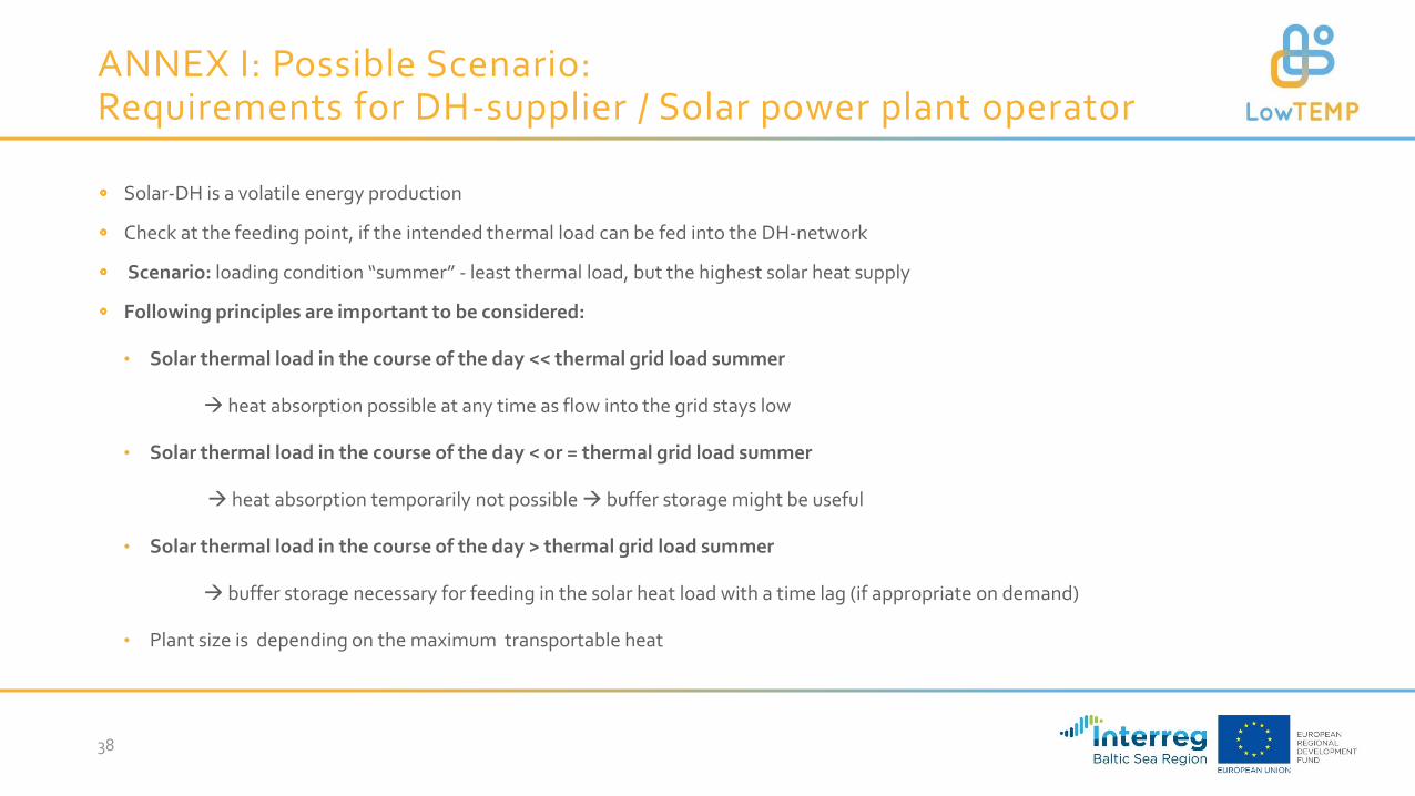
Solar-DH is a volatile energy production
Check at the feeding point, if the intended thermal load can be fed into the DH-network
Scenario: loading condition “summer” - least thermal load, but the highest solar heat supply
Following principles are important to be considered:
• Solar thermal load in the course of the day << thermal grid load summer
heat absorption possible at any time as flow into the grid stays low
• Solar thermal load in the course of the day < or = thermal grid load summer
heat absorption temporarily not possible buffer storage might be useful
• Solar thermal load in the course of the day > thermal grid load summer
buffer storage necessary for feeding in the solar heat load with a time lag (if appropriate on demand)
• Plant size is depending on the maximum transportable heat
ANNEX I: Possible Scenario: Requirements for DH-supplier / Solar power plant operator
38

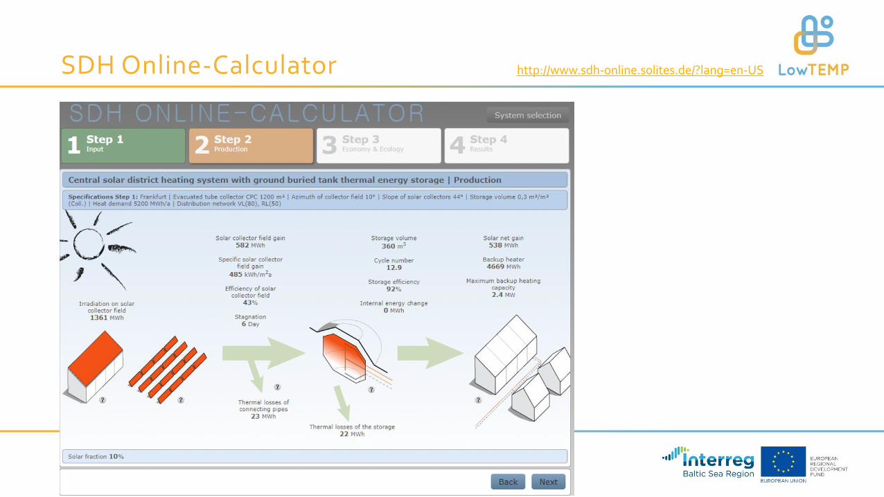
ANNEX II: SDH Online-Calculator –EXAMPLE
39
http://www.sdh-online.solites.de/?lang=en-US

SDH Online-Calculator
40
http://www.sdh-online.solites.de/?lang=en-US
SDH Online-Calculator
41
http://www.sdh-online.solites.de/?lang=en-US

SDH Online-Calculator
42
http://www.sdh-online.solites.de/?lang=en-US

SDH Online-Calculator
43
http://www.sdh-online.solites.de/?lang=en-US

[1] Arbeitsgemeinschaft QM Fernwärme (2017): planning manual District heating
[2] Metenorm 2008: MeteoTest, Bern.
[3] Ritter XL Solar. https://www.ritter-xl-solar.de/anwendungen/solare-fernwaerme/
[4] LowTEMP Project. Copyright Stefan Simonides.
[5] Sunpower. https://www.sunpower-solar.com/Flat-Plate-Solar-Water-Heater-Split-Pressure-Collector-Solar-Keymark-pd207273.html & baunetz_wissen. https://www.baunetzwissen.de/glossar/h/heat-pipe-prinzip-674868. Adjusted by AGFW-project GmbH
[6] Solites. https://www.solites.de/
[7] Ritter-XL-Solar. https://www.ritter-xl-solar.de/
[8] Viessmann Werke. www.viessmann.com
[9] Klaus Oberzig 2014. Solarwärme .Translated & adjusted by AGFW Project-GmbH
[10] Frank Tebbe: http://www.paradigma-tebbe-gmbh.de/solar.htm
[11] Volker Quaschning: https://www.volker-quaschning.de/articles/fundamentals4/index.php
[12] Abhishek Dutta 2019. https://solargyaan.com/solar-altitude-angle-and-solar-azimuth-angle/
[13] Sabine E. Rädisch 2014. Welchen Einfluss hat der Einfallswinkel beim Solarkollektor?. Paradigma. https://blog.paradigma.de/einfallswinkel-beim-solarkollektor/
[14] Frank, E., Mauthner, F., & Fischer, S. (2015). Overheating prevention and stagnation handling in solar process heat applications. International Energy Agency-Solar Heating and Cooling Task, 49.
[15] Mathilde Kolbe 2018. Integration solarthermischer Großanlagen in Nah- und Fernwärme. https://silo.tips/download/integration-solarthermischer-groanlagen-in-nah-und-fernwrme
[16] IKZ 2020. https://www.ikz.de/detail/news/detail/saisonale-waermespeicher/
[17] Solites 2015. In: SolnetBW 2016. Solare Wärmenetze für Baden-Württemberg Grundlagen |Potenziale | Strategien, p. 14. https://docplayer.org/13300142-Solnetbw-solare-waermenetze-fuer-baden-wuerttemberg-grundlagen-potenziale-strategien.html
[18] Solar District Heating (SDH) (2012). Solar district heating guidelines – Collection of fact sheets WP3-D3.1 & D.3.2. Page 2-5 Fact sheet 6.2)
References
44