large scale storage of electrical energy using maglev
TRANSCRIPT
Large Scale Storage of Electrical Energy Using Maglev
James R. Powell and Gordon Danby
Maglev 2000, Laguna, CA 92651
mailto :[email protected] [email protected]
Robert J. Coullahan,
Readiness Resource Group, Inc.4055 S. Spencer Street - Suite 222 Las Vegas, Nevada 89119
James C. Jordan
Maglev Interstate Project, 708 East Broad St., Falls Church, VA 22046
F.H. (Bud) Griffis
Polytechnic Institute of New York University, Six MetroTech Center, Brooklyn, NY 11201 USA
Hyunchul Choi
PhD Student, Polytechnic Institute of New York University, Six MetroTech Center, Brooklyn, NY 11201 USA
ABSTRACT: The MAPS (MAglev Power Storage) system for storage of large amounts of electrical energy is
described. Superconducting Maglev vehicles transport heavy masses from lower to higher elevations.
Electrical input energy from the grid propels the Maglev in the motor mode as it transports the heavy masses to
a higher elevation. The input electrical energy is stored as gravitation energy at the higher elevation. To feed
energy back into the grid on demand, the mass is returned to the lower elevation. Its stored mass is transformed
to electrical energy by the magnetic propulsion system as it operates in generator mode. The 90% efficient
MAPS system can store thousands of megawatt hours at 2 to 3 cents per KWH.
1. WHY MAGLEV FOR ELECTRICAL ENERGY
STORAGE
The US electrical grid is a technology marvel. It
provides ample and reliable amounts of electrical
energy to virtually every person, industrial, and
commercial entity in America on demand, usually
without problems, and at an acceptable cost. Long
distance transmission lines interconnect many large
power generation plants around the United States and
Canada, with millions of users scattered across the
country, transmitting many thousands of megawatts
over distances of many hundreds of miles.
However, there are limitations and concerns about
the US electrical grid. Electrical demand varies
considerably and often rapidly with the time of day,
day of week, and season. Baseload generating plants,
e.g. coal fired and nuclear, cannot meet rapidly
shifting demands, because their time response is too
slow. To react to fluctuating demands, quick
response peaking power plants, usually fueled by
expensive natural gas, are used. Typically, about
20% of the annual kilowatt hours (KWH) consumed
in the US comes from gas fired peaking power plants.
The cost of this energy is substantially greater than
the cost of power from coal fired and nuclear power
plants.
The 21st International Conference on Magnetically Levitated Systems and Linear Drives, October 10-13, 2011, Daejeon, Korea
That is now. The situation becomes worse if the US
begins to shift away from coal fired power plants
towards renewable wind and solar power sources.
The outputs from wind and solar are highly variable
and non-predictable. When the wind blows – which
is typically only 30% of the time – the generated
power may or may not be matched to demand.
Sometimes there will not be demand for the wind
power; other times there will be demand, but the
wind isn’t blowing.
Matching variable output will require new energy
storage technologies. Pumped hydro storage is
practical but has siting restrictions and major
environmental concerns. Total US electrical
generation capacity is 1 million megawatts, while the
pumped hydro capacity is only 22,000 megawatts (1)
– about 2% -- and it’s unlikely to get much larger.
Moreover, potential wind and solar power sources are
often far removed from any possibility of a pumped
hydro storage facility. Also, the output/input energy
efficiency of pumped hydro is only about 70%, so a
substantial fraction of the input power is lost (2).
Compressed air storage in underground cavities is a
recent technology development, but it too has
limitations and concerns. One requires stable
geologic conditions, and output/input power losses
are substantial.
Pumped hydro and compressed air storage fall into
the category of bulk energy storage, with the
capability of storing many hundreds of megawatt
hours at high, but still acceptable cost.
The other energy storage options – flywheels,
batteries, hydrogen fuel cells, thermal, and
superconducting magnetic energy storage (SMES) –
fall into the category of micro energy storage. They
are too expensive and too limited in capacity to store
large amounts of electrical energy. They can play a
very useful dynamic role, however, in helping to
ensure that the various sections of the grid system
connected together have uniform frequency and
phase.
In addition to meeting time varying power demands
and ensuring proper frequency and phasing in the
grid, energy storage systems, particularly bulk
storage systems, can provide insurance against grid
failures due to accidents and sabotage. Several years
ago, some trees fell during a storm in Ohio,
disrupting electrical transmission capability. As a
consequence of propagating failures, the US
Northeast was blacked out for a substantial length of
time. Sabotage is an even greater worry. It can be
physical in nature – blowing up substations and/or
transmission lines, attacking power generation plants,
etc – or it can be cyber in nature – shutting down
power plant controls, substation switches, etc.
Large scale, low cost bulk energy storage would
greatly help ensure that accidents or sabotage would
not shut down large sections of the US electrical grid,
by providing electrical energy for extended periods of
time to make up for the portions that were
temporarily not working.
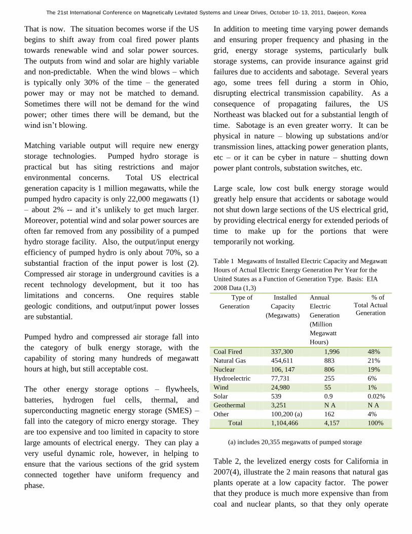
Table 1 Megawatts of Installed Electric Capacity and Megawatt
Hours of Actual Electric Energy Generation Per Year for the
United States as a Function of Generation Type. Basis: EIA
2008 Data (1,3)
Type of
Generation
Installed
Capacity
(Megawatts)
Annual
Electric
Generation
(Million
Megawatt
Hours)
% of
Total Actual
Generation
Coal Fired 337,300 1,996 48%
Natural Gas 454,611 883 21%
Nuclear 106, 147 806 19%
Hydroelectric 77,731 255 6%
Wind 24,980 55 1%
Solar 539 0.9 0.02%
Geothermal 3,251 N A N A
Other 100,200 (a) 162 4%
Total 1,104,466 4,157 100%
(a) includes 20,355 megawatts of pumped storage
Table 2, the levelized energy costs for California in
2007(4), illustrate the 2 main reasons that natural gas
plants operate at a low capacity factor. The power
that they produce is much more expensive than from
coal and nuclear plants, so that they only operate
The 21st International Conference on Magnetically Levitated Systems and Linear Drives, October 10-13, 2011, Daejeon, Korea

Source Cost($/MWH)
Advanced Nuclear 67
Coal 74-88
Gas 313-346
Geothermal 67
Hydroelectric 48-86
Wind 60
Solar 116-312
when baseload plants cannot meet power needs
during high demand periods. The second main
reason is that natural gas power plants can
increase/decrease output generation much more
rapidly than coal and nuclear plants, so they can load
follow much better.
2007(5), illustrate the 2 main reasons that natural gas
plants operate at a low capacity factor. The power
that they produce is much more expensive than from
coal and nuclear plants, so that they only operate
when baseload plants cannot meet power needs
during high demand periods. The second main
reason is that natural gas power plants can
increase/decrease output generation much more
rapidly than coal and nuclear plants, so they can load
follow much better.
If there were electrical storage systems that could be
sited virtually anywhere with no environmental
problems, that could store very large amounts of
electrical energy at low cost per KWH, that were
rapidly responsive, and that had high output/input
electrical efficiency, there would be no need for
natural gas peaking plants – baseload plants could
supply all the power. Energy storage systems would
meet the bulk of the peak power demands, amounting
to approximately 1000 million megawatt hours of
energy generation.
Present energy storage systems cannot meet the peak
power market presently held by natural gas peaking
units. (5) Pumped hydro is the only substantial
supplier, and its capacity is only a small fraction,
about 4%, of the capacity of natural gas power plants.
Wind electric power generation is only a very small
fraction of US and World generation, being about 1%
of US total generation and 2% of World generation.
The EIA (Energy Information Administration)
projection is that World generation from wind power
will slowly climb to almost 5% of the World total by
2035 – a lot less than wind power advocates want and
expect.
Because of the highly variable output and low
capacity factor of wind power – the wind speed is
only strong enough to generate power about 30% of
the time, it is likely to remain at the few percent level
unless a new large-scale, efficient, low cost energy
storage system is developed. The present energy
storage systems cannot meet the requirement needed
for large scale implementation of wind and solar
power sources.
Maglev can provide electrical energy storage at large
scale, thousands of megawatt hours at very high
storage efficiency, greater than 90%, and very low
cost, 2 to 3 cents per KWH. Maglev energy storage
systems can respond rapidly to changing electrical
demand, and be sited at a wide range of locations
without environmental problems. Development of
Maglev energy storage will enable wind and solar
power sources to become a major contributor to the
electrical grid. Maglev energy storage will also
greatly reduce the cost of peak power demands, and
provide a robust backup power capability in the event
of accidents or sabotage to the operating electrical
grid.
2 THE MAGLEV ENERGY STORAGE CONCEPT
Table 2 Levelized Energy Costs for California
The 21st International Conference on Magnetically Levitated Systems and Linear Drives, October 10-13, 2011, Daejeon, Korea

The MAPS (Maglev Power Storage) system stores
electrical energy by using magnetically levitated and
propelled vehicles to move heavy masses uphill. The
levitated Maglev vehicles do not physically contact
the guideway that they travel along, so that there are
no mechanical friction losses. Maximum vehicle
speed is moderate, on the order of 100 mph, so that
air drag losses are small.
Moving a heavy mass uphill from a lower elevation
takes electric power from the grid for the vehicle’s
magnetic propulsion system. The electrical energy
used during the uphill trip is then stored as
gravitational potential energy of the mass when it is
unloaded at its designated location at the higher
elevation.
To retrieve the stored energy of the heavy mass, it is
then transported downhill by the Maglev vehicles
whenever power flow to the grid is desired. During
the uphill trip, the vehicle’s magnetic propulsion
system operates in the motor mode, converting input
electrical energy to gravitational potential energy of
the mass as it climbs to a higher elevation. During
the downhill trip, the vehicle’s magnetic propulsion
system operates in the generation mode, converting
the gravitational energy of the mass back to electric
energy which is fed back to the grid.
Moving a 100 metric tonne mass uphill for 1000
meters (3290 feet) altitude gain stores 270 kilowatt
hours of electrical energy. More than 90% of this
stored energy can be recovered and fed back to the
electrical grid when the block is moved downhill.
For easy handling and rapid loading and unloading
the heavy mass can be a large concrete block, as
shown in Figures 1, 2, and 3. Figure 1 shows an
isometric view of the Maglev vehicle moving a 100
tonne block along the MAPS guideway. Figure 2
shows a cross sectional view of a vehicle carrying the
block, while Figure 3 shows it after the block has
been unloaded. A detailed description of the MAPS
System is given in the DPMT report, DPMT-14 (6)
The concrete block can be a solid mass of concrete,
or a concrete box filled with heavy rocks. The
second option would be cheaper, but either is
affordable. At 130 dollars per cubic meter for
concrete (100$ per cubic yard) and a density of 250
kg per cubic meter, the capital cost of a 100 tonne
solid concrete block would be only about 5000
dollars. Amortized over a 30 year period with 1
storage per day, the cost per KWH stored by the
block would be only 1/5th
of a cent. The amortized
The 21st International Conference on Magnetically Levitated Systems and Linear Drives, October 10-13, 2011, Daejeon, Korea
cost of a concrete box filled with rocks would be
even smaller, less than 1/10th
of a cent per KWH.
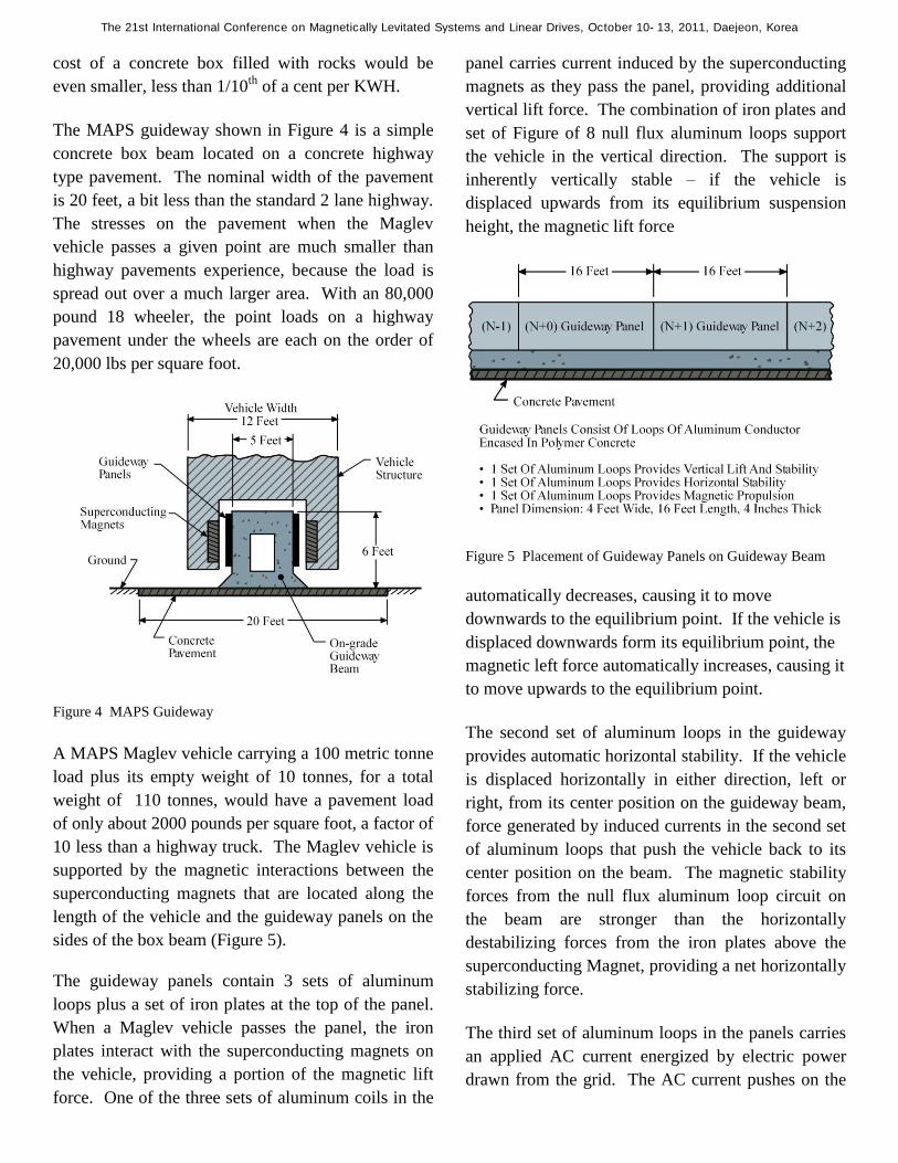
The MAPS guideway shown in Figure 4 is a simple
concrete box beam located on a concrete highway
type pavement. The nominal width of the pavement
is 20 feet, a bit less than the standard 2 lane highway.
The stresses on the pavement when the Maglev
vehicle passes a given point are much smaller than
highway pavements experience, because the load is
spread out over a much larger area. With an 80,000
pound 18 wheeler, the point loads on a highway
pavement under the wheels are each on the order of
20,000 lbs per square foot.
Figure 4 MAPS Guideway
A MAPS Maglev vehicle carrying a 100 metric tonne
load plus its empty weight of 10 tonnes, for a total
weight of 110 tonnes, would have a pavement load
of only about 2000 pounds per square foot, a factor of
10 less than a highway truck. The Maglev vehicle is
supported by the magnetic interactions between the
superconducting magnets that are located along the
length of the vehicle and the guideway panels on the
sides of the box beam (Figure 5).
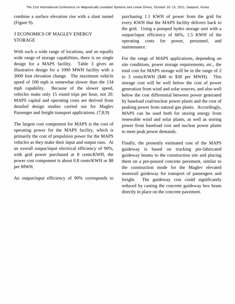
The guideway panels contain 3 sets of aluminum
loops plus a set of iron plates at the top of the panel.
When a Maglev vehicle passes the panel, the iron
plates interact with the superconducting magnets on
the vehicle, providing a portion of the magnetic lift
force. One of the three sets of aluminum coils in the
panel carries current induced by the superconducting
magnets as they pass the panel, providing additional
vertical lift force. The combination of iron plates and
set of Figure of 8 null flux aluminum loops support
the vehicle in the vertical direction. The support is
inherently vertically stable – if the vehicle is
displaced upwards from its equilibrium suspension
height, the magnetic lift force
Figure 5 Placement of Guideway Panels on Guideway Beam
automatically decreases, causing it to move
downwards to the equilibrium point. If the vehicle is
displaced downwards form its equilibrium point, the
magnetic left force automatically increases, causing it
to move upwards to the equilibrium point.
The second set of aluminum loops in the guideway
provides automatic horizontal stability. If the vehicle
is displaced horizontally in either direction, left or
right, from its center position on the guideway beam,
force generated by induced currents in the second set
of aluminum loops that push the vehicle back to its
center position on the beam. The magnetic stability
forces from the null flux aluminum loop circuit on
the beam are stronger than the horizontally
destabilizing forces from the iron plates above the
superconducting Magnet, providing a net horizontally
stabilizing force.
The third set of aluminum loops in the panels carries
an applied AC current energized by electric power
drawn from the grid. The AC current pushes on the
The 21st International Conference on Magnetically Levitated Systems and Linear Drives, October 10-13, 2011, Daejeon, Korea

DC superconducting magnets on the vehicle,
magnetically propelling it along the guideway. The
system can operate either in the motor mode, where
the applied AC current propels the MAPS vehicle
uphill, or downhill in the generator mode, where the
powerful superconducting magnets generate AC
power in the propulsion/generator guideway loop
circuit, which is then fed back to the electric grid, and
braking the vehicles .
There is a DC/AC power conditioning link between
the MAPS power system and the grid. 60 Hertz
power from the grid is rectified to DC and then
inverted to AC power at the proper frequency for the
MAPS System.
As the MAPS vehicle accelerates, the AC frequency
is increased – in effect, the MAPS propulsion system
operates as a Linear Synchronous Motor. As the
MAPS vehicles decelerates, the AC frequency
decreases, and the vehicle operates as a Linear
Synchronous Generator. In the electric sense, MAPS
operates very much like convention synchronous
motors and generators, except that the geometry is
linear, not rotary.
The synchronous nature of the MAPS magnetic
propulsion system is very important. The vehicles
are phase locked into the AC current wave as it
travels along the guideway, with the vehicle speed
controlled by the frequency of the AC wave.
Variations in external force on the vehicle do not
change its speed, only its phase relative to the AC
current wave. In effect the MAPS vehicles travel
much like a surfer on a water wave, with their speed
being the same as that of the wave.
As a consequence, the distance between vehicles
operating on a MAPS guideway will automatically
remain constant, ensuring that collisions cannot
occur. For high propulsion efficiency, the entire
MAPS guideway is not completely energized – only
those sections on which vehicles are currently
operating. The length of each energized block is
approximately 60 meters (200 feet). As a vehicle
leaves an energized block, the propulsion power is
switched into the next block. Similarly, when the
vehicles are running downhill in the generator mode,
the output power is switched off from the block that
the vehicle is leaving, and switched on from the next
block.
Figure 8 illustrates the MAPS energy storage mode,
in which multiple vehicles can operate on the
guideway simultaneously. As each vehicle reaches
the top of the uphill guideway, it unloads it 100 tonne
block into a storage yard. The flat top of each
vehicle has a set of roller bars on which the block
moves. Movement can be achieved either by
powering the roller bars, with their rotation providing
the force required to move the block off of the
vehicle, or by hydraulically tilting the upper surface
of the vehicle, so that the block slides off onto a
conveyer belt, also with roller bars, that moves the
block to a designated location in the storage yard.
The powered roller bar approach appears to be the
most promising system, though the tiltable surface is
also practical.
Figure 8
As an alternative to the roller bar conveyor system to
move the concrete blocks in the storage yard, the
unloading dock can transfer the blocks to the flat top
surface of a wheeled vehicle that moves them to an
appropriate location in the yard, where the block
would sit on a concrete ledge. To receiving the block
The 21st International Conference on Magnetically Levitated Systems and Linear Drives, October 10-13, 2011, Daejeon, Korea

and bring it back to the loading dock for transfer
downhill to generate power, the wheeled vehicle
would simply slide under the sitting block and
hydraulically lift it off its ledge onto the vehicle. The
wheeled vehicle would then quickly move the block
to the loading dock where a roller bar system would
load it onto the Maglev vehicle. The storage yard
would be paved like a highway, with a paved area
equivalent to approximately a mile of 4 lane highway
for a storage capacity of 1,000 megawatt hours.
Maglev vehicles move the 100 tonne blocks
downhill. In the power storage mode, the vehicles
travel in the clockwise direction on the guideway,
while in the energy delivery mode, they travel
counterclockwise. The left side of the guideway
transports the fully loaded vehicles with their 100
tonne blocks both uphill and downhill, requiring a
heavy weight guideway, with the right side of the
guideway transports only the unloaded Maglev
vehicles which are much lighter than the fully loaded
Maglev vehicles, i.e., 10 tonnes versus 110 tonnes.
Multiple vehicles can travel on the MAPS guideway
at the same time, either as individual units, or as
consists of several vehicles coupled together. A
single vehicle can make as many as 20 trips per hour,
depending on the height it raises the 100 tonne block,
e.g., 3000 feet, the angle of the guideway, e.g. 30
degrees, and the maximum speed it travels at, e.g. 60
meters per second (134 mph). The vehicles have to
decelerate as they approach the upper and lower
load/unload points, and accelerate back to maximum
speed after they leave them.
At a maximum speed of 60 meters per second and a
guideway angle of 30 degrees, an individual vehicle
carrying a 100 tonne block is operating at 30
megawatts from the grid if it is storing energy and 30
megawatts to the grid of it is delivering energy. The
power rating can be reduced if desired by operating at
lower maximum speed. Similarly, if the guideway
angle is less than 30 degrees the power rating will be
lower.
Over an 8 hour period, an individual vehicles with 20
round trips per hour and an elevation change of 3000
feet would store 40 MWH. Using multi-vehicle
consists; the amount of energy stored would be much
greater. For example, operating with 25 vehicles in
the multi-vehicle consists, 1000 MWH could be
stored/delivered over an 8 hours period, average
input/output of 125 megawatts. Figure 8 shows an
overall layout of the MAPS facility. There are
switching sections at the top and bottom of the
guideway to sidings where vehicles currently not in
use can be stored. When required to handle increased
power levels, either in the storage mode or the
delivery mode, vehicles can be rapidly switched out
from the sidings to handle the increased power level.
Figure 9. Potential Types of MAPS locations.
MAPS facilities can be sited at a very wide range of
locations, in hilly and flat terrains. In hilly terrains,
the MAPS guideway would ascend on the rising
terrain from a lower elevation to a higher one. On
flat terrain, the MAPS guideway could be located in
slant tunnel (Figure 9) that descended several
thousand feet. Tunnels in hard rock mines descend to
a depth of 9,000 feet or more. In coal mines, with
less stable rock, tunnels descend to depths as much as
3,000 feet. Alternatively, a vertical shaft guideway
could be used, with the blocks stored underground in
tunnels, i.e. “drifts” in mining terms, that lead off
from the vertical shaft. In certain locations where a
greater change in elevation is desired than is
available from local hills, the guideway could
The 21st International Conference on Magnetically Levitated Systems and Linear Drives, October 10-13, 2011, Daejeon, Korea
combine a surface elevation rise with a slant tunnel
(Figure 9).
3 ECONOMICS OF MAGLEV ENERGY
STORAGE
With such a wide range of locations, and an equally
wide range of storage capabilities, there is no single
design for a MAPS facility. Table 3 gives an
illustrative design for a 1000 MWH facility with a
3000 foot elevation change. The maximum vehicle
speed of 100 mph is somewhat slower than the 134
mph capability. Because of the slower speed,
vehicles make only 15 round trips per hour, not 20.
MAPS capital and operating costs are derived from
detailed design studies carried out for Maglev
Passenger and freight transport applications. (7,8,9)
The largest cost component for MAPS is the cost of
operating power for the MAPS facility, which is
primarily the cost of propulsion power for the MAPS
vehicles as they make their input and output runs. At
an overall output/input electrical efficiency of 90%,
with grid power purchased at 8 cents/KWH, the
power cost component is about 0.8 cents/KWH or $8
per MWH.
An output/input efficiency of 90% corresponds to
purchasing 1.1 KWH of power from the grid for
every KWH that the MAPS facility delivers back to
the grid. Using a pumped hydro storage unit with a
output/input efficiency of 66%, 1.5 KWH of the
operating costs for power, personnel, and
maintenance.
For the range of MAPS applications, depending on
site conditions, power storage requirements, etc., the
total cost for MAPS storage will be in the range of 2
to 3 cents/KWH ($40 to $30 per MWH). This
storage cost will be well below the cost of power
generation from wind and solar sources, and also well
below the cost differential between power generated
by baseload coal/nuclear power plants and the cost of
peaking power from natural gas plants. Accordingly,
MAPS can be used both for storing energy from
renewable wind and solar plants, as well as storing
power from baseload cost and nuclear power plants
to meet peak power demands.
Finally, the presently estimated cost of the MAPS
guideway is based on trucking pre-fabricated
guideway beams to the construction site and placing
them on a pre-poured concrete pavement, similar to
the construction mode for the Maglev elevated
monorail guideway for transport of passengers and
freight. The guideway cost could significantly
reduced by casting the concrete guideway box beam
directly in place on the concrete pavement.
The 21st International Conference on Magnetically Levitated Systems and Linear Drives, October 10-13, 2011, Daejeon, Korea
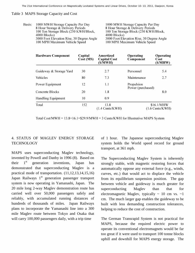
Table 3 MAPS Storage Capacity and Cost
4. STATUS OF MAGLEV ENERGY STORAGE
TECHNOLOGY
MAPS uses superconducting Maglev technology,
invented by Powell and Danby in 1996 (8). Based on
their 1st generation inventions, Japan has
demonstrated that superconducting Maglev is a
practical mode of transportation. (11,12,13,14,15,16)
Japan Railways 1st generation passenger transport
system is now operating in Yamanashi, Japan. The
20 mile long 2-way Maglev demonstration route has
carried well over 50,000 passengers safely and
reliably, with accumulated running distances of
hundreds of thousands of miles. Japan Railways
plans to incorporate the Yamanashi line into a 300
mile Maglev route between Tokyo and Osaka that
will carry 100,000 passengers daily, with a trip time
of 1 hour. The Japanese superconducting Maglev
system holds the World speed record for ground
transport, at 361 mph.
The Superconducting Maglev System is inherently
strongly stable, with magnetic restoring forces that
automatically oppose any external force (e.g., winds,
curves, etc.) that would act to displace the vehicle
from its equilibrium suspension position. The gap
between vehicle and guideway is much greater for
superconducting Maglev than that for
electromagnetic Maglev, typically ~ 10 cm vs. ~1
cm. The much larger gap enables the guideway to be
built with less demanding construction tolerances,
helping to reduce the cost of construction.
The German Transrapid System is not practical for
MAPS, because the required electric power to
operate its conventional electromagnets would be far
too great if it were used to transport 100 tonne blocks
uphill and downhill for MAPS energy storage. The
The 21st International Conference on Magnetically Levitated Systems and Linear Drives, October 10-13, 2011, Daejeon, Korea
superconducting magnets used on superconducting
Maglev vehicles have zero electrical energy losses,
and lift much heavier loads than conventional
electromagnets. There is a small energy requirement
for the refrigeration equipment of the cryogenic
superconducting magnets, but this power requirement
is tiny compared to the input/output power that the
MAPS vehicles handle to move blocks uphill and
downhill.
In recent years, Powell and Danby have developed
the advanced 2nd
generation Maglev 2000 System,
which is more capable and lower in cost than the 1st
generation super conducting Maglev system. The
MAPS system is based on the advanced 2nd
generation Maglev 2000 technology.
First, guideway construction cost for the 2nd
generation Maglev 2000 System is projected to be
only about 25 million dollars per mile, a factor of 2
or more lower than 1st generation systems. To
achieve this, low cost prefabricated monorails are
used for most of the elevated guideway construction.
The prefabricated monorail beams would be mass
produced in factories, with their guideway loop
panels, sensors, electronic equipment, etc. attached to
them at the factory. The beams and piers would then
be transported by truck or rail to the construction site,
where they would be quickly erected on pre-poured
concrete footings or pilings, using conventional
cranes. Guideway cost would be kept low by the use
of conventional box beams for the monorail, which
minimizes the amount of materials required, and
prefabrication, which minimizes expensive field
construction.
The 2nd
generation Maglev 2000 System incorporates
a number of unique new inventions that enable much
greater capability than the 1st generation Japanese and
German Maglev Systems, and are crucial for the
MAPS application. These include:
1. Quadrupole magnets that enable Maglev 2000
vehicles to travel on both monorail and flat surface
guideways.
2. Maglev 2000 vehicles can smoothly transition
back and forth between monorail and flat planar
guideways at high speeds.
3. Maglev 2000 vehicles can electronically switch
from one guideway to another at high speed, without
requiring mechanically moving a long switch section.
Both the Japanese and German 1st generation Maglev
systems require moving long cumbersome sections of
guideway in order to switch from one guideway to
another. Moving the guideway switch takes a long
time, and the vehicle speed must be slow. With
electronic switching operating vehicles can be easily
and greatly transitioned to sidings when power
demand is low, and quickly switched back onto the
main guideway when power demand is high.
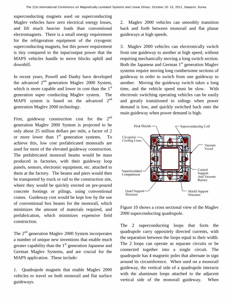
Figure 10 shows a cross sectional view of the Maglev
2000 superconducting quadrupole.
The 2 superconducting loops that form the
quadrupole carry oppositely directed currents, with
the separation between the loops equal to their width.
The 2 loops can operate as separate circuits or be
connected together into a single circuit. The
quadrupole has 4 magnetic poles that alternate in sign
around its circumference. When used on a monorail
guideway, the vertical side of a quadrupole interacts
with the aluminum loops attached to the adjacent
vertical side of the monorail guideway. When
The 21st International Conference on Magnetically Levitated Systems and Linear Drives, October 10-13, 2011, Daejeon, Korea
operating on a planar guideway the bottom face of
the quadrupole magnetically interacts with aluminum
loops located on the guideway beneath the vehicle.
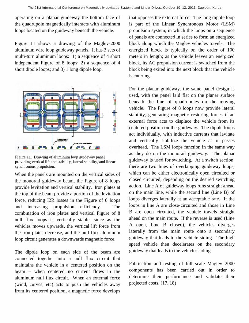
Figure 11 shows a drawing of the Maglev-2000
aluminum wire loop guideway panels. It has 3 sets of
multi-turn aluminum loops: 1) a sequence of 4 short
independent Figure of 8 loops; 2) a sequence of 4
short dipole loops; and 3) 1 long dipole loop.
When the panels are mounted on the vertical sides of
the monorail guideway beam, the Figure of 8 loops
provide levitation and vertical stability. Iron plates at
the top of the beam provide a portion of the levitation
force, reducing I2R losses in the Figure of 8 loops
and increasing propulsion efficiency. The
combination of iron plates and vertical Figure of 8
null flux loops is vertically stable, since as the
vehicles moves upwards, the vertical lift force from
the iron plates decrease, and the null flux aluminum
loop circuit generates a downwards magnetic force.
The dipole loop on each side of the beam are
connected together into a null flux circuit that
maintains the vehicle in a centered position on the
beam – when centered no current flows in the
aluminum null flux circuit. When an external force
(wind, curves, etc) acts to push the vehicles away
from its centered position, a magnetic force develops
that opposes the external force. The long dipole loop
is part of the Linear Synchronous Motor (LSM)
propulsion system, in which the loops on a sequence
of panels are connected in series to form an energized
block along which the Maglev vehicles travels. The
energized block is typically on the order of 100
meters in length; as the vehicle leaves an energized
block, its AC propulsion current is switched from the
block being exited into the next block that the vehicle
is entering.
For the planar guideway, the same panel design is
used, with the panel laid flat on the planar surface
beneath the line of quadrupoles on the moving
vehicle. The Figure of 8 loops now provide lateral
stability, generating magnetic restoring forces if an
external force acts to displace the vehicle from its
centered position on the guideway. The dipole loops
act individually, with inductive currents that levitate
and vertically stabilize the vehicle as it passes
overhead. The LSM loops function in the same way
as they do on the monorail guideway. The planar
guideway is used for switching. At a switch section,
there are two lines of overlapping guideway loops,
which can be either electronically open circuited or
closed circuited, depending on the desired switching
action. Line A of guideway loops runs straight ahead
on the main line, while the second line (Line B) of
loops diverges laterally at an acceptable rate. If the
loops in line A are close-circuited and those in Line
B are open circuited, the vehicle travels straight
ahead on the main route. If the reverse is used (Line
A open, Line B closed), the vehicles diverges
laterally from the main route onto a secondary
guideway that leads to the vehicle siding. The high
speed vehicle then decelerates on the secondary
guideway that leads to the vehicles siding.
Fabrication and testing of full scale Maglev 2000
components has been carried out in order to
determine their performance and validate their
projected costs. (17, 18)
Figure 11. Drawing of aluminum loop guideway panel
providing vertical lift and stability, lateral stability, and linear
synchronous propulsion.
The 21st International Conference on Magnetically Levitated Systems and Linear Drives, October 10-13, 2011, Daejeon, Korea

Figure 12 shows one of the two wound
superconducting loops used for the Maglev-2000
quadrupole. The loop has 600 turns of NbTi
superconducting wire, supplied by SuperCon, Inc. of
Shrewsbury, MA.(14) At the design current of 1000
Amps in the NbTi wire, the Maglev-2000 quadrupole
has a total of 600,000 Amp turns in each of its 2
superconducting (SC) loops. The SC winding is
porous, with small gaps between the NbTi wires to
allow liquid Helium flow to maintain their
temperature at 4.2 K, and to stabilize them against
flux jumps and micro movements.
Figure 13 shows the SC loop enclosed in its stainless
steel jacket. Liquid Helium flows into the jacket at
one end and exits at the end diagonally across from
the entrance providing continuous Helium flow
through the SC winding. Before insertion of the SC
loop into the jacket, it is wrapped with a thin sheet of
high purity, aluminum (5000 residual resistance ratio)
to shield the NbTi superconductor from external
magnetic field fluctuations. After closing the jacket,
a second layer of high purity aluminum is wrapped
around it for additional shielding.
The complete Maglev-2000 cryostat holds 2
superconducting quadrupoles. The magnetic polarity
of the front SC quadrupole is opposite to that of the
rear quadrupole. This allows levitation at lower
speed than if the 2 quadrupoles had the same polarity,
due to less L/R decay of the currents induced in the
aluminum guideway loops. The 2 SC loops are
supported by a graphite-epoxy composite structure
that resists the magnetic forces – due both to the
forces in a loop from its self-current, and to the forces
between the 2 loops – that act on them.
Figure 14 Assembly of Maglev-2000 Superconducting
Quadrupole
Figure 14 shows the SC loops, support structure, and
cooling currents for the Maglev-2000 quadrupole
being assembled in Maglev-2000’s facility on Long
Island. The SC loops have a 10 K thermal shield,
which is cooled by Helium exiting from the jacket
holding the SC loop. The SC quadrupole structure is
then enclosed by an outer layer of multi-layer
insulation (MLI) consisting of multiple alternating
layers of glass fiber and aluminum foil. A second
Figure 12 NbTi Superconductor Loop for Maglev-2000
Quadrupole
Figure 13 NbTI Superconducting Loop Enclosed in Stainless Steel Jacket
The 21st International Conference on Magnetically Levitated Systems and Linear Drives, October 10-13, 2011, Daejeon, Korea
thermal shield encloses the SC quadrupole magnet
assembly, and maintained at ~70 K by the helium
out-flow from the 10 K primary thermal shield.
The completed SC quadrupole was enclosed in a
vacuum cryostat. The quadrupole magnetic levitation
and propulsion forces using DC current in the
aluminum loop guideway assembly beneath the
quadrupole as a stand-in for the induced currents.
The quadrupole was successfully tested to its full
design current of 600,000 Amp turns. The magnetic
forces between the quadrupole and the guideway loop
assembly were measured as a function of vertical
separation and lateral displacement from the centered
position, and longitudinal position in the direction of
movement along the guideway. The measured forces
agreed with 3 D computer analyses.
In the time following the Maglev-2000 quadrupole
tests, high temperature superconductors have become
much more capable, and are being commercially
produced in substantial amounts. Using YBCO high
temperature superconductor wire, it appears very
possible to fabricate Maglev-2000 quadrupoles that
would be much simpler in construction, with much
easier refrigeration requirements. The YBCO
superconductor would operate at 65K with pumped
liquid nitrogen coolant and a much simpler on-board
cryocooler than would be required if NbTI
superconductor at 4.2K were used.
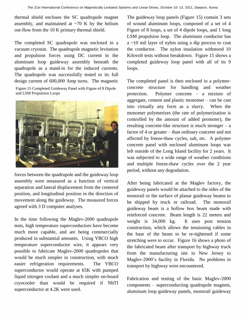
The guideway loop panels (Figure 15) contain 3 sets
of wound aluminum loops, composed of a set of 4
Figure of 8 loops, a set of 4 dipole loops, and 1 long
LSM propulsion loop. The aluminum conductor has
a ~10 mil layer of nylon using a dip process to coat
the conductor. The nylon insulation withstood 10
Kilovolt tests without breakdown. Figure 15 shows a
completed guideway loop panel with all of its 9
loops.
The completed panel is then enclosed in a polymer-
concrete structure for handling and weather
protection. Polymer concrete – a mixture of
aggregate, cement and plastic monomer – can be cast
into virtually any form as a slurry. When the
monomer polymerizes (the rate of polymerization is
controlled by the amount of added promoter), the
resulting concrete-like structure is much stronger – a
factor of 4 or greater – than ordinary concrete and not
affected by freeze-thaw cycles, salt, etc. A polymer
concrete panel with enclosed aluminum loops was
left outside of the Long Island facility for 2 years. It
was subjected to a wide range of weather conditions
and multiple freeze-thaw cycles over the 2 year
period, without any degradation.
After being fabricated at the Maglev factory, the
guideway panels would be attached to the sides of the
monorail or the surface of planar guideway beams to
be shipped by truck or railroad. The monorail
guideway beam is a hollow box beam made with
reinforced concrete. Beam length is 22 meters and
weight is 34,000 kg. It uses post tension
construction, which allows the tensioning cables in
the base of the beam to be re-tightened if some
stretching were to occur. Figure 16 shows a photo of
the fabricated beam after transport by highway truck
from the manufacturing site in New Jersey to
Maglev-2000’s facility in Florida. No problems in
transport by highway were encountered.
Fabrication and testing of the basic Maglev-2000
components – superconducting quadrupole magnets,
aluminum loop guideway panels, monorail guideway
Figure 15 Completed Guideway Panel with Figure of 8 Dipole
and LSM Propulsion Loops
The 21st International Conference on Magnetically Levitated Systems and Linear Drives, October 10-13, 2011, Daejeon, Korea

beam, and vehicle body – have been successfully
carried out.
The MAPS system uses the same components –
Superconducting quadrupoles, monorail guideway
beam (on-grade, rather than elevated, however),
aluminum guideway loop panels for vertical lift,
horizontal & vertical stability, and magnetic
propulsion, and a planar surface electronic switch
between the main guideway and sidings.
The principal difference between the Maglev-2000
transport guideway and the MAPS guideway (Figure
4) is the addition of iron plates in the guideway
panels. The iron plates provide a substantial fraction
of the lift force, without having to induce currents in
the aluminum guideway loops.(16) This reduces I2R
losses in the aluminum loops, increasing propulsion
efficiency. The MAPS suspension is still inherently
stable, because the stability forces from the null flux
aluminum loop circuits are greater than the
destabilizing forces associated with the iron plates, as
analyzed and described in reference (18).
Figure 16 Photo of 72 Foot Long Monorail Guideway Beam
Delivered to Maglev-2000 Facility in Florida From Construction
Site in New Jersey
The MAPS vehicles are much simpler and cheaper
than these used by the Maglev-2000 System to
transport passengers, autos, highway trucks, and
freight containers. They are simple sled type
structures with attached superconducting magnets
and a compact cryogenic refrigeration unit and its
associated plumbing. The powered roller bars on the
upper surface of the sled are similar to units that
operate in many industrial facilities.
Overall, MAPS would use virtually the same
technology as Maglev-2000’s transport system except
that it would be simpler and lower in cost.
Figure 17
The 21st International Conference on Magnetically Levitated Systems and Linear Drives, October 10-13, 2011, Daejeon, Korea

4. US AND WORLD MARKETS FOR
MAGLEV ENERGY STORAGE
The market for MAPS energy storage systems is very
large, both in the US and abroad. Table 4 shows the
annual total electric generation for the US and the
World. US annual generation in 2008 is
approximately 20 percent of the World total. By
2035 AD total World electric generation will almost
double from 2008 values as Asian nations rapidly
industrialize. (19) Replacing expensive electricity
from natural gas peaking plants with mjch less
expensive power from baseload plants that used
MAPS would be a very large market. In the US,
storing 883 million MWH at an average cost of 3
cents/KWH would bring in 28 Billion dollars
annually, sufficient to cover all the costs and pay
back the capital cost of the MAPS facilities over a 30
year period. Assuming that the cost of peaking
power from natural gas plants was 9 cents/KWH
greater than the cost of baseload power, that would
then correspond to a production power savings of 6
cents per KWH using MAPS (+9-3 = 6 cents saved),
a net savings of 56 Billion dollars annually. If the
cost differential of peaking power from natural gas,
compared to baseload power, was greater than 9
cents/KWH, the net savings using MAPS would be
even greater than 56 Billion dollars per year.
Table 4. MAPS Market in US and World
To replace all US power generated from coal and
natural gas power plants, which account for virtually
all of US power generated using fossil fuels, would
cost 88 Billion dollars, based on 3 cents per KWH.
The corresponding cost of CO2 emissions that were
eliminated would be about 40 dollars per ton – a
reasonable price to pay. The elimination of coal and
natural gas plants would be replaced with nuclear,
wind, and solar plants. The corresponding total 2008
World market for MAPS would be about 5 times
greater than in the US, since the total World
generation is approximately 5 times greater than the
US market. The 2008 MAPS revenue for eliminating
World natural gas power generation would be 130
Billion dollars per year; for eliminating coal and
natural gas, the revenues would be 370 Billion dollars
per year. The EIA (Energy Information
Administration) projects that World electrical
generation will double by 2035 as World population
increases and countries become more industrialized.
Coal and natural gas power plants will continue to
dominate electric production, accounting for almost
70% of total power production. It is disheartening
that wind and solar power play such a minor role in
EIA projections for 2035, only about 5% of the total.
To achieve the goal of major reduction in World CO2
emissions, wind and solar will have to play a much
greater role. They can do so, using MAPS storage to
enable wind and solar to reliably deliver large
amounts of power on demand.
The annual revenues shown for MAPS are very large,
and correspond to a major World industry with many
economic and environmental benefits.
The 21st International Conference on Magnetically Levitated Systems and Linear Drives, October 10-13, 2011, Daejeon, Korea

5. PROPOSED DEMONSTRATION PROGRAM
FOR MAGLEV ENERGY STORAGE
The proposed SUMMIT (SUperconducting Maglev
Multi Integrated Testing) facility will demonstrate
the technical and economic feasibility of Maglev
energy storage application [a]. In addition, it will
also demonstrate the technical and economic
feasibility of 2 other Maglev applications: [b) and c)]
a) Efficient, low cost storage of electrical
energy generated by clean, non-polluting
renewable energy sources.
b) Reducing the cost and energy required
for long-distance truck transport, together
with reduction of the pollution and
highway damage that they cause.
c) Low cost, energy efficient long-distance
transport of large amounts of fresh water
to regions with insufficient water
resources, especially the U.S. Southwest.
The three areas are particularly relevant to the
proposed Nevada location of the facility.
Energy Storage: Wind and Solar renewable energy
resources hold great promise in supplying large
amounts of clean energy without the greenhouse gas
emissions that are contributing to global warming, if
a practical, low cost system for energy storage is
developed. Nevada is a very attractive location for
large amounts of wind and solar power.
Truck Transport: The I-15 highway corridor to Las
Vegas is heavily congested, with long distance trucks
being a major contributor to the congestion. They
emit large quantities of pollution, especially diesel
particulates that are very harmful to peoples’ health.
The highway trucks cause extensive damage to
highways, shortening their life, and increasing
maintenance and repair costs. A single 18-wheeler
highway truck causes as much damage as thousands
of autos, according to estimates from transportation
experts.
Water Transport: Finally, Nevada and the Southwest
in general are very short of water. Less water flows
down the Colorado River, Lake Mead is drying up,
and underground water table levels are rapidly
dropping. There is lots of fresh water in the
Columbia River, but pipeline delivery would be far
too expensive for Nevada, Southern California,
Arizona, and New Mexico.
The 2nd
generation Maglev-2000 System can
transport very large tonnages at high speed and low
cost, with very high energy efficiency. It can
transport heavy highway trucks at hundred of mph at
considerably lower cost than driving by highway. A
trucking company using Maglev would only need
1/5th
as many trucks, compared to going by highway.
Similarly, very large quantities of fresh water,
hundreds of millions of gallons of water per day, can
be delivered over distances of hundreds of miles
using Maglev at very low cost – less than 1 dollar per
1000 gallons. Las Vegas could be supplied with
water from the Columbia River; Southern California
could also get water for its crops from the Columbia
River.
The SUMMIT (SUperconducting Maglev Multi
Integrated Testing) facility will demonstrate and
certify Maglev vehicles for the 3 following types of
service:
1. Electrical energy storage
2. Long distance transport of fresh water
3. Long distance high speed transport of
highway trucks.
The 3 types of Maglev vehicles will use a common
design on-grade guideway that can be installed at low
cost. The guideway beam will be poured concrete
monorail box beam positioned on a standard type
concrete highway paved lane that will be
approximately 20 feet wide. The SUMMIT Facility
would test and certify full-scale prototypes of the 3
Maglev vehicles on the on-grade guideway, the
The 21st International Conference on Magnetically Levitated Systems and Linear Drives, October 10-13, 2011, Daejeon, Korea

SUMMIT facility would have 2 phases, as described
below:
Phase 1: Design, Construction of Guideway and
Vehicles, and Initial Testing
The Phase 1 guideway would be approximately 4
miles in length (Figure 17). One end of the guideway
would go uphill at an angle of 20 to 30 degrees, with
an elevation rise in the range of 1500 to 3000 feet,
depending on the location of the facility. The length
of the ascending portion of the guideway would be in
the range of 1/2 to 1 mile, again depending on the
location of the facility, the remaining ~3 to 4 miles of
the guideway would be on relatively flat terrain.
Phase 2: Extended Testing of Vehicles and
Guideway System Developed in Phase 1
Phase 2 would extend the guideway constructed in
Phase 1 and configure it for continuous running. The
~4 mile guideway built in Phase 1 would be a single
line, requiring stopping at each end, and then
accelerating back to speed on the return leg. While
this configuration can demonstrate speed,
acceleration, deceleration, load capability, response
to external forces during the time it takes to travel
from one end of the guideway to the other, it cannot
demonstrate long term reliability and running
performance.
Phase 2 will extend the guideway to a length of ~20
miles with a loop at each end (Figure 28), so that the
Maglev vehicles can run at high speed continuously
along the guideway. Operating at 6000 hours per
year and 200 mph, a Maglev vehicle will accumulate
a total running distance of 1.2 million miles per year,
demonstrating high reliability and the ability to
operate with very low maintenance. Multiple
vehicles will be able to operate on the guideway, e.g.,
several water transport vehicles coupled together as a
single consist, and several highway truck carriers
operating as individual vehicles. The energy storage
guideway would probably operate as a separate unit
to demonstrate better the energy storage and energy
retrieval capabilities of Maglev. The guideway
would incorporate electronic switching sections to
demonstrate the ability of vehicles to switch from the
main line to off-line stations for unloading and
loading operations. This main guideway would also
incorporate elevated monorail guideway sections
enabling vehicles to pass over depressions in the
terrain, roadways, etc. Using electronic switching,
the Maglev vehicles could also transition to a section
of conventional railroad track that had been adapted
for Maglev travel.
Phase 2 would be carried out over a period of 2 years.
At the conclusion of Phase 2, the following will have
been established:
Reliability of long-term operating
performance
Long term maintenance procedures
Ability to operate in all weather conditions
Validation of projected operating costs
After completing Phase 2, the 3 Maglev systems will
be ready for commercial implementation. The
projected cost for the 3 year Phase 1 program is 160
million dollars, including design and construction of
the 4 mile guideway, prototype Maglev vehicles for
the 3 applications, power systems for vehicles
propulsion, operating tests of the prototype vehicles,
and design of the guideway and vehicles for Phase 2
testing, and initiation of construction for Phase 2.
The projected cost for the 2 year Phase 2 program is
170 million dollars, including the completion of the
20 mile guideway and commercially ready Maglev
vehicles for long term testing and the operating tests
themselves.
The 21st International Conference on Magnetically Levitated Systems and Linear Drives, October 10-13, 2011, Daejeon, Korea

6. SUMMARY AND CONCLUSIONS
There is a very large market for low cost, high
efficiency systems that can store large amounts of
electrical energy to be fed to the electrical grid during
peak demand periods. The market is extremely large,
both in the US and the World. Such systems could
store thousands of Megawatt Hours daily generated
from baseload coal and nuclear power plants during
periods of low-grid demand, and feed it back to the
grid during periods of high demand, eliminating the
need for expensive power from natural gas peaking
power plants.
A second major application is to store power from
renewable power sources, particularly wind and
solar. The output from wind turbines and solar
power plants is highly variable –wind generates about
1/3rd
of the time, and is variable and unpredictable,
often not matching grid demand. A third major
application is to supply the grid in the event of
accidents or sabotage that disable power plants and
/or transmission lines to prevent grid collapse.
MAPS (MAglev Power System) is a new way to
store large amounts of electrical energy at very low
cost and very high electrical efficiency for the 3
applications. MAPS can store thousands of
Megawatt Hours at very low cost, 2 to 3 cents per
KWH stored, with an output/input electrical
efficiency of over 90% -- for 100 kilowatt hours
(KWH) of electrical energy fed to a MAPS facility,
over 90 KWH is returned to the grid on demand.
MAPS stores electrical energy using levitated and
magnetically propelled Maglev vehicles to move
heavy masses from a lower elevation to a higher
elevation. The input electric energy to the Maglev
propulsion system, which operates in the motor mode
as it moves mass uphill, is stored as gravitation
potential energy of the mass at its elevated location.
To convert the stored gravitation energy of the mass
back to electric energy and return it to the grid, the
Maglev vehicles moves the mass back to the lower
elevation, with the Maglev propulsion system
operating in the generator mode.
MAPS uses Maglev technology that has been
developed as a practical , very reliable system for
high speed transport of passengers. No
breakthroughs are required – only adapting the
existing Maglev technology for a new application.
MAPS has important advantages compared to other
energy storage systems. Pumped hydro, the most
widely used energy storage system, has a much lower
output/input electrical efficiency. To deliver KWH
back to the grid, it must buy input electrical energy of
1.5 KWH, losing 0.5 KWH in energy inefficiencies
during the storage process. MAPS buys daily 1.1
KWH of electrical enegy, losing just 0.1 KWH,
because of it much greater storage efficiency.
Moreover, pumped hydro has severe environmental
restrictions and problems, and is very limited in
siting. MAPS has far fewer environmental
constraints, and can be sited at a much wider range of
locations. Similarly, MAPS is more efficient than
compressed air storage, and can be sited at a much
wider range of locations.
MAPS can be demonstrated and certified for
commercial use relatively quickly. The proposed
SUMMIT (SUperconducting Maglev Multi
Integrated Testing) program would demonstrate the
operating performance capability of full scale MAPS
vehicles carrying 100 tonne masses uphill for an
elevation increase of several thousand feet.
Efficiency, speed, storage and retrieval capability –
all would be demonstrated. Phase 1 of the SUMMIT
program would take 3 years at a cost of 160 million
dollars. Phase 1 would be followed by Phase 2 in
which would test all of the MAPS system
components, vehicles, guideway, handling
equipment, power conditioning equipment for 2
years, at a cost of 170 million dollars, to demonstrate
system reliability and establish maintenance
requirements.
The 21st International Conference on Magnetically Levitated Systems and Linear Drives, October 10-13, 2011, Daejeon, Korea

REFERENCES
1) “Existing Capacity by Energy Source”, US Energy
Information Administration,
http//:www.eia.gov/eneaf/electricity/epa/epat/1p2.ht
ml
2) “Pumped Storage Hydroelectricity”, Wikipedia,
http//en.wikipedia.org/wiki/pumped-storage,
hydroelectricity
3) “Electric Power Annual 2007: A Summary”; US
Energy Information Administration,
http//:www.eia.gov/bookshelf/brochures/epa/epa.html
4) “Cost of Electricity By Source”, Wikipedia;
http//en.wikipedia.org/wiki/relative_cost_of_electrici
ty_generated_by_different_sources
5) “Energy Storage”, Pew Center for Global Climate
Change,
http://www.pewclimate.org/technology/factsheet/ener
gy storage
6) Electrical Power Storage and Delivery Using
Maglev: The Maglev Power Storage System
(MAPS), J.Powell DPMT-14, November 1, 2000
10) Powell, J. and Danby G.1966. High Speed
Transport by Magnetically Suspended Trains. Paper
66 – WA/RR-5, American Society of Mechanical
Engineers, New York, NY. Also, 1967 A 300 mph
Magnetically Suspended Train. Mech. Eng. 89, 30-
35
11) Powell J. and Danby G. 1969 Magnetically
Suspended Trains for Very High Speed Transport.
Proc. 4th
Intersociety Energy Conversion Engineering
Conference, p.953-63, Washington, DC
12) Powell J. and Danby G. 1970 Dynamically Stable
Cryogenic, Magnetic Suspensions for Vehicles in
Very High Velocity Transport Systems, Recent
Advances in Engineering Science (E.A. C. Eringen)
Gordon & Breach, Vol 5, 159-182
13) Powell J. and Danby G. 1971, Cryogenic
Suspension and Propulsion Systems for 200-2000
mph Ground Transport, Proc. Cryogenic Society of
America Conference on Applications of Cryogenic
Technology, Vol 4, p.299-332.
14) Danby G. and Powell J. 1972, Integrated Systems
for Magnetic Suspension and Propulsions of
Vehicles. Proc. 1972 Applied Superconducting
Conference, p.120-126, Annapolis, Md.
15) Powell J. 1974 A Survey of Large Scale
Applications of Superconductivity, Superconducting
Machines and Devices (Foner.S and Schwartz B, ed)
Plenum Press, p.1-95
16) Danby G., Jackson J., and Powell J, 1974. Force
Calculations for Hybrid (Ferro-Null Flux) Low-Drag
Systems, IEEE Trans on Magnetic, Mag-10, p.443-
446
13) Powell, J. and Danby, G, 1971 The Linear
Synchronous Motor and High Speed Ground
Transport, Proc. 6th
Intersociety Energy Conversion
Engineering Conference, P.118-131, Boston, MA
17) “International Energy Outlook 2010-Highlights”,
US Energy Information Administration;
http//:www.eia.doe.gov/olaf/leo/highlights.html
The 21st International Conference on Magnetically Levitated Systems and Linear Drives, October 10-13, 2011, Daejeon, Korea