large sliding microtome user manual · large sliding microtome user manual . ... operate the device...
TRANSCRIPT

microTec® Laborgeräte GmbH Company for manufacture and distribution of laboratory equipment 1
Mikrotom-XL
Large Sliding Microtome
User Manual

microTec® Laborgeräte GmbH Company for manufacture and distribution of laboratory equipment 2
Table of Contents
Chapter1………………………………………. ..................................................................................................................... 5
1. Basic Instructions………………. ..................................................................................................................... 6
1.1 Significance of the User Manual ............................................................................................................................. 6
1.2 Documents .............................................................................................................................................................. 7
1.2.1 Certificate of Warranty .................................................................................................................................... 7
1.2.2 Commissioning report / acceptance report / instruction report ..................................................................... 8
1.2.3 Repair history ................................................................................................................................................. 10
1.2.4 Declaration of Conformity ............................................................................................................................. 11
1.3 Approved Use ........................................................................................................................................................ 12
1.4 Non-approved Use ................................................................................................................................................ 12
1.5 Warranty and Liability ........................................................................................................................................... 13
1.6 Presentation of Use, Functions, and Operating Process ....................................................................................... 14
1.7 Edition, Issue Date of the User Manual ................................................................................................................ 15
1.8 Copyright ............................................................................................................................................................... 15
1.9 The Manufacturer’s Address ................................................................................................................................. 15
Chapter2………………………………………. ................................................................................................................... 16
2. Basic Safety Instructions…….. .................................................................................................................. 17
2.1Please Observe these Instructions! ....................................................................................................................... 17
2.2 The Operator’s Obligations ................................................................................................................................... 17
2.3 The Personnel’s Obligations .................................................................................................................................. 17
2.4 Potential Hazards when Handling the Device ....................................................................................................... 18
2.5 Explanation of Hazard Symbols ............................................................................................................................. 20
2.6 Useful Instructions from the Manufacturer .......................................................................................................... 21
2.7 Particularly Dangerous Places ............................................................................................................................... 22
2.8 Built-in Safety Features ......................................................................................................................................... 22
2.9 Maintenance and Troubleshooting ....................................................................................................................... 22
2.10 Structural Modifications of the Device ............................................................................................................... 23
2.11 Cleaning and Upkeep .......................................................................................................................................... 23
Chapter3………………………………………. ................................................................................................................... 24
3. Transport and Storage…………. ................................................................................................................. 25
3.1 Dimensions and Weight ........................................................................................................................................ 25
3.2 Instructions for Transport ..................................................................................................................................... 25
3.3 Packing .................................................................................................................................................................. 25
3.4 Acceptance Inspection by Recipient ..................................................................................................................... 25
3.5 Transport Damage Reporting and Required Documentation ............................................................................... 26

microTec® Laborgeräte GmbH Company for manufacture and distribution of laboratory equipment 3
3.6 Ambient Conditions .............................................................................................................................................. 26
Chapter4………………………………………. ................................................................................................................... 27
4. Device Data……………………….. ................................................................................................................... 28
4.1 Name ..................................................................................................................................................................... 28
4.2 Delivery Scope ....................................................................................................................................................... 28
4.3 Ambient Conditions on Operating Site ................................................................................................................. 29
4.4 Technical Data / Performance .............................................................................................................................. 29
Chapter5………………………………………. ................................................................................................................... 30
5. Installation, Assembly, Commissioning .................................................................................................... 31
5.1 Installation ............................................................................................................................................................ 31
5.2 Unpacking/Transport Security Measures ............................................................................................................. 31
5.3 Connecting the Device .......................................................................................................................................... 32
5.4 Assembly of the Accessories ................................................................................................................................. 33
5.4.1 Assembling the Knife Fixture ......................................................................................................................... 33
5.5Device Components, Operating and Display ......................................................................................................... 34
5.6 Instructions re Operating Elements ...................................................................................................................... 35
Chapter6………………………………………. ................................................................................................................... 36
6. Touchscreen, Operating Functions ........................................................................................................... 37
6.1 Turning on the Device ........................................................................................................................................... 37
6.2 Touchscreen .......................................................................................................................................................... 38
6.3 Basic Screen .......................................................................................................................................................... 39
6.4 OM-Setting ............................................................................................................................................................ 40
6.4.1. Tap Setting .................................................................................................................................................... 40
6.4.2. Manual Dial Setting ....................................................................................................................................... 41
6.4.3. Changing Position .......................................................................................................................................... 42
6.5 OM-Automatic ...................................................................................................................................................... 43
6.5.1. Display of Default Values .............................................................................................................................. 44
6.5.2. Display of Actual Values ................................................................................................................................ 45
6.5.3 Selecting the Stroke Type ............................................................................................................................... 45
6.5.4. Cutting Functions .......................................................................................................................................... 49
6.5.5. Preselecting Stop Positions ........................................................................................................................... 51
6.5.6. Trimming ....................................................................................................................................................... 53
6.5.7. Sectioning Way .............................................................................................................................................. 54
6.6 Touchscreen Calibration ....................................................................................................................................... 55
6.7 Screen Cleaning ..................................................................................................................................................... 55
6.8 Info ........................................................................................................................................................................ 56
6.9 Fault Reporting / Troubleshooting ........................................................................................................................ 56

microTec® Laborgeräte GmbH Company for manufacture and distribution of laboratory equipment 4
6.10 Parameters ...................................................................................................................................................... 58
Chapter7………………………………………. ................................................................................................................... 59
7. Operation………………………….. ................................................................................................................... 60
7.1 Sample Fixing ........................................................................................................................................................ 60
7.2 Knife Fitting or Knife Type Changing ..................................................................................................................... 60
7.2.1 Polycut knife Typ 1 + 2 ................................................................................................................................... 61
7.2.2 Universal Knife holder .................................................................................................................................... 63
7.3 Define Default Values /Setting .............................................................................................................................. 64
7.4 Knife Angle Setting ................................................................................................................................................ 65
7.4.1 Polycut Knife holder, Type 1 + 2 .................................................................................................................... 65
7.4.2 Universal Knife holder .................................................................................................................................... 66
7.5 Declination Angle Setting ...................................................................................................................................... 67
7.5.1 Polycut Knife holder (Type 1 + 2) ................................................................................................................... 67
7.5.2 Universal Knife holder .................................................................................................................................... 68
7.6 Section Thickness and Section Number Setting .................................................................................................... 68
7.7 Sectioning Window ............................................................................................................................................... 68
7.8 Sectioning .............................................................................................................................................................. 69
7.9 Select Sectioning Speed ........................................................................................................................................ 71
7.10. Taking off sections ............................................................................................................................................. 72
Chapter8………………………………………. ................................................................................................................... 73
8. Fault Reporting / Troubleshooting ........................................................................................................... 74
Chapter9………………………………………. ................................................................................................................... 75
9. Accessories………………………………. ................................................................................................................... 76
9.1 Accessories to the Knife/Knife holder ................................................................................................................... 76
9.2 Object Fixation and Positioning Accessories ......................................................................................................... 79
9.3 Table accessory ..................................................................................................................................................... 83
Chapter10……………………………………… ................................................................................................................... 84
10. Disposal of waste…………………….. ............................................................................................................. 85
Chapter11…………………………………….. .................................................................................................................. .86
11. Emergency Service, Customer Service .......................................................................................................... 87
11.1 Address................................................................................................................................................................ 87
11.2 Instruction for Emergency and Customer Services ............................................................................................. 87
Chapter12…………………………………….. ................................................................................................................... 88
12. List of Figures/Illustrations………… ........................................................................................................... 89
Chapter13…………………………………….. .................................................................................................................. .90
13. Notes………………………………………. ............................................................................................................. 91
microTec® Laborgeräte GmbH Company for manufacture and distribution of laboratory equipment 5
Chapter1
Basic Instructions
1.Basic Instructions ............................................................................................... 6
1.1 Significance of the User Manual ............................................................................ 6
1.2 Documents ............................................................................................................. 7
1.2.1 Certificate of Warranty. ...................................................................................... 7
1.2.2 Commissioning report / acceptance report / instruction report. ....................... 8
1.2.3 Repair history. ................................................................................................... 10
1.2.4 Declaration of Conformity. ................................................................................ 11
1.3 Approved Use ....................................................................................................... 12
1.4 Non-approved Use ............................................................................................... 12
1.5 Warranty and Liability .......................................................................................... 13
1.6 Presentation of Use, Functions, and Operating Process ...................................... 14
1.7 Edition, Issue Date of the User Manual................................................................ 15
1.8 Copyright .............................................................................................................. 15
1.9 The Manufacturer’s Address ................................................................................ 15

microTec® Laborgeräte GmbH Company for manufacture and distribution of laboratory equipment 6
1. Basic Instructions
1.1 Significance of the User Manual
Dear Customers,
Please read the User Manual thoroughly before the commissioning of the appliance and
make sure that you become acquainted with the functions and user elements, as it is
imperative to ensure proper handling of the device.
Please compare the machine number with the number on the microTec type label of your
device.
Inquiries and service can be simplified, if you always quote the machine number.
microTec– machine number: -
microTec Laborgeräte GmbH
Rudolf-Diesel-Str. 47 69190 Walldorf, Germany Phone: + 49 (0) 6227 / 8222-0 Fax: + 49 (0) 6227 / 8222-30 [email protected] www.micro-tec.de

microTec® Laborgeräte GmbH Company for manufacture and distribution of laboratory equipment 7
1.2 Documents
1.2.1 Certificate of Warranty
Certificate of Warranty
microTec Laborgeräte GmbH hereby grants the legal guarantee in accordance with german law.
The warranty period begins after commissioning and instruction of the device.
The dealer must pass on a commissioning record, acceptance report and the warranty certificate to the
manufacturer. Within the guarantee, microTec Laborgeräte GmbH provides the spare parts free
of charge.
Customer: __________________________________________________________________
Contact person: _____________________________________________________________
Street / No.: ________________________________________________________________
Town / zip code: _____________________________________________________________
Model: _____________________________________________________________________
Serial number: _______________________________________________________________
Distributor: __________________________________________________________________
In order to assert warranty claims, the microtome must be displayed at the authorized dealer where the
device was purchased. The original invoice with the date and the warranty certificate must be enclosed.
Warranty and liability claims for personal injury or material damage are excluded if these are attributable to
one or more of the following causes:
Non-intended use of the device
Incorrect installation, commissioning, operation and maintance of the device
Operate the device in the case of defective, improperly installed or non-functional safety and protective
devices
Do not pay attention to the instructions in the operating instructions regarding transport, storage,
installation, commissioning, operation, maintenance and setting up of the device
Unauthorized structural modification of pneumatic, electrical and mechanical parts
Long-term monitoring of machine parts subject to wear
Improper repairs performed
Disasters caused by contaminant and force majeure
microTec® Laborgeräte GmbH Company for manufacture and distribution of laboratory equipment 8
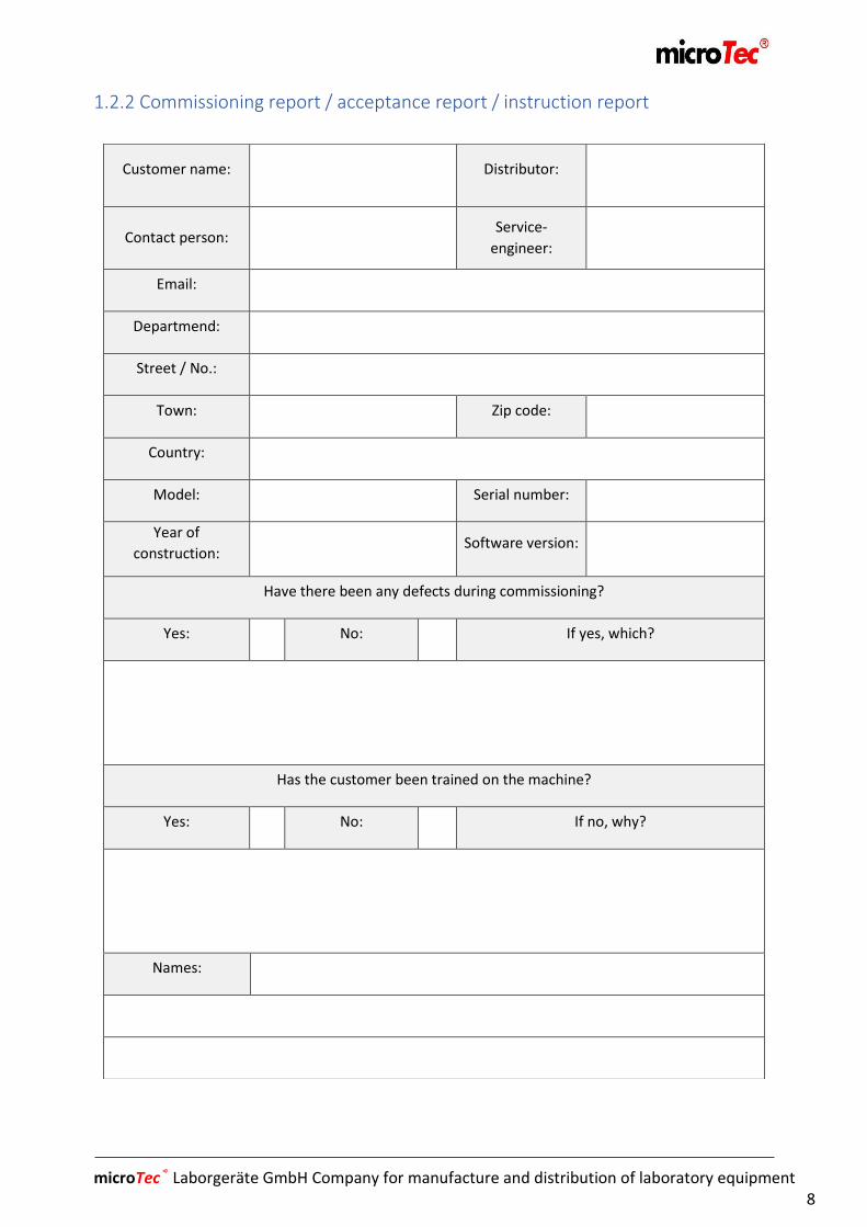
1.2.2 Commissioning report / acceptance report / instruction report
Customer name: Distributor:
Contact person: Service-
engineer:
Email:
Departmend:
Street / No.:
Town: Zip code:
Country:
Model: Serial number:
Year of
construction: Software version:
Have there been any defects during commissioning?
Yes: No: If yes, which?
Has the customer been trained on the machine?
Yes: No: If no, why?
Names:

microTec® Laborgeräte GmbH Company for manufacture and distribution of laboratory equipment 9
Were there missing parts?
Yes: No: If yes, which?
Were there problems with the installation?
Yes: No: If no, why?
Notes:
The microtome has been installed by an proffesional:
Date / Signature / Stamp
Customer:
Date / Signature / Stamp
Service- engineer:

microTec® Laborgeräte GmbH Company for manufacture and distribution of laboratory equipment 10
1.2.3 Repair history
Model: Machine – No.:
Problem: Task: Responsible: Date: Status:

microTec® Laborgeräte GmbH Company for manufacture and distribution of laboratory equipment 11
1.2.4 Declaration of Conformity
EU Declaration of Conformity
Pursuant to EC Machine Directive 2006/42/EC, Annex II, 1.A
Manufacturer: microTec Laborgeräte GmbH Rudolf-Diesel-Str. 47 D-69190 Walldorf, Germany
Product:
Serial Number:
Person in the Community duly authorized to compile the relevant technical documentation: Walter Ganter – microTec Laborgeräte GmbH Walldorf, 11.11.2015
Place, Date Walter Ganter, managing director
It is declared, bearing sole responsibility, that the product meets the abovenamed Directive and the
subsequent harmonizing standards applied.
2006/42 /EC:2006-05-17 2006/42 /EC: EU Machine Directive 2006/42 /EC 2006/95 /EC: (Low Voltage Directive) Directive of the European Parliament and Council of 12 December 2006 on the
approximation of the Member States‘ laws concerning electrical equipment designated for use within certain voltage limits (Codified Version) (1)
2004/108 /EC: (Electromagnetic Compatibility) Directive of the European Parliament and Council of 15 December 2004 on the approximation of the Member States’ laws concerning electromagnetic compatibility and repealing Directive 89/336/EEC
2006/42 /EC: (Machine Directive) Directive 2006/42/EC of the European Parliament and Council of 17 May 2006 on machines and amending Directive 95/16 /EC (New Version) (1)
References to harmonized standards applied:
EN ISO 13849-1:2008 Machinery Safety – Safety-relevant control components - Part 1: General Design Principles (ISO 138491:2006)
EN 62061:2005 Machinery Safety – Functional safety of safety-relevant electrical, electronic, and programmable electronic control systems
EN ISO 13857:2008 Machinery Safety – Safety distances to prevent hazardous zones being reached by upper and lower limbs (ISO 13857:2008)
EN 60204-1:2006-06 Machinery Safety – Electrical Equipment of Machines - Part 1: General Requirements EN ISO 14121-1:2007 Machinery Safety – Risk Assessment - Part 1: Guiding Principles (ISO 14121-1:2007)
Apart from the above, company standards compliant with DIN EN ISO 9001:2008 have been applied.
Mikrotom-XL / Microtome for Cutting Large and Hard Slices
-
microTec® Laborgeräte GmbH Company for manufacture and distribution of laboratory equipment 12
1.3 Approved Use
Mikrotom-XL is an electronically operated large microtome slicer designated for work in
paraffin sectioning, hard sectioning, and material sciences in the fields of biology,
medicine, and industry.
The sectioning range can be set up between 0 – 1.000 µm in 1 µm steps.
The user-friendly disposable blades and universal knife holder with integrated knife guard
ensure problem-free clamping and adjusting of the knives.
Mikrotom-XL is fitted with an integrated sectioning counter that shows the number of
performed sections on the operator’s display panel.
In order to prevent damage to the knife or the sample, Mikrotom-XL is provided with a
knife retraction function during the test, which may be set liberally between 0 – 1.000µm.
Three-stage trimming function (10µm, 20µm and 30µm) is another built-in function.
The sectioning range is liberally adjustable and can be limited by a teach function (reset).
The device can be controlled optionally in single stroke, continuous stroke, touch stroke,
or pre-dial stroke mode using the control unit or foot switch.
A two-stage manual method with the knife, as well as a one-stage method with the
sample is possible.
1.4 Non-approved Use
Mikrotom-XL is designed and built in accordance with present-day technology and
recognized regulations of technical safety. Nevertheless, personal injury to the user or
third parties, or impairment to the device, software, or other material values may still
occur. Therefore, the device is only to be used:
for designated purposes
in a technically safe and perfect condition

microTec® Laborgeräte GmbH Company for manufacture and distribution of laboratory equipment 13
1.5 Warranty and Liability
The company microTec GmbH confirms that the device has been carefully tested and
reexamined. The conformity of the published data was verified prior to delivery of the
device.
The device is classified as Med GV Class 4. Compliance with current regulations is ensured.
This microTec product is covered against any defects of material or workmanship under a
warranty for 12 months following purchase, free of charge. During the warranty period,
defective parts will be repaired or replaced. Any further claims are precluded. Defects
caused by a third-party intervention are not covered by the warranty.
In order to file a valid warranty claim, Mikrotom-XL must be presented to the authorized
dealer, where the device was bought, along with the original receipt, dated, the purchase
note, and the Warranty Certificate.
In general, all claims are subject to our General Purchase and Delivery Conditions that will
be available to the operator at the latest upon signature of the purchase contract. In
cases of personal or material injury, warranty and liability claims are precluded, if one or
multiple causes of the injury/injuries is/are consequential to:
unapproved use of the device!
Unprofessional installation, commissioning, operation, and/or maintenance of the device;
operation of the device using defective, improperly installed, or dysfunctional safety and/or protective facilities;
non-observance of the instructions in the User Manual concerning transport, storage, installation, commissioning, operation, maintenance, and setup of the device;
unauthorized structural modification of pneumatic, electrical, and/or mechanical parts;
inadequate monitoring of the machine components that are prone to wearing;
improperly done repairs;
disasters caused by the impact of alien particles and/or vis major.

microTec® Laborgeräte GmbH Company for manufacture and distribution of laboratory equipment 14
1.6 Presentation of Use, Functions, and Operating Process
Designated Use Mikrotom-XL is a fully automated device designated for all types of work using paraffin
and hard-sectioning technology and material sciences in the fields of biology, medicine,
and industry.
The Functions and Operating Process Mikrotom-XL operates on the principle of rotary motion of an engine driven by belts that
transpose the motion into vertical sample sectioning. The specimen are sectioned by
regrindable knives (sharpening) or disposable blades adapted to and held by various
clamps and holders.
The sectioning motion is used for sectioning the object. If selecting the continuous mode,
the section is done up to a pre-defined end point, where knife retraction follows and
drives the knife by a selected value upwards. Thereupon, the knife returns to the starting
point in front. This is where the thickness of the specimen is selected and the sectioning
motion restarts.
In the single-stroke mode, the object sectioning stops at the rear or front point, as
selected.
The single-stroke, continuous-stroke, as well as the touch-stroke may be controlled both
from the operator panel or the foot switch.
The device has a three-stage trimming function, which facilitates quick approximation of
the sample.
In order to be able to accommodate different types of objects, the device is provided with
a multifunction object clamping system. Object positioning allows simple alignment to the
sectioning plane possible.
The different knife holders ensure a problem-free fitting with various types of knives and
proper use-specific setting.

microTec® Laborgeräte GmbH Company for manufacture and distribution of laboratory equipment 15
1.7 Edition, Issue Date of the User Manual
Edition: Version 001.16 Date of Issue: 13.06.2016
1.8 Copyright
Copyright: microTec Laborgeräte GmbH
The copyright to this User Manual remains the property of microTec Laborgeräte GmbH.
The User Manual is intended to be used solely by the operator and its personnel.
It contains regulations and instructions that may not be, completely or partly:
- duplicated,
- distributed,
- or otherwise disclosed to other parties.
Violations could be legally prosecuted.
1.9 The Manufacturer’s Address
microTec Laborgeräte GmbH
Rudolf-Diesel-Str. 47 69190 Walldorf, Germany Phone: + 49 (0) 6227 / 8222-0 Fax: + 49 (0) 6227 / 8222-30 [email protected] www.micro-tec.de
microTec® Laborgeräte GmbH Company for manufacture and distribution of laboratory equipment 16
Chapter2
Basic Safety Instructions
2. Basic Safety Instructions .................................................................................. 17
2.1 Please Observe these Instructions! ................................................................... 17
2.2 The Operator’s Obligations ................................................................................ 17
2.3 The Personnel’s Obligations .............................................................................. 17
2.4 Potential Hazards when Handling the Device ................................................... 18
2.5 Explanation of Hazard Symbols ......................................................................... 20
2.6 Useful Instructions from the Manufacturer ..................................................... 21
2.7 Particularly Dangerous Places ........................................................................... 22
2.8 Built-in Safety Features ...................................................................................... 22
2.9 Maintenance and Troubleshooting ................................................................... 22
2.10 Structural Modifications of the Device ............................................................ 23
2.11 Cleaning and Upkeep ....................................................................................... 23

microTec® Laborgeräte GmbH Company for manufacture and distribution of laboratory equipment 17
2. Basic Safety Instructions
2.1Please Observe these Instructions!
A basic prerequisite to safe handling and trouble-free operation of the device is the
knowledge of the basic safety instructions and safety regulations.
This User Manual contains important instructions how to operate the device safely.
This User Manual, particularly the safety instructions in it, are to be observed by all persons
who work with the device.
Moreover, it is imperative to follow all the locally applicable rules and regulations for
accident prevention.
2.2 The Operator’s Obligations
The Operator undertakes to entrust the operation of the device exclusively to persons who
are acquainted with the basic regulations of work safety and accident prevention,
and instructed about the handling of the device;
have read and understood the chapter on safety and the warnings in this User
Manual;
have been taught to approach work processes conscientiously.
2.3 The Personnel’s Obligations
All persons assigned to work with the device, before they start to work, assume the
following obligation:
to observe the basic work safety and accident prevention regulations;
to make sure that they read and comprehend the chapter on safety and the
warnings in this User Manual.
microTec® Laborgeräte GmbH Company for manufacture and distribution of laboratory equipment 18
2.4 Potential Hazards when Handling the Device
Caution!
The following safety measures must be observed
whenever using the device. Failure to follow these
precautions would constitute a violation of recognized
technical rules as well as appropriate use of the device.
microTec Laborgeräte GmbH precludes liability for any
infringements or violations of these precautions.
Danger of Injury
When setting up the knife and object, the worker should
be wearing finger protection as well as gloves as
protection against cuts, in order to minimize the risk of
injury by the knife or blade.
Always fasten the object first, then set the knife in to the
knife holder.
Before changing the clamping system, always take out the
knife/blade first. Knives that are not being used should
always be properly safeguarded in a knife box. Never try
to catch a falling knife in midair. Be careful during the
sectioning process and while taking off the section.
Risk of an Infection
When working with infectious material, always wear
proper protection and apply disinfection measures.

microTec® Laborgeräte GmbH Company for manufacture and distribution of laboratory equipment 19
Risk of Radiation
When working with radioactive materials or objects,
always observe the relevant anti-radiation regulations.
Risk of Splinters
When sectioning brittle samples, there exists potential
danger of splinters – therefore, always wear protective
glasses.
Risk of Magnetic Fields
Persons wearing a pacemaker may not perform work where
a magnet is used as a means of fastening.
General Safety Instructions and Warnings
During the sectioning processes, make sure that no liquid
penetrates into the device.
Whenever the sectioning process is interrupted, close the
finger guard.
During cleaning and maintenance work, the device may
only be opened by authorized personnel.
Before cleaning, the device must be turned off and
disconnected from power. (Touchscreen may be cleaned
while turned on).
The operator panel must be turned off before cleaning.
Do not clean with solvents or abrasive cleaners.
Use appropriate cleaning detergents for the operator’s
panel and non-lacquered parts. Use only slightly moistened
cloth for cleaning.

microTec® Laborgeräte GmbH Company for manufacture and distribution of laboratory equipment 20
2.5 Explanation of Hazard Symbols
Signalword
Pictogram
- Danger
- Warning
- Caution
- Note
- Important!
- Information

microTec® Laborgeräte GmbH Company for manufacture and distribution of laboratory equipment 21
2.6 Useful Instructions from the Manufacturer
Object Preparation
When preparing objects for sectioning, care must be taken to select the correct
embedding medium, as well as the time of fixation and infiltration.
Object Temperature
As a rule, sectioning is done at room temperature (frozen materials excepting). Paraffin
softens at higher temperature, therefore avoid working in direct sunlight or near any
source of heat.
Instructions for Setting the Knife
Depending on the facet cut, angle setting of approx.10-15° is recommended. When using
a sharpened knife, the height of the knife must be adjusted accordingly.
Lever and Clamping Screws
All lever and clamping screws on the knife fixture and object position must be firmly
tightened.
Sectioning Speed
Note: «The harder the material, the slower the sectioning speed».
Starting to Section
Be careful when approaching the knife and/or object.
microTec® Laborgeräte GmbH Company for manufacture and distribution of laboratory equipment 22
2.7 Particularly Dangerous Places
CAUTION !
- Microtome knives are very sharp.
After ending or interrupting work, even if for a
short time, it is imperative to apply the knife
guard or take the knife out and put away safely.
- The device is to be placed in a safe place.
Mikrotom-XL can roll away – therefore, the brakes must be activated at all
times, as they lift Mikrotom-XL and take the weight off the rollers, so that
position shifting is not possible.
2.8 Built-in Safety Features
- Emergency button on the operator’s panel
- Emergency button on the foot switch, integrated
- Finger guard over the knife
- Overloading control of the engine
2.9 Maintenance and Troubleshooting
Maintenance
In order to ensure the quality of cutting and safe functionality of the device, a routine
maintenance should be performed annually. Maintenance tasks may only be carried out
by trained service technicians.
Maintenance Contract
microTec offers a maintenance contract which guarantees that your device will be in
perfect condition.
Troubleshooting
Malfunctions affecting safety are to be rectified and/or reported immediately.
microTec® Laborgeräte GmbH Company for manufacture and distribution of laboratory equipment 23
2.10 Structural Modifications of the Device
- No modifications, additions, or reconstructions may be made without the
manufacturer’s permission
- All modification measures require a confirmation/release of microTec in writing.
- Machine parts that are not in perfect condition are to be replaced immediately.
- Only original spare parts and consumables may be used.
In the event that non-original parts are used, it cannot be guaranteed that they meet the relevant manufacturing and safety requirements.
2.11 Cleaning and Upkeep
Cleaning
Depending on the degree of contamination and frequency of use, it is recommended that
the device be cleaned regularly using mild household detergents. Aggressive cleaning
materials or solvents may not be used, as they could damage the surface of lacquered or
plastic parts. It is advised to move the device into the changing position for cleaning.
Always take the knife out and put it in the knife box, before
starting the cleaning process.
Caution!
Never put the knife on the desk with the cutting edge up. The
contact surfaces as well as the knife guiding carriers should be
cleaned particularly thoroughly.
Upkeep
When the device is not being used, move the cutter into the „changing“ position and close
the cover that is enclosed in the delivery, then use the main switch to turn the device off.

microTec® Laborgeräte GmbH Company for manufacture and distribution of laboratory equipment 24
Chapter3
Transport and Storage
3. Transport and Storage ..................................................................................... 25
3.1 Dimensions and Weight ..................................................................................... 25
3.2 Instructions for Transport .................................................................................. 25
3.3 Packing ............................................................................................................... 25
3.4 Acceptance Inspection by Recipient .................................................................. 25
3.5 Transport Damage Reporting and Required Documentation ........................... 26
3.6 Ambient Conditions ........................................................................................... 26
microTec® Laborgeräte GmbH Company for manufacture and distribution of laboratory equipment 25
3. Transport and Storage
3.1 Dimensions and Weight
Dimensions in mm:
Microtome (HxWxL): ................................................................................ 400x480x810
Control unit/panel (HxWxL):……………………..…….…150x470x400 plus telescope mounting
Microtome main frame (HxWxL): ........................................ .……………….. 995x665x1175
Required minimum space for the Microtome (HxWxL):…………….…….1.500x2.000x1.600
Weight in kg:
Weight (without accessories):…………………………………………………………………………..550 kg
3.2 Instructions for Transport
Remove all knives, the knife box, object carrier, and objects from Mikrotom-XL. Bring the
operator’s panel centrally over the microtome to a convenient transport situation. When
lifting the microtome box, hold it only by the specially marked points for lifting.
3.3 Packing
The microtome is delivered in a specially lined wooden box. Mikrotom-XL may be only be put
into operation after 24 hours following delivery.
3.4 Acceptance Inspection by Recipient
Check, whether all the parts ordered are contained in the transport box. Check the transport
box itself and the microtome for any transport damage.

microTec® Laborgeräte GmbH Company for manufacture and distribution of laboratory equipment 26
3.5 Transport Damage Reporting and Required Documentation
Any and all transport damage is to be reported to the manufacturer immediately and the
transport company notified.
3.6 Ambient Conditions
- Storage temperature -20°C to + 50°C
- Not to be stored in open areas; protect from rain or moisture.
microTec® Laborgeräte GmbH Company for manufacture and distribution of laboratory equipment 27
Chapter4
Device Data
4. Device Data .................................................................................................... 28
4.1 Name.................................................................................................................. 28
4.2 Delivery Scope ................................................................................................... 28
4.3 Ambient Conditions on Operating Site .............................................................. 29
4.4 Technical Data / Performance ........................................................................... 29

microTec® Laborgeräte GmbH Company for manufacture and distribution of laboratory equipment 28
4. Device Data
4.1 Name
Mikrotom-XL
4.2 Delivery Scope
as per Contract

microTec® Laborgeräte GmbH Company for manufacture and distribution of laboratory equipment 29
4.3 Ambient Conditions on Operating Site
- 18 °C to + 35°C
- Relative air humidity up to 60%, maximum, no condensation.
4.4 Technical Data / Performance
Mikrotom-XL
Sectioning thickness range: 0µm to 1.000µm, adjustable by µm Total sample feed: max. 350 mm Total vertical stroke of the knife: max. 70 mm Knife retraction (during sample processing): liberally adjustable 0 µm to 1.000 µm Wide angle setting: 0° to 30° Knife declination: liberally adjustable 0° to 80° (with adjustable knife fixture) Maximum sample size (LxWxH): 300x200x70 mm Sample orientation on X/Y axis: 5°
Sample orientation on Z axis: 360° (by means of a magnet clamp) Cutting speed: 1 mm/s to 125 mm/s, adjustable by 1mm Processing speed: 1 mm/s to 125 mm/s, adjustable by 1mm Cutting window: liberally adjustable Manual mode of the knife: in two stage Manual mode of the sample: in one stage Electrical Connections Nominal voltage: 400 V Nominal frequency: 50 Hz Power: 1,5 kW Nominal current: 6,3 A Total power consumption: max. 1,500 VA Fuse: 16A
(Technical data subject to change without notice)
microTec® Laborgeräte GmbH Company for manufacture and distribution of laboratory equipment 30
Chapter5
Installation, Assembly, Commissioning
5. Installation, Assembly,Commissioning ............................................................. 31
5.1 Installation ......................................................................................................... 31
5.2 Unpacking/Transport Security ........................................................................... 31
5.3 Connecting ......................................................................................................... 32
5.4 Assembly of Accessories .................................................................................... 33
5.4.1Knife holder Assembly ..................................................................................... 33
5.5 Device Components, Operating and Display Elements ..................................... 34
5.6 Instruction to Operating Elements .................................................................... 35

microTec® Laborgeräte GmbH Company for manufacture and distribution of laboratory equipment 31
5. Installation, Assembly, Commissioning
5.1 Installation
Protect the device from: - Sources of heat, such as heating fans or hot-air fans - Extremely low temperatures - Direct sunlight - Very dusty environment - Moisture or rain - Mechanical vibrations or bumping - Devices containing magnets or producing magnetic fields Installation Conditions: - Space for placing the microtome and operator’s panel of at least 1.400 x 2.000 x 1.600 mm - At least 150mm free space around the device for air circulation - Virtually vibration-free floor - Room temperature steadily between + 18°C to + 35°C - Relative air humidity of up to 60%, maximum, condensation-free.
5.2 Unpacking/Transport Security Measures
Lift the box solely by the points specially marked for lifting. Open the transport box and
remove all transport security elements, adhesive tapes, and protective foil. Prop the
device on the rollers and roll it carefully down the ramp.
CAUTION! The device is very heavy. There is a risk of injury or crushing, if the device is being rolled without the possibility of braking.
microTec® Laborgeräte GmbH Company for manufacture and distribution of laboratory equipment 32
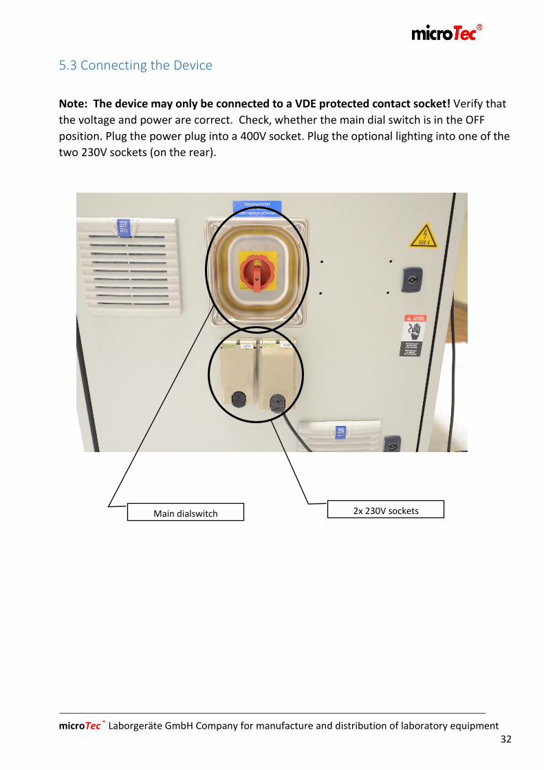
2x 230V sockets Main dialswitch
5.3 Connecting the Device
Note: The device may only be connected to a VDE protected contact socket! Verify that
the voltage and power are correct. Check, whether the main dial switch is in the OFF
position. Plug the power plug into a 400V socket. Plug the optional lighting into one of the
two 230V sockets (on the rear).
microTec® Laborgeräte GmbH Company for manufacture and distribution of laboratory equipment 33
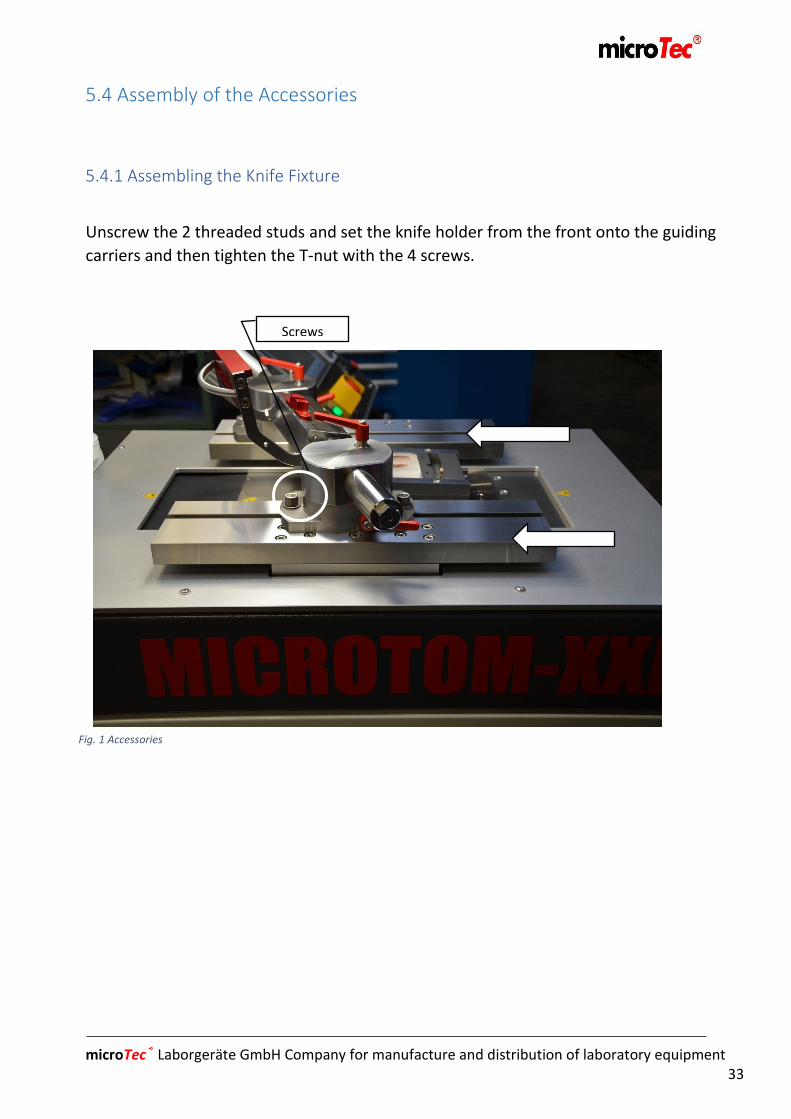
Screws
Fig. 1 Accessories
5.4 Assembly of the Accessories
5.4.1 Assembling the Knife Fixture
Unscrew the 2 threaded studs and set the knife holder from the front onto the guiding
carriers and then tighten the T-nut with the 4 screws.

microTec® Laborgeräte GmbH Company for manufacture and distribution of laboratory equipment 34
Fig. 2 Mikrotom-XL
5.5Device Components, Operating and Display
1. Mikrotom-XL
1.1 Sample carrier
1.2 Knife carrier/Guiding
1.3 Object positioning
1.4 Lateral knife adjustment
1.5 Knife holder
1.6 Finger guard
2. Optional magnifying glass w/lighting
3. Operator’s panel
3.1 Touchscreen
3.2 Manual knife carrier dial
3.3 Manual object carrier dial
3.4 Potentiometer
sectioning speed
3.5 Emergency button
3.6 Ready-for-operation lights
4. Foot switch
5. Heavy-duty rollers
1.
3.6
3.5
3.4
3.3
3.2
3.1
3.
2.
1.6
1.5
1.4
1.3
5.
4.
1.2
1.1

microTec® Laborgeräte GmbH Company for manufacture and distribution of laboratory equipment 35
Fig. 3 Foot switch Fig. 4 Potentiometer & manual dials
3.2 3.4 Potentiometer
5.6 Instructions re Operating Elements
- Ad 3.2.and 3.3. manual dials: The manual dials are only active in the window dial
(6.4.2), where they can be switched to the different time carriers of the grid.
- Ad 3.4 potentiometer: The potentiometer is used for adjusting the cutting speed.
When the potentiometer is set at Zero, the object carrier cannot be moved, until the
potentiometer is turned to the desired value.
- Ad 4. foot switch. The foot switch can be activated/deactivated using touchscreen,
where OM-Automatic and all stroke types may be started. Firm pressure on the foot
switch will activate the emergency function and the reason for problem reporting is
to be acknowledged (6.9). Before acknowledgement, it is necessary to press the blue
button on the foot switch.
- Ad 5. heavy-duty rollers: The heavy-duty rollers are used for moving the device.
During the cutting process and after positioning the device in its location, the built-in
brakes must be used to prevent the device from rolling and the support footing set as
described in in Chapter 2.7.

microTec® Laborgeräte GmbH Company for manufacture and distribution of laboratory equipment 36
Chapter6
Touchscreen, Operating Functions
6. Touchscreen, Operating Functions ................................................................... 37
6.1 Turning on the Device ........................................................................................ 37
6.2 Touchscreen ...................................................................................................... 38
6.3 Basic Screen ....................................................................................................... 39
6.4 OM-Setting ......................................................................................................... 40
6.4.1. Setting Tapping .......................................................................................... 40
6.4.2. Manual Dial Setting ................................................................................... 41
6.4.3. Changing Position ..................................................................................... 42
6.5 OM-Automatic ................................................................................................... 43
6.5.1. Displsy of Default Values .......................................................................... 44
6.5.2. Display of Actual Values ............................................................................ 45
6.5.3 Selecting Stroke Type ................................................................................. 46
6.5.4. Cutting-related Functions .......................................................................... 49
6.5.5. Setting up Stop Positions ........................................................................... 51
6.5.6. Trimming .................................................................................................... 53
6.5.7. Sectioning Window .................................................................................... 54
6.6 Touchscreen Calibration .................................................................................... 55
6.7 Display Cleaning ................................................................................................. 55
6.8 Info ..................................................................................................................... 56
6.9 Troubleshooting ................................................................................................ 57
6.10 Parameters ...................................................................................................... 58

microTec® Laborgeräte GmbH Company for manufacture and distribution of laboratory equipment 37
Fig. 5 Basic screen / Start screen
6. Touchscreen, Operating Functions
6.1 Turning on the Device
Turn the main switch to “I ON” and wait until the screen below appears (Fig. 5).The light
below (3.6) turns green, thus signalizing that the device is ready for operation. After
booting/startup, the fault reporting field turns red, the reason being that the SPS/control
starts faster than the converter. After pressing F7 (not on Touchscreen), you come the
fault reporting window (Fig. 6).
microTec® Laborgeräte GmbH Company for manufacture and distribution of laboratory equipment 38
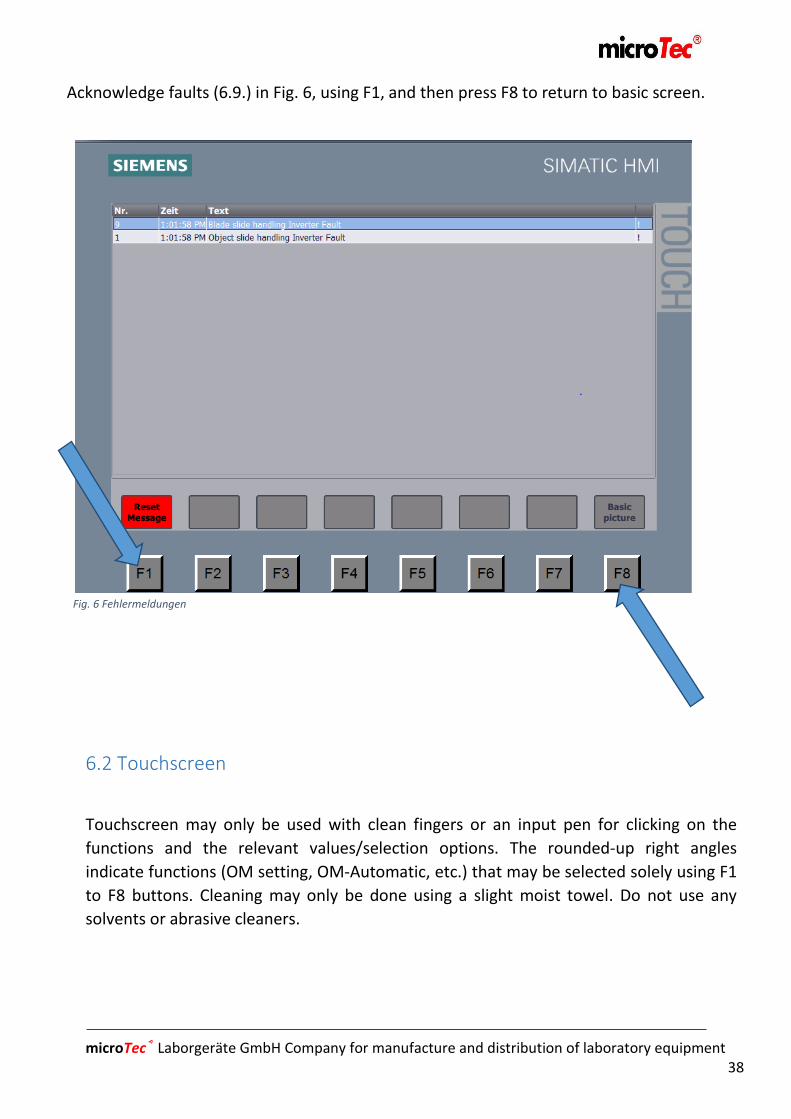
Fig. 6 Fehlermeldungen
Acknowledge faults (6.9.) in Fig. 6, using F1, and then press F8 to return to basic screen.
6.2 Touchscreen
Touchscreen may only be used with clean fingers or an input pen for clicking on the
functions and the relevant values/selection options. The rounded-up right angles
indicate functions (OM setting, OM-Automatic, etc.) that may be selected solely using F1
to F8 buttons. Cleaning may only be done using a slight moist towel. Do not use any
solvents or abrasive cleaners.
microTec® Laborgeräte GmbH Company for manufacture and distribution of laboratory equipment 39
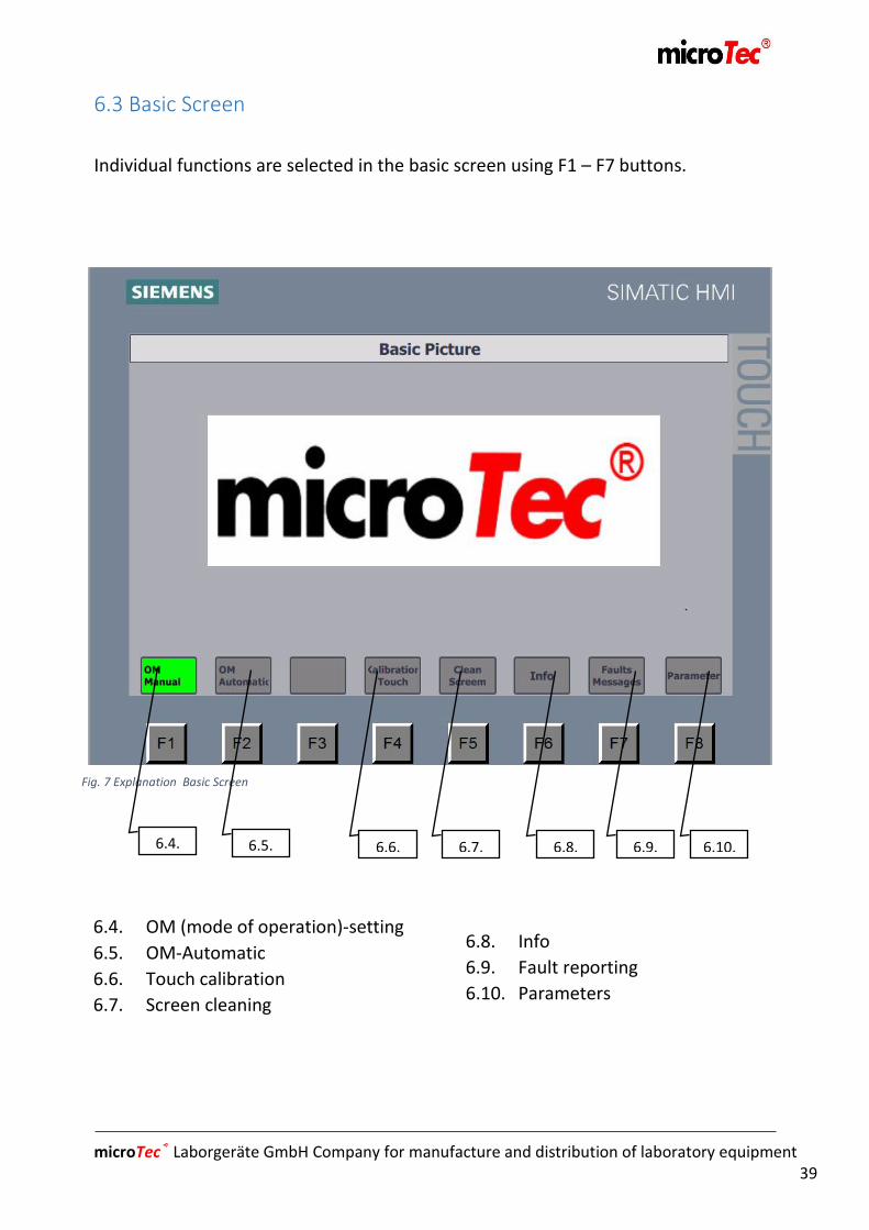
Fig. 7 Explanation Basic Screen
6.4.
6.5.
6.7.
6.8. 6.9. 6.10. 6.6.
6.3 Basic Screen
Individual functions are selected in the basic screen using F1 – F7 buttons.
6.4. OM (mode of operation)-setting
6.5. OM-Automatic
6.6. Touch calibration
6.7. Screen cleaning
6.8. Info
6.9. Fault reporting
6.10. Parameters
microTec® Laborgeräte GmbH Company for manufacture and distribution of laboratory equipment 40
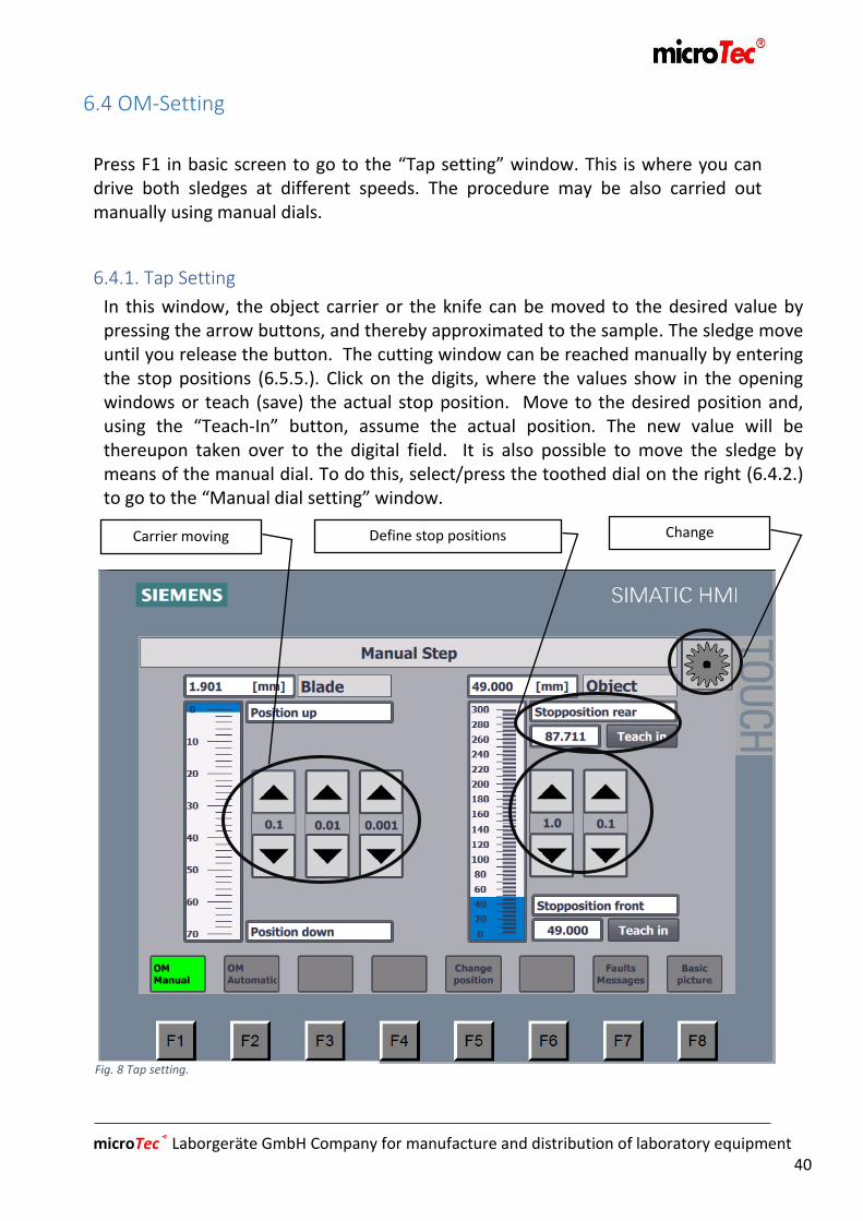
Fig. 8 Tap setting.
Carrier moving Change
tomanualdial
6.4 OM-Setting
Press F1 in basic screen to go to the “Tap setting” window. This is where you can drive both sledges at different speeds. The procedure may be also carried out manually using manual dials.
6.4.1. Tap Setting
In this window, the object carrier or the knife can be moved to the desired value by pressing the arrow buttons, and thereby approximated to the sample. The sledge move until you release the button. The cutting window can be reached manually by entering the stop positions (6.5.5.). Click on the digits, where the values show in the opening windows or teach (save) the actual stop position. Move to the desired position and, using the “Teach-In” button, assume the actual position. The new value will be thereupon taken over to the digital field. It is also possible to move the sledge by means of the manual dial. To do this, select/press the toothed dial on the right (6.4.2.) to go to the “Manual dial setting” window.
Define stop positions

microTec® Laborgeräte GmbH Company for manufacture and distribution of laboratory equipment 41
Fig. 9 Manual Dial Installation
6.4.2. Manual Dial Setting
The manual dial is active only in this window for moving the sledges, selecting the desired value that the sledges should reach pro tact, and turning the manual dial. This is where the stop positions may be defined, too, as described in 6.4.1. Press the arrow to return to “Tap setting”.

microTec® Laborgeräte GmbH Company for manufacture and distribution of laboratory equipment 42
Fig. 10 Change Position
6.4.3. Changing Position
This function may only be used in OM-Setting and is used for releasing the sample or the
knife for the purposes of changing. By activating the “Change position” button, move the
knife carrier to its most upper end position, then move the object carrier to the most
frontal position. The activation of this function will turn the button yellow and indicates
the moving procedure. Upon reaching the change position, the button turns green.

microTec® Laborgeräte GmbH Company for manufacture and distribution of laboratory equipment 43
6.5.1
.
6.5.2
6.5.3
.
6.5.4
6.5.5
Fig. 11 OM-Automatic
6.5 OM-Automatic
The sectioning process is carried out in OM-Automatic (automatic operation). During this
process, the system ignores all the previous OM settings and follows those set during the
sectioning process. The sectioning process may be started either by means of
Touchscreen or with the foot switch.
6.5.1. Display of default values 6.5.2. Display of actual values 6.5.3. Selection of stroke type 6.5.4. Sectioning process functions 6.5.5. Selection of stop positions

microTec® Laborgeräte GmbH Company for manufacture and distribution of laboratory equipment 44
Fig. 12 Defining default values
6.5.1. Display of Default Values
This is where default values are defined, using a finger or an input pen in the white field.
After clicking, window 12. opens. Enter the desired numbers and press Enter to confirm.
This is how you may define all default values, except the “Cutting Speed”, which is to be
set by turning the potentiometer. The setting values are limited by minimum and
maximum values.
microTec® Laborgeräte GmbH Company for manufacture and distribution of laboratory equipment 45
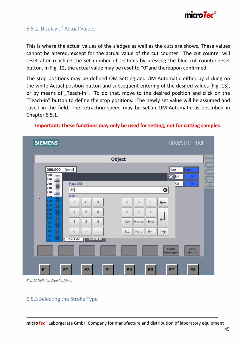
Fig. 13 Defining Stop Positions
6.5.2. Display of Actual Values
This is where the actual values of the sledges as well as the cuts are shows. These values
cannot be altered, except for the actual value of the cut counter. The cut counter will
reset after reaching the set number of sections by pressing the blue cut counter reset
button. In Fig. 12, the actual value may be reset to “0”and thereupon confirmed.
The stop positions may be defined OM-Setting and OM-Automatic either by clicking on
the white Actual position button and subsequent entering of the desired values (Fig. 13),
or by means of „Teach-In“. To do that, move to the desired position and click on the
“Teach-in” button to define the stop positions. The newly set value will be assumed and
saved in the field. The retraction speed may be set in OM-Automatic as described in
Chapter 6.5.1.
Important: These functions may only be used for setting, not for cutting samples.
6.5.3 Selecting the Stroke Type
microTec® Laborgeräte GmbH Company for manufacture and distribution of laboratory equipment 46
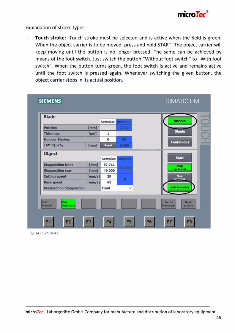
Fig. 14 Touch stroke
Explanation of stroke types:
- Touch stroke: Touch stroke must be selected and is active when the field is green.
When the object carrier is to be moved, press and hold START. The object carrier will
keep moving until the button is no longer pressed. The same can be achieved by
means of the foot switch. Just switch the button “Without foot switch” to “With foot
switch”. When the button turns green, the foot switch is active and remains active
until the foot switch is pressed again. Whenever switching the given button, the
object carrier stops in its actual position.

microTec® Laborgeräte GmbH Company for manufacture and distribution of laboratory equipment 47
Fig. 15 Single Stroke
- Single stroke: The single-stroke function must be selected and is active when the field
turns green. The function may be started either by using Touchscreen or the foot
switch, whereupon the sectioning process is performed once and then the sledge
remains in the preselected stop position.
-
-
-
-
-
-
-
-
microTec® Laborgeräte GmbH Company for manufacture and distribution of laboratory equipment 48
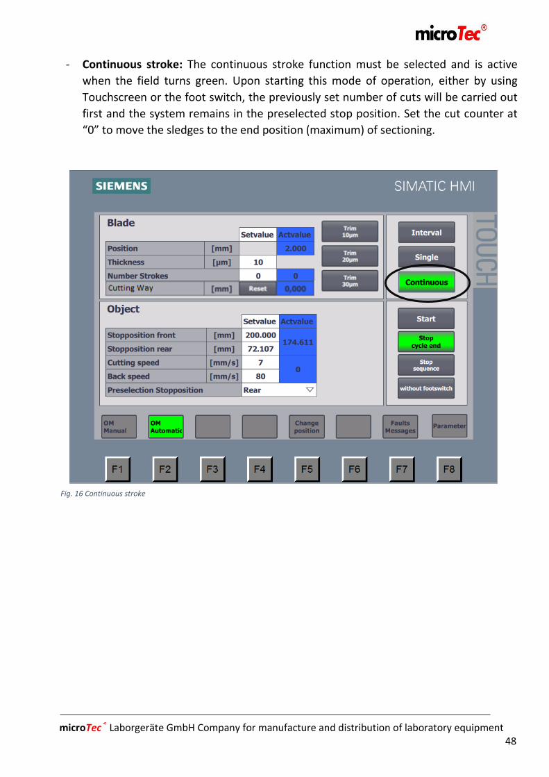
Fig. 16 Continuous stroke
- Continuous stroke: The continuous stroke function must be selected and is active
when the field turns green. Upon starting this mode of operation, either by using
Touchscreen or the foot switch, the previously set number of cuts will be carried out
first and the system remains in the preselected stop position. Set the cut counter at
“0” to move the sledges to the end position (maximum) of sectioning.
microTec® Laborgeräte GmbH Company for manufacture and distribution of laboratory equipment 49
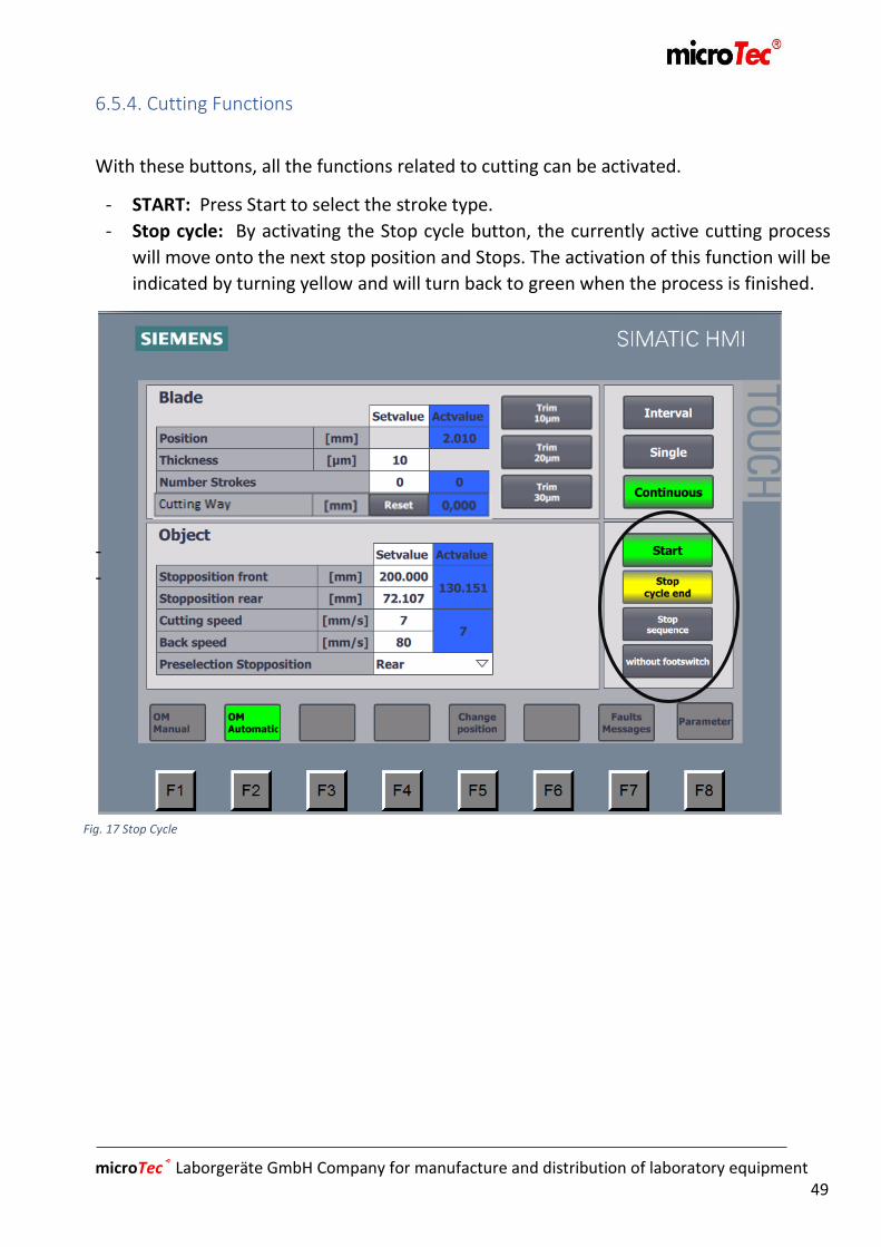
Fig. 17 Stop Cycle
6.5.4. Cutting Functions
With these buttons, all the functions related to cutting can be activated.
- START: Press Start to select the stroke type.
- Stop cycle: By activating the Stop cycle button, the currently active cutting process
will move onto the next stop position and Stops. The activation of this function will be
indicated by turning yellow and will turn back to green when the process is finished.
-
-

microTec® Laborgeräte GmbH Company for manufacture and distribution of laboratory equipment 50
Fig. 18 Stop Process
- Stopping the process: Upon activating the Stop Process function during the cutting
process, the sledge will come to a halt immediately and remain in the actual position,
interrupting thereby the cutting process. The Stop Process button turns red to indicate
activation. To complete the cutting process or start a new one, press START. The sledge
will move from its actual position to the next one or to the end.
-
- Foot Switch: This is where the foot switch can be activated/deactivated. The built-in
Emergency Stop function cannot be affected in any way – it is always active.
microTec® Laborgeräte GmbH Company for manufacture and distribution of laboratory equipment 51
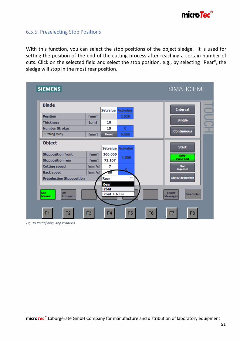
Fig. 19 Predefining Stop Positions
6.5.5. Preselecting Stop Positions
With this function, you can select the stop positions of the object sledge. It is used for setting the position of the end of the cutting process after reaching a certain number of cuts. Click on the selected field and select the stop position, e.g., by selecting "Rear", the sledge will stop in the most rear position.

microTec® Laborgeräte GmbH Company for manufacture and distribution of laboratory equipment 52
Fig. 20 Stop Cycle
Stop Positions during Cutting Process
- Touch Stroke: In the Touch Stroke function, the set-up stop positions will not be
considered, as the object carrier will stop in its actual position after you press START.
- Single Stroke: In the Single Stroke function, the sledge will perform one cut, then move
to the selected stop position and remain there. If the ”Front” stop position has been
selected, the sledge will stop in the front position after the cut and would have to be
restarted by pressing START to perform another cut. If “Front + Rear” is selected, the
sledge will stop at the next stop position, i.e. the sledge will stop at the front and rear
each time and has to be restarted by pressing START to perform another cut.
- Continuous Stroke: In the continuous Stroke mode, the object sledge stops upon passing
the selected stop position after reaching the predefined number of cuts. Additionally, in
the Continuous Stroke mode, it is possible to use the “Stop Cycle” button during the
cutting process. The button will turn yellow to signalize that this function is active. The
sledge stops upon passing the selected stop position, whereupon the button turns green.

microTec® Laborgeräte GmbH Company for manufacture and distribution of laboratory equipment 53
Fig. 21 Trimming
6.5.6. Trimming
Trimming functions appear on display, as soon as the stroke type is changed to Continuous Stroke. They are divided into 10, 20, and 30µm. Trimming is used for quick start of approximating or cutting of samples. Start the function by pressing “Start” in Continuous Stroke and hold the desired trimming thickness until the desired approximation is reached. In the trimming function, the object sledge performs the cutting and retracting motion at a preset speed. Trimming functions are performed independently of the potentiometer’s position.

microTec® Laborgeräte GmbH Company for manufacture and distribution of laboratory equipment 54
Fig. 22 Cutting Way
6.5.7. Sectioning Way
This function will enable you to see how far the sample has been cut. To do this, press the Reset button at the beginning of the cutting process, resetting the counter thereby. The counter will continue to count until it is reset again. It makes no difference, whether the knife or the cut thickness have been changed manually.

microTec® Laborgeräte GmbH Company for manufacture and distribution of laboratory equipment 55
6.6 Touchscreen Calibration
In order to ensure a problem-free functioning of the Touchscreen, it should be
regularly calibrated. This is done by opening the “Calibrate Touch” window and
following the commands on the Touchscreen. Click on free Touch first and then select
the relevant crosses until the process is completed.
6.7 Screen Cleaning
Select Screen Cleaning to clean Touchscreen. The cleaning window opens, with a
bar in it to indicate the remaining cleaning time. When the time is up, the screen
will return to the basic screen. This procedure may be repeated liberally, until
Touch is sufficiently clean.

microTec® Laborgeräte GmbH Company for manufacture and distribution of laboratory equipment 56
Fig. 23 Info Display
6.8 Info
Whenever you need spare part or accessories or a service technician, contact the
Mikrotom-XL Customer Service or the manufacturer, or your Mikrotom-XL dealer. Find
the required data and information in the “Info” window or on the type label:
- Contact for the manufacturer - Year of manufacture of Mikrotom-XL - Machine number - Model name
Please have these data on hand whenever you have a question or problem.
6.9 Fault Reporting / Troubleshooting

microTec® Laborgeräte GmbH Company for manufacture and distribution of laboratory equipment 57
Fig. 24 Fault Reporting / Troubleshooting
This is where occurring problems are to be reported. If an active fault is present, the fault
reporting field turns red. To see this, click on F7. If unable to rectify and release the fault
ourselves (see Troubleshooting), please contact your Mikrotom-XL dealer or Mikrotom-XL
Customer Service or the manufacturer.
microTec® Laborgeräte GmbH Company for manufacture and distribution of laboratory equipment 58
Fig. 25 Parameters
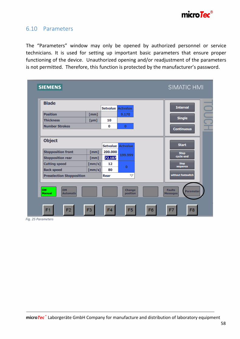
6.10 Parameters
The “Parameters” window may only be opened by authorized personnel or service
technicians. It is used for setting up important basic parameters that ensure proper
functioning of the device. Unauthorized opening and/or readjustment of the parameters
is not permitted. Therefore, this function is protected by the manufacturer’s password.

microTec® Laborgeräte GmbH Company for manufacture and distribution of laboratory equipment 59
Chapter7
Operation
7. Operation. ...................................................................................................... 60
7.1 Sample fixing ...................................................................................................... 60
7.2 Knifesetting or changing .................................................................................... 60
7.2.1 Polycut knife holder Type 1 + 2 ................................................................. 61
7.2.2 Universal knife holder ................................................................................. 63
7.3 Default values defining /Setting ........................................................................ 64
7.4 Knife angle setting ............................................................................................. 65
7.4.1 Polycut knife holder Type 1 + 2 .................................................................. 65
7.4.2 Universal knife holder ................................................................................. 66
7.5 Declination angle setting ................................................................................... 67
7.5.1 Polycut knife holder (Typ 1 + 2) .................................................................. 67
7.5.2 Universal knife holder ................................................................................. 68
7.6 Section thickness and cut number setting......................................................... 68
7.7 Sectioning window ............................................................................................. 68
7.8 Sectioning .......................................................................................................... 69
7.9 Select sectioning speed ..................................................................................... 71
7.10. Taking off sections .......................................................................................... 72

microTec® Laborgeräte GmbH Company for manufacture and distribution of laboratory equipment 60
7. Operation
7.1 Sample Fixing
Move the device in the change position (6.4.3) and make sure, due to a potential risk of
injury, that no knife is fitted in the device or the knife guard closed. Fix the sample using a
suitable clamp and set it on a magnet or the object carrier.
7.2 Knife Fitting or Knife Type Changing
Currently, there are 3 types of knife holders available (see Accessories): - Polycut knife holder, Type 1, turning point around the cutting edge - Polycut knife holder, Type2, turning point around the axis of the guiding slots
Polycut knife holder, Type 1 +2, with changeable fixing plate, for fixing different types of knives
- Universal knife fixture Universal knife holder with changeable adapter bars for fixing different types of knives with one and the same knife holder.

microTec® Laborgeräte GmbH Company for manufacture and distribution of laboratory equipment 61
Finger guard
Screws Clampslider
hieber
Fig. 26 Polycut Knife: change of knives
7.2.1 Polycut knife Typ 1 + 2
!!!Risk of Cutting –Wear Gloves!!!
Open the finger guard by pressing both clamp slides inwards
and flip the finger guard backwards, as shown in the illustration.
Thereupon unscrew the screws (5 pcs) and slide the knife in
sideways. Thereupon screw the screws in again to fix the knife.
Close the finger guard by flipping in forward until it is visibly in
its place and makes a clicking sound.
To fit it another type of knife, unscrew the screws and take
them out along with the fixing plate. Thereupon put in a new
fixing plate and fasten it with the screws again.
microTec® Laborgeräte GmbH Company for manufacture and distribution of laboratory equipment 62
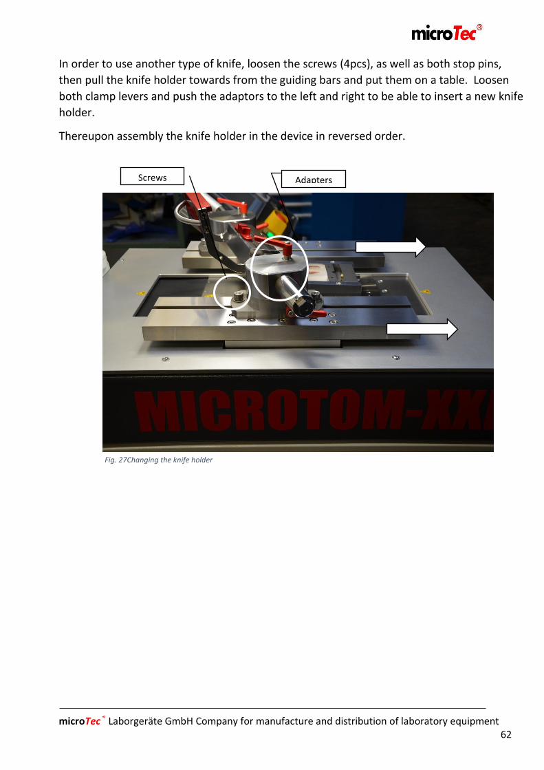
Screws Adapters
Fig. 27Changing the knife holder
In order to use another type of knife, loosen the screws (4pcs), as well as both stop pins,
then pull the knife holder towards from the guiding bars and put them on a table. Loosen
both clamp levers and push the adaptors to the left and right to be able to insert a new knife
holder.
Thereupon assembly the knife holder in the device in reversed order.

microTec® Laborgeräte GmbH Company for manufacture and distribution of laboratory equipment 63
Protection Screws
Clamplever
Fig. 28 Universal Knife Fixture
7.2.2 Universal Knife holder
!!! Risk of Cutting – Wear Gloves!!!
Open the finger guard and put it on the adaptor of the universal
knife fixture, so that the magnets lift it and prevent
unintentional closing. Thereupon, unscrew the 4 screws, insert
the 2 small relief screws, and insert the knife (tip: insert it
sideways). Subsequently, screw the 4 screws in again and the 2
small ones out again to fixate the knife. Close the finger guard
by flipping in forwards, until it is visibly in place with the
magnets holding it.
If wanting to change the type of knife, unscrew the screws and
take them out along with the fitting bar. Subsequently put in a
new fitting bar and fasten the screws again.

microTec® Laborgeräte GmbH Company for manufacture and distribution of laboratory equipment 64
In order to change the knife holder in the knife holder base, loosen the clamp lever and pull it out completely. Caution, the knife fixture could now fall down. Therefore, lift the knife holder to avoid damage. (Tip: Put a thick piece of cloth underneath for protection). Pull the knife holder forwards and insert a new one. Press the knife holder carefully in the toothed wheel and push the shaft back in again from the outside and tighten it.
7.3 Define Default Values /Setting
Go to Default Values Defining in Chapters, 6.4.1. + 6.4.2.and 6.5.1.to 6.5.5.

microTec® Laborgeräte GmbH Company for manufacture and distribution of laboratory equipment 65
Clamplever Angle adjustment
Fig. 29 Polycut Knife holder: Knife Angle Setting
7.4 Knife Angle Setting
Depending on the facet of the knife, angle setting of approx. 10-15° is recommended.
When using a sharpened knife, the height of the knife must be adjusted accordingly.
7.4.1 Polycut Knife holder, Type 1 + 2
In order to set the knife angle, loosen both clamp levers and turn the angle setting to the
desired angle. Thereupon close both clamp levers again.

microTec® Laborgeräte GmbH Company for manufacture and distribution of laboratory equipment 66
Clamplever
Knife angle adjustment
Fig. 30 Universal Knife holder: Knife Angle Adjustment
7.4.2 Universal Knife holder
In order to adjust the knife angle, loosen the clamp lever and using a hex wrench set the required angle. Thereupon, close the clamp lever again.
microTec® Laborgeräte GmbH Company for manufacture and distribution of laboratory equipment 67
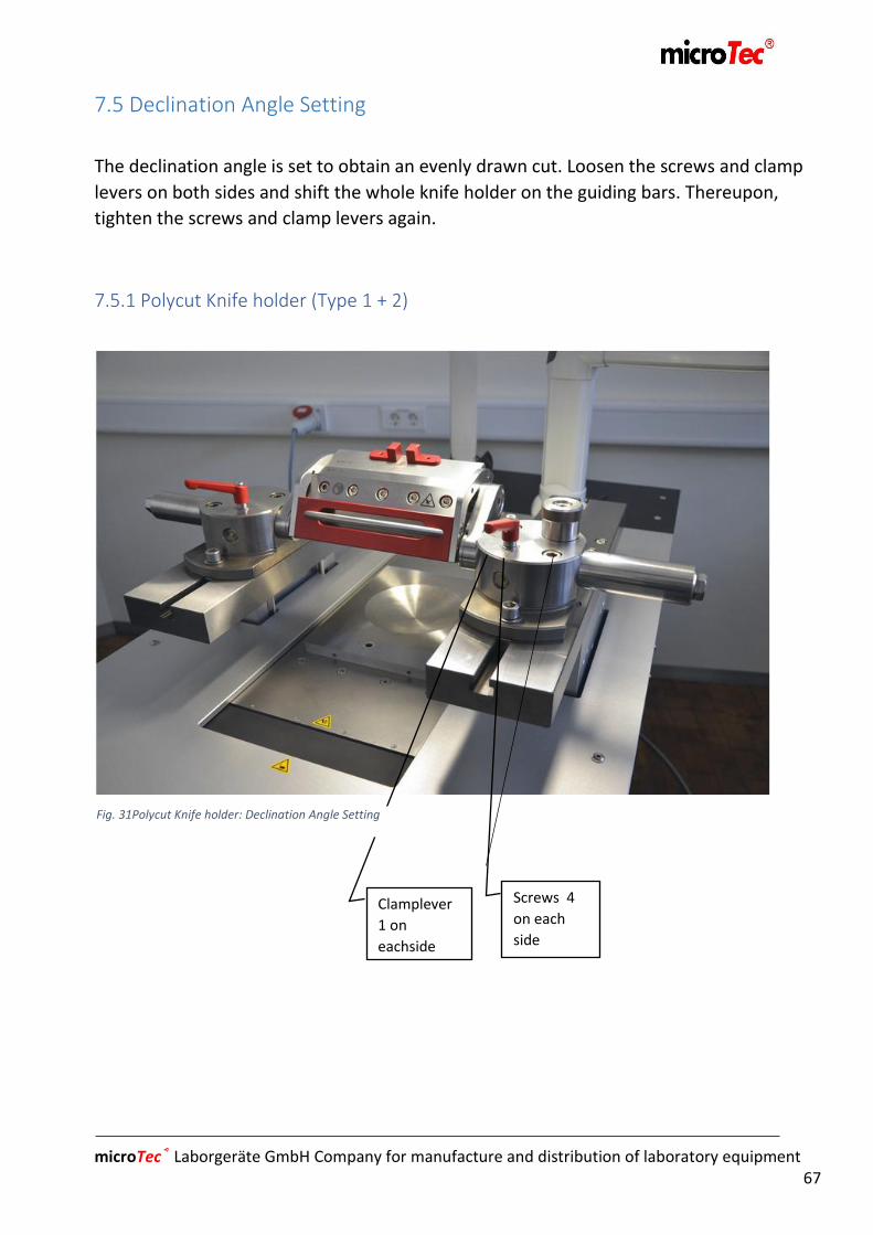
Screws 4
on each
side
Clamplever
1 on
eachside
Fig. 31Polycut Knife holder: Declination Angle Setting
7.5 Declination Angle Setting
The declination angle is set to obtain an evenly drawn cut. Loosen the screws and clamp
levers on both sides and shift the whole knife holder on the guiding bars. Thereupon,
tighten the screws and clamp levers again.
7.5.1 Polycut Knife holder (Type 1 + 2)

microTec® Laborgeräte GmbH Company for manufacture and distribution of laboratory equipment 68
Screws 2 on each
side
Fig. 32 Polycut Knife Fixture: Declination Angle Setting
7.5.2 Universal Knife holder
7.6 Section Thickness and Section Number Setting
Go to Defining the Number of Cuts and proceed as described in Chapters 6.5.1
and 6.5.2.
7.7 Sectioning Window
Go to Defining Cutting Window and proceed as described in Chapter
6.5.1.

microTec® Laborgeräte GmbH Company for manufacture and distribution of laboratory equipment 69
7.8 Sectioning
Make sure that all the required actual values, such as number of cuts, cut thickness, etc.
are correctly defined and that you are in OM-Automatic. Additionally, you should observe
the following points:
- Always use a sharp knife
- When the knife is worn (dull) in one position, shift the knife so that its sharp edge can be
used for sectioning.
- Keep the front and rear side of the knife always clean
It is generally recommended to wear protective glasses when
sectioning samples of any kind to prevent an injury from splinters.
Starting the different cutting stroke types:
See also Chapter 6.5.3
Interval stroke:
Starting via Touchscreen:
- Select the interval stroke, press and hold the START button. The process will continue
in this mode, until the button is no longer pressed (released).
Starting with the foot switch:
- Select the interval stroke and then press the “With foot switch” button. Keep the foot
switch pressed as long as you want the process to continue.
Single stroke:
Starting via Touchscreen:
- Select the “Single stroke” button and then press START. The device will carry out a
single cut and stops in a predefined stop position. If “Stop process” is activated during
the cutting procedure and the device will stop in the current position. Press “START”
again to complete the process.
Starting with the foot switch:
- Select the “Single stroke” button and then press “With foot switch”. While the foot
switch is being pressed, the cutting process will be completed and the object carrier
remains in the predefined stop position. Press the foot switch again to repeat the
process.

microTec® Laborgeräte GmbH Company for manufacture and distribution of laboratory equipment 70
Continuous stroke:
Starting via Touchscreen:
- Select “Continuous stroke” and then press START. The device will carry out either the
preset number of cuts or keep cutting until it reaches the end position. If “Stop
process” is activated during the cutting procedure and the device will stop in the
current position. Press “START” again to complete the process. If the “Stop cycle”
button is pressed, the process will interrupt at the predefined stop position. The
activation of this function is indicated when the button turns yellow. Press “START” to
renew the process. In the continuous-stroke mode, it is possible to set quick
sectioning and approximating t the sample by means of trimming (6.5.6). To do this,
select the desired trim thickness and hold it until the desired position is reached.
Starting with the foot switch:
- Select “Continuous stroke” and then press the function “With foot switch”. Keep
pressing the foot switch until the desired number of cuts or the end position is
reached. Press the foot switch again to make the object carrier stop at a predefined
stop position.

microTec® Laborgeräte GmbH Company for manufacture and distribution of laboratory equipment 71
Fig. 33 Cutting speed
Fig. 34 Potentiometer
7.9 Select Sectioning Speed
Turn the potentiometer to define the cutting speed. The actual sectioning speed value will
be shown in the default field. If no cutting speed is selected, i.e., the potentiometer stands
at Zero, the default field turns red.

microTec® Laborgeräte GmbH Company for manufacture and distribution of laboratory equipment 72
7.10. Taking off sections
Sections are to be taken off by using a suitable tool. The tool should be softer than the
knife and possibly not made of metal. Friction might result in burrs that could damage the
knife or the knife holder. Taking off sections with fingers should be avoided.

microTec® Laborgeräte GmbH Company for manufacture and distribution of laboratory equipment 73
Chapter8
Fault Reporting
8. Fault Reporting. ...................................................................................................... .74

microTec® Laborgeräte GmbH Company for manufacture and distribution of laboratory equipment 74
8. Fault Reporting / Troubleshooting
Fault / Fault Reporting Cause Remedy
The device is not working Main switch is off
Socket contact is loose
Defective fuse
Turn main switch to “I ON”,
Check socket connections,
Change the fuse
Handling inverter fault SPS boots faster than the
inverter
Acknowledge fault as
described in 6.1 + 6.9
Object carrier makes no
cutting movements
Potentiometer in on Zero Turn the potentiometer
Emergency button is active Emergency button has
been pressed at the
operator’s panel or with
the foot switch
1. Turn and pull the Emergency button up 2. Press the blue button at the foot switch to deactivate Emergency stop 3. Acknowledge the fault as described in 6.1 + 6.9
Maximum position reached The object carrier has reached the maximum position, i.e., the end position
Object carriers have to be released manually

microTec® Laborgeräte GmbH Company for manufacture and distribution of laboratory equipment 75
Chapter9
Accessories
9. Accessories .................................................................................................... 76
9.1 Accesory to the knife/ knife holder ................................................................... 76
9.2 Accessories to object fitting andpositioning ..................................................... 79
9.3 Table accesories ................................................................................................. 83

microTec® Laborgeräte GmbH Company for manufacture and distribution of laboratory equipment 76
9. Accessories
9.1 Accessories to the Knife/Knife holder
Knife holder adaptor (polycut knife)
Art. No. B160076
Taking/ Carrier for polycut knife holder
Declination/angle adjustment 90°-135°
Knife angle/fine adjustment 0 - minus 25°
Knife holder KH-CC/CD
Art. No. B160077
Knife holder of stainless steel
Finger guard mechanically stoppable
For parallel Polycut knives with CC or CD edge
Knife holder KH-P (polycut knife)
Art. No. B160078
Knife holder of stainless steel
Finger guard mechanically stoppable
For parallel standard Polycut knives
Adaption knife holder
Knife holder KH-CC/CD
Knife holder KH-P

microTec® Laborgeräte GmbH Company for manufacture and distribution of laboratory equipment 77
Knife holder KH-R (rotary microtome knife)
Art. No. B160079
Knife holder of stainless steel
Finger guard mechanically stoppable
For rotary microtome knives
Knife holder KH-S
Art. No. B160080
Knife holder of stainless steel
Finger guard mechanically stoppable
For standard knives up to 220mm
Knife holder KH-E
Art. No. B160081
Knife holder of stainless steel
Finger guard mechanically stoppable
For disposable low-profile blades up to 180mm
Knife holder KH-R
Knife holder KH-S
Knife holder KH-E

microTec® Laborgeräte GmbH Company for manufacture and distribution of laboratory equipment 78
Special knife holder
Art. No. B160082
Knife holder of stainless steel
For direct fixation of diverse microtome knives
Knife with knife box
Art. No. H160094
Different knives with knife box available
Adaption Universal knife holder
Art. No. F160158
Sledge bar for universal knife holder
Declination/Angle adjustment 90°-135°
Universal knife on sledge bar, freely slidable (thus
possible to be used with any knife, without new cut
starting)
Special knifefixture
Adaption Universal knife holder
Knifebox with knife

microTec® Laborgeräte GmbH Company for manufacture and distribution of laboratory equipment 79
Universal knife holder
Art. No. B160083
Universal knife holder for standard microtome knives
„C“ and „D“
Knife holder of hardened stainless steel
Knife angle adjustment -5 to -25° (right to left
adjustable and readable)
Clamp bar changeable for „C“ and „D“ knives
Knife positioning with fine adjustment by means of
two laterally mounted nuts
Safety finger guard
9.2 Object Fixation and Positioning Accessories
Universal fixation frame
Art. No. B160084
Fixation frame, size 90x100mm
Fixation Vice S1 Industrial Version
Art. No. H160095
Manual screwing vice
Back width 64mm
Fixation width 67mm
Universal knife holder
Universal fixationframe
Fixation vice S1
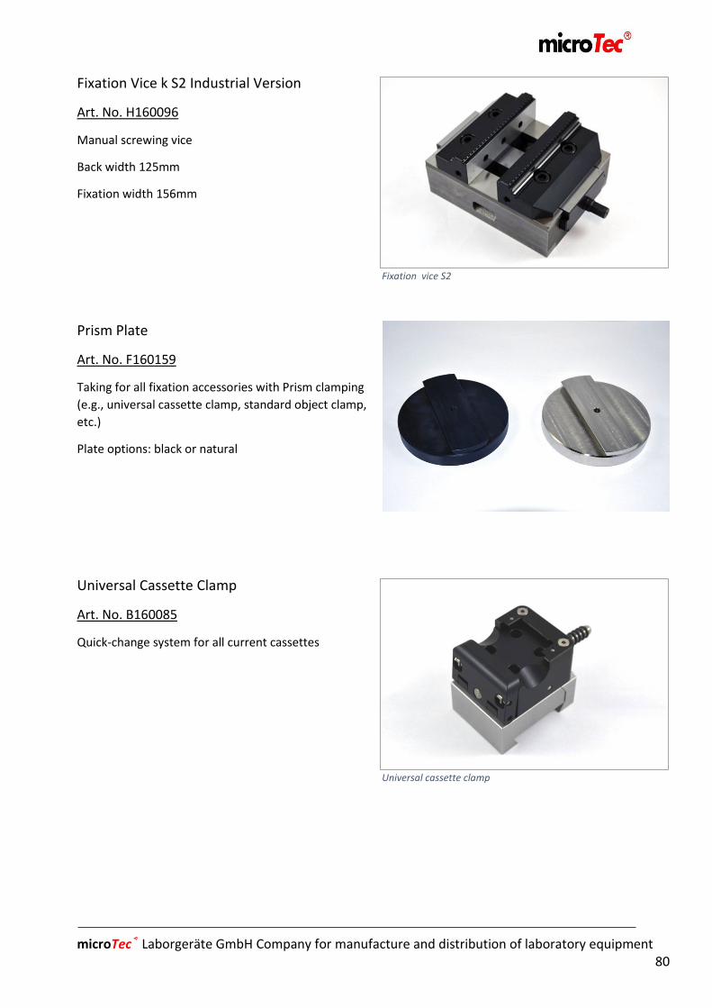
microTec® Laborgeräte GmbH Company for manufacture and distribution of laboratory equipment 80
Fixation Vice k S2 Industrial Version
Art. No. H160096
Manual screwing vice
Back width 125mm
Fixation width 156mm
Prism Plate
Art. No. F160159
Taking for all fixation accessories with Prism clamping
(e.g., universal cassette clamp, standard object clamp,
etc.)
Plate options: black or natural
Universal Cassette Clamp
Art. No. B160085
Quick-change system for all current cassettes
Fixation vice S2
Universal cassette clamp
Prism plate
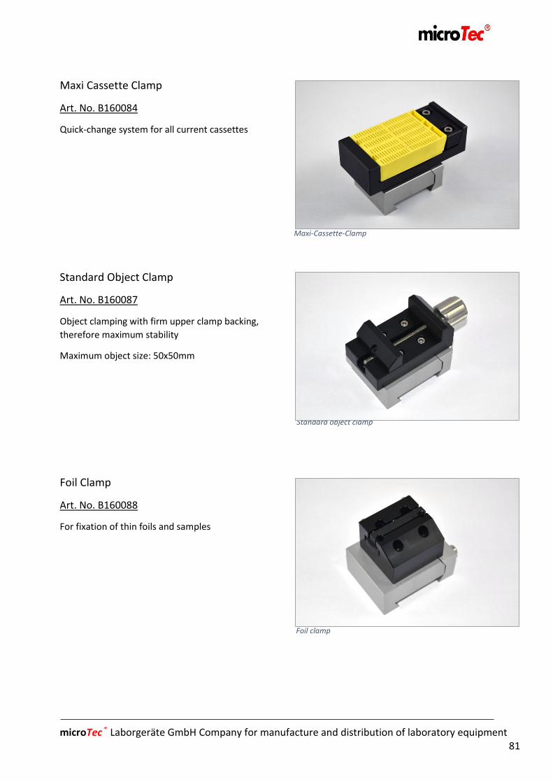
microTec® Laborgeräte GmbH Company for manufacture and distribution of laboratory equipment 81
Maxi Cassette Clamp
Art. No. B160084
Quick-change system for all current cassettes
Standard Object Clamp
Art. No. B160087
Object clamping with firm upper clamp backing,
therefore maximum stability
Maximum object size: 50x50mm
Foil Clamp
Art. No. B160088
For fixation of thin foils and samples
Maxi-Cassette-Clamp
Standard object clamp
Foil clamp

microTec® Laborgeräte GmbH Company for manufacture and distribution of laboratory equipment 82
Application for round samples
Art. No. B160089 (Ø6)
Art. No. B160090 (Ø15)
Art. No. B160091 (Ø19)
Art. No. B160092 (Ø25)
For problem-free fixation of round samples with
defined diameter in connection with standard object
clamp
Round sample sizes: Ø6 / Ø15 / Ø19 / Ø25mm
Optionally also special dimensions
Mini Flat/ Prism Fixture
Art. No. B160093
Fixture for small, flat and round samples
Object orientation / positioning
Art. No. B160094
Objectorientation with mechanical quick-clamping
Angle range ±5°
Turning range 360°
Round samples
Mini flat/ prismfixture
Object orientation / positioning

microTec® Laborgeräte GmbH Company for manufacture and distribution of laboratory equipment 83
Adapter plate
Art. No. F160160
For object orientation on a magnet plate (Will be
needed for fastening the fixation frame, screwing
vice, i.a. directly on the magnet plate)
9.3 Table accessory
Paraffin Table T1
Art. No.F160161
Paraffin table, size 96x96mm
Paraffin Table T2
Art. No. F160162 Paraffin table, size 146x146mm
Paraffin Table T3
Art. No. F160163
Paraffin table, size 196x196mm
Adapter plate
Paraffin table 146x146
microTec® Laborgeräte GmbH Company for manufacture and distribution of laboratory equipment 84
Chapter10
Basic Instructions
10. Disposal of waste .......................................................................................... 85

microTec® Laborgeräte GmbH Company for manufacture and distribution of laboratory equipment 85
10. Disposal of waste
The device and accessories must be disposed of in strict compliance with the relevant
regulations.

microTec® Laborgeräte GmbH Company for manufacture and distribution of laboratory equipment 86
Chapter11
Emergency Service, Customer Service
11. Emergency Service, Customer Service ........................................................... 87
11.1 Address ........................................................................................................... 87
11.2 Instruction for Emergency and Customer Serivices ........................................ 87

microTec® Laborgeräte GmbH Company for manufacture and distribution of laboratory equipment 87
11. Emergency Service, Customer Service
11.1 Address
microTec Laborgeräte GmbH
Rudolf-Diesel-Str. 47 D-69190 Walldorf/Baden Tel: + 49 (0) 6227 / 8222-0 Fax: + 49 (0) 6227 / 8222-30 [email protected] www.micro-tec.de
11.2 Instruction for Emergency and Customer Services
In the event that you need spare parts or additional accessories or the Technical Customer
Service, please contact Mikrotom-XL Customer Service or your Mikrotom-XL dealer.
Please have the following information ready:
- Date of delivery
- Reason for requiring Customer Service
- Brief problem description
- Model name and serial number
- Location and contact person

microTec® Laborgeräte GmbH Company for manufacture and distribution of laboratory equipment 88
Chapter12
List of Figures (Illustrations)
12. List of Figures/Illustrations ………………………………… ........................... …………… 89
microTec® Laborgeräte GmbH Company for manufacture and distribution of laboratory equipment 89
12. List of Figures/Illustrations
Fig. 1 Accessories ............................................................................................................................................................ 33
Fig. 2 Mikrotom-XL .......................................................................................................................................................... 34
Fig. 3 Foot switch ............................................................................................................................................................ 35
Fig. 4 Potentiometer & manual dials ............................................................................................................................. 35
Fig. 5 Basic screen / Start screen .................................................................................................................................... 37
Fig. 6 Error Messages ...................................................................................................................................................... 38
Fig. 7 Exlanation re Basic Screen ..................................................................................................................................... 39
Fig. 8 Tap setting. ............................................................................................................................................................ 40
Fig. 9 Manual Dial Installation ......................................................................................................................................... 41
Fig. 10 Change Position ................................................................................................................................................... 42
Fig. 11 OM-Automatic ..................................................................................................................................................... 43
Fig. 12 Defining default values ........................................................................................................................................ 44
Fig. 13 Defining Stop Positions ........................................................................................................................................ 45
Fig. 14 Touch stroke ........................................................................................................................................................ 46
Fig. 15 Single Stroke ........................................................................................................................................................ 47
Fig. 16 Continuous stroke ............................................................................................................................................... 48
Fig. 17 Halt Cycle ............................................................................................................................................................. 49
Fig. 18 Stop Process ........................................................................................................................................................ 50
Fig. 19 Predefining Stop Positions ................................................................................................................................... 51
Fig. 20 Halt Cycle ............................................................................................................................................................. 52
Fig. 21 Trimming.............................................................................................................................................................. 53
Fig. 22 Sectioning Window .............................................................................................................................................. 54
Fig. 23 Info Display .......................................................................................................................................................... 56
Fig. 24 Fault Reporting / Troubleshooting ...................................................................................................................... 57
Fig. 25 Parameters .......................................................................................................................................................... 58
Fig. 26 Polycut Knife: change of knives ........................................................................................................................... 61
Fig. 27 Changing the Knife holder ................................................................................................................................... 62
Fig. 28 Universal Knife holder ......................................................................................................................................... 63
Fig. 29 Polycut Knife holder: Knife Angle Setting ........................................................................................................... 65
Fig. 30 Universal Knife holder: Knife Angle Adjustment ................................................................................................. 66
Fig. 31 Polycut Knife holder: Declination Angle Setting .................................................................................................. 67
Fig. 32 Polycut Knife holder: Declination Angle Setting .................................................................................................. 68
Fig. 33 Cutting speed ....................................................................................................................................................... 71
Fig. 34 Potentiometer ..................................................................................................................................................... 71

microTec® Laborgeräte GmbH Company for manufacture and distribution of laboratory equipment 90
Chapter13
Notes
13 Notes ............................................................................................................. 91

microTec® Laborgeräte GmbH Company for manufacture and distribution of laboratory equipment 91
13. Notes