laser clean heating system/vented heater … heaters/name... · laser clean vented model laser 60at...
TRANSCRIPT
LASER CLEAN VENTED
MODEL Laser 60AT
CONTENTS
IMPORTANT
READ AND UNDERSTAND INSTRUCTIONS BEFORE INSTALLING OR USING HEATER.RETAIN INSTRUCTIONS FOR FUTURE REFERENCE. CHECK LOCAL CODES FOR PERMITTED USE.
LASER CLEAN HEATING SYSTEM/VENTED HEATERINSTALLATION AND OPERATION INSTRUCTIONS
SECTION A:SpecificationsSafety Features
SECTION B:Safety Tips for Operation
SECTION C:Fuel Guide
SECTION D:Operating Controls and Part Names
SECTION E:Operation
Before IgnitionOperationTurning Heater Off
SECTION F:Routine Maintenance
················································ 2 ·············································· 3
································ 4
···················································· 5
················· 6
··········································· 9·················································· 9
···································· 12
···································· 12
············································ 14
········································ 16
······················ 17························· 17
········································ 19·························· 22
············· 23
························································ 29
SECTION G:Troubleshooting
SECTION H:Long Term Storage
SECTION I:Installation
Tools Needed for InstallationStandard Installation PartsAccessary PartsSafety Tips for InstallationInstallation of Heater and Flue Pipe
SECTION J:Fueling

SECTION A:SPECIFICATIONS
Model:
Heater Efficiency:
Heat Rating:
Fuel Consumption:
Fuel System:
Fuel Type:
Dimensions (W ´ H ´ D):(Includes drip tray)
Weight:
Vent Pipe Hole:
Maximum Length of Vent Pipe System:
Electrical Rating:
Typical Room Size (3):
Laser 60AT
90% (1)
High - 30,000 BTU/h (8,800 Watts)Med - 21,000 BTU/h (6,160 Watts)Low - 12,000 BTU/h (3,520 Watts)
High - 0.230 gal/h (0.870 L/h)Med - 0.161 gal/h (0.609 L/h)Low - 0.095 gal/h (0.360 L/h)
External tank (2)
ASTM D3699 1-K Kerosene or ASTM D396 No.1 Fuel Oil
30“ ´ 24“ ´ 19“(76.0 ´ 60.8 ´ 48.3 cm)
77 lbs. (35 kg) Empty
2-3/4“ ~ 3“ diameter(7.0 - 7.5 cm)
10 ft. (3 m), 3 bends or less
120 Volts AC, 60 HzPreheat - 280WBurning - 76W
1250 square feet (0˚F)1500 square feet (20˚F)
(1)
(2)
(3)
Heat and vaporized water are produced by the combustion process of this kerosene heater. This rating does not take into account heat loss due to condensation of water vapor.
External tank to be purchased from local suppliers.
0˚ F Heat Load = 24 BTU/ft2/hr20˚ F Heat Load = 20 BTU/ft2/hr
Room size for which this heater is suitable will vary depending on outside temperature, house insulation, window size, and other factors.
2

SAFETY FEATURES
Your Laser 60AT is equipped with the following safety features. Please familiarize yourself with these
features. When your heater is extinguished due to a safety mechanism, be sure to identify and correct the
problem.
Flame Sensor
Heater will automatically stop all operations if ignition fails or if flame fails during combustion, in order to prevent fuel overflow. Error code will be displayed on the digital indicator.
Fuel Strainer
Special strainer catches any dirt or impurities present in the fuel before it is sent to the burner.
Overheat Protector
Automatically stops all operations if heater cabinet reaches abnormally high temperature due to motor malfunction or abnormal combustion, in order to prevent fire.
Power Failure Recovery System
If power fails during heater operation, heater will turn off. When power resumes, heater will automatically reignite to maintain the selected room temperature.
Fully Vented System
Flue pipe system provides outside air for combustion and vents all combustion products to the outdoors.
Fusible Link Valve
If a household fire should occur, bringing the fuel line or heater to extremely high temperatures, the fusible link valve will stop the fuel supply to the burner. This will prevent the fuel supply from the external tank continuing to flow into the house.
1.
2.
3.
4.
5.
6.
Exhaust fan
Exhaust gas
5. Flue pipe
Intake air
Blower motor
Adjustable leg
Draft pipe Burner
Drip tray
2. Fuel strainer
Fuel sump
Fuel pump
Reset button
Fuel pipe
Burner ring
Ceramic log
Glass cylinder
Intake fan
Igniter 1. Flame sensor
Heat exchanger
3. Overheat protector
3
CAUTION:
0 20 40 60
-20A
B
Room Temperature (˚F)
Ou
tsid
e Te
mp
erat
ure
(˚F
)
-25
-30
-35
-40
-45
SECTION B:SAFETY TIPS FOR OPERATION
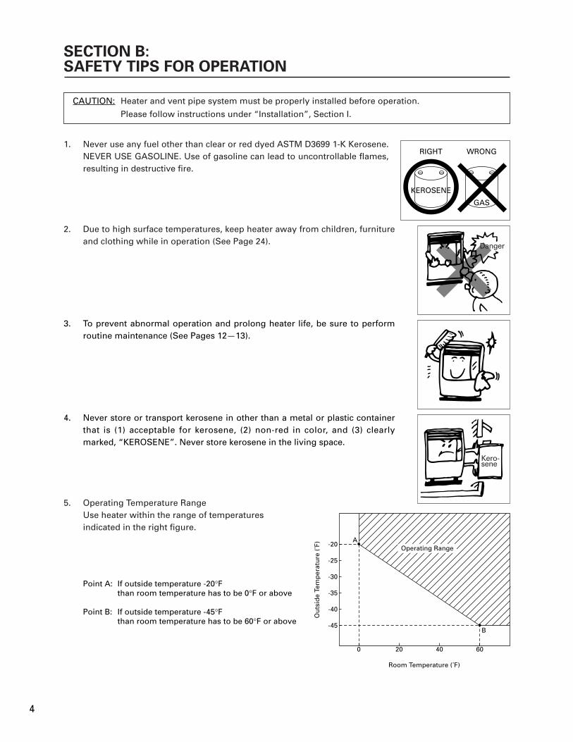
If outside temperature -20°Fthan room temperature has to be 0°F or above
If outside temperature -45°Fthan room temperature has to be 60°F or above
Point A:
Point B:
RIGHT
KEROSENEKEROSENE
WRONG
GAS
Heater and vent pipe system must be properly installed before operation.
Please follow instructions under “Installation”, Section I.
Never use any fuel other than clear or red dyed ASTM D3699 1-K Kerosene. NEVER USE GASOLINE. Use of gasoline can lead to uncontrollable flames, resulting in destructive fire.
1.
Due to high surface temperatures, keep heater away from children, furniture and clothing while in operation (See Page 24).
2.
To prevent abnormal operation and prolong heater life, be sure to perform routine maintenance (See Pages 12-13).
3.
Never store or transport kerosene in other than a metal or plastic container that is (1) acceptable for kerosene, (2) non-red in color, and (3) clearly marked, “KEROSENE”. Never store kerosene in the living space.
4.
Operating Temperature RangeUse heater within the range of temperaturesindicated in the right figure.
5.
Operating Range
Kero-sene
Danger
4
SECTION C:FUEL GUIDE
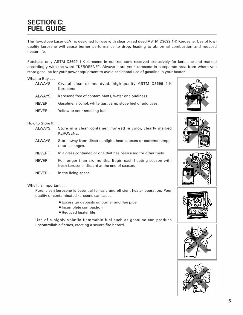
The Toyostove Laser 60AT is designed for use with clear or red dyed ASTM D3699 1-K Kerosene. Use of low-quality kerosene will cause burner performance to drop, leading to abnormal combustion and reduced heater life.
Purchase only ASTM D3699 1-K kerosene in non-red cans reserved exclusively for kerosene and marked accordingly with the word “KEROSENE”. Always store your kerosene in a separate area from where you store gasoline for your power equipment to avoid accidental use of gasoline in your heater.
Crystal clear or red dyed, high-quality ASTM D3699 1-K Kerosene.
Kerosene free of contaminants, water or cloudiness.
Gasoline, alcohol, white gas, camp stove fuel or additives.
Yellow or sour-smelling fuel.
Store in a clean container, non-red in color, clearly marked KEROSENE.
Store away from direct sunlight, heat sources or extreme tempe-rature changes.
In a glass container, or one that has been used for other fuels.
For longer than six months. Begin each heating season with fresh kerosene; discard at the end of season.
In the living space.
¡Excess tar deposits on burner and flue pipe¡Incomplete combustion¡Reduced heater life
What to Buy . . .ALWAYS :
ALWAYS :
NEVER :
NEVER :
How to Store It . . .ALWAYS :
ALWAYS :
NEVER :
NEVER :
NEVER :
Why It is Important . . .Pure, clean kerosene is essential for safe and efficient heater operation. Poor quality or contaminated kerosene can cause:
Use of a highly volatile flammable fuel such as gasoline can produce uncontrollable flames, creating a severe fire hazard.
GAS
5
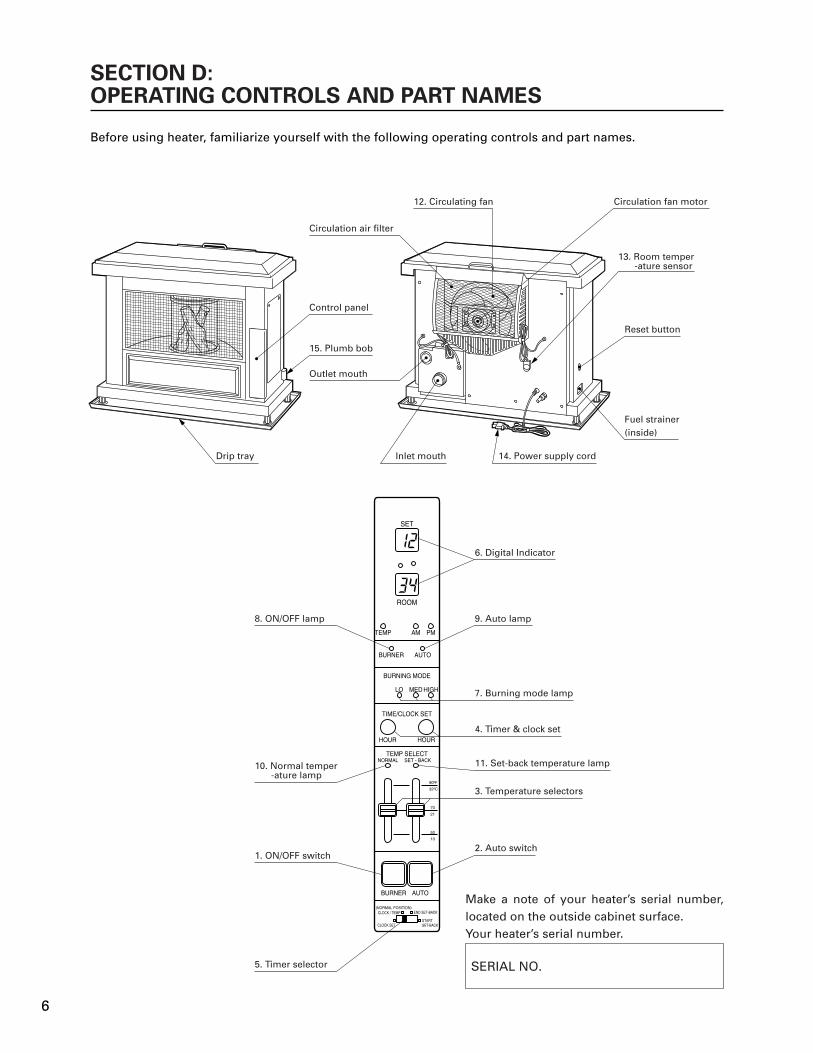
Before using heater, familiarize yourself with the following operating controls and part names.
SECTION D:OPERATING CONTROLS AND PART NAMES
Make a note of your heater’s serial number, located on the outside cabinet surface.Your heater’s serial number.
SERIAL NO.
ROOM
SET
TEMP
BURNER
LO MED HIGH
BURNING MODE
TIME/CLOCK SET
TEMP SELECT
HOUR
BURNER
(NORMAL POSITION)
CLOCK SET
CLOCK / TEMP
STARTSET-BACK
50
10
70
21
90ºF
32ºC
END SET-BACK
SET - BACKNORMAL
AUTO
AM PM
HOUR
AUTO
8. ON/OFF lamp
10. Normal temper-ature lamp
1. ON/OFF switch
5. Timer selector
3. Temperature selectors
11. Set-back temperature lamp
4. Timer & clock set
7. Burning mode lamp
9. Auto lamp
6. Digital Indicator
Circulation air filter
12. Circulating fan Circulation fan motor
13. Room temper-ature sensor
Reset button
Fuel strainer(inside)
15. Plumb bob
Outlet mouth
Control panel
Drip tray Inlet mouth 14. Power supply cord
2. Auto switch
6

Main switch which turns heater on and off. When switched on, heater begins operation and combustion starts after preheat period.
The switch turns automatic operation modes on and off which have been programmed into timer.
“NORMAL” and “SET-BACK” temperature selectors allow user to select desired temperature during manual or automatic operation.
Timer and clock set modes can be set by pressing hour or minute buttons.
Clock, clock set, “SET-BACK” mode, start time set and end time set can be selected by this switch.
Displays clock, set temperature, room temperature and error code.
Indicates whether heater is operating at high, medium or low combustion.
Lights when heater is in operation and flashes when heater is in prepurge or postpurge.
Lights when automatic operation is in use.
Lights when heater runs with manual or “NORMAL” mode of automatic operation.
Lights when heater runs with “SET-BACK” mode of automatic operation.
Three-speed motor supplies high-capacity warm air flow during high combustion for heating room up quickly, and low or medi-umcapacity warm air flow during low or medium combustion for maintaining comfortable room temperature.
Constantly senses room temperature and supplies information to heater so that desired room temperature can be maintained.
For use in 120V, AC electrical outlets only.
Allows user to check if heater is positioned evenly.
1. ON/OFF switch:
2. Auto switch:
3. Temperature selectors:
4. Timer & clock set:
5. Timer selector:
6. Digital indicator:
7. Burning mode lamp:
8. ON/OFF lamp:
9. Auto lamp:
10. Normal temperature lamp:
11. Set-back temperature lamp:
12. Circulating fan:
13. Room temperature sensor:
14. Power supply cord:
15. Plumb bob:
INDICATOR LAMPS
ON/OFF lamp
AUTO lamp
LOW lamp
MED lamp
HIGH lamp
NORMAL lamp
SET-BACK lamp
Flashing - Pre-heating, pre-purging and post-purging modeLit - Heater in operation
Flashing - Power loss of more than 10 secondsLit - Heater in operation at auto mode
Lit - Heater in operation at low combustion
Flashing - Pre-purging mode (without flame)Lit - Heater in operation at medium combustion
Lit - Heater in operation at high combustion
Lit - Heater in operation at normal mode
Lit - Heater in operation at set-back mode
7

REF # PART # PART NAME REF # PART # PART NAME REF # PART # PART NAME
41
40
39
7656
57
55
64
3
4
64
6464
29
6445
70
6073
63
6468
67
19
11
64
12
19
63
6469
3477
7521
1661
38
10
1
71
6428
26
2322
5253
64
64
64
64
6464 64
49
64
252427
6431
332037
36
32
63
63
74
5044
43
424835
47
5163
4646
64
65
65
58
62
636
9
30
72
7059
64
63
7254
63
66
63
64
63
63 64
8
14
15
16
18
17
13
5
123456789101112131415161718192021222324252627
282930313233343536373839404142434445464748495051525354
55565758596061626364656667686970717273747576777879
204799462045000720479570204799292047996020479963204799702047996420479931204799032047997220479940204799442047994520479955204799812047990920479908204758772047994220479943204780262047838320479518171855802047492120474920
204799112047519420479937204799472047887120475883204758752047587820478534204799192047994120478550204755512047555220478512204783782047837920479983204783062047997620479901204799172047991420479915100055972047995220479969
20478373204798912047492520479935204750712047836620479987204740592047995620474050204761462047995820474051204764522047555420476454204740532047405520474057204501202047587420474272204799572047999520479999
Front panelPlumb bobAdjustable legDrip trayTop plateRight side panelAccess panelLeft side panelControl panel doorGrilleFan coverCirculation air filterHeat exchangerCanopyCanopy gasketGlass cylinder gasketGlass cylinderCeramic logO-ring (P75)Burner assemblyBurner ringFuel nozzleFuel nozzle gasketIgniterIgniter gasketIgniter guide gasketIgniter cover
Primary flame rodBurner gasketBlower motor assemblyBlower motor assembly with caseBlower motor exhaust fanBlower motor intake fanBlower motor case gasketRubber matFuel sumpFuel pumpFuel pipe assemblyFuel inlet strainerDrain screw with o-ringStrainer gasketMain circuit boardFuse A (10A)Fuse B (5A)Outlet adapterHigh limit switch (=20474506)Indicator lamp circuitKnob for temp selectorTransformerPCB supportPCB support (S)Fusible link valveLeveler fuel pipeCirculation fan motor
ThermistorFlue pipeOil catchPower supply cordCirculation fanAir damper (P25)Draft tubeHolder AScrew AT1Screw C (=20478091)Screw 1EScrew AT2Screw DScrew B2Screw 1QScrew B4Screw FScrew OFlange NutScrew for igniter unitWasher for blower motorScrew MNut JInstruction manualCarton
8

BEFORE IGNITION
4.
OPERATION
SECTION E:OPERATION
MANUAL OPERATION
Open the Valve(s)
Open the valve(s) of the external fuel tank.
Start the Fuel flow
If using heater for the first time, or after heater has been out of fuel, press the red reset button once for a period of one second in order to send fuel to the fuel sump.
Plug in the Heater
Plug heater into a 120V AC electrical outlet.Note: Do not connect to an outlet shared with other appliances.
C. Position timer selector to “CLOCK/TEMP (NORMAL POSITION)” after clock setting is completed.Current time will be shown on digital indicator.
In the event of a power failure over ten (10) seconds, all clock and timer settings are cancelled. Digital indicator will flash “PM 12:00” when heater is off, or “AUTO” lamp will flash when heater is on and in automatic operation, after is power is restored. However, no indications when heater is in manual operation. At this point, you need to reset all time and set-back functions.
Note:
“MANUAL” operation means that the set-back will not be in use but in ”NORMAL” mode.Operation of the heater is under the direct control of the user (“AUTO” switch is off). Heat output will, however, be automatically adjusted in accordance with the room temperature registered by the temperature sensor.
Operation of Laser Heater can be controlled manually by the user - “MANUAL” operation (NORMAL mode only) or run automatically by the programming - ”AUTOMATIC” operation (NORMAL mode and SET-BACK mode).
3.
Set Clock
Important: Clock on the heater always must be set to current time.
A. Position timer selector to “CLOCK SET”.
B. Press “HOUR” and “MINUTE” button of TIMER/CLOCK SET to correct time.
Important: Check for the AM or PM indicators, to insure the correct time.
4.
Note: Make sure there is no fuel leakage from the fuel line or joints.Also make sure fuel tank is not too high. See installation instructions.
1.
2.
“HOUR” or “MINUTE” button will change the time every one (1) unit. Holding the button continuously will cause the time to change rapidly.
Note:
ROOM
SET
TEMP
BURNER
LO MED HIGH
BURNING MODE
TIME/CLOCK SET
TEMP SELECT
HOUR
BURNER
(NORMAL POSITION)
CLOCK SET
CLOCK / TEMP
STARTSET-BACK
50
10
70
21
90ºF
32ºC
END SET-BACK
SET - BACKNORMAL
AUTO
AM PM
HOUR
AUTO
8. ON/OFF lamp
10. Normal temper- ature lamp
1. ON/OFF switch
5. Timer selector
3. Temperature selectors
11. Set-back temper- ature lamp
4. Timer & clock set
7. Burning mode lamp
9. Auto lamp
6. Digital Indicator
2. Auto switch
Reset Button
9

1. Select Manual Operation
Press the “AUTO” switch to “OFF” position.
2. Turn Heater ON
A. Push in ON/OFF switch to “ON” position. The current room temperature and the set temperature will be shown on the digital indicator. ON/OFF lamp will start to flash and then blower motor and ignition will start.
Note: Heater will not start when room temperature is higher than the desired temperature setting.
B. Burning mode lamp “MED” will start to flash after approx. 3 - 9 minutes and ignition will take place. (*) After ignition, burning mode lamp “MED” will change from flashing to continuous. And, after 10 seconds, burning mode lamp will turn to “LOW” and heater will start “LOW” burning mode. Circulation fan will turn on after approx. 3 minutes.Note: (*) Pre -heating depends on the room temperature.
Room temperature: below 34°F - 9 minutes34°F - 61°F - 6 minutesover 61°F - 3 minutes
C. Heater will operate at “LOW” or “MED” burning mode for approx. 6 min-utes after ignition, regardless of temperature control setting. Heater will not go into “HIGH” burning mode while the prepurging is in effect. After this period, output can be adjusted as desired by using the ”NORMAL” temperature selector as directed in following instructions.
3. Adjusting Room Temperature
A. Slide “NORMAL” temperature selector to set the room temperature desired. The temperature control should be set at the position you find most comfortable.
Note: Desired temperature setting will be displayed on the digital indicator when you set the room temperature.
Note: The scale on temperature selector is just for your reference. The figures on the digital indicator and on the scale may not match exactly; This is normal.
B. Burning mode will be regulated automatically in accordance with the room temperature registered by the room temperature sensor. Heater will be operated at “HIGH” burning mode until room tempera-ture reaches the selected temperature level.
C. When room temperature reaches the selected setting, heater will automatically shift to “MED” or “LOW” burning mode to maintain the desired temperature.When room temperature exceeds the selected setting by approx. 4°F, the heater will automatically shut off. As room temperature drops, the heater will automatically re-start to maintain the desired temperature.
BURNER
(NORMAL POSITION)
CLOCK SET
CLOCK / TEMP
STARTSET-BACK
50
10
70
21
90 F
32ºC
END SET-BACK
AUTO
BURNER
(NORMAL POSITION)
CLOCK SET
CLOCK / TEMP
STARTSET-BACK
50
10
70
21
90 F
32ºC
END SET-BACK
AUTO
BURNER
(NORMAL POSITION)
CLOCK SET
CLOCK / TEMP
STARTSET-BACK
50
10
70
21
90 F
32ºC
END SET-BACK
AUTO
ROOM
TEMP
BURNER
LO MED HIGH
BURNING MODE
AUTO
AM PM
ROOM
TEMP
BURNER
LO MED HIGH
BURNING MODE
AUTO
AM PM
10
Ex.
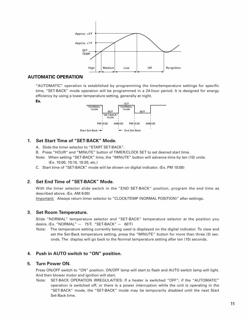
“AUTOMATIC” operation is established by programming the time/temperature settings for specific time, “SET-BACK” mode operation will be programmed in a 24-hour period. It is designed for energy efficiency by using a lower temperature setting, generally at night.
1. Set Start Time of “SET-BACK” Mode.
A. Slide the timer selector to “START SET-BACK”.B. Press “HOUR“ and “MINUTE” button of TIMER/CLOCK SET to set desired start time.Note: When setting “SET-BACK” time, the “MINUTE” button will advance time by ten (10) units.
(Ex. 10:00, 10:10, 10:20, etc.)C. Start time of “SET-BACK” mode will be shown on digital indicator. (Ex. PM 10:00)
2. Set End Time of “SET-BACK” Mode.
With the timer selector slide switch in the “END SET-BACK” position, program the end time as described above. (Ex. AM 6:00)Important: Always return timer selector to “CLOCK/TEMP (NORMAL POSITION)” after settings.
3. Set Room Temperature.
Slide “NORMAL” temperature selector and “SET-BACK” temperature selector at the position you desire. (Ex. “NORMAL” - 75˚F, “SET-BACK” - 60˚F)Note: The temperature setting currently being used is displayed on the digital indicator. To view and
set the Set-Back temperature setting, press the “MINUTE” button for more than three (3) sec-onds. The display will go back to the Normal temperature setting after ten (10) seconds.
4. Push in AUTO switch to “ON” position.
5. Turn Power ON.
Press ON/OFF switch to “ON” position. ON/OFF lamp will start to flash and AUTO switch lamp will light. And then blower motor and ignition will start.Note: SET-BACK OPERATION IRREGULAITIES: If a heater is switched “OFF”; if the “AUTOMATIC”
operation is switched off; or there is a power interruption while the unit is operating in the “SET-BACK” mode, the “SET-BACK” mode may be temporarily disabled until the next Start Set-Back time.
Ex.
Approx. +4˚F
Approx. +1˚F
SETTEMP.
High Medium Low Off Re-lgnition
“NORMAL”mode
Start Set-Back
“NORMAL”mode
75˚F
60˚F 60˚F“SET-BACK”
mode
PM10:00 AM6:00 PM10:00 AM6:00
End Set-Back
AUTOMATIC OPERATION
11
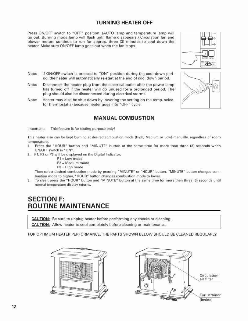
FOR OPTIMUM HEATER PERFORMANCE, THE PARTS SHOWN BELOW SHOULD BE CLEANED REGULARLY:
CAUTION: Be sure to unplug heater before performing any checks or cleaning.
CAUTION: Allow heater to cool completely before cleaning or maintenance.
TURNING HEATER OFF
MANUAL COMBUSTION
Press ON/OFF switch to “OFF” position. (AUTO lamp and temperature lamp will go out. Burning mode lamp will flash until flame disappears.) Circulation fan and blower motors continue to run for approx. three (3) minutes to cool down the heater. Make sure ON/OFF lamp goes out when the fan stops.
Note: If ON/OFF switch is pressed to “ON” position during the cool down peri-od, the heater will automatically re-start at the end of cool down period.
Note: Disconnect the heater plug from the electrical outlet after the power lamp has turned off if the heater will go unused for a prolonged period. The plug should also be disconnected during electrical storms.
Note: Heater may also be shut down by lowering the setting on the temp. selec-tor thermostat(s) because heater goes into “OFF” cycle.
SECTION F:ROUTINE MAINTENANCE
Important: This feature is for testing purpose only!
This heater also can be kept burning at desired combustion mode (High, Medium or Low) manually, regardless of room temperature.1. Press the “HOUR“ button and “MINUTE“ button at the same time for more than three (3) seconds when
ON/OFF switch is “ON“.2. P1, P2 or P3 will be displayed on the Digital Indicator;
P1 = Low modeP2 = Medium modeP3 = High mode
Then select desired combustion mode by pressing “MINUTE“ or “HOUR“ button. “MINUTE“ button changes com-bustion mode to higher, “HOUR“ button changes combustion mode to lower.
3. To clear, press the “HOUR“ button and “MINUTE“ button at the same time for more than three (3) seconds until normal temperature display returns.
BURNER
(NORMAL POSITION)
CLOCK SET
CLOCK / TEMP
STARTSET-BACK
50
10
70
21
90 F
32ºC
END SET-BACK
AUTO
Circulationair filter
Furl strainer(inside)
12

1. Clean Louvers (ONCE A WEEK)
Dust and stains should be wiped off louvers with a damp cloth.
2. Clean Circulation Fan Cover (ONCE A WEEK)
Remove only dust or pet hair from the cover on the back of the heater.
3. Check for Kerosene Leaks (REGULARLY)
Make it a habit to check for any sign of kerosene leakage along the fuel line and at all joints. Kerosene leaks may lead to risk of fire.
4. Check Flue Pipe Area (ONCE A WEEK)
Check the flue pipe joint to make sure connection is firm. Use a vacuum cleaner to remove any dust or pet hair.
5. Clean Fuel Strainer (ONCE A MONTH)
The strainer of the fuel sump should be cleaned once a month and before storing heater at the end of each season.
(a) Close the valve(s) of the separate fuel tank.
(b) To catch the fuel which will drain out, set the oil catch below the strainer
cover, with a small container under it.
(c) Loosen the two screws from the strainer cover and remove.
(d) Remove the strainer and wash with kerosene.
(e) Return the strainer to its original position. Replace strainer cover and
screw to secure.
(f) Wipe away any spilled kerosene.
(g) Open the valve(s) of separate fuel tank. Check for kerosene leakage.
Note: Be sure to unscrew the drain screw to remove all remaining kerosene from the fuel sump at the end of each season.
Check
Oil catch
FuelStrainer
Check
13

The following symptoms are normal during operation of the heater.
White smoke or smell at initial use afterpurchase.
Flames flashing for a few minutes afterignition.
Occasionally makes “cracking” noise whenheater is ignited or extinguished.
Part of the heat chamber or the heatexchanger is heated to a cherry red color.
Warm air will not blow as soon as ignited.
Audible chugging sound from fuel pumpwhen started first time or after running outof fuel.
“Ticking” noise.
Machine oil or dust burns of the surfaces ofthe burner or heat exchanger.
The burner is cold and igniter is kept runningfor a while after ignition.
Expansion and shrinkage of metal parts whenthey are heated or cooled.
To prevent uncomfortable cool air fromcoming out at the beginning, circulation fanstart up is delayed.
Air is in the pump. However, noise shouldstop within 1 minute.*
Noise of fuel pump in operation.Normal.
Normal.
Occasional yellow flickering in blue flame. Normal.
Wh
en h
eate
r is
sta
rted
or
exti
ng
uis
hed
.W
hen
hea
ter
isin
op
erat
ion
.
CONDITION REASON
SECTION G:TROUBLESHOOTING
NOTE BEFORE REQUESTING FOR REPAIR AND SERVICES
AUTOMATIC CLEANING SYSTEM
Heater will automatically clean igniter for ten (10) minutes every day at 2:00 a.m. and display “CL:10” on Digital Indicator if heater is running at that time.
MANUAL CLEANING SYSTEM
Heater will clean igniter for ten (10) minutes manually.
1. Press the “HOUR” button and “MINUTE” button at the same time for more than three (3) seconds when ON/OFF switch is “OFF”.
2. Display will appear “CL:10” on Digital Indicator. Cleaning will begin and end without any additional input.
Note: Cleaning igniter is important to prolong igniter life. It is recommended that the igniter be cleaned once a week.
*If sound from fuel pump does not decrease and heater shuts off, check:1. Push red reset button on fuel sump. DO NOT hold down.2. Insure that all valves are open and filter is clear.3. Insure external fuel tank has fuel and filters are clean.
14
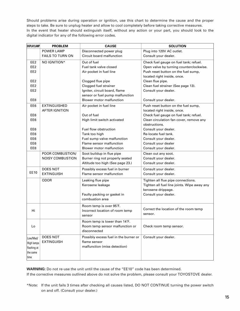
PROBLEMDISPLAY/LAMP CAUSE SOLUTION
POWER LAMPFAILS TO TURN ON
Disconnected power plugCircuit board malfunction
Plug into 120V AC outlet.Consult your dealer.
EE2EE2EE2
EE2EE2EE2
EE8
NO IGNITION* Out of fuelFuel tank valve closedAir pocket in fuel line
Clogged flue pipeClogged fuel strainerIgniter, circuit board, flamesensor or fuel pump malfunctionBlower motor malfunction
Check fuel gauge on fuel tank; refuel.Open valve by turning counterclockwise.Push reset button on the fuel sump,located right inside, once.Clean flue pipe.Clean fuel strainer (See page 13).Consult your dealer.
Consult your dealer.
EE6
EE6EE6
EE6EE6EE6EE6EE8
EXTINGUISHEDAFTER IGNITION
Air pocket in fuel line
Out of fuelHigh limit switch activated
Fuel flow obstructionTank too highFuel sump valve malfunctionFlame sensor malfunctionBlower motor malfunction
Push reset button on the fuel sump,located right inside, once.Check fuel gauge on fuel tank; refuel.Clean circulation fan cover, remove any obstructions.Consult your dealer.Re-locate fuel tank.Consult your dealer.Consult your dealerConsult your dealer.
POOR COMBUSTION/NOISY COMBUSTION
Soot buildup in flue pipeBurner ring not properly seatedAltitude too high (See page 23.)
Clean out any soot.Consult your dealer.Consult your dealer.
EE10DOES NOTEXTINGUISH
Possibly excess fuel in burnerFlame sensor malfunction
Consult your dealer.Consult your dealer.
ODOR Leaking flue pipeKerosene leakage
Faulty packing or gasket in combustion area
Tighten all flue pipe connections.Tighten all fuel line joints. Wipe away any kerosene drippage.Consult your dealer.
HiRoom temp is over 95˚F.Incorrect location of room temp sensor
Correct the location of the room temp sensor.
LoRoom temp is lower than 14˚F.Room temp sensor malfunction or disconnected
Check room temp sensor.
Low/Med/High lamps flashing at the same time
DOES NOTEXTINGUISH
Possibly excess fuel in the burner or flame sensormalfunction (miss detection)
Consult your dealer.
Should problems arise during operation or ignition, use this chart to determine the cause and the proper steps to take. Be sure to unplug heater and allow to cool completely before taking corrective measures.In the event that heater should extinguish itself, without any action or your part, you should look to the digital indicator for any of the following error codes.
WARNING: Do not re-use the unit until the cause of the “EE10” code has been determined.If the corrective measures outlined above do not solve the problem, please consult your TOYOSTOVE dealer.
*Note: If the unit fails 3 times after checking all causes listed, DO NOT CONTINUE turning the power switch on and off. (Consult your dealer.)
15

At the close of each heating season, or when you do not plan to use your heater for an extended period, the following procedures are recommended.
1. As the end of the season approaches, calculate your kerosene purchases so that you can use up all the kerosene you have on hand. When kerosene is stored for over six months, its quality may deteriorate. The use of such kerosene will have an unfavorable effect on heater operation.
2. If your heater needs any service or repair, now is the time to call your dealer and get it done before storage. That way your heater will be ready for immediate use when the next heating season begins.
3. If you plan to store your heater in place,
(a) Disconnect power supply.
(b) Close the main tank valve.
(c) Remove all kerosene from the fuel sump and clean the fuel strainer.(See page 13.)
(d) Wipe off any stains or dust on heater with a damp cloth, then wipe once again using a dry cloth.
(e) Cover heater completely with a large plastic bag to protect from dust.
SECTION H:LONG TERM STORAGE
16

Pipe Holder (1) (PART #20474963)
Wall Brackets (2 sets) (PART #20474962)
Pipe Stopper (1) (PART #20474964)
Drip Tray (1) (PART #20479929)
SECTION I:INSTALLATION
TOOLS NEEDED FOR INSTALLATION
STANDARD INSTALLATION PARTS
The following standard installation parts are enclosed with heater. For alternate installation methods, you may need to purchase additional accessories which are available from your TOYOSTOVE dealer. See ”Accessory Parts“, page 19.
Tool Use
Phillips Head Screwdriver Installation of flue pipe, etc.Electric Drill Drilling hole in wall for flue pipeHole Saw, 2-3/4 to 3“ diameter Making hole in wall for flue pipe
17

Flue Pipe (1) (PART #20479891)Exhaust Air Cap (1) (PART #20479845)Intake Air Cap (1) (PART #20474949)
Oil Catch (1) (PART #20474925)
Inlet Hose (1) (PART #20474951)
Spacer (1) (PART #20478967)
Bent Joint (1) (PART #20474984) L-Shaped Hose (2) (PART #20474975)
Hose Band (2) (PART #20474977)
(3)(3)
18

Fuel Lifter Pump Model OPT-91UL
PART #20477500
PART #20479872
PART #20474951
PART #20474950
PART #20479861
PART #20474955PART #20474954
Exhaust Extension Pipe
PART #20479887
1035
Intake PipeJoint
Insulating cloth cover
Pipe SupportHardware
L-Shaped exhaust joint
Intake Pipe
FUELLIFTER PUMPLOCATIONEXAMPLE
FUELTANK
FUELTANK
FUELLIFTER PUMPLOCATIONEXAMPLE
PART #20479853
Adjustable Exhaust PipeMax. 39-3/8 ~ Min. 22-7/16
10 10 35
PART #20479887 Flue pipe ext. (for wall up to "9~13")PART #20479873 Flue pipe ext. (for wall up to "13~16")PART #20479874 Flue pipe ext. (for wall up to "16~20")PART #20479875 Flue pipe ext. (for wall up to "20~24")
Flue pipe extension
External Fuel SupplyInstallation Kit
PART# 10005098
40 inch3-1/2
6-1/2 ft.
39-3/8
3-1/2
3-3 /
8
ACCESSORY PARTS
The following accessory parts are available for use in non-standard installation of the Laser 60AT. After giving careful consideration to your desired heater and flue pipe locations and fueling system, consult your TOYOSTOVE dealer to purchase the necessary accessory parts.Important: Use only genuine TOYOSTOVE parts for your heater. Use of unauthorized generic or other
brand parts can severely reduce performance and safety, and will invalidate factory warranty.
Accessory
Extension pipe kit (L)*
Extension pipe kit (M)*
Extension pipe kit (S)*
L-Shaped exhaust joint*
Fuel lifter pumpModel OPT-91UL
Window Kit (L)
Window Kit (S)
External Fuel SupplyInstallation Kit
Part No.
20479898
20479897
20479896
20479861
20477500
20475589
20475588
10005098
Application
Extends pipe system by 61-3/4 to 78-3/4”
Extends pipe system by 22-1/2 to 39-3/8”
Extends pipe system by 12-5/8 to 19-5/8”
For 90 degree bend in exhaust pipe
Used to lift fuel to heater when fuel tank is located underground or outdoors in a position lower than the heater.With automatic recovery. (Not available in Canada)
For installation of flue pipe in windowsfrom 31 to 50 inches wide. (Not available in Canada)
For installation of flue pipe in windowsfrom 20 to 32 inches wide. (Not available in Canada)
For installation of external tank system
* Total length of extension pipe between heater and flue pipe must be no greater than 10 ft. No more than three bends may be used in extension pipe.
19
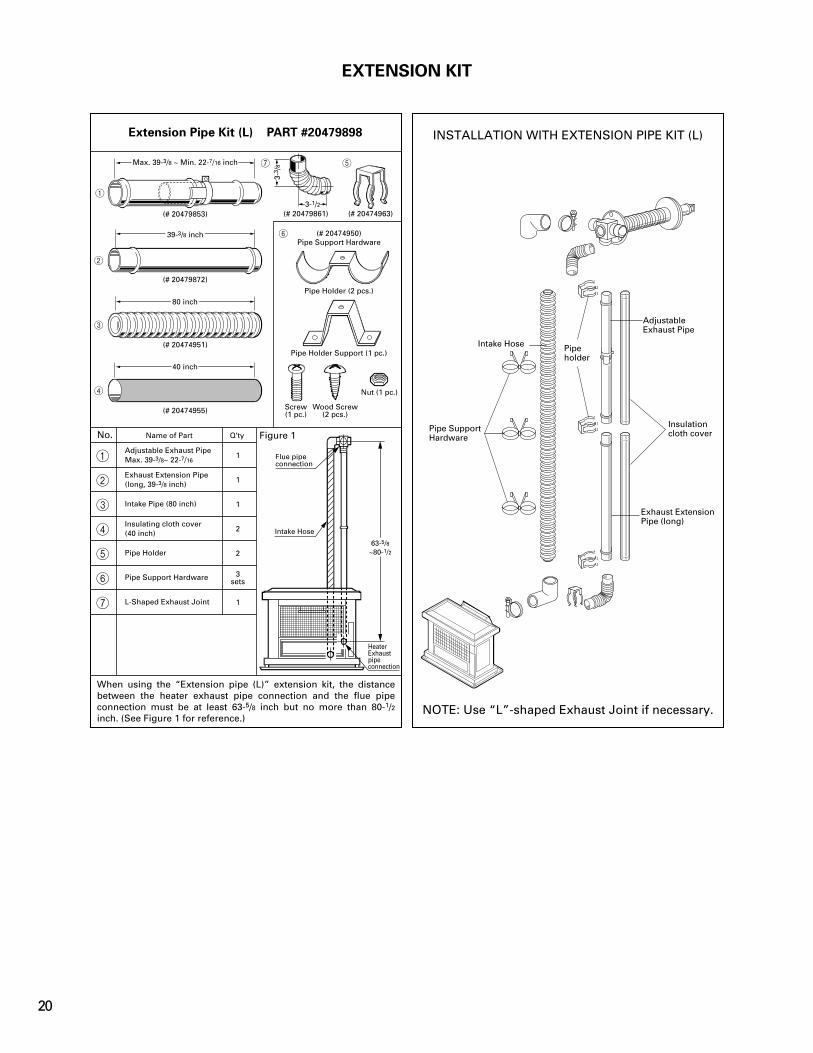
EXTENSION KIT
When using the “Extension pipe (L)” extension kit, the distance between the heater exhaust pipe connection and the flue pipe connection must be at least 63-5/8 inch but no more than 80-1/2 inch. (See Figure 1 for reference.)
Extension Pipe Kit (L) PART #20479898
No. Name of Part Q’ty
1
2
3
4
5
6
7
Adjustable Exhaust PipeMax. 39-3/8~ 22-7/16
Exhaust Extension Pipe(long, 39-3/8 inch)
Intake Pipe (80 inch)
Insulating cloth cover(40 inch)
Pipe Holder
Pipe Support Hardware
L-Shaped Exhaust Joint
1
1
1
2
2
3sets
1
NOTE: Use “L”-shaped Exhaust Joint if necessary.
INSTALLATION WITH EXTENSION PIPE KIT (L)
AdjustableExhaust Pipe
Insulationcloth cover
Exhaust ExtensionPipe (long)
Pipeholder
Intake Hose
Pipe SupportHardware
(# 20479861) (# 20474963)
(# 20474950)
(# 20479853)
(# 20479872)
(# 20474951)
(# 20474955)
Pipe Support Hardware
Pipe Holder (2 pcs.)
Pipe Holder Support (1 pc.)
Screw(1 pc.)
Wood Screw(2 pcs.)
Nut (1 pc.)
7 5
6
3-3 /
8
3-1/21
2
3
4
40 inch
80 inch
39-3/8 inch
Max. 39-3/8 ~ Min. 22-7/16 inch
Figure 1
HeaterExhaustpipeconnection
Flue pipe connection
Intake Hose
63-5/8~80-1/2
20

When using the “Extension pipe (M)” extension kit, the distance between the heater exhaust pipe connection and the flue pipe connection must be at least 25-5/8 inch but no more than 42-1/2 inch. (See Figure 2 for reference.)
Extension Pipe Kit (M) PART #20479897
No. Name of Part Q’ty
1
2
3
4
5
6
Adjustable Exhaust PipeMax. 39-3/8~ Min. 22-7/16
Intake Pipe (40 inch)
Insulating cloth cover(40 inch)
Pipe Holder
Pipe Support Hardware
L-Shaped Exhaust Joint
1
1
1
1
2sets
1
When using the “Extension pipe (S)” extension kit, the distance between the heater exhaust pipe connection and the flue pipe connection must be at least 15-3/4 inch but no more than 22-3/4 inch. (See Figure 3 for reference.)
Extension Pipe Kit (S) PART #20479896
No. Name of Part Q’ty
1
2
3
4
5
6
Adjustable Exhaust PipeMax. 19-11/16~ Min. 12-5/8
Intake Pipe (20 inch)
Insulating cloth cover(40 inch)
Pipe Holder
Pipe Support Hardware
L-Shaped Exhaust Joint
1
1
1
1
1sets
1
(# 20479861) (# 20474963)
(# 20474950)(# 20479853)
(# 20474951)
(# 20474955)
Pipe Support Hardware
Pipe Holder (2 pcs.)
Pipe Holder Support (1 pc.)
Screw(1 pc.)
Wood Screw(2 pcs.)
Nut (1 pc.)
6 4
5
3-3 /
8
3-1/2(# 20479861) (# 20474963)
(# 20474950)Pipe Support Hardware
Pipe Holder (2 pcs.)
Pipe Holder Support (1 pc.)
Screw(1 pc.)
Wood Screw(2 pcs.)
Nut (1 pc.)
6 4
5
3-3 /
8
3-1/21
2
3
Max. 39-3/8 ~ Min. 22-7/16 inch
40 inch
40 inch
(# 20479858)
(# 20474951)
(# 20474955)
6
1
2
3
Max. 19-11/16 ~ Min. 12-5/8 inch
20 inch
40 inch
Figure 2 Figure 3
Window Kit (L) PART #20475589 (31-50 inches)
Window Kit (S) PART #20475588 (20-32 inches)
Ex. Window Kit
WINDOW KIT
Flue pipe connection
Intake Hose
HeaterExhaustpipeconnection
Flue pipe connection
Intake Hose
HeaterExhaustpipeconnection
25-5/8~42-1/2
15-3/4~ 22-3/4
21
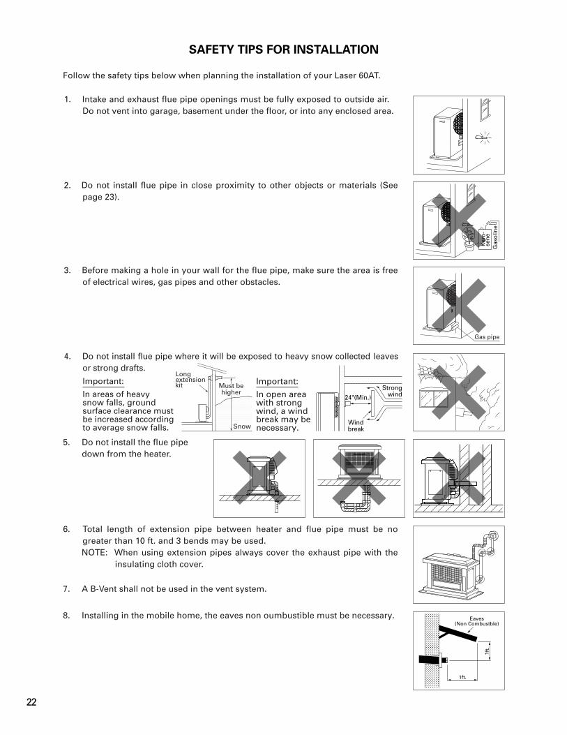
SAFETY TIPS FOR INSTALLATION
Important:
In areas of heavysnow falls, ground surface clearance must be increased according to average snow falls.
Important:
In open area with strong wind, a wind break may be necessary.
Follow the safety tips below when planning the installation of your Laser 60AT.
1. Intake and exhaust flue pipe openings must be fully exposed to outside air. Do not vent into garage, basement under the floor, or into any enclosed area.
2. Do not install flue pipe in close proximity to other objects or materials (See page 23).
3. Before making a hole in your wall for the flue pipe, make sure the area is free of electrical wires, gas pipes and other obstacles.
4. Do not install flue pipe where it will be exposed to heavy snow collected leaves or strong drafts.
5. Do not install the flue pipedown from the heater.
6. Total length of extension pipe between heater and flue pipe must be no greater than 10 ft. and 3 bends may be used.NOTE: When using extension pipes always cover the exhaust pipe with the
insulating cloth cover.
7. A B-Vent shall not be used in the vent system.
8. Installing in the mobile home, the eaves non oumbustible must be necessary.
1ft.
Eaves(Non Combustble)
1ft.
Longextensionkit
SnowSnow
Must behigher
24"(Min.)
Windbreak
Strongwind
Gas
olin
e
Ker
o-
sen
e
Gas pipe
22
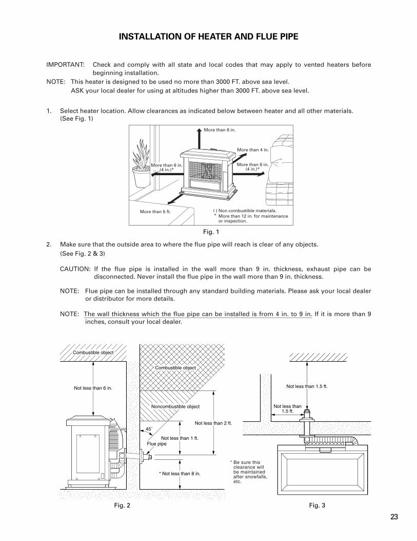
INSTALLATION OF HEATER AND FLUE PIPE
IMPORTANT: Check and comply with all state and local codes that may apply to vented heaters before beginning installation.
NOTE: This heater is designed to be used no more than 3000 FT. above sea level.ASK your local dealer for using at altitudes higher than 3000 FT. above sea level.
Fig. 1
1. Select heater location. Allow clearances as indicated below between heater and all other materials.(See Fig. 1)
2. Make sure that the outside area to where the flue pipe will reach is clear of any objects.(See Fig. 2 & 3)
CAUTION: If the flue pipe is installed in the wall more than 9 in. thickness, exhaust pipe can be disconnected. Never install the flue pipe in the wall more than 9 in. thickness.
NOTE: Flue pipe can be installed through any standard building materials. Please ask your local dealer or distributor for more details.
NOTE: The wall thickness which the flue pipe can be installed is from 4 in. to 9 in. If it is more than 9 inches, consult your local dealer.
More than 5 ft. Non combustible materials.More than 12 in. for maintenanceor inspection.
( )*
More than 6 in.
More than 6 in.(4 in.)*
More than 4 in.
More than 6 in.(4 in.)*
Combustible object
Not less than 6 in.
Combustible object
Noncombustible object
Not less than 2 ft.
Not less than 1 ft.Flue pipe
* Not less than 8 in.
45˚
* Be sure thisclearance willbe maintainedafter snowfalls,etc.
Fig. 2 Fig. 3
Not less than1.5 ft.
Not less than 1.5 ft.
23

3. Install the ceramic log.
a. Remove four (4) screws from top plate and remove the top plate.
b. Remove four (4) screws from canopy guard and remove the canopy guard. Remove the heat chamber lid from the heat exchanger.
c. Gently insert the ceramic logs into three (3) brackets inside of burner properly. After inserting the ceramic logs, install log supporter on the upper holes of the ceramic logs. Adjust the log supporter so as to place the logs at the center of the burner.
Log supporter
Canopy guard
Top View
<Heat Chamber Lid>
WrongCorrect
<Canopy Guard>
24
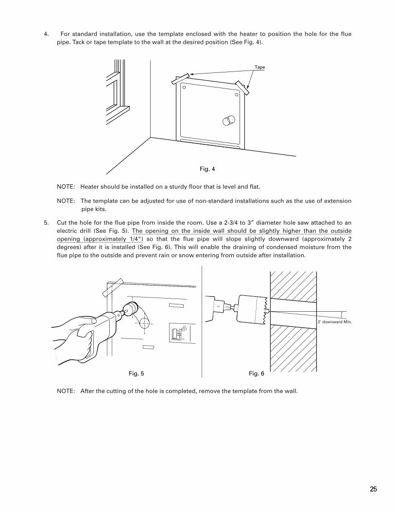
Fig. 4
4. For standard installation, use the template enclosed with the heater to position the hole for the flue pipe. Tack or tape template to the wall at the desired position (See Fig. 4).
NOTE: Heater should be installed on a sturdy floor that is level and flat.
NOTE: The template can be adjusted for use of non-standard installations such as the use of extension pipe kits.
5. Cut the hole for the flue pipe from inside the room. Use a 2-3/4 to 3” diameter hole saw attached to an electric drill (See Fig. 5). The opening on the inside wall should be slightly higher than the outside opening (approximately 1/4“) so that the flue pipe will slope slightly downward (approximately 2 degrees) after it is installed (See Fig. 6). This will enable the draining of condensed moisture from the flue pipe to the outside and prevent rain or snow entering from outside after installation.
NOTE: After the cutting of the hole is completed, remove the template from the wall.
Tape
2˚ downward Min.
Fig. 5 Fig. 6
25
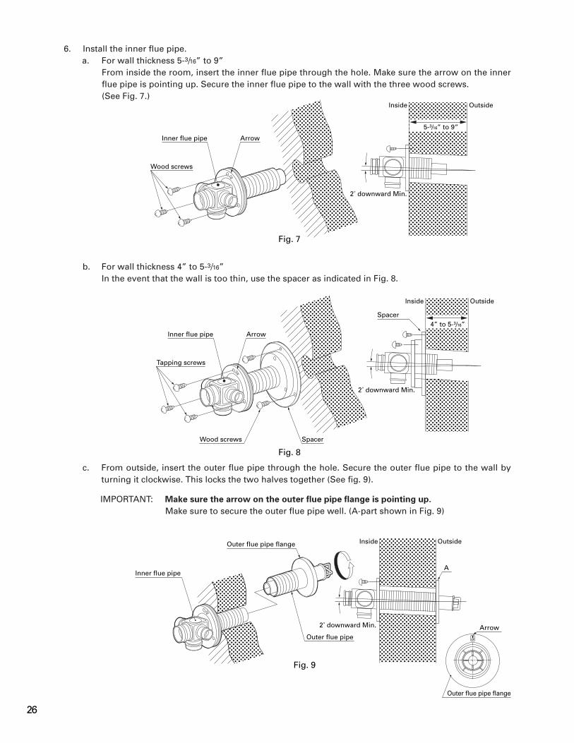
6. Install the inner flue pipe.a. For wall thickness 5-3/16” to 9”
From inside the room, insert the inner flue pipe through the hole. Make sure the arrow on the inner flue pipe is pointing up. Secure the inner flue pipe to the wall with the three wood screws.(See Fig. 7.)
b. For wall thickness 4” to 5-3/16”In the event that the wall is too thin, use the spacer as indicated in Fig. 8.
c. From outside, insert the outer flue pipe through the hole. Secure the outer flue pipe to the wall by turning it clockwise. This locks the two halves together (See fig. 9).
IMPORTANT: Make sure the arrow on the outer flue pipe flange is pointing up.
Make sure to secure the outer flue pipe well. (A-part shown in Fig. 9)
Inner flue pipe
Wood screws
Arrow
Inside Outside
5-3/16” to 9”
2˚ downward Min.
Fig. 7
Inner flue pipe
Wood screws
Arrow
Inside Outside
4” to 5-3/16”
2˚ downward Min.
Spacer
Tapping screws
Spacer
Fig. 8
Inner flue pipe
Inside Outside
Arrow2˚ downward Min.
Outer flue pipe flange
A
Outer flue pipe
Outer flue pipe flange
Fig. 9
26

7. Insert the bent joint to the exhaust mouth of the flue pipe. Cut the inlet hose for desired length if necessary. Attach the L-shaped hose to each end of the inlet hose and attach the L-shaped hose to the intake mouth of the flue pipe. Secure the L-shaped hose to the intake mouth with the hose band. Plug the unused exhaust and intake mouth with the caps provided with the heater. Make sure the caps fit tightly onto the mouth (See Fig. 10).
NOTE: If the inlet hose is not smoothly inserted into the L-shaped hose, apply water or soap suds to the inlet hose.
8. Move the heater into position. Connect the bent joint to the exhaust outlet mouth (upper opening) and attach the L-shaped hose to the intake inlet mouth. Make sure all connections are tight (See Fig. 11).
Fig. 10
Fig. 11
Outlet Mouth
Inlet Mouth L-Shaped Hose
Bent Joint
L-Shaped Hose
Hose Band
Exhaust Air Cap
Intake Air Cap
Exhaust Mouth
Bent Joint
Inlet Hose
27

Fig. 14
Fig. 12
9. Secure the L-shaped hose to the intake inlet mouth with the hose band. Secure the bent joint to the flue pipe with the pipe holder (If the extension pipe is used, also attach the pipe holder to the connection of the bent joint and the extension pipe). Secure the bent joint (or the extension pipe) to the exhaust outlet mouth by sliding the pipe stopper in the exhaust mouth bracket (See Fig. 12).
10.� Make sure the position of the heater is level by using the plumb bob located at the right side of the heater. The plumb bob weight should be within the circle. If the plumb bob weight is not within the circle, adjust the heater legs until the plumb bob weight is within the red circle (See Fig. 13 & 14).
Plumb bob as viewed from above
Fig. 13
Pipe holder
Pipe Stopper
Good
Bad
Circle
Weight
28

Fig. 15
11. A room temperature sensor is provided with an eight (8) feet long extension wire. It is located on the rear of the cabinet. Make sure that the extension wire is not touching the exhaust pipe. The room tem-perature sensor can be installed either with the self adhesive tape on the back or with a wood screw provided with the sensor depending on the type of surface chosen for installation.NOTE: Choose a location for the sensor that is not in the path of direct sunlight, drafts or the flow of
warm air from the heater.
(a) Self Adhesive TapePeel off the protective tape on the back of the sensor and expose the adhesives. Place the sensor on the desired location on the wall and press down.
(b) Wood ScrewScrew down the wood screw provided with the heater into the desired location on the wall. Hook the back of the room temperature sensor.
12. After installation is completed, secure heater to the wall with the wall brackets provided with the heater. Make sure the heater is parallel to the wall (See Fig. 15).
13. Before ignition, recheck the following:a. All connections are tight and firm.b. The heater and the flue pipe areas are free of any materials.c. The heater is level and parallel to the wall.
29
SECTION J:FUELING
WARNING: Use only clear or red dyed ASTM D3699 1-K Kerosene. NEVER USE GASOLINE.
Use of gasoline can lead to uncontrollable flames resulting in destructive fire.
Laser 60AT FUEL SYSTEM OPTIONS
¡ Large Capacity External TankTank must be purchased separately and installed by a qualified fuel supply technician.
EXTERNAL TANK INSTALLATION
NOTE: External tank installation must comply with National Fire Protection Association Code NFPA 31, CSA Standard B139, the Installation Code for Oil Burning Equipment, or locally applicable codes. Check with local building officials.
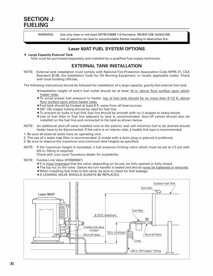
The following instructions should be followed for installation of a large capacity, gravity-fed external fuel tank.
¡Installation height of tank's fuel outlet should be at least 16 in. above floor surface upon which heater rests.
¡To avoid excess fuel pressure to heater, top of fuel tank should be no more than 8-1/2 ft. above floor surface upon which heater rests.
¡Fuel tank should be located at least 6 ft. away from all heat sources.¡3/8” OD copper tubing should be used for fuel line.¡To prevent air locks in fuel line, fuel line should be smooth with no U-shaped or sharp bends.¡Use of fuel filter in fuel line adjacent to tank is recommended, shut-off valves should also be
installed on the fuel line and connected to the tank as shown below.
NOTE: An additional shut-off valve installed next to the exterior wall will minimize fuel to be drained should heater have to be disconnected. If the valve is on interior side, a fusible link type is recommended.
1. Be sure all external tanks have an operating vent.2. The use of a water trap filter is recommended. A model with a drain plug or petcock is preferred.3. Be sure to observe the maximum and minimum tank heights as specified.
NOTE: If the maximum height is exceeded, a fuel pressure limiting valve which must be set at 2.5 psi with 3/8-in. fitting is required.Check with your local Toyostove dealer for availability.
NOTE: Fusible Link Valve (#10005597)¡It is most important that the valve, depending on its use, be fully opened or fully closed.¡The top nut on the valve (below the turn handle) is sealed and should never be tightened or removed.¡When installing fuel lines to the valve, be sure to check for fuel leakage.¡A LEAKING VALVE SHOULD ALWAYS BE REPLACED.
Laser 60AT
Fuel filter
8-1/2 ft. maximum
16 in. minimum
Tank Vent
Outdoor Fuel Tank
Shut-off Valve
Loop
3/8 in. OD Copper Tubing
Shut-off Valve
Fusible link valve(inside)
30

31

Rev. 2/05
Part #20479995 Printed in Japan
TOYOTOMI U.S.A., INC.604 Federal Road, Brookfield, CT 06804
www.toyotomiusa.com
TOYOTOMI U.S.A., INC.("TOYOTOMI") warrants each product and any parts thereof sold by it to be free from defects in materials or workmanship under normal use and service for TWELVE (12) MONTHS* from the date of delivery to the original purchaser at retail subject to the following terms and conditions :
WHAT IS COVERED : Product or any parts thereof which are defective in materials of workmanship.
WHAT IS NOT COVERED :(1) This warranty does not extend to any defect due to the negligence of others: failure to install, operate, or maintain unit in accordance with instructions (Installation and Operation instructions are furnished with each new unit); unreasonable use; accidents; alteration, use of unauthorized or non-standardized TOYOTOMI parts and accessories; electrical malfunction, i.e., as resulting from large power surges, short circuit, etc.; incorrect installation; use of any fuel other than that specified in owner's manuals; or repair by anyone other than a service facility specified by TOYOTOMI.(2) Normal wear and tear of parts, including hoses, wires, burner mats, fuel nozzles, filters and accessories.(3) This warranty does not cover shipping costs.
WHO IS COVERED : The original purchaser at retail.
WHAT WE WILL DO : TOYOTOMI will either repair or replace, at its option, all defective parts free of charge that are covered by this limited warranty on a carry-in basis, to your nearest authorized dealer or distributor of TOYOTOMI.
WHAT YOU MUST DO FOR WARRANTY SERVICE : You must return the defective Product or part to any authorized dealer or distributor of TOYOTOMI with this LIMITED WARRANTY and a copy of your bill of sale or credit card charge receipt or other documents evidencing the date of the Product's delivery, if service is not available locally, please contact our CUSTOMER RELATIONS DEPARTMENT at :
TOYOTOMI U.S.A., INC.604 Federal Road, Brookfield, CT 06804
(203)775-1909
THE FOREGOING EXPRESSES ALL OF TOYOTOMI'S OBLIGATIONS AND LIABILITIES WITH RESPECT TO THE QUALITY OF PRODUCT FURNISHED BY IT. ALL OTHER WARRANTIES, EXPRESSED OR IMPLIED, INCLUDING THE WARRANTIES OF MERCHANTABILITY OR FITNESS FOR A PARTICULAR PURPOSE ARE DISCLAIMED. TOYOTOMI SHALL NOT BE LIABLE FOR THE LOSS OF USE OF THE PRODUCT, INCONVENIENCE, LOSS OR ANY OTHER DAMAGES, DIRECT OR CONSEQUENTIAL ARISING OUT OF, THE USE OF, OR INABILITY TO USE, THE PRODUCT OR DAMAGES RESULTING FROM OR ATTRIBUTABLE TO DEFECTS IN THE PRODUCT.
No one other than TOYOTOMI has authority to extend or modify the terms of this Limited Warranty in any manner whatsoever.
Some states or provinces do not allow the exclusion or limitation of incidental or consequential damages or limitations on how long an implied warranty lasts, so these limitations or exclusions may not apply to you. This Limited Warranty gives you specific legal rights and you may also have other rights that vary from state to state, or province to province.
* In addition to the warranty period stated above, an extended two (2) year warranty (3 years from date of purchase) is on for the following parts. :
1.Vented Heater :A. Burner PotB. Heat Chamber (Excluding Glass Cylinder)C. Heat Exchanger
2.Hot Water Heater :A. Burner TopB. Heat Exchanger
NOTE : THE EXTENDED WARRANTY POLICY IS APPLICABLE ONLY FOR THE REPLACEMENT OF THE ORIGINAL FACTORY-INSTALLED PARTS THAT HAVE FAILED WITHIN THE TIME LIMITATIONS AS INDICATED. REPLACEMENT PARTS ARE WARRANTED FOR THE REMAINDER OF THE ORIGINAL PART WARRANTY PERIOD. LABOR IS NOT COVERED ON THE EXTENDED WARRANTY.
7104002060
LIMITED WARRANTY