laser systems grindline - imajteknik.net · designed for on-line gauging of the outside diameter of...
TRANSCRIPT

The Grindline.X Laser System has been specially designed for on-line gauging of the outside diameter of products manufactured by through-feed centreless grinding machines, like pins, shock absorbers rods, steering racks or any other part having one ground diameter only to be checked.
The main functions of the system are as follows:
• through-feed measurement and display of the ground diameter
• tolerance checking and output alarms for part sorting
• real-time grinder regulation
• processing and printing of statistical reports
• interface with remote computer
• NO-VAR technology: no measuring drift due to changing room temperature
GRINDLINE.XLaser System for through-feed, single diameter measuring and grinder regulation.
™™
Laser Systems ™
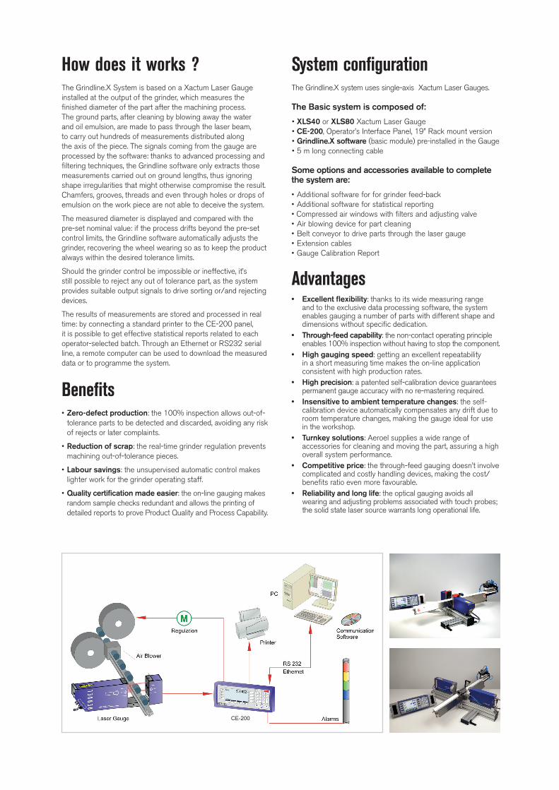
How does it works ?The Grindline.X System is based on a Xactum Laser Gauge installed at the output of the grinder, which measures the finished diameter of the part after the machining process. The ground parts, after cleaning by blowing away the water and oil emulsion, are made to pass through the laser beam, to carry out hundreds of measurements distributed along the axis of the piece. The signals coming from the gauge are processed by the software: thanks to advanced processing and filtering techniques, the Grindline software only extracts those measurements carried out on ground lengths, thus ignoring shape irregularities that might otherwise compromise the result. Chamfers, grooves, threads and even through holes or drops of emulsion on the work piece are not able to deceive the system.
The measured diameter is displayed and compared with the pre-set nominal value: if the process drifts beyond the pre-set control limits, the Grindline software automatically adjusts the grinder, recovering the wheel wearing so as to keep the product always within the desired tolerance limits.
Should the grinder control be impossible or ineffective, it’s still possible to reject any out of tolerance part, as the system provides suitable output signals to drive sorting or/and rejecting devices.
The results of measurements are stored and processed in real time: by connecting a standard printer to the CE-200 panel, it is possible to get effective statistical reports related to each operator-selected batch. Through an Ethernet or RS232 serial line, a remote computer can be used to download the measured data or to programme the system.
Benefits• Zero-defect production: the 100% inspection allows out-of-
tolerance parts to be detected and discarded, avoiding any risk of rejects or later complaints.
• Reduction of scrap: the real-time grinder regulation prevents machining out-of-tolerance pieces.
• Labour savings: the unsupervised automatic control makes lighter work for the grinder operating staff.
• Quality certification made easier: the on-line gauging makes random sample checks redundant and allows the printing of detailed reports to prove Product Quality and Process Capability.
System configurationThe Grindline.X system uses single-axis Xactum Laser Gauges.
The Basic system is composed of:
• XLS40 or XLS80 Xactum Laser Gauge• CE-200, Operator’s Interface Panel, 19” Rack mount version• Grindline.X software (basic module) pre-installed in the Gauge• 5 m long connecting cable
Some options and accessories available to complete the system are:
• Additional software for for grinder feed-back• Additional software for statistical reporting• Compressed air windows with filters and adjusting valve• Air blowing device for part cleaning• Belt conveyor to drive parts through the laser gauge• Extension cables• Gauge Calibration Report
Advantages• Excellent flexibility: thanks to its wide measuring range
and to the exclusive data processing software, the system enables gauging a number of parts with different shape and dimensions without specific dedication.
• Through-feed capability: the non-contact operating principle enables 100% inspection without having to stop the component.
• High gauging speed: getting an excellent repeatability in a short measuring time makes the on-line application consistent with high production rates.
• High precision: a patented self-calibration device guarantees permanent gauge accuracy with no re-mastering required.
• Insensitive to ambient temperature changes: the self-calibration device automatically compensates any drift due to room temperature changes, making the gauge ideal for use in the workshop.
• Turnkey solutions: Aeroel supplies a wide range of accessories for cleaning and moving the part, assuring a high overall system performance.
• Competitive price: the through-feed gauging doesn’t involve complicated and costly handling devices, making the cost/benefits ratio even more favourable.
• Reliability and long life: the optical gauging avoids all wearing and adjusting problems associated with touch probes; the solid state laser source warrants long operational life.
CE-200

The Grindline.X Software The Grindline.X software is pre-loaded inside the Xactum gauge and, thanks to its modular structure (basic package + optional Regulation and Statistics) it can meet all operational requirements. Special care has been taken to ensure that the system is easy to use and simple to program even by non-experts. Through the CE-200 Interface Panel, the operator
uses function keys and pop-up menus to select the various functions or to enter the numerical values requested by the program.
The basic package includes the following functions:
• Display of the measured diameter and of the shift from the nominal diameter.
• 3 measured values can be simultaneously displayed on the screen.
• Automatic recognition of ground lengths and filtering of all shape irregularities.
• Selection of the transportation mode between “separate parts” or “pushing parts”.
• In “separate parts” mode the shape check (cylindrically) is possible and the software is also able to ignore non-axis-symmetrical irregularities like grooves or radial holes.
• Several consecutive parts can be included in the average, to improve measuring repeatability even at higher grinding rates.
• Nominal diameter and tolerance programming.
The additional Process Regulation module (Option 1) features the following functions:
• Software for automatic diameter regulation, by adjusting the distance between the grinding wheels.
• PI (Proportional-Integral) mode, using INC (+) or DEC (-) pulse trains, whose number is proportional to the amount of the required correction.
• Regulation is started after having positively checked a real trend to drift from the nominal set-point.
• Control parameters can be programmed and stored in the product library.
• Automatic backlash recovery, by adding extra pulses each time the correction is reversed.
• To avoid over-regulation, the control routine skips the already machined parts included between the gauge and the wheels.
• Additional input to hold regulation during diamond dressing of the grinding wheel.
The additional Statistics module (Option 2) offers the following functions:
• Processing and printing of a statistical report for each selected batch or order.
• Computing and listing of max, min, avg, Cp and Cpk values of each measured parameter (average diameter and shape error)
• The batch is manually selected by the operator, using the touch keys on the front panel of the CE-10 unit.
• Identification of the order, of nominal value, of tolerance range and counting of parts included in the selected batch.
• Statistics can include all the parts of the batch (good and rejected), or it can be restricted to the good parts only.
• All reports show the date and time
+------------------------------------------------------------------------------+ | 15:46 24/07/2007 | | | | JOB NOMINAL [mm] UPPER TOL.[mm] LOWER TOL.[mm] FORM ERROR[mm] | | 5 10.0030 0.0015 -0.0015 0.0010 | |------------------------------------------------------------------------------|
| [mm] [mm] [mm] [μm] | | 36 10.0013 10.0041 10.0053 0.760 0.66 0.18 | | |
| [mm] [mm] [mm] [μm] | | 0.0001 0.0007 0.0025 0.632 0.26 0.16 | |------------------------------------------------------------------------------|
| SAMPLES 36 19 17 | |------------------------------------------------------------------------------| | TESTED BY AEROEL - UDINE - ITALY | +------------------------------------------------------------------------------+
• Out-of-tolerance alarms (Go/NoGo) and delayed signals for part sorting (Reject/Rework)
• Signal for “unidentified piece” to discard abnormal parts, if any.
• Library of parameters for 1000 different products, directly retrievable by the operator.
• Possibility of entering a password to restrict the programming functions to authorized personnel.
• Ethernet / Rs232 interface for remote programming or data retrieval.
• Multi-lingual menus (Italian, English, French and German).• Selectable measuring unit (mm or inches) and resolution.• Pre-programmed factory set-up to facilitate installation and
start-up of the system.
NO-VAR option
• Automatic self-compensation of the part thermal expansion, by programming its thermal expansion coefficient. It requires a condition of thermal equilibrium between the gauge and the part being measured and a max. 3°C/hr rate of change of the ambient temperature
™™

790
XLS40 XLS80
All dimensions are in mm.
GRINDLINE X 40/A X 40/B X 80/A X 80/B
Type of gauge XLS40/1500/A XLS40/1500/B XLS80/1500/A XLS80/1500/B
Measuring Field (mm) 40 80
Measurable Diameters (mm) 0.1 ÷ 38 0.06 ÷ 38 0.75 ÷ 78
Resolution (Selectable) (μm) 10 / 1 / 0.1 / 0.01
Linearity (Centred Product) (μm) ± 0.5 (1) ± 1 (2)
Linearity (in the Measuring Plane) (3) (μm) ± 0.5 ± 2
Repeatability (T=1s, ±3 ) (μm) ± 0.1 ± 0.3
Single Shot Repeatability (±3 ) (μm) ± 2.5 ± 5
Beam Spot Size (s,l) (4) (mm) 0.08 x 2 0.06 x 0.1 0.4 x 3.5 0.4 x 0.2
Side Dither of the Scanning Plane (mm) ± 0.1 ± 0.2
Scanning Frequency (Hz) 1500
Scanning Speed (m/s) 300 588
Gauge Thermal Coefficient (5) (μm/m°C) - 11.5
Laser Source VLD (Visible Laser Diode); = 650 nm
Dimensions (mm) 500 x 134 x 68.5 787 x 170 x 60
Weight (kg) 4.2 7
Notes
(1) For Ø 25 mm. For 25 Ø 38 mm the linearity is ± 0.75 μm. The value is inclusive of the Aeroel’s masters uncertainty (± 0.3 μm )
(2) For Ø 40 mm. For 40 Ø 78 mm the linearity is ± 1.5 μm. The value is inclusive of the Aeroel’s masters uncertainty (± 0.3 μm )
(3) Maximum error, when a master is moved in the measuring plane, checked with Ø 8 mm (XLS40) or Ø 20 mm (XLS80). The measuring plane is located halfway between transmitter and receiver.
(4) Elliptical spot: “s” is the thickness and “l” is the width.(5) This is the measuring error due to a change in the ambient temperature when
measuring a part with zero thermal expansion coefficient (INVAR). This is specified for gauges using a software PRESET for the NO-VAR option and when the rate of change of the ambient temperature is lower than 3°/h. When the NO-VAR option is ENABLED, the gauge thermal expansion coefficient is programmable by the user.
Specifications
Specifications subject to change without notice. For additional details and complete specifications please see the gauge data sheet.
AEROEL SRL - Via Pier Paolo Pasolini, 35/3 - 33040 Pradamano (UD) ITALY - tel. +39 0432671301 - fax +39 0432671543 - [email protected] - http://www.aeroel.it
™
D0
01
08
_E r
ev. 1
,3 -
07.
03
.20
18
- C
opyr
ight
© 2
007
-20
18
Aer
oel s
.r.l.
- A
ll rig
hts
rese
rved
CE-200 Operator’s Interface PanelColor LCD Display, 640x480, backlit“Touch-Sensitive” capacitive keyboard, with 35 keys and 7 warning LED RS485 interface to connect the XLS gauges8 protected PNP outputs, 5 PNP inputs, 2 inputs to the gaugeEthernet & RS232 ports and Centronics output for parallel printer2 configurable analog outputsDimensions: 132 x 350 x 76.5 mm (panel alone)Weight: 2 kg (panel), 3.1 kg (table-top version)Power supply: 24 VDC, 100 mA Typical (1 A max)
This product conforms to the following standards:21 CFR 1040.10 (USA) • CEI EN-60825-1:2014 (EU)