laserjet enterprise m604, m605, m606...troubleshooting manual laserjet enterprise m604, m605, m606 ...
TRANSCRIPT
Troubleshooting Manual
LaserJet Enterprise M604, M605, M606
www.hp.com/support/lj604www.hp.com/support/lj605www.hp.com/support/lj606For printer part removal and part numbersinformation, see the Repair Manual.
M604nM605n
M604dnM605dnM606dn
M605xM606x
3


HP LaserJet Enterprise M604, M605, M606
Troubleshooting Manual

Copyright and License
© 2015 Copyright Hewlett-Packard Development Company, L.P.
Reproduction, adaptation, or translation without prior written permission is prohibited, except as allowed under the copyright laws.
The information contained herein is subject to change without notice.
The only warranties for HP products and services are set forth in the express warranty statements accompanying such products and services. Nothing herein should be construed as constituting an additional warranty. HP shall not be liable for technical or editorial errors or omissions contained herein.
Edition 1, 4/2015
Trademark Credits
Microsoft®, Windows®, Windows® XP, and Windows Vista® are U.S. registered trademarks of Microsoft Corporation.

Conventions used in this guide
TIP: Helpful hints or shortcuts.
Reinstallation tip: Reinstallation helpful hints, shortcuts, or considerations.
NOTE: Information that explains a concept or how to complete a task.
IMPORTANT: Information that help the user to avoid potential printer error conditions.
CAUTION: Procedures that the user must follow to avoid losing data or damaging the printer.
WARNING! Procedures that the user must follow to avoid personal injury, catastrophic loss of data, or extensive damage to the printer.
ENWW iii

iv Conventions used in this guide ENWW

For additional service and support informationHP service personnel, go to the Service Access Work Bench (SAW) at http://h41302.www4.hp.com/km/saw/home.do.
Channel partners, go to HP Channel Services Network (CNS) at https://h30125.www3.hp.com/hpcsn.
● To access HP PartSurfer information from any mobile device, go to http://partsurfermobile.hp.com/ or scan the Quick Response (QR) code below.
● Install and configure
● Printer specifications
● Up-to-date control-panel message (CPMD) troubleshooting
● Solutions for printer issues and emerging issues
● Remove and replace part instructions and videos
● Service advisories
● Warranty & regulatory information
ENWW v

vi For additional service and support information ENWW

Table of contents
1 Theory of operation ....................................................................................................................................... 1
Related documentation and software ................................................................................................................... 2Basic operation ...................................................................................................................................................... 3
Sequence of operation ........................................................................................................................ 4Formatter-control system ..................................................................................................................................... 5
Sleep mode .......................................................................................................................................... 5Printer job language (PJL) ................................................................................................................... 6Printer management language (PML) ................................................................................................. 6Control panel ....................................................................................................................................... 6Easy-access USB port .......................................................................................................................... 7Wireless ............................................................................................................................................... 7Near field communication (NFC) .......................................................................................................... 7CPU ....................................................................................................................................................... 7Input/output ........................................................................................................................................ 7Memory ................................................................................................................................................ 7
Firmware ........................................................................................................................... 8Nonvolatile random access memory (NVRAM) ................................................................. 8Random access memory (RAM) ........................................................................................ 8HP Memory Enhancement technology (MEt) .................................................................... 8
Engine-control system .......................................................................................................................................... 9DC controller ...................................................................................................................................... 10
Motors ............................................................................................................................. 11Fans ................................................................................................................................. 11Solenoids ......................................................................................................................... 12Switches .......................................................................................................................... 12Sensors ........................................................................................................................... 13
Low-voltage power supply ................................................................................................................ 14Low-voltage power supply voltages description ........................................................... 14Over-current/over-voltage protection ........................................................................... 15Sleep mode operation ..................................................................................................... 15Low-voltage power supply failure detection ................................................................. 15
High-voltage power supply ............................................................................................................... 16
ENWW vii

Fuser bias ........................................................................................................................ 17Engine power supply ......................................................................................................................... 17
Fuser-control circuit ........................................................................................................ 17Fuser temperature control ............................................................................................. 17Fuser unit life detection .................................................................................................. 18Fuser unit identification .................................................................................................. 18
Engine laser/scanner system .............................................................................................................................. 19Laser failure detection ...................................................................................................................... 21Image formation process .................................................................................................................. 22
Step 1: Primary charging ................................................................................................ 23Step 2: Laser-beam exposure ......................................................................................... 24Step 3: Development ...................................................................................................... 24Step 4: Transfer ............................................................................................................... 25Step 5: Separation ........................................................................................................... 25Step 6: Fusing .................................................................................................................. 26Step 7: Drum cleaning ..................................................................................................... 26Step 8: Drum charge elimination .................................................................................... 27
Pickup, feed, and delivery system ....................................................................................................................... 28Photo sensors and switches ............................................................................................................. 28Motors, clutches, and solenoids ........................................................................................................ 28Tray 1 (multipurpose)/Tray 2 (base printer) ..................................................................................... 29
Tray 1 paper pickup and feed ......................................................................................... 29Tray 2 paper presence detection .................................................................................... 29Tray 2 paper pickup and feed ......................................................................................... 30Tray 2 multiple-feed prevention ..................................................................................... 30Tray 2 tray presence detection ....................................................................................... 31Tray 2 skew feed prevention ........................................................................................... 31
Duplexer ............................................................................................................................................ 32Duplexing reverse and duplex feed control ................................................................... 32Side registration adjustment operation (DP) ................................................................. 34
Jam detection/prevention ................................................................................................................. 35Fuser wrapping jam detection ........................................................................................ 39
Pressure roller pressurization and depressurization control ...................... 39Input accessories ................................................................................................................................................. 41
Trays 3-6 ........................................................................................................................................... 42Trays 3-6 driver PCA ....................................................................................................... 42Trays 3-6 motor control .................................................................................................. 43Trays 3-6 electrical components .................................................................................... 43Trays 3-6 media size detection ...................................................................................... 44Trays 3-6 paper pickup ................................................................................................... 44Trays 3-6 multiple feed prevention ................................................................................ 45
viii ENWW
Trays 3-6 tray presence detection .................................................................................. 45Trays 3-6 tray lift operation ........................................................................................... 45Trays 3-6 jam detection .................................................................................................. 45
High-capacity input (HCI) feeder ....................................................................................................... 46HCI driver PCA .................................................................................................................. 46HCI motor control ............................................................................................................ 47HCI electrical components .............................................................................................. 48HCI media size detection ................................................................................................. 48HCI paper pickup ............................................................................................................. 48HCI multiple feed prevention .......................................................................................... 49HCI tray lift operation ..................................................................................................... 50HCI jam detection ............................................................................................................ 51
Envelope feeder ................................................................................................................................ 52Envelope feeder driver PCA ............................................................................................ 52Envelope feeder motor control ....................................................................................... 52Envelope feeder electrical components ......................................................................... 53Envelope feeder paper pickup ........................................................................................ 54Envelope feeder multiple feed prevention ..................................................................... 54Envelope feeder multiple feed detection ....................................................................... 54Envelope feeder jam detection ....................................................................................... 56
Duplexer ............................................................................................................................................ 57Duplexer driver PCA ........................................................................................................ 57Duplexer motor control .................................................................................................. 57Duplexer electrical components ..................................................................................... 58Duplexer paper pickup .................................................................................................... 59
Side registration adjustment operation (DP) ............................................... 60Duplexer jam detection ................................................................................................... 62
2 Solve problems ............................................................................................................................................ 63
For additional service and support ..................................................................................................................... 64Solve problems checklist ..................................................................................................................................... 65
Solve problems checklist ................................................................................................................... 65Print the configuration page ............................................................................................................. 68Print menu map ................................................................................................................................. 69Print current settings pages ............................................................................................................. 70Print event log ................................................................................................................................... 70Pre-boot menu options ..................................................................................................................... 73
Remote Admin ................................................................................................................. 82Required software and network connection ................................................ 82Connect a remote connection ....................................................................... 84Disconnect a remote connection .................................................................. 88
ENWW ix
Troubleshooting process ..................................................................................................................................... 91Determine the problem source ......................................................................................................... 91
Troubleshooting flowchart ............................................................................................. 91Power subsystem .............................................................................................................................. 92
Power-on checks ............................................................................................................. 92Power-on troubleshooting overview ........................................................... 92
Control panel checks ......................................................................................................................... 95Control-panel diagnostics .............................................................................................. 96
Touchscreen diagnostic mode (M605x and M606x only) ............................ 96Control-panel system diagnostics (touchscreen control panel) ............... 100
Control panel diagnostic flowcharts (M605x and M606x only) ................................... 115Touchscreen black, white, or dim (no image) ............................................ 116Touchscreen is slow to respond or requires multiple presses to respond ....................................................................................................... 117Touchscreen has an unresponsive zone .................................................... 118No control panel sound .............................................................................. 119Home button is unresponsive .................................................................... 120Hardware integration pocket (HIP) is not functioning (control panel functional) .................................................................................................. 121
Tools for troubleshooting .................................................................................................................................. 122Individual component diagnostics .................................................................................................. 122
Tools for troubleshooting: LED diagnostics ................................................................. 122Understand lights on the formatter ........................................................... 122
Tools for troubleshooting: Engine diagnostics ............................................................ 123Engine test button ...................................................................................... 123Defeating interlocks ................................................................................... 124Disable cartridge check .............................................................................. 125
Tools for troubleshooting: Paper path and sensor diagnostic tests ........................... 126Paper path test ........................................................................................... 126Paper path sensors test ............................................................................. 127Manual sensor tests ................................................................................... 129Tray/bin manual sensor test ...................................................................... 131
Tools for troubleshooting: Print/stop test ................................................................... 133Tools for troubleshooting: Component tests ............................................................... 134
Individual component diagnostics (special-mode test) ............................ 134Diagrams ......................................................................................................................................... 136
Diagrams: Block diagrams ............................................................................................ 136Sensors and switches ................................................................................. 136Cross section diagrams .............................................................................. 141
Diagrams: Printed circuit assembly (PCA) connector locations ................................... 146DC controller connections .......................................................................... 146
x ENWW
Formatter PCA ............................................................................................ 148Printer base connectors ............................................................................. 1491x500-sheet feeder connectors ................................................................ 1501,500-sheet high-capacity feeder connectors .......................................... 150Duplexer connectors .................................................................................. 151Envelope feeder connectors ...................................................................... 151
Diagrams: External plug and port locations ................................................................. 151Diagrams: Locations of major assemblies ................................................................... 153
Main assemblies (printer base) .................................................................. 153Motors and fans (printer base) ................................................................... 155Printed circuit assemblies (PCAs; printer base) ......................................... 1561x500-sheet paper feeder ......................................................................... 1571x1500-sheet paper feeder ....................................................................... 158
Diagrams: General timing chart ................................................................................... 160Diagrams: General circuit diagrams ............................................................................. 161
Internal print-quality test pages .................................................................................................... 168Print a configuration page ............................................................................................ 168
HP embedded Jetdirect page ..................................................................... 170Wireless page ............................................................................................. 171Finding important information on the configuration pages ..................... 173
Print a fuser test page .................................................................................................. 174Print a cleaning page .................................................................................................... 176
Enable and configure auto cleaning ........................................................... 176Control-panel menus ...................................................................................................................... 177
Administration menu .................................................................................................... 177Reports menu ............................................................................................. 177General Settings menu ............................................................................... 179General Print Settings menu ...................................................................... 184Default Print Options menu ....................................................................... 187Display Settings menu ............................................................................... 189Manage Supplies menu .............................................................................. 191Manage Trays menu ................................................................................... 193Stapler/Stacker Settings menu .................................................................. 195Network Settings menu ............................................................................. 196Troubleshooting menu ............................................................................... 207
Device Maintenance menu ............................................................................................ 210Backup/Restore menu ................................................................................ 210Calibration/Cleaning menu ......................................................................... 210USB Firmware Upgrade menu .................................................................... 212Service menu .............................................................................................. 212
Control panel message document (CPMD) ..................................................................................... 213
ENWW xi
Control-panel message types ...................................................................................... 213Control-panel messages and event log entries ........................................................... 213
10.XX.YZ Error Messages ........................................................................... 21311.XX.YZ Error Messages ........................................................................... 21913.XX.YZ Error Messages ........................................................................... 21920.XX.YZ Error Messages ........................................................................... 23732.XX.YX and 33.XX.YZ Error Messages .................................................... 23840.XX.YZ Error Messages ........................................................................... 24541.XX.YZ Error Messages ........................................................................... 24642.XX.YZ Error Messages ........................................................................... 25447.XX.XX Error Messages ........................................................................... 25448.XX.YY Error Messages ........................................................................... 25649.XX.YY Error Messages ........................................................................... 25650.WX.YZ Error Messages .......................................................................... 25751.XX.YZ, 52.XX.YZ Error Messages .......................................................... 26154.XX.YZ Error Messages ........................................................................... 26155.XX.YZ, 56.XX.YZ Error Messages .......................................................... 26257.XX.YZ Error Messages ........................................................................... 26358.XX.YZ Error Messages ........................................................................... 26559.XX.YZ Error Messages ........................................................................... 26660.00.0Y, 62.00.00 Error Messages ........................................................... 26865.X0.AZ Error Messages ........................................................................... 26966.WX.YZ Error Messages .......................................................................... 26970.XX.YY Error Messages ........................................................................... 27180.XX.YY, 82.XX.YY Error Messages ........................................................... 27198.0X.0Y Error Messages ........................................................................... 27399.XX.YY Error Messages ........................................................................... 274Alpha Error Messages ................................................................................. 281
Tools for troubleshooting: Event log messages .......................................................... 311Print or view an event log ........................................................................... 312Clear the event log ..................................................................................... 313
Solve image-quality problems .......................................................................................................................... 314Improve print quality ...................................................................................................................... 314
Repetitive image defect ruler ....................................................................................... 314Use a ruler to measure between repetitive defects .................................. 315
Print-quality troubleshooting pages ............................................................................ 318Print from a different software program ..................................................................... 322Check the paper-type setting for the print job ............................................................ 322Check toner-cartridge status ....................................................................................... 322Clean the printer ........................................................................................................... 323
Print a cleaning page .................................................................................. 323
xii ENWW

Visually inspect the toner cartridge or cartridges ....................................................... 324Check paper and the printing environment ................................................................. 324Use manual print modes ............................................................................................... 324Image defects table ...................................................................................................... 327
Clean the printer ................................................................................................................................................ 335Clean the paper path ....................................................................................................................... 335Print a cleaning page ....................................................................................................................... 335Clean the Tray 1 rollers ................................................................................................................... 336
Step 1: Remove the Tray 1 rollers ................................................................................ 336Step 2: Clean the Tray 1 rollers ..................................................................................... 339Step 3: Install the Tray 1 rollers .................................................................................... 340
Clean the Tray 2-X rollers ................................................................................................................ 345Step 1: Remove the tray ............................................................................................... 345Step 2: Remove the pickup, feed, and separation rollers ............................................ 345Step 3: Clean the Tray 2-X rollers ................................................................................. 347Step 4: Install the pickup, feed, and separation rollers ............................................... 347Step 5: Install the tray .................................................................................................. 350
Clean the 1,500-sheet high capacity input (HCI) feeder rollers ..................................................... 351Step 1: Remove the pickup, feed, and separation rollers ............................................ 351Step 2: Clean the HCI rollers ......................................................................................... 353Step 3: Install the pickup, feed, and separation rollers ............................................... 353
Solve paper handling problems ........................................................................................................................ 357Product feeds incorrect page size ................................................................................................... 357Product pulls from incorrect tray .................................................................................................... 357Product will not duplex or duplexes incorrectly ............................................................................. 357Paper does not feed from Tray 2-X ................................................................................................. 358Output is curled or wrinkled ............................................................................................................ 358Product does not pick up paper or misfeeds .................................................................................. 359
The product does not pick up paper ............................................................................. 359The product picks up multiple sheets of paper ............................................................ 360Paper does not feed automatically .............................................................................. 360
Clear paper jams ................................................................................................................................................ 361Paper path jam sensor locations .................................................................................................... 362Auto-navigation for clearing jams .................................................................................................. 365Experiencing frequent or recurring paper jams? ............................................................................ 365Clear paper jams in Tray 1 ............................................................................................................... 367Clear paper jams in Tray 2 and the 500-sheet trays ...................................................................... 368Clear paper jams in the optional 1,500-sheet high-capacity tray ................................................. 370Clear paper jams in the toner-cartridge area ................................................................................. 372Clear paper jams in the rear output bin .......................................................................................... 375Clear paper jams in the fuser area .................................................................................................. 376
ENWW xiii
Clear paper jams in the output bin .................................................................................................. 381Clear paper jams in the duplexer .................................................................................................... 382Clear paper jams in the envelope feeder ........................................................................................ 384Clear paper jams in the 5-bin mailbox ............................................................................................ 386Clear jams in the stacker or stapler/stacker ................................................................................... 388
Clear paper jams in the stacker or stapler/stacker ...................................................... 388Clear staple jams in the stapler/stacker ....................................................................... 389
Change jam recovery ....................................................................................................................... 391Solve performance problems ............................................................................................................................ 392
Factors affecting print performance ............................................................................................... 392Print speeds ..................................................................................................................................... 393The product does not print or it prints slowly ................................................................................ 393The product prints slowly ............................................................................................................... 394
Solve connectivity problems ............................................................................................................................. 395Solve USB connection problems ..................................................................................................... 395Solve wired network problems ....................................................................................................... 395
Poor physical connection .............................................................................................. 395The computer is using the incorrect IP address for the product .................................. 395The computer is unable to communicate with the product ......................................... 396The product is using incorrect link and duplex settings for the network .................... 396New software programs might be causing compatibility problems ........................... 396The computer or workstation might be set up incorrectly .......................................... 396The product is disabled, or other network settings are incorrect ............................... 396
Service mode functions ..................................................................................................................................... 397Service menu ................................................................................................................................... 397Product resets ................................................................................................................................. 398
Restore factory-set defaults ........................................................................................ 398Restore the service ID ................................................................................................... 399Product cold reset ......................................................................................................... 400
Format Disk and Partial Clean functions ........................................................................................ 401Active and repository firmware locations .................................................................... 401Partial Clean .................................................................................................................. 401
Execute a Partial Clean ............................................................................... 402Format Disk ................................................................................................................... 402
Execute a Format Disk ................................................................................ 403Firmware upgrades ............................................................................................................................................ 405
Determine the installed revision of firmware ................................................................................. 406Perform a firmware upgrade .......................................................................................................... 407
HP Embedded Web Server ............................................................................................ 407USB flash drive (Pre-boot menu) .................................................................................. 408USB flash drive (control-panel menu) .......................................................................... 410
xiv ENWW
Appendix A Printer specifications .................................................................................................................. 411
Printer dimensions ............................................................................................................................................ 412Dimensions for the products, as sold ............................................................................................. 412Dimensions for the input and output accessories .......................................................................... 414Dimensions for sample combinations of the products and optional accessories ......................... 418
Combination one ........................................................................................................... 418Combination two ........................................................................................................... 419Combination three ........................................................................................................ 419
Printer space requirements ............................................................................................................................... 421Power consumption, electrical specifications, and acoustic emissions ........................................................... 422Operating-environment range .......................................................................................................................... 423Certificate of Volatility ....................................................................................................................................... 424
Index ........................................................................................................................................................... 427
ENWW xv

xvi ENWW
List of tables
Table 1-1 Sequence of operation .......................................................................................................................................... 4Table 1-2 Motors ................................................................................................................................................................. 11Table 1-3 Fans ..................................................................................................................................................................... 11Table 1-4 Solenoids ............................................................................................................................................................ 12Table 1-5 Switches .............................................................................................................................................................. 12Table 1-6 Sensors ............................................................................................................................................................... 13Table 1-7 Converted DC voltages ....................................................................................................................................... 14Table 1-8 Image formation process ................................................................................................................................... 23Table 1-9 Media presence and size detection (Tray 2 and 1x500- sheet feeder) .............................................................. 29Table 1-10 Jam detection sensors ..................................................................................................................................... 36Table 1-11 Jams that the printer detects ........................................................................................................................... 36Table 2-1 Pre-boot menu options (1 of 7) .......................................................................................................................... 76Table 2-2 Pre-boot menu options (2 of 7) .......................................................................................................................... 77Table 2-3 Pre-boot menu options (3 of 7) .......................................................................................................................... 78Table 2-4 Pre-boot menu options (4 of 7) .......................................................................................................................... 78Table 2-5 Pre-boot menu options (5 of 7) .......................................................................................................................... 79Table 2-6 Pre-boot menu options (6 of 7) .......................................................................................................................... 80Table 2-7 Pre-boot menu options (7 of 7) .......................................................................................................................... 81Table 2-8 Troubleshooting flowchart ................................................................................................................................. 91Table 2-9 Paper-path sensors diagnostic tests ............................................................................................................... 127Table 2-10 Manual sensor diagnostic tests ..................................................................................................................... 130Table 2-11 Tray/bin manual sensors ................................................................................................................................ 132Table 2-12 Component test details .................................................................................................................................. 135Table 2-13 Product base, sensors and switches block diagram ...................................................................................... 136Table 2-14 1x500-sheet paper feeder, sensors and switches block diagram ................................................................ 137Table 2-15 1,500-sheet high capacity input feeder, sensors and switches block diagram ............................................ 138Table 2-16 Envelope feeder, sensors and switches block diagram ................................................................................. 139Table 2-17 Duplexer, sensors and switches block diagram ............................................................................................. 140Table 2-18 Product base, cross section diagram ............................................................................................................. 141Table 2-19 1x500-sheet paper feeder, cross section diagram ........................................................................................ 142Table 2-20 1,500-sheet high capacity input (HCI) feeder, cross section diagram ........................................................... 143Table 2-21 Envelope feeder, cross section diagram ........................................................................................................ 144
ENWW xvii
Table 2-22 Duplexer, cross section diagram .................................................................................................................... 145Table 2-23 Tray, cross section diagram ............................................................................................................................ 145Table 2-24 DC controller connectors ................................................................................................................................ 146Table 2-25 Formatter PCA ................................................................................................................................................ 148Table 2-26 External plug and port locations .................................................................................................................... 152Table 2-27 Main assemblies (1 of 2; printer base) ........................................................................................................... 153Table 2-28 Main assemblies (2 of 2; printer base) ........................................................................................................... 154Table 2-29 Motors and fans (printer base) ....................................................................................................................... 155Table 2-30 PCAs (printer base) ......................................................................................................................................... 156Table 2-31 Main assemblies (1x500-sheet paper feeder) ............................................................................................... 157Table 2-32 Printed circuit assembly and solenoid (1x500-sheet paper feeder) ............................................................. 157Table 2-33 Main assemblies (1x1500-sheet paper feeder) ............................................................................................. 158Table 2-34 Printed circuit assembly (PCA) and motor (1x1500-sheet paper feeder) ..................................................... 158Table 2-35 Printed circuit assembly (PCA) and motor (1x1500-sheet paper feeder) ..................................................... 159Table 2-36 Configuration page ......................................................................................................................................... 169Table 2-37 HP embedded Jetdirect page ......................................................................................................................... 170Table 2-38 Wireless page ................................................................................................................................................. 171Table 2-39 Important information on the configuration pages ...................................................................................... 173Table 2-40 Reports menu ................................................................................................................................................. 177Table 2-41 General Settings menu ................................................................................................................................... 179Table 2-42 General Print Settings menu .......................................................................................................................... 184Table 2-43 Default Print Options menu ........................................................................................................................... 187Table 2-44 Display Settings menu ................................................................................................................................... 189Table 2-45 Manage Supplies menu .................................................................................................................................. 191Table 2-46 Manage Trays menu ....................................................................................................................................... 193Table 2-47 Default Print Options menu ........................................................................................................................... 195Table 2-48 Network Settings menu ................................................................................................................................. 196Table 2-49 Embedded Jetdirect Menu .............................................................................................................................. 196Table 2-50 Troubleshooting menu ................................................................................................................................... 207Table 2-51 Backup/Restore menu .................................................................................................................................... 210Table 2-52 Sample event log page ................................................................................................................................... 311Table 2-53 Repetitive defects .......................................................................................................................................... 314Table 2-54 Print modes under the Adjust Paper Types submenu ................................................................................... 326
Table 2-55 Print modes under the Optimize submenu .................................................................................................... 326Table 2-56 Image defects table ........................................................................................................................................ 327Table 2-57 Product feeds incorrect page size .................................................................................................................. 357Table 2-58 Product pulls from incorrect tray ................................................................................................................... 357Table 2-59 Product will not duplex (print 2-sided jobs) or duplexes incorrectly ............................................................ 357Table 2-60 Paper does not feed from Tray 2-X ................................................................................................................ 358Table 2-61 Output is curled or wrinkled ........................................................................................................................... 358Table 2-62 Paper does not feed automatically ................................................................................................................ 360
xviii ENWW

Table 2-63 Product base jam sensors .............................................................................................................................. 362Table 2-64 1x500-sheet paper-feeder jam sensors ........................................................................................................ 363Table 2-65 1,500-sheet high-capacity input (HCI) feeder jam sensors .......................................................................... 364Table 2-66 Duplexer jam sensors ..................................................................................................................................... 365Table 2-67 Solve performance problems ......................................................................................................................... 392Table A-1 Operating-environment specifications ............................................................................................................ 423
ENWW xix

xx ENWW

List of figures
Figure 1-1 Relationship between the main printer systems ............................................................................................... 3Figure 1-2 Engine-control system ........................................................................................................................................ 9Figure 1-3 DC controller block diagram .............................................................................................................................. 10Figure 1-4 Low-voltage power-supply circuit .................................................................................................................... 14Figure 1-5 High-voltage power supply circuits .................................................................................................................. 16Figure 1-6 Fuser control ..................................................................................................................................................... 17Figure 1-7 Fuser temperature-control circuit .................................................................................................................... 18Figure 1-8 Laser/scanner system ....................................................................................................................................... 20Figure 1-9 Image-formation system .................................................................................................................................. 22Figure 1-10 Image-formation process ............................................................................................................................... 23Figure 1-11 Primary charging ............................................................................................................................................. 24Figure 1-12 Laser-beam exposure ..................................................................................................................................... 24Figure 1-13 Development ................................................................................................................................................... 25Figure 1-14 Primary transfer .............................................................................................................................................. 25Figure 1-15 Separation ....................................................................................................................................................... 26Figure 1-16 Fusing .............................................................................................................................................................. 26Figure 1-17 Drum cleaning ................................................................................................................................................. 27Figure 1-18 Drum charge elimination ................................................................................................................................ 27Figure 1-19 Photo sensors ................................................................................................................................................. 28Figure 1-20 Tray 2 multiple-feed prevention ..................................................................................................................... 31Figure 1-21 Skew-feed prevention ..................................................................................................................................... 32Figure 1-22 Duplex block diagram ..................................................................................................................................... 34Figure 1-23 Side registration adjustment operation (DP) ................................................................................................. 35Figure 1-24 Jam detection sensors .................................................................................................................................... 36Figure 1-25 Pressure roller pressure release control ........................................................................................................ 40Figure 1-26 1 x 500-sheet paper feeder ............................................................................................................................ 42Figure 1-27 1 x 500-sheet paper feeder block diagram .................................................................................................... 43Figure 1-28 1 x 500-sheet paper feeder circuit diagram ................................................................................................... 44Figure 1-29 HCI ................................................................................................................................................................... 46Figure 1-30 HCI block diagram ........................................................................................................................................... 47Figure 1-31 HCI circuit diagram .......................................................................................................................................... 48Figure 1-32 HCI lift .............................................................................................................................................................. 50
ENWW xxi

Figure 1-33 Envelope feeder .............................................................................................................................................. 52Figure 1-34 Envelope feeder block diagram ...................................................................................................................... 53Figure 1-35 Envelope feeder circuit diagram ..................................................................................................................... 53Figure 1-36 Envelope feeder multiple feed detection ....................................................................................................... 55Figure 1-37 Envelope feeder jam detection ....................................................................................................................... 56Figure 1-38 Duplexer .......................................................................................................................................................... 57Figure 1-39 Envelope feeder block diagram ...................................................................................................................... 58Figure 1-40 Duplexer circuit diagram ................................................................................................................................. 59Figure 1-41 Side registration adjustment operation (DP) ................................................................................................. 61Figure 1-42 Envelope feeder jam detection ....................................................................................................................... 62Figure 2-1 Open the Pre-boot menu .................................................................................................................................. 73Figure 2-2 Pre-boot menu .................................................................................................................................................. 74Figure 2-3 Open the Pre-boot menu .................................................................................................................................. 75Figure 2-4 Open the Control Panel ..................................................................................................................................... 83Figure 2-5 Turn Windows features on or off ...................................................................................................................... 83Figure 2-6 Enable the telnet client feature ........................................................................................................................ 84Figure 2-7 Select the +3:Administrator item ..................................................................................................................... 85Figure 2-8 Select the +A:Remote Admin item .................................................................................................................... 85Figure 2-9 Select the 1:Start Telnet item ........................................................................................................................... 85Figure 2-10 Telnet connecting message ............................................................................................................................ 85Figure 2-11 Telnet error message ...................................................................................................................................... 86Figure 2-12 Telnet server function initialized .................................................................................................................... 86Figure 2-13 Open a command window ............................................................................................................................... 87Figure 2-14 Start a telnet session ...................................................................................................................................... 87Figure 2-15 Establish a telnet connection ......................................................................................................................... 87Figure 2-16 Enter the PIN ................................................................................................................................................... 88Figure 2-17 Remote Admin window ................................................................................................................................... 88Figure 2-18 Access the administrator menu ...................................................................................................................... 89Figure 2-19 Access the remote admin menu ...................................................................................................................... 89Figure 2-20 Terminate the telnet connection .................................................................................................................... 90Figure 2-21 Diagnostic-tests access button ...................................................................................................................... 96Figure 2-22 Press the diagnostics-access button .............................................................................................................. 97Figure 2-23 Control-panel version A yellow screen ........................................................................................................... 97Figure 2-24 Touch the screen to advance colored screens ................................................................................................ 98Figure 2-25 Exit the diagnostic mode ................................................................................................................................ 99Figure 2-26 Open the Pre-boot menu .............................................................................................................................. 100Figure 2-27 Pre-boot menu .............................................................................................................................................. 101Figure 2-28 Access the administration menu .................................................................................................................. 102Figure 2-29 Access the diagnostics menu ........................................................................................................................ 102Figure 2-30 Open the screen test ..................................................................................................................................... 103Figure 2-31 Blue vertical gradient screen ........................................................................................................................ 103
xxii ENWW

Figure 2-32 Open the touch test ...................................................................................................................................... 107Figure 2-33 Touch the white grid ..................................................................................................................................... 107Figure 2-34 Verify the mark ............................................................................................................................................. 108Figure 2-35 Open the softkey test ................................................................................................................................... 109Figure 2-36 Touch the Home button ................................................................................................................................ 109Figure 2-37 Successful test .............................................................................................................................................. 110Figure 2-38 Open the backlight test ................................................................................................................................. 111Figure 2-39 Open the sound test ...................................................................................................................................... 112Figure 2-40 Do not open the keyboard test ..................................................................................................................... 113Figure 2-41 Open the sound test ...................................................................................................................................... 114Figure 2-42 Touchscreen blank, white, or dim (no image) .............................................................................................. 116Figure 2-43 Touchscreen is slow to respond or requires multiple presses to respond ................................................... 117Figure 2-44 Touchscreen has an unresponsive zone ....................................................................................................... 118Figure 2-45 No control panel sound ................................................................................................................................. 119Figure 2-46 Home button is unresponsive ....................................................................................................................... 120Figure 2-47 Hardware integration pocket (HIP) is not functioning (control panel functional) ....................................... 121Figure 2-48 Engine test button ........................................................................................................................................ 123Figure 2-49 Defeating interlocks ...................................................................................................................................... 124Figure 2-50 Printer base, sensors and switches block diagram ...................................................................................... 136Figure 2-51 1x500-sheet paper feeder, sensors and switches block diagram ............................................................... 137Figure 2-52 1,500-sheet high capacity input feeder, sensors and switches block diagram .......................................... 138Figure 2-53 Envelope feeder, sensors and switches block diagram ............................................................................... 139Figure 2-54 Duplexer, sensors and switches block diagram ........................................................................................... 140Figure 2-55 Printer base, cross section diagram ............................................................................................................. 141Figure 2-56 1x500-sheet paper feeder, cross section diagram ...................................................................................... 142Figure 2-57 1,500-sheet high capacity input (HCI) feeder, cross section diagram ......................................................... 143Figure 2-58 Envelope feeder, cross section diagram ....................................................................................................... 144Figure 2-59 Duplexer, cross section diagram ................................................................................................................... 145Figure 2-60 Tray, cross section diagram .......................................................................................................................... 145Figure 2-61 DC controller PCA connectors ....................................................................................................................... 146Figure 2-62 Formatter PCA ............................................................................................................................................... 148Figure 2-63 Printer base connectors ................................................................................................................................ 149Figure 2-64 1x500-sheet feeder connectors ................................................................................................................... 150Figure 2-65 1,500-sheet high-capacity feeder connectors ............................................................................................ 150Figure 2-66 Stapling mailbox connectors ........................................................................................................................ 151Figure 2-67 Envelope feeder connectors ......................................................................................................................... 151Figure 2-68 External plug and port locations .................................................................................................................. 152Figure 2-69 Main assemblies (1 of 2; printer base) ......................................................................................................... 153Figure 2-70 Main assemblies (2 of 2; printer base) ......................................................................................................... 154Figure 2-71 Motors and fans (printer base) ..................................................................................................................... 155Figure 2-72 PCAs (printer base) ....................................................................................................................................... 156
ENWW xxiii
Figure 2-73 Main assemblies (1x500-sheet paper feeder) ............................................................................................. 157Figure 2-74 Printed circuit assembly and solenoid (1x500-sheet paper feeder) ........................................................... 157Figure 2-75 Main assemblies (1x1500-sheet paper feeder) ........................................................................................... 158Figure 2-76 Printed circuit assembly (PCA) and motor (1x1500-sheet paper feeder) ................................................... 158Figure 2-77 Printed circuit assembly (PCA) and motor (1x1500-sheet paper feeder) ................................................... 159Figure 2-78 General timing chart ..................................................................................................................................... 160Figure 2-79 General circuit diagram for the printer base (1 of 3) ................................................................................... 161Figure 2-80 General circuit diagram for the printer base (2 of 3) ................................................................................... 162Figure 2-81 General circuit diagram for the printer base (3 of 3) ................................................................................... 163Figure 2-82 General circuit diagram for the 1x500-sheet feeder ................................................................................... 164Figure 2-83 General circuit diagram for the 1,500-sheet high-capacity feeder (HCI) .................................................... 165Figure 2-84 General circuit diagram for the envelope feeder ......................................................................................... 166Figure 2-85 General circuit diagram for the duplexer ..................................................................................................... 167Figure 2-86 Configuration page ....................................................................................................................................... 169Figure 2-87 Configuration page ....................................................................................................................................... 170Figure 2-88 Wireless page ................................................................................................................................................ 171Figure 2-89 Print a fuser test page .................................................................................................................................. 175Figure 2-90 Paper Tray guides ......................................................................................................................................... 220Figure 2-91 Paper Tray overfill guide ............................................................................................................................... 220Figure 2-92 Paper Tray guides ......................................................................................................................................... 222Figure 2-93 Paper Tray overfill guide ............................................................................................................................... 222Figure 2-94 Paper Tray guides ......................................................................................................................................... 224Figure 2-95 Paper Tray overfill guide ............................................................................................................................... 224Figure 2-96 Paper Tray guides ......................................................................................................................................... 226Figure 2-97 Paper Tray overfill guide ............................................................................................................................... 226Figure 2-98 Sample event log .......................................................................................................................................... 311Figure 2-99 Examples of repetitive defects ..................................................................................................................... 316Figure 2-100 Place the ruler on the page ......................................................................................................................... 317Figure 2-101 Locate the next repetitive defect ............................................................................................................... 317Figure 2-102 Determine the defective assembly ............................................................................................................ 318Figure 2-103 Print-quality troubleshooting procedure page .......................................................................................... 320Figure 2-104 Black print-quality troubleshooting page .................................................................................................. 321Figure 2-105 Open the front cover ................................................................................................................................... 336Figure 2-106 Open the separation roller cover ................................................................................................................ 336Figure 2-107 Slide the separation roller .......................................................................................................................... 337Figure 2-108 Remove the separation roller ..................................................................................................................... 337Figure 2-109 Remove one screw ...................................................................................................................................... 338Figure 2-110 Remove the bushing ................................................................................................................................... 338Figure 2-111 Remove the cover ....................................................................................................................................... 339Figure 2-112 Remove the Tray 1 pickup and feed rollers ................................................................................................ 339Figure 2-113 Clean the rollers .......................................................................................................................................... 340
xxiv ENWW
Figure 2-114 Install the Tray 1 pickup and feed rollers ................................................................................................... 340Figure 2-115 Remove the cover ....................................................................................................................................... 341Figure 2-116 Install the bushing ...................................................................................................................................... 342Figure 2-117 Install one screw ......................................................................................................................................... 342Figure 2-118 Open the separation roller cover ................................................................................................................ 343Figure 2-119 Position the separation roller ..................................................................................................................... 343Figure 2-120 Install the separation roller ........................................................................................................................ 344Figure 2-121 Close the front cover ................................................................................................................................... 344Figure 2-122 Remove the tray ......................................................................................................................................... 345Figure 2-123 Open the cover ............................................................................................................................................ 345Figure 2-124 Remove the feed roller ............................................................................................................................... 346Figure 2-125 Remove the feed roller ............................................................................................................................... 346Figure 2-126 Remove the pick roller ................................................................................................................................ 347Figure 2-127 Clean the rollers .......................................................................................................................................... 347Figure 2-128 Install the pick roller ................................................................................................................................... 348Figure 2-129 Install the feed roller .................................................................................................................................. 348Figure 2-130 Open the cover ............................................................................................................................................ 349Figure 2-131 Align the torque limiter ............................................................................................................................... 349Figure 2-132 Install the feed roller .................................................................................................................................. 350Figure 2-133 Install the tray ............................................................................................................................................. 350Figure 2-134 Open the feeder door .................................................................................................................................. 351Figure 2-135 Open the separation-roller cover ............................................................................................................... 351Figure 2-136 Remove the separation roller ..................................................................................................................... 352Figure 2-137 Remove the feed roller ............................................................................................................................... 352Figure 2-138 Remove the pick roller ................................................................................................................................ 353Figure 2-139 Clean the rollers .......................................................................................................................................... 353Figure 2-140 Install the pick roller ................................................................................................................................... 354Figure 2-141 Install the feed roller .................................................................................................................................. 354Figure 2-142 Open the separation-roller cover ............................................................................................................... 355Figure 2-143 Check the torque limiter ............................................................................................................................. 355Figure 2-144 Install the feed roller .................................................................................................................................. 356Figure 2-145 Close the feeder door ................................................................................................................................. 356Figure 2-146 Product base jam sensors .......................................................................................................................... 362Figure 2-147 1x500-sheet paper-feeder jam sensors .................................................................................................... 363Figure 2-148 1,500-sheet high-capacity input (HCI) feeder jam sensors ....................................................................... 364Figure 2-149 Duplexer jam sensors ................................................................................................................................. 365Figure 2-150 Open the Pre-boot menu ............................................................................................................................ 400Figure 2-151 Open the Pre-boot menu ............................................................................................................................ 402Figure 2-152 Open the Pre-boot menu ............................................................................................................................ 403Figure 2-153 Open the Pre-boot menu ............................................................................................................................ 408Figure A-1 Dimensions for the n models .......................................................................................................................... 412
ENWW xxv
Figure A-2 Dimensions for the dn models ........................................................................................................................ 413Figure A-3 Dimensions for the x models .......................................................................................................................... 414Figure A-4 Dimensions for the 1 x 500-sheet paper feeder ............................................................................................ 414Figure A-5 Dimensions for the 1,500-sheet high-capacity input tray ............................................................................ 415Figure A-6 Dimensions for the stacker ............................................................................................................................. 416Figure A-7 Dimensions for the stapler/stacker ................................................................................................................ 416Figure A-8 Dimensions for the 5-bin mailbox .................................................................................................................. 417Figure A-9 Dimensions for the printer stand ................................................................................................................... 417Figure A-10 Dimensions for Combination one ................................................................................................................. 418Figure A-11 Dimensions for Combination two ................................................................................................................. 419Figure A-12 Dimensions for Combination three .............................................................................................................. 420Figure A-13 Certificate of Volatility 1 of 2) ...................................................................................................................... 424Figure A-14 Certificate of Volatility (2 of 2) ..................................................................................................................... 425
xxvi ENWW

1 Theory of operation
● Related documentation and software
● Basic operation
● Formatter-control system
● Engine-control system
● Engine laser/scanner system
● Pickup, feed, and delivery system
● Input accessories
ENWW 1

Related documentation and softwareHP service personnel, go to the Service Access Work Bench (SAW) at http://h41302.www4.hp.com/km/saw/home.do.
Channel partners, go to HP Channel Services Network (CSN) at https://h30125.www3.hp.com/hpcsn.
2 Chapter 1 Theory of operation ENWW
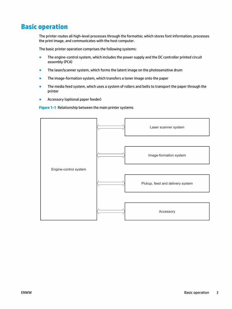
Basic operationThe printer routes all high-level processes through the formatter, which stores font information, processes the print image, and communicates with the host computer.
The basic printer operation comprises the following systems:
● The engine-control system, which includes the power supply and the DC controller printed circuit assembly (PCA)
● The laser/scanner system, which forms the latent image on the photosensitive drum
● The image-formation system, which transfers a toner image onto the paper
● The media feed system, which uses a system of rollers and belts to transport the paper through the printer
● Accessory (optional paper feeder)
Figure 1-1 Relationship between the main printer systems
Engine-control system
Laser scanner system
Image-formation system
Pickup, feed and delivery system
Accessory
Engine-control system
Laser scanner system
Image-formation system
Pickup, feed and delivery system
Accessory
ENWW Basic operation 3
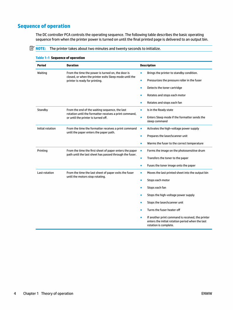
Sequence of operationThe DC controller PCA controls the operating sequence. The following table describes the basic operating sequence from when the printer power is turned on until the final printed page is delivered to an output bin.
NOTE: The printer takes about two minutes and twenty seconds to initialize.
Table 1-1 Sequence of operation
Period Duration Description
Waiting From the time the power is turned on, the door is closed, or when the printer exits Sleep mode until the printer is ready for printing.
● Brings the printer to standby condition.
● Pressurizes the pressure roller in the fuser
● Detects the toner cartridge
● Rotates and stops each motor
● Rotates and stops each fan
Standby From the end of the waiting sequence, the last rotation until the formatter receives a print command, or until the printer is turned off.
● Is in the Ready state
● Enters Sleep mode if the formatter sends the sleep command
Initial rotation From the time the formatter receives a print command until the paper enters the paper path.
● Activates the high-voltage power supply
● Prepares the laser/scanner unit
● Warms the fuser to the correct temperature
Printing From the time the first sheet of paper enters the paper path until the last sheet has passed through the fuser.
● Forms the image on the photosensitive drum
● Transfers the toner to the paper
● Fuses the toner image onto the paper
Last rotation From the time the last sheet of paper exits the fuser until the motors stop rotating.
● Moves the last printed sheet into the output bin
● Stops each motor
● Stops each fan
● Stops the high-voltage power supply
● Stops the laser/scanner unit
● Turns the fuser heater off
● If another print command is received, the printer enters the initial rotation period when the last rotation is complete.
4 Chapter 1 Theory of operation ENWW
Formatter-control system
The formatter performs the following functions:
● Controlling sleep mode
● Receiving and processing print data from the various printer interfaces
● Monitoring control panel functions and relaying printer status information (through the control panel and the network or bi-directional interface)
● Developing and coordinating data placement and timing with the DC controller PCA
● Storing font information
● Communicating with the host computer through the network or the bidirectional interface
The formatter receives a print job from the network or bidirectional interface and separates it into image information and instructions that control the printing process. The DC controller PCA synchronizes the image formation system with the paper input and output systems, and then signals the formatter to send the print image data.
The formatter also provides the electrical interface and mounting locations for the Slim DIMM and the optional hard-disk drive (HDD).
Sleep mode
NOTE: In the General Settings menu (a submenu of the Administration menu), this item is termed Sleep Timer Settings.
This feature conserves power after the printer has been idle for an adjustable period of time. When the printer is in Sleep mode, the printer retains all settings, downloaded fonts, and macros. The default setting is for Sleep mode to be enabled, and the printer enters Sleep mode after a 30-second idle time.
The printer firmware uses a combination of timers and Sleep settings to control when the printer enters a different state as well as what states the printer will enter. The available states are listed below, in descending order, from using the most power to using the least power:
● Active: The printer control panel is fully illuminated. The power button light is illuminated.
● Shallow suspend: The printer control panel is dim and the content is grayed out, but is still readable. The power button light is illuminated.
● Suspend: The printer control panel is off (blacked out). The power button light blinks once every three seconds.
● Deep suspend: The printer control panel is off (blacked out). The power button light blinks once every three seconds. The control panel and power button appearance is the same in this state as the suspend state. However, the printer is drawing less than 1 watt of power in the deep suspend state (as opposed to 6 watts of power in the suspend state).
● Off: This state is entered by pressing the power button or removing power from the printer. The power button light is not illuminated.
ENWW Formatter-control system 5
The printer exits Sleep mode and enters the warm-up cycle when any of the following events occur:
● The printer receives a print job, valid data, or a PML or PJL command.
● A control-panel button is pressed or the touchscreen is touched.
● A cover or door is opened.
● The engine-test switch is pressed.
● A paper tray, other than Tray 1, is opened.
NOTE: If the printer is in the deep suspend state, opening a paper tray will not cause the printer to exit Sleep mode.
NOTE: Printer error messages override the Sleep message. The printer enters Sleep mode at the appropriate time, but the error message continues to appear.
Printer job language (PJL)PJL is an integral part of printer configuration, in addition to the standard printer command language (PCL) and PostScript (PS). With standard cabling, the printer can use PJL to perform a variety of functions, such as these:
● Two-way communication with the host computer through a network connection or a USB device port: The printer can inform the host about the control-panel settings, and the control-panel settings can be changed from the host.
● Dynamic I/O switching: The printer uses this switching to be configured with a host on each I/O. The printer can receive data from more than one I/O simultaneously, until the I/O buffer is full. This can occur even when the printer is offline.
● Context-sensitive switching: The printer can automatically recognize the personality (PS or PCL) of each job and configure itself to serve that personality.
● Isolation of print environment settings from one print job to the next: For example, if a print job is sent to the printer in landscape mode, the subsequent print jobs print in landscape only if they are formatted for landscape printing.
Printer management language (PML)PML allows remote configuration of the printer and status read-back from the printer through the I/O ports.
Control panelThe M604n, M605n, M604dn, M605dn, and M606dn control panel is a 6.85 cm (2.7 in) four-line color display with numeric keypad and additional buttons for navigating control panel menus. The M605x and M606x control panel is a 20.3 cm (8 in) full-color SVGA with capacitive touchscreen and adjustable viewing angle.
The M605x and M606x control panel has a diagnostic mode to allow testing of the touchscreen, Home button, and speaker. The control panel does not require calibration.
All models include an easy-access USB port for walk-up printing and a hardware integration pocket for third-party USB devices, such as card readers.
6 Chapter 1 Theory of operation ENWW
Easy-access USB portThis printer features easy-access USB printing, for quickly printing files without sending them from a computer. The printer accepts standard USB flash drives in the USB port near the control panel. It supports the following types of files:
● .prn
● .pcl
● .ps
● .cht
The USB port is disabled by default. Follow the instructions in the printer user guide to enable the USB port and print USB documents.
WirelessThe M605x and M606x contains a wireless card to enable 802.11b/g/n wireless communication.
Near field communication (NFC)
The M605x and M606x printer supports near field communication (NFC) capabilities. NFC enables an easy one-to-one HP wireless direct print connection using a simple device-to-device touch. Mobile device users can quickly connect to the printer and print documents and images from a mobile device, such as a smartphone or tablet, by touching the device to the NFC icon on the bottom of the control panel.
CPU
The formatter incorporates an 800 MHz processor.
Input/output
The printer has three I/O interfaces:
● Hi-Speed USB 2.0
● 10/100/1000 Ethernet LAN connection with IPv4 and IPv6
● Easy-access USB printing (no computer required)
Memory
If the printer encounters a problem when managing available memory, a clearable warning message appears on the control panel.
The formatter incorporates different types of memory and storage to store the printer firmware as well as print-job data and user settings.
ENWW Formatter-control system 7

● 512 MB base memory, expandable to 1.0 GB or 1.5 GB by adding DIMM memory modules
● HP Secure High-Performance Hard Disk (HDD; optional)
Firmware
Memory on the formatter or an optional hard-disk drive (HDD) attached to the formatter store the firmware. A remote firmware upgrade process is used to overwrite and upgrade the firmware.
Nonvolatile random access memory (NVRAM)
The printer uses NVRAM to store printer and user configuration settings. The contents of NVRAM are retained when the printer is turned off or disconnected.
Random access memory (RAM)
The formatter has one DIMM slot. All models come with 512 MB base memory installed. Additional memory can be added up to a maximum of 1.5 GB.
The RAM on the formatter contains the page, I/O buffers, and the font storage area. It stores printing and font information received from the host system, and can also serve to temporarily store a full page of print-image data before the data is sent to the print engine.
NOTE: If the printer encounters a problem when managing available memory, a clearable warning message displays on the control panel display.
HP Memory Enhancement technology (MEt)
MEt effectively doubles the amount of standard memory through a variety of font- and data-compression methods.
NOTE: MEt is available only in when printing in printer command language (PCL) mode. It is not functional when printing in PostScript (PS) mode.
8 Chapter 1 Theory of operation ENWW
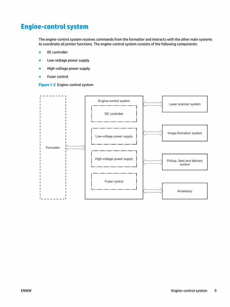
Engine-control system
The engine-control system receives commands from the formatter and interacts with the other main systems to coordinate all printer functions. The engine-control system consists of the following components:
● DC controller
● Low-voltage power supply
● High-voltage power supply
● Fuser control
Figure 1-2 Engine-control system
Formatter
Engine-control system
DC controller
Low-voltage power supply
Laser scanner system
Image-formation system
Pickup, feed and delivery system
Accessory
High-voltage power supply
Fuser control
Formatter
Engine-control system
DC controller
Low-voltage power supply
Laser scanner system
Image-formation system
Pickup, feed and deliverysystem
Accessory
High-voltage power supply
Fuser control
ENWW Engine-control system 9
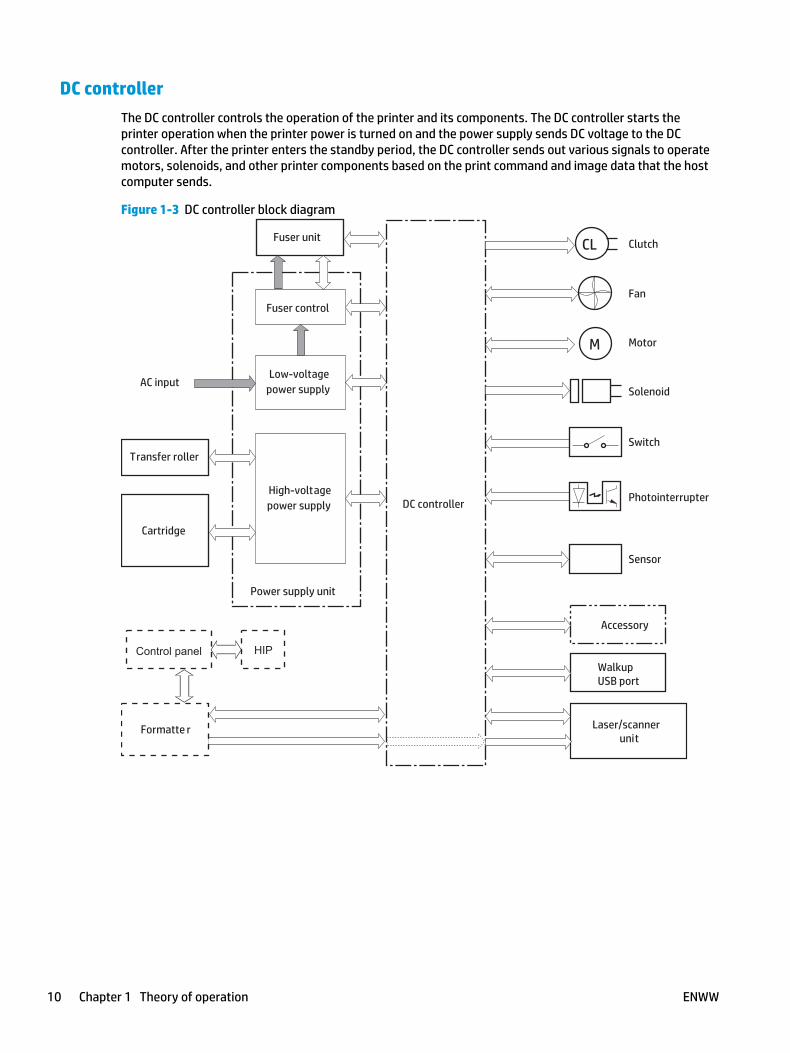
DC controllerThe DC controller controls the operation of the printer and its components. The DC controller starts the printer operation when the printer power is turned on and the power supply sends DC voltage to the DC controller. After the printer enters the standby period, the DC controller sends out various signals to operate motors, solenoids, and other printer components based on the print command and image data that the host computer sends.
Figure 1-3 DC controller block diagram
AC input
M
CLFuser unit
Motor
Transfer roller
High-voltagepower supply
Low-voltagepower supply
Laser/scannerunit
Solenoid
Formatte r
Cartridge
PhotointerrupterDC controller
Switch
Fan
Accessory
WalkupUSB port
Clutch
Fuser control
Sensor
Power supply unit
HIPControl panel
10 Chapter 1 Theory of operation ENWW

Motors
The printer has four direct current (DC) motors. The motors drive the components in the paper-feed and image-formation systems.
The DC controller monitors the fuser motor, the paper feed motor, and the drum motor to determine if a motor has failed. It notifies the formatter when it encounters the following conditions:
● Startup failure: the motor does not reach a specified speed within a specified time from when the motor starts.
● Rotational failure: the rotational speed of the motor is not in the specified range for a specified time after the motor reaches a specified speed.
Table 1-2 Motors
Abbreviation Name Purpose Failure detection
M101 Paper feed motor Drives the Tray 1 pickup roller, Tray 2 pickup roller, and feed roller.
Yes
M102 Drum motor Drives the photosensitive drum, primary charging roller, and transfer roller.
Yes
M299 Fuser motor Drives the pressure roller and feed roller—when rotated counterclockwise it releases the fusing pressure for easier jam removal.
Yes
M103 Lifter motor Drives the lifting plate of the tray. No1
1 This motor does not have direct failure detection. However, if the error message 60.00.02 Lifting Error appears on the control-panel display, it could indicate that this motor has failed.
Fans
The printer has four fans that prevent the temperature from rising in the printer and for cooling the printed pages.
The DC controller determines if there is a fan failure and notifies the formatter if the fan locks for a specified time from when the fan starts.
Table 1-3 Fans
Abbreviation Name Cooling area Type Speed
FN101 Cooling fan Power supply area left side Intake Full/half1
FN102 Cooling fan Toner cartridge area right side Intake Full2
FN103 Cooling fan Toner cartridge area left side Intake Full2
FN104 Cooling fan Laser/scanner right side Intake Full2
1 Cooling fan FN101 rotates at full speed for eight seconds when the printer is turned on, and then decreases to half-speed for approximately 10 minutes. After that time period, if there is no print job in the print queue, the fan will stop completely. The fan rotates at full speed during a print job.
2 This fan operates at full speed only during a print job. Otherwise, it does not rotate.
ENWW Engine-control system 11
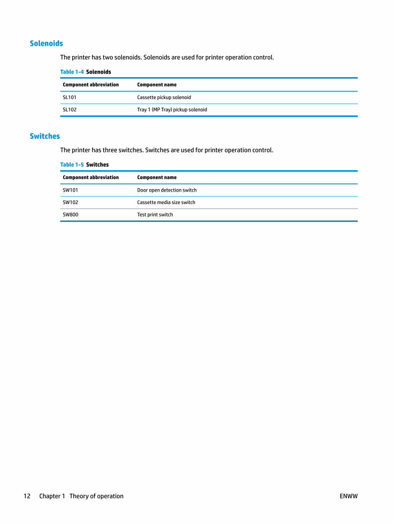
Solenoids
The printer has two solenoids. Solenoids are used for printer operation control.
Table 1-4 Solenoids
Component abbreviation Component name
SL101 Cassette pickup solenoid
SL102 Tray 1 (MP Tray) pickup solenoid
Switches
The printer has three switches. Switches are used for printer operation control.
Table 1-5 Switches
Component abbreviation Component name
SW101 Door open detection switch
SW102 Cassette media size switch
SW800 Test print switch
12 Chapter 1 Theory of operation ENWW

Sensors
The printer has twelve sensors. Sensors are used for remote detection of various functions during printer operation.
Table 1-6 Sensors
Component abbreviation Component name
PS101 Cassette media presence senor
PS102 Pre-feed sensor
PS103 Top-of-page sensor
PS104 Face-down tray media full sensor
PS105 Tray 1 (MP tray) media presence sensor
PS106 Media width sensor 1
PS107 Media stack surface sensor 1
PS108 Media width sensor 2
PS699 Fixing (fuser) pressure release sensor
PS700 Fixing (fuser) delivery sensor
PS907 Media stack surface sensor 2
TH3 Environmental sensor
ENWW Engine-control system 13
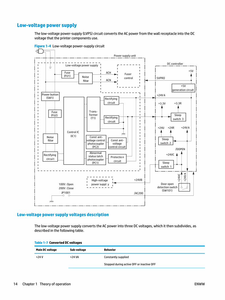
Low-voltage power supplyThe low-voltage power-supply (LVPS) circuit converts the AC power from the wall receptacle into the DC voltage that the printer components use.
Figure 1-4 Low-voltage power-supply circuit
Trans-former
(T1)
Rectifyingcircuit
Const ant-voltage
control circuit
Abnormalstatus latch
photocoupler(PC1)
Const ant-voltage controlphotocoupler
(PC2)
Door opendetection switch
(SW101)
Control IC(IC1)
Fuse(FU1)
Power button(SW1)
Fuse(FU2)
100V : Open200V : Close
Power supply unit
Sleepswitch 3
High-voltage power suppl y
DC controller
+5Vgeneration circuit
Protectio n circuit
Low-voltage power supply
Fusercontrol
Noisefilter
Noisefilter
Rectifyingcircuit
Rectifyingcircui t
Sleepswitch 2
Sleepswitch 1
+24V A
ACH
ACN5VPRO
/AC200JP1001
+24VB
/DOPEN
+5V
+24V
A
+24V
C
+3.3R
+24R+24U
+3.3V
+24V A
+24VC
Low-voltage power supply voltages description
The low-voltage power supply converts the AC power into three DC voltages, which it then subdivides, as described in the following table.
Table 1-7 Converted DC voltages
Main DC voltage Sub-voltage Behavior
+24 V +24 VA Constantly supplied
Stopped during active OFF or inactive OFF
14 Chapter 1 Theory of operation ENWW
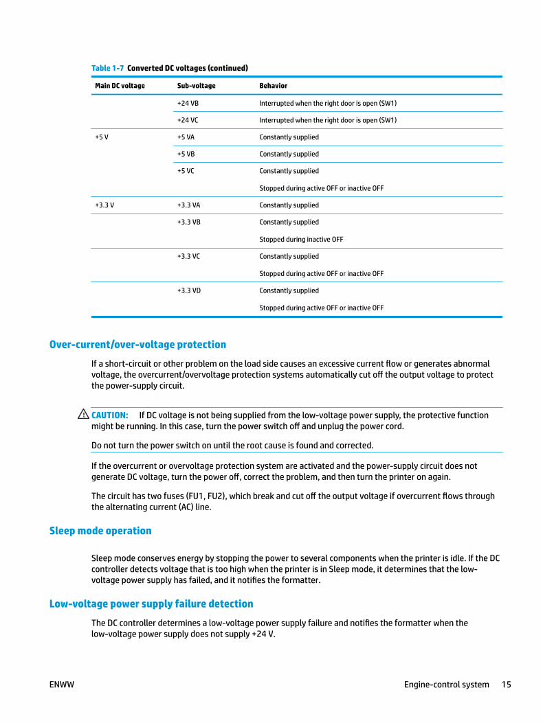
Table 1-7 Converted DC voltages (continued)
Main DC voltage Sub-voltage Behavior
+24 VB Interrupted when the right door is open (SW1)
+24 VC Interrupted when the right door is open (SW1)
+5 V +5 VA Constantly supplied
+5 VB Constantly supplied
+5 VC Constantly supplied
Stopped during active OFF or inactive OFF
+3.3 V +3.3 VA Constantly supplied
+3.3 VB Constantly supplied
Stopped during inactive OFF
+3.3 VC Constantly supplied
Stopped during active OFF or inactive OFF
+3.3 VD Constantly supplied
Stopped during active OFF or inactive OFF
Over-current/over-voltage protection
If a short-circuit or other problem on the load side causes an excessive current flow or generates abnormal voltage, the overcurrent/overvoltage protection systems automatically cut off the output voltage to protect the power-supply circuit.
CAUTION: If DC voltage is not being supplied from the low-voltage power supply, the protective function might be running. In this case, turn the power switch off and unplug the power cord.
Do not turn the power switch on until the root cause is found and corrected.
If the overcurrent or overvoltage protection system are activated and the power-supply circuit does not generate DC voltage, turn the power off, correct the problem, and then turn the printer on again.
The circuit has two fuses (FU1, FU2), which break and cut off the output voltage if overcurrent flows through the alternating current (AC) line.
Sleep mode operation
Sleep mode conserves energy by stopping the power to several components when the printer is idle. If the DC controller detects voltage that is too high when the printer is in Sleep mode, it determines that the low-voltage power supply has failed, and it notifies the formatter.
Low-voltage power supply failure detection
The DC controller determines a low-voltage power supply failure and notifies the formatter when the low‑voltage power supply does not supply +24 V.
ENWW Engine-control system 15
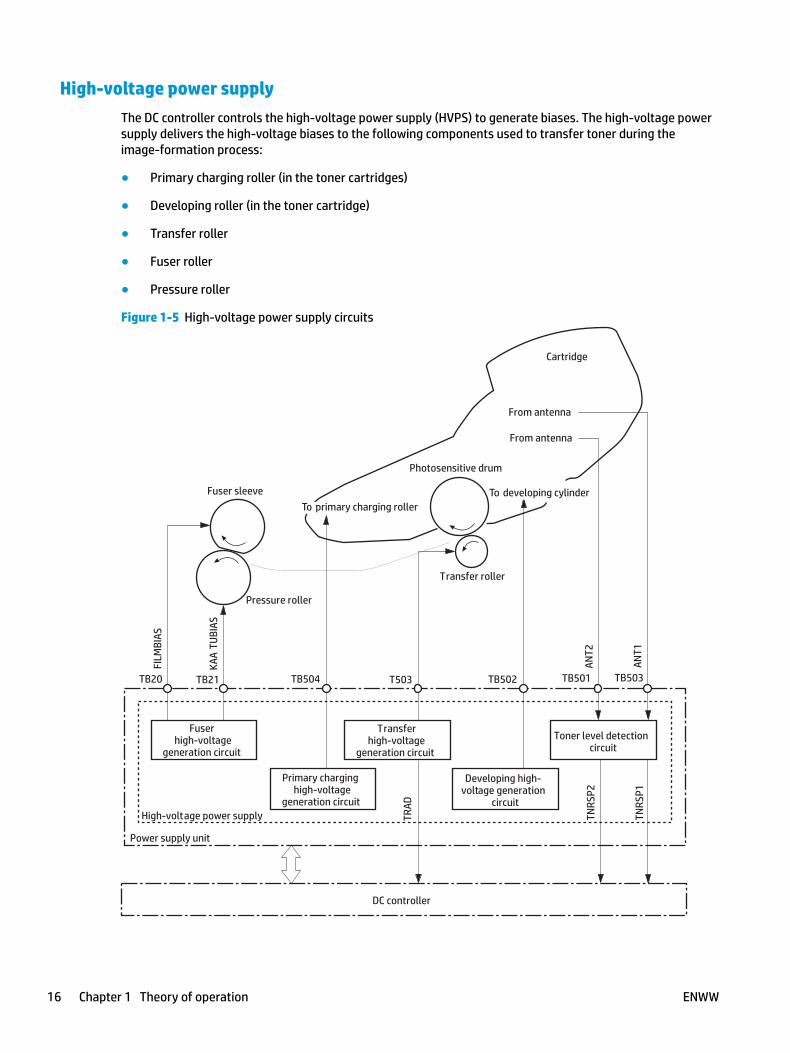
High-voltage power supplyThe DC controller controls the high-voltage power supply (HVPS) to generate biases. The high-voltage power supply delivers the high-voltage biases to the following components used to transfer toner during the image‑formation process:
● Primary charging roller (in the toner cartridges)
● Developing roller (in the toner cartridge)
● Transfer roller
● Fuser roller
● Pressure roller
Figure 1-5 High-voltage power supply circuits
Power supply unit
Fuser sleeve
From antenna
From antenna
Photosensitive drum
Transfer roller
DC controller
High-voltage power supply
Primary charginghigh-voltage
generation circuit
Developing high-voltage generation
circuit
Transferhigh-voltage
generation circuit
Fuserhigh-voltage
generation circuit
Pressure roller
To primary charging roller
Toner level detectioncircuit
To developing cylinder
Cartridge
TNRS
P2
TNRS
P1
TRAD
TB21TB20 TB504 T503 TB502 TB501 TB503
FILM
BIAS
KAA
TUBI
AS
ANT2
ANT1
16 Chapter 1 Theory of operation ENWW
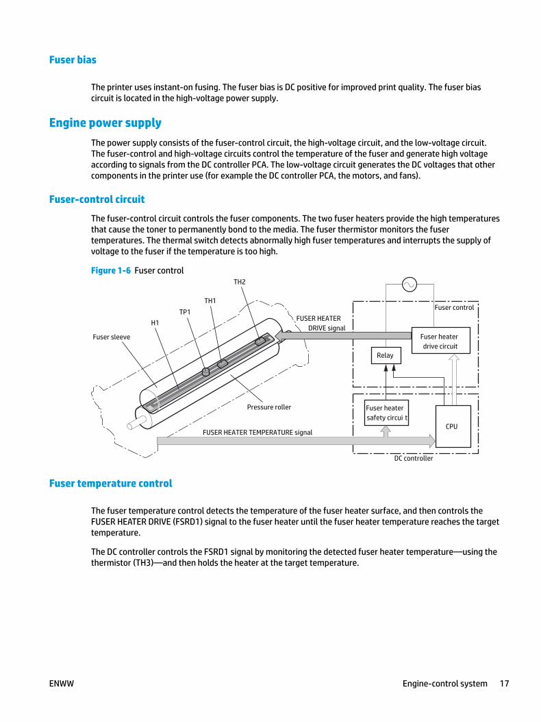
Fuser bias
The printer uses instant-on fusing. The fuser bias is DC positive for improved print quality. The fuser bias circuit is located in the high-voltage power supply.
Engine power supplyThe power supply consists of the fuser-control circuit, the high-voltage circuit, and the low-voltage circuit. The fuser-control and high-voltage circuits control the temperature of the fuser and generate high voltage according to signals from the DC controller PCA. The low-voltage circuit generates the DC voltages that other components in the printer use (for example the DC controller PCA, the motors, and fans).
Fuser-control circuit
The fuser-control circuit controls the fuser components. The two fuser heaters provide the high temperatures that cause the toner to permanently bond to the media. The fuser thermistor monitors the fuser temperatures. The thermal switch detects abnormally high fuser temperatures and interrupts the supply of voltage to the fuser if the temperature is too high.
Figure 1-6 Fuser control
DC controller
Fuser heaterdrive circuit
Fuser heatersafety circui t
Relay
CPU
Fuser control
FUSER HEATER TEMPERATURE signal
FUSER HEATERDRIVE signal
TH1TP1
H1
TH2
Pressure roller
Fuser sleeve
Fuser temperature control
The fuser temperature control detects the temperature of the fuser heater surface, and then controls the FUSER HEATER DRIVE (FSRD1) signal to the fuser heater until the fuser heater temperature reaches the target temperature.
The DC controller controls the FSRD1 signal by monitoring the detected fuser heater temperature—using the thermistor (TH3)—and then holds the heater at the target temperature.
ENWW Engine-control system 17
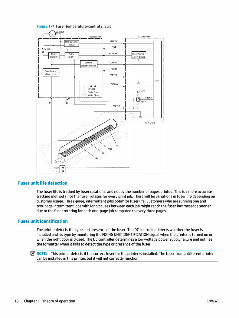
Figure 1-7 Fuser temperature-control circuit
JP1001100V: Open200V: Close
Relay(RL101)
Fuser heaterdrive circuit
Relay(RL102)
Zero crossingcircuit
Fuser control
AC input
DC controller
Currentdetection circuit
Fuser heatersafety circuit
H1
TH1
TH2
TP1
J12 8
Q704
+3.3V
/HITMP
FSRTH1
FSRD1
FSRTH2
/FSRARI
/AC200
CPU
/RLD
/ZEROX
CURRMS
FSRSAFE
TB10
TB11
2
1
+24VC
Fuser unit life detection
The fuser life is tracked by fuser rotations, and not by the number of pages printed. This is a more accurate tracking method since the fuser rotates for every print job. There will be variations in fuser life depending on customer usage. Three-page, intermittent jobs optimize fuser life. Customers who are running one and two‑page intermittent jobs with long pauses between each job might reach the fuser low message sooner due to the fuser rotating for each one-page job compared to every three pages.
Fuser unit identification
The printer detects the type and presence of the fuser. The DC controller detects whether the fuser is installed and its type by monitoring the FIXING UNIT IDENTIFICATION signal when the printer is turned on or when the right door is closed. The DC controller determines a low-voltage power supply failure and notifies the formatter when it fails to detect the type or presence of the fuser.
NOTE: This printer detects if the correct fuser for the printer is installed. The fuser from a different printer can be installed in this printer, but it will not correctly function.
18 Chapter 1 Theory of operation ENWW

Engine laser/scanner system
The laser/scanner system forms a latent image on the photosensitive drum according to the VIDEO signals sent from the formatter. The main components, such as the laser driver and scanner motor, are assembled as a laser/scanner unit and controlled by the DC controller. The DC controller allows the laser to emit light according to the VIDEO signals. The laser beam passes through the lenses and enters the scanner mirror that is rotating at constant speed. The laser beam is reflected by the scanner mirror, passes through the lenses, and scans on the photosensitive drum.
The DC controller receives instructions from the formatter regarding the image of the page to be printed. The DC controller signals the lasers to emit light, and the laser beams pass through lenses and onto the scanner mirror, which rotates at a constant speed. The mirror reflects the beam onto the photosensitive drum in the pattern required for the image, exposing the surface of the drum so it can receive toner.
The main components of the laser/scanner system are the laser assembly and the scanner motor assembly, which are controlled by signals sent from the DC controller.
ENWW Engine laser/scanner system 19
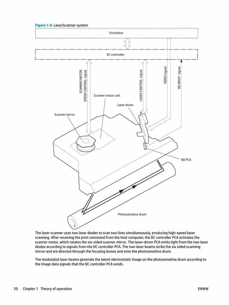
Figure 1-8 Laser/scanner system
BD PCA
Scanner mirror
Scanner motor unit
Photosensitive drum
Laser driver
Formatter
DC controller
LASE
R CO
NTRO
L s
igna
l
VIDE
O si
gnal
SCAN
NER
MOT
ORSP
EED
CONT
ROL
sign
al
BD IN
PUT
sig
nal
The laser scanner uses two laser diodes to scan two lines simultaneously, producing high-speed laser scanning. After receiving the print command from the host computer, the DC controller PCA activates the scanner motor, which rotates the six-sided scanner mirror. The laser-driver PCA emits light from the two laser diodes according to signals from the DC controller PCA. The two laser beams strike the six sided scanning mirror and are directed through the focusing lenses and onto the photosensitive drum.
The modulated laser beams generate the latent electrostatic image on the photosensitive drum according to the image data signals that the DC controller PCA sends.
20 Chapter 1 Theory of operation ENWW
1. As it receives a print command from the formatter, the dc controller outputs the SCANNER MOTOR SPEED CONTROL signal (/ACC) and rotates the scanner motor in order to rotate the six sided mirror.
2. As the scanner motor starts rotating, the dc controller uses a LASER CONTROL signal (CNT0, CNT1, CNT2) to receive the /BD INPUT signal (/BDI) and force the laser to emit light . The dc controller detects the rotational speed of the scanner motor based on the timing the /BD1 signal is input and controls the speed to keep it constant.
3. While the scanner motor rotates at a constant speed, the dc controller passes the VIDEO signals from the formatter on to the laser driver PCA. The laser driver PCA emits light from the two laser diodes according to these signals: VDO1, /VDO1, VDO2, /VDO2.
4. The two laser beams pass through the collimator lens and cylindrical lens and strike the six-sided mirror that is rotating at a constant speed.
5. The laser beams, that are reflected off of the six-sided mirror pass through the focus lens and reflective mirror and focus on the photosensitive drum. The laser beams scan the drum surface at a constant speed.
6. As the six-sided mirror rotates and the laser beam scans the drum surface at a constant speed, a latent image forms on the drum surface.
Laser failure detectionThe DC controller determines a laser/scanner unit failure and notifies the formatter, if the laser/scanner unit encounters the following conditions:
● Laser failure: The laser intensity is not detected for a specified value when the laser is turned on for a specified period during the scanner unit start-up period.
● BD failure: The BD interval is out of a specified value during a print operation.
● Scanner motor start-up failure: The scanner motor does not reach a specified rotation within a specified period from when the scanner motor starts rotation.
ENWW Engine laser/scanner system 21

Image formation process
The image formation system is the central hub of the printer. It also forms the toner image on the media.
● Toner cartridge
● Transfer roller
● Fuser
The DC controller controls the laser/scanner unit and high-voltage power supply to form an image on the media according to the VIDEO signals.
Figure 1-9 Image-formation system
High-voltage power supply circuit
Power supply unit
Laser beam
VIDEO signal
Laser/scanner unit
Fuser sleeve
Photosensitive drum
Transfer roller
DC controller
Pressure roller
To primary charging rollerTo developing cylinder
Cartridge
Formatter
TB21TB20 TB504 T503 TB502
The image-formation system consists of 8 steps divided into five functional blocks.
22 Chapter 1 Theory of operation ENWW
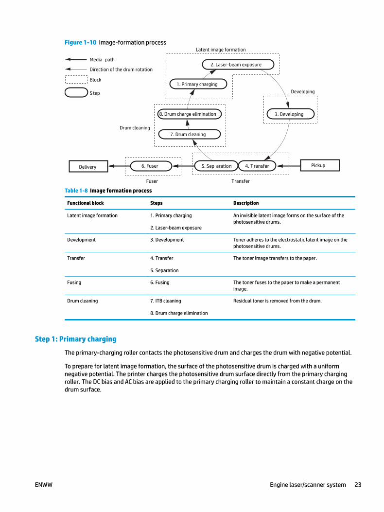
Figure 1-10 Image-formation process
8. Drum charge elimination
Drum cleaning
Transfer
Latent image formation
Developing
2. Laser-beam exposure
Fuser
6. FuserDelivery 5. Sep aration 4. T ransfer
7. Drum cleaning
3. Developing
1. Primary charging
Media path
Direction of the drum rotation
Pickup
Block
S tep
Table 1-8 Image formation process
Functional block Steps Description
Latent image formation 1. Primary charging
2. Laser-beam exposure
An invisible latent image forms on the surface of the photosensitive drums.
Development 3. Development Toner adheres to the electrostatic latent image on the photosensitive drums.
Transfer 4. Transfer
5. Separation
The toner image transfers to the paper.
Fusing 6. Fusing The toner fuses to the paper to make a permanent image.
Drum cleaning 7. ITB cleaning
8. Drum charge elimination
Residual toner is removed from the drum.
Step 1: Primary charging
The primary-charging roller contacts the photosensitive drum and charges the drum with negative potential.
To prepare for latent image formation, the surface of the photosensitive drum is charged with a uniform negative potential. The printer charges the photosensitive drum surface directly from the primary charging roller. The DC bias and AC bias are applied to the primary charging roller to maintain a constant charge on the drum surface.
ENWW Engine laser/scanner system 23

Figure 1-11 Primary charging
Photosensitive drum
Primary charging roller
Primary charging bias
Step 2: Laser-beam exposure
The laser beam strikes the surface of the photosensitive drum in the areas where the image will form. The negative charge neutralizes in those areas, which are then ready to accept toner.
Figure 1-12 Laser-beam exposure
Photosensitive drum
Laser beam
Step 3: Development
Toner acquires a negative charge as the developing cylinder contacts the developing blade. Because the negatively charged surface of the photosensitive drums have been neutralized where they have been struck by the laser beam, the toner adheres to those areas on the drums. The latent image becomes visible on the surface of each drum.
24 Chapter 1 Theory of operation ENWW
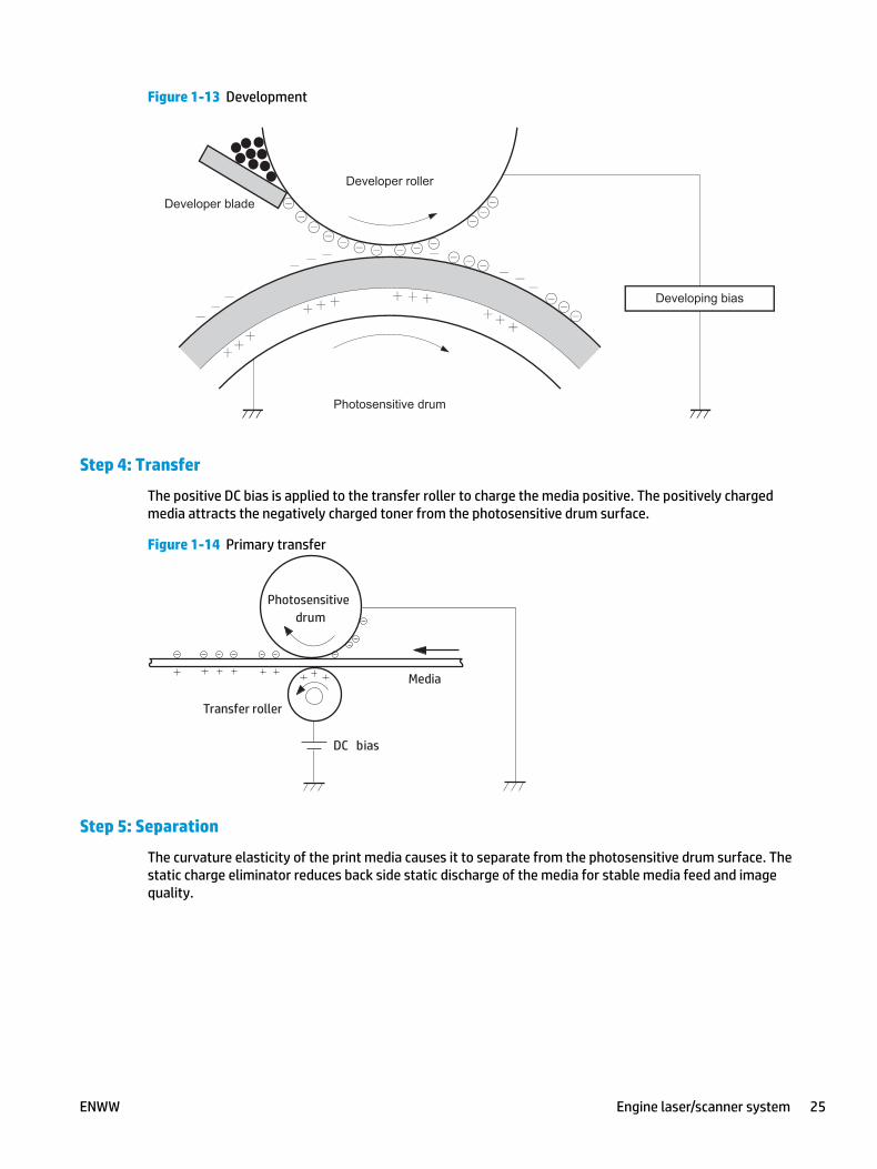
Figure 1-13 Development
Developer roller
Developing bias
Photosensitive drum
Developer blade
Step 4: Transfer
The positive DC bias is applied to the transfer roller to charge the media positive. The positively charged media attracts the negatively charged toner from the photosensitive drum surface.
Figure 1-14 Primary transfer
Media
Transfer roller
Photosensitivedrum
DC bias
Step 5: Separation
The curvature elasticity of the print media causes it to separate from the photosensitive drum surface. The static charge eliminator reduces back side static discharge of the media for stable media feed and image quality.
ENWW Engine laser/scanner system 25
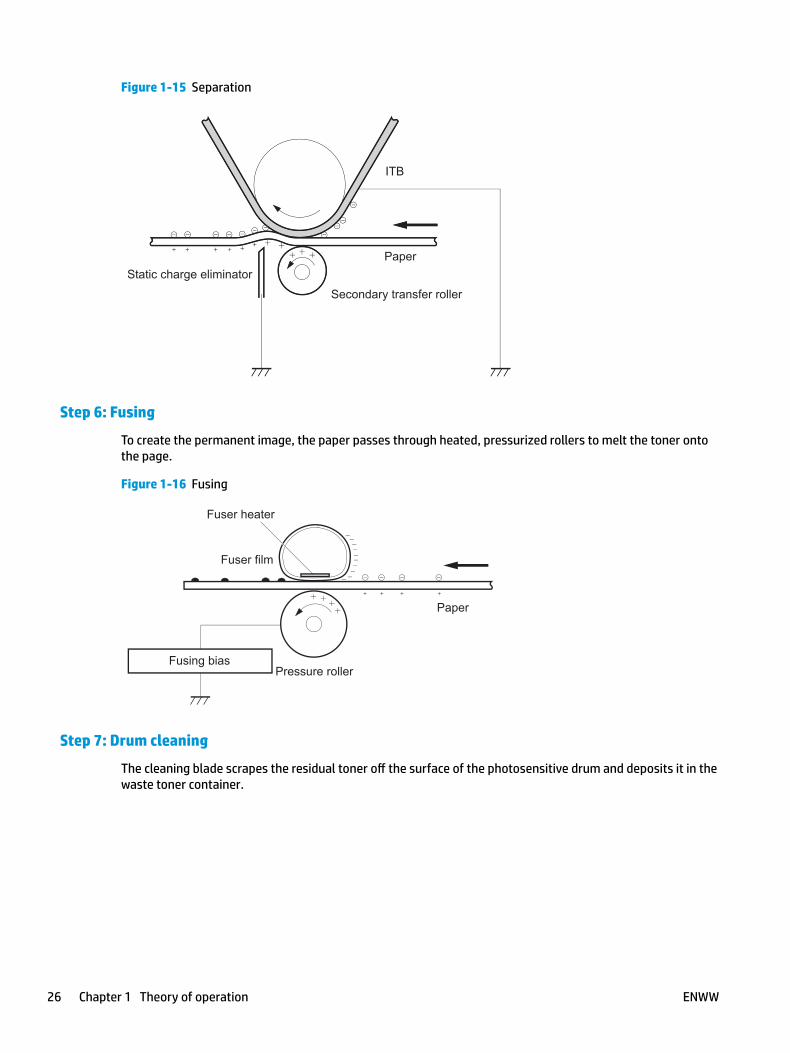
Figure 1-15 Separation
ITB
Paper
Secondary transfer roller
Static charge eliminator
ITB
Paper
Secondary transfer roller
Static charge eliminator
Step 6: Fusing
To create the permanent image, the paper passes through heated, pressurized rollers to melt the toner onto the page.
Figure 1-16 Fusing
Paper
Fuser film
Fuser heater
Pressure rollerFusing bias
Step 7: Drum cleaning
The cleaning blade scrapes the residual toner off the surface of the photosensitive drum and deposits it in the waste toner container.
26 Chapter 1 Theory of operation ENWW
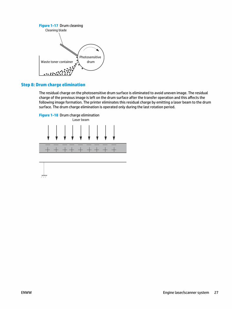
Figure 1-17 Drum cleaning
Waste toner containerPhotosensitive
drum
Cleaning blade
Step 8: Drum charge elimination
The residual charge on the photosensitive drum surface is eliminated to avoid uneven image. The residual charge of the previous image is left on the drum surface after the transfer operation and this affects the following image formation. The printer eliminates this residual charge by emitting a laser beam to the drum surface. The drum charge elimination is operated only during the last rotation period.
Figure 1-18 Drum charge eliminationLaser beam
ENWW Engine laser/scanner system 27

Pickup, feed, and delivery system
The DC controller controls the pickup, feed, and delivery system according to commands from the formatter. The pickup, feed, and delivery system uses a series of rollers to move the paper through the printer.
Photo sensors and switchesThe Tray 1 paper sensor (on the Tray 1 pickup assembly; PS105) detects media in Tray 1. The Tray 2 paper sensor (PS101) detects media in Tray 2. The paper-size switch (SW102) detects the media size that is loaded in Tray 2.
The pre-feed, top-of-page, and fuser-assembly delivery sensors (PS102, PS103, PS700) detect media arriving and passing along the paper path. If the media does not reach or pass these sensors within a specific amount of time, the microprocessor on the DC controller PCA halts the printer functions and a jam error message appears on the control-panel display.
Figure 1-19 Photo sensors
PS907PS107
PS101
PS102PS105
PS106PS108
PS103PS700PS699
SW102
PS104
Separation roller
Pickup roller
Pickup arm
Lifter
Lifting plate
Transfer roller
Photosensitive drum
Lifting plate
Pre-transfer roller
Registration shutter
Feed roller
Feed roller
Fixing sleeve
Pressure roller
Face-down delivery roller
Motors, clutches, and solenoidsWhen it receives a print command from the host computer, the DC controller PCA turns on the feed motor (M101) power. The motor drives the Tray 2 pickup, feed, and separation rollers. The drum motor power also turns on. The laser/ scanner motor power turns on.
28 Chapter 1 Theory of operation ENWW

The DC controller PCA then activates the feed clutch (CL101) to rotate the feed roller. The Tray 2 pickup solenoid is activated (SL101) and the pickup arm descends. The pickup roller touches the media and a sheet is fed into the printer. The separation roller prevents multiple sheets of media from being fed at one time.
As the pre-feed sensor (PS102) detects the media, the dc controller PCA turns off the clutch, which stops the media. When the DC controller PCA detects that the laser/scanner is ready it activates the feed clutch again. The feed roller moves the media farther into the printer. The registration shutter corrects page skew and the media is transported to the designated output area.
Tray 1 (multipurpose)/Tray 2 (base printer)Moving paper from Tray 1 and Tray 2 involves the interaction of multiple components within the printer. The following sections describe these processes.
Tray 1 paper pickup and feed
The printer picks up one sheet of paper from Tray 1.
NOTE: Tray 1 and Tray 2 are optimal for paper pickup when using special paper or media other than 20lb plain paper. For Tray 1 and Tray 2 the printer increases the number of attempts to pickup a page, which increases the reliability of successfully picking the page from the tray and decreases the possibility of a mis‑pick jam.
HP recommends using Tray 1 or Tray 2 if the printer is experiencing excessive or reoccurring jams from trays other than Tray 1 and Tray 2, or for print jobs that require media other than 20 lb plain paper.
The Tray 1 paper sensor (PS105) detects the presence of media in Tray 1. When the DC controller PCA receives the print command, the printer starts the initial rotation phase, which consists of feed motor warm-up, scanner motor warm-up, high-voltage control sequence, and fuser warm-up. When the initial rotation phase ends, the Tray 1 pickup solenoid (SL102) is activated.
The cam rotates, the paper-tray lifter rises, and the media comes in contact with the Tray 1 pickup roller. At the same time, the Tray 1 pickup roller rotates twice and picks up a sheet of media from Tray 1. The separation pad prevents additional sheets from feeding with the first sheet.
The sheet then reaches the registration assembly, where its skew is corrected. The sheet then passes through the transfer, separation, and fusing stages; through the delivery unit; and is to the output bin.
NOTE: If media is removed from Tray 1 after the initial rotation phase, but before the pickup roller pulls the media from the tray, the Tray 1 pickup roller might continue to rotate up to six times, after which a jam detected.
Tray 2 paper presence detection
The media size detection switch (SW102) detects the presence and size of paper loaded in the tray.
The media size detection switch—comprised of three switches: upper, center, and lower—is active when the tray paper size plate is correctly positioned to the loaded paper size and the tray is installed in the printer. The DC controller determines the paper size by monitoring the switch conditions.
The DC controller determines a size mismatch and sends a signal to the formatter if the switches detect a paper size that is different from the size specified by the formatter.
Table 1-9 Media presence and size detection (Tray 2 and 1x500- sheet feeder)
Media size Media size switch settings
ENWW Pickup, feed, and delivery system 29
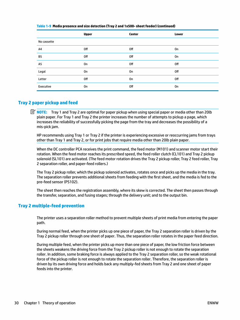
Table 1-9 Media presence and size detection (Tray 2 and 1x500- sheet feeder) (continued)
Upper Center Lower
No cassette
A4 Off Off On
B5 Off Off On
A5 On Off Off
Legal On On Off
Letter Off On Off
Executive On Off On
Tray 2 paper pickup and feed
NOTE: Tray 1 and Tray 2 are optimal for paper pickup when using special paper or media other than 20lb plain paper. For Tray 1 and Tray 2 the printer increases the number of attempts to pickup a page, which increases the reliability of successfully picking the page from the tray and decreases the possibility of a mis‑pick jam.
HP recommends using Tray 1 or Tray 2 if the printer is experiencing excessive or reoccurring jams from trays other than Tray 1 and Tray 2, or for print jobs that require media other than 20lb plain paper.
When the DC controller PCA receives the print command, the feed motor (M101) and scanner motor start their rotation. When the feed motor reaches its prescribed speed, the feed roller clutch (CL101) and Tray 2 pickup solenoid (SL101) are activated. (The feed motor rotation drives the Tray 2 pickup roller, Tray 2 feed roller, Tray 2 separation roller, and paper-feed rollers.)
The Tray 2 pickup roller, which the pickup solenoid activates, rotates once and picks up the media in the tray. The separation roller prevents additional sheets from feeding with the first sheet, and the media is fed to the pre-feed sensor (PS102).
The sheet then reaches the registration assembly, where its skew is corrected. The sheet then passes through the transfer, separation, and fusing stages; through the delivery unit; and to the output bin.
Tray 2 multiple-feed prevention
The printer uses a separation roller method to prevent multiple sheets of print media from entering the paper path.
During normal feed, when the printer picks up one piece of paper, the Tray 2 separation roller is driven by the Tray 2 pickup roller through one sheet of paper. Thus, the separation roller rotates in the paper feed direction.
During multiple feed, when the printer picks up more than one piece of paper, the low friction force between the sheets weakens the driving force from the Tray 2 pickup roller is not enough to rotate the separation roller. In addition, some braking force is always applied to the Tray 2 separation roller, so the weak rotational force of the pickup roller is not enough to rotate the separation roller. Therefore, the separation roller is driven by its own driving force and holds back any multiply-fed sheets from Tray 2 and one sheet of paper feeds into the printer.
30 Chapter 1 Theory of operation ENWW
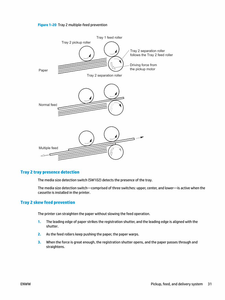
Figure 1-20 Tray 2 multiple-feed prevention
Tray 2 separation roller follows the Tray 2 feed roller
Driving force from the pickup motor
Normal feed
Multiple feed
Paper
Tray 2 pickup roller
Tray 2 separation roller
Tray 1 feed roller
Tray 2 separation roller follows the Tray 2 feed roller
Driving force from the pickup motor
Normal feed
Multiple feed
Paper
Tray 2 pickup roller
Tray 2 separation roller
Tray 1 feed roller
Tray 2 tray presence detection
The media size detection switch (SW102) detects the presence of the tray.
The media size detection switch—comprised of three switches: upper, center, and lower—is active when the cassette is installed in the printer.
Tray 2 skew feed prevention
The printer can straighten the paper without slowing the feed operation.
1. The leading edge of paper strikes the registration shutter, and the leading edge is aligned with the shutter.
2. As the feed rollers keep pushing the paper, the paper warps.
3. When the force is great enough, the registration shutter opens, and the paper passes through and straightens.
ENWW Pickup, feed, and delivery system 31
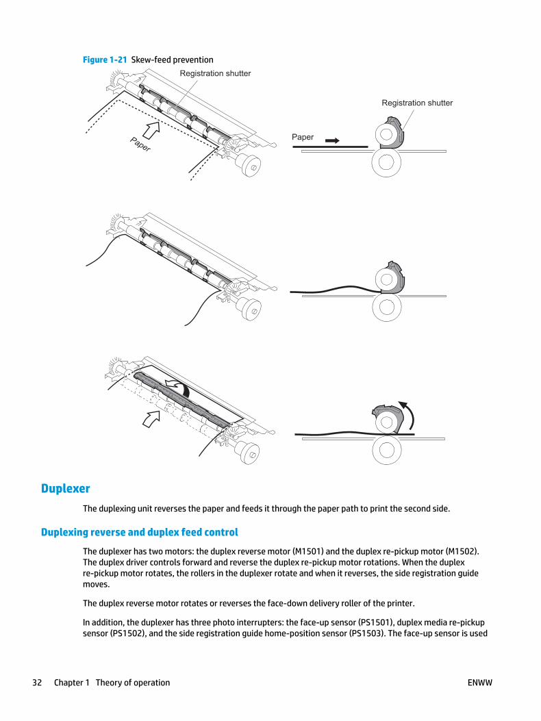
Figure 1-21 Skew-feed preventionRegistration shutter
Paper
Registration shutter
Paper
DuplexerThe duplexing unit reverses the paper and feeds it through the paper path to print the second side.
Duplexing reverse and duplex feed control
The duplexer has two motors: the duplex reverse motor (M1501) and the duplex re-pickup motor (M1502). The duplex driver controls forward and reverse the duplex re-pickup motor rotations. When the duplex re‑pickup motor rotates, the rollers in the duplexer rotate and when it reverses, the side registration guide moves.
The duplex reverse motor rotates or reverses the face-down delivery roller of the printer.
In addition, the duplexer has three photo interrupters: the face-up sensor (PS1501), duplex media re‑pickup sensor (PS1502), and the side registration guide home-position sensor (PS1503). The face-up sensor is used
32 Chapter 1 Theory of operation ENWW
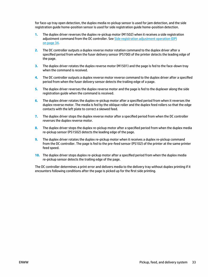
for face-up tray open detection, the duplex media re-pickup sensor is used for jam detection, and the side registration guide home-position sensor is used for side registration guide home-position detection.
1. The duplex driver reverses the duplex re-pickup motor (M1502) when it receives a side registration adjustment command from the DC controller. See Side registration adjustment operation (DP) on page 34.
2. The DC controller outputs a duplex reverse motor rotation command to the duplex driver after a specified period from when the fuser delivery sensor (PS700) of the printer detects the leading edge of the page.
3. The duplex driver rotates the duplex reverse motor (M1501) and the page is fed to the face-down tray when the command is received.
4. The DC controller outputs a duplex reverse motor reverse command to the duplex driver after a specified period from when the fuser delivery sensor detects the trailing edge of a page.
5. The duplex driver reverses the duplex reverse motor and the page is fed to the duplexer along the side registration guide when the command is received.
6. The duplex driver rotates the duplex re-pickup motor after a specified period from when it reverses the duplex reverse motor. The media is fed by the oblique roller and the duplex feed rollers so that the edge contacts with the left plate to correct a skewed feed.
7. The duplex driver stops the duplex reverse motor after a specified period from when the DC controller reverses the duplex reverse motor.
8. The duplex driver stops the duplex re-pickup motor after a specified period from when the duplex media re-pickup sensor (PS1502) detects the leading edge of the page.
9. The duplex driver rotates the duplex re-pickup motor when it receives a duplex re-pickup command from the DC controller. The page is fed to the pre-feed sensor (PS102) of the printer at the same printer feed speed.
10. The duplex driver stops duplex re‑pickup motor after a specified period from when the duplex media re‑pickup sensor detects the trailing edge of the page.
The DC controller determines a print error and delivers media to the delivery tray without duplex printing if it encounters following conditions after the page is picked up for the first side printing.
ENWW Pickup, feed, and delivery system 33
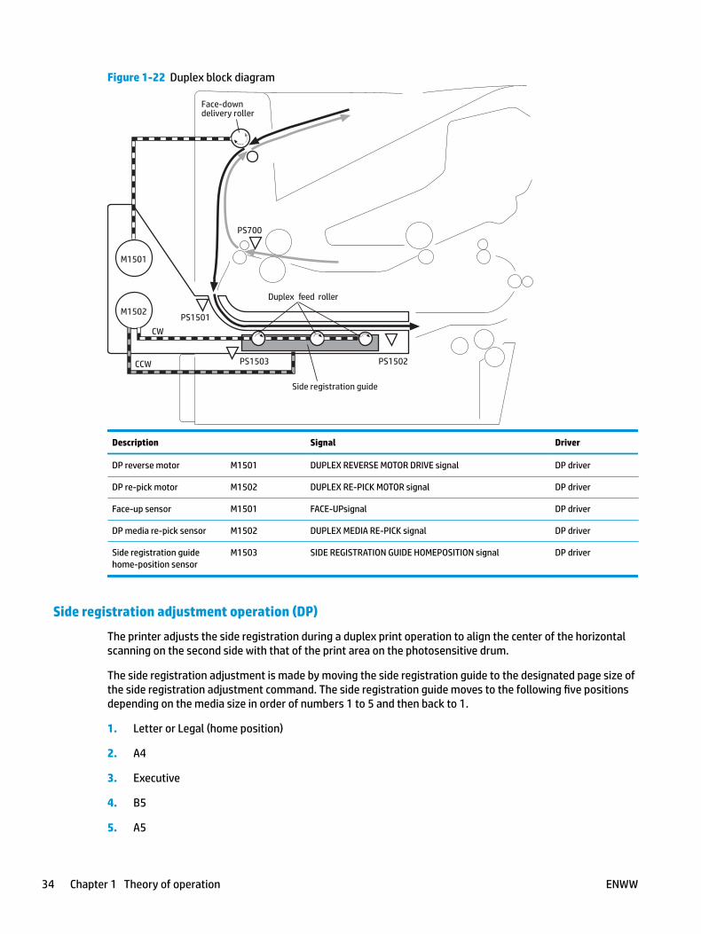
Figure 1-22 Duplex block diagram
M1502
M1501
PS1501
PS1502PS1503
PS700
Duplex feed roller
Face-downdelivery roller
CW
CCW
Side registration guide
Description Signal Driver
DP reverse motor M1501 DUPLEX REVERSE MOTOR DRIVE signal DP driver
DP re-pick motor M1502 DUPLEX RE-PICK MOTOR signal DP driver
Face-up sensor M1501 FACE-UPsignal DP driver
DP media re-pick sensor M1502 DUPLEX MEDIA RE-PICK signal DP driver
Side registration guide home-position sensor
M1503 SIDE REGISTRATION GUIDE HOMEPOSITION signal DP driver
Side registration adjustment operation (DP)
The printer adjusts the side registration during a duplex print operation to align the center of the horizontal scanning on the second side with that of the print area on the photosensitive drum.
The side registration adjustment is made by moving the side registration guide to the designated page size of the side registration adjustment command. The side registration guide moves to the following five positions depending on the media size in order of numbers 1 to 5 and then back to 1.
1. Letter or Legal (home position)
2. A4
3. Executive
4. B5
5. A5
34 Chapter 1 Theory of operation ENWW
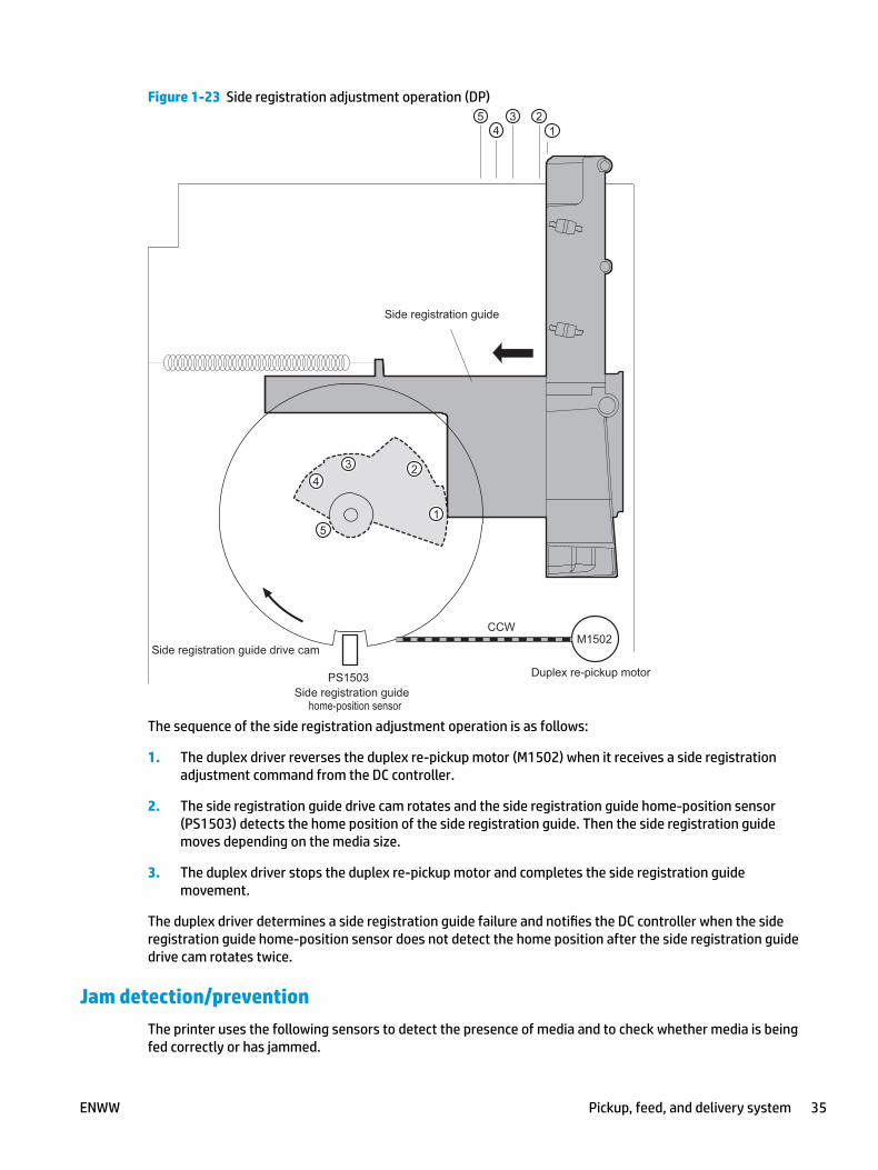
Figure 1-23 Side registration adjustment operation (DP)
home-position sensor
The sequence of the side registration adjustment operation is as follows:
1. The duplex driver reverses the duplex re-pickup motor (M1502) when it receives a side registration adjustment command from the DC controller.
2. The side registration guide drive cam rotates and the side registration guide home-position sensor (PS1503) detects the home position of the side registration guide. Then the side registration guide moves depending on the media size.
3. The duplex driver stops the duplex re-pickup motor and completes the side registration guide movement.
The duplex driver determines a side registration guide failure and notifies the DC controller when the side registration guide home-position sensor does not detect the home position after the side registration guide drive cam rotates twice.
Jam detection/preventionThe printer uses the following sensors to detect the presence of media and to check whether media is being fed correctly or has jammed.
ENWW Pickup, feed, and delivery system 35
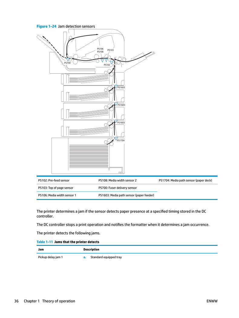
Figure 1-24 Jam detection sensors
PS1704
PS1603
PS1603
PS1603
PS102
PS103PS106PS108
PS700
PS102: Pre-feed sensor PS108: Media width sensor 2 PS1704: Media path sensor (paper deck)
PS103: Top of page sensor PS700: Fuser delivery sensor
PS106: Media width sensor 1 PS1603: Media path sensor (paper feeder)
The printer determines a jam if the sensor detects paper presence at a specified timing stored in the DC controller.
The DC controller stops a print operation and notifies the formatter when it determines a jam occurrence.
The printer detects the following jams.
Table 1-11 Jams that the printer detects
Jam Description
Pickup delay jam 1 a. Standard equipped tray
36 Chapter 1 Theory of operation ENWW

Table 1-11 Jams that the printer detects (continued)
Jam Description
The top of page sensor (PS103) does not detect the leading edge of media within a specified period from when the pre-feed sensor (PS102) detects the leading edge.
b. Pickup option
The top of page sensor (PS103) does not detect the leading edge of media within a specified period from when the feed clutch (CL101) is turned on.
c. Tray 1 (MP tray)
The top of page sensor (PS103) does not detect the leading edge of media within a specified period from when the MP tray pickup solenoid (SL102) is turned on.
Pickup delay jam 2 a. Standard equipped tray
The pre-feed sensor (PS102) does not detect the leading edge of media within a specified period from when a pickup operation starts.
b. Top pickup source of pickup option
The PF media path sensor (PS1603) for the top PF cassette or the PD media path sensor (PS1704) does not detect the leading edge of media within a specified period from when a pickup operation starts.
c. Lower pickup sources of pickup option
The PF media path sensor (PS1603) for the top PF cassette does not detect the leading edge of media within a specified period from when the PF media path sensor (PS1603) or the PD media path sensor (PS1704), either one of that equipped to the pickup source that picks up the media, detects the leading edge of media.
Pickup delay jam 3 The PF media path sensor (PS1603) or PD media path sensor (PS1704), either one of that equipped to the pickup source that picks up the media, does not detect the leading edge of media within a specified period from when a pickup operation from the lower pickup sources of the pickup option.
Pickup stationary jam a. Top of page sensor detection
The top of page sensor (PS103) does not detect the trailing edge of media within a specified period from when it detects the leading edge.
b. Media width sensors detection
Both of the media width sensors (PS106, PS108) do not detect the trailing edge of media within a specified period from when the top of page sensor (PS103) detects the trailing edge.
Delivery delay jam The fuser delivery sensor (PS700) does not detect the leading edge of media within a specified period from when the top of page sensor (PS103) detects the leading edge.
Delivery stationary jam The fuser delivery sensor (PS700) does not detect the trailing edge of media within a specified period from when the top of page sensor (PS103) detects the trailing edge.
Residual media jam 1 a. Either one of the following sensors detects media presence when the wait sequence starts:
ENWW Pickup, feed, and delivery system 37
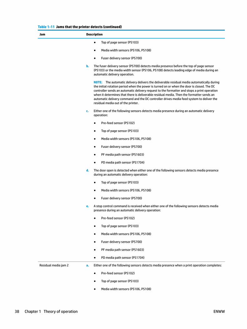
Table 1-11 Jams that the printer detects (continued)
Jam Description
● Top of page sensor (PS103)
● Media width sensors (PS106, PS108)
● Fuser delivery sensor (PS700)
b. The fuser delivery sensor (PS700) detects media presence before the top of page sensor (PS103) or the media width sensor (PS106, PS108) detects leading edge of media during an automatic delivery operation.
NOTE: The automatic delivery delivers the deliverable residual media automatically during the initial rotation period when the power is turned on or when the door is closed. The DC controller sends an automatic delivery request to the formatter and stops a print operation when it determines that there is deliverable residual media. Then the formatter sends an automatic delivery command and the DC controller drives media feed system to deliver the residual media out of the printer.
c. Either one of the following sensors detects media presence during an automatic delivery operation:
● Pre-feed sensor (PS102)
● Top of page sensor (PS103)
● Media width sensors (PS106, PS108)
● Fuser delivery sensor (PS700)
● PF media path sensor (PS1603)
● PD media path sensor (PS1704)
d. The door open is detected when either one of the following sensors detects media presence during an automatic delivery operation:
● Top of page sensor (PS103)
● Media width sensors (PS106, PS108)
● Fuser delivery sensor (PS700)
e. A stop control command is received when either one of the following sensors detects media presence during an automatic delivery operation:
● Pre-feed sensor (PS102)
● Top of page sensor (PS103)
● Media width sensors (PS106, PS108)
● Fuser delivery sensor (PS700)
● PF media path sensor (PS1603)
● PD media path sensor (PS1704)
Residual media jam 2 a. Either one of the following sensors detects media presence when a print operation completes:
● Pre-feed sensor (PS102)
● Top of page sensor (PS103)
● Media width sensors (PS106, PS108)
38 Chapter 1 Theory of operation ENWW

Table 1-11 Jams that the printer detects (continued)
Jam Description
● Fuser delivery sensor (PS700)
● PF media path sensor (PS1603)
● PD media path sensor (PS1704)
b. A stop control command is received from the formatter after a pickup operation has started.
Door open jam The door open is detected after a pickup operation has started.
Wrapping jam The fuser delivery sensor (PS700) detects media absence before it detects the trailing edge of media after a specified period from when it detects the leading edge.
Fuser wrapping jam detection
The printer includes controls for detecting when a jam occurs causing the paper to wrap around the fuser roller.
Pressure roller pressurization and depressurization control
The printer releases the pressure roller except during a print operation to improve usability for jammed paper removal.
The DC controller reverses the fuser motor (M299) to rotate the fuser pressure release cam. The pressure roller is pressurized or depressurized due to the shape of the cam.
The DC controller reverses the fuser motor to control the pressure roller pressurize or depressurize state according to the signal sent from the fuser pressure release sensor (PS699).
ENWW Pickup, feed, and delivery system 39

Figure 1-25 Pressure roller pressure release control
PS699
M299
FIXI
NG
MOT
ORDR
IVE
sign
al
DC controller
Fuser sleeve
Pressure roller
Fuser pressurerelease cam
Fuser pressure release sensor
Fuser motor
FIXI
NG P
RESS
URE
RELE
ASE
sign
al
<Pressurized> <Released>
The pressure roller depressurizes under the following conditions:
● When a paper jam is detected
● Factory shipment
The DC controller determines a fuser pressure release mechanism failure and notifies the formatter if the fuser roller release control is not completed within a specified period when it reverses the fuser motor.
40 Chapter 1 Theory of operation ENWW

Input accessoriesNOTE: The printer accepts up to four 1 x 500-sheet feeders, or three 1 x 500-sheet feeders and one 1,500-sheet high capaciy input tray.
● Trays 3-6
● High-capacity input (HCI) feeder
● Envelope feeder
● Duplexer
ENWW Input accessories 41
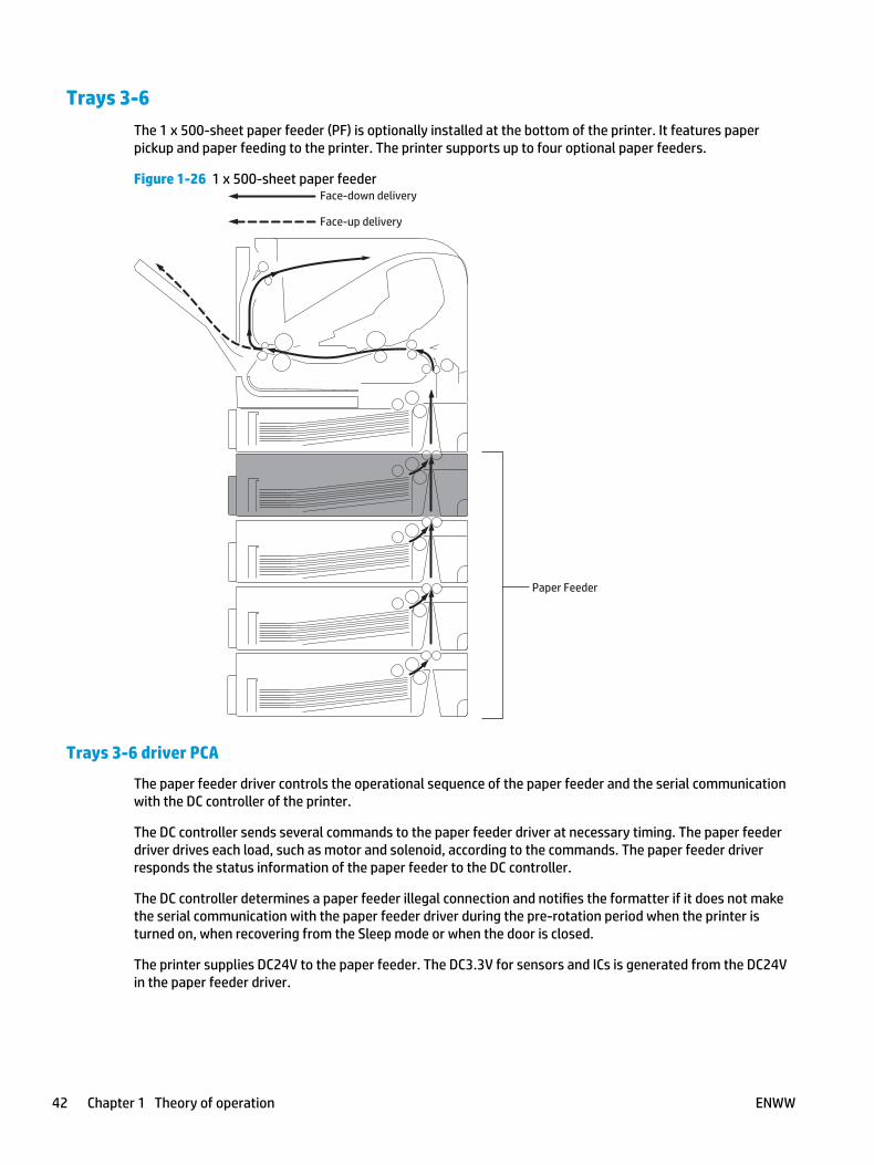
Trays 3-6 The 1 x 500-sheet paper feeder (PF) is optionally installed at the bottom of the printer. It features paper pickup and paper feeding to the printer. The printer supports up to four optional paper feeders.
Figure 1-26 1 x 500-sheet paper feeder
Paper Feeder
Face-down delivery
Face-up delivery
Trays 3-6 driver PCA
The paper feeder driver controls the operational sequence of the paper feeder and the serial communication with the DC controller of the printer.
The DC controller sends several commands to the paper feeder driver at necessary timing. The paper feeder driver drives each load, such as motor and solenoid, according to the commands. The paper feeder driver responds the status information of the paper feeder to the DC controller.
The DC controller determines a paper feeder illegal connection and notifies the formatter if it does not make the serial communication with the paper feeder driver during the pre-rotation period when the printer is turned on, when recovering from the Sleep mode or when the door is closed.
The printer supplies DC24V to the paper feeder. The DC3.3V for sensors and ICs is generated from the DC24V in the paper feeder driver.
42 Chapter 1 Theory of operation ENWW
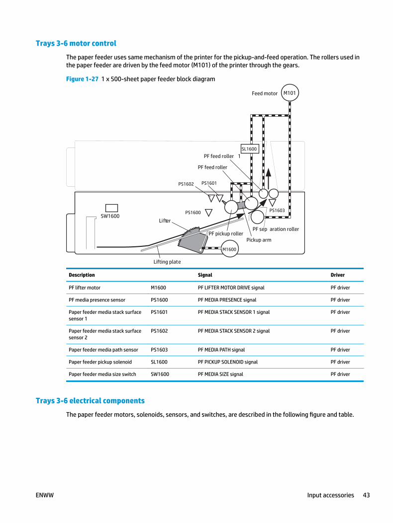
Trays 3-6 motor control
The paper feeder uses same mechanism of the printer for the pickup-and-feed operation. The rollers used in the paper feeder are driven by the feed motor (M101) of the printer through the gears.
Figure 1-27 1 x 500-sheet paper feeder block diagram
SW1600
PS1601PS1602
PS1600 PS1603
PF sep aration rollerPF pickup roller
PF feed roller
Pickup arm
Lifter
Lifting plate
Feed motor
M1600
SL1600
M101
PF feed roller 1
Description Signal Driver
PF lifter motor M1600 PF LIFTER MOTOR DRIVE signal PF driver
PF media presence sensor PS1600 PF MEDIA PRESENCE signal PF driver
Paper feeder media stack surface sensor 1
PS1601 PF MEDIA STACK SENSOR 1 signal PF driver
Paper feeder media stack surface sensor 2
PS1602 PF MEDIA STACK SENSOR 2 signal PF driver
Paper feeder media path sensor PS1603 PF MEDIA PATH signal PF driver
Paper feeder pickup solenoid SL1600 PF PICKUP SOLENOID signal PF driver
Paper feeder media size switch SW1600 PF MEDIA SIZE signal PF driver
Trays 3-6 electrical components
The paper feeder motors, solenoids, sensors, and switches, are described in the following figure and table.
ENWW Input accessories 43
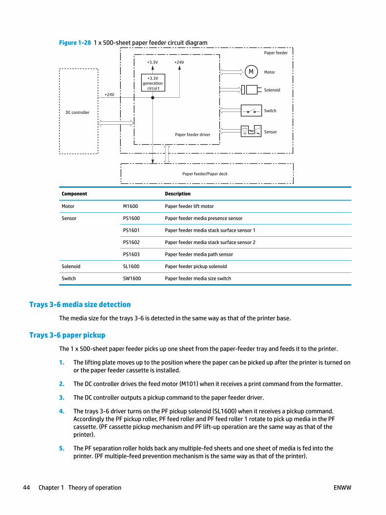
Figure 1-28 1 x 500-sheet paper feeder circuit diagram
M Motor
Solenoid
SensorPaper feeder driver
SwitchDC controller
Paper feeder
Paper feeder/Paper deck
+24V
+3.3Vgeneration
circui t
+3.3V +24V
Component Description
Motor M1600 Paper feeder lift motor
Sensor PS1600 Paper feeder media presence sensor
PS1601 Paper feeder media stack surface sensor 1
PS1602 Paper feeder media stack surface sensor 2
PS1603 Paper feeder media path sensor
Solenoid SL1600 Paper feeder pickup solenoid
Switch SW1600 Paper feeder media size switch
Trays 3-6 media size detection
The media size for the trays 3-6 is detected in the same way as that of the printer base.
Trays 3-6 paper pickup
The 1 x 500-sheet paper feeder picks up one sheet from the paper-feeder tray and feeds it to the printer.
1. The lifting plate moves up to the position where the paper can be picked up after the printer is turned on or the paper feeder cassette is installed.
2. The DC controller drives the feed motor (M101) when it receives a print command from the formatter.
3. The DC controller outputs a pickup command to the paper feeder driver.
4. The trays 3-6 driver turns on the PF pickup solenoid (SL1600) when it receives a pickup command. Accordingly the PF pickup roller, PF feed roller and PF feed roller 1 rotate to pick up media in the PF cassette. (PF cassette pickup mechanism and PF lift-up operation are the same way as that of the printer).
5. The PF separation roller holds back any multiple-fed sheets and one sheet of media is fed into the printer. (PF multiple-feed prevention mechanism is the same way as that of the printer).
44 Chapter 1 Theory of operation ENWW
Trays 3-6 multiple feed prevention
The trays 3-6 multiple-feed prevention for the paper feeder is operated in the same way as that of the printer base.
Trays 3-6 tray presence detection
The trays 3-6 tray presence detection for the paper feeder is the same way as that of the printer base.
Trays 3-6 tray lift operation
The lift-up operation keeps the stack surface of media in the paper feeder tray at a specified position to perform stable pickup operation.
The trays 3-6 driver drives the PF lifter motor (M1600) to move up the lifter plate in which media is stacked. The tray lift-up operation for the paper feeder is operated in the same way as that of the printer base.
The trays 3-6 driver monitors the PF media stack surface sensors (PS1601, PS1602) when the printer is turned on, when the PF tray is installed or during a print operation to perform the lift-up operation.
The sequence occurs as follows:
1. Initial lift-up operation
● The initial lift-up operation is performed if either one of the PF media stack surface sensors (PS1601,PS1602) does not detect the media surface when the power is turned on or when the PF cassette is installed. The trays 3-6 driver drives the PF lifter motor for a specified period after both of the PF stack surface sensors detect media and lifts the stack surface to the pickup position.
The trays 3-6 driver determines a PF lifter motor failure and notifies the DC controller if both of the PF media stack surface sensors do not detect media within a specified period from when a lift-up operation is started.
2. During print lift-up operation
● The during print lift-up operation is performed when the media surface is lowered for a specified level due to a pickup operation. The trays 3-6 driver drives the PF lifter motor for a specified period and lifts the stack surface to the pickup position when the PF media stack surface 1 (PS1601) detects media absence during a print operation.
If a tray media-stack-surface sensor does not detect a stack surface within a specified period after the PD lifter motor starts rotating, the trays 3-6 driver determines that the PD lifter motor has failed and through the DC controller notifies the formatter.
The trays 3-6 driver notifies the formatter if either of the paper-feeder media-stack surface sensors fails to detect the stack surface within a specified period from when a lift-up operation starts.
Trays 3-6 jam detection
The paper jam for trays 3-6 is detected by the DC controller of the printer base.
ENWW Input accessories 45
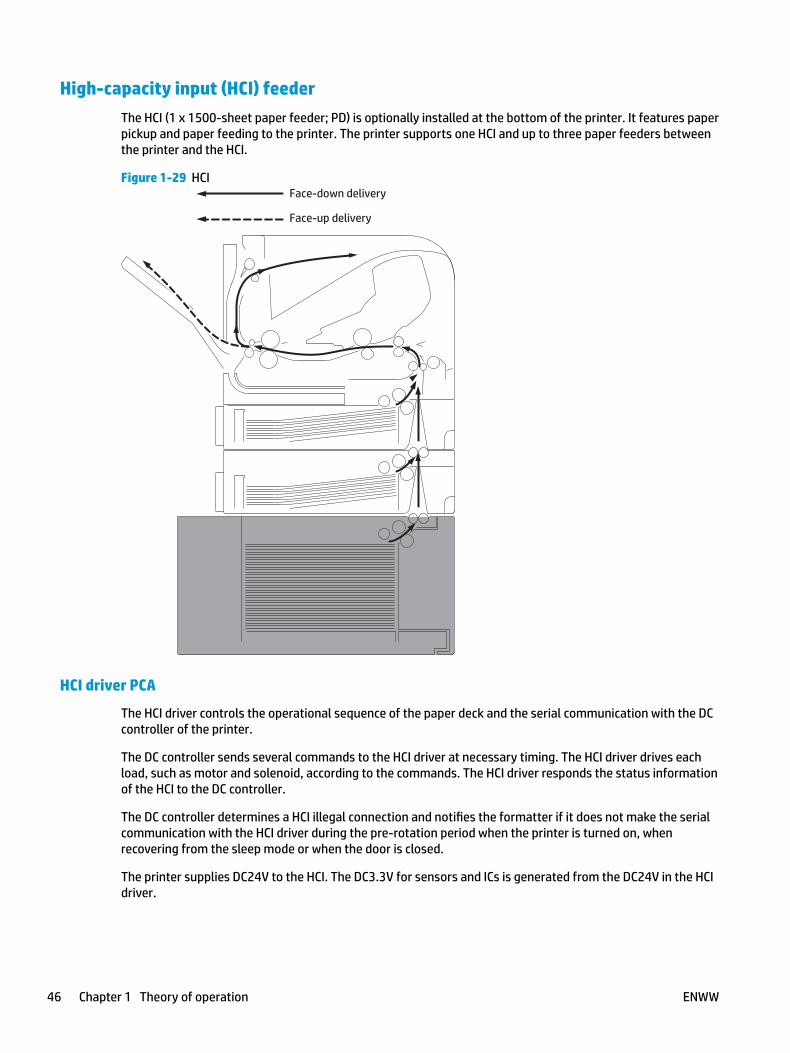
High-capacity input (HCI) feederThe HCI (1 x 1500-sheet paper feeder; PD) is optionally installed at the bottom of the printer. It features paper pickup and paper feeding to the printer. The printer supports one HCI and up to three paper feeders between the printer and the HCI.
Figure 1-29 HCIFace-down delivery
Face-up delivery
HCI driver PCA
The HCI driver controls the operational sequence of the paper deck and the serial communication with the DC controller of the printer.
The DC controller sends several commands to the HCI driver at necessary timing. The HCI driver drives each load, such as motor and solenoid, according to the commands. The HCI driver responds the status information of the HCI to the DC controller.
The DC controller determines a HCI illegal connection and notifies the formatter if it does not make the serial communication with the HCI driver during the pre-rotation period when the printer is turned on, when recovering from the sleep mode or when the door is closed.
The printer supplies DC24V to the HCI. The DC3.3V for sensors and ICs is generated from the DC24V in the HCI driver.
46 Chapter 1 Theory of operation ENWW
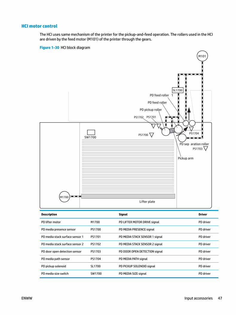
HCI motor control
The HCI uses same mechanism of the printer for the pickup-and-feed operation. The rollers used in the HCI are driven by the feed motor (M101) of the printer through the gears.
Figure 1-30 HCI block diagram
SW1700
PS1701PS1702
PS1700 PS1704
PS1703PD sep aration roller
PD pickup roller
PD feed roller
Pickup arm
Lifter plate
PD feed roller 1SL1700
M101
M1700
Description Signal Driver
PD lifter motor M1700 PD LIFTER MOTOR DRIVE signal PD driver
PD media presence sensor PS1700 PD MEDIA PRESENCE signal PD driver
PD media stack surface sensor 1 PS1701 PD MEDIA STACK SENSOR 1 signal PD driver
PD media stack surface sensor 2 PS1702 PD MEDIA STACK SENSOR 2 signal PD driver
PD door open detection sensor PS1703 PD DOOR OPEN DETECTION signal PD driver
PD media path sensor PS1704 PD MEDIA PATH signal PD driver
PD pickup solenoid SL1700 PD PICKUP SOLENOID signal PD driver
PD media size switch SW1700 PD MEDIA SIZE signal PD driver
ENWW Input accessories 47
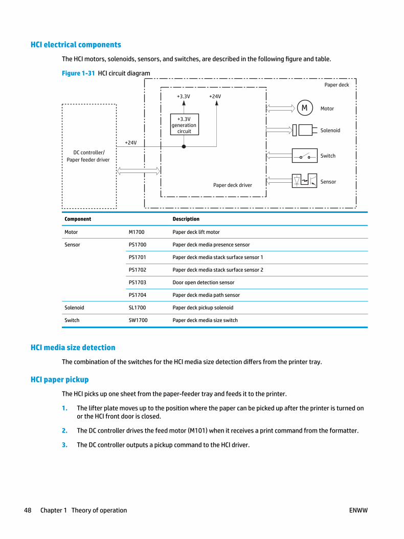
HCI electrical components
The HCI motors, solenoids, sensors, and switches, are described in the following figure and table.
Figure 1-31 HCI circuit diagram
M Motor
Solenoid
SensorPaper deck driver
SwitchDC controller/Paper feeder driver
Paper deck
+24V
+3.3Vgeneration
circuit
+3.3V +24V
Component Description
Motor M1700 Paper deck lift motor
Sensor PS1700 Paper deck media presence sensor
PS1701 Paper deck media stack surface sensor 1
PS1702 Paper deck media stack surface sensor 2
PS1703 Door open detection sensor
PS1704 Paper deck media path sensor
Solenoid SL1700 Paper deck pickup solenoid
Switch SW1700 Paper deck media size switch
HCI media size detection
The combination of the switches for the HCI media size detection differs from the printer tray.
HCI paper pickup
The HCI picks up one sheet from the paper-feeder tray and feeds it to the printer.
1. The lifter plate moves up to the position where the paper can be picked up after the printer is turned on or the HCI front door is closed.
2. The DC controller drives the feed motor (M101) when it receives a print command from the formatter.
3. The DC controller outputs a pickup command to the HCI driver.
48 Chapter 1 Theory of operation ENWW

4. The HCI driver turns on the PD pickup solenoid (SL1700) when it receives a pickup command. Accordingly the HCI pickup roller, HCI feed roller and HCI feed roller 1 rotate to pick up media in the HCI. (HCI pickup mechanism is the same way as that of the printer).
5. The HCI separation roller holds back any multiple-fed sheets and one sheet of media is fed in to the printer. (HCI multiple-feed prevention mechanism is the same way as that of the printer).
HCI multiple feed prevention
The HCI multiple-feed prevention for the paper feeder is operated in the same way as that of the printer base.
ENWW Input accessories 49
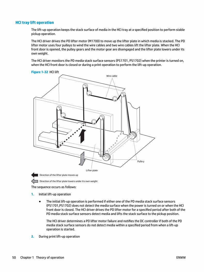
HCI tray lift operation
The lift-up operation keeps the stack surface of media in the HCI tray at a specified position to perform stable pickup operation.
The HCI driver drives the PD lifter motor (M1700) to move up the lifter plate in which media is stacked. The PD lifter motor uses four pulleys to wind the wire cables and two wire cables lift the lifter plate. When the HCI front door is opened, the pulley gears and the motor gear are disengaged and the lifter plate lowers under its own weight.
The HCI driver monitors the PD media stack surface sensors (PS1701, PS1702) when the printer is turned on, when the HCI front door is closed or during a print operation to perform the lift-up operation.
Figure 1-32 HCI lift
Direction of the lifter plate moves up
Direction of the lifter plate lowers under its own weight
Wire cable
Lifter plate
Pulle y
The sequence occurs as follows:
1. Initial lift-up operation
● The initial lift-up operation is performed if either one of the PD media stack surface sensors (PS1701,PS1702) does not detect the media surface when the power is turned on or when the HCI front door is closed. The HCI driver drives the PD lifter motor for a specified period after both of the PD media stack surface sensors detect media and lifts the stack surface to the pickup position.
The HCI driver determines a PD lifter motor failure and notifies the DC controller if both of the PD media stack surface sensors do not detect media within a specified period from when a lift-up operation is started.
2. During print lift-up operation
50 Chapter 1 Theory of operation ENWW

● The during print lift-up operation is performed when the media surface is lowered for a specified level due to a pickup operation. The HCI driver drives the PD lifter motor for a specified period and lifts the stack surface to the pickup position when the PD media stack surface sensor 1 (PS1701) detects media absence during a print operation.
3. Pickup retry lift-up operation
● The pickup retry lift-up operation is performed when the first pickup retry is failed to pick up media. The HCI driver drives the PD lifter motor for a specified period to lift the stack surface and performs second pickup retry.
HCI jam detection
The paper jam for the HCI is detected by the DC controller of the printer base.
ENWW Input accessories 51
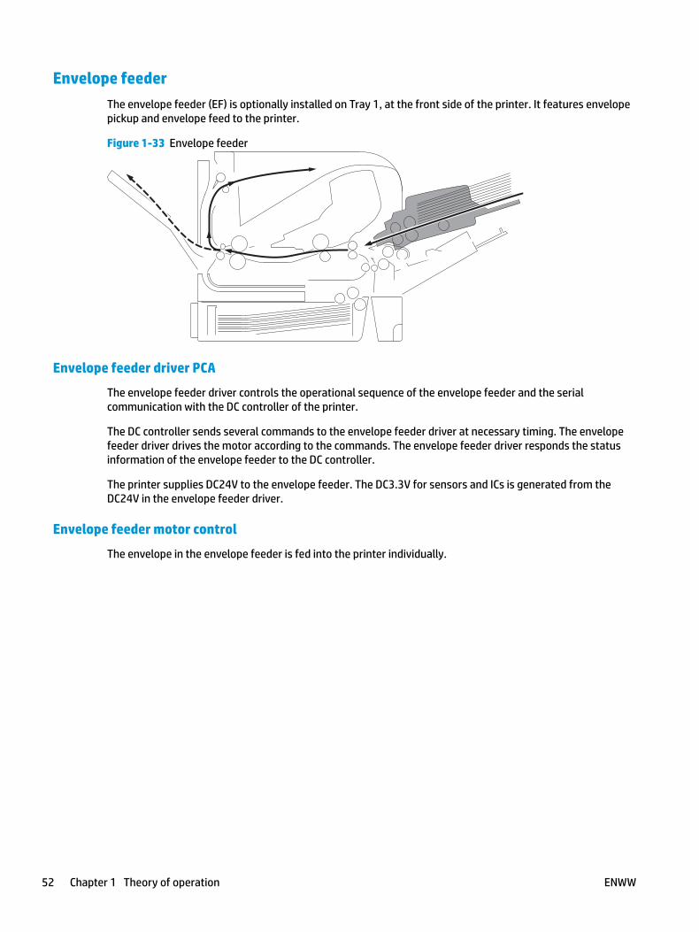
Envelope feederThe envelope feeder (EF) is optionally installed on Tray 1, at the front side of the printer. It features envelope pickup and envelope feed to the printer.
Figure 1-33 Envelope feeder
Envelope feeder driver PCA
The envelope feeder driver controls the operational sequence of the envelope feeder and the serial communication with the DC controller of the printer.
The DC controller sends several commands to the envelope feeder driver at necessary timing. The envelope feeder driver drives the motor according to the commands. The envelope feeder driver responds the status information of the envelope feeder to the DC controller.
The printer supplies DC24V to the envelope feeder. The DC3.3V for sensors and ICs is generated from the DC24V in the envelope feeder driver.
Envelope feeder motor control
The envelope in the envelope feeder is fed into the printer individually.
52 Chapter 1 Theory of operation ENWW
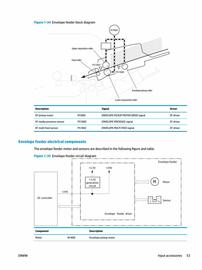
Figure 1-34 Envelope feeder block diagram
Envelope pickup roller
Upper separation roller
Lower separartion roller
Feed roller
Torquelimiter
M1800
PS1800
PS1802
Description Signal Driver
EF pickup motor M1800 ENVELOPE PICKUP MOTOR DRIVE signal EF driver
EF media presence sensor PS1800 ENVELOPE PRESENCE signal EF driver
EF multi feed sensor PS1802 ENVELOPE MULTI FEED signal EF driver
Envelope feeder electrical components
The envelope feeder motor and sensors are described in the following figure and table.
Figure 1-35 Envelope feeder circuit diagram
M Motor
Sensor
Envelope feeder driver
DC controller
Envelope feeder
+24V
+3.3Vgeneration
circuit
+3.3V +24V
Component Description
Motor M1800 Envelope pickup motor
ENWW Input accessories 53
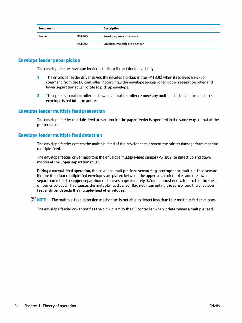
Component Description
Sensor PS1800 Envelope presence sensor
PS1802 Envelope multiple feed sensor
Envelope feeder paper pickup
The envelope in the envelope feeder is fed into the printer individually.
1. The envelope feeder driver drives the envelope pickup motor (M1800) when it receives a pickup command from the DC controller. Accordingly the envelope pickup roller, upper separation roller and lower separation roller rotate to pick up envelope.
2. The upper separation roller and lower separation roller remove any multiple-fed envelopes and one envelope is fed into the printer.
Envelope feeder multiple feed prevention
The envelope feeder multiple-feed prevention for the paper feeder is operated in the same way as that of the printer base.
Envelope feeder multiple feed detection
The envelope feeder detects the multiple-feed of the envelopes to prevent the printer damage from massive multiple-feed.
The envelope feeder driver monitors the envelope multiple-feed sensor (PS1802) to detect up and down motion of the upper separation roller.
During a normal-feed operation, the envelope multiple-feed sensor flag interrupts the multiple-feed sensor. If more than four multiple-fed envelopes are placed between the upper separation roller and the lower separation roller, the upper separation roller rises approximately 0.7mm (almost equivalent to the thickness of four envelopes). This causes the multiple-feed sensor flag not interrupting the sensor and the envelope feeder driver detects the multiple-feed of envelopes.
NOTE: The multiple-feed detection mechanism is not able to detect less than four multiple-fed envelopes.
The envelope feeder driver notifies the pickup jam to the DC controller when it determines a multiple feed.
54 Chapter 1 Theory of operation ENWW
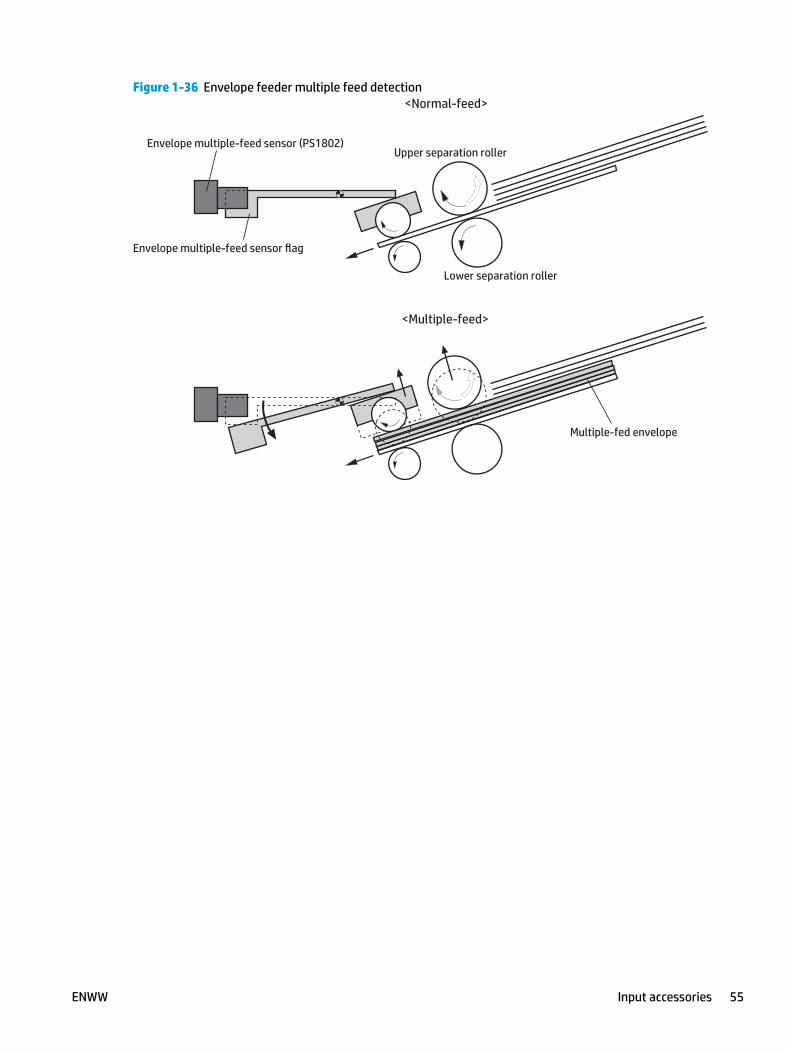
Figure 1-36 Envelope feeder multiple feed detection<Normal-feed>
<Multiple-feed>
Envelope multiple-feed sensor flag
Envelope multiple-feed sensor (PS1802)Upper separation roller
Multiple-fed envelope
Lower separation roller
ENWW Input accessories 55
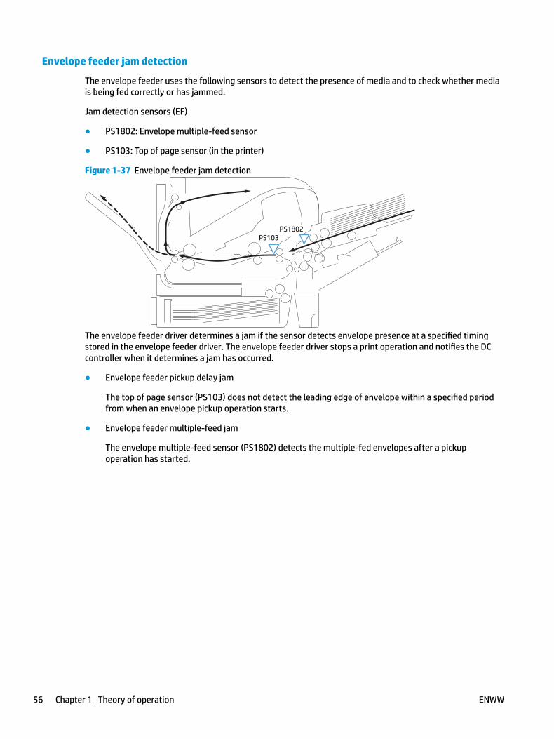
Envelope feeder jam detection
The envelope feeder uses the following sensors to detect the presence of media and to check whether media is being fed correctly or has jammed.
Jam detection sensors (EF)
● PS1802: Envelope multiple-feed sensor
● PS103: Top of page sensor (in the printer)
Figure 1-37 Envelope feeder jam detection
PS1802PS103
The envelope feeder driver determines a jam if the sensor detects envelope presence at a specified timing stored in the envelope feeder driver. The envelope feeder driver stops a print operation and notifies the DC controller when it determines a jam has occurred.
● Envelope feeder pickup delay jam
The top of page sensor (PS103) does not detect the leading edge of envelope within a specified period from when an envelope pickup operation starts.
● Envelope feeder multiple-feed jam
The envelope multiple-feed sensor (PS1802) detects the multiple-fed envelopes after a pickup operation has started.
56 Chapter 1 Theory of operation ENWW
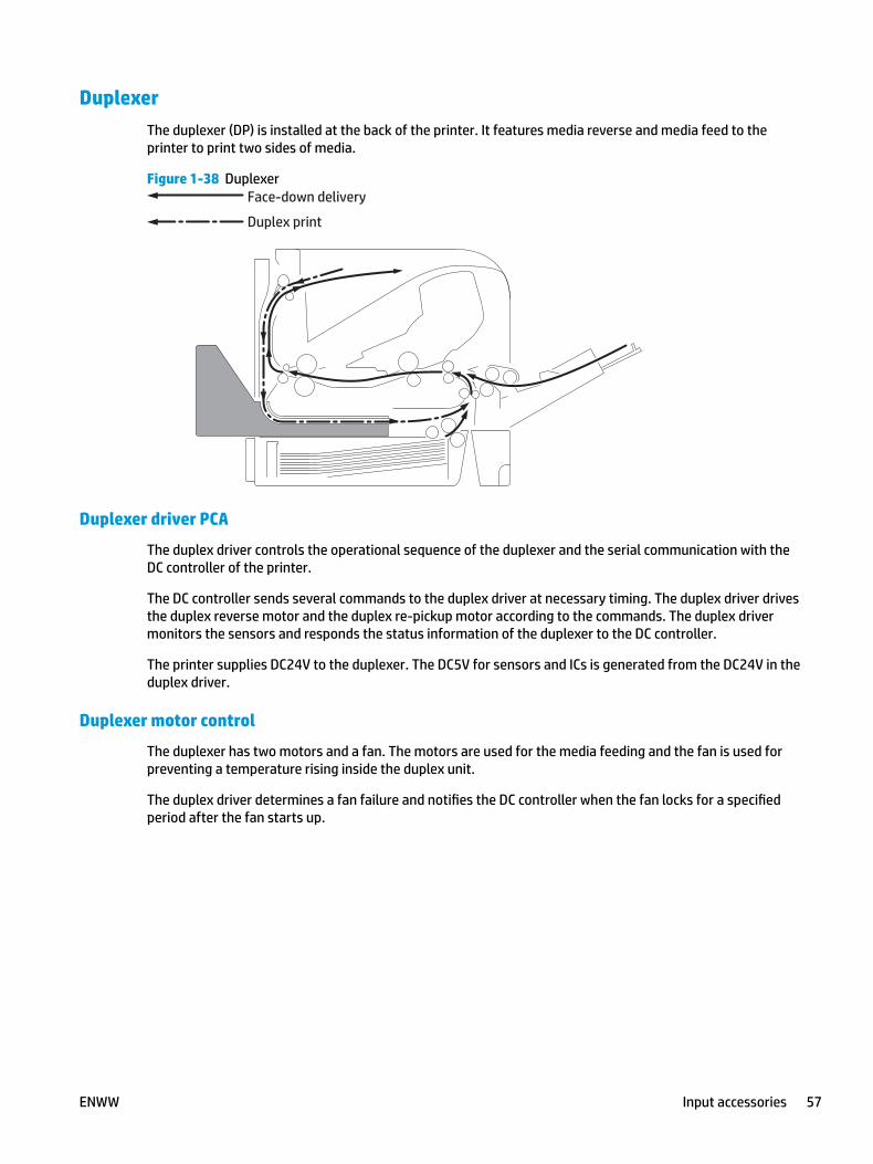
DuplexerThe duplexer (DP) is installed at the back of the printer. It features media reverse and media feed to the printer to print two sides of media.
Figure 1-38 DuplexerFace-down delivery
Duplex print
Duplexer driver PCA
The duplex driver controls the operational sequence of the duplexer and the serial communication with the DC controller of the printer.
The DC controller sends several commands to the duplex driver at necessary timing. The duplex driver drives the duplex reverse motor and the duplex re-pickup motor according to the commands. The duplex driver monitors the sensors and responds the status information of the duplexer to the DC controller.
The printer supplies DC24V to the duplexer. The DC5V for sensors and ICs is generated from the DC24V in the duplex driver.
Duplexer motor control
The duplexer has two motors and a fan. The motors are used for the media feeding and the fan is used for preventing a temperature rising inside the duplex unit.
The duplex driver determines a fan failure and notifies the DC controller when the fan locks for a specified period after the fan starts up.
ENWW Input accessories 57
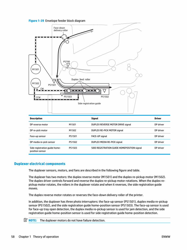
Figure 1-39 Envelope feeder block diagram
M1502
M1501
PS1501
PS1502PS1503
PS700
Duplex feed roller
Face-downdelivery roller
CW
CCW
Side registration guide
Description Signal Driver
DP reverse motor M1501 DUPLEX REVERSE MOTOR DRIVE signal DP driver
DP re-pick motor M1502 DUPLEX RE-PICK MOTOR signal DP driver
Face-up sensor PS1501 FACE-UP signal DP driver
DP media re-pick sensor PS1502 DUPLEX MEDIA RE-PICK signal DP driver
Side registration guide home-position sensor
PS1503 SIDE REGISTRATION GUIDE HOMEPOSITION signal DP driver
Duplexer electrical components
The duplexer sensors, motors, and fans are described in the following figure and table.
The duplexer has two motors: the duplex reverse motor (M1501) and the duplex re-pickup motor (M1502). The duplex driver controls forward and reverse the duplex re‑pickup motor rotations. When the duplex re-pickup motor rotates, the rollers in the duplexer rotate and when it reverses, the side registration guide moves.
The duplex reverse motor rotates or reverses the face-down delivery roller of the printer.
In addition, the duplexer has three photo interrupters: the face-up sensor (PS1501), duplex media re‑pickup sensor (PS1502), and the side registration guide home-position sensor (PS1503). The face-up sensor is used for face-up tray open detection, the duplex media re-pickup sensor is used for jam detection, and the side registration guide home-position sensor is used for side registration guide home-position detection.
NOTE: The duplexer motors do not have failure detection.
58 Chapter 1 Theory of operation ENWW
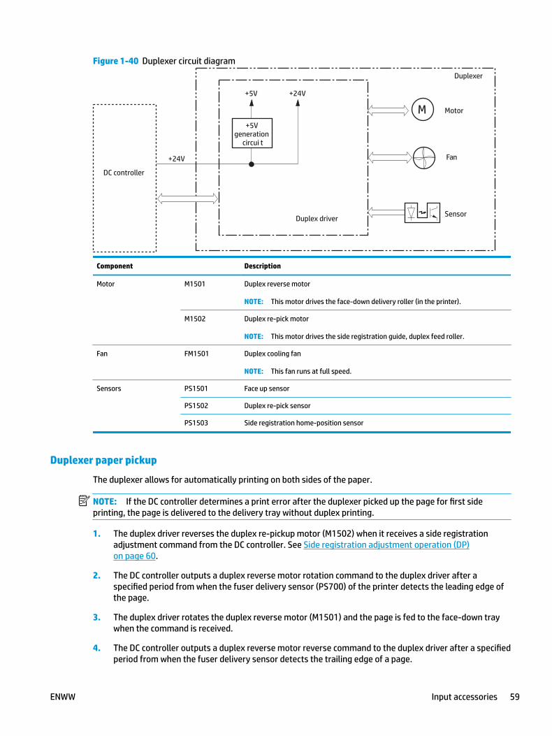
Figure 1-40 Duplexer circuit diagram
M Motor
Sensor
DC controller
+24V
+5Vgeneration
circui t
+5V +24V
Duplex driver
Duplexer
Fan
Component Description
Motor M1501 Duplex reverse motor
NOTE: This motor drives the face-down delivery roller (in the printer).
M1502 Duplex re-pick motor
NOTE: This motor drives the side registration guide, duplex feed roller.
Fan FM1501 Duplex cooling fan
NOTE: This fan runs at full speed.
Sensors PS1501 Face up sensor
PS1502 Duplex re-pick sensor
PS1503 Side registration home-position sensor
Duplexer paper pickup
The duplexer allows for automatically printing on both sides of the paper.
NOTE: If the DC controller determines a print error after the duplexer picked up the page for first side printing, the page is delivered to the delivery tray without duplex printing.
1. The duplex driver reverses the duplex re-pickup motor (M1502) when it receives a side registration adjustment command from the DC controller. See Side registration adjustment operation (DP) on page 60.
2. The DC controller outputs a duplex reverse motor rotation command to the duplex driver after a specified period from when the fuser delivery sensor (PS700) of the printer detects the leading edge of the page.
3. The duplex driver rotates the duplex reverse motor (M1501) and the page is fed to the face-down tray when the command is received.
4. The DC controller outputs a duplex reverse motor reverse command to the duplex driver after a specified period from when the fuser delivery sensor detects the trailing edge of a page.
ENWW Input accessories 59
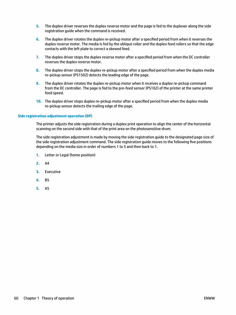
5. The duplex driver reverses the duplex reverse motor and the page is fed to the duplexer along the side registration guide when the command is received.
6. The duplex driver rotates the duplex re-pickup motor after a specified period from when it reverses the duplex reverse motor. The media is fed by the oblique roller and the duplex feed rollers so that the edge contacts with the left plate to correct a skewed feed.
7. The duplex driver stops the duplex reverse motor after a specified period from when the DC controller reverses the duplex reverse motor.
8. The duplex driver stops the duplex re-pickup motor after a specified period from when the duplex media re-pickup sensor (PS1502) detects the leading edge of the page.
9. The duplex driver rotates the duplex re-pickup motor when it receives a duplex re-pickup command from the DC controller. The page is fed to the pre-feed sensor (PS102) of the printer at the same printer feed speed.
10. The duplex driver stops duplex re-pickup motor after a specified period from when the duplex media re‑pickup sensor detects the trailing edge of the page.
Side registration adjustment operation (DP)
The printer adjusts the side registration during a duplex print operation to align the center of the horizontal scanning on the second side with that of the print area on the photosensitive drum.
The side registration adjustment is made by moving the side registration guide to the designated page size of the side registration adjustment command. The side registration guide moves to the following five positions depending on the media size in order of numbers 1 to 5 and then back to 1.
1. Letter or Legal (home position)
2. A4
3. Executive
4. B5
5. A5
60 Chapter 1 Theory of operation ENWW
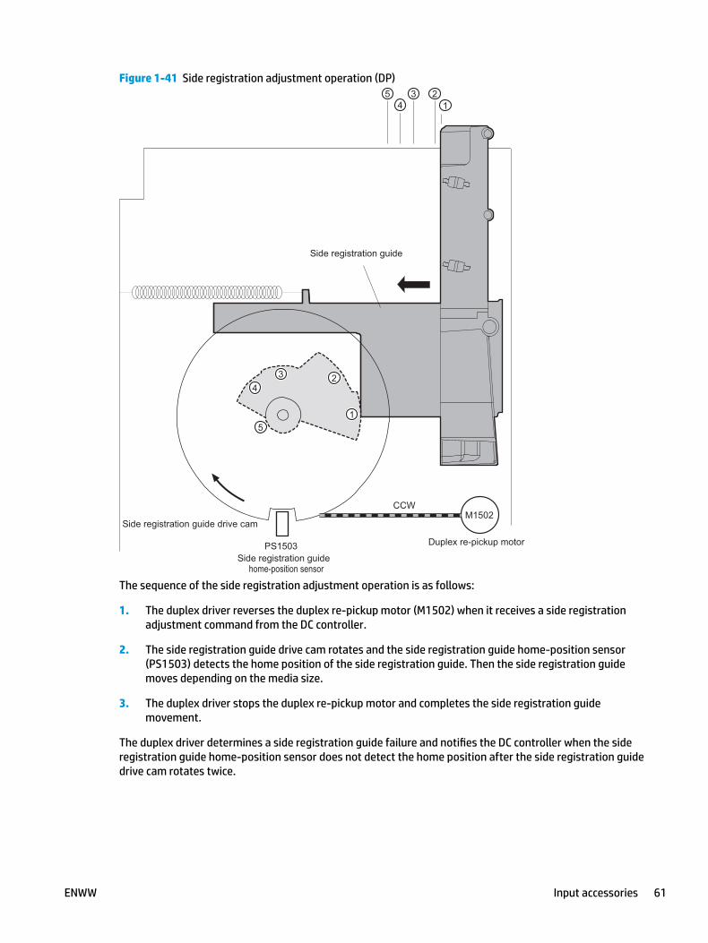
Figure 1-41 Side registration adjustment operation (DP)
home-position sensor
The sequence of the side registration adjustment operation is as follows:
1. The duplex driver reverses the duplex re-pickup motor (M1502) when it receives a side registration adjustment command from the DC controller.
2. The side registration guide drive cam rotates and the side registration guide home-position sensor (PS1503) detects the home position of the side registration guide. Then the side registration guide moves depending on the media size.
3. The duplex driver stops the duplex re-pickup motor and completes the side registration guide movement.
The duplex driver determines a side registration guide failure and notifies the DC controller when the side registration guide home-position sensor does not detect the home position after the side registration guide drive cam rotates twice.
ENWW Input accessories 61
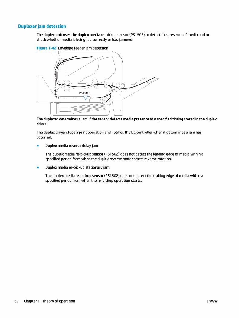
Duplexer jam detection
The duplex unit uses the duplex media re-pickup sensor (PS1502) to detect the presence of media and to check whether media is being fed correctly or has jammed.
Figure 1-42 Envelope feeder jam detection
PS1502
The duplexer determines a jam if the sensor detects media presence at a specified timing stored in the duplex driver.
The duplex driver stops a print operation and notifies the DC controller when it determines a jam has occurred.
● Duplex media reverse delay jam
The duplex media re-pickup sensor (PS1502) does not detect the leading edge of media within a specified period from when the duplex reverse motor starts reverse rotation.
● Duplex media re-pickup stationary jam
The duplex media re-pickup sensor (PS1502) does not detect the trailing edge of media within a specified period from when the re-pickup operation starts.
62 Chapter 1 Theory of operation ENWW

2 Solve problems
● For additional service and support
● Solve problems checklist
● Troubleshooting process
● Tools for troubleshooting
● Solve image-quality problems
● Clean the printer
● Solve paper handling problems
● Clear paper jams
● Solve performance problems
● Solve connectivity problems
● Service mode functions
● Firmware upgrades
ENWW 63

For additional service and supportHP service personnel, go to the Service Access Work Bench (SAW) at http://h41302.www4.hp.com/km/saw/home.do.
Channel partners, go to HP Channel Services Network (CSN) at https://h30125.www3.hp.com/hpcsn.
● To access HP PartSurfer information from any mobile device, go to http://partsurfermobile.hp.com/ or scan the Quick Response (QR) code below.
● Install and configure
● Printer specifications
● Up to date control-panel message (CPMD) troubleshooting
● Solutions for printer issues and emerging issues
● Remove and replace part instructions and videos
● Service advisories
● Warranty & regulatory information
64 Chapter 2 Solve problems ENWW
Solve problems checklist● Solve problems checklist
● Print the configuration page
● Print menu map
● Print current settings pages
● Print event log
● Pre-boot menu options
Solve problems checklistIf the printer is not correctly functioning, complete the steps (in the order given) in the following checklist. If the printer fails a checklist step, follow the corresponding troubleshooting suggestions for that step. If a checklist step resolves the problem, skip the remaining checklist items.
1. If the control panel is blank or black, check the following before proceeding:
❑ Check to make sure that the printer is not in Sleep mode (tap the touchscreen control panel or press a button on the LCD control panel).
❑ Check the power cable.
❑ Check that the power is turned on.
❑ Make sure that the line voltage is correct for the printer power configuration. (See the label that is on the back of the printer for voltage requirements.) If a power strip is in use, and its voltage is not within specifications, connect the printer directly into the electrical outlet. If it is already connected into the outlet, try a different outlet.
If the control panel is not responding to touch (M605x and M606x models), or if it appears black or blank, try the following:
a. Turn the printer power off, and then on again.
b. Try upgrading the firmware. If the firmware upgrade fails to resolve the problem, and the printer still freezes while in Sleep mode, elevate the case after collecting the following info:
● Try printing to the printer from a host computer. Does the printer print a page?
● Is the printer HP Embedded Web Server (EWS) accessible?
● Turn the printer power off, and then on again. Save the printer diagnostic file.
To save diagnostic files from a touchscreen control panel
1. From the Home screen on the printer control panel, scroll to and touch the Backup/Restore button.
2. Open the following menu:
● Retrieve Diagnostic Data
3. Use the down arrow button to scroll to the desired data-saving option, and then touch the Save button.
ENWW Solve problems checklist 65
To save diagnostic files from a LCD control panel
1. From the Home screen on the printer control panel, use the down arrow button to scroll to Backup/Restore and then press the OK button.
2. Use the down arrow button to scroll to Retrieve Diagnostic Data, and then press the OK button.
3. Use the down arrow button to scroll to the desired data saving options, and then press the OK button.
c. If the printer did not freeze while in Sleep mode, verify that the control panel is correctly functioning by accessing the control panel diagnostics. See the Control-panel checks section of the printer problem solving manual.
TIP: The LED on the formatter will blink if the control panel is not detected or the cables are not properly seated.
If the control panel does not respond to the diagnostic button, try the following:
● Turn the printer power off.
● Reseat the cable connections on the bottom of the control-panel assembly.
● Turn the printer power on, and then check for functionality of the control-panel.
d. Check the control-panel connectors at the control panel and at the formatter.
e. If the error persists, replace the control-panel assembly.
2. The control panel should indicate a Ready, Paused, or Sleep mode on status. If an error message displays, resolve the error.
● Use the Power-on checks section in the printer troubleshooting service manual to solve the problem.
3. For network connection errors, check the cables.
a. Check the network cable connections between the printer and the computer or network port. Make sure that the connections are secure.
NOTE: The network LEDs should be illuminated and flashing.
b. Make sure that the cables are not faulty by trying different cables, if possible.
c. Check the network connection.
4. Print a configuration page. If the printer is connected to a network, an HP Jetdirect page also prints.
Print a configuration page from a touchscreen control panel
a. From the Home screen on the printer control panel, scroll to and touch the Administration button.
b. Open the following menus:
● Reports
● Configuration/Status Pages
● Configuration Page
66 Chapter 2 Solve problems ENWW
c. Touch Configuration Page to select it.
TIP: Multiple report pages can be selected, and then printed together.
d. Touch the Print button to print the pages.
Print a configuration page from a LCD control panel
a. From the Home screen on the printer control panel, use the to scroll to Administration, and then press the OK button.
b. If necessary, use the down arrow button to scroll to Reports, and then press the OK button.
c. If necessary, use the down arrow button to scroll to Configuration/Status Pages, and then press the OK button.
d. Use the down arrow button to scroll to Configuration page, and then press the OK button to select it.
e. Use the up arrow button to scroll to Print, and then press the OK button to print the pages.
TIP: Multiple report pages can be selected, and then printed together.
● If the pages do not print, check that at least one tray contains paper.
TIP: Make sure that the selected paper size and type meet HP specifications. Also open the Trays menu on the printer control panel and verify that the tray is configured correctly for the paper type and size.
● If the page jams in the printer, follow the instructions on the control panel to clear the jam.
● If the page does not print correctly, the problem is with the printer hardware.
● If the page prints correctly, the printer hardware is working. The problem is with the host computer, with the print driver, or with the program.
5. Print a supplies status page and then check that the maintenance items below are not at their end-of-life.
TIP: If a maintenance item needs to be replaced, order the part number provided below.
Print a supplies status page from a touchscreen control panel
a. From the Home screen on the printer control panel, scroll to and touch the Administration button.
b. Open the following menus:
● Reports
● Configuration/Status Pages
● Supplies Status Page
c. Touch the Print button to print the page, and then check the maintenance items (listed below in this step).
TIP: Multiple report pages can be selected, and then printed together.
ENWW Solve problems checklist 67
Print a supplies status page from a LCD control panel
a. From the Home screen on the printer control panel, use the down arrow button to scroll to Administration, and then press the OK button.
b. If necessary, use the down arrow button to scroll to Reports, and then press the OK button.
c. If necessary, use the down arrow button to scroll to Configuration/Status Pages, and then press the OK button.
d. Use the down arrow button to scroll to Supplies Status Page, and then press the OK button to select it.
e. Use the up arrow button to scroll to Print, and then press the OK button to print the page, and then check the maintenance items (listed below in this step).
TIP: Multiple report pages can be selected, and then printed together.
NOTE: HP long-life consumables and maintenance kit life specifications are estimations. Actual individual life/yield during normal use varies depending on usage, environment, media, and other factors. Estimated life is not an implied guarantee or warrantable.
● Fuser kit; estimated life: 225,000 pages
◦ F2G76-67901 (110V)
◦ F2G77-67901 (220V)
6. Verify that the correct print driver for this printer is installed. Check the program to make sure that the print driver for this printer is used. The print driver is on the CD that came with the printer, or can be downloaded from this Web site: www.hp.com/support/ljM604, www.hp.com/support/ljM605, www.hp.com/support/ljM606.
7. Print a short document from a different program that has worked in the past. If this solution works, the problem is with the program. If this solution does not work (the document does not print), complete these steps:
a. Try printing the job from another computer that has the printer software installed.
b. If the printer is connected to the network, connect the printer directly to a host computer with a USB cable. Redirect the printer to the correct port, or reinstall the software (make sure to select the new connection type).
Print the configuration page
NOTE: Depending on the model, up to three pages print when printing a configuration page. In addition to the main configuration page, the HP embedded Jetdirect configuration pages print.
Print the configuration page from a touchscreen control panel
1. From the Home screen on the printer control panel, scroll to and touch the Administration button.
2. Open the following menus:
● Reports
● Configuration/Status Pages
68 Chapter 2 Solve problems ENWW
3. Touch Configuration Page to select it.
4. Touch the Print button to print the pages.
TIP: Multiple report pages can be selected, and then printed together.
Print the configuration page from a LCD control panel
1. From the Home screen on the printer control panel, use the down arrow button to scroll to Administration, and then press the OK button.
2. Open the following menus:
● Reports
● Configuration/Status Pages
3. Use the down arrow button to scroll to Configuration Page, and then press the OK button to select it.
4. Use the up arrow button to scroll to Print, and then press the OK button to print the pages.
TIP: Multiple report pages can be selected, and then printed together.
Print menu mapTo more easily navigate individual settings, print a report of the complete Administration menu.
Print the menu map from a touchscreen control panel
1. From the Home screen on the printer control panel, scroll to and touch the Administration button.
2. Open the following menus:
● Reports
● Configuration/Status Pages
3. Select the Administration Menu Map option.
4. Touch the Print button to print the report.
TIP: Multiple report pages can be selected, and then printed together.
Print the menu map from a LCD control panel
1. From the Home screen on the printer control panel, use the down arrow button to scroll to Administration, and then press the OK button.
2. Open the following menus:
● Reports
● Configuration/Status Pages
3. Use the down arrow button to scroll to Administration Menu Map, and then press the OK button to select it.
4. Use the up arrow button to scroll to Print, and then press the OK button to print the pages.
ENWW Solve problems checklist 69

TIP: Multiple report pages can be selected, and then printed together.
Print current settings pagesPrinting the current settings page provides a map of the user configurable settings that might be helpful in the troubleshooting process.
Print the current settings page from a touchscreen control panel
1. From the Home screen on the printer control panel, scroll to and touch the Administration button.
2. Open the following menus:
● Reports
● Configuration/Status Pages
3. Select the Current Settings Page option.
4. Touch the Print button to print the report.
TIP: Multiple report pages can be selected, and then printed together.
Print the current settings page from a LCD control panel
1. From the Home screen on the printer control panel, use the down arrow button to scroll to Administration, and then press the OK button.
2. Open the following menus:
● Reports
● Configuration/Status Pages
3. Use the down arrow button to scroll to Current Settings Page, and then press the OK button to select it.
4. Use the up arrow button to scroll to Print, and then press the OK button to print the pages.
TIP: Multiple report pages can be selected, and then printed together.
Print event logPrinting the event log might be helpful in the troubleshooting process. For more information, see the Interpret control-panel messages and event log entries section in the printer troubleshooting manual.
Print the event log from the Administration menu from a touchscreen control panel
1. From the Home screen on the printer control panel, scroll to and touch the Administration button.
2. Open the following menus:
● Troubleshooting
● Event Log
3. The event log displays on the screen. To print it, touch the Print button.
70 Chapter 2 Solve problems ENWW

Print the event log from the Administration menu from a LCD control panel
1. From the Home screen on the printer control panel, use the down arrow button to scroll to Administration, and then press the OK button.
2. Use the down arrow button to scroll to Troubleshooting, and then press the OK button.
3. If necessary, use the down arrow button to scroll to Print Event Log, and then press the OK button to print the page.
Print the event log from the Service menu from a touchscreen control panel
1. From the Home screen on the printer control panel, scroll to and touch the Device Maintenance button.
2. Open the Service menu.
3. On the sign-in screen, select the Service Access Code option from the drop-down list.
4. Enter the following service access code for the printer:
● 04060615 (M606)
● 04060515 (M605)
● 04060415 (M604)
5. Touch the Print Event Log item.
Print the event log from the Service menu from a LCD control panel
1. From the Home screen on the printer control panel, use the down arrow button to scroll to Device Maintenance, and then press the OK button.
2. Use the down arrow button to scroll to Service, and then press the OK button.
3. On the sign-in screen, use the down arrow button to scroll to Service Access Code option and then press the OK button.
4. Enter the following service access code for the printer:
● 04060615 (M606)
● 04060515 (M605)
● 04060415 (M604)
5. If necessary, use the down arrow button to scroll to Print Event Log, and then press the OK button to print the page.
Clear the event log from a touchscreen control panel
1. From the Home screen on the printer control panel, scroll to and touch the Device Maintenance button.
2. Open the Service menu.
3. On the sign-in screen, select the Service Access Code option from the drop-down list.
4. Enter the following service access code for the printer:
ENWW Solve problems checklist 71

● 04060615 (M606)
● 04060515 (M605)
● 04060415 (M604)
5. Select the Clear Event Log item, and then touch the OK button.
Clear the event log from a LCD control panel
1. From the Home screen on the printer control panel, use the down arrow button to scroll to Device Maintenance, and then press the OK button.
2. Use the down arrow button to scroll to Service, and then press the OK button.
3. On the sign-in screen, use the down arrow button to scroll to Service Access Code option and then press the OK button.
4. Enter the following service access code for the printer:
● 04060615 (M606)
● 04060515 (M605)
● 04060415 (M604)
5. If necessary, use the down arrow button to scroll to Clear Event Log, and then press the OK button.
72 Chapter 2 Solve problems ENWW
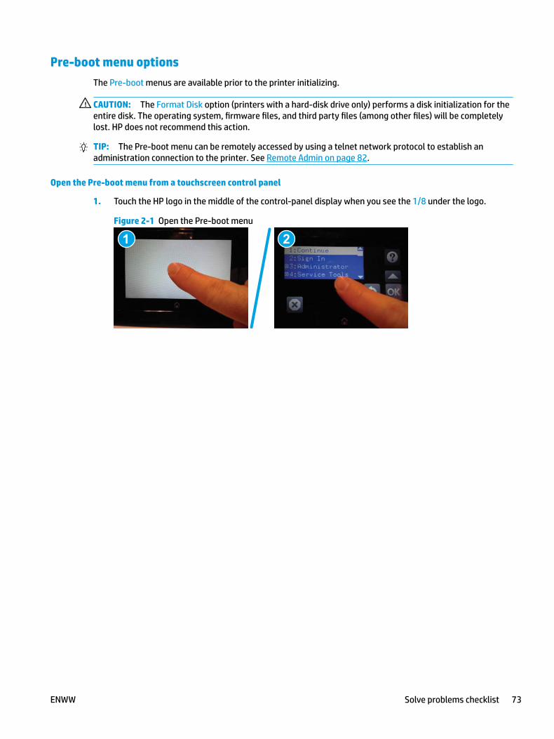
Pre-boot menu optionsThe Pre-boot menus are available prior to the printer initializing.
CAUTION: The Format Disk option (printers with a hard-disk drive only) performs a disk initialization for the entire disk. The operating system, firmware files, and third party files (among other files) will be completely lost. HP does not recommend this action.
TIP: The Pre-boot menu can be remotely accessed by using a telnet network protocol to establish an administration connection to the printer. See Remote Admin on page 82.
Open the Pre-boot menu from a touchscreen control panel
1. Touch the HP logo in the middle of the control-panel display when you see the 1/8 under the logo.
Figure 2-1 Open the Pre-boot menu
1 2
ENWW Solve problems checklist 73
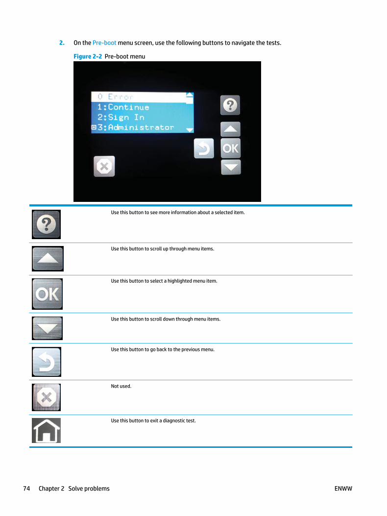
2. On the Pre-boot menu screen, use the following buttons to navigate the tests.
Figure 2-2 Pre-boot menu
Use this button to see more information about a selected item.
Use this button to scroll up through menu items.
Use this button to select a highlighted menu item.
Use this button to scroll down through menu items.
Use this button to go back to the previous menu.
Not used.
Use this button to exit a diagnostic test.
74 Chapter 2 Solve problems ENWW

3. Use the arrow buttons on the touchscreen to navigate the Pre-boot menu.
4. Touch the OK button to select a menu item.
Open the Pre-boot menu from a LCD control panel
1. Press the Cancel button when you see the 1/8 under the logo.
2. Use the arrow buttons on the control panel to navigate the Pre-boot menu.
3. Press the OK button to select a menu item.
Cold reset using the Pre-boot menu from a touchscreen control panel
CAUTION: This procedure resets all printer configurations and settings to factory defaults (customer configurations and settings are lost).
1. Touch the HP logo in the middle of the control-panel display when you see the 1/8 under the logo.
Figure 2-3 Open the Pre-boot menu
1 2
2. Use the button to highlight the +3:Administrator item, and then touch the OK button.
3. Use the button to highlight the +8:Startup Options item, and then touch the OK button.
4. Use the button to highlight the 2 Cold Reset item, and then touch the OK button to select it.
5. Touch the Home button to return to the main Pre-boot menu and highlight the 1:Continue item, and then touch the OK button.
NOTE: The printer will initialize.
Cold reset using the Pre-boot menu from a LCD control panel
CAUTION: This procedure resets all printer configurations and settings to factory defaults (customer configurations and settings are lost).
1. Press the Cancel button when you see the 1/8 under the logo.
2. Use the down arrow button to highlight the +3:Administrator item, and then press the OK button.
3. Use the down arrow button to highlight the +8:Startup Options item, and then press the OK button.
4. Use the down arrow button to highlight the 2 Cold Reset item, and then press the OK button to select it.
5. Touch the Home button to return to the main Pre-boot menu and highlight the 1:Continue item, and then touch the OK button.
ENWW Solve problems checklist 75
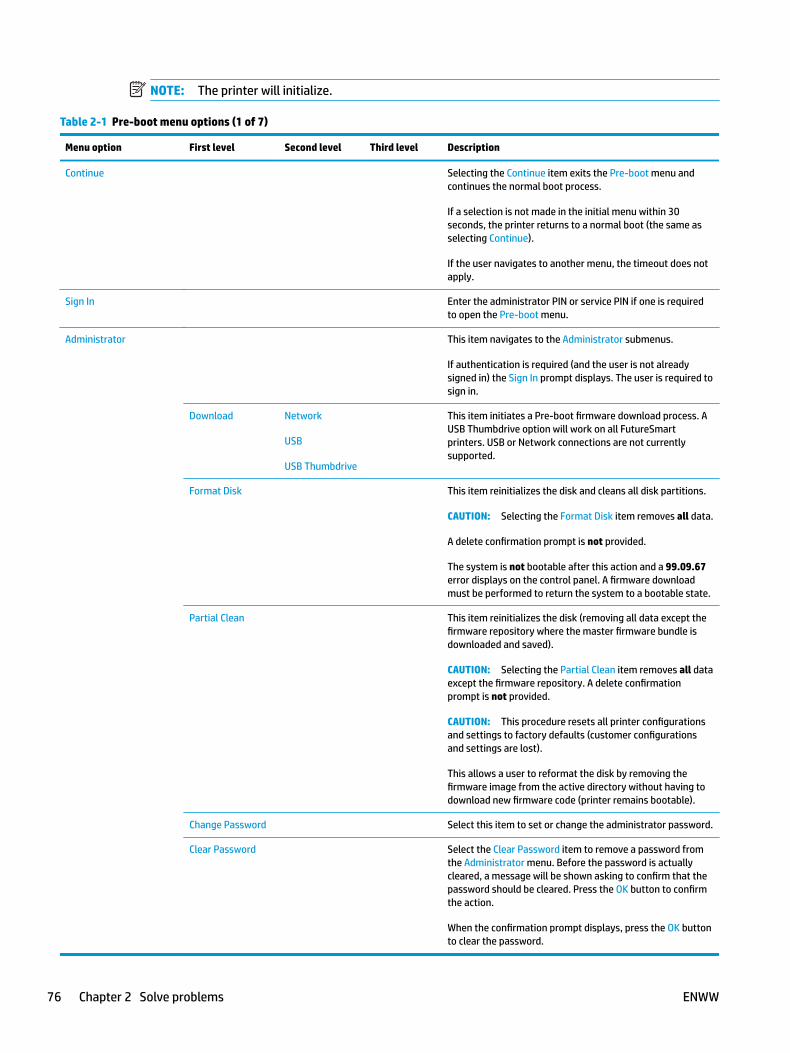
NOTE: The printer will initialize.
Table 2-1 Pre-boot menu options (1 of 7)
Menu option First level Second level Third level Description
Continue Selecting the Continue item exits the Pre-boot menu and continues the normal boot process.
If a selection is not made in the initial menu within 30 seconds, the printer returns to a normal boot (the same as selecting Continue).
If the user navigates to another menu, the timeout does not apply.
Sign In Enter the administrator PIN or service PIN if one is required to open the Pre-boot menu.
Administrator This item navigates to the Administrator submenus.
If authentication is required (and the user is not already signed in) the Sign In prompt displays. The user is required to sign in.
Download Network
USB
USB Thumbdrive
This item initiates a Pre-boot firmware download process. A USB Thumbdrive option will work on all FutureSmart printers. USB or Network connections are not currently supported.
Format Disk This item reinitializes the disk and cleans all disk partitions.
CAUTION: Selecting the Format Disk item removes all data.
A delete confirmation prompt is not provided.
The system is not bootable after this action and a 99.09.67 error displays on the control panel. A firmware download must be performed to return the system to a bootable state.
Partial Clean This item reinitializes the disk (removing all data except the firmware repository where the master firmware bundle is downloaded and saved).
CAUTION: Selecting the Partial Clean item removes all data except the firmware repository. A delete confirmation prompt is not provided.
CAUTION: This procedure resets all printer configurations and settings to factory defaults (customer configurations and settings are lost).
This allows a user to reformat the disk by removing the firmware image from the active directory without having to download new firmware code (printer remains bootable).
Change Password Select this item to set or change the administrator password.
Clear Password Select the Clear Password item to remove a password from the Administrator menu. Before the password is actually cleared, a message will be shown asking to confirm that the password should be cleared. Press the OK button to confirm the action.
When the confirmation prompt displays, press the OK button to clear the password.
76 Chapter 2 Solve problems ENWW

Table 2-2 Pre-boot menu options (2 of 7)
Menu option First level Second level Third level Description
Administrator
(continued)
Manage Disk Clear disk Select the Clear disk item to enable using an external device for job storage. Job storage is normally enabled only for the Boot device. This will be grayed out unless the 99.09.68 error is displayed.
Lock Disk Select the Lock Disk item to lock (mate) a new secure disk to this printer.
The secure disk already locked to this printer will remain accessible to this printer. Use this function to have more than one encrypted disk accessible by the printer when using them interchangeably.
The data stored on the secure disk locked to this printer always remains accessible to this printer.
Leave Unlocked Select the Leave Unlocked item to use a new secure disk in an unlocked mode for a single service event. The secure disk that is already locked to this printer will remain accessible to this printer and uses the old disk's encryption password with the new disk.
The secure disk that is already locked to this printer remains accessible to this printer.
Clear Disk Pwd Select the Clear Disk Pwd item to continue using the non-secure disk and clear the password associated with the yet-to-be installed secure disk.
CAUTION: Data on the missing secure disk will be permanently inaccessible.
Retain Password Select the Retain Password item to use the non-secure disk for this session only, and then search for the missing secure disk in future sessions.
Boot Device Secure Erase Select the Secure Erase item to erase all of the data on the disk and unlock it if required.
This might take a long time.
NOTE: The system will be unusable until the system files are reinstalled. The ATA secure-erase command is a one-pass overwrite, which erases the entire disk including firmware. The disk remains an encrypted disk.
Erase/Unlock Select the Erase/Unlock item to cryptographically erase all data on the disk and unlock the disk to allow a user to gain access to it from any printer.
NOTE: The system will be unusable until the system files are reinstalled. It erases the encryption key. The encryption key is erased, so the disk becomes a non-encrypted disk.
Get Status This item provides disk status information if any is available.
ENWW Solve problems checklist 77
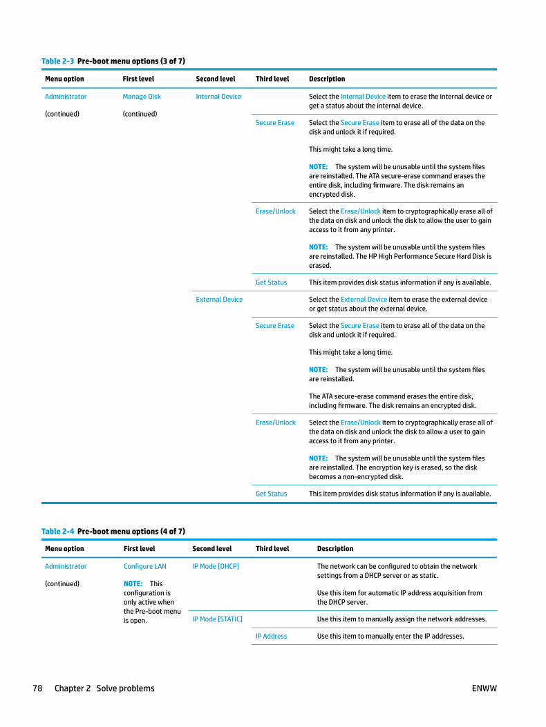
Table 2-3 Pre-boot menu options (3 of 7)
Menu option First level Second level Third level Description
Administrator
(continued)
Manage Disk
(continued)
Internal Device Select the Internal Device item to erase the internal device or get a status about the internal device.
Secure Erase Select the Secure Erase item to erase all of the data on the disk and unlock it if required.
This might take a long time.
NOTE: The system will be unusable until the system files are reinstalled. The ATA secure-erase command erases the entire disk, including firmware. The disk remains an encrypted disk.
Erase/Unlock Select the Erase/Unlock item to cryptographically erase all of the data on disk and unlock the disk to allow the user to gain access to it from any printer.
NOTE: The system will be unusable until the system files are reinstalled. The HP High Performance Secure Hard Disk is erased.
Get Status This item provides disk status information if any is available.
External Device Select the External Device item to erase the external device or get status about the external device.
Secure Erase Select the Secure Erase item to erase all of the data on the disk and unlock it if required.
This might take a long time.
NOTE: The system will be unusable until the system files are reinstalled.
The ATA secure-erase command erases the entire disk, including firmware. The disk remains an encrypted disk.
Erase/Unlock Select the Erase/Unlock item to cryptographically erase all of the data on disk and unlock the disk to allow a user to gain access to it from any printer.
NOTE: The system will be unusable until the system files are reinstalled. The encryption key is erased, so the disk becomes a non-encrypted disk.
Get Status This item provides disk status information if any is available.
Table 2-4 Pre-boot menu options (4 of 7)
Menu option First level Second level Third level Description
Administrator
(continued)
Configure LAN
NOTE: This configuration is only active when the Pre-boot menu is open.
IP Mode [DHCP] The network can be configured to obtain the network settings from a DHCP server or as static.
Use this item for automatic IP address acquisition from the DHCP server.
IP Mode [STATIC] Use this item to manually assign the network addresses.
IP Address Use this item to manually enter the IP addresses.
78 Chapter 2 Solve problems ENWW
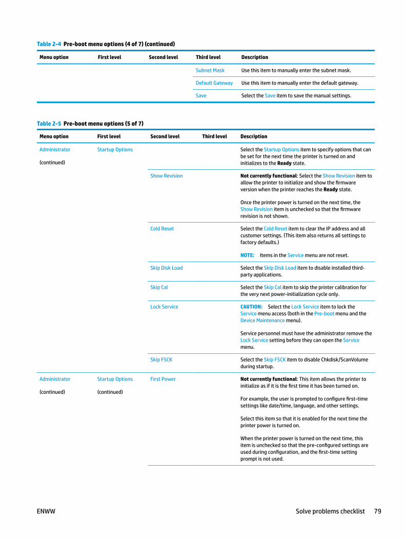
Table 2-4 Pre-boot menu options (4 of 7) (continued)
Menu option First level Second level Third level Description
Subnet Mask Use this item to manually enter the subnet mask.
Default Gateway Use this item to manually enter the default gateway.
Save Select the Save item to save the manual settings.
Table 2-5 Pre-boot menu options (5 of 7)
Menu option First level Second level Third level Description
Administrator
(continued)
Startup Options Select the Startup Options item to specify options that can be set for the next time the printer is turned on and initializes to the Ready state.
Show Revision Not currently functional: Select the Show Revision item to allow the printer to initialize and show the firmware version when the printer reaches the Ready state.
Once the printer power is turned on the next time, the Show Revision item is unchecked so that the firmware revision is not shown.
Cold Reset Select the Cold Reset item to clear the IP address and all customer settings. (This item also returns all settings to factory defaults.)
NOTE: Items in the Service menu are not reset.
Skip Disk Load Select the Skip Disk Load item to disable installed third-party applications.
Skip Cal Select the Skip Cal item to skip the printer calibration for the very next power-initialization cycle only.
Lock Service CAUTION: Select the Lock Service item to lock the Service menu access (both in the Pre-boot menu and the Device Maintenance menu).
Service personnel must have the administrator remove the Lock Service setting before they can open the Service menu.
Skip FSCK Select the Skip FSCK item to disable Chkdisk/ScanVolume during startup.
Administrator
(continued)
Startup Options
(continued)
First Power Not currently functional: This item allows the printer to initialize as if it is the first time it has been turned on.
For example, the user is prompted to configure first-time settings like date/time, language, and other settings.
Select this item so that it is enabled for the next time the printer power is turned on.
When the printer power is turned on the next time, this item is unchecked so that the pre-configured settings are used during configuration, and the first-time setting prompt is not used.
ENWW Solve problems checklist 79

Table 2-5 Pre-boot menu options (5 of 7) (continued)
Menu option First level Second level Third level Description
Embedded Jetdirect Off
Select the Embedded Jetdirect Off item to disable the embedded HP Jetdirect.
By default this item is unchecked so that HP Jetdirect is always enabled.
WiFi Accessory Select the WiFi Accessory item to enable the wireless accessory.
Table 2-6 Pre-boot menu options (6 of 7)
Menu option First level Second level Third level Description
Administrator
(continued)
Diagnostics Diagnostic items are useful to diagnose hardware components and their interface connections. Use these items to troubleshoot specific hardware components, and the interface between them and other components.
Memory Do Not Run Use the Do Not Run item to exclude the Memory diagnostic when executing multiple diagnostics.
Short Use the Short item to select a brief memory test.
NOTE: This test requires about four minutes to execute.
Long Use the Long item to select an extended memory test.
NOTE: This test requires about twenty minutes to execute.
Disk Do Not Run Use the Do Not Run item to exclude the Disk diagnostic when executing multiple diagnostics.
Short Use the Short item to select a brief firmware self-test.
NOTE: This test requires about two or three minutes to execute.
Long Use the Long item to select an extended firmware self-test.
NOTE: This test requires about sixty minutes to execute.
Optimized Use the Optimized item to select a test that checks the active sectors on the disk.
NOTE: This test requires about thirty minutes to execute.
Raw Use the Raw item to select a test that checks every sector on the disk.
NOTE: This test requires about fifty minutes to execute.
80 Chapter 2 Solve problems ENWW
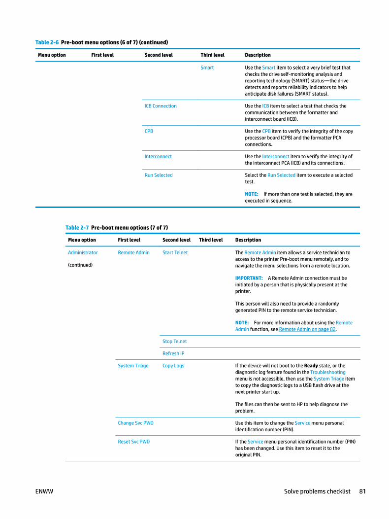
Table 2-6 Pre-boot menu options (6 of 7) (continued)
Menu option First level Second level Third level Description
Smart Use the Smart item to select a very brief test that checks the drive self-monitoring analysis and reporting technology (SMART) status—the drive detects and reports reliability indicators to help anticipate disk failures (SMART status).
ICB Connection Use the ICB item to select a test that checks the communication between the formatter and interconnect board (ICB).
CPB Use the CPB item to verify the integrity of the copy processor board (CPB) and the formatter PCA connections.
Interconnect Use the Interconnect item to verify the integrity of the interconnect PCA (ICB) and its connections.
Run Selected Select the Run Selected item to execute a selected test.
NOTE: If more than one test is selected, they are executed in sequence.
Table 2-7 Pre-boot menu options (7 of 7)
Menu option First level Second level Third level Description
Administrator
(continued)
Remote Admin Start Telnet The Remote Admin item allows a service technician to access to the printer Pre-boot menu remotely, and to navigate the menu selections from a remote location.
IMPORTANT: A Remote Admin connection must be initiated by a person that is physically present at the printer.
This person will also need to provide a randomly generated PIN to the remote service technician.
NOTE: For more information about using the Remote Admin function, see Remote Admin on page 82.
Stop Telnet
Refresh IP
System Triage Copy Logs If the device will not boot to the Ready state, or the diagnostic log feature found in the Troubleshooting menu is not accessible, then use the System Triage item to copy the diagnostic logs to a USB flash drive at the next printer start up.
The files can then be sent to HP to help diagnose the problem.
Change Svc PWD Use this item to change the Service menu personal identification number (PIN).
Reset Svc PWD If the Service menu personal identification number (PIN) has been changed. Use this item to reset it to the original PIN.
ENWW Solve problems checklist 81
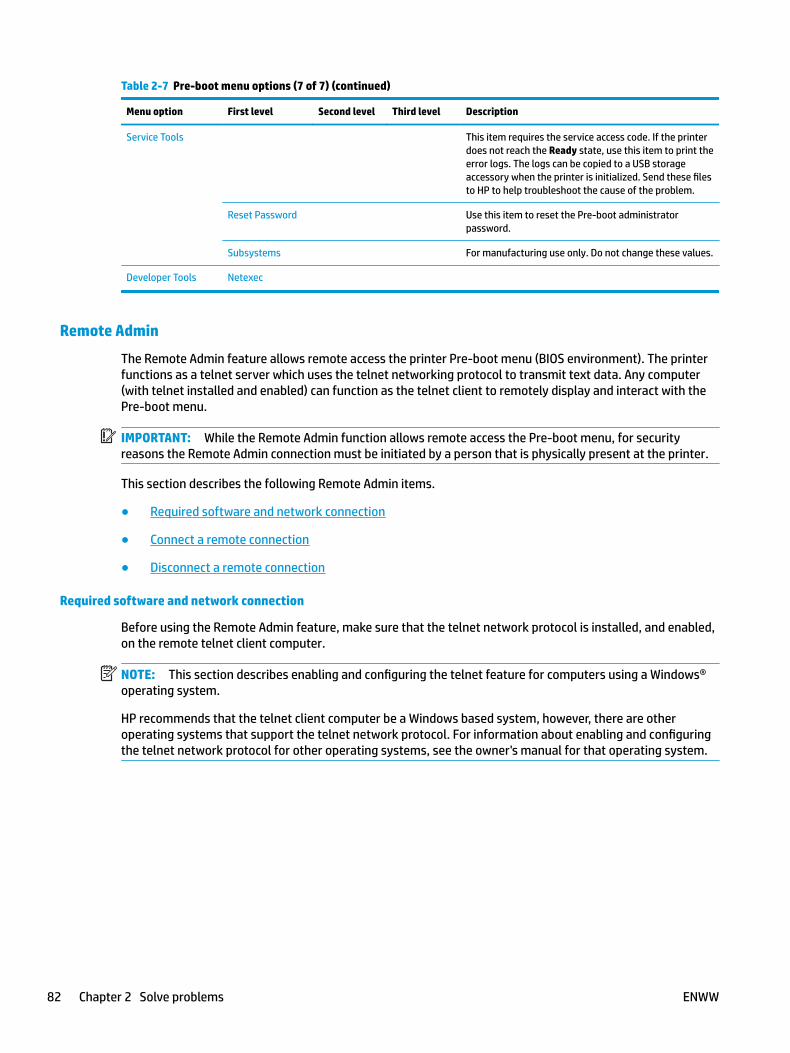
Table 2-7 Pre-boot menu options (7 of 7) (continued)
Menu option First level Second level Third level Description
Service Tools This item requires the service access code. If the printer does not reach the Ready state, use this item to print the error logs. The logs can be copied to a USB storage accessory when the printer is initialized. Send these files to HP to help troubleshoot the cause of the problem.
Reset Password Use this item to reset the Pre-boot administrator password.
Subsystems For manufacturing use only. Do not change these values.
Developer Tools Netexec
Remote Admin
The Remote Admin feature allows remote access the printer Pre-boot menu (BIOS environment). The printer functions as a telnet server which uses the telnet networking protocol to transmit text data. Any computer (with telnet installed and enabled) can function as the telnet client to remotely display and interact with the Pre-boot menu.
IMPORTANT: While the Remote Admin function allows remote access the Pre-boot menu, for security reasons the Remote Admin connection must be initiated by a person that is physically present at the printer.
This section describes the following Remote Admin items.
● Required software and network connection
● Connect a remote connection
● Disconnect a remote connection
Required software and network connection
Before using the Remote Admin feature, make sure that the telnet network protocol is installed, and enabled, on the remote telnet client computer.
NOTE: This section describes enabling and configuring the telnet feature for computers using a Windows® operating system.
HP recommends that the telnet client computer be a Windows based system, however, there are other operating systems that support the telnet network protocol. For information about enabling and configuring the telnet network protocol for other operating systems, see the owner's manual for that operating system.
82 Chapter 2 Solve problems ENWW
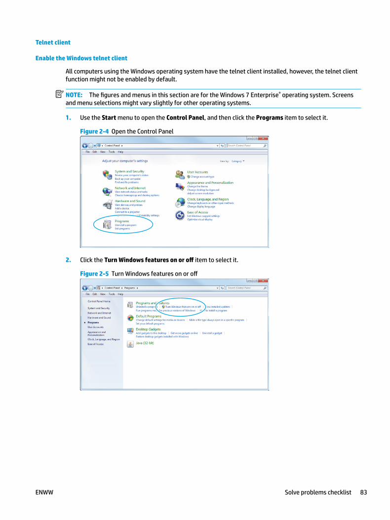
Telnet client
Enable the Windows telnet client
All computers using the Windows operating system have the telnet client installed, however, the telnet client function might not be enabled by default.
NOTE: The figures and menus in this section are for the Windows 7 Enterprise® operating system. Screens and menu selections might vary slightly for other operating systems.
1. Use the Start menu to open the Control Panel, and then click the Programs item to select it.
Figure 2-4 Open the Control Panel
2. Click the Turn Windows features on or off item to select it.
Figure 2-5 Turn Windows features on or off
ENWW Solve problems checklist 83
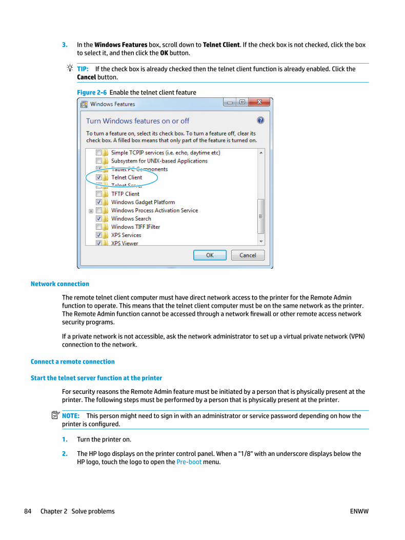
3. In the Windows Features box, scroll down to Telnet Client. If the check box is not checked, click the box to select it, and then click the OK button.
TIP: If the check box is already checked then the telnet client function is already enabled. Click the Cancel button.
Figure 2-6 Enable the telnet client feature
Network connection
The remote telnet client computer must have direct network access to the printer for the Remote Admin function to operate. This means that the telnet client computer must be on the same network as the printer. The Remote Admin function cannot be accessed through a network firewall or other remote access network security programs.
If a private network is not accessible, ask the network administrator to set up a virtual private network (VPN) connection to the network.
Connect a remote connection
Start the telnet server function at the printer
For security reasons the Remote Admin feature must be initiated by a person that is physically present at the printer. The following steps must be performed by a person that is physically present at the printer.
NOTE: This person might need to sign in with an administrator or service password depending on how the printer is configured.
1. Turn the printer on.
2. The HP logo displays on the printer control panel. When a "1/8" with an underscore displays below the HP logo, touch the logo to open the Pre-boot menu.
84 Chapter 2 Solve problems ENWW

3. Use the arrow buttons on the touchscreen to scroll down and highlight the +3:Administrator item, and then touch the OK button to select it.
Figure 2-7 Select the +3:Administrator item
4. Use the arrow buttons on the touchscreen to scroll down and highlight the +A:Remote Admin item, and then touch the OK button to select it.
Figure 2-8 Select the +A:Remote Admin item
5. Use the arrow buttons on the touchscreen to scroll down and highlight the 1:Start Telnet item, and then touch the OK button to select it.
Figure 2-9 Select the 1:Start Telnet item
6. Do one of the following
● If a connecting message displays briefly, go to step 7.
Figure 2-10 Telnet connecting message
● If an error message displays, use the steps below to identify the problem.
ENWW Solve problems checklist 85

Figure 2-11 Telnet error message
a. The printer network cable is not correctly connected.
b. The BIOS LAN settings are incorrect.
● The printer should be configured to use a static IP address, but is configured to use DHCP instead.
● The printer is configured to use a static IP address, but the IP address is incorrect.
c. The printer is correctly configured to use DHCP, but the DHCP server is not turned on or is malfunctioning.
7. When the printer telnet server function is initialized, the following screen appears. Use the information on this screen to connect the remote telnet client computer to the printer.
NOTE: The printer is now ready to receive remote telnet client commands.
● IP: The static or dynamically allocated IP address for the printer.
● Port: The standard telnet port (23).
● Pin: A randomly generated 4-digit personal identification number (PIN).
Figure 2-12 Telnet server function initialized
Start the telnet client function at the remote computer
The following steps establish a Remote Admin connection from a remote computer to the printer.
1. From the Start menu click Run to open a dialog box, type cmd in the Open field, and then click the OK button to open a Windows command window.
86 Chapter 2 Solve problems ENWW

Figure 2-13 Open a command window
1
2
2. From any displayed directory, type telnet at the prompt, and then press the Enter key.
Figure 2-14 Start a telnet session
3. Type o <IP ADDRESS> at the telnet prompt, and then press the Enter key.
NOTE: For <IP ADDRESS>, substitute the IP address that was displayed in step 7 in Start the telnet server function at the printer on page 84.
TIP: If the telnet connection fails to establish a connection, the printer is probably behind a firewall or on a different network that the remote telnet client computer. See Network connection on page 84.
Figure 2-15 Establish a telnet connection
ENWW Solve problems checklist 87

4. Type the PIN that was displayed in step 7 in Start the telnet server function at the printer on page 84 at the prompt, and then press the Enter key.
IMPORTANT: Make sure to type the PIN correctly. After five incorrect PIN entries, the printer terminates the Remote Admin connection. The Remote Admin feature must be re-initiated at the printer. See Start the telnet server function at the printer on page 84.
Figure 2-16 Enter the PIN
5. The following screen displays when the correct PIN is entered and the Remote Admin connection is successful. For information about the Pre-boot menu and options, see Pre-boot menu options on page 73.
NOTE: Because a Remote Admin connection is an unsecure telnet network protocol connection, the following Pre-boot menu items are disabled for the remote telnet client computer.
● The +3:Administrator menu 4:Change Password item.
● The +3:Administrator menu 5:Clear Password item.
● The +3:Administrator menu 6:Disk Manage item.
Figure 2-17 Remote Admin window
Disconnect a remote connection
The Remote Admin connection can be terminated from the printer control panel or the remote telnet client computer.
NOTE: The following procedure describes terminating a Remote Admin connection from the remote telnet client computer.
88 Chapter 2 Solve problems ENWW
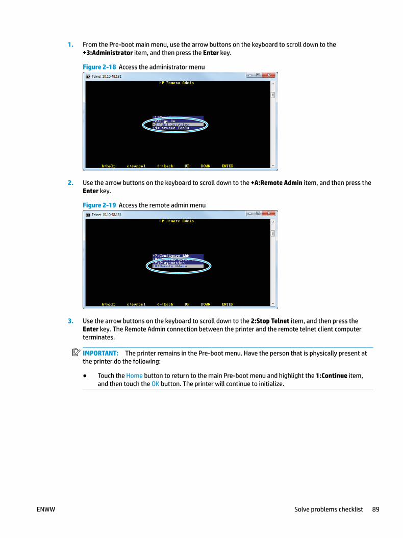
1. From the Pre-boot main menu, use the arrow buttons on the keyboard to scroll down to the +3:Administrator item, and then press the Enter key.
Figure 2-18 Access the administrator menu
2. Use the arrow buttons on the keyboard to scroll down to the +A:Remote Admin item, and then press the Enter key.
Figure 2-19 Access the remote admin menu
3. Use the arrow buttons on the keyboard to scroll down to the 2:Stop Telnet item, and then press the Enter key. The Remote Admin connection between the printer and the remote telnet client computer terminates.
IMPORTANT: The printer remains in the Pre-boot menu. Have the person that is physically present at the printer do the following:
● Touch the Home button to return to the main Pre-boot menu and highlight the 1:Continue item, and then touch the OK button. The printer will continue to initialize.
ENWW Solve problems checklist 89

Figure 2-20 Terminate the telnet connection
90 Chapter 2 Solve problems ENWW

Troubleshooting process● Determine the problem source
● Power subsystem
● Control panel checks
Determine the problem sourceWhen the printer malfunctions or encounters an unexpected situation, the printer control panel alerts the user to the situation. This section contains a pre-troubleshooting checklist to filter out many possible causes of the problem. Use the troubleshooting flowchart to help diagnose the root cause of the problem. The remainder of this chapter provides steps for correcting problems.
● Use the troubleshooting flowchart to pinpoint the root cause of hardware malfunctions. The flowchart provides guides to the section of this chapter that contain steps to correct the malfunction.
Before beginning any troubleshooting procedure, check the following issues:
● Are supply items within their rated life?
● Does the configuration page reveal any configuration errors?
NOTE: The customer is responsible for checking supplies and for using supplies that are in good condition.
Troubleshooting flowchart
This flowchart highlights the general processes to follow to quickly isolate and solve printer hardware problems.
Each row depicts a major troubleshooting step. Follow a “yes” answer to a question to proceed to the next major step. A “no” answer indicates that more testing is needed. Go to the appropriate section in this chapter, and follow the instructions there. After completing the instructions, go to the next major step in this troubleshooting flowchart.
Table 2-8 Troubleshooting flowchart
1
Power on
Is the printer on and does a readable message display?
Follow the power-on troubleshooting checks. See Power subsystem on page 92.
After the control panel display is functional, see step 2.Yes No
2
Control panel messages
Does the message Ready display on the control panel?
After the errors have been corrected, go to step 3.
Yes No
3
Event log
Open the Troubleshooting menu and print an event log to see the history of errors with this printer.
Does the event log print?
If the event log does not print, check for error messages.
If paper jams inside the printer, see the jams section of the printer service manual.
If error messages display on the control panel when trying to print an event log, see the control panel message section of the printer troubleshooting service manual.
After successfully printing and evaluating the event log, see step 4.
Yes No
ENWW Troubleshooting process 91

Table 2-8 Troubleshooting flowchart (continued)
4
Information pages
Open the Reports menu and print the configuration pages to verify that all the accessories are installed.
Are all the accessories installed?
If accessories that are installed are not listed on the configuration page, remove the accessory and reinstall it.
After evaluating the configuration pages, see step 5.
Yes No
5
Print quality
Does the print quality meet the customer's requirements?
Compare the images with the sample defects in the image defect tables. See the images defects table in the printer repair service manual.
After the print quality is acceptable, see step 6.Yes No
6
Interface
Can the customer print successfully from the host computer?
Verify that all I/O cables are connected correctly and that a valid IP address is listed on the HP Jetdirect configuration page.
If error messages display on the control panel when trying to print an event log, see the control-panel message section of the printer troubleshooting service manual.
When the customer can print from the host computer, this is the end of the troubleshooting process.
Yes. This is the end of the troubleshooting process.
No
Power subsystem
Power-on checks
The basic printer functions should start up when the printer is connected into an electrical outlet and the power switch is pushed to the on position. If the printer does not start, use the information in this section to isolate and solve the problem.
If the control panel display remains blank, random patterns display, or asterisks remain on the control panel display, perform power-on checks to find the cause of the problem.
NOTE: For touchscreen control panel models, also try the control panel checks in the printer troubleshooting manual.
Power-on troubleshooting overview
During normal operation, a cooling fan begins to spin briefly after the printer power is turned on. Place a hand over the vents in the rear cover, near the formatter. When the fan is correctly operating, air passing out of the printer is felt. Lean close to the printer to hear the fan operating. If the fan is operating, the dc side of the power supply is functioning.
After the fan is operating, the main motor turns on (unless the top cover is open, a jam condition is sensed, or the paper-path sensors are damaged). Visually and audibly determine that the main motor is turned on.
If the fan and main motor are operating correctly, the next troubleshooting step is to isolate print engine, formatter, and control panel problems. Perform an engine test. If the formatter is damaged, it might interfere with the engine test. If the engine-test page does not print, try removing the formatter, and then performing the engine test again. If the engine test is then successful, the problem is almost certainly with the formatter, the control panel, or the cable that connects them.
92 Chapter 2 Solve problems ENWW
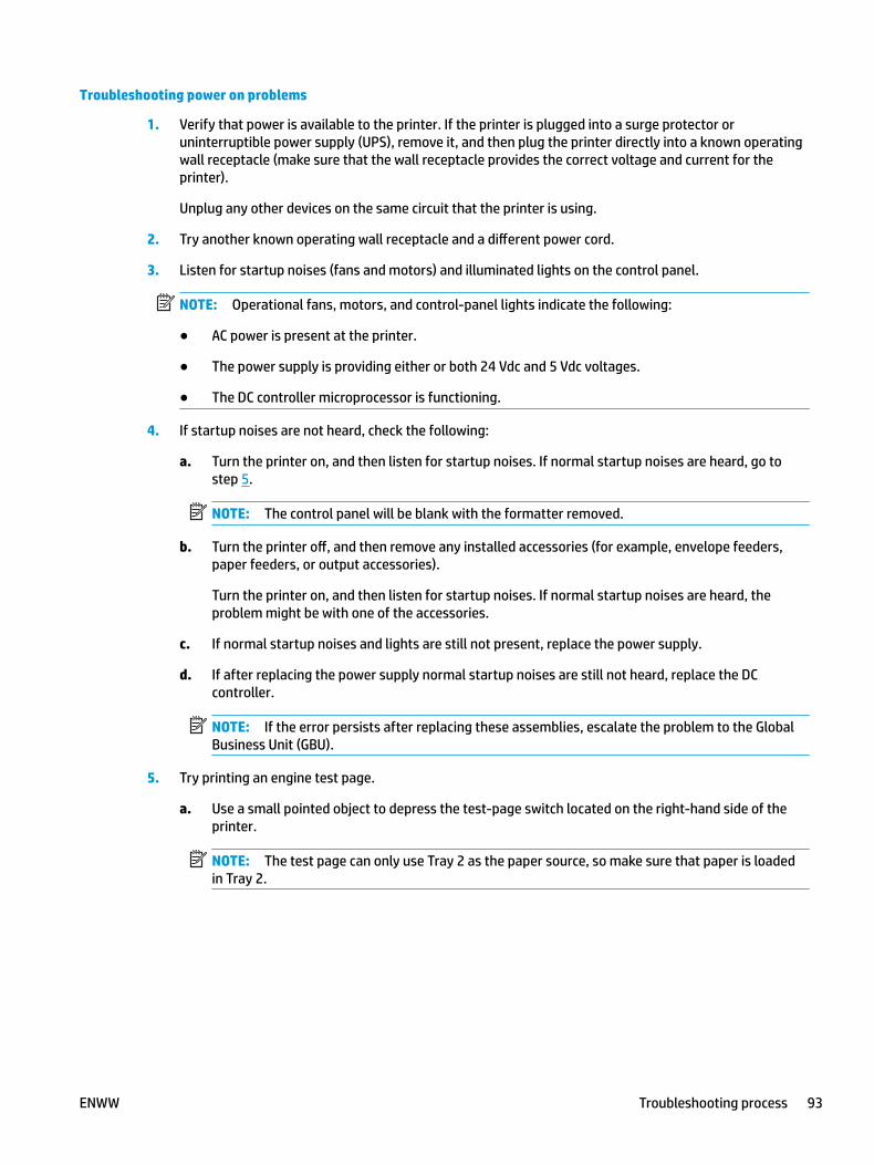
Troubleshooting power on problems
1. Verify that power is available to the printer. If the printer is plugged into a surge protector or uninterruptible power supply (UPS), remove it, and then plug the printer directly into a known operating wall receptacle (make sure that the wall receptacle provides the correct voltage and current for the printer).
Unplug any other devices on the same circuit that the printer is using.
2. Try another known operating wall receptacle and a different power cord.
3. Listen for startup noises (fans and motors) and illuminated lights on the control panel.
NOTE: Operational fans, motors, and control-panel lights indicate the following:
● AC power is present at the printer.
● The power supply is providing either or both 24 Vdc and 5 Vdc voltages.
● The DC controller microprocessor is functioning.
4. If startup noises are not heard, check the following:
a. Turn the printer on, and then listen for startup noises. If normal startup noises are heard, go to step 5.
NOTE: The control panel will be blank with the formatter removed.
b. Turn the printer off, and then remove any installed accessories (for example, envelope feeders, paper feeders, or output accessories).
Turn the printer on, and then listen for startup noises. If normal startup noises are heard, the problem might be with one of the accessories.
c. If normal startup noises and lights are still not present, replace the power supply.
d. If after replacing the power supply normal startup noises are still not heard, replace the DC controller.
NOTE: If the error persists after replacing these assemblies, escalate the problem to the Global Business Unit (GBU).
5. Try printing an engine test page.
a. Use a small pointed object to depress the test-page switch located on the right-hand side of the printer.
NOTE: The test page can only use Tray 2 as the paper source, so make sure that paper is loaded in Tray 2.
ENWW Troubleshooting process 93
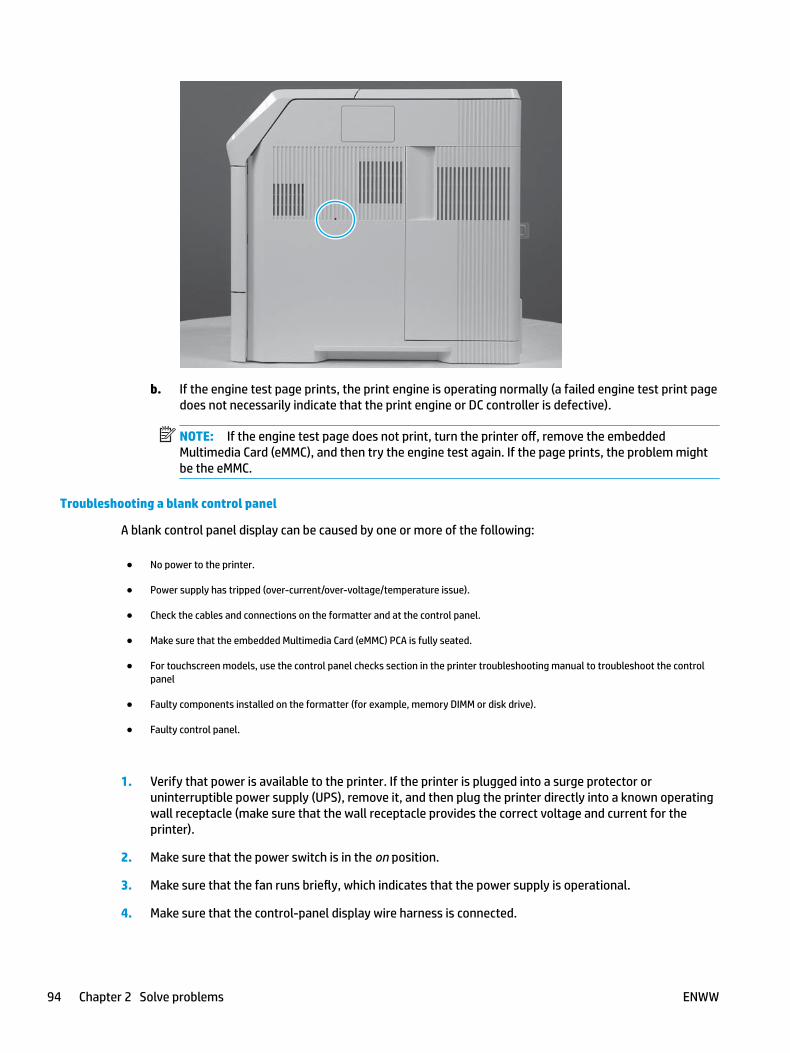
b. If the engine test page prints, the print engine is operating normally (a failed engine test print page does not necessarily indicate that the print engine or DC controller is defective).
NOTE: If the engine test page does not print, turn the printer off, remove the embedded Multimedia Card (eMMC), and then try the engine test again. If the page prints, the problem might be the eMMC.
Troubleshooting a blank control panel
A blank control panel display can be caused by one or more of the following:
● No power to the printer.
● Power supply has tripped (over-current/over-voltage/temperature issue).
● Check the cables and connections on the formatter and at the control panel.
● Make sure that the embedded Multimedia Card (eMMC) PCA is fully seated.
● For touchscreen models, use the control panel checks section in the printer troubleshooting manual to troubleshoot the control panel
● Faulty components installed on the formatter (for example, memory DIMM or disk drive).
● Faulty control panel.
1. Verify that power is available to the printer. If the printer is plugged into a surge protector or uninterruptible power supply (UPS), remove it, and then plug the printer directly into a known operating wall receptacle (make sure that the wall receptacle provides the correct voltage and current for the printer).
2. Make sure that the power switch is in the on position.
3. Make sure that the fan runs briefly, which indicates that the power supply is operational.
4. Make sure that the control-panel display wire harness is connected.
94 Chapter 2 Solve problems ENWW
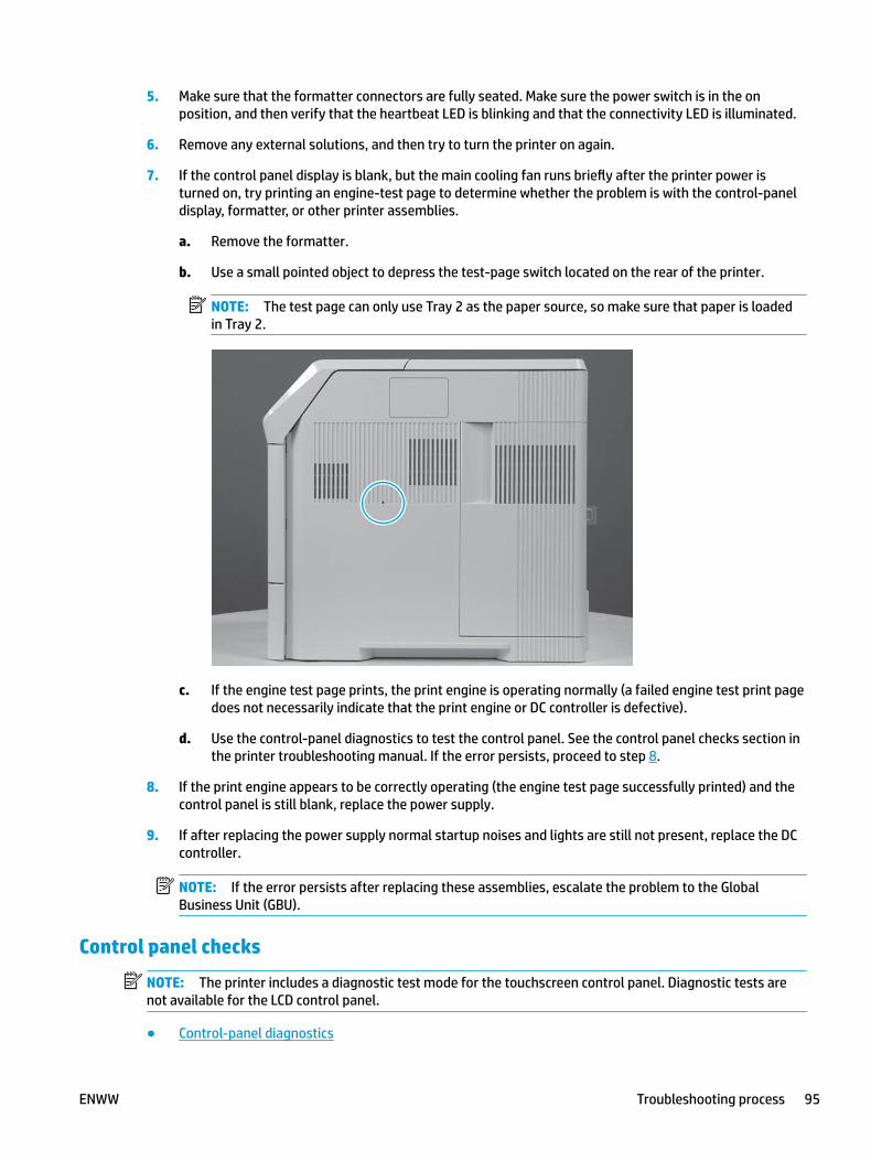
5. Make sure that the formatter connectors are fully seated. Make sure the power switch is in the on position, and then verify that the heartbeat LED is blinking and that the connectivity LED is illuminated.
6. Remove any external solutions, and then try to turn the printer on again.
7. If the control panel display is blank, but the main cooling fan runs briefly after the printer power is turned on, try printing an engine-test page to determine whether the problem is with the control-panel display, formatter, or other printer assemblies.
a. Remove the formatter.
b. Use a small pointed object to depress the test-page switch located on the rear of the printer.
NOTE: The test page can only use Tray 2 as the paper source, so make sure that paper is loaded in Tray 2.
c. If the engine test page prints, the print engine is operating normally (a failed engine test print page does not necessarily indicate that the print engine or DC controller is defective).
d. Use the control-panel diagnostics to test the control panel. See the control panel checks section in the printer troubleshooting manual. If the error persists, proceed to step 8.
8. If the print engine appears to be correctly operating (the engine test page successfully printed) and the control panel is still blank, replace the power supply.
9. If after replacing the power supply normal startup noises and lights are still not present, replace the DC controller.
NOTE: If the error persists after replacing these assemblies, escalate the problem to the Global Business Unit (GBU).
Control panel checks
NOTE: The printer includes a diagnostic test mode for the touchscreen control panel. Diagnostic tests are not available for the LCD control panel.
● Control-panel diagnostics
ENWW Troubleshooting process 95
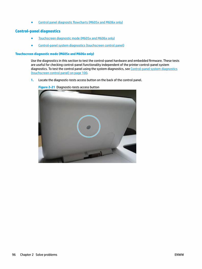
● Control panel diagnostic flowcharts (M605x and M606x only)
Control-panel diagnostics
● Touchscreen diagnostic mode (M605x and M606x only)
● Control-panel system diagnostics (touchscreen control panel)
Touchscreen diagnostic mode (M605x and M606x only)
Use the diagnostics in this section to test the control-panel hardware and embedded firmware. These tests are useful for checking control-panel functionality independent of the printer control-panel system diagnostics. To test the control panel using the system diagnostics, see Control-panel system diagnostics (touchscreen control panel) on page 100.
1. Locate the diagnostic-tests access button on the back of the control panel.
Figure 2-21 Diagnostic-tests access button
96 Chapter 2 Solve problems ENWW
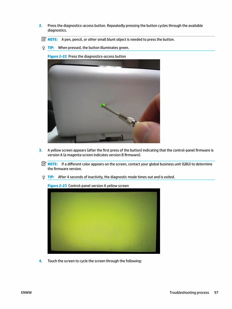
2. Press the diagnostics-access button. Repeatedly pressing the button cycles through the available diagnostics.
NOTE: A pen, pencil, or other small blunt object is needed to press the button.
TIP: When pressed, the button illuminates green.
Figure 2-22 Press the diagnostics-access button
3. A yellow screen appears (after the first press of the button) indicating that the control-panel firmware is version A (a magenta screen indicates version B firmware).
NOTE: If a different color appears on the screen, contact your global business unit (GBU) to determine the firmware version.
TIP: After 4 seconds of inactivity, the diagnostic mode times out and is exited.
Figure 2-23 Control-panel version A yellow screen
4. Touch the screen to cycle the screen through the following:
ENWW Troubleshooting process 97

● A red screen, a green screen, and a blue screen.
● Five brightness levels of a white screen.
● A final black screen.
TIP: When the final black screen displays, press the Home button to cycle through the diagnostic screens and test its functionality.
Figure 2-24 Touch the screen to advance colored screens
98 Chapter 2 Solve problems ENWW

5. Pressing the diagnostic-tests button with the black screen displayed, exits the diagnostic mode.
Figure 2-25 Exit the diagnostic mode
ENWW Troubleshooting process 99

Control-panel system diagnostics (touchscreen control panel)
Use the diagnostics in this section to test the control-panel hardware and display using the printer firmware system diagnostics.
● Open the control-panel system diagnostic tests
● Screen test
● Touch test
● SoftKey test
● Backlight test
● Sound test
● Keyboard test
● Version
Open the control-panel system diagnostic tests
Open the control-panel system diagnostic tests from a touchscreen control panel
1. Touch the HP logo in the middle of the control-panel display when you see the 1/8 under the logo.
Figure 2-26 Open the Pre-boot menu
1 2
100 Chapter 2 Solve problems ENWW
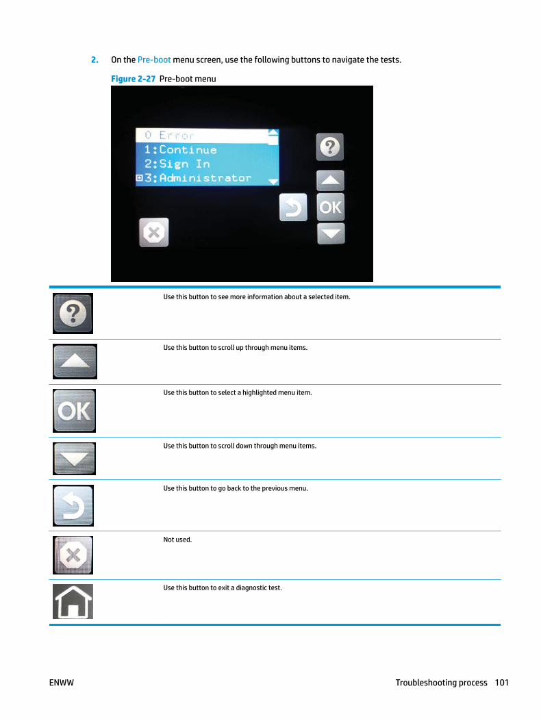
2. On the Pre-boot menu screen, use the following buttons to navigate the tests.
Figure 2-27 Pre-boot menu
Use this button to see more information about a selected item.
Use this button to scroll up through menu items.
Use this button to select a highlighted menu item.
Use this button to scroll down through menu items.
Use this button to go back to the previous menu.
Not used.
Use this button to exit a diagnostic test.
ENWW Troubleshooting process 101
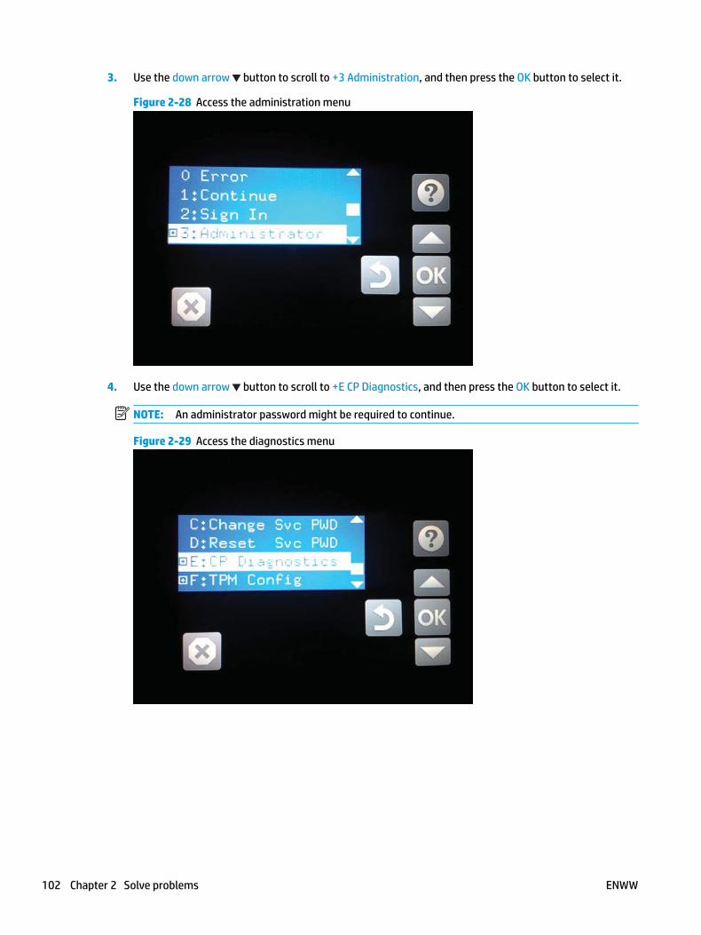
3. Use the down arrow button to scroll to +3 Administration, and then press the OK button to select it.
Figure 2-28 Access the administration menu
4. Use the down arrow button to scroll to +E CP Diagnostics, and then press the OK button to select it.
NOTE: An administrator password might be required to continue.
Figure 2-29 Access the diagnostics menu
102 Chapter 2 Solve problems ENWW

Screen test
1. Open the control-panel system diagnostic tests. See Open the control-panel system diagnostic tests on page 100.
2. With 1 Screen Test highlighted, press the OK button to select it.
Figure 2-30 Open the screen test
3. The blue vertical gradient screen appears.
Figure 2-31 Blue vertical gradient screen
4. Touch the touchscreen to scroll though the remaining touchscreen test screens.
NOTE: Touch the Home button to exit the test.
ENWW Troubleshooting process 103
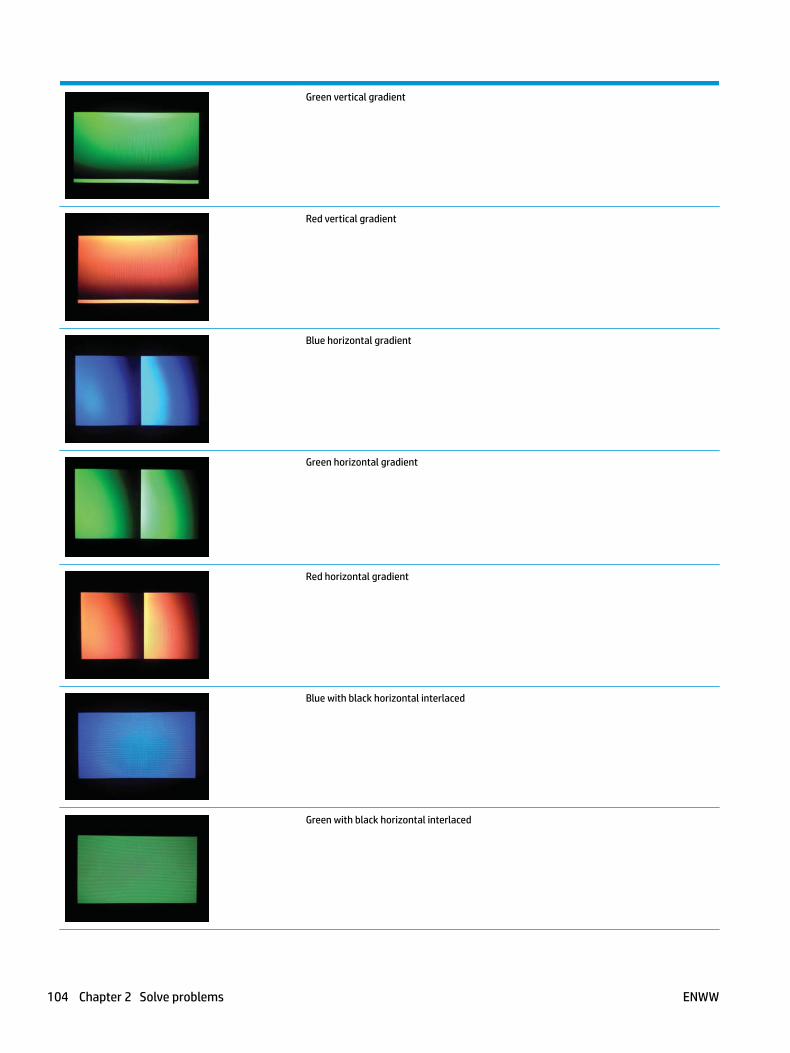
Green vertical gradient
Red vertical gradient
Blue horizontal gradient
Green horizontal gradient
Red horizontal gradient
Blue with black horizontal interlaced
Green with black horizontal interlaced
104 Chapter 2 Solve problems ENWW

Red with black horizontal interlaced
Blue with black vertical interlaced
Green with black vertical interlaced
Red with black vertical interlaced
Black with white center
White with black center
Checkerboard
ENWW Troubleshooting process 105

Multicolor stripes
Blue green grid meshing
106 Chapter 2 Solve problems ENWW
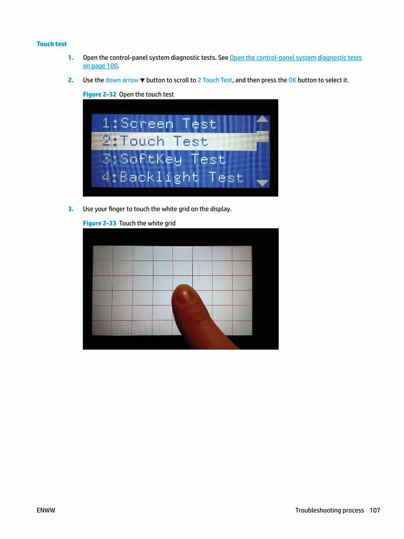
Touch test
1. Open the control-panel system diagnostic tests. See Open the control-panel system diagnostic tests on page 100.
2. Use the down arrow button to scroll to 2 Touch Test, and then press the OK button to select it.
Figure 2-32 Open the touch test
3. Use your finger to touch the white grid on the display.
Figure 2-33 Touch the white grid
ENWW Troubleshooting process 107
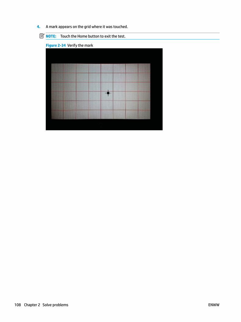
4. A mark appears on the grid where it was touched.
NOTE: Touch the Home button to exit the test.
Figure 2-34 Verify the mark
108 Chapter 2 Solve problems ENWW
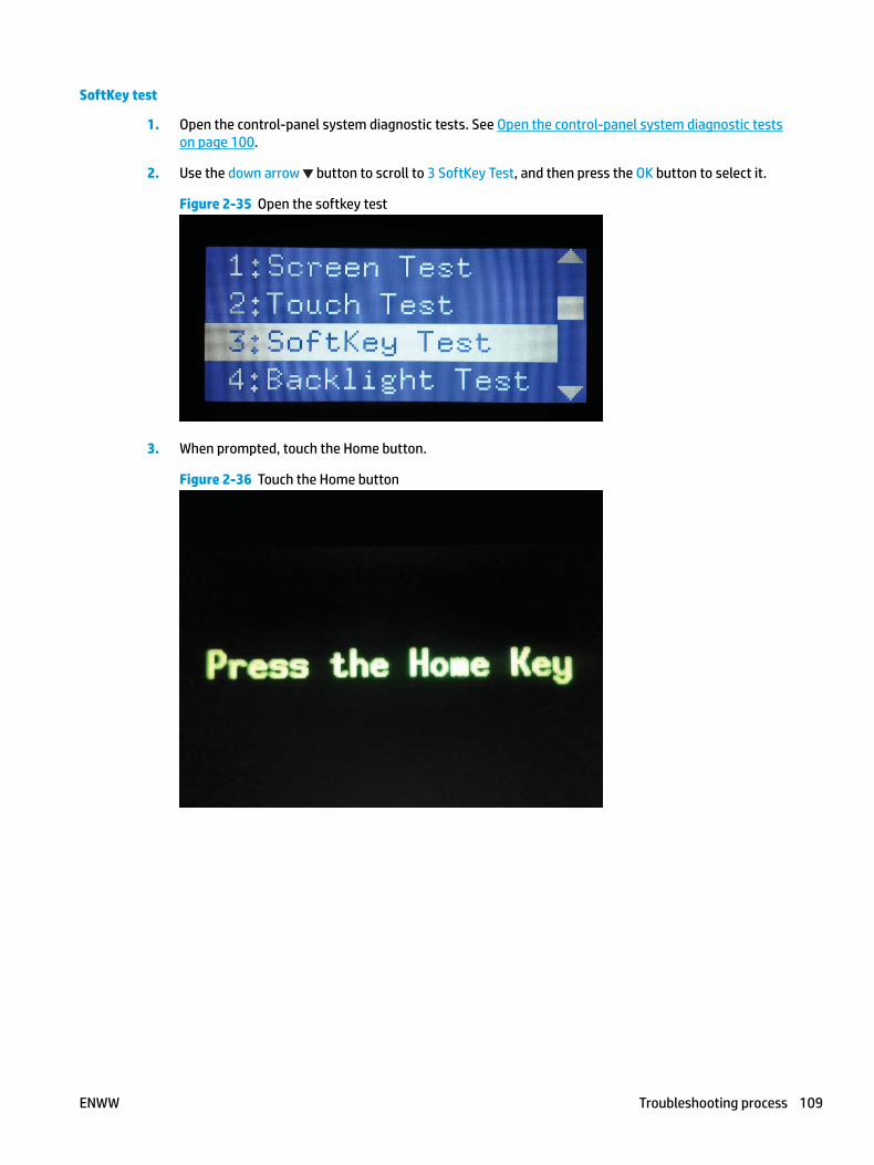
SoftKey test
1. Open the control-panel system diagnostic tests. See Open the control-panel system diagnostic tests on page 100.
2. Use the down arrow button to scroll to 3 SoftKey Test, and then press the OK button to select it.
Figure 2-35 Open the softkey test
3. When prompted, touch the Home button.
Figure 2-36 Touch the Home button
ENWW Troubleshooting process 109
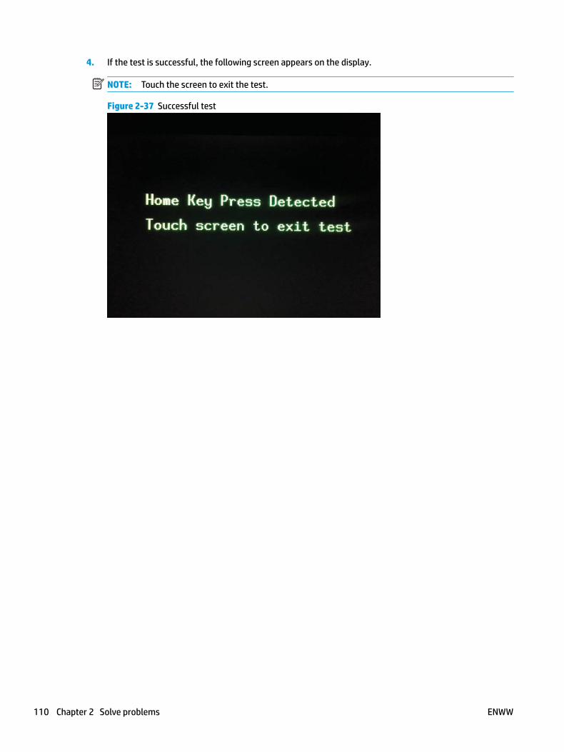
4. If the test is successful, the following screen appears on the display.
NOTE: Touch the screen to exit the test.
Figure 2-37 Successful test
110 Chapter 2 Solve problems ENWW
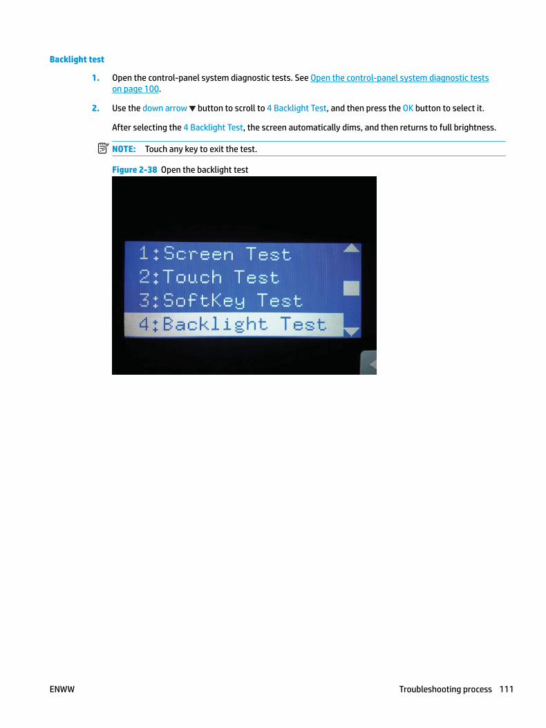
Backlight test
1. Open the control-panel system diagnostic tests. See Open the control-panel system diagnostic tests on page 100.
2. Use the down arrow button to scroll to 4 Backlight Test, and then press the OK button to select it.
After selecting the 4 Backlight Test, the screen automatically dims, and then returns to full brightness.
NOTE: Touch any key to exit the test.
Figure 2-38 Open the backlight test
ENWW Troubleshooting process 111

Sound test
1. Open the control-panel system diagnostic tests. See Open the control-panel system diagnostic tests on page 100.
2. Use the down arrow button to scroll to 5 Sound Test, and then press the OK button to select it.
After selecting the 5 Sound Test, the printer emits a series of audible tones.
NOTE: Touch any key to exit the test.
Figure 2-39 Open the sound test
112 Chapter 2 Solve problems ENWW
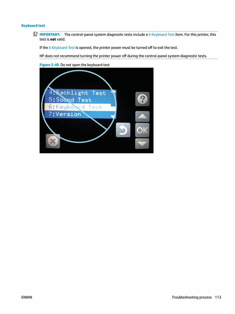
Keyboard test
IMPORTANT: The control-panel system diagnostic tests include a 6 Keyboard Test item. For this printer, this test is not valid.
If the 6 Keyboard Test is opened, the printer power must be turned off to exit the test.
HP does not recommend turning the printer power off during the control-panel system diagnostic tests.
Figure 2-40 Do not open the keyboard test
ENWW Troubleshooting process 113
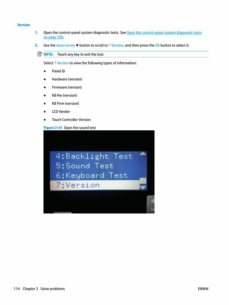
Version
1. Open the control-panel system diagnostic tests. See Open the control-panel system diagnostic tests on page 100.
2. Use the down arrow button to scroll to 7 Version, and then press the OK button to select it.
NOTE: Touch any key to exit the test.
Select 7 Version to view the following types of information:
● Panel ID
● Hardware (version)
● Firmware (version)
● KB Hw (version)
● KB Firm (version)
● LCD Vendor
● Touch Controller Version
Figure 2-41 Open the sound test
114 Chapter 2 Solve problems ENWW

Control panel diagnostic flowcharts (M605x and M606x only)
Use the flowcharts in this section to troubleshoot the following control panel problems.
● Touchscreen is blank, white, or dim (no image).
● Touchscreen is slow to respond or requires multiple presses to respond.
● Touchscreen has an unresponsive zone.
● No control panel sound.
● Home button is unresponsive.
● Hardware integration pocket (HIP) is not functioning (control panel functional).
ENWW Troubleshooting process 115
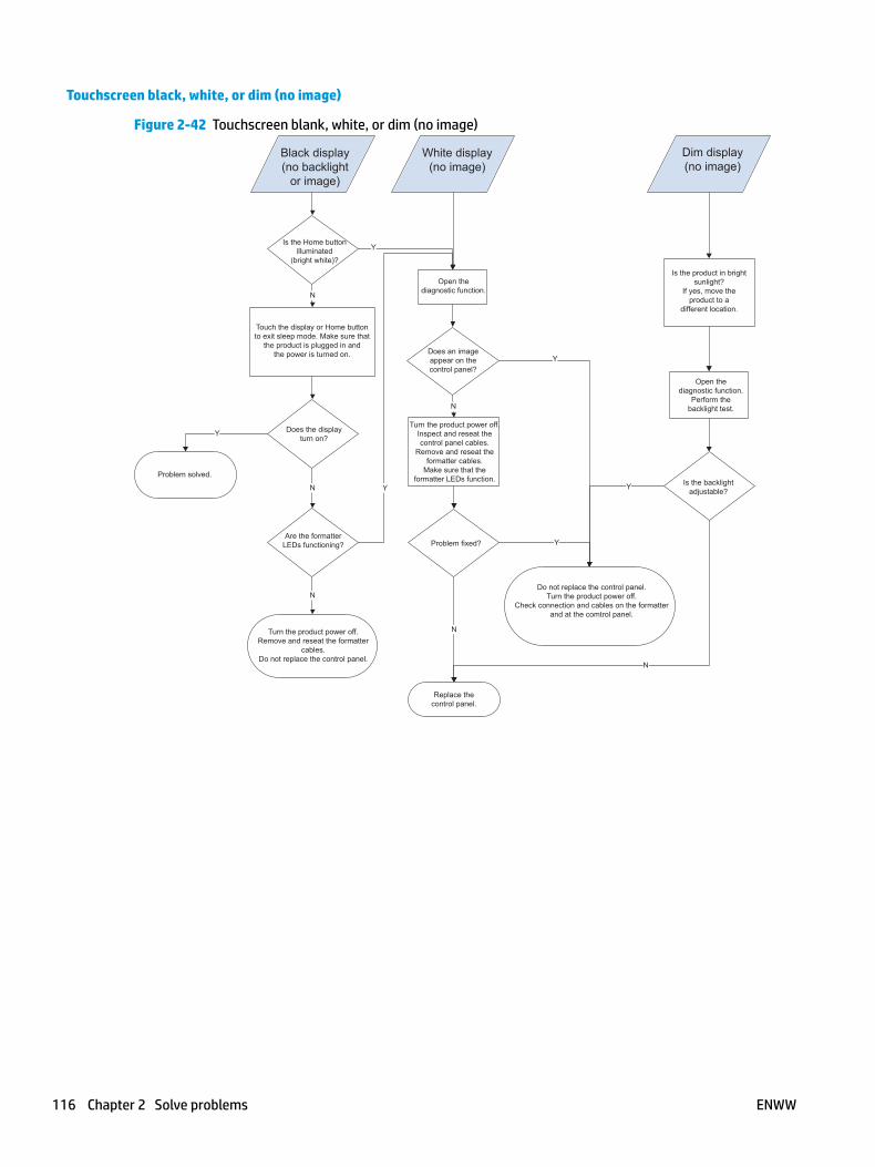
Touchscreen black, white, or dim (no image)
Figure 2-42 Touchscreen blank, white, or dim (no image)
N
N
Y
N
N
Y
Y
N
Y
Y
N
Y
Touch the display or Home buttonto exit sleep mode. Make sure that
the product is plugged in andthe power is turned on.
Black display(no backlight
or image)
White display(no image)
Dim display(no image)
Is the Home buttonilluminated
(bright white)?
Open thediagnostic function.
Does an imageappear on thecontrol panel?
Does the displayturn on?
Problem solved.
Are the formatterLEDs functioning?
Turn the product power off.Remove and reseat the formatter
cables.Do not replace the control panel.
Turn the product power off.Inspect and reseat thecontrol panel cables.
Remove and reseat theformatter cables.
Make sure that theformatter LEDs function.
Problem fixed?
Replace thecontrol panel.
Do not replace the control panel.Turn the product power off.
Check connection and cables on the formatterand at the comtrol panel.
Is the backlightadjustable?
Open thediagnostic function.
Perform thebacklight test.
Is the product in brightsunlight?
If yes, move theproduct to a
different location.
116 Chapter 2 Solve problems ENWW

Touchscreen is slow to respond or requires multiple presses to respond
TIP: Use the red-grid touch test to verify that all areas of the touchscreen are correctly functioning. See Touch test on page 107.
Figure 2-43 Touchscreen is slow to respond or requires multiple presses to respond
Touchscreen slow torespond or requires
multiple pressesto respond
Not a control-panel problem.Do not replace the control panel.
Troubleshoot firmware orsoftware application problems.
ENWW Troubleshooting process 117

Touchscreen has an unresponsive zone
Figure 2-44 Touchscreen has an unresponsive zone
N
Y
N
Y
N
Y
Touchscreenhas an
unresponsivezone
Is the area of thetouchscreen you are touching
greyed out (intentionallydeactivated)?
Does the previouslyinactive area respond
to a touch?
Open thediagnostic function.
Perform thetouch test.
Turn the productpower off,and thenon again.
Does the previouslyinactive area respond
to a touch?
Replace thecontrol panel.
Do not replace thecontrol panel.
118 Chapter 2 Solve problems ENWW

No control panel sound
Figure 2-45 No control panel sound
N
N
Y
Y
Control panelhas nosound
Turn the product power off.Remove the control panel.
Check the cables to the speaker.Reseat the cables to the speaker.
Turn the product power on.Can sounds be heard?
Can soundsbe heard?
Can soundsbe heard?
Replace the control panel.
Open the following menus:Administration
Display SettingsKey Press Sound
Select the following:On
Save
N
Do not replace thecontrol panel.
Open thediagnostic function.
Perform the sound test.
ENWW Troubleshooting process 119
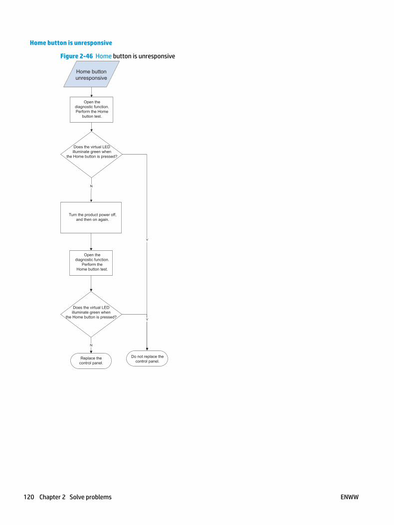
Home button is unresponsive
Figure 2-46 Home button is unresponsive
Y
N
N
Y
Home buttonunresponsive
Open thediagnostic function.Perform the Home
button test.
Does the virtual LEDilluminate green when
the Home button is pressed?
Turn the product power off,and then on again.
Open thediagnostic function.
Perform theHome button test.
Does the virtual LEDilluminate green when
the Home button is pressed?
Replace thecontrol panel.
Do not replace thecontrol panel.
120 Chapter 2 Solve problems ENWW

Hardware integration pocket (HIP) is not functioning (control panel functional)
Figure 2-47 Hardware integration pocket (HIP) is not functioning (control panel functional)
Hardware integrationpocket (HIP)not functional(control panel
functional)
Check that all installed hardware integrationpocket devices are within HP specifications.The control panel provides only 0.5 Amps to
the port. If an installed device attempts to drawmore power than is provided, the port is
automatically disabled. Troubleshoot third-party devices with the device manufacturer.
ENWW Troubleshooting process 121
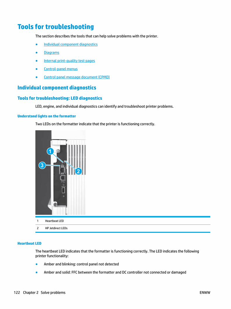
Tools for troubleshootingThe section describes the tools that can help solve problems with the printer.
● Individual component diagnostics
● Diagrams
● Internal print-quality test pages
● Control-panel menus
● Control panel message document (CPMD)
Individual component diagnostics
Tools for troubleshooting: LED diagnostics
LED, engine, and individual diagnostics can identify and troubleshoot printer problems.
Understand lights on the formatter
Two LEDs on the formatter indicate that the printer is functioning correctly.
1
23
1 Heartbeat LED
2 HP Jetdirect LEDs
Heartbeat LED
The heartbeat LED indicates that the formatter is functioning correctly. The LED indicates the following printer functionality:
● Amber and blinking: control panel not detected
● Amber and solid: FFC between the formatter and DC controller not connected or damaged
122 Chapter 2 Solve problems ENWW
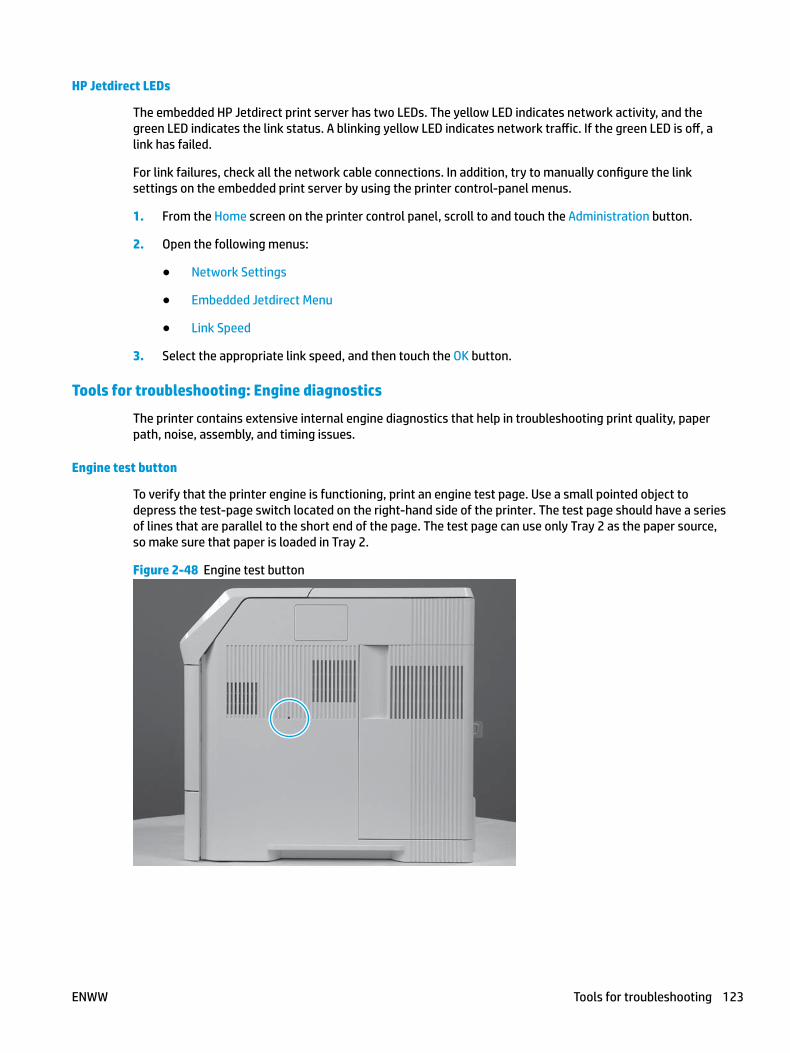
HP Jetdirect LEDs
The embedded HP Jetdirect print server has two LEDs. The yellow LED indicates network activity, and the green LED indicates the link status. A blinking yellow LED indicates network traffic. If the green LED is off, a link has failed.
For link failures, check all the network cable connections. In addition, try to manually configure the link settings on the embedded print server by using the printer control-panel menus.
1. From the Home screen on the printer control panel, scroll to and touch the Administration button.
2. Open the following menus:
● Network Settings
● Embedded Jetdirect Menu
● Link Speed
3. Select the appropriate link speed, and then touch the OK button.
Tools for troubleshooting: Engine diagnostics
The printer contains extensive internal engine diagnostics that help in troubleshooting print quality, paper path, noise, assembly, and timing issues.
Engine test button
To verify that the printer engine is functioning, print an engine test page. Use a small pointed object to depress the test-page switch located on the right-hand side of the printer. The test page should have a series of lines that are parallel to the short end of the page. The test page can use only Tray 2 as the paper source, so make sure that paper is loaded in Tray 2.
Figure 2-48 Engine test button
ENWW Tools for troubleshooting 123
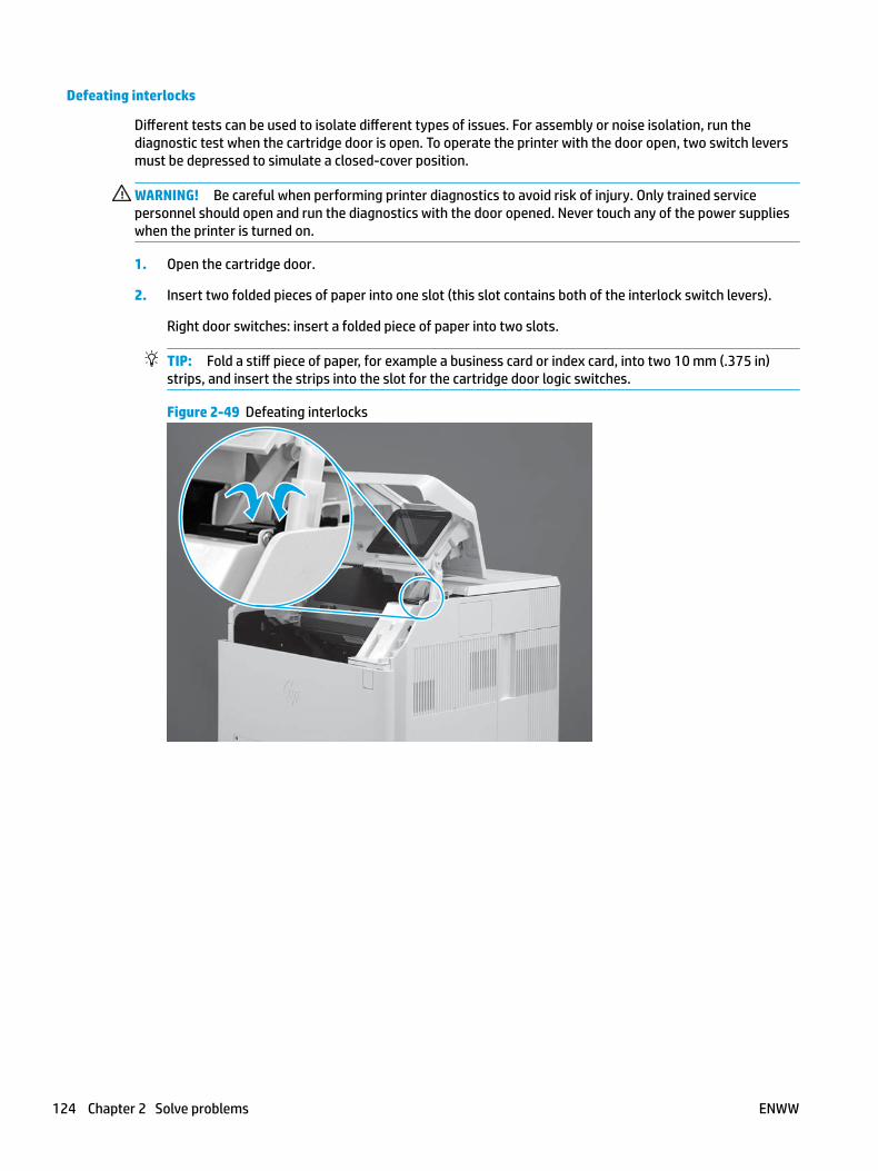
Defeating interlocks
Different tests can be used to isolate different types of issues. For assembly or noise isolation, run the diagnostic test when the cartridge door is open. To operate the printer with the door open, two switch levers must be depressed to simulate a closed-cover position.
WARNING! Be careful when performing printer diagnostics to avoid risk of injury. Only trained service personnel should open and run the diagnostics with the door opened. Never touch any of the power supplies when the printer is turned on.
1. Open the cartridge door.
2. Insert two folded pieces of paper into one slot (this slot contains both of the interlock switch levers).
Right door switches: insert a folded piece of paper into two slots.
TIP: Fold a stiff piece of paper, for example a business card or index card, into two 10 mm (.375 in) strips, and insert the strips into the slot for the cartridge door logic switches.
Figure 2-49 Defeating interlocks
124 Chapter 2 Solve problems ENWW

Disable cartridge check
Use this diagnostic test to print internal pages or send an external job to the printer when the toner cartridge is removed or exchanged. Supply errors are ignored while the printer is in this mode. When the printer is in this mode, access the troubleshooting menus and print internal pages (the print quality pages will be the most useful). This test can be used to isolate problems, such as noise, and to isolate print-quality problems that are related to the toner cartridge.
NOTE: Do not remove or exchange the toner cartridge until after beginning the disable cartridge check diagnostic.
Disable cartridge check from a touchscreen control panel
1. From the Home screen on the printer control panel, scroll to and touch the Administration button.
2. Open the following menus:
● Troubleshooting
● Diagnostic Tests
● Disable Cartridge Check
Disable cartridge check from a LCD control panel
1. From the Home screen on the printer control panel, use the down arrow button to scroll to Administration, and then press the OK button.
2. Use the down arrow button to scroll to Troubleshooting, and then press the OK button.
3. Use the down arrow button to scroll to Diagnostics, and then press the OK button.
4. Use the down arrow button to scroll to Disable Cartridge Check, and then press the OK button to select it.
ENWW Tools for troubleshooting 125
Tools for troubleshooting: Paper path and sensor diagnostic tests
Use these diagnostic tests to manually test the printer sensors, switches.
NOTE: The menu list of sensors and switches for the Paper path sensors test, Manual Sensor Test, and the Tray/Bin Manual Sensor Test varies depending on which optional accessories are installed.
The tables in this section describe the sensor tests available with an optional 1x500-sheet paper feeder, optional 1x1500-sheet high capacity input (HCI) feeder, and an optional 500-sheet stapler/stacker installed.
For trays other than Tray 1 or Tray 2, the tray number associated with a sensor or switch depends on the number and type of accessories installed.
Paper path test
This diagnostic test generates one or more test pages. Use these pages to isolate the cause of jams.
To isolate a problem, specify which input tray to use, specify whether to use the duplex path (duplex models only), and specify the number of copies to print. Multiple copies can be printed to help isolate intermittent problems. The following options become available after beginning the diagnostic feature:
● Print Test Page: Run the paper-path test from the default settings: Tray 2, no duplex, and one copy. To specify other settings, scroll down the menu, and select the setting, and then scroll back up and select Print Test Page to start the test.
● Source Tray: Select Tray 1, Tray 2, or the optional tray.
● Test Duplex Path: Enable or disable two-sided printing.
● Number of Copies: Set the numbers of copies to be printed; the choices are 1,10, 50, 100, or 500.
Access the paper path test from a touchscreen control panel
1. From the Home screen on the printer control panel, scroll to and touch the Administration button.
2. Open the following menus:
● Troubleshooting
● Diagnostic Tests
● Paper Path Test
3. Select the paper-path test options for the test.
Access the paper path test from a LCD control panel
1. From the Home screen on the printer control panel, use the down arrow button to scroll to Administration, and then press the OK button.
2. Use the down arrow button to scroll to Troubleshooting, and then press the OK button.
3. Use the down arrow button to scroll to Diagnostic Tests, and then press the OK button.
4. Use the down arrow button to scroll to Paper Path Test, and then press the OK button.
126 Chapter 2 Solve problems ENWW
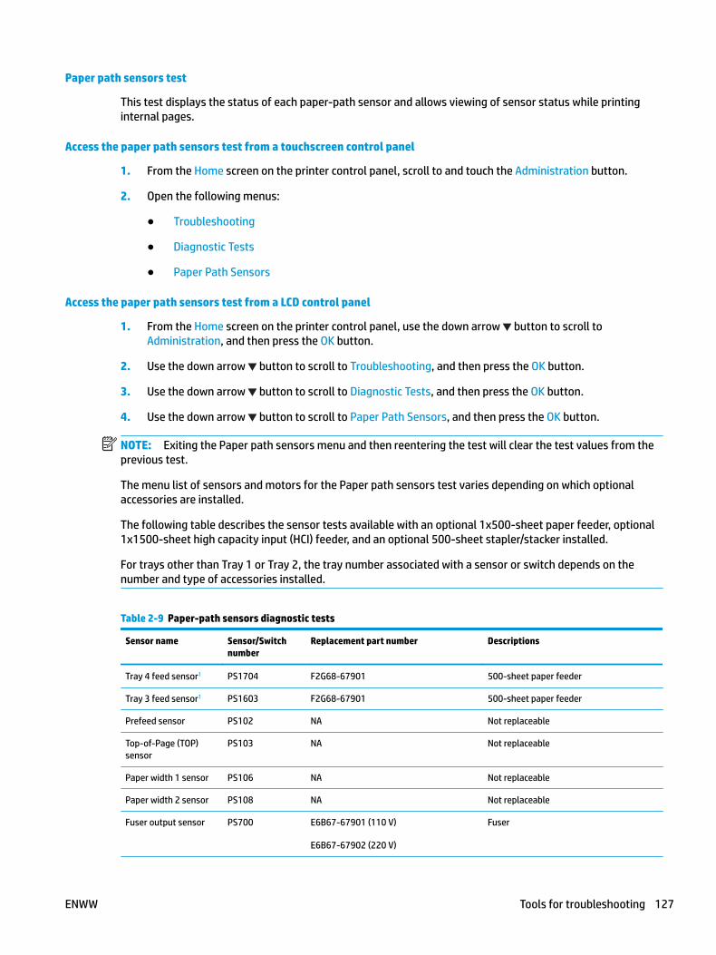
Paper path sensors test
This test displays the status of each paper-path sensor and allows viewing of sensor status while printing internal pages.
Access the paper path sensors test from a touchscreen control panel
1. From the Home screen on the printer control panel, scroll to and touch the Administration button.
2. Open the following menus:
● Troubleshooting
● Diagnostic Tests
● Paper Path Sensors
Access the paper path sensors test from a LCD control panel
1. From the Home screen on the printer control panel, use the down arrow button to scroll to Administration, and then press the OK button.
2. Use the down arrow button to scroll to Troubleshooting, and then press the OK button.
3. Use the down arrow button to scroll to Diagnostic Tests, and then press the OK button.
4. Use the down arrow button to scroll to Paper Path Sensors, and then press the OK button.
NOTE: Exiting the Paper path sensors menu and then reentering the test will clear the test values from the previous test.
The menu list of sensors and motors for the Paper path sensors test varies depending on which optional accessories are installed.
The following table describes the sensor tests available with an optional 1x500-sheet paper feeder, optional 1x1500-sheet high capacity input (HCI) feeder, and an optional 500-sheet stapler/stacker installed.
For trays other than Tray 1 or Tray 2, the tray number associated with a sensor or switch depends on the number and type of accessories installed.
Table 2-9 Paper-path sensors diagnostic tests
Sensor name Sensor/Switch number
Replacement part number Descriptions
Tray 4 feed sensor1 PS1704 F2G68-67901 500-sheet paper feeder
Tray 3 feed sensor1 PS1603 F2G68-67901 500-sheet paper feeder
Prefeed sensor PS102 NA Not replaceable
Top-of-Page (TOP) sensor
PS103 NA Not replaceable
Paper width 1 sensor PS106 NA Not replaceable
Paper width 2 sensor PS108 NA Not replaceable
Fuser output sensor PS700 E6B67-67901 (110 V)
E6B67-67902 (220 V)
Fuser
ENWW Tools for troubleshooting 127

Table 2-9 Paper-path sensors diagnostic tests (continued)
Sensor name Sensor/Switch number
Replacement part number Descriptions
Duplexer refeed sensor PS1502 F2G69-67901 Duplexer
Output bin full sensor PS104 RM2-6319-000CN Paper delivery assembly
1 Only appears if optional accessories are installed.
128 Chapter 2 Solve problems ENWW
Manual sensor tests
The table in this section lists the sensors and switches available in the Manual Sensor Test.
Access the manual sensor test from a touchscreen control panel
The Manual Sensor Test screen shows the sensor number, sensor name (M605x and M606x only), sensor state (active or inactive), and the number of times the sensor has been toggled (activated).
1. From the Home screen on the printer control panel, scroll to and touch the Administration button.
2. Open the following menus:
● Troubleshooting
● Diagnostic Tests
● Manual Sensor Test
3. Activate the desired sensor, and then check the control-panel display to verify the sensor state (active or inactive).
NOTE: Only the M605x and M606x control panel displays the State and Toggle descriptor.
● The State virtual LED next to the sensor number and sensor name (M605x and M606x only) illuminates green when the sensor is active.
● The Toggle virtual LED next to the sensor number and sensor name (M605x and M606x only) illuminates green after the sensor is activated and increments by one each time the sensor is interrupted (activated or deactivated).
For example, opening the front door increments the SW101 Cartridge door Toggle item count two times—once when the door is opened, and once when the door is closed.
4. Touch the Reset Sensors button to reset the Toggle count item.
-or-
Touch the Cancel button (M605x and M606x) or the Return arrow button to exit the Manual Sensor Test screen and return to the Diagnostic Tests menu.
Access the manual sensor test from a LCD control panel
1. From the Home screen on the printer control panel, use the down arrow button to scroll to Administration, and then press the OK button.
2. Use the down arrow button to scroll to Troubleshooting, and then press the OK button.
3. Use the down arrow button to scroll to Diagnostic Tests, and then press the OK button.
4. Use the down arrow button to scroll to Manual Sensor Test, and then press the OK button.
5. Activate the desired sensor, and then check the control-panel display to verify the sensor state (active or inactive).
TIP: Press the return arrow button to reset the sensor or press the Cancel button to exit the test.
ENWW Tools for troubleshooting 129

NOTE: Only the M605x and M606x control panel displays the State and Toggle descriptor.
● The State virtual LED next to the sensor number and sensor name (M605x and M606x only) illuminates green when the sensor is active.
● The Toggle virtual LED next to the sensor number and sensor name (M605x and M606x only) illuminates green after the sensor is activated and increments by one each time the sensor is interrupted (activated or deactivated).
For example, opening the cartridge door increments the SW101 Front door opening/closing Toggle item count two times—once when the door is opened, and once when the door is closed.
NOTE: The following table describes the sensor tests available with an optional 1x500-sheet paper feeder, optional 1x1500-sheet high capacity input (HCI) feeder, and an optional 500-sheet stapler/stacker installed.
For trays other than Tray 1 or Tray 2, the tray number associated with a sensor or switch depends on the number and type of accessories installed.
Table 2-10 Manual sensor diagnostic tests
Sensor or switch Replacement Part number Description
SW101 Cartridge door sensor WC2-5637-000CN Switch
PS1704 Tray 4 feed sensor1 F2G68-67901 500-sheet paper feeder
PS1603 Tray 3 feed sensor1 F2G68-67901 500-sheet paper feeder
PS102 Prefeed sensor Not applicable Not replaceable
PS103 Top-of-Page (TOP) sensor Not applicable Not replaceable
PS106 paper width 1 sensor Not applicable Not replaceable
PS108 paper width 2 sensor Not applicable Not replaceable
PS700 Fuser output sensor E6B67-67901 (110 V)
E6B67-67902 (220 V)
Fuser
PS1502 Duplexer refeed sensor F2G69-67901 Duplexer
PS104 Output bin full sensor RM2-6319-000CN Paper deliver assembly
1 Only appears if optional accessories are installed.
130 Chapter 2 Solve problems ENWW
Tray/bin manual sensor test
The table in this section lists the sensors and switches available in the Tray/Bin Manual Sensor Test.
Access the tray/bin manual sensor test from a touchscreen control panel
The Tray/Bin Manual Sensor Test screen shows the sensor number, sensor name (M605x and M606x only), sensor state (active or inactive), and the number of times the sensor has been toggled (activated).
1. From the Home screen on the printer control panel, scroll to and touch the Administration button.
2. Open the following menus:
● Troubleshooting
● Diagnostic Tests
● Tray/Bin Manual Sensor Test
3. Activate the desired sensor, and then check the control-panel display to verify the sensor state (active or inactive).
NOTE: Only the M605x and M606x control panel displays the State and Toggle descriptor.
● The State virtual LED next to the sensor number and sensor name (M605x and M606x only) illuminates green when the sensor is active.
● The Toggle virtual LED next to the sensor number and sensor name illuminates green after the sensor is activated and increments by one each time the sensor is interrupted (activated or deactivated).
For example, opening Tray 2 increments the SW20 Tray 3 door Toggle item count two times—once when the tray is opened, and once when the tray is closed.
4. Touch the Reset Sensors button (M605x and M606x only) to reset the Toggle count item.
-or-
Touch the Cancel (M605x and M606x) or the Return arrow button to exit the Tray/Bin Manual Sensor Test screen and return to the Diagnostic Tests menu.
Access the tray/bin manual sensor test from a LCD control panel
1. From the Home screen on the printer control panel, use the down arrow button to scroll to Administration, and then press the OK button.
2. Use the down arrow button to scroll to Troubleshooting, and then press the OK button.
3. Use the down arrow button to scroll to Diagnostic Tests, and then press the OK button.
4. Use the down arrow button to scroll to Tray/Bin manual Sensor Test, and then press the OK button.
5. Activate the desired sensor, and then check the control-panel display to verify the sensor state (active or inactive).
TIP: Press the return arrow button to reset the sensor or press the Cancel button to exit the test.
ENWW Tools for troubleshooting 131

NOTE: Only the M605x and M606x control panel displays the State and Toggle descriptor.
● The State virtual LED next to the sensor number and sensor name (M605x and M606x only) illuminates green when the sensor is active.
● The Toggle virtual LED next to the sensor number and sensor name (M605x and M606x only) illuminates green after the sensor is activated and increments by one each time the sensor is interrupted (activated or deactivated).
For example, opening Tray 2 increments the PS101 Tray 2 paper Toggle item count two times—once when the tray is opened, and once when the tray is closed.
NOTE: The following table describes the sensor tests available with an optional 1x500-sheet paper feeder, optional 1x1500-sheet high capacity input (HCI) feeder, and an optional 500-sheet stapler/stacker installed.
For trays other than Tray 1 or Tray 2, the tray number associated with a sensor or switch depends on the number and type of accessories installed.
Table 2-11 Tray/bin manual sensors
Sensor or switch name Replacement part number Descriptions
PS105 Tray 1 paper sensor RM2-6323-000CN Tray 1 (multipurpose pick up) assembly
PS101 Tray 2 paper sensor Not applicable Not replaceable
PS107/PS109 Tray 2 media stack surface sensor 1
RM2-7687-000CN Feeder sensor cable assembly
SW102 Tray 2 paper sensor RM1-4525-000CN Size detect assembly
PS1600 Tray 3 paper present sensor1 F2G68-67901 500-sheet paper feeder
PS1601 Tray 3 paper feeder media stack surface sensor 1 sensor1
F2G68-67901 500-sheet paper feeder
SW1600 Tray 3 paper feeder media size switch1
RM1-4525-000CN Size detect assembly
PS1603 Tray 3 feed sensor1 F2G68-67901 500-sheet paper feeder
PS1700 Tray 4 paper present switch1 F2G68-67901 500-sheet paper feeder
PS1701 Tray 4 paper media stack surface sensor 1 sensor1
F2G68-67901 500-sheet paper feeder
SW1700 Tray 4 media size switch1 RM1-4525-000CN Size detect assembly
PS1704 Tray 4 feed sensor1 F2G68-67901 500-sheet paper feeder
PS104 Output bin full sensor RM2-6319-000CN Paper delivery assembly
1 Only appears if optional accessories are installed.
132 Chapter 2 Solve problems ENWW
Tools for troubleshooting: Print/stop test
Use this diagnostic test to isolate the cause of problems such as image-formation defects and jams within the engine. During this test, stop the paper anywhere along the printer paper path. The test can be programmed to stop printing internal pages or an external print job when the paper reaches a certain position. The test can also be programmed to stop from 0 to 60,000 ms. If the timer is set to a value that is greater than the job-print time, the printer can recover in one of two ways.
● After the print job is completed press OK button to return to the Troubleshooting menu before the timer times out.
● After the timer times out, touch the Stop button. Activate the door switch to restart the engine and return it to a normal state.
Access the print/stop test from a touchscreen control panel
1. From the Home screen on the printer control panel, scroll to and touch the Administration button.
2. Open the following menus:
● Troubleshooting
● Diagnostic Tests
● Print/Stop Test
3. Enter a range, and then touch the OK button.
Access the print/stop test from a LCD control panel
1. From the Home screen on the printer control panel, use the down arrow button to scroll to Administration, and then press the OK button.
2. Use the down arrow button to scroll to Troubleshooting, and then press the OK button.
3. Use the down arrow button to scroll to Diagnostic Test, and then press the OK button.
4. Use the down arrow button to scroll to Print/Stop Test, and then press the OK button.
Common print stop test timing millisecond (ms) stops
● 600 ms: The page has passed the registration area and the leading edge is just short of entering the fuser. The image can be seen on the paper but has not fused. If the defect is visible then the cause might be the drum, transfer roller, or a roller prior to, or in, the registration area.
● 1200 ms: The leading edge is about 18mm (0.71 in) into the top output bin. The image has gone through the fuser. If the defect was not visible prior to the fuser, and is visible after the fuser, then the fuser it is the likely cause of the print quality defect. Inspect the fuser for damage, debris, or labels stuck to the fuser. Replace the fuser. Discuss media specifications and proper care of the fuser with the customer.
ENWW Tools for troubleshooting 133
Tools for troubleshooting: Component tests
Use the procedure below to test various printer mechanical and electromechanical assemblies.
Individual component diagnostics (special-mode test)
NOTE: The following table describes the sensor tests available with an optional 1x500-sheet paper feeder, optional 1x1500-sheet high capacity input (HCI) feeder, and an optional 500-sheet stapler/stacker installed.
For trays other than Tray 1 or Tray 2, the tray number associated with a sensor or switch depends on the number and type of accessories installed.
This test activates individual parts independently to isolate problems.
Each component test can be performed once or repeatedly. If the Repeat option is enabled from the drop-down menu, the test cycles the component on and off. This process continues for two minutes, and then the test terminates.
NOTE: The front or side door interlocks must be defeated to run the component tests. Some tests might require that the ITB and toner cartridges be removed. A control-panel display prompt appears indicate removing some, or all of the cartridges, during certain tests.
Access the individual component diagnostics from a touchscreen control panel
1. From the Home screen on the printer control panel, scroll to and touch the Administration button.
2. Open the following menus:
● Troubleshooting
● Diagnostic Tests
● Component Test
3. Select the component test options for the test.
Access the individual component diagnostics from a LCD control panel
1. From the Home screen on the printer control panel, use the down arrow button to scroll to Administration, and then press the OK button.
2. Use the down arrow button to scroll to Troubleshooting, and then press the OK button.
3. Use the down arrow button to scroll to Diagnostic Test, and then press the OK button.
4. Use the down arrow button to scroll to Component Test, and then press the OK button.
NOTE: The following table describes the sensor tests available with an optional 1x500-sheet paper feeder, optional 1x1500-sheet high capacity input (HCI) feeder, and an optional 500-sheet stapler/stacker installed.
For trays other than Tray 1 or Tray 2, the tray number associated with a sensor or switch depends on the number and type of accessories installed.
134 Chapter 2 Solve problems ENWW
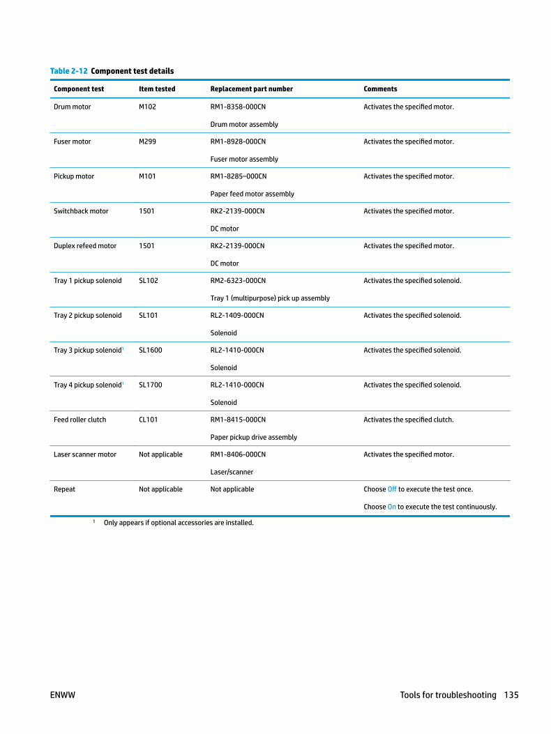
Table 2-12 Component test details
Component test Item tested Replacement part number Comments
Drum motor M102 RM1-8358-000CN
Drum motor assembly
Activates the specified motor.
Fuser motor M299 RM1-8928-000CN
Fuser motor assembly
Activates the specified motor.
Pickup motor M101 RM1-8285–000CN
Paper feed motor assembly
Activates the specified motor.
Switchback motor 1501 RK2-2139-000CN
DC motor
Activates the specified motor.
Duplex refeed motor 1501 RK2-2139-000CN
DC motor
Activates the specified motor.
Tray 1 pickup solenoid SL102 RM2-6323-000CN
Tray 1 (multipurpose) pick up assembly
Activates the specified solenoid.
Tray 2 pickup solenoid SL101 RL2-1409-000CN
Solenoid
Activates the specified solenoid.
Tray 3 pickup solenoid1 SL1600 RL2-1410-000CN
Solenoid
Activates the specified solenoid.
Tray 4 pickup solenoid1 SL1700 RL2-1410-000CN
Solenoid
Activates the specified solenoid.
Feed roller clutch CL101 RM1-8415-000CN
Paper pickup drive assembly
Activates the specified clutch.
Laser scanner motor Not applicable RM1-8406-000CN
Laser/scanner
Activates the specified motor.
Repeat Not applicable Not applicable Choose Off to execute the test once.
Choose On to execute the test continuously.
1 Only appears if optional accessories are installed.
ENWW Tools for troubleshooting 135

DiagramsUse the diagrams in this section to identify printer components.
Diagrams: Block diagrams
Use the diagrams in this section to identify printer sensors, switches, and assemblies.
Sensors and switches
Figure 2-50 Printer base, sensors and switches block diagram
PS907PS107
PS101
PS102PS105
PS106PS108
PS103PS700PS699
SW102
PS104
Separation roller
Pickup roller
Pickup arm
Lifter
Lifting plate
Transfer roller
Photosensitive drum
Lifting plate
Pre-transfer roller
Registration shutter
Feed roller
Feed roller
Fixing sleeve
Pressure roller
Face-down delivery roller
Table 2-13 Product base, sensors and switches block diagram
Sensor Description Sensor Description
PS101 Tray (cassette) media presence senor PS108 Media width sensor 2
PS102 Pre-feed sensor PS699 Fuser pressure release sensor
PS103 Top-of-page (TOP) sensor PS700 Fuser delivery sensor
PS104 Face-down tray media full sensor PS907 Media stack surface sensor 2
PS105 Tray 1 (multipurpose tray) media presence sensor TH3 Environmental sensor
PS106 Media width sensor 1 SW102 Media size detection switch (Tray 2)
PS107 Media stack surface sensor 1
136 Chapter 2 Solve problems ENWW
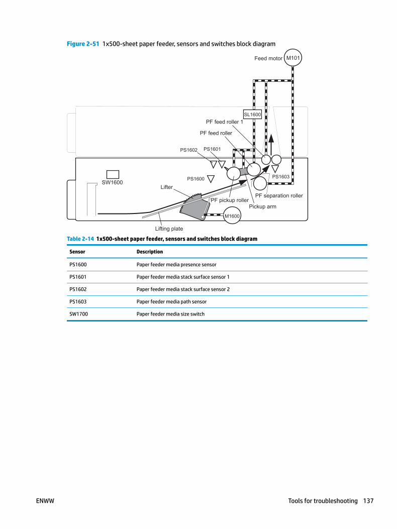
Figure 2-51 1x500-sheet paper feeder, sensors and switches block diagram
SW1600
PS1601PS1602
PS1600 PS1603
PF separation rollerPF pickup roller
PF feed roller
Pickup arm
Lifter
Lifting plate
Feed motor
M1600
SL1600
M101
PF feed roller 1
Table 2-14 1x500-sheet paper feeder, sensors and switches block diagram
Sensor Description
PS1600 Paper feeder media presence sensor
PS1601 Paper feeder media stack surface sensor 1
PS1602 Paper feeder media stack surface sensor 2
PS1603 Paper feeder media path sensor
SW1700 Paper feeder media size switch
ENWW Tools for troubleshooting 137
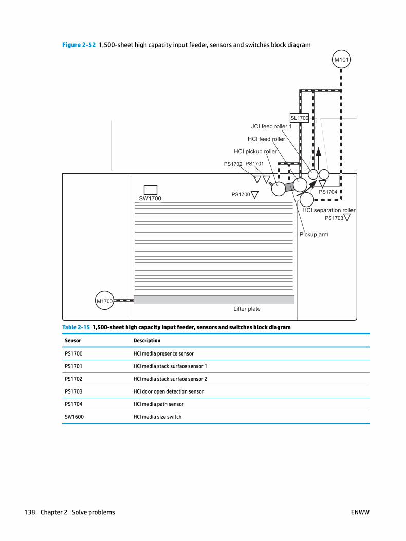
Figure 2-52 1,500-sheet high capacity input feeder, sensors and switches block diagram
SW1700
PS1701PS1702
PS1700 PS1704
PS1703HCI separation roller
HCI pickup roller
HCI feed roller
Pickup arm
Lifter plate
JCI feed roller 1SL1700
M101
M1700
Table 2-15 1,500-sheet high capacity input feeder, sensors and switches block diagram
Sensor Description
PS1700 HCI media presence sensor
PS1701 HCI media stack surface sensor 1
PS1702 HCI media stack surface sensor 2
PS1703 HCI door open detection sensor
PS1704 HCI media path sensor
SW1600 HCI media size switch
138 Chapter 2 Solve problems ENWW

Figure 2-53 Envelope feeder, sensors and switches block diagram
Envelope pickup roller
Upper separation roller
Lower separation roller
Feed roller
Torquelimiter
M1800
PS1800
PS1802
Table 2-16 Envelope feeder, sensors and switches block diagram
Sensor Description
PS1800 Envelope feeder media presence sensor
PS1802 Envelope feeder multi-feed sensor
ENWW Tools for troubleshooting 139

Figure 2-54 Duplexer, sensors and switches block diagram
M1502
M1501
PS1501
PS1502PS1503
PS700
Duplex feed roller
Face-downdelivery roller
CW
CCW
Side registration guide
Table 2-17 Duplexer, sensors and switches block diagram
Sensor Description
PS1501 Face-up sensor
PS1502 Duplexer media re-pick sensor
PS1503 Side registration guide home-position sensor
140 Chapter 2 Solve problems ENWW
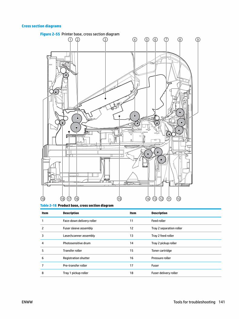
Cross section diagrams
Figure 2-55 Printer base, cross section diagram1 2 3 4 5 6 7 8
1012131415161718
9
1119
Table 2-18 Product base, cross section diagram
Item Description Item Description
1 Face-down delivery roller 11 Feed roller
2 Fuser sleeve assembly 12 Tray 2 separation roller
3 Laser/scanner assembly 13 Tray 2 feed roller
4 Photosensitive drum 14 Tray 2 pickup roller
5 Transfer roller 15 Toner cartridge
6 Registration shutter 16 Pressure roller
7 Pre-transfer roller 17 Fuser
8 Tray 1 pickup roller 18 Fuser delivery roller
ENWW Tools for troubleshooting 141
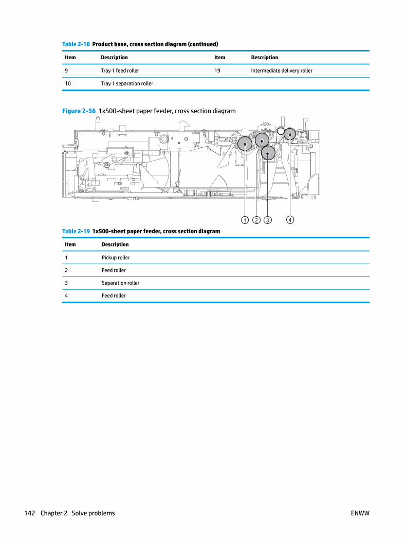
Table 2-18 Product base, cross section diagram (continued)
Item Description Item Description
9 Tray 1 feed roller 19 Intermediate delivery roller
10 Tray 1 separation roller
Figure 2-56 1x500-sheet paper feeder, cross section diagram
321 4
Table 2-19 1x500-sheet paper feeder, cross section diagram
Item Description
1 Pickup roller
2 Feed roller
3 Separation roller
4 Feed roller
142 Chapter 2 Solve problems ENWW

Figure 2-57 1,500-sheet high capacity input (HCI) feeder, cross section diagram321 4
Table 2-20 1,500-sheet high capacity input (HCI) feeder, cross section diagram
Item Description
1 Pickup roller
2 Feed roller
3 Separation roller
4 Feed roller
ENWW Tools for troubleshooting 143
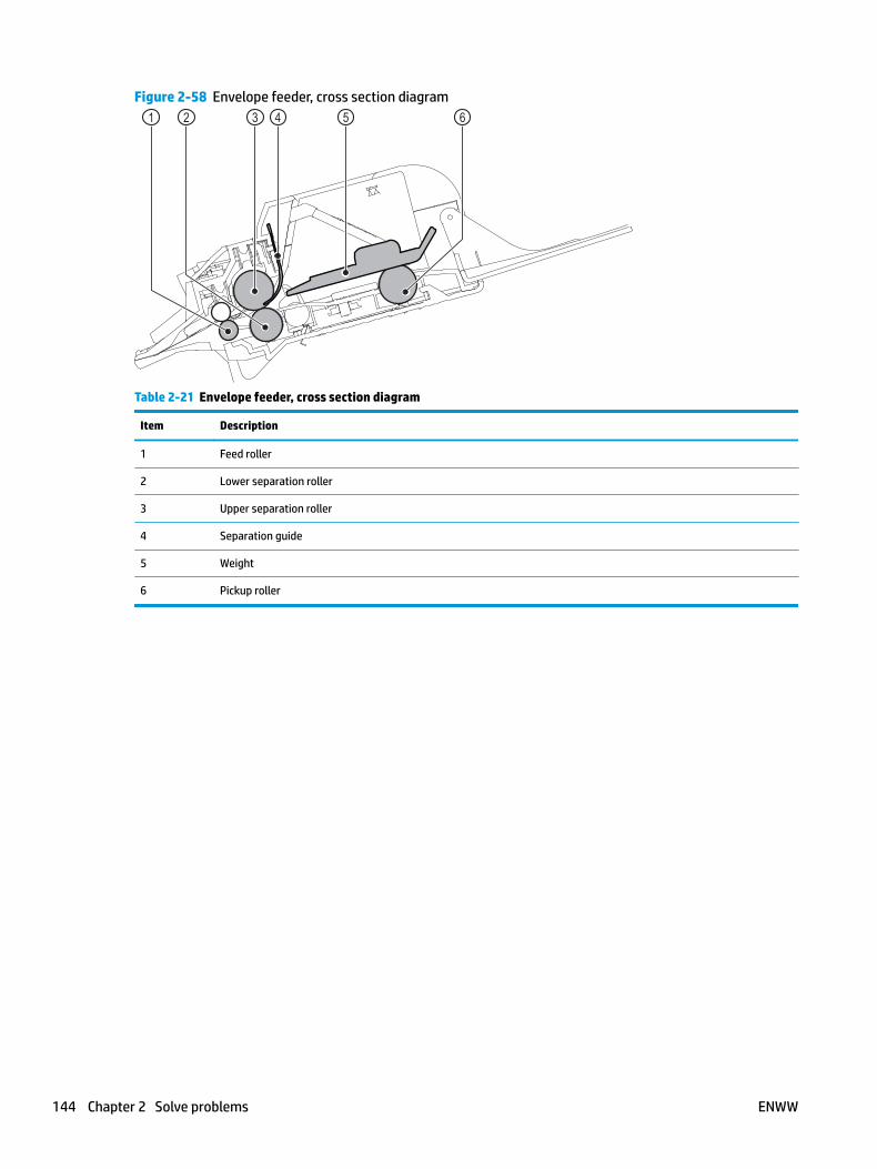
Figure 2-58 Envelope feeder, cross section diagram321 4 65
Table 2-21 Envelope feeder, cross section diagram
Item Description
1 Feed roller
2 Lower separation roller
3 Upper separation roller
4 Separation guide
5 Weight
6 Pickup roller
144 Chapter 2 Solve problems ENWW

Figure 2-59 Duplexer, cross section diagram
2
1
Table 2-22 Duplexer, cross section diagram
Item Description
1 Oblique rollers
2 Re-pickup rollers
Figure 2-60 Tray, cross section diagram1
Table 2-23 Tray, cross section diagram
Item Description
1 Separation roller
ENWW Tools for troubleshooting 145
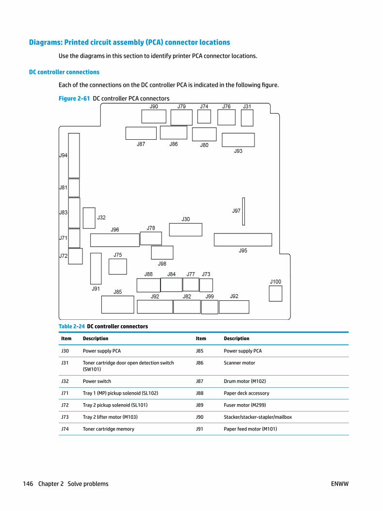
Diagrams: Printed circuit assembly (PCA) connector locations
Use the diagrams in this section to identify printer PCA connector locations.
DC controller connections
Each of the connections on the DC controller PCA is indicated in the following figure.
Figure 2-61 DC controller PCA connectors
Table 2-24 DC controller connectors
Item Description Item Description
J30 Power supply PCA J85 Power supply PCA
J31 Toner cartridge door open detection switch (SW101)
J86 Scanner motor
J32 Power switch J87 Drum motor (M102)
J71 Tray 1 (MP) pickup solenoid (SL102) J88 Paper deck accessory
J72 Tray 2 pickup solenoid (SL101) J89 Fuser motor (M299)
J73 Tray 2 lifter motor (M103) J90 Stacker/stacker-stapler/mailbox
J74 Toner cartridge memory J91 Paper feed motor (M101)
146 Chapter 2 Solve problems ENWW

Table 2-24 DC controller connectors (continued)
Item Description Item Description
J75 Fan 102 J92 Tray 2 media present sensor (PS101)
Tray 2 media stack sensor 1 (PS107)
Tray 2 media stack sensor 2 (PS907)
J76 Delivery bin detection switch J93 Laser/scanner
J77 Media feed clutch J94 Pre-feed sensor (PS102)
Top-of-page sensor (PS103)
Media width sensor 2 (PS108)
Media width sensor 1 (PS106)
J78 Interlock switch J95 Power supply PCA
J79 Fan 104 J96 Power supply PCA
J80 Empty J97 Formatter PCA
J81 Tray 1 (MP) media out sensor J98 Power supply PCA
J82 Fuser pressure release sensor
Fuser output sensor
Main thermistor
Sub thermistor
J99 Tray 2 media size switches (SW102)
J83 Envelope feeder accessory J100 Empty
J84 Duplexer accessory
ENWW Tools for troubleshooting 147
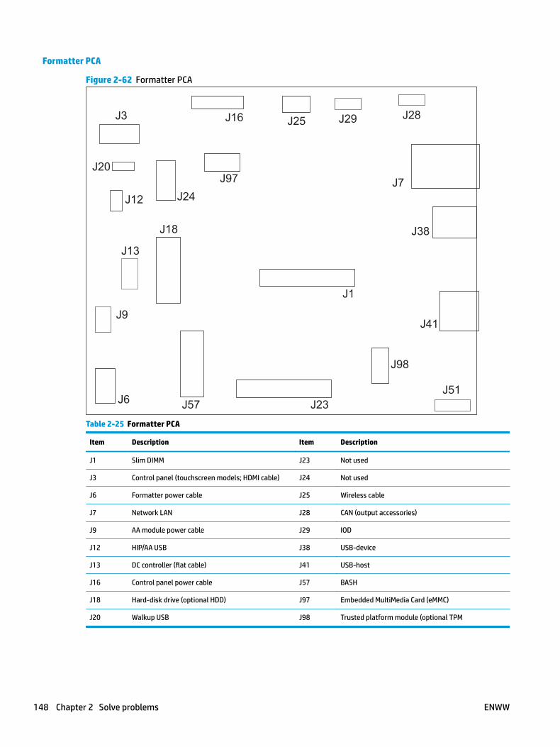
Formatter PCA
Figure 2-62 Formatter PCA
J3
J20
J12
J9
J1
J41
J38
J7
J16 J25 J29
J6
J24
J23
J98
J97
J57
J28
J18
J13
J51
Table 2-25 Formatter PCA
Item Description Item Description
J1 Slim DIMM J23 Not used
J3 Control panel (touchscreen models; HDMI cable) J24 Not used
J6 Formatter power cable J25 Wireless cable
J7 Network LAN J28 CAN (output accessories)
J9 AA module power cable J29 IOD
J12 HIP/AA USB J38 USB-device
J13 DC controller (flat cable) J41 USB-host
J16 Control panel power cable J57 BASH
J18 Hard-disk drive (optional HDD) J97 Embedded MultiMedia Card (eMMC)
J20 Walkup USB J98 Trusted platform module (optional TPM
148 Chapter 2 Solve problems ENWW

Printer base connectors
Figure 2-63 Printer base connectors
ENWW Tools for troubleshooting 149

1x500-sheet feeder connectors
Figure 2-64 1x500-sheet feeder connectors
1,500-sheet high-capacity feeder connectors
Figure 2-65 1,500-sheet high-capacity feeder connectors
150 Chapter 2 Solve problems ENWW
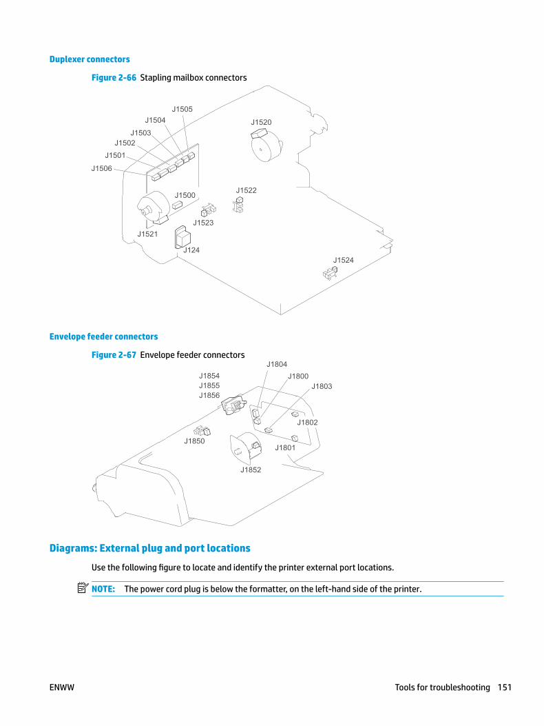
Duplexer connectors
Figure 2-66 Stapling mailbox connectors
Envelope feeder connectors
Figure 2-67 Envelope feeder connectors
Diagrams: External plug and port locations
Use the following figure to locate and identify the printer external port locations.
NOTE: The power cord plug is below the formatter, on the left-hand side of the printer.
ENWW Tools for troubleshooting 151
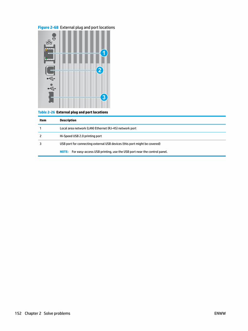
Figure 2-68 External plug and port locations
1
3
2
Table 2-26 External plug and port locations
Item Description
1 Local area network (LAN) Ethernet (RJ-45) network port
2 Hi-Speed USB 2.0 printing port
3 USB port for connecting external USB devices (this port might be covered)
NOTE: For easy-access USB printing, use the USB port near the control panel.
152 Chapter 2 Solve problems ENWW
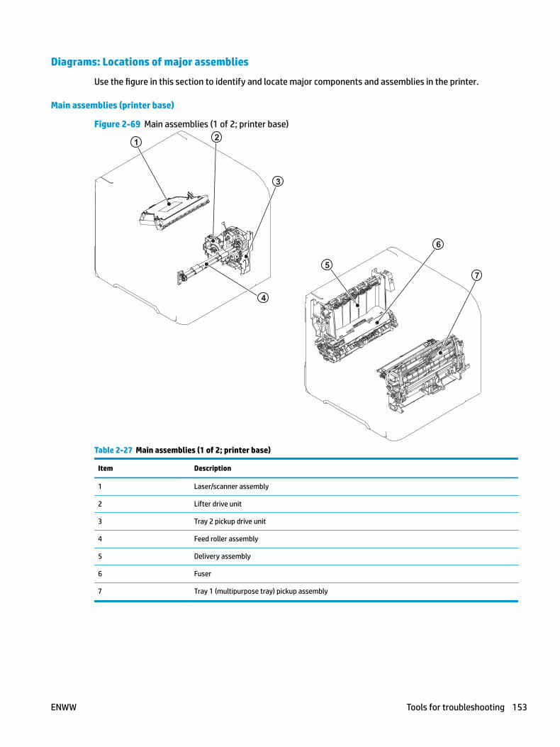
Diagrams: Locations of major assemblies
Use the figure in this section to identify and locate major components and assemblies in the printer.
Main assemblies (printer base)
Figure 2-69 Main assemblies (1 of 2; printer base)
1 2
6
7
3
4
5
Table 2-27 Main assemblies (1 of 2; printer base)
Item Description
1 Laser/scanner assembly
2 Lifter drive unit
3 Tray 2 pickup drive unit
4 Feed roller assembly
5 Delivery assembly
6 Fuser
7 Tray 1 (multipurpose tray) pickup assembly
ENWW Tools for troubleshooting 153
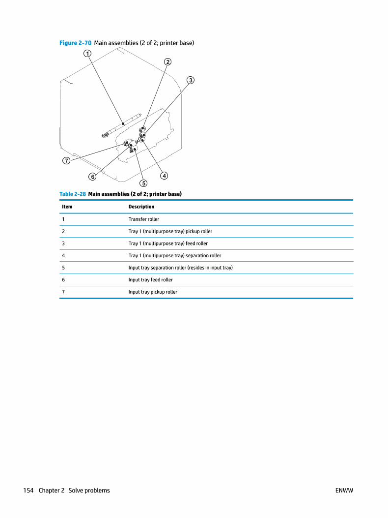
Figure 2-70 Main assemblies (2 of 2; printer base)
12
3
45
7
6
Table 2-28 Main assemblies (2 of 2; printer base)
Item Description
1 Transfer roller
2 Tray 1 (multipurpose tray) pickup roller
3 Tray 1 (multipurpose tray) feed roller
4 Tray 1 (multipurpose tray) separation roller
5 Input tray separation roller (resides in input tray)
6 Input tray feed roller
7 Input tray pickup roller
154 Chapter 2 Solve problems ENWW
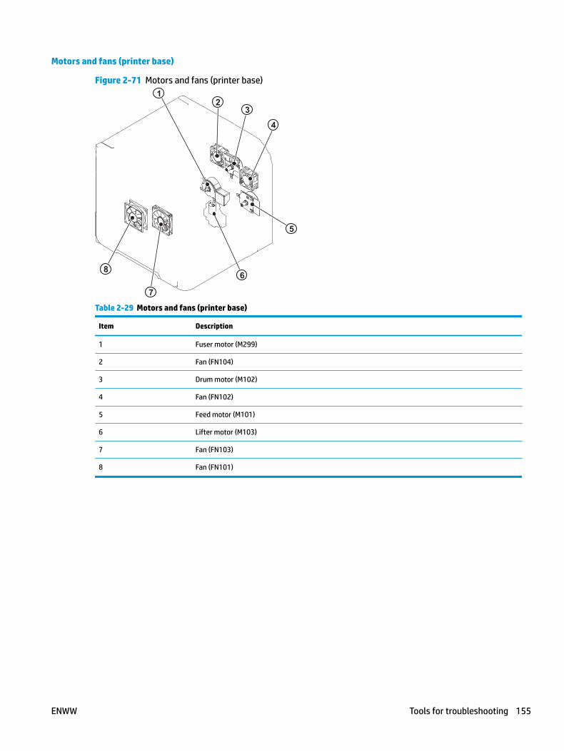
Motors and fans (printer base)
Figure 2-71 Motors and fans (printer base)
21
3
4
5
6
7
8
Table 2-29 Motors and fans (printer base)
Item Description
1 Fuser motor (M299)
2 Fan (FN104)
3 Drum motor (M102)
4 Fan (FN102)
5 Feed motor (M101)
6 Lifter motor (M103)
7 Fan (FN103)
8 Fan (FN101)
ENWW Tools for troubleshooting 155

Printed circuit assemblies (PCAs; printer base)
Figure 2-72 PCAs (printer base)
12
Table 2-30 PCAs (printer base)
Item Description
1 Power supply PCA
2 DC controller PCA
156 Chapter 2 Solve problems ENWW
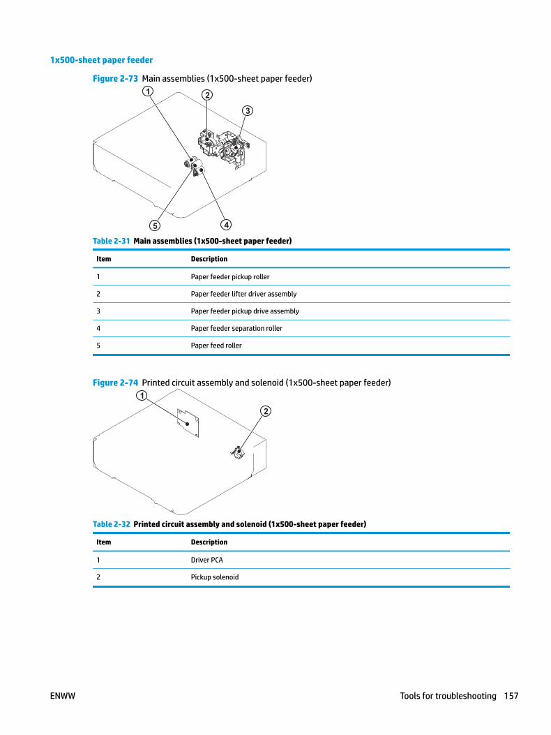
1x500-sheet paper feeder
Figure 2-73 Main assemblies (1x500-sheet paper feeder)
2
3
4
1
5
Table 2-31 Main assemblies (1x500-sheet paper feeder)
Item Description
1 Paper feeder pickup roller
2 Paper feeder lifter driver assembly
3 Paper feeder pickup drive assembly
4 Paper feeder separation roller
5 Paper feed roller
Figure 2-74 Printed circuit assembly and solenoid (1x500-sheet paper feeder)1
2
Table 2-32 Printed circuit assembly and solenoid (1x500-sheet paper feeder)
Item Description
1 Driver PCA
2 Pickup solenoid
ENWW Tools for troubleshooting 157
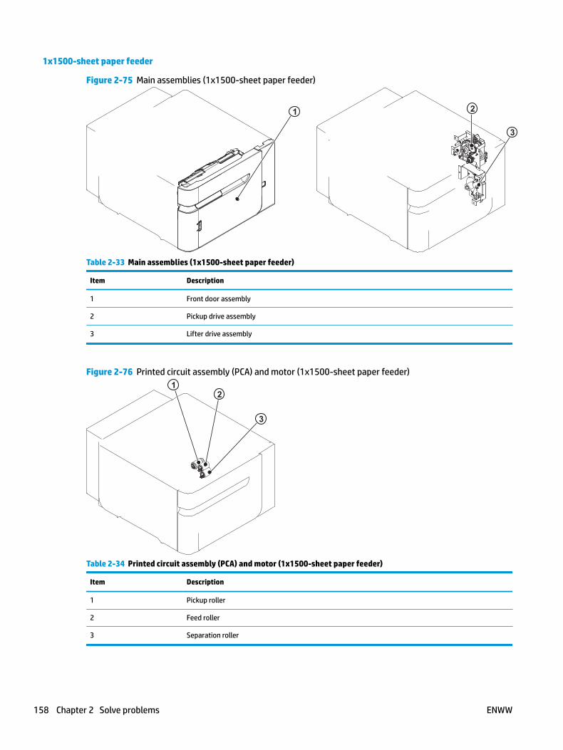
1x1500-sheet paper feeder
Figure 2-75 Main assemblies (1x1500-sheet paper feeder)
1 2
3
Table 2-33 Main assemblies (1x1500-sheet paper feeder)
Item Description
1 Front door assembly
2 Pickup drive assembly
3 Lifter drive assembly
Figure 2-76 Printed circuit assembly (PCA) and motor (1x1500-sheet paper feeder)1
3
2
Table 2-34 Printed circuit assembly (PCA) and motor (1x1500-sheet paper feeder)
Item Description
1 Pickup roller
2 Feed roller
3 Separation roller
158 Chapter 2 Solve problems ENWW
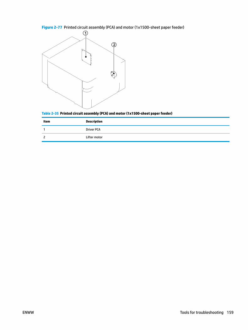
Figure 2-77 Printed circuit assembly (PCA) and motor (1x1500-sheet paper feeder)1
2
Table 2-35 Printed circuit assembly (PCA) and motor (1x1500-sheet paper feeder)
Item Description
1 Driver PCA
2 Lifter motor
ENWW Tools for troubleshooting 159
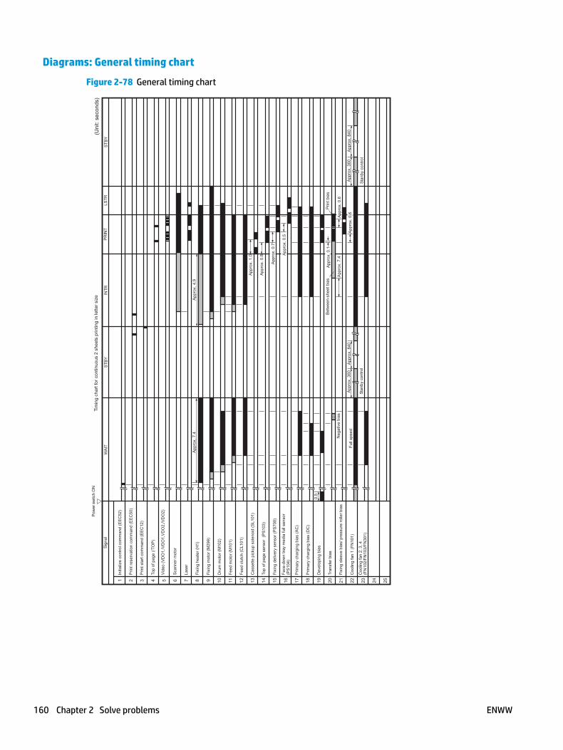
Diagrams: General timing chart
Figure 2-78 General timing chart
160 Chapter 2 Solve problems ENWW
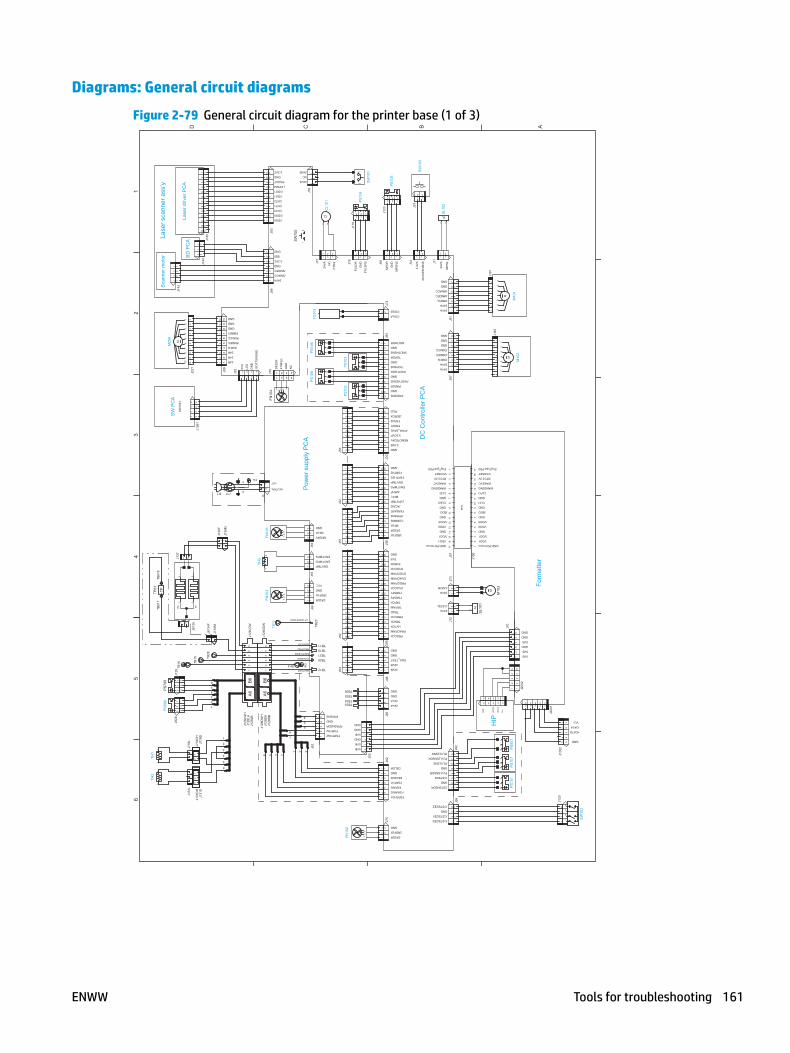
Diagrams: General circuit diagrams
Figure 2-79 General circuit diagram for the printer base (1 of 3)
A
65
43
21
BCD
+DATA
GND
Vcc
-DATA
25
43
1
12345
GND
5VB
5VB
GND
J200
2
5VB
GND
Form
atte
r
12
3
HIP
23
+DA
TA
-DA
TA
Vcc
GN
D
12
31
54
12
12
54
332
14
3
1
12345
2345
65
GND,PD1mono
J100
GND
CLFI
GND
/BDO
GND
/VDO0
VDO0
GND
/VDO1
VDO1
1110
98
76
54
23
1
EngType,PD0
WAKEVC
WAKEENG
CLFO
1514
1312
/VCRSET
RTC3.3V
1716
21
43
21
/CSTSIZE2
GND
/CSTSIZE1
/CSTSIZE0
CSTSNSDR
GND
/CSTSNS
65
43
PLVLSNSDR
GND
/PLVLSNS
87
PLVL2SNSDR
/PLVL2SNS
24VA
24VA
/CSTSL
/LMON
21
21
FFC
J97
CLEO
GND,PD1mono
VDO1
VDO0
GND
GND
/BDO
/VDO0
GND
GND
/VDO1
78
917
1615
1413
1110
12
CLEI
WAKEVC
WAKEENG
45
6
DC
Con
trolle
r PC
A
EngType,PD0
/VCRSET
RTC3.3V
12
3
24VA
24VA
32
1
/DMFG
76
54
GND
GND
/DMACC
/DMDEC
24VA
24VA
GND
65
43
21
8
/MMFG
/MMDEC
/MMACC
GND
24V
A
/MP
SL
7
GND
J71
2 2121
/DO
OP
EN
SN
SS
W10
3
1
FSRTHG1
FSRARIG
FSRARI
FSRTH1
32
14
56
7
2NDFLK
DF2DR
DELSNS
GND
12
3
DELDR
GND
ENG_TEST
GND
GND
24VA
43
21
24VA
GND
1
GND
24VB
24VB2
34
5
PRACPWM
DVACPWM
DVDCPWM
PRDCPWM
32
14
HVTCK
TRNCK
PRACCK
TRPWM
1514
1312
1110
9
DVDCCK
56
78
TRPCK
TRAD
PRDCCK
TNRSP2
TNRSP1
DVACCK
LVPSTMP
/FPRSNS
FSRSAFE
5VA
GND
1817
16
5VBON
/AC200
96
54
38
72
1
3RDFLK
DF2DR
MFLK
CURRMS
MFFL
ENVTMPG
REMOTE24V
/PWR_SAVE
FSRTH2G
1011
12
ENVTMP
/MFHF
3.3OVP
3.3VB
GND
1514
13
FSRD1
GND
54
32
1
FSRTH2
/PRESNS
/WIDTH2SNS
WIDTH2DR
/TOPSNS
/ZEROX
/RLD
FSRD2
98
76
45
67
89
1011
12
GND
PREDR
GND
TOPDR
GND
WIDTHDR
/WIDTHSNS
12
3
GND
21
COILB
COILA
3.3V
A
1
MP
DR
MP
SN
S
GN
D
21 3
2123
GND
5VB
GND
5VB
5VB
GND
21
65
43FSRTHG2
FSRTH2
FPRSNSDR
GND
FPRSNS
54
32
14
ENVTMP
1716
1518
3RDFLK
1413
1211
109
87
65
32
1ENVTMPG
87
12
34
56
7
ENVTMPG
54
63
21
57
89
61
23
4P
S10
3P
S10
2
31
2
32
13
12
12
324
VA
/TR
CL
FULD
R
NC
321 1321
FULS
NS
GN
D
32
3 12
54
32
1
FG
FILM BIAS
HEATER1
HEATERC
KAATU BIAS
HEATER2
N.C.
GND
DF2DR
41
32
13
24
TR GUIDE BIAS
J66
J63
GND
MFLK
MFDRV
32
13
21
32
13
21
J64
NEUTRAL
HOT
Pow
er s
uppl
y P
CA
PS
108
DF2
DR
4TH
FLK
43
NC
GN
D
21
4321
PS
106
J77
/SMDEC
24VA
/SMACC
/VDO0
VDO0
3.3VC
GND
/BDI
GND
32
1
CNT2
CNT0
CNT1
/VDO1
VDO1
24VB3.3VC
LPPWM
PDOUT
GND
24VA
NC
12
FG
N
H
J795V
A
24R
24R
/SO
FTS
WS
NS
GN
D
LED
4321
21
24R
/FMDEC
/FMFG
54
3
FMREV
GND
/FMACC
GND109
87
6
GND
32
17
65
42
15
43
1110
98
76
12
32
1
12
34
42
3
1312
1011
12
3
1
BD
PC
A
78
9
Lase
r driv
er P
CA
12
34
56
SW
1061
SW
PC
A
Sca
nner
mot
orLa
ser s
cann
er a
ss’y
3
1
2
4
SW
102
12
34
J120
12
34
5J1
052
12345
J200
1
PS
101
PS
107
PS
907
34
56
12
12 S
L
SL1
012
1
M
M10
3
J70
76
53
21
4 M
M10
2
12
34
56
78
76
53
21
4 M
M10
1
12
34
56
7J1
87J1
91
12
34
J99
12
34
56
78
J92
12
J72
12
J73
12
34
56
78
12
34
56
7J8
7
1 2
1 2
SL
J91
12
SL1
02
12
34
56
71
23
J75
23
41
J85
34
56
12
J82
12
34
5
J98
1817
1615
1413
1211
109
82
34
56
17
J95
1514
1312
1110
98
23
45
61
7
J96
98
23
45
61
7
J30
1211
109
82
34
56
17
12
J74
J94
1 2 3
J81
J31
123
J123
PS
105
J33
SW
101
32
1FN10
2
J55
TB34TB33
TB36
TB11TB10TB21TB20
TB12
J50
12
34
5J54
TB35
1817
1615
1413
1211
109
82
34
56
17
12
34
56
7J51
12
34
56
78J5
2
98
23
45
61
7
J53
1 2 3
J76
123
J176
21
CL
PS
104
21
CL1
01
3
12
34
5
J62
21
654
14
3 2
TB14
TB23
TB13
32
13
21
321
TG10
1
21S
W70
0
23
1
J78
J128
DA
J128
DW
H
J128
DB
J128
LAJ1
28LW
H
J128
LB
56
6
5
1
2
3
4
A6
56
41
23
B6
A6
56
41
23
B6
J128
DD
W
J128
LDW
FN10
31
2
TH3
21
J136
M
FN10
12
1
J1J150
1 2 3 4
J32
FN10
4J8
61
23
45
67
1110
98
23
45
61
7
J93
J131
DH
23
1J1
31L
12
3
J131
DJ7
78D
H1
2
J778
D
21
J778
L
12
3
23
1
TB28
11
654
12
3TB
16 TB15
21
J613
5
21
H2
21
H1
J134
M
J613
4F
21
J136
F
21
J137
J106
1
321
P1
109
82
34
56
17
J89
12
34
98
76
54
32
110
M
109
82
34
56
17
J221
J143
1312
1110
98
23
45
61
7J1
45
12
34
12
3J1
44
12
TH2
12
TH1
PS
699
J929
PS
700
J129
TB61
7TB
618
12
TPTP61
M29
9
3
ENWW Tools for troubleshooting 161
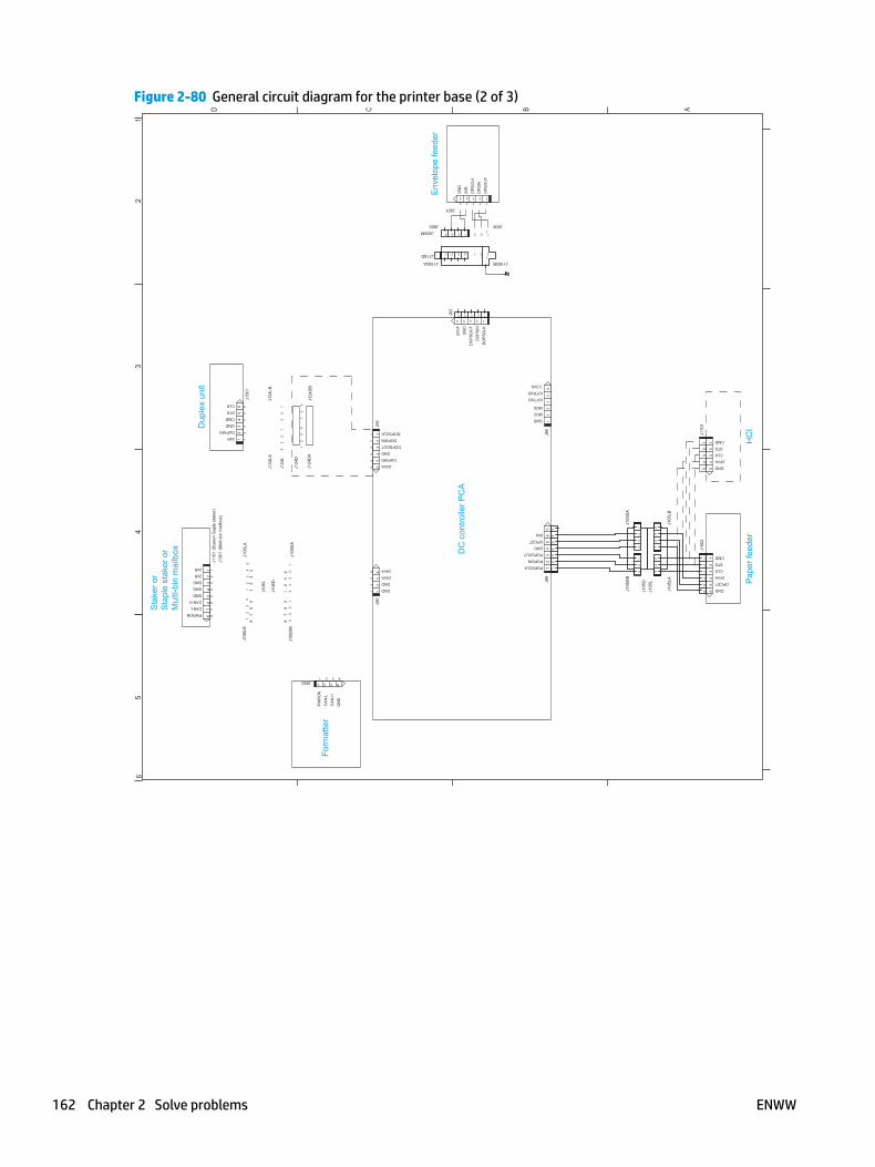
Figure 2-80 General circuit diagram for the printer base (2 of 3)
A
65
43
21
BCD
OPCST
24VA
CMD
CLK
STS
Pap
er fe
eder
GND
CMD
STS
CLK
HC
I
24VA
GND
12
34
56
J170
1
12
34
5
12
34
5
OPCST
24U
5
GND
POPSOUT
POPSIN
POPSCLK
12
34
76
IOTRXD
GND
MD0
3.3VA
15
43
26
MD2
IOTTXD
DC
con
trolle
r PC
A24
VA
DO
PS
OU
T
DO
PS
IN
DO
PS
CLK
GN
D
12345
GN
D
24R
OP
SC
LK
OP
SIN
OP
SO
UT
5 4 3 2 1
GND
GND
43
1
24VA
24VA
2
24VA
GND
DOPSOUT
DOPSIN
DOPSCLK
DUPARI
12
34
56
Env
elop
e fe
eder
Form
atte
rG
ND
PW
RO
N
CA
N-L
CA
N-H
431 2
8 84
32
1
76
54
32
1
56
7
J124
D
PWRON
CAN-L
CAN-H
GND
GND
GND
J130
1 (M
ulti-
bin
mai
lbox
)
24R
24R
76
81
23
45
12
3Dup
lex
unit
DUPARI
24R
GND
CLK
STS
CMD
45
6
Sta
ker o
rS
tapl
e st
aker
or
Mul
ti-bi
n m
ailb
ox
J105
L1
23
J105
LA
12
34
56
J160
2
12
34
J105
LB
J105
D1
23
4
J105
DA
12
3
J105
DB
12
34
56
7
J88
J80
J118DB
1 2 3 4
1234
12345J83
1
1123
1 2 3
12345
J901
J906
J90
J84
J118DA
J118D
J905MJ905
1 2 3 4J900
12
34
J124
DA
12
34
56
J124
DB
12
34
J106
DB
12
34
J106
LB
J106
L
12
34
5J1
06D
A
J106
D
12
34
5J1
06LA
12
34
56
12
341
23
4
J124
LA
J124
L
J150
1
12
3
J124
LB
12
3
12
34
56
78
J110
1 (S
take
r/ S
aple
sta
ker)
162 Chapter 2 Solve problems ENWW

Figure 2-81 General circuit diagram for the printer base (3 of 3)
A
65
43
21
BCD
<Tou
chsc
reen
Con
trol P
anel
>
NFC
Touc
hscr
een
pane
l
I2C interrupt
NFC detect
GND
I2C SCL
I2C SDA
5V NFC Switch
FPO
FPI
FPCK
/FPCS
GND
5V Switched
5VUnswitched
3.3V
CP_WAKE
GND
FG
1418
1716
1513
1211
109
87
65
4
18
13
2FG
<LC
D C
ontro
l Pan
el>
WiF
i
17161514131211
4Lin
e pa
nel (
LCD
)
Form
atte
r
987654 10
GN
D
FG5VD
ISP
LAY
FPC
K
/FP
CS
FPI
FPO
I.O.D
PC
A
1 32
CP
_WA
KE
3.3V
GN
D
TB29
TB27
34
56
12
J309
81
23
45
67
910
J308
81 2 3 4 5 6 7
81 2 3 4 5 6 7
1718
1615
1413
1211
81
23
45
67
910
J307
TB26
17 1816151413121181 2 3 4 5 6 7 9 10
J302
J303
J305
1 2 3 4 5
12345
J301
8 1234567910
J300
J304
ENWW Tools for troubleshooting 163
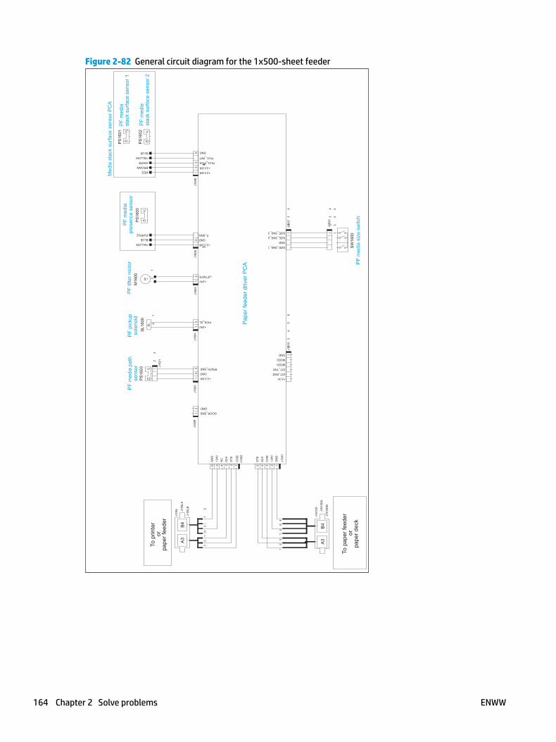
Figure 2-82 General circuit diagram for the 1x500-sheet feeder
+3.3 DR
NC
CM
D
STS
CLK
+24V
STS
CLK
CM
D
+24V
GN
D
GN
D
GND
P_SNS
+3.3 DR
+24V
PICK_SL
+3.3 DR
GND
PPATH_SNS
DOOR_SNS
GND
+24V
LIFTMTR
SIZE_SNS_1
GND
SIZE_SNS_2
SIZE_SNS_3
+3.3V
IOT_RXD
IOT_TXD
GND
GND
+3.3 DR
PLVL_INIT
PLVL_PICK
MOD2
MOD0
3A
4B
A3
B4
SL
M
BLUE
RED
WHITE
BLUE
YELLOW
YELLOW
PURPLE
To p
rinte
ror
pape
r fee
der
BROWN
12
34
12
34
56
12
21
12
3
21
34
3
41
23
12
3
12
34
12
34
123456 12345
12
12
31
21
21
21
23
5
21
To p
aper
feed
eror
pape
r dec
k
Med
ia s
tack
sur
face
sen
sor P
CA
PF
lifte
r mot
or
PS
1601
M16
00P
S16
00P
S16
02
PF
pick
upso
leno
idS
L160
0P
S16
03
PF
med
ia s
ize
switc
hS
W16
00
PF
med
iast
ack
surfa
ce s
enso
r 1
PF
med
iast
ack
surfa
ce s
enso
r 2
PF
med
ia p
ath
sens
or
PF
med
iapr
esen
ce s
enso
r
Pap
er fe
eder
driv
er P
CA
J160
1
J160
2
J105
L
J161
5D
J161
5DB
J161
5DA
J105
LA
J105
LB
J162
3
J161
0J1
607
J162
1
J160
3J1
609
J160
5J1
604
061J6061J
8
34
164 Chapter 2 Solve problems ENWW
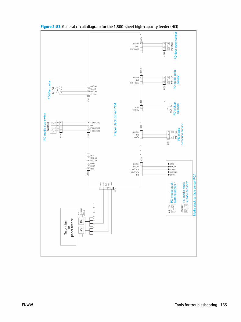
Figure 2-83 General circuit diagram for the 1,500-sheet high-capacity feeder (HCI)
LIFT_A
LIFT_ANLIFT_B
LIFT_BN
+3.3 DR
GND
GND
SIZE_SNS_3
SIZE_SNS_2
SIZE_SNS_1
GND
+3.3 DR
PPATH_SNS
DOOR_SNS
+24V
PICK_SL
GND
IOT_TXD
IOT_RXD
+3.3V
MOD2MOD0
GND+3.3 DR
GND
P_SNS
+3.3 DR
+3.3 DR
PLVL_PICK
PLVL_INIT
CM
D
STS
CLK
+24V
GN
D
SL
M
YELLOW
BLUE
WHITE
RED
BROWN
31
24
12
34
51
23
4
12345
31
24
31
24
31
24
31
24
12
31
21
23
31
23
12
31
2
12
12
34
12
3
B4
A3
To p
rinte
ror
pape
r fee
der
41
23
56
Med
ia s
tack
sur
face
sen
sor P
CA
PD
lifte
r mot
or
PD
pic
kup
sole
noid
PD
med
ia s
ize
switc
h
PD
med
ia s
tack
surfa
ce s
enso
r 1
PD
med
ia s
tack
surfa
ce s
enso
r 2
PD
med
ia p
ath
sens
orP
D m
edia
pres
ence
sen
sor
Pap
er d
eck
driv
er P
CA
PS
1701
PS
1702
PS
1704
SL1
700
PS
1703
PS
1700
SW
1700
M17
00
PD
doo
r ope
n se
nsor
J170
1
3071J2071J
J171
0
J105
L
J105
LA
J105
LB
J172
0
J170
7J1
708
J172
1
J170
4
J172
2J1
723
J170
5J1
706
ENWW Tools for troubleshooting 165

Figure 2-84 General circuit diagram for the envelope feeder
GND
24V
STS
CMD
CLK
*A
*B
A
B
CPU
GND
3.3V
M
12
34
23
45
1
13
24
23
41
32
1
12
34
23
12
34
11
23
12
3
Env
elop
epr
esen
ce s
enso
r
Env
elop
e m
ultip
lefe
ed s
enso
r
Env
elop
e fe
eder
driv
er P
CA
To p
rinte
r
M1 8
00P
S18
02
PS
1 800
Env
elop
e fe
eder
pick
up m
otor
Not
use
d
FT18
00
J180
4
MT1
800
J180
2
J185
2
J185
4J1
855
J180
1
J185
0
J180
0
J185
6
166 Chapter 2 Solve problems ENWW
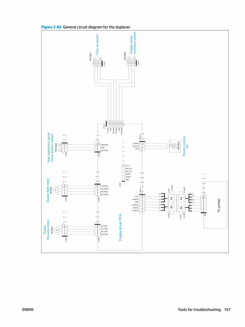
Figure 2-85 General circuit diagram for the duplexer
GND
/OPSIN
+24V
DUPARI
/OPSCLK
OPSOUT
GNDFLOCK0
FDRIVE
GND
+3.3V
MOD2
MOD0
IOT TXD
IOT RXD
GN
D
FUP
SN
SP
ICK
DR
GN
DP
ICK
SN
S
FU_D
R
IMOUTA
IMOUT/A
IMOUTB
IMOUT/B
PMOUT/B
PMOUTB
PMOUT/A
PMOUTA
REJISNS
GND
REJI_DR
B3
A4
B3
A4
M
41 2 5 63
12
31
23
45
6
65
43
21
3 2 1
12
34
32
1
32
1
42
31
43
21
13
2
12
3
12
34
12
3
12
34
56
65
43
21
65
43
21
41 2 5 63
3 2 1
3 2 1
3 2 11
23
43
21
32
1
12
34
32
14
32
14
32
1
12
34
12
34
M
Dup
lex
feed
mot
orS
ide
regi
stra
tion
guid
eho
me
posi
tion
sens
or
Dup
lex
Rev
erse
mot
orM
1502
M15
01
PS
1503
Dup
lex
cool
ing
fan
FM15
01
Face
-up
sens
or
Dup
lex
med
iare
-pic
kup
sens
or
PS
1502
PS
1501
Dup
lex
driv
er P
CA
To p
rinte
r
J152
21251J
0251J
J150
4
J150
5
J150
2
J150
1
J66
J152
4
J152
3
J150
3
J124
LA
J124
LBJ1
24L
J124
DA
J124
DB
J124
D
J150
6
J150
0
ENWW Tools for troubleshooting 167

Internal print-quality test pages
Print a configuration page
NOTE: Depending on the model, up to three pages print when printing a configuration page. In addition to the main configuration page, the HP embedded Jetdirect configuration and the wireless pages print.
Print the configuration page from a touchscreen control panel
1. From the Home screen on the printer control panel, scroll to and touch the Administration button.
2. Open the following menus:
● Reports
● Configuration/Status Pages
3. Touch Configuration Page to select it.
4. Touch the Print button to print the pages.
Print the configuration page from a LCD control panel
1. From the Home screen on the printer control panel, use the down arrow button to scroll to Administration, and then press the OK button.
2. Open the following menus:
● Reports
● Configuration/Status Pages
3. Use the down arrow button to scroll to Configuration Page, and then press the OK button to select it.
4. Use the up arrow button to scroll to Print, and then press the OK button to print the pages.
168 Chapter 2 Solve problems ENWW
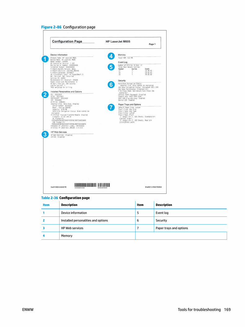
Figure 2-86 Configuration page
5
6
1
2
3
4
7
Table 2-36 Configuration page
Item Description Item Description
1 Device information 5 Event log
2 Installed personalities and options 6 Security
3 HP Web services 7 Paper trays and options
4 Memory
ENWW Tools for troubleshooting 169
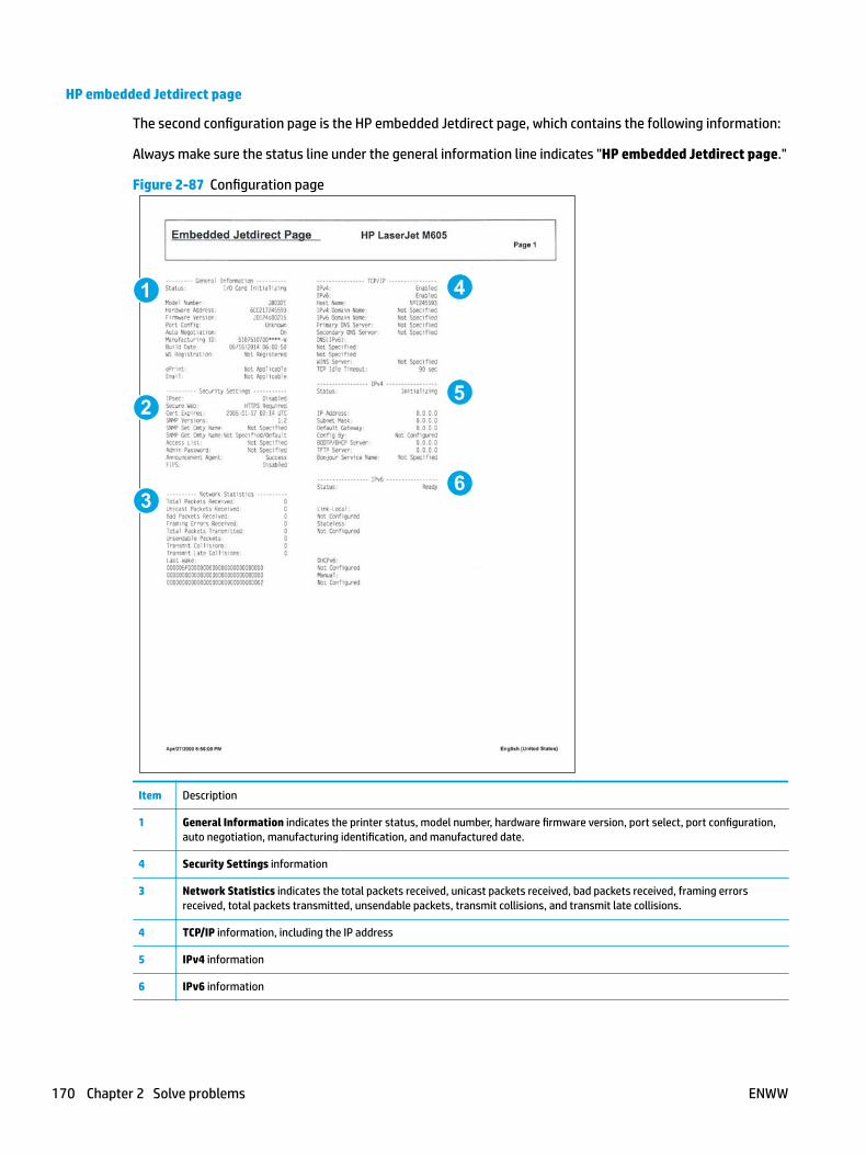
HP embedded Jetdirect page
The second configuration page is the HP embedded Jetdirect page, which contains the following information:
Always make sure the status line under the general information line indicates "HP embedded Jetdirect page."
Figure 2-87 Configuration page
5
6
1
2
3
4
Item Description
1 General Information indicates the printer status, model number, hardware firmware version, port select, port configuration, auto negotiation, manufacturing identification, and manufactured date.
4 Security Settings information
3 Network Statistics indicates the total packets received, unicast packets received, bad packets received, framing errors received, total packets transmitted, unsendable packets, transmit collisions, and transmit late collisions.
4 TCP/IP information, including the IP address
5 IPv4 information
6 IPv6 information
170 Chapter 2 Solve problems ENWW
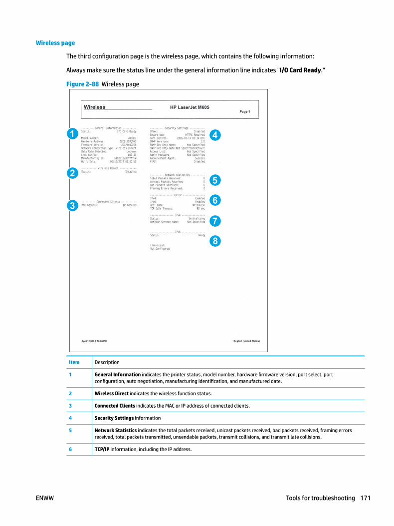
Wireless page
The third configuration page is the wireless page, which contains the following information:
Always make sure the status line under the general information line indicates "I/O Card Ready."
Figure 2-88 Wireless page
5
6
1
2
3
4
8
7
Item Description
1 General Information indicates the printer status, model number, hardware firmware version, port select, port configuration, auto negotiation, manufacturing identification, and manufactured date.
2 Wireless Direct indicates the wireless function status.
3 Connected Clients indicates the MAC or IP address of connected clients.
4 Security Settings information
5 Network Statistics indicates the total packets received, unicast packets received, bad packets received, framing errors received, total packets transmitted, unsendable packets, transmit collisions, and transmit late collisions.
6 TCP/IP information, including the IP address.
ENWW Tools for troubleshooting 171

7 IPv4 information.
8 IPv6 information.
172 Chapter 2 Solve problems ENWW

Finding important information on the configuration pages
Certain information, such as the firmware date codes, the IP address, and the email gateways, is especially helpful while servicing the printer. This information is on the various configuration pages.
Table 2-39 Important information on the configuration pages
Type of information Specific information Configuration page
Firmware date codes
When performing a remote firmware upgrade procedure, all of these firmware components are upgraded.
DC controller Look on the main configuration page, under “Device Information.”
Firmware datecode Look on the main configuration page, under “Device Information.”
HP embedded Jetdirect firmware version Look on the HP embedded Jetdirect page, under “General Information.”
Accessories and internal storage
All optional devices that are installed on the printer should be listed on the main configuration page.
In addition, separate pages print for the optional paper handling devices and the fax accessory. These pages list more-detailed information for those devices.
Embedded HP Jetdirect Look on the main configuration page, under “Installed Personalities and Options.” Shows model and ID.
Total RAM Look on the main configuration page, under “Memory.”
Duplex unit Look on the main configuration page, under “Paper Trays and Options.”
Additional 500-sheet feeders Additional 500-sheet feeders Look on the main configuration page, under “Paper Trays and Options.”
Engine cycles and event logs
Total page counts and maintenance kit counts are important for ongoing printer maintenance.
The configuration page lists only the three most recent errors. To see a list of the 50 most recent errors, print an event log from the Diagnostics menu.
Engine cycles Look on the main configuration page, under “Device Information.”
Event-log information Event-log information Look on the main configuration page, under “Event Log.”
ENWW Tools for troubleshooting 173

Print a fuser test page
Use the fuser test page to evaluate problems with fuser print quality.
Print a fuser test page from a touchscreen control panel
1. From the Home screen on the printer control panel, scroll to and touch the Administration button.
2. Open the following menus:
● Troubleshooting
● Print Quality Pages
● Fuser Test Page
3. Touch the Print button.
Print a fuser test page from a LCD control panel
1. From the Home screen on the printer control panel, use the down arrow button to scroll to Administration, and then press the OK button.
2. Use the arrow down button to scroll to Troubleshooting, and then press the OK button.
3. If necessary, use the arrow down button to scroll to Print Quality Pages, and then press the OK button to start the calibration process.
4. If necessary, use the down arrow button to scroll to Fuser Test Page, and then press the OK button to print the page.
174 Chapter 2 Solve problems ENWW

Figure 2-89 Print a fuser test page
ENWW Tools for troubleshooting 175
Print a cleaning page
Print the cleaning from a touchscreen control panel
1. From the Home screen on the printer control panel, scroll to and touch the Device Maintenance button.
2. Open the following menus:
● Calibration/Cleaning
3. Use the to scroll to Cleaning Page, and then press the OK
4. The cleaning process can take several minutes. When it is finished, discard the printed page.
Print the cleaning page from a LCD control panel
1. From the Home screen on the printer control panel, use the down arrow button to scroll to Device Maintenance, and then press the OK button.
2. Use the down arrow button to scroll to Calibration/Cleaning, and then press the OK button.
3. If necessary, use the down arrow button to scroll to Cleaning, and then press the OK button to print the page.
4. Follow the instruction on the printed cleaning page to finish the cleaning page process.
Enable and configure auto cleaning
Use the procedure in this section to enable and configure the automatic cleaning function.
To enable the auto cleaning function from a touchscreen control panel
NOTE: M605x and M606x models only.
1. From the Home screen on the printer control panel, scroll to and touch the Device Maintenance button.
2. Open the following menus:
● Calibration/Cleaning
● Auto Cleaning
3. Select the Enable item, and then touch the Save button.
176 Chapter 2 Solve problems ENWW

Control-panel menus
Administration menu
You can perform basic printer setup by using the Administration menu. Use the HP Embedded Web Server for more advanced printer setup. To open the HP Embedded Web Server, enter the printer IP address or host name in the address bar of a Web browser.
Reports menu
To display: At the printer control panel, select the Administration menu, and then select the Reports menu.
NOTE: For the M605x and M606x models, use the Print button to print the report.
For all other models, use the up arrow button or down arrow button to highlight the report, and then press the OK button. Then use the button to highlight Print, and then press the OK button. to print the report.
Table 2-40 Reports menu
First level Second level Values Description
Configuration/Status Pages Administration Menu Map Shows a map of the entire Administration menu and the selected values for each setting.
Current Settings Page Print a summary of the current settings for the printer. This might be helpful if you plan to make changes and need a record of the present configuration.
Configuration Page Shows the printer settings and installed accessories.
How to Connect Page Shows network connection information.
Supplies Status Page Shows the approximate remaining life for the supplies; reports statistics about the total number of pages and jobs processed, serial number, page counts, and maintenance information.
HP provides approximations of the remaining life for the supplies as a customer convenience. The actual remaining supply levels might be different than the approximations provided.
Usage Page Shows a count of all paper sizes that have passed through the printer; lists whether they were simplex, duplex, or monochrome; and reports the page count.
File Directory Page Shows the file name and folder name for files that are stored in the printer memory.
ENWW Tools for troubleshooting 177
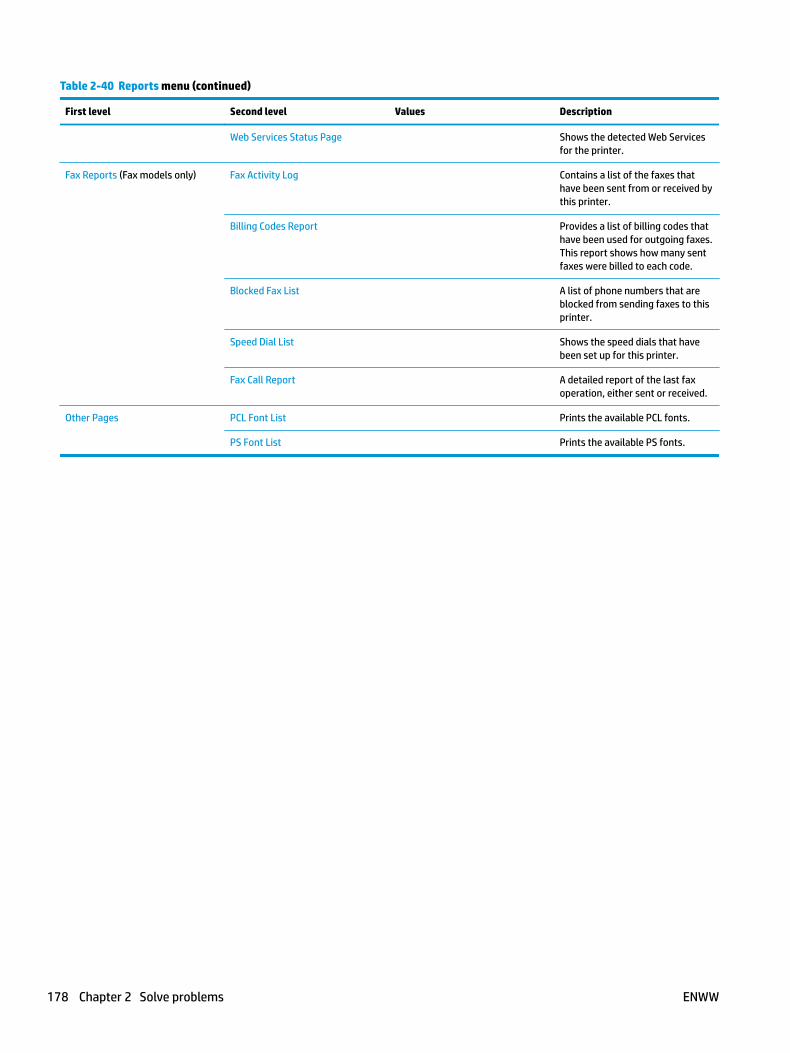
Table 2-40 Reports menu (continued)
First level Second level Values Description
Web Services Status Page Shows the detected Web Services for the printer.
Fax Reports (Fax models only) Fax Activity Log Contains a list of the faxes that have been sent from or received by this printer.
Billing Codes Report Provides a list of billing codes that have been used for outgoing faxes. This report shows how many sent faxes were billed to each code.
Blocked Fax List A list of phone numbers that are blocked from sending faxes to this printer.
Speed Dial List Shows the speed dials that have been set up for this printer.
Fax Call Report A detailed report of the last fax operation, either sent or received.
Other Pages PCL Font List Prints the available PCL fonts.
PS Font List Prints the available PS fonts.
178 Chapter 2 Solve problems ENWW
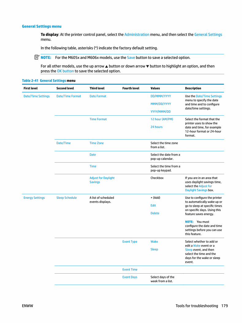
General Settings menu
To display: At the printer control panel, select the Administration menu, and then select the General Settings menu.
In the following table, asterisks (*) indicate the factory default setting.
NOTE: For the M605x and M606x models, use the Save button to save a selected option.
For all other models, use the up arrow button or down arrow button to highlight an option, and then press the OK button to save the selected option.
Table 2-41 General Settings menu
First level Second level Third level Fourth level Values Description
Date/Time Settings Date/Time Format Date Format DD/MMM/YYYY
MMM/DD/YYYY
YYYY/MMM/DD
Use the Date/Time Settings menu to specify the date and time and to configure date/time settings.
Time Format 12 hour (AM/PM)
24 hours
Select the format that the printer uses to show the date and time, for example 12-hour format or 24-hour format.
Date/Time Time Zone Select the time zone from a list.
Date Select the date from a pop-up calendar.
Time Select the time from a pop-up keypad.
Adjust for Daylight Savings
Checkbox If you are in an area that uses daylight savings time, select the Adjust for Daylight Savings box.
Energy Settings Sleep Schedule A list of scheduled events displays.
+ (Add)
Edit
Delete
Use to configure the printer to automatically wake up or go to sleep at specific times on specific days. Using this feature saves energy.
NOTE: You must configure the date and time settings before you can use this feature.
Event Type Wake
Sleep
Select whether to add or edit a Wake event or a Sleep event, and then select the time and the days for the wake or sleep event.
Event Time
Event Days Select days of the week from a list.
ENWW Tools for troubleshooting 179
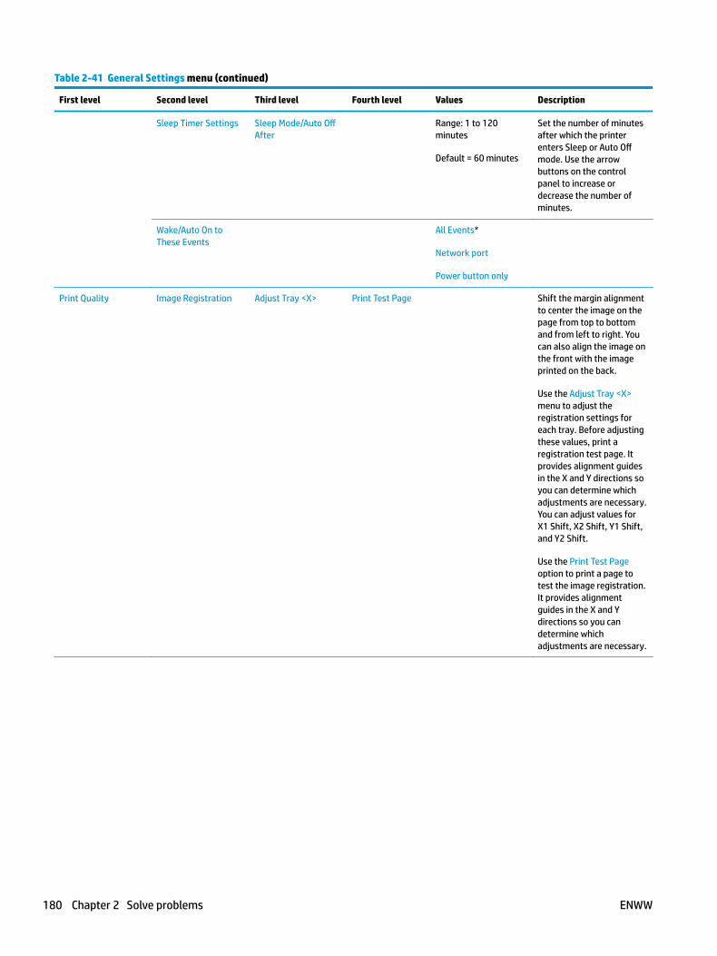
Table 2-41 General Settings menu (continued)
First level Second level Third level Fourth level Values Description
Sleep Timer Settings Sleep Mode/Auto Off After
Range: 1 to 120 minutes
Default = 60 minutes
Set the number of minutes after which the printer enters Sleep or Auto Off mode. Use the arrow buttons on the control panel to increase or decrease the number of minutes.
Wake/Auto On to These Events
All Events*
Network port
Power button only
Print Quality Image Registration Adjust Tray <X> Print Test Page Shift the margin alignment to center the image on the page from top to bottom and from left to right. You can also align the image on the front with the image printed on the back.
Use the Adjust Tray <X> menu to adjust the registration settings for each tray. Before adjusting these values, print a registration test page. It provides alignment guides in the X and Y directions so you can determine which adjustments are necessary. You can adjust values for X1 Shift, X2 Shift, Y1 Shift, and Y2 Shift.
Use the Print Test Page option to print a page to test the image registration. It provides alignment guides in the X and Y directions so you can determine which adjustments are necessary.
180 Chapter 2 Solve problems ENWW
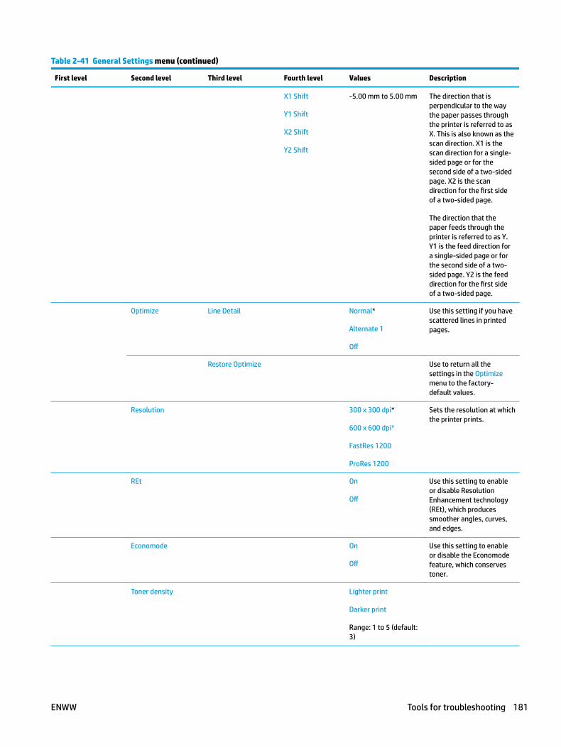
Table 2-41 General Settings menu (continued)
First level Second level Third level Fourth level Values Description
X1 Shift
Y1 Shift
X2 Shift
Y2 Shift
-5.00 mm to 5.00 mm The direction that is perpendicular to the way the paper passes through the printer is referred to as X. This is also known as the scan direction. X1 is the scan direction for a single-sided page or for the second side of a two-sided page. X2 is the scan direction for the first side of a two-sided page.
The direction that the paper feeds through the printer is referred to as Y. Y1 is the feed direction for a single-sided page or for the second side of a two-sided page. Y2 is the feed direction for the first side of a two-sided page.
Optimize Line Detail Normal*
Alternate 1
Off
Use this setting if you have scattered lines in printed pages.
Restore Optimize Use to return all the settings in the Optimize menu to the factory-default values.
Resolution 300 x 300 dpi*
600 x 600 dpi*
FastRes 1200
ProRes 1200
Sets the resolution at which the printer prints.
REt On
Off
Use this setting to enable or disable Resolution Enhancement technology (REt), which produces smoother angles, curves, and edges.
Economode On
Off
Use this setting to enable or disable the Economode feature, which conserves toner.
Toner density Lighter print
Darker print
Range: 1 to 5 (default: 3)
ENWW Tools for troubleshooting 181
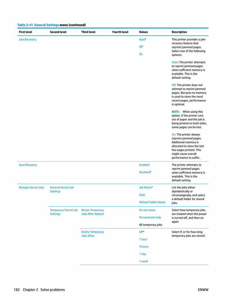
Table 2-41 General Settings menu (continued)
First level Second level Third level Fourth level Values Description
Jam Recovery Auto*
Off
On
This printer provides a jam recovery feature that reprints jammed pages. Select one of the following options:
Auto: The printer attempts to reprint jammed pages when sufficient memory is available. This is the default setting.
Off: The printer does not attempt to reprint jammed pages. Because no memory is used to store the most recent pages, performance is optimal.
NOTE: When using this option, if the printer runs out of paper and the job is being printed on both sides, some pages can be lost.
On: The printer always reprints jammed pages. Additional memory is allocated to store the last few pages printed. This might cause overall performance to suffer.
Auto Recovery Enabled
Disabled*
The printer attempts to reprint jammed pages when sufficient memory is available. This is the default setting.
Manage Stored Jobs General Stored Job Settings
Job Name*
Date
Default Folder Name
List the jobs either alphabetically or chronologically, and select a default folder for stored jobs.
Temporary Stored Job Settings
Retain Temporary Jobs After Reboot
Do not retain
Personal job only
All temporary jobs
Select how temporary jobs are treated when the power is turned off, and then on again
Delete Temporary Jobs After:
Off*
1 hour
4 hours
1 day
1 week
Select if, or for how long, temporary jobs are stored.
182 Chapter 2 Solve problems ENWW

Table 2-41 General Settings menu (continued)
First level Second level Third level Fourth level Values Description
Temporary Job Storage Limit
1 to 300 jobs Select the maximum number of stored jobs allowed.
Enable Retrieve from USB
Enabled
Disabled*
Enables the printer to open a file from a USB drive.
Hold Off Print Job Enabled*
Disabled
Enable this feature if you want to prevent print jobs from starting while a user is initiating a copy job from the control panel. Held print jobs start printing after the copy job is finished, provided that no other copy job is in the print queue.
Restore Factory Settings
Use to restore all printer settings to their factory defaults.
ENWW Tools for troubleshooting 183

General Print Settings menu
To display: At the printer control panel, select the Administration menu, and then select the General Print Settings menu.
In the following table, asterisks (*) indicate the factory default setting.
NOTE: For the M605x and M606x models, use the Save button to save a selected option.
For all other models, use the up arrow button or down arrow button to highlight an option, and then press the OK button to save the selected option.
Table 2-42 General Print Settings menu
First level Second level Values Description
Manual Feed Enabled
Disabled*
Use to enable or disable the manual-feed feature, which allows the user to feed paper into the printer by hand. When this feature is enabled, the user can select manual feed from the control panel as the paper source for a job. If a tray is not specified as part of a job, manual feed is selected.
Courier Font Regular*
Dark
Select which version of the Courier font you want to use. The factory default setting is Regular, which uses an average stroke width. The Dark setting can be used if a heavier Courier font is needed.
Wide A4 Enabled
Disabled*
Changes the printable area of A4-size paper. If you enable this option, eighty 10-pitch characters can be printed on a single line of A4 paper.
Print PS Errors Enabled
Disabled*
Use this feature to select whether a PostScript (PS) error page is printed when the printer encounters a PS error.
Print PDF Errors Enabled
Disabled*
Selects whether a PDF error page is printed when the printer encounters a PDF error.
Personality Auto*
PCL
POSTSCRIPT
Configures the default print language or personality for the printer. Normally you should not change the printer language. If you change the setting to a specific printer language, the printer does not automatically switch from one language to another unless specific software commands are sent to it.
184 Chapter 2 Solve problems ENWW

Table 2-42 General Print Settings menu (continued)
First level Second level Values Description
PCL Form Length Range: 5 – 128
Default = 60
Controls the PCL print-command options. PCL is a set of printer commands that Hewlett-Packard developed to provide access to printer features.
Use the Form Length feature to select the user-soft default vertical form length.
Orientation Portrait*
Landscape
Select the orientation that is most often used for copy or scan originals. Select the Portrait option if the short edge is at the top or select the Landscape option if the long edge is at the top.
Font Source Internal* Selects the font source for the user-soft default font. The list of available options varies depending on the installed printer options.
Font Number Range: 0 – 110
Default = 0
Specifies the font number for the user-soft default font using the source that is specified in the Font Source menu. The printer assigns a number to each font and lists it on the PCL font list. The font number displays in the Font # column of the printout.
Font Pitch Range: 0.44 – 99.99
Default = 10
If the Font Source option and the Font Number setting indicate a contour font, then use this feature to select a default pitch (for a fixed-spaced font).
Font Point Size Range: 4.00 – 999.75
Default = 12.00
If the Font Source option and the Font Number setting indicate a contour font, then use this feature to select a default point size (for a proportional-spaced font).
Symbol Set Select from a list of symbol sets. Select any one of several available symbol sets from the control panel. A symbol set is a unique grouping of all the characters in a font. The factory default value for this option is PC-8. Either PC-8 or PC-850 are recommended for line-draw characters.
ENWW Tools for troubleshooting 185

Table 2-42 General Print Settings menu (continued)
First level Second level Values Description
Append CR to LF No*
Yes
Configure whether a carriage return (CR) is appended to each line feed (LF) encountered in backwards-compatible PCL jobs (pure text, no job control). Select Yes to append the carriage return. The default setting is No. Some environments, such as UNIX, indicate a new line by using only the line-feed control code. This option allows the user to append the required carriage return to each line feed.
Suppress Blank Pages No*
Yes
This option is for users who are generating their own PCL, which could include extra form feeds that would cause blank pages to be printed. When the Yes option is selected, form feeds are ignored if the page is blank.
Media Source Mapping Standard*
Classic
Use to select and maintain input trays by number when you are not using the printer driver, or when the software program has no option for tray selection. The following options are available:
Standard: Tray numbering is based on newer HP LaserJet models.
Classic: Tray numbering is based on HP LaserJet 4 and older models.
186 Chapter 2 Solve problems ENWW
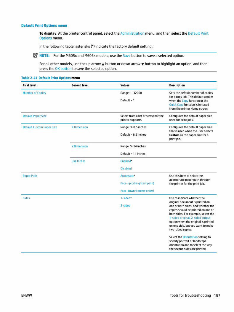
Default Print Options menu
To display: At the printer control panel, select the Administration menu, and then select the Default Print Options menu.
In the following table, asterisks (*) indicate the factory default setting.
NOTE: For the M605x and M606x models, use the Save button to save a selected option.
For all other models, use the up arrow button or down arrow button to highlight an option, and then press the OK button to save the selected option.
Table 2-43 Default Print Options menu
First level Second level Values Description
Number of Copies Range: 1–32000
Default = 1
Sets the default number of copies for a copy job. This default applies when the Copy function or the Quick Copy function is initiated from the printer Home screen.
Default Paper Size Select from a list of sizes that the printer supports.
Configures the default paper size used for print jobs.
Default Custom Paper Size X Dimension Range: 3–8.5 inches
Default = 8.5 inches
Configures the default paper size that is used when the user selects Custom as the paper size for a print job.
Y Dimension Range: 5–14 inches
Default = 14 inches
Use Inches Enabled*
Disabled
Paper Path Automatic*
Face-up (straightest path)
Face-down (correct order)
Use this item to select the appropriate paper path through the printer for the print job.
Sides 1-sided*
2-sided
Use to indicate whether the original document is printed on one or both sides, and whether the copies should be printed on one or both sides. For example, select the 1-sided original, 2-sided output option when the original is printed on one side, but you want to make two-sided copies.
Select the Orientation setting to specify portrait or landscape orientation and to select the way the second sides are printed.
ENWW Tools for troubleshooting 187
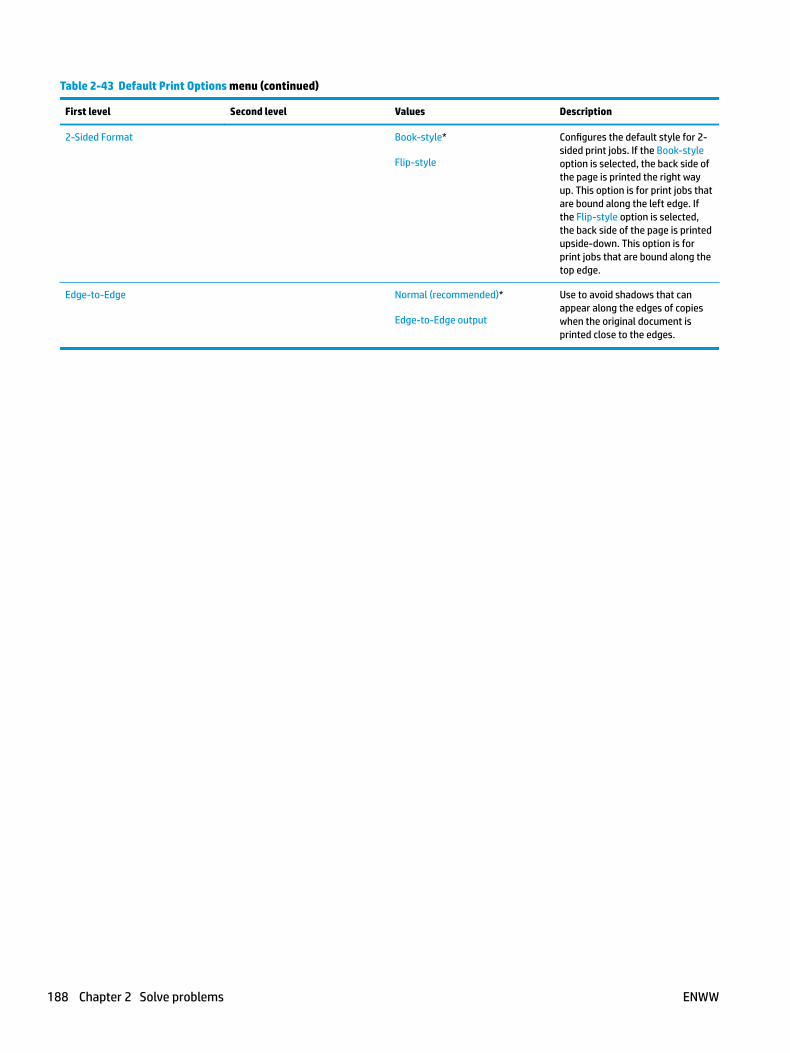
Table 2-43 Default Print Options menu (continued)
First level Second level Values Description
2-Sided Format Book-style*
Flip-style
Configures the default style for 2-sided print jobs. If the Book-style option is selected, the back side of the page is printed the right way up. This option is for print jobs that are bound along the left edge. If the Flip-style option is selected, the back side of the page is printed upside-down. This option is for print jobs that are bound along the top edge.
Edge-to-Edge Normal (recommended)*
Edge-to-Edge output
Use to avoid shadows that can appear along the edges of copies when the original document is printed close to the edges.
188 Chapter 2 Solve problems ENWW
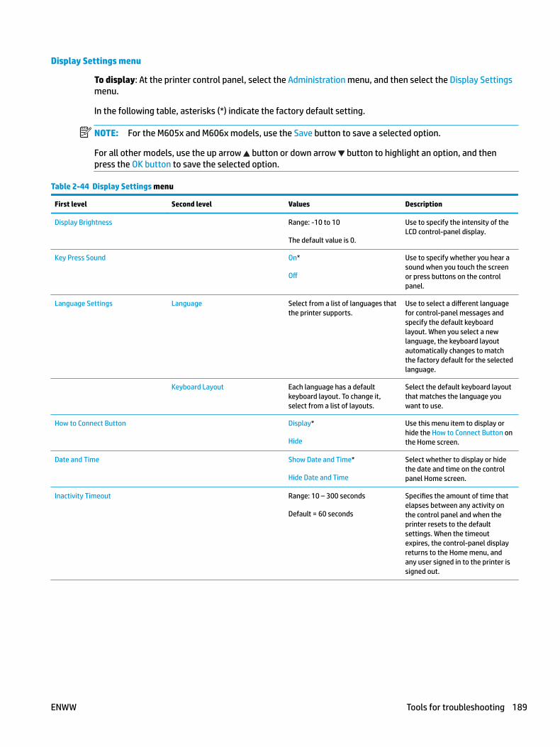
Display Settings menu
To display: At the printer control panel, select the Administration menu, and then select the Display Settings menu.
In the following table, asterisks (*) indicate the factory default setting.
NOTE: For the M605x and M606x models, use the Save button to save a selected option.
For all other models, use the up arrow button or down arrow button to highlight an option, and then press the OK button to save the selected option.
Table 2-44 Display Settings menu
First level Second level Values Description
Display Brightness Range: -10 to 10
The default value is 0.
Use to specify the intensity of the LCD control-panel display.
Key Press Sound On*
Off
Use to specify whether you hear a sound when you touch the screen or press buttons on the control panel.
Language Settings Language Select from a list of languages that the printer supports.
Use to select a different language for control-panel messages and specify the default keyboard layout. When you select a new language, the keyboard layout automatically changes to match the factory default for the selected language.
Keyboard Layout Each language has a default keyboard layout. To change it, select from a list of layouts.
Select the default keyboard layout that matches the language you want to use.
How to Connect Button Display*
Hide
Use this menu item to display or hide the How to Connect Button on the Home screen.
Date and Time Show Date and Time*
Hide Date and Time
Select whether to display or hide the date and time on the control panel Home screen.
Inactivity Timeout Range: 10 – 300 seconds
Default = 60 seconds
Specifies the amount of time that elapses between any activity on the control panel and when the printer resets to the default settings. When the timeout expires, the control-panel display returns to the Home menu, and any user signed in to the printer is signed out.
ENWW Tools for troubleshooting 189

Table 2-44 Display Settings menu (continued)
First level Second level Values Description
Clearable Warnings On
Job*
Use this feature to set the period that a clearable warning displays on the control panel. If the On setting is selected, clearable warnings appear until the Clearable Warnings button is pressed. If the Job setting is selected, clearable warnings stay on the display during the job that generated the warning and disappear from the display when the next job starts.
Continuable Events Auto-continue (10 seconds)*
Touch OK to continue
Use this option to configure the printer behavior when the printer encounters certain errors. If the Auto-continue (10 seconds) option is selected, the job will continue after 10 seconds. If the Touch OK to continue option is selected, the job will stop and require the user to press the OK button before continuing.
190 Chapter 2 Solve problems ENWW
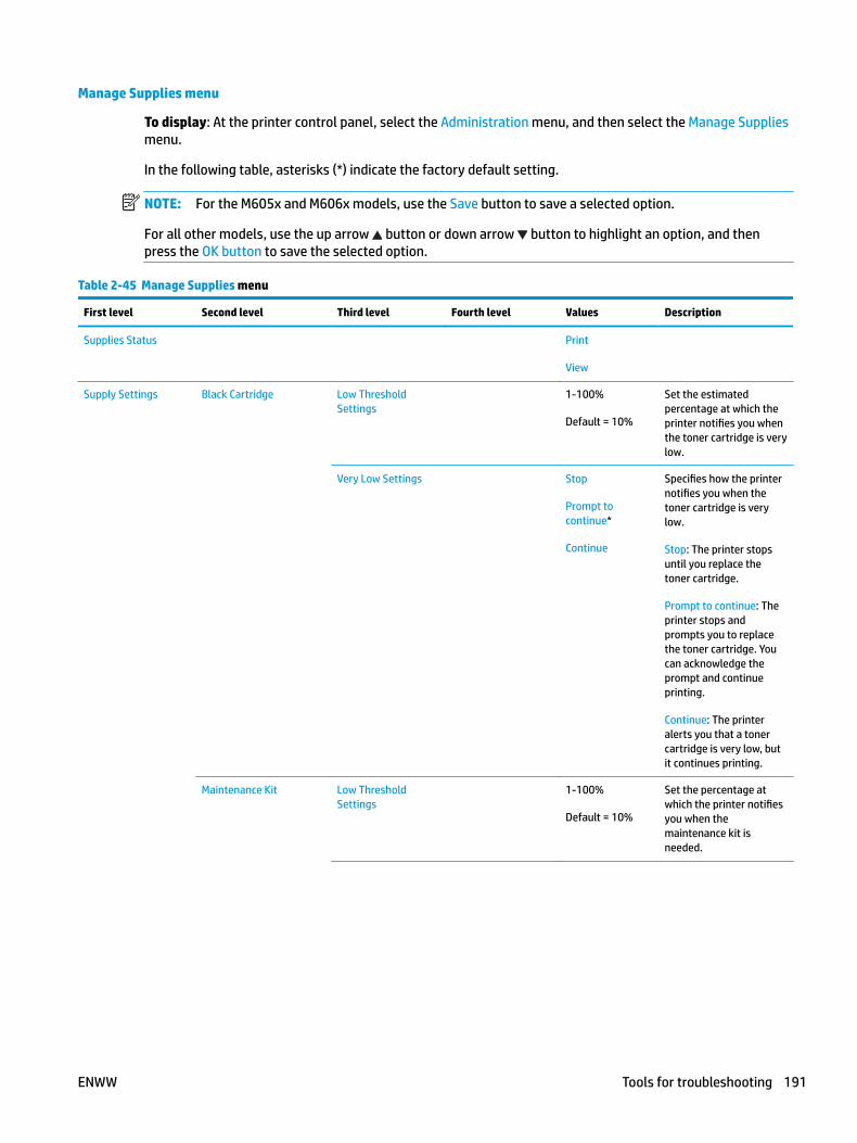
Manage Supplies menu
To display: At the printer control panel, select the Administration menu, and then select the Manage Supplies menu.
In the following table, asterisks (*) indicate the factory default setting.
NOTE: For the M605x and M606x models, use the Save button to save a selected option.
For all other models, use the up arrow button or down arrow button to highlight an option, and then press the OK button to save the selected option.
Table 2-45 Manage Supplies menu
First level Second level Third level Fourth level Values Description
Supplies Status Print
View
Supply Settings Black Cartridge Low Threshold Settings
1-100%
Default = 10%
Set the estimated percentage at which the printer notifies you when the toner cartridge is very low.
Very Low Settings Stop
Prompt to continue*
Continue
Specifies how the printer notifies you when the toner cartridge is very low.
Stop: The printer stops until you replace the toner cartridge.
Prompt to continue: The printer stops and prompts you to replace the toner cartridge. You can acknowledge the prompt and continue printing.
Continue: The printer alerts you that a toner cartridge is very low, but it continues printing.
Maintenance Kit Low Threshold Settings
1-100%
Default = 10%
Set the percentage at which the printer notifies you when the maintenance kit is needed.
ENWW Tools for troubleshooting 191
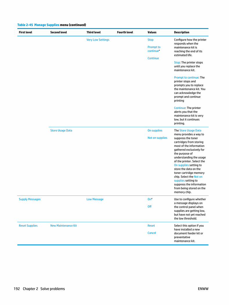
Table 2-45 Manage Supplies menu (continued)
First level Second level Third level Fourth level Values Description
Very Low Settings Stop
Prompt to continue*
Continue
Configure how the printer responds when the maintenance kit is reaching the end of its estimated life.
Stop: The printer stops until you replace the maintenance kit.
Prompt to continue: The printer stops and prompts you to replace the maintenance kit. You can acknowledge the prompt and continue printing
Continue: The printer alerts you that the maintenance kit is very low, but it continues printing.
Store Usage Data On supplies
Not on supplies
The Store Usage Data menu provides a way to suppress the toner cartridges from storing most of the information gathered exclusively for the purpose of understanding the usage of the printer. Select the On supplies setting to store the data on the toner cartridge memory chip. Select the Not on supplies setting to suppress the information from being stored on the memory chip.
Supply Messages Low Message On*
Off
Use to configure whether a message displays on the control panel when supplies are getting low, but have not yet reached the low threshold.
Reset Supplies New Maintenance Kit Reset
Cancel
Select this option if you have installed a new document feeder kit or preventative maintenance kit.
192 Chapter 2 Solve problems ENWW
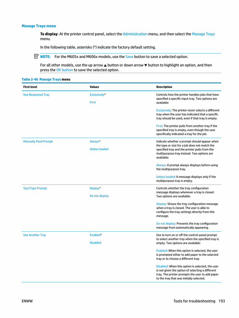
Manage Trays menu
To display: At the printer control panel, select the Administration menu, and then select the Manage Trays menu.
In the following table, asterisks (*) indicate the factory default setting.
NOTE: For the M605x and M606x models, use the Save button to save a selected option.
For all other models, use the up arrow button or down arrow button to highlight an option, and then press the OK button to save the selected option.
Table 2-46 Manage Trays menu
First level Values Description
Use Requested Tray Exclusively*
First
Controls how the printer handles jobs that have specified a specific input tray. Two options are available:
Exclusively: The printer never selects a different tray when the user has indicated that a specific tray should be used, even if that tray is empty.
First: The printer pulls from another tray if the specified tray is empty, even though the user specifically indicated a tray for the job.
Manually Feed Prompt Always*
Unless loaded
Indicate whether a prompt should appear when the type or size for a job does not match the specified tray and the printer pulls from the multipurpose tray instead. Two options are available:
Always: A prompt always displays before using the multipurpose tray.
Unless loaded: A message displays only if the multipurpose tray is empty.
Size/Type Prompt Display*
Do not display
Controls whether the tray configuration message displays whenever a tray is closed. Two options are available:
Display: Shows the tray configuration message when a tray is closed. The user is able to configure the tray settings directly from this message.
Do not display: Prevents the tray configuration message from automatically appearing.
Use Another Tray Enabled*
Disabled
Use to turn on or off the control-panel prompt to select another tray when the specified tray is empty. Two options are available:
Enabled: When this option is selected, the user is prompted either to add paper to the selected tray or to choose a different tray.
Disabled: When this option is selected, the user is not given the option of selecting a different tray. The printer prompts the user to add paper to the tray that was initially selected.
ENWW Tools for troubleshooting 193
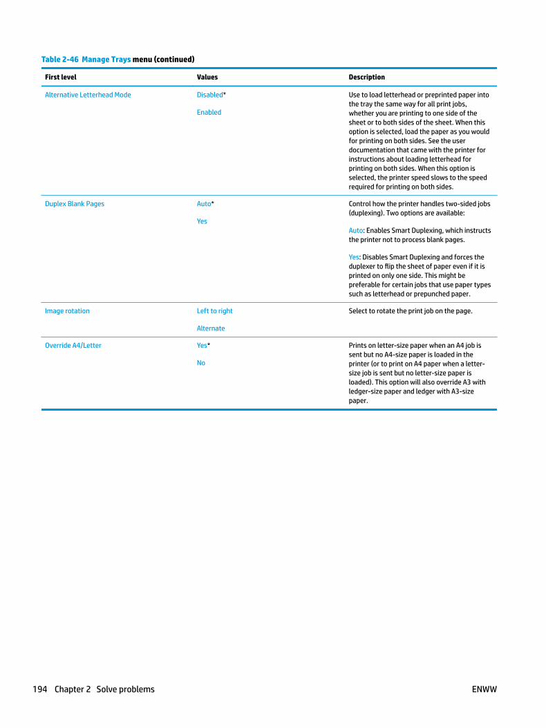
Table 2-46 Manage Trays menu (continued)
First level Values Description
Alternative Letterhead Mode Disabled*
Enabled
Use to load letterhead or preprinted paper into the tray the same way for all print jobs, whether you are printing to one side of the sheet or to both sides of the sheet. When this option is selected, load the paper as you would for printing on both sides. See the user documentation that came with the printer for instructions about loading letterhead for printing on both sides. When this option is selected, the printer speed slows to the speed required for printing on both sides.
Duplex Blank Pages Auto*
Yes
Control how the printer handles two-sided jobs (duplexing). Two options are available:
Auto: Enables Smart Duplexing, which instructs the printer not to process blank pages.
Yes: Disables Smart Duplexing and forces the duplexer to flip the sheet of paper even if it is printed on only one side. This might be preferable for certain jobs that use paper types such as letterhead or prepunched paper.
Image rotation Left to right
Alternate
Select to rotate the print job on the page.
Override A4/Letter Yes*
No
Prints on letter-size paper when an A4 job is sent but no A4-size paper is loaded in the printer (or to print on A4 paper when a letter-size job is sent but no letter-size paper is loaded). This option will also override A3 with ledger-size paper and ledger with A3-size paper.
194 Chapter 2 Solve problems ENWW
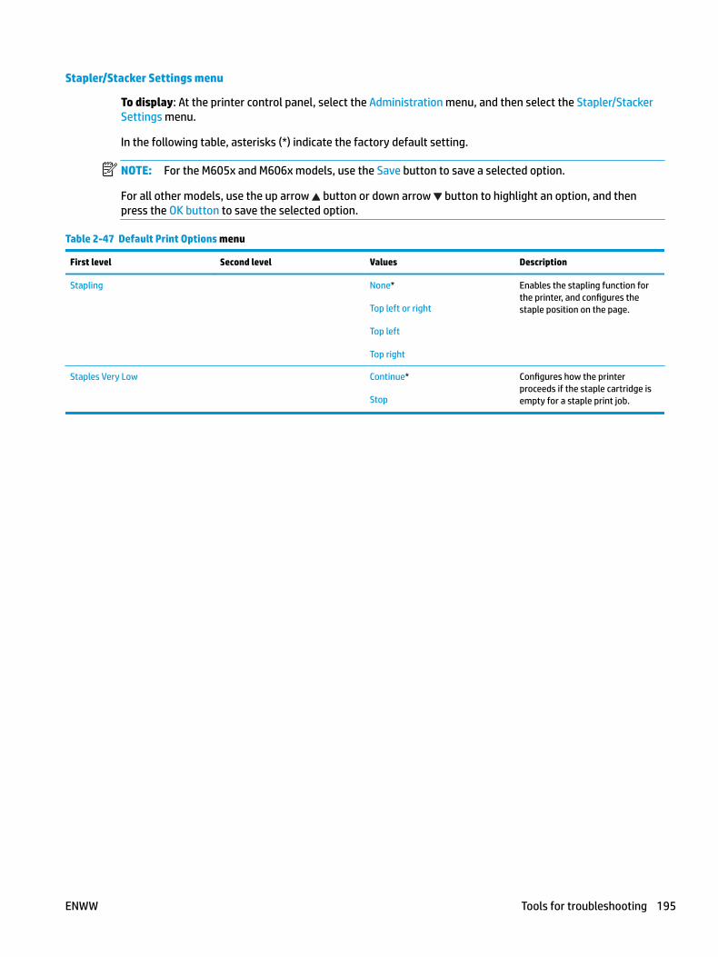
Stapler/Stacker Settings menu
To display: At the printer control panel, select the Administration menu, and then select the Stapler/Stacker Settings menu.
In the following table, asterisks (*) indicate the factory default setting.
NOTE: For the M605x and M606x models, use the Save button to save a selected option.
For all other models, use the up arrow button or down arrow button to highlight an option, and then press the OK button to save the selected option.
Table 2-47 Default Print Options menu
First level Second level Values Description
Stapling None*
Top left or right
Top left
Top right
Enables the stapling function for the printer, and configures the staple position on the page.
Staples Very Low Continue*
Stop
Configures how the printer proceeds if the staple cartridge is empty for a staple print job.
ENWW Tools for troubleshooting 195

Network Settings menu
To display: At the printer control panel, select the Administration menu, and then select the Network Settings menu.
In the following table, asterisks (*) indicate the factory default setting.
NOTE: For the M605x and M606x models, use the Save button to save a selected option.
For all other models, use the up arrow button or down arrow button to highlight an option, and then press the OK button to save the selected option.
Table 2-48 Network Settings menu
First level Values Description
IO Timeout Range: 5 – 300 sec
Default = 15
Use to set the I/O timeout period in seconds. I/O timeout refers to the elapsed time before a print job fails. If the stream of data that the printer receives for a print job gets interrupted, this setting indicates how long the printer will wait before it reports that the job has failed.
Embedded Jetdirect Menu See Table 2-49 Embedded Jetdirect Menu on page 196 for details. These menus have the same structure. If an additional HP Jetdirect network card is installed in the EIO slot, then both menus are available.
Table 2-49 Embedded Jetdirect Menu
First level Second level Third level Fourth level Values Description
Information Print Sec Report Yes
No*
Yes: Prints a page that contains the current security settings on the HP Jetdirect print server.
No: A security settings page is not printed.
TCP/IP Enable On*
Off
On: Enable the TCP/IP protocol.
Off: Disable the TCP/IP protocol.
Host Name Use the arrow buttons to edit the host name.
NPIXXXXXX*
An alphanumeric string, up to 32 characters, used to identify the printer. This name is listed on the HP Jetdirect configuration page. The default host name is NPIxxxxxx, where xxxxxx is the last six digits of the LAN hardware (MAC) address.
196 Chapter 2 Solve problems ENWW

Table 2-49 Embedded Jetdirect Menu (continued)
First level Second level Third level Fourth level Values Description
IPV4 Settings Config Method Bootp
DHCP*
Auto IP
Manual
Specifies the method that TCP/IPv4 parameters will be configured on the HP Jetdirect print server.
Bootp (Bootstrap Protocol): Use for automatic configuration from a BootP server.
DHCP (Dynamic Host Configuration Protocol): Use for automatic configuration from a DHCPv4 server. If selected and a DHCP lease exists, the DHCP Release menu and the DHCP Renew menu are available to set DHCP lease options.
Auto IP: Use for automatic link-local IPv4 addressing. An address in the form 169.254.x.x is assigned automatically.
If you set this option to the Manual setting, use the Manual Settings menu to configure TCP/IPv4 parameters.
Manual Settings
NOTE: This menu is available only if you select the Manual option under the Config Method menu.
IP Address Enter the address. (Available only if the Config Method option is set to the Manual option.) Configure parameters directly from the printer control panel:
Subnet Mask Enter the address.
Default Gateway Enter the address.
ENWW Tools for troubleshooting 197
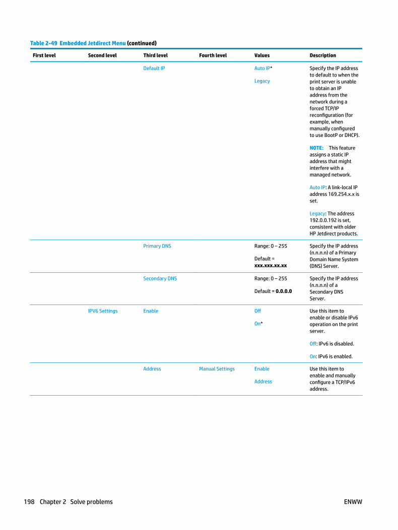
Table 2-49 Embedded Jetdirect Menu (continued)
First level Second level Third level Fourth level Values Description
Default IP Auto IP*
Legacy
Specify the IP address to default to when the print server is unable to obtain an IP address from the network during a forced TCP/IP reconfiguration (for example, when manually configured to use BootP or DHCP).
NOTE: This feature assigns a static IP address that might interfere with a managed network.
Auto IP: A link-local IP address 169.254.x.x is set.
Legacy: The address 192.0.0.192 is set, consistent with older HP Jetdirect products.
Primary DNS Range: 0 – 255
Default = xxx.xxx.xx.xx
Specify the IP address (n.n.n.n) of a Primary Domain Name System (DNS) Server.
Secondary DNS Range: 0 – 255
Default = 0.0.0.0
Specify the IP address (n.n.n.n) of a Secondary DNS Server.
IPV6 Settings Enable Off
On*
Use this item to enable or disable IPv6 operation on the print server.
Off: IPv6 is disabled.
On: IPv6 is enabled.
Address Manual Settings Enable
Address
Use this item to enable and manually configure a TCP/IPv6 address.
198 Chapter 2 Solve problems ENWW
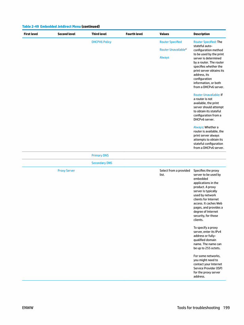
Table 2-49 Embedded Jetdirect Menu (continued)
First level Second level Third level Fourth level Values Description
DHCPV6 Policy Router Specified
Router Unavailable*
Always
Router Specified: The stateful auto-configuration method to be used by the print server is determined by a router. The router specifies whether the print server obtains its address, its configuration information, or both from a DHCPv6 server.
Router Unavailable: If a router is not available, the print server should attempt to obtain its stateful configuration from a DHCPv6 server.
Always: Whether a router is available, the print server always attempts to obtain its stateful configuration from a DHCPv6 server.
Primary DNS
Secondary DNS
Proxy Server Select from a provided list.
Specifies the proxy server to be used by embedded applications in the product. A proxy server is typically used by network clients for Internet access. It caches Web pages, and provides a degree of Internet security, for those clients.
To specify a proxy server, enter its IPv4 address or fully-qualified domain name. The name can be up to 255 octets.
For some networks, you might need to contact your Internet Service Provider (ISP) for the proxy server address.
ENWW Tools for troubleshooting 199
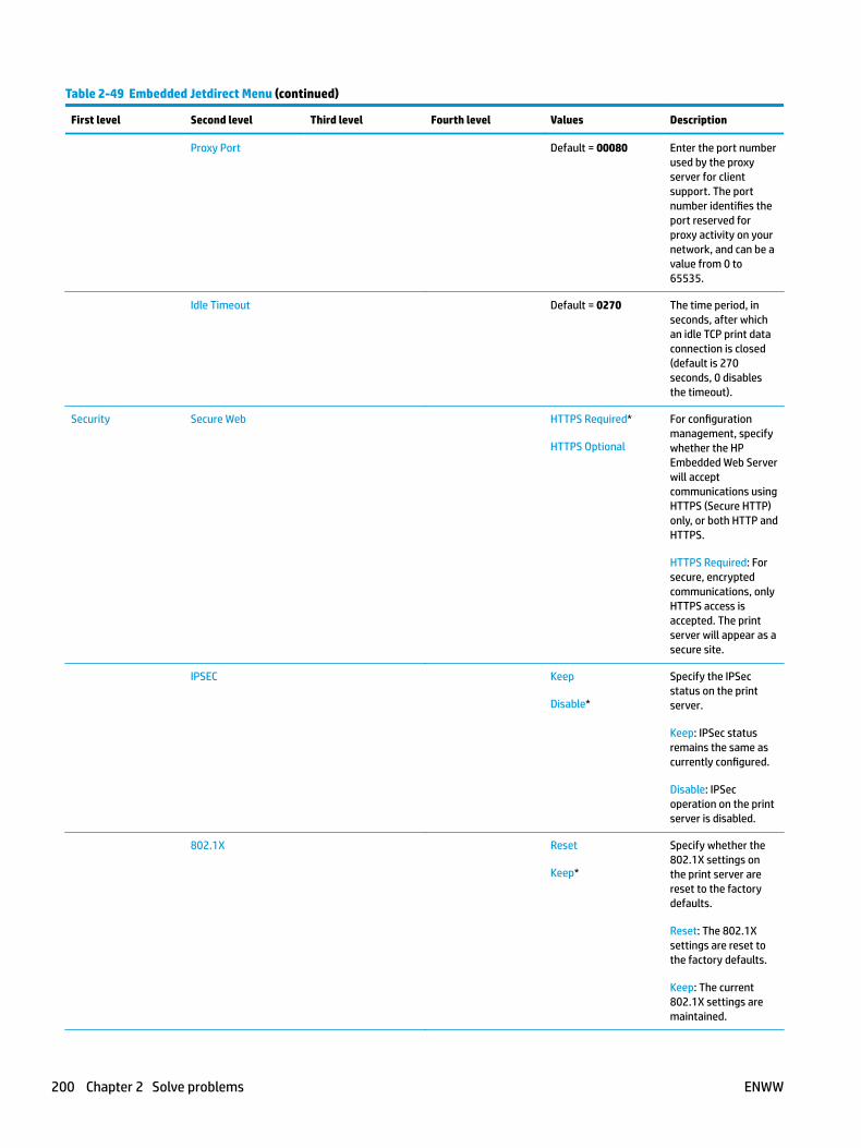
Table 2-49 Embedded Jetdirect Menu (continued)
First level Second level Third level Fourth level Values Description
Proxy Port Default = 00080 Enter the port number used by the proxy server for client support. The port number identifies the port reserved for proxy activity on your network, and can be a value from 0 to 65535.
Idle Timeout Default = 0270 The time period, in seconds, after which an idle TCP print data connection is closed (default is 270 seconds, 0 disables the timeout).
Security Secure Web HTTPS Required*
HTTPS Optional
For configuration management, specify whether the HP Embedded Web Server will accept communications using HTTPS (Secure HTTP) only, or both HTTP and HTTPS.
HTTPS Required: For secure, encrypted communications, only HTTPS access is accepted. The print server will appear as a secure site.
IPSEC Keep
Disable*
Specify the IPSec status on the print server.
Keep: IPSec status remains the same as currently configured.
Disable: IPSec operation on the print server is disabled.
802.1X Reset
Keep*
Specify whether the 802.1X settings on the print server are reset to the factory defaults.
Reset: The 802.1X settings are reset to the factory defaults.
Keep: The current 802.1X settings are maintained.
200 Chapter 2 Solve problems ENWW
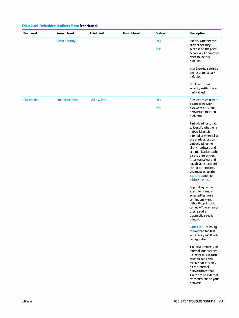
Table 2-49 Embedded Jetdirect Menu (continued)
First level Second level Third level Fourth level Values Description
Reset Security Yes
No*
Specify whether the current security settings on the print server will be saved or reset to factory defaults.
Yes: Security settings are reset to factory defaults.
No: The current security settings are maintained.
Diagnostics Embedded Tests LAN HW Test Yes
No*
Provides tests to help diagnose network hardware or TCP/IP network connection problems.
Embedded tests help to identify whether a network fault is internal or external to the product. Use an embedded test to check hardware and communication paths on the print server. After you select and enable a test and set the execution time, you must select the Execute option to initiate the test.
Depending on the execution time, a selected test runs continuously until either the printer is turned off, or an error occurs and a diagnostic page is printed.
CAUTION: Running this embedded test will erase your TCP/IP configuration.
This test performs an internal loopback test. An internal loopback test will send and receive packets only on the internal network hardware. There are no external transmissions on your network.
ENWW Tools for troubleshooting 201

Table 2-49 Embedded Jetdirect Menu (continued)
First level Second level Third level Fourth level Values Description
HTTP Test Yes
No*
This test checks operation of HTTP by retrieving predefined pages from the printer, and tests the HP Embedded Web Server.
Select the Yes option to choose this test, or the No option to not choose it.
SNMP Test Yes
No*
This test checks operation of SNMP communications by accessing predefined SNMP objects on the printer.
Select the Yes option to choose this test, or the No option to not choose it.
Data Path Test Yes
No*
This test helps to identify data path and corruption problems on an HP postscript level 3 emulation printer. It sends a predefined PS file to the printer, However, the test is paperless; the file will not print.
Select the Yes option to choose this test, or the No option to not choose it.
Select All Tests Yes
No*
Use this item to select all available embedded tests.
Select the Yes option to choose all tests. Select the No option to select individual tests.
202 Chapter 2 Solve problems ENWW
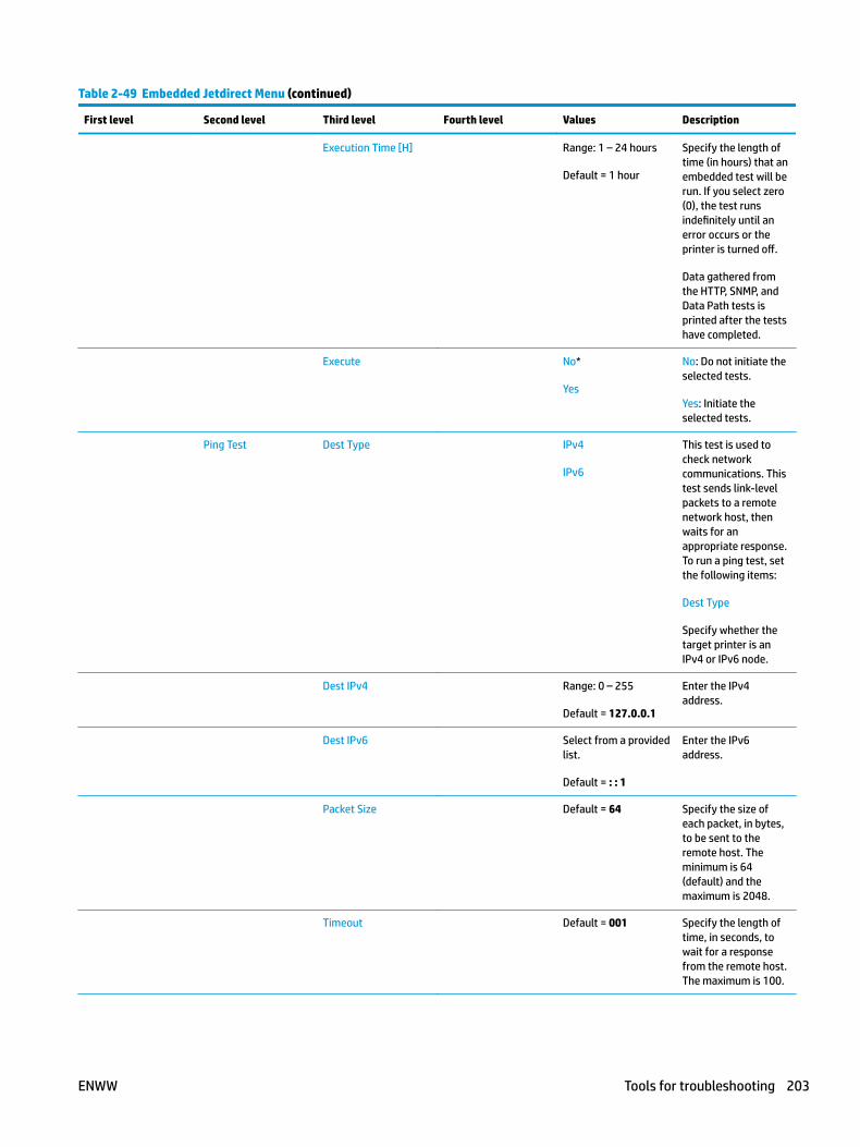
Table 2-49 Embedded Jetdirect Menu (continued)
First level Second level Third level Fourth level Values Description
Execution Time [H] Range: 1 – 24 hours
Default = 1 hour
Specify the length of time (in hours) that an embedded test will be run. If you select zero (0), the test runs indefinitely until an error occurs or the printer is turned off.
Data gathered from the HTTP, SNMP, and Data Path tests is printed after the tests have completed.
Execute No*
Yes
No: Do not initiate the selected tests.
Yes: Initiate the selected tests.
Ping Test Dest Type IPv4
IPv6
This test is used to check network communications. This test sends link-level packets to a remote network host, then waits for an appropriate response. To run a ping test, set the following items:
Dest Type
Specify whether the target printer is an IPv4 or IPv6 node.
Dest IPv4 Range: 0 – 255
Default = 127.0.0.1
Enter the IPv4 address.
Dest IPv6 Select from a provided list.
Default = : : 1
Enter the IPv6 address.
Packet Size Default = 64 Specify the size of each packet, in bytes, to be sent to the remote host. The minimum is 64 (default) and the maximum is 2048.
Timeout Default = 001 Specify the length of time, in seconds, to wait for a response from the remote host. The maximum is 100.
ENWW Tools for troubleshooting 203
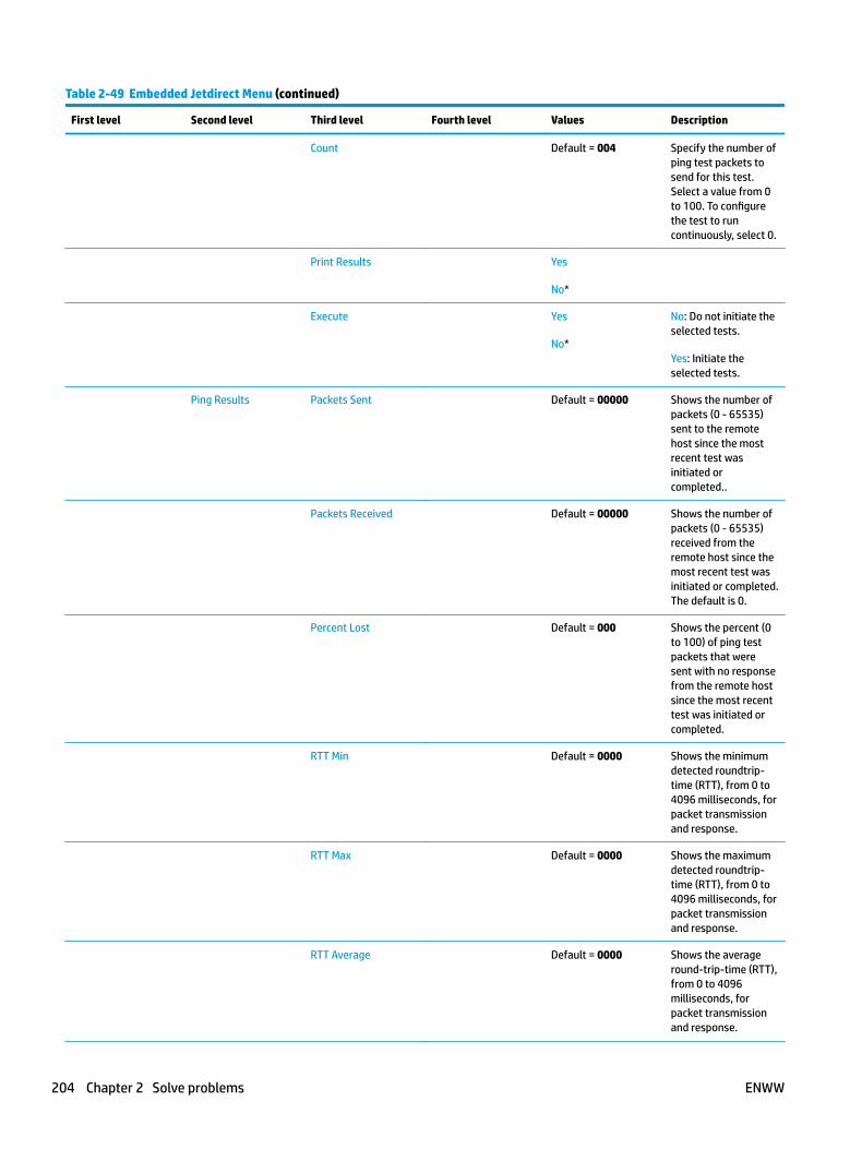
Table 2-49 Embedded Jetdirect Menu (continued)
First level Second level Third level Fourth level Values Description
Count Default = 004 Specify the number of ping test packets to send for this test. Select a value from 0 to 100. To configure the test to run continuously, select 0.
Print Results Yes
No*
Execute Yes
No*
No: Do not initiate the selected tests.
Yes: Initiate the selected tests.
Ping Results Packets Sent Default = 00000 Shows the number of packets (0 - 65535) sent to the remote host since the most recent test was initiated or completed..
Packets Received Default = 00000 Shows the number of packets (0 - 65535) received from the remote host since the most recent test was initiated or completed. The default is 0.
Percent Lost Default = 000 Shows the percent (0 to 100) of ping test packets that were sent with no response from the remote host since the most recent test was initiated or completed.
RTT Min Default = 0000 Shows the minimum detected roundtrip-time (RTT), from 0 to 4096 milliseconds, for packet transmission and response.
RTT Max Default = 0000 Shows the maximum detected roundtrip-time (RTT), from 0 to 4096 milliseconds, for packet transmission and response.
RTT Average Default = 0000 Shows the average round-trip-time (RTT), from 0 to 4096 milliseconds, for packet transmission and response.
204 Chapter 2 Solve problems ENWW
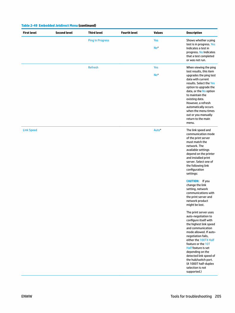
Table 2-49 Embedded Jetdirect Menu (continued)
First level Second level Third level Fourth level Values Description
Ping In Progress Yes
No*
Shows whether a ping test is in progress. Yes Indicates a test in progress. No Indicates that a test completed or was not run.
Refresh Yes
No*
When viewing the ping test results, this item upgrades the ping test data with current results. Select the Yes option to upgrade the data, or the No option to maintain the existing data. However, a refresh automatically occurs when the menu times out or you manually return to the main menu.
Link Speed Auto* The link speed and communication mode of the print server must match the network. The available settings depend on the printer and installed print server. Select one of the following link configuration settings:
CAUTION: If you change the link setting, network communications with the print server and network product might be lost.
The print server uses auto-negotiation to configure itself with the highest link speed and communication mode allowed. If auto-negotiation fails, either the 100TX Half feature or the 10T Half feature is set depending on the detected link speed of the hub/switch port. (A 1000T half-duplex selection is not supported.)
ENWW Tools for troubleshooting 205
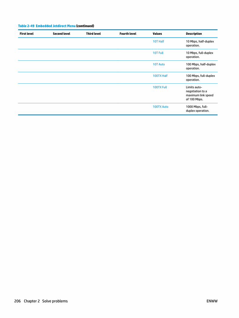
Table 2-49 Embedded Jetdirect Menu (continued)
First level Second level Third level Fourth level Values Description
10T Half 10 Mbps, half-duplex operation.
10T Full 10 Mbps, full-duplex operation.
10T Auto 100 Mbps, half-duplex operation.
100TX Half 100 Mbps, full-duplex operation.
100TX Full Limits auto-negotiation to a maximum link speed of 100 Mbps.
100TX Auto 1000 Mbps, full-duplex operation.
206 Chapter 2 Solve problems ENWW
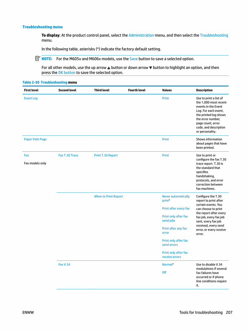
Troubleshooting menu
To display: At the product control panel, select the Administration menu, and then select the Troubleshooting menu.
In the following table, asterisks (*) indicate the factory default setting.
NOTE: For the M605x and M606x models, use the Save button to save a selected option.
For all other models, use the up arrow button or down arrow button to highlight an option, and then press the OK button to save the selected option.
Table 2-50 Troubleshooting menu
First level Second level Third level Fourth level Values Description
Event Log Print Use to print a list of the 1,000 most recent events in the Event Log. For each event, the printed log shows the error number, page count, error code, and description or personality.
Paper Path Page Print Shows information about pages that have been printed.
Fax
Fax models only
Fax T.30 Trace Print T.30 Report Print Use to print or configure the fax T.30 trace report. T.30 is the standard that specifies handshaking, protocols, and error correction between fax machines.
When to Print Report Never automatically print*
Print after every fax
Print only after fax send jobs
Print after any fax error
Print only after fax send errors
Print only after fax receive errors
Configure the T.30 report to print after certain events. You can choose to print the report after every fax job, every fax job sent, every fax job received, every send error, or every receive error.
Fax V.34 Normal*
Off
Use to disable V.34 modulations if several fax failures have occurred or if phone line conditions require it.
ENWW Tools for troubleshooting 207
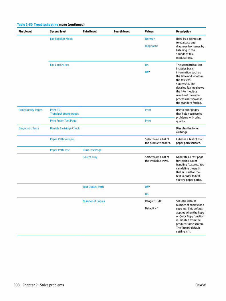
Table 2-50 Troubleshooting menu (continued)
First level Second level Third level Fourth level Values Description
Fax Speaker Mode Normal*
Diagnostic
Used by a technician to evaluate and diagnose fax issues by listening to the sounds of fax modulations.
Fax Log Entries On
Off*
The standard fax log includes basic information such as the time and whether the fax was successful. The detailed fax log shows the intermediate results of the redial process not shown in the standard fax log.
Print Quality Pages Print PQ Troubleshooting pages
Print Use to print pages that help you resolve problems with print quality.Print Fuser Test Page Print
Diagnostic Tests Disable Cartridge Check Disables the toner cartridge.
Paper Path Sensors Select from a list of the product sensors.
Initiates a test of the paper path sensors.
Paper Path Test Print Test Page
Source Tray Select from a list of the available trays.
Generates a test page for testing paper handling features. You can define the path that is used for the test in order to test specific paper paths.
Test Duplex Path Off*
On
Number of Copies Range: 1–500
Default = 1
Sets the default number of copies for a copy job. This default applies when the Copy or Quick Copy function is initiated from the product Home screen. The factory default setting is 1.
208 Chapter 2 Solve problems ENWW

Table 2-50 Troubleshooting menu (continued)
First level Second level Third level Fourth level Values Description
Manual Sensor Test Select from a list of available components.
Reset Sensors
Test the product sensors and switches for correct operation. Each sensor is displayed on the control-panel screen, along with its status. Manually trip each sensor and watch for it to change on the screen. Press the Stop button to abort the test.
Tray/Bin Manual Sensor Test
Select from a list of available components.
Reset Sensors
Test the sensors in the trays and bins for correct operation. Each sensor is displayed on the control-panel screen, along with its status. Manually trip each sensor and watch for it to change on the screen. Press the Stop button to abort the test.
Component Test Select from a list of available components.
Use to exercise individual parts independently to isolate noise, leaking, or other issues. To start the test, select one of the components. The test will run the number of times specified by the Repeat option. You might be prompted to remove parts from the product during the test. Press the Stop button to abort the test.
Retrieve Diagnostic Data
Create device data file
Create zipped debug information file
Include crash dump files
Clean up debug information
Send to E-mail
Export to USB
Create files that contain information about the product that can help identify the cause of problems.
Generate Debug Data Start
ENWW Tools for troubleshooting 209
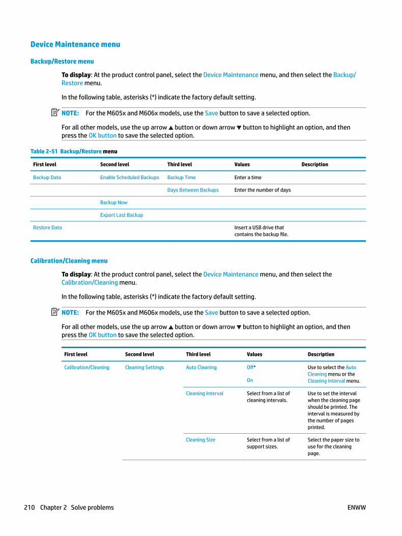
Device Maintenance menu
Backup/Restore menu
To display: At the product control panel, select the Device Maintenance menu, and then select the Backup/Restore menu.
In the following table, asterisks (*) indicate the factory default setting.
NOTE: For the M605x and M606x models, use the Save button to save a selected option.
For all other models, use the up arrow button or down arrow button to highlight an option, and then press the OK button to save the selected option.
Table 2-51 Backup/Restore menu
First level Second level Third level Values Description
Backup Data Enable Scheduled Backups Backup Time Enter a time
Days Between Backups Enter the number of days
Backup Now
Export Last Backup
Restore Data Insert a USB drive that contains the backup file.
Calibration/Cleaning menu
To display: At the product control panel, select the Device Maintenance menu, and then select the Calibration/Cleaning menu.
In the following table, asterisks (*) indicate the factory default setting.
NOTE: For the M605x and M606x models, use the Save button to save a selected option.
For all other models, use the up arrow button or down arrow button to highlight an option, and then press the OK button to save the selected option.
First level Second level Third level Values Description
Calibration/Cleaning Cleaning Settings Auto Cleaning Off*
On
Use to select the Auto Cleaning menu or the Cleaning Interval menu.
Cleaning Interval Select from a list of cleaning intervals.
Use to set the interval when the cleaning page should be printed. The interval is measured by the number of pages printed.
Cleaning Size Select from a list of support sizes.
Select the paper size to use for the cleaning page.
210 Chapter 2 Solve problems ENWW
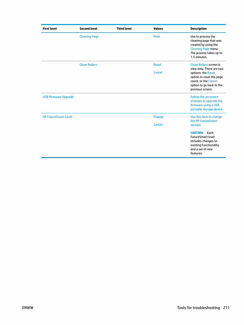
First level Second level Third level Values Description
Cleaning Page Print Use to process the cleaning page that was created by using the Cleaning Page menu. The process takes up to 1.5 minutes.
Clean Rollers Reset
Cancel
Clean Rollers screen is view only. There are two options: the Reset option to reset the page count, or the Cancel option to go back to the previous screen.
USB Firmware Upgrade Follow the on screen prompts to upgrade the firmware using a USB portable storage device.
HP FutureSmart Level Change
Cancel
Use this item to change the HP FutureSmart version.
CAUTION: Each FutureSmart level includes changes to existing functionality and a set of new features.
ENWW Tools for troubleshooting 211

USB Firmware Upgrade menu
To display: At the product control panel, select the Device Maintenance menu, and then select the USB Firmware Upgrade menu.
Insert a USB storage device with a firmware upgrade bundle into the USB port, and follow the on-screen instructions.
Service menu
To display: At the product control panel, select the Device Maintenance menu, and then select the Service menu.
The Service menu is locked and requires a PIN for access. This menu is intended for use by authorized service personnel. See the Service mode function section in the product troubleshooting manual.
212 Chapter 2 Solve problems ENWW
Control panel message document (CPMD)
Control-panel message types
The control-panel messages and event code entries indicate the current product status or situations that might require action.
NOTE: Event log errors do not appear on the control-panel display. Open the event log to view or print the event log errors.
A control-panel message displays temporarily and might require the user to acknowledge the message by touching the OK button to resume printing or by touching the Stop button to cancel the job. With certain messages, the job might not finish printing or the print quality might be affected. If the message is related to printing and the auto-continue feature is on, the product will attempt to resume printing after the message has appeared for 10 seconds without acknowledgement.
For some messages, restarting the product might fix the problem. If a critical error persists, the product might require service.
Control-panel messages and event log entries
NOTE: Some of the messages in the following sections only appear in the event log.
TIP: Some control-panel messages and event log entries refer to a specific product sensor or switch in the recommended action to solve the problem. See the diagrams in the clear jams section of the product troubleshooting manual for sensor and switch locations.
10.XX.YZ Error Messages
10.00.00 e-Label Memory Error
Description
The printer is unable to read the cartridge data.
This message indicates that the printer cannot read or write to the e-label of the toner cartridge.
This error can cause the supplies status feature to be disabled.
Recommended action
1. Remove, and then reinstall the indicated print cartridge.
2. If the error reappears, turn the power off, and then on.
3. Check the cartridge memory tag. If it is damaged, replace the cartridge.
4. If the error persists, replace the indicated print cartridge.
10.00.10 e-Label Missing Memory Error
Description
The printer is unable to detect the e-label.
This message indicates that the printer has determined that the e-label is missing.
This error can cause the supplies status feature to be disabled.
ENWW Tools for troubleshooting 213
Recommended action
1. Remove and the reinstall the indicated print cartridge.
2. If the message displays again, turn the printer off then on.
3. Check the cartridge memory tag. If it is damaged, replace the cartridge.
4. If the error persists, replace the indicated print cartridge.
10.00.15 Install <supply>
Description
The indicated supply has been removed or installed incorrectly.
10.00.15 (event code) Black Toner cartridge
Recommended action
Replace or install the indicated supply.
See the parts chapter in the service manual for the correct supply or kit part number.
10.00.33 Used Supply In Use
Description
A used supply is in use (end of life).
10.00.33 (event code) Black toner cartridge
Recommended action
No action necessary.
If you believe this is a genuine HP supply, go to www.hp.com/go/anticounterfeit.
Using a cartridge that is near its end-of-life can cause this event code.
10.00.34 Used supply in use
Description
The print cartridge is used.
10.00.34 (event code) Black toner cartridge
Recommended action
If you believe this is a genuine HP supply, go to www.hp.com/go/anticounterfeit.
NOTE: Removing a cartridge from one printer and then installing it in a different printer (for testing functionality) will cause this event code.
10.00.35 Incompatible supply in use
Description
An incompatible supply is in use.
214 Chapter 2 Solve problems ENWW
10.00.35 (event code) Black toner cartridge
Recommended action
Install the correct HP print cartridge for this printer.
NOTE: The toner cartridge is not compatible with the printer
10.00.40 Genuine HP supplies installed
Description
A genuine HP print cartridge has been installed.
10.00.40 (event code) Black toner cartridge
Recommended action
No action necessary.
10.00.41 Unsupported Supply in Use
Description
The installed toner cartridge is for a different printer.
10.00.41 (event code) Black toner cartridge
Recommended action
Remove the toner cartridge, and then install the correct cartridge for this printer.
See the parts chapter in the service manual for the correct cartridge part number.
10.00.60 Black cartridge low
Description
The black cartridge is low.
Recommended action
If print quality is no longer acceptable, replace the print cartridge.
TIP: Advise the customer that HP recommends that they have replacement supplies available to install when the print quality is no longer acceptable.
10.00.69 Black cartridge very low
Description
The black cartridge is very low.
Recommended action
If print quality is no longer acceptable, replace the print cartridge.
TIP: Advise the customer that HP recommends that they have replacement supplies available to install when the print quality is no longer acceptable.
ENWW Tools for troubleshooting 215
10.00.70 Printing past very low
Description
The printer indicates when a supply level is very low. The actual remaining toner cartridge life might vary.
You do not need to replace the toner cartridge at this time unless print quality is no longer acceptable. After an HP supply has reached the very low threshold, the HP premium protection warranty ends.
10.00.70 (event code) Black toner cartridge
Recommended action
If print quality is no longer acceptable, replace the toner cartridge.
See the parts chapter in the service manual for the correct cartridge part number. Advise the customer that HP recommends that they have replacement supplies available to install when the print quality is no longer acceptable.
10.00.91 Cartridge motor stall
Description
Cartridge motor stall.
Recommended action
Replace the print cartridge.
10.23.15 Install <supply>
Description
The indicated supply has been removed or installed incorrectly.
10.23.15 (event code) Fuser kit
Recommended action
Replace or install the indicated supply.
See the parts chapter in the service manual for the correct supply or kit part number.
10.23.35 Incompatible <supply>
Description
The indicated supply is not compatible with this printer.
10.23.35 (event code) Fuser kit
Recommended action
CAUTION: The fuser might be hot. Be careful when removing the fuser.
Install a supply that is designed for this printer.
See the parts chapter in the service manual for the correct supply part number.
216 Chapter 2 Solve problems ENWW

TIP: Advise the customer that HP recommends that they have replacement supplies available to install when the print quality is no longer acceptable.
10.23.50
Description
The fuser kit life was reset above the order threshold.
Recommended action
No action necessary.
10.23.51
Description
The fuser kit life was reset above the replace threshold.
Recommended action
No action necessary.
10.23.52
Description
The fuser kit life was reset above the reset threshold.
Recommended action
No action necessary.
10.23.60
Description
The printer indicates when fuser kit is very low. The actual remaining fuse kit life might vary.
You do not need to replace the fuser kit at this time unless print quality is no longer acceptable.
NOTE: After an HP supply has reached the very low threshold, the HP premium protection warranty ends.
Recommended action
If print quality is no longer acceptable, replace the fuser kit. See the parts chapter in the service manual for the fuser kit part number.
TIP: Advise the customer that HP recommends that they have replacement supplies available to install when the print quality is no longer acceptable.
10.23.70 printing past very low
Description
The printer indicates when the fuser kit is very low. The actual remaining fuse kit life might vary.
10.23.70 (event code) Fuser kit
ENWW Tools for troubleshooting 217
Recommended action
If print quality is no longer acceptable, replace the fuser kit. See the parts chapter in the service manual for the fuser kit part number.
TIP: Advise the customer that HP recommends that they have replacement supplies available to install when the print quality is no longer acceptable.
NOTE: After an HP supply has reached the very low threshold, the HP premium protection warranty ends.
10.26.15
Description
The printer indicates when the maintenance might need to be replaced.
Recommended action
If print quality is no longer acceptable, replace the maintenance kit. See the parts chapter in the service manual for the maintenance kit part number.
TIP: Advise the customer that HP recommends that they have replacement supplies available to install when the print quality is no longer acceptable.
10.26.50
Description
The maintenance kit was reset.
Recommended action
No action required.
10.26.60
Description
The printer indicates when the maintenance kit is very low. The actual remaining maintenance kit life might vary.
You do not need to replace the maintenance kit at this time unless print quality is no longer acceptable.
NOTE: After an HP supply has reached the very low threshold, the HP premium protection warranty ends.
Recommended action
If print quality is no longer acceptable, replace the maintenance kit. See the parts chapter in the service manual for the maintenance kit part number.
TIP: Advise the customer that HP recommends that they have replacement supplies available to install when the print quality is no longer acceptable.
218 Chapter 2 Solve problems ENWW
11.XX.YZ Error Messages
11.00.01 or 11.00.02 Internal clock error
Description
The printer real time clock has experienced an error.
01=dead clock
02=dead real time clock
Recommended action
1. Whenever the printer is turned off and then turned on again, set the time and date on the control panel.
2. If the error persists, remove and reinstall the formatter making sure it is seated properly.
3. Replace the formatter.
13.XX.YZ Error Messages
13.00.00
Description
Generic jam event code.
Recommended action
Check the printer for a jam. See the clear jams section in the service manual.
13.00.EE
Description
Unknown door open.
Recommended action
Make sure that all of the doors and covers are closed.
13.A2.D2
Description
Tray 2 media feed jam.
This jam occurs when the media does not reach the Tray 2 pre-feed sensor (PS102) in the designated amount of time after the start of media pickup from Tray 2.
This is a no-pick jam from tray 2.
Recommended action
1. Open Tray 2, remove any jammed paper, and then close the tray.
2. Open and close the upper TOP cover to allow the printer to attempt to clear the jam.
ENWW Tools for troubleshooting 219

3. Remove the paper from the tray and check that the paper tray size guides are properly set and that the tray is not over filled with paper.
Figure 2-90 Paper Tray guides
Figure 2-91 Paper Tray overfill guide
4. Make sure that the Tray 2 pickup, feed, and separation roller are installed correctly and show no damage or wear.
5. Clean or replace the pickup/feed rollers as needed.
6. Verify that the media in use meets the printers specifications.
7. Open the following menus:
220 Chapter 2 Solve problems ENWW

● Administration
● Troubleshooting
● Diagnostic Tests
8. Run the Tray 2 pickup/feed motor drive test to verify that the feed motor is functioning correctly. If it is not, replace the pickup assembly.
9. Test PS102 using the Tray/Bin Manual sensor test to verify that the sensor is functioning correctly.
10. If the error persists, replace the paper pickup assembly.
11. If PS102 is defective elevate the issue to HP for possible printer replacement.
13.A2.Dx
Description
Optional Tray media feed jam.
This jam occurs when the media does not reach the Tray pre-feed sensor (PS1603 for trays 3–5) (PS1704 for tray 6) in the designated amount of time after the start of media pickup from Tray.
This is a no-pick jam from the specified tray.
● 13.A2.D3
Multi-Feed jam is detected when printing from Tray 3.
● 13.A2.D4
Multi-Feed jam is detected when printing from Tray 4.
● 13.A2.D5
Multi-Feed jam is detected when printing from Tray 5.
● 13.A2.D6
Multi-Feed jam is detected when printing from Tray 6.
Recommended action
1. Open the Tray, remove any jammed paper, and then close the tray.
2. Open and close the upper TOP cover to allow the printer to attempt to clear the jam.
ENWW Tools for troubleshooting 221

3. Remove the paper from the tray and check that the paper tray size guides are properly set and that the tray is not over filled with paper.
Figure 2-92 Paper Tray guides
Figure 2-93 Paper Tray overfill guide
4. Make sure that the Tray pickup, feed, and separation roller are installed correctly and show no damage or wear.
5. Clean or replace the pickup/feed rollers as needed.
6. Verify that the media in use meets the printers specifications.
7. Open the following menus:
222 Chapter 2 Solve problems ENWW
● Administration
● Troubleshooting
● Diagnostic Tests
8. Run the Tray pickup/feed motor drive test to verify that the feed motor is functioning correctly. If it is not, replace the pickup assembly.
9. Test PS1603 or PS1704 using the Tray/Bin Manual sensor test to verify that the sensor is functioning correctly.
10. If the error persists, replace the paper pickup assembly.
11. If PS1603 or PS1704 is defective, replace the appropriate paper input unit that houses the sensor.
13.A2.FF
Description
Residual Media Jam in Tray 2.
This jam occurs when residual media is detected at the Tray 2 feed sensor (PS102).
Recommended action
1. Open Tray 2, remove any jammed paper, and then close the tray.
2. Open and close the upper right door to allow the printer to attempt to clear the jam.
ENWW Tools for troubleshooting 223
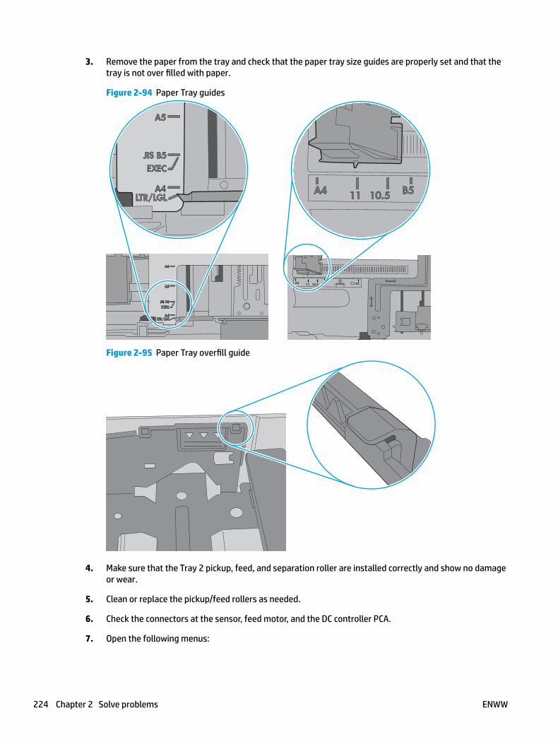
3. Remove the paper from the tray and check that the paper tray size guides are properly set and that the tray is not over filled with paper.
Figure 2-94 Paper Tray guides
Figure 2-95 Paper Tray overfill guide
4. Make sure that the Tray 2 pickup, feed, and separation roller are installed correctly and show no damage or wear.
5. Clean or replace the pickup/feed rollers as needed.
6. Check the connectors at the sensor, feed motor, and the DC controller PCA.
7. Open the following menus:
224 Chapter 2 Solve problems ENWW

● Administration
● Troubleshooting
● Diagnostic Tests
8. Test PS102 using the Tray/Bin Manual sensor test to verify that the sensors are functioning correctly.
9. Run the Tray 2 pickup/feed motor drive test to verify that the feed motor is functioning correctly (listen for the motor to activate). If it is not, replace the pickup assembly.
10. If the error persists, replace the paper pickup assembly.
13.A3.FF
Description
Residual Media Jam in Tray 3.
This jam occurs when residual media is detected at the Tray 3 feed sensor (PS102).
Recommended action
1. Open Tray 3, remove any jammed paper, and then close the tray.
2. Open and close the upper right door to allow the printer to attempt to clear the jam.
ENWW Tools for troubleshooting 225

3. Remove the paper from the tray and check that the paper tray size guides are properly set and that the tray is not over filled with paper.
Figure 2-96 Paper Tray guides
Figure 2-97 Paper Tray overfill guide
4. Make sure that the Tray 3 pickup, feed, and separation roller are installed correctly and show no damage or wear.
5. Clean or replace the pickup/feed rollers as needed.
6. Check the connectors at the sensor, feed motor, and the DC controller PCA.
7. Open the following menus:
226 Chapter 2 Solve problems ENWW
● Administration
● Troubleshooting
● Diagnostic Tests
8. Test PS102 using the Tray/Bin Manual sensor test to verify that the sensors are functioning correctly.
9. Run the Tray 3 pickup/feed motor drive test to verify that the feed motor is functioning correctly (listen for the motor to activate). If it is not, replace the pickup assembly.
10. If the error persists, replace the paper pickup assembly.
13.B2.Az Jam in top cover
Description
Media STAY jam in top cover at image area.
Paper present at PS103 after specified time limit passed
● 13.B2.A1
This jam occurs when the media is present longer than "the expected media length plus 50mm" or more is detected at the Registration sensor (PS103) when printing from the Tray 1.
● 13.B2.A2
This jam occurs when the media is present longer than" the expected media length plus 50mm" or more is detected at the Registration sensor (PS103) when printing from the Tray 2.
● 13.B2.A3
This jam occurs when the media is present longer than "the expected media length plus 50mm" or more is detected at the Registration sensor (PS103) when printing from the Tray 3.
● 13.B2.A4
This jam occurs when the media is present longer than "the expected media length plus 50mm" or more is detected at the Registration sensor PS103) when printing from the Tray 4.
● 13.B2.AD
This jam occurs when the media is present longer than "the expected media length plus 50mm" or more is detected at the Registration sensor (PS103) when printing from the Duplexer.
Recommended action
1. Open top cover and check for media jammed in feed area.
2. Test the top of page sensor (PS103) to ensure that it moves freely.
3. Check under toner cartridge at transfer area, make sure everything is properly seated and there are no damaged parts.
4. Ensure the type and quality of the media that you are using meet HP specifications.
5. Open the following menus:
ENWW Tools for troubleshooting 227

● Administration
● Troubleshooting
● Diagnostic Tests
6. Test Registration Sensor Test (TOP sensor) (PS103) using the Tray/Bin manual sensor test to verify that the sensor is functioning correctly.
7. Test the Media Width sensors PS106 and PS108 if defective replace.
8. If sensor functioning properly, run a few pages to check where the leading edge of the paper actually stops.
9. If any test shows defective part replace the appropriate assembly.
13.B2.Dz Jam in top cover
Description
Media delay jam in top cover at image area.
Paper did not reach PS103 in specified time.
● 13.B2.D1
Media did not reach the Registration sensor in the designated amount of time printing from Tray 1.
● 13.B2.D2
Media did not reach the Registration sensor in the designated amount of time printing from Tray 2.
● 13.B2.D3
Media did not reach the Registration sensor in the designated amount of time printing from Tray 3.
● 13.B2.D4
Media did not reach the Registration sensor in the designated amount of time printing from Tray 4.
● 13.B2.DD
Media did not reach the Registration sensor in the designated amount of time printing duplexed.
Recommended action
1. Open top cover and check for media jammed in feed area.
2. Check for worn out Tray Feed and Separation rollers, replace if found worn out.
3. Test the top of page sensor (PS103).
4. Check registration assembly.
5. Replace parts as determined by tests.
13.B2.E2 Jam in top cover
Description
Media jam in top cover at image area due to door open.
228 Chapter 2 Solve problems ENWW
Recommended action
1. Make sure all doors and covers are closed and re-send job.
2. If all doors are closed and message still persists, Test SW101 Door open detection switch using the diagnostic tests.
If test fails replace the switch.
13.B2.FF Jam in top cover
Description
Media residual jam in top cover at image area.
Paper present at PS103 at power on or after clearing jam.
Recommended action
1. Open top cover and check for media jammed in feed area.
2. Check under toner cartridge at transfer area, make sure everything is properly seated.
3. Test the top of page sensor (PS103).
13.B9.Az Fuser jam
Description
Fuser delivery stay.
Media stay jam at fuser area.
Paper present at PS700 after specified time limit.
This jam code may be caused by;
An accordion jam at the fuser exit, something blocking the media before the output rollers. The output bin rollers not turning, there is very little distance from the fuser exit and the output bin.
A sticky fuser exit flag, if it stuck or even delayed momentarily in the activated position.
● 13.B9.A1
Multi-Feed jam is detected when printing from Tray 1.
● 13.B9.A2
Multi-Feed jam is detected when printing from Tray 2.
● 13.B9.A3
Multi-Feed jam is detected when printing from Tray 3.
● 13.B9.A4
Multi-Feed jam is detected when printing from Tray 4.
● 13.B9.AD
Multi-Feed jam is detected when printing from the Duplexer.
ENWW Tools for troubleshooting 229
Recommended action
CAUTION: Be careful the fuser is HOT, allow it cool if you need to remove debris from in and around the pressure heating components.
1. Open the top and rear covers and then clear any jammed paper.
2. Ensure sure that the paper meets HP printer specifications.
3. Check Fuser delivery sensor for proper functionality and movement.
4. verify there is no debris from a previous jam stuck in the fuser or rollers leading into or out of the fuser.
5. Confirm the output bin rollers are turning.
6. Perform Manuel Sensor Test and check PS 700 Fuser delivery sensor. If found faulty then replace the Fuser assembly.
7. Perform Manuel Sensor Test and Replace the fuser assembly.
13.B9.Bz Fuser jam
Description
Multi-feed jam in fuser.
This jam occurs when a near complete overlap (less than 5 to 15 mm of non-overlap) multi-feed jam is detected.
● 13.B9.B1
Multi-Feed jam is detected when printing from Tray 1.
● 13.B9.B2
Multi-Feed jam is detected when printing from Tray 2.
● 13.B9.B3
Multi-Feed jam is detected when printing from Tray 3.
● 13.B9.B4
Multi-Feed jam is detected when printing from Tray 4.
● 13.B9.BD
Multi-Feed jam is detected when printing from the Duplexer.
Recommended action
1. Open the top and rear covers and then clear any jammed paper.
2. Ensure sure that the paper meets HP printer specifications.
3. Check Fuser delivery sensor for proper functionality and movement.
4. verify there is no debris from a previous jam stuck in the fuser or rollers leading into or out of the fuser.
5. Confirm the output bin rollers are turning.
230 Chapter 2 Solve problems ENWW
6. Perform Manuel Sensor Test and check PS 700 Fuser delivery sensor. If found faulty then replace the Fuser assembly.
7. Perform Manuel Sensor Test and Replace the fuser assembly.
13.B9.Cz
Description
Fuser Wrap Jam.
This jam occurs when the media disappears from the fuser output sensor before a designated amount of time after the media reached the fuser output sensor (PS700).
(The printer has determined that the media is being wrapped around the fuser roller.)
Z = Fuser mode
● 13.B9.C1 (event code)
Fuser wrap jam when Auto Sense (Normal).
● 13.B9.C2 (event code)
Fuser wrap jam when Normal.
● 13.B9.C3 (event code)
Fuser wrap jam when Light 1 or Light 2 (see event log secondary jam information for specific code).
● 13.B9.C4 (event code)
Fuser wrap jam when Heavy 1.
● 13.B9.C5 (event code)
Fuser wrap jam when Heavy 2.
● 13.B9.C6 (event code)
Fuser wrap jam when Heavy media 3.
● 13.B9.C7 (event code)
Fuser wrap jam when Glossy media 1.
● 13.B9.C8 (event code)
Fuser wrap jam when Glossy media 2.
● 13.B9.C9 (event code)
Fuser wrap jam when Glossy media 3.
● 13.B9.CB (event code)
Fuser wrap jam when Transparency.
● 13.B9.CC (event code)
ENWW Tools for troubleshooting 231

Fuser wrap jam when Label.
● 13.B9.CD (event code)
Fuser wrap jam when Envelope 1 or Envelope 2 (see event log secondary jam information for specific code).
Recommended action
1. Open the top and rear covers and then clear any jammed paper.
2. Ensure sure that the paper meets HP printer specifications.
If the customer media is within specifications, but curls up on the output bin, you can recommend:
● Open input tray and rotate new media so the top page is now the bottom page.
● Explain that the media curls and it is better if it curls down than up for printing to avoid fuser wrap jams.
3. Check to see if the paper jam is found wrapped around the fuser roller. If so and the media is within HP specifications for this printer replace the Fuser Assembly.
13.B9.Dz
Description
Fuser delivery delay jam
Media did not reach Fuser sensor PS700 specified time.
● 13.B9.D1
Fuser delivery delay jam when printing from Tray 1.
● 13.B9.D2
Fuser delivery delay jam when printing from Tray 2.
● 13.B9.D3
Fuser delivery delay jam when printing from Tray 3.
● 13.B9.D4
Fuser delivery delay jam when printing from Tray 4.
● 13.B9.DD
Fuser delivery delay jam when printing with the Duplexer.
Recommended action
The following are possible causes and areas that should be investigated.
● The paper jam is found wrapped around the fuser roller. In this case it is a sign of a worn out fuser.
● The paper jam is found underneath the toner cartridge or in the transfer area. In this case it could be the drum drive or the white collar that holds the toner cartridge in position has broken.
● Fuser drive or delivery issue.
232 Chapter 2 Solve problems ENWW
1. Determine where the Jam is located.
2. Open top cover and check under the toner cartridge.
3. Open rear output bin and check for media or obstructions.
Media stopped in the Toner/transfer area (Stopped BEFORE the Fuser):
1. Open top cover and check under toner cartridge for media or obstructions.
2. Ensure the Toner Cartridge and Transfer Roller are seated properly.
3. Check the toner cartridge guides and the transfer roller assembly, If either are damaged replace the part.
4. Inspect the white plastic collar that cradles the drum cartridge that is positioned around the drum drive gear. If the collar portion is broken and missing a section it will allow the cartridge to insert further than designed and not allow the drum drive to engage with the toner cartridge. Replace the drum drive assembly.
5. If collar is not broken, Test the drum drive motor M102 using the diagnostic test. If test fails replace the Drum Motor and Drum Drive Assembly.
NOTE: On-site technician should remove the drum drive motor (M102) and the Drum Drive Assembly and inspect the drive gears for damage. If not damaged, perform a control panel test of the drum drive Motor to help determine if the problem is the motor or the drive gears.
Media Stopped In or At the Fuser
CAUTION: The fuser might be HOT.
1. Remove the Fuser and inspect Fuser sleeve, Pressure roller and delivery roller for blockage and/or damage. Replace Fuser as needed.
2. Verify that fuser inlet guide is not detached or broken
3. Open the following menus:
● Administration
● Troubleshooting
● Diagnostic Tests
4. Check the media path sensors in in the sensor test. (PS700) verify the sensor is functioning correctly. If it is not, replace the fuser.
5. Touch Component Test.
6. Run the Fuser motor drive test to verify that the Fuser Drive and Gears are functioning correctly. If they are not, replace the Fuser Motor Assembly.
If media Did not Stop "IN FUSER" or at "Toner/Transfer Area.
1. Check Media path between transfer and fuser. This includes the feed-guide assembly and the Feed-guide belts.
2. Inspect the small belts in the paper path between the Transfer Roller and the fuser for damage or movement issues. Replace if necessary.
ENWW Tools for troubleshooting 233

3. Check if Belts are worn, dirty or damaged.
4. If media has stopped in this area and will not progress beyond feed-guide assembly CLEAN, Repair or Replace the feed-guide assembly.
13.B9.FF
Description
Residual Media jam Fuser Output Sensor.
Paper present at PS700 after specified time limit or on power up.
Recommended action
1. Open the top and rear cover and clear the jam in the indicated area.
2. Close the covers to allow the printer to attempt to clear the jam.
3. Verify the media meets HP specification for the printer.
4. Remove the fuser and inspect the fuser sleeve, pressure roller, and delivery roller for blockage and/or damage. Replace the fuser as needed.
CAUTION: The fuser might be HOT.
5. Open the following menus:
● Administration
● Troubleshooting
● Diagnostic Tests
6. Test the Fuser Delivery sensor (PS700) using the manual sensor test to verify the sensor is functioning correctly. If it is not, replace the fuser.
7. Run the Fuser motor drive test to verify that the Fuser Drive and Gears are functioning correctly. If they are not, replace the Fuser Motor Assembly.
13.D3.Bz
Description
Multi-feed to duplex re-feed jam
● 13.D3.B1
The fuser is printing in fuser mode Auto Sense special case distinguished from "typed" Normal.
● 13.D3.B2
The fuser is printing in fuser mode Normal.
● 13.D3.B3
The fuser is printing in fuser mode Light 1 or Light 2 (see the event log secondary jam information digits for specific mode).
● 13.D3.B4
234 Chapter 2 Solve problems ENWW
The fuser is printing in fuser mode Heavy 1.
● 13.D3.B5
The fuser is printing in fuser mode Heavy 2.
● 13.D3.B6
The fuser is printing in fuser mode Heavy media 3.
● 13.D3.B7
The fuser is printing in fuser mode Glossy media 1.
● 13.D3.B8
The fuser is printing in fuser mode Glossy media 2.
● 13.D3.B9
The fuser is printing in fuser mode Glossy media 3.
Recommended action
1. Make sure that customer is using HP Genuine cartridge and again test this printer with another working or new cartridge.
2. Perform the continuous test in simplex mode at least 50 pages to make sure that issue is occurring while printing duplex printing only.
3. Test duplexing from multiple trays to see if issue is TRAY specific or not.
If jam occurs from specific tray Troubleshoot tray pick and feed issue.
4. Make sure Tray is set correctly. If Tray 1 is set to ANY size ANY Type set it to the size customer is trying to print on.
5. Remove the duplexer and clean the printer duplex path properly for any debris or dust.
6. Check and Clean the status charge eliminator properly. (Next to transfer roller).
7. Ensure all connections to duplex on the DC are properly seated.
8. If needed replace the Duplex unit and the Fusing assembly and test.
13.D3.Dz
Description
Late to duplex re-feed jam.
● 13.D3.D1
The fuser is printing in fuser mode Auto Sense special case distinguished from "typed" Normal.
● 13.D3.D2
The fuser is printing in fuser mode Normal.
● 13.D3.D3
ENWW Tools for troubleshooting 235
The fuser is printing in fuser mode Light 1 or Light 2 (see the event log secondary jam information digits for specific mode).
● 13.D3.D4
The fuser is printing in fuser mode Heavy 1.
● 13.D3.D5
The fuser is printing in fuser mode Heavy 2.
● 13.D3.D6
The fuser is printing in fuser mode Heavy media 3.
● 13.D3.D7
The fuser is printing in fuser mode Glossy media 1.
● 13.D3.D8
The fuser is printing in fuser mode Glossy media 2.
● 13.D3.D9
The fuser is printing in fuser mode Glossy media 3.
Recommended action
1. Make sure that customer is using HP Genuine cartridge and again test this printer with another working or new cartridge.
2. Perform the continuous test in simplex mode at least 50 pages to make sure that issue is occurring while printing duplex printing only.
3. Test duplexing from multiple trays to see if issue is TRAY specific or not.
If jam occurs from specific tray Troubleshoot tray pick and feed issue.
4. Make sure Tray is set correctly. If Tray 1 is set to ANY size ANY Type set it to the size customer is trying to print on.
5. Remove the duplexer and clean the printer duplex path properly for any debris or dust.
6. Check and Clean the status charge eliminator properly. (Next to transfer roller).
7. Ensure all connections to duplex on the DC are properly seated.
8. If needed replace the Duplex unit and the Fusing assembly and test.
13.E5.FF
Description
A power on jam has occurred.
Recommended action
Check the printer for a jam. See the clear jams section in the service manual.
236 Chapter 2 Solve problems ENWW
13.EA.FF
Description
A door jam has occurred.
Recommended action
Check the printer for a jam. See the clear jams section in the service manual.
Use the component test to isolate a faulty door switch or sensor.
13.EE.FF
Description
A door jam has occurred.
Recommended action
Check the printer for a jam. See the clear jams section in the service manual.
Use the Manual sensors test or Tray/Bin manual sensors test to isolate a faulty door switch or sensor.
13.FF.EE
Description
A power on jam has occurred.
Recommended action
Check the printer for a jam. See the clear jams section in the service manual.
13.FF.FF
Description
A power on residual paper jam has occurred.
This error has no specific sensor designated. It could be any sensor in the media feed path.
Recommended action
1. Check the printer for a jam.
2. Look for media present or obstructions in paper path.
View event log to determine if other Jam errors are occurring and troubleshoot those errors.
3. Use the Manual sensors test or Tray/Bin manual sensors test to isolate a faulty door switch or sensor.
4. Replace parts as determined by Sensor tests or obstructions.
20.XX.YZ Error Messages
20.00.00 Insufficient memory <device>
Description
Event log message 20.00.00.
ENWW Tools for troubleshooting 237
The printer does not have enough memory to print the page.
The printer received more data than can fit in the available memory. You might have tried to transfer too many macros, soft fonts, or complex graphics.
Recommended action
Touch the OK button to print the transferred data. Some data might be lost. Reduce the page complexity or add printer memory.
21.00.00 Page Too Complex Event log error message 21.00.00.
Description
The printer displays this message to indicate that the page decompression process was too slow for the printer.
Recommended action
Touch the OK button to continue. There may be some data loss on the page that was being formatted when the error occurred.
32.XX.YX and 33.XX.YZ Error Messages
32.08.A1, 32.08.A2, 32.08.A3
Description
32.08.A1 (event code)
Shutdown event-boot after abnormal shutdown.
32.08.A2 (event code)
Boot from normal shutdown event.
32.08.A3 (event code)
Regular boot event.
Recommended action
No action necessary.
32.1C.XX
Description
32.1C.05 (event code)
The restore job ticket was submitted with invalid credentials.
32.1C.06 (event code)
The backup job ticket was submitted with invalid credentials.
32.1C.07 (event code)
Backup restore permissions error.
There was an error during the creation, read, or write of the restore file.
238 Chapter 2 Solve problems ENWW

32.1C.08 (event code)
Not enough disk space to perform backup/restore or network share issue.
There was an error during the creation, read, or write of the backup file.
32.1C.09 (event code)
Tried to restore a backup file that was not valid for this printer.
The data in the backup file specified in the restore job ticket is no longer valid due to a corruption of the data or no loner present.
32.1C.0A (event code)
Backup file is invalid
The data in the backup file specified in the restore job ticket is no longer valid due to a corruption of the data or no loner present.
32.1C.0D (event code)
Backup/restore failed, auto-reboot failed, or the printer might be busy.
32.1C.11 (event code)
Backup/restore timeout while communicating with the engine.
The backup was aborted because the printer is busy.
32.1C.13 (event code) and 32.1C.14 (event code)
Not enough space exists to perform the backup.
The backup was aborted because the disk is at a critical level or full.
Scheduled backup failure.
32.1C.15 (event code)
Restore aborted because the backup file was created by a previous version of firmware no longer supported by the feature.
32.1C.2E (event code)
The restore was aborted because the printer is busy.
32.1C.2F (event code)
Reset failure.
32.1C.40 (event code)
The backup operation completed successfully (informational).
32.1C.41 (event code)
The backup operation encountered an error (informational).
32.1C.42 (event code)
The backup operation completed, but with a warning message (informational).
ENWW Tools for troubleshooting 239
32.1C.43 (event code)
A component in the backup file is not supported by the current version of firmware and will not be restored (informational).
32.1C.44 (event code)
A component in the backup file is not transferable to another printer and will not be restored (informational).
32.1C.45 (event code)
Some data was not included in the backup file (informational).
32.1C.46 (event code)
An expected component could not be found and was thus not backed up. Because components should be known on backups, this code is a warning (informational).
32.1C.47 (event code)
Some data was not restored from the backup file (informational).
32.1C.48 (event code)
The backup job ticket was submitted using an invalid network path.
32.1C.49 (event code)
The backup job ticket was submitted with a bad encryption.
32.1C.4A (event code)
An error occurred when creating the temporary directories used to store the backup files in transition to and from the compressed (ZIP) file.
32.1C.56 (event code)
Reset aborted. Backup/restore in progress (informational).
32.1C.57 (event code)
Reset aborted (informational).
32.1C.58 (event code)
Unknown reset error (informational).
32.1C.60 (event code)
The restore operation completed successfully (informational).
32.1C.61 (event code)
The restore operation encountered an error.
32.1C.62 (event code)
The restore operation completed, but with a warning message.
32.1C.68 (event code)
The restore job ticket was submitted using an invalid network path.
240 Chapter 2 Solve problems ENWW
32.1C.69 (event code)
The restore job ticket was submitted with a bad encryption personal identification number (PIN).
32.1C.6A (event code)
An error occurred when creating the temporary directories used to store the restore files in transition to and from the compressed (ZIP) file.
32.1C.6D (event code)
An unusual error occurred when running the restore.
Recommended action
32.1C.05 (event code)
Verify the credentials that were submitted. Check the domain, user name, and password.
32.1C.06 (event code)
Verify the credentials that were submitted. Check the domain, user name, and password.
32.1C.07 (event code)
Retry the job.
32.1C.08 (event code)
● Retry the job.
● Remove stored jobs and retry.
● Use a larger capacity storage device.
● Check the network share.
Remove any stored jobs, and then retry.
If the error persists, try using a larger capacity storage device and check the network share settings.
32.1C.09 (event code)
Use a valid backup file.
32.1C.0A (event code)
Use a valid backup file.
Reboot, and then observe the state of the printer.
If the error persists, perform a partition clean from the Preboot menu.
32.1C.0D (event code)
Reboot, and then retry the backup/restore.
32.1C.11 (event code)
Wait until the printer is idle, and then try again.
32.1C.13 (event code) and 32.1C.14 (event code)
ENWW Tools for troubleshooting 241
Free up disk space, and then try again.
32.1C.15 (event code)
- Use the current backup file.
32.1C.2E (event code)
Wait until the printer is idle, and then try again.
Turn the printer off then on, and then retry.
32.1C.2F (event code)
Turn the printer off then on, and then retry.
32.1C.40 (event code)
No action necessary.
32.1C.41 (event code)
No action necessary.
32.1C.42 (event code)
No action necessary.
32.1C.43 (event code)
No action necessary.
32.1C.44 (event code)
No action necessary.
32.1C.45 (event code)
No action necessary.
32.1C.46 (event code)
No action necessary.
32.1C.47 (event code)
No action necessary.
32.1C.48 (event code)
Check that a share was provided as part of the network path (not blank).
Check that the server and the share exists.
Check that the user has permission to access the share on the provided server.
32.1C.49 (event code)
Verify that the encryption personal identification number (PIN) meets the restrictions for the printer.
32.1C.4A (event code)
242 Chapter 2 Solve problems ENWW
Retry the job.
If this does not resolve the issue, turn the printer off then on again and retry the job.
If the error persists, perform a Partial Clean using the Preboot menu.
32.1C.56 (event code)
No action necessary.
32.1C.57 (event code)
No action necessary.
32.1C.58 (event code)
No action necessary.
32.1C.60 (event code)
No action necessary.
32.1C.61 (event code)
Review the error log to see specific details about the failure.
32.1C.62 (event code)
Review the error log to see specific details about the failure.
32.1C.68 (event code)
Check that a share was provided as part of the network path (not blank).
Check that the server and the share exist.
Check that the user has permission to access the share on the provided server.
Check that the path includes the compressed (ZIP) file name as part of the path.
32.1C.69 (event code)
Verify the encryption personal identification number (PIN) is the same PIN used to encrypt the backup file.
32.1C.6A (event code)
Retry the job.
32.1C.6D (event code)
Retry the job.
33.01.XX
Description
● 33.01.01 (event code)
ENWW Tools for troubleshooting 243

A restore process has occurred.
● 33.01.02 (event code)
A save process has occurred.
● 33.01.03 (event code)
Save recover functionality OK after previously being disabled.
Recommended action
No action necessary.
33.02.01 Used board/disk installed
Description
Used board disk installed.
An encrypted board or disk with existing data previously locked to a different printer has replaced the original. If you continue, data is permanently lost.
Recommended action
1. Reinstall the used board or disk back into its original printer.
2. To save the data on the board or disk, turn the printer off. replace the board or disk with another board or disk.
3. To delete the data on the board or disk and continue, touch the OK button.
33.03.03 Incompatible formatter installed.
Description
This is and EFI BIOS event to prevent booting with the wrong formatter installed.
Recommended action
Turn the printer off, and then install the correct formatter in the printer.
NOTE: If it is believed that this formatter is the correct part number and model for this printer, install a replacement formatter, and then return the formatter in question to HP for evaluation.
33.03.XX
Description
● 33.02.01 (event code)
Save recover engine storage ID unexpected length.
● 33.03.02 (event code)
Data size mismatch unable to recover DCC MVRAM.
Recommended action
Turn the printer off, and then on again.
244 Chapter 2 Solve problems ENWW
If the error persists, replace the image control board (ICB) and return to HP for evaluation.
40.XX.YZ Error Messages
40.00.01 USB I/O buffer overflow To continue, touch “OK”
Description
The USB buffer has overflowed.
Recommended action
1. Touch the OK button to print the transferred date (some data might be lost).
2. Check the host configuration.
40.00.02 Embedded I/O buffer overflow To continue, touch “OK”
Description
The printer has experienced a JetDirect buffer overflow.
Recommended action
1. Touch the OK button to print the transferred date (some data might be lost).
2. Check the host configuration.
40.00.03 EIO <X> buffer overflow To continue, touch “OK”
Description
Too much data was sent to the EIO card in the specified slot (x). An incorrect communications protocol might be in use.
Recommended action
Touch the OK button to print the transferred date (some data might be lost).
40.00.04 EIO <X> bad transmission To continue, touch “OK”
Description
The connection between the printer and the USB device has been broken.
Recommended action
1. Touch the OK button to clear the error message and continue printing.
2. Remove, and then reinstall the USB device.
40.00.05 Embedded I/O bad transmission To continue, touch “OK”
Description
The USB device has been removed.
ENWW Tools for troubleshooting 245

Recommended action
1. Touch the OK button to clear the error message (data will be lost).
2. Install the USB device.
40.08.0X USB storage accessory removed
Description
X = 0 or ;1 information code.
Secure file erase is enabled.
Recommended action
No action necessary.
40.0X.05 USB storage accessory removed
Description
X = 1, 2, 3, 5, or 6; information code.
The USB storage accessory was removed.
Recommended action
No action necessary.
41.XX.YZ Error Messages
41.01.YZ
Description
Event log error message: 41.01.YZ.
An unknown misprint error occurred on the printer.
Y = Type, Z = Tray
● Y = 0: Photo Media (1, 2, or 3)
● Y = 1: Auto Sense (Normal)
● Y = 2: Normal (typed not from Auto Sense)
● Y = 3: Light media 1, 2, or 3 mode
● Y = 4: Heavy media 1
● Y = 5: Heavy media 2
● Y = 6: Heavy media 3
● Y = 7: Glossy media 1
● Y = 8: Glossy media 2
● Y = 9: Glossy media 3
246 Chapter 2 Solve problems ENWW
● Y = A: Glossy film
● Y = B: OHT
● Y = C: Label
● Y = D: Envelope 1, 2, or 3 mode
● Y = E: Rough
● Y = F: Other mode
● Z = 0: From unknown tray
● Z = 1: From Tray 1
● Z = 2: From Tray 2
● Z = 3: From Tray 3
● Z = 4: From Tray 4
● Z = 5: From Tray 5
● Z = 6: From Tray 6
● Z = 7: From Tray 7
● Z = 8: From Tray 8
● Z = 9: From Tray 9
● Z = D: From duplex
Recommended action
1. Touch OK to clear the error.
2. If the error is not cleared, Turn the printer off, and then on again.
3. If the error returns, check the wire harness from the laser scanner to the DC controller.
4. If the error persists, replace the laser/scanner assembly.
5. Replace the DC controller.
41.02.00 Error
Description
A beam detected misprint error occurred.
Recommended action
1. To clear the error message, touch OK.
2. If the error persists, turn the printer off, and then on again.
3. Verify that the toner cartridge is in good condition and the shutter works properly. Swap toner cartridge to test as needed.
ENWW Tools for troubleshooting 247
4. If the error returns, check the wire harness from the laser/scanners to the DC controller.
5. If the error persists, replace the laser scanner assembly and the Laser Scanner Cable.
41.03.02 with slow printing
Description
Some instances of slow printing and 41.03.02 have been seen caused by timing issues with the correct size media loaded.
Recommended action
1. Touch OK to use another tray.
2. Print a configuration page to verify the size and type to which the trays are set.
3. Make sure that the tray is loaded with the correct paper size and that the sliding paper guides are correctly adjusted to the correct paper size.
4. Verify that the error is not occurring as a result of an unexpected paper size trigger caused by a multi-page feed.
5. Print internal pages from all trays to verify that this error only occurs when printing from the PC.
6. Verify that the Toner cartridge and the transfer roller are seated properly.
7. Check the rollers and make sure they are not worn smooth, or coated with paper dust or other debris. If the rollers are causing the issue, send the customer a roller kit.
8. Use the Tray/Bin manual sensor test to verify that the cassette media switch is correctly functioning.
9. Check paper path sensors for proper operation and that they do not stick at all. Replace any damaged sensor or assembly.
10. Reconnect the connectors for the media sensor, intermediate-transfer belt, and the DC controller PCA.
11. Test registration assembly motor and clutch. If not function properly replace the registration assembly. If the error persists, replace the lifter assembly.
12. Perform engine test with and without formatter
If engine tests does not print with the formatter installed but prints good without the formatter, replace the formatter.
13. Replace DCC if formatter did not resolve the issue.
41.03.FZ Unknown Misprint Error
Description
This is a general misprint error. Either media is loaded off-center with the side guides in the tray or a media width sensor failure occurred from an unknown tray. The error will be one of the following:
● 41.03.F0
● 41.03.F1
● 41.03.F2
● 41.03.F3
248 Chapter 2 Solve problems ENWW
● 41.03.F4
● 41.03.F5
● 41.03.FD
Recommended action
1. Reload the tray, verifying that the guides in the tray are flush with the loaded media in the tray.
2. Try the print job again.
Watch the mechanism to see if it is functioning correctly. If the linkage is broken, replace the paper tray.
3. If the error persists, print a Configuration Page and note the paper size for the tray in question.
● If the size is not reported correctly, run the tray size sensor test in the Diagnostic menu.
● If the tray size sensors test as GOOD, replace the paper tray.
● If the tray size sensors test as BAD, check the cable connections between the tray size sensor and the DC Controller.
If the cable connections are plugged in correctly and the cables are not compromised, replace the correct component that contains the tray size sensing switches.
41.03.YZ Unexpected size in tray <X>
Description
The printer detected a different paper size than expected.
Y = Type, Z = Tray
● Y = 0 Size mismatch. Detected media is longer or shorter than expected.
● Y = A Size mismatch. Detected media too long.
● Y = B Size mismatch. Detected media too short.
● Y = C Size mismatch. Inter-page gap error.
● Z = D Source is the duplexer.
● Z = E Source is the envelope feeder.
● Z = 1 Source is Tray 1.
● Z = 2 Source is Tray 2.
● Z = 3 Source is Tray 3.
● Z = 4 Source is Tray 4.
● Z = 5 Source is Tray 5.
Recommended action
1. Touch OK to use another tray.
2. Print a configuration page to verify the size and type to which the trays are set.
ENWW Tools for troubleshooting 249
3. Make sure that the tray is loaded with the correct paper size and that the sliding paper guides are correctly adjusted to the correct paper size.
4. Verify that the error is not occurring as a result of an unexpected paper size trigger caused by a multi-page feed.
5. Print internal pages from all trays to verify that this error only occurs when printing from the PC.
6. Verify that the Toner cartridge and the transfer roller are seated properly.
7. Check the rollers and make sure they are not worn smooth, or coated with paper dust or other debris. If the rollers are causing the issue, send the customer a roller kit.
8. Use the Tray/Bin manual sensor test to verify that the cassette media switch is correctly functioning.
9. Check paper path sensors for proper operation and that they do not stick at all. Replace any damaged sensor or assembly.
10. Reconnect the connectors for the media sensor, intermediate-transfer belt, and the DC controller PCA.
11. Test registration assembly motor and clutch. If not function properly replace the registration assembly. If the error persists, replace the lifter assembly.
41.04.YZ Printer Error
Description
An unknown misprint error occurred on the printer.
Y = Type, Z = Tray
● Y = 0: Photo Media (1, 2, or 3)
● Y = 1: Auto Sense (Normal)
● Y = 2: Normal (typed not from Auto Sense)
● Y = 3: Light media 1, 2, or 3 mode
● Y = 4: Heavy media 1
● Y = 5: Heavy media 2
● Y = 6: Heavy media 3
● Y = 7: Glossy media 1
● Y = 8: Glossy media 2
● Y = 9: Glossy media 3
● Y = A: Glossy film
● Y = B: OHT
● Y = C: Label
● Y = D: Envelope 1, 2, or 3 mode
250 Chapter 2 Solve problems ENWW

● Y = E: Rough
● Y = F: Other mode
● Z = D Source is the duplexer.
● Z = 0 Source is the envelope feeder.
● Z = 1 Source is Tray 1.
● Z = 2 Source is Tray 2.
● Z = 3 Source is Tray 3.
● Z = 4 Source is Tray 4.
● Z = 5 Source is Tray 5.
Recommended action
1. Touch OK to clear the error .
2. If error does not clear, turn the printer off, and then on again.
3. Swap out or re-seat each toner cartridge to test it.
4. Check the toner cartridges before replacing any other parts (HP original?, connectors, etc.).
5. Re-seat the connections to the laser/scanner and the DC controller.
6. If the error persists, replace the affected laser/scanner.
7. Replace the DC controller.
41.05.YZ Unexpected type in tray <X>
Description
The printer can detect the type of paper in the paper path, and it adjusts the print mode accordingly.
Tray X is loaded with a media type (transparencies, envelopes, etc.) that is different than what they tray is configured to use.
Y = Expected type, Z = Detected type
● Y = 0: Photo Media (1, 2, or 3)
● Y = 1: Auto Sense (Normal)
● Y = 2: Normal (typed not from Auto Sense)
● Y = 3: Light media 1, 2, or 3 mode
● Y = 4: Heavy media 1
● Y = 5: Heavy media 2
● Y = 6: Heavy media 3
● Y = 7: Glossy media 1
● Y = 8: Glossy media 2
ENWW Tools for troubleshooting 251

● Y = 9: Glossy media 3
● Y = A: Glossy film
● Y = B: OHT
● Y = C: Label
● Y = D: Envelope 1, 2, or 3 mode
● Y = E: Rough
● Y = F: Other mode
● Z = 0: Photo Media (1, 2, or 3)
● Z = 1: Auto Sense (Normal)
● Z = 2: Normal (typed not from Auto Sense)
● Z = 3: Light media 1, 2, or 3 mode
● Z = 4: Heavy media 1
● Z = 5: Heavy media 2
● Z = 6: Heavy media 3
● Z = 7: Glossy media 1
● Z = 8: Glossy media 2
● Z = 9: Glossy media 3
● Z = A: Glossy film
● Z = B: OHT
● Z = C: Label
● Z = D: Envelope 1, 2, or 3 mode
● Z = E: Rough
● Z = F: Other mode
Recommended action
1. Load the tray with the size and type of paper indicated, or use another tray if available.
2. If this message displays and the tray is loaded with the correct paper type, check the print driver settings to make sure they match the tray type settings.
3. Check all application and printer settings to make sure that the Type setting is correct.
4. Clean the Media sensor.
5. If the error persists, replace the paper pickup assembly.
252 Chapter 2 Solve problems ENWW

41.XX.YZ Error To continue, touch “OK”
Description
This section covers all other errors of the form 41.XX.YZ not covered in the previous sections.
A printer error has occurred.
XX = error type
Y = fuser mode
Z = input tray
● XX = 02 Beam detect misprint
● XX = 09 Sub thermistor abnormally high
● XX = 10 Pickup failure.
● XX = 11 Illegal Duplex.
● XX = 18 Scan line inclination adjustment
● XX = 20 Image drum HV
● Y = 0: Photo Media (1, 2, or 3)
● Y = 1: Auto Sense (Normal)
● Y = 2: Normal (typed not from Auto Sense)
● Y = 3: Light media 1, 2, or 3 mode
● Y = 4: Heavy media 1
● Y = 5: Heavy media 2
● Y = 6: Heavy media 3
● Y = 7: Glossy media 1
● Y = 8: Glossy media 2
● Y = 9: Glossy media 3
● Y = A: Glossy film
● Y = B: OHT
● Y = C: Label
● Y = D: Envelope 1, 2, or 3 mode
● Y = E: Rough
● Y = F: Other mode
● Z = 0 Envelope feeder
● Z = 1 Tray 1
ENWW Tools for troubleshooting 253
● Z = 2 Tray 2
● Z = 3 Tray 3
● Z = 4 Tray 4
● Z = 5 Tray 5
● Z = 6 Tray 6
● D Duplexer
Recommended action
1. To clear the message, touch the OK button.
2. If the message displays again, turn the printer off, and then on again.
3. If the error persists, replace the DC Controller PCA.
42.XX.YZ Error Messages
42.XX.YZ
Description
Internal system failure.
Recommended action
1. Turn the printer off then on, and retry.
2. If the error persists, clear the firmware image from the active partition by using the Partial Clean item in the Preboot menu.
47.XX.XX Error Messages
47.00.XX
Description
Back channel internal error.
Recommended action
1. Turn the printer off, and then on again.
2. Resend the print job.
3. If the error persists, clear the active partition by using the Partial Clean item in the Preboot menu.
47.01.XX
Description
Image transformer internal error.
254 Chapter 2 Solve problems ENWW

Recommended action
1. Turn the printer off, and then on again.
2. Resend the print job.
3. If the error persists, clear the active partition by using the Partial Clean item in the Preboot menu.
47.02.XX
Description
Job parser internal error.
Recommended action
1. Turn the printer off, and then on again.
2. Resend the print job.
3. If the error persists, clear the active partition by using the Partial Clean item in the Preboot menu.
47.03.XX
Description
Print job internal error.
Recommended action
1. Turn the printer off, and then on again.
2. Resend the print job.
3. If the error persists, clear the active partition by using the Partial Clean item in the Preboot menu.
47.04.XX
Description
Print spooler 9100 internal error.
Recommended action
1. Turn the printer off, and then on again.
2. Resend the print job.
3. If the error persists, clear the active partition by using the Partial Clean item in the Preboot menu.
47.05.00
Description
Print spooler framework internal error.
ENWW Tools for troubleshooting 255

Recommended action
1. Turn the printer off, and then on again.
2. Resend the print job.
3. If the error persists, clear the active partition by using the Partial Clean item in the Preboot menu.
47.06.XX
Description
Print application internal error.
Recommended action
1. Turn the printer off, and then on again.
2. Resend the print job.
3. If the error persists, clear the active partition by using the Partial Clean item in the Preboot menu.
48.XX.YY Error Messages
48.XX.YY
Description
A job framework internal error has occurred.
Recommended action
1. No action should be necessary.
2. If the error persists, upgrade the product firmware.
3. If the issue persists, continue troubleshooting with the flowcharts for either Intermittent or Persistent 49 error troubleshooting (whichever is appropriate) in document c03122817, “HP LaserJet FutureSmart Devices - 49 Error Troubleshooting (Persistent and Intermittent)”.
49.XX.YY Error Messages
49.XX.YY Error To continue turn off then on
Description
A firmware error occurred. Corrupted print jobs, software application issues, non-product specific print drivers, poor quality USB or network cables, bad network connections or incorrect configurations, invalid firmware operations, or unsupported accessories can cause this error.
Recommended action
1. Turn the product off, and then on.
2. If the error persists, check the following:
256 Chapter 2 Solve problems ENWW
● The error might be caused by a network connectivity problem, such as a bad interface cable, a bad USB port, or an invalid network configuration setting.
● The error might be caused by the print job, due to an invalid print driver, a problem with the software application, or a problem with the file being printed.
● Upgrading the product firmware might help resolve the error. See the product user guide for more information.
When a 49 error occurs, the user sees a 49.XXXX message on the control panel (where XXXX is replaced by a combination of letters and numbers). A 49 error might happen at any time for multiple reasons. Although some types of 49 errors can be caused by hardware failures, it is more common for 49 errors to be caused by printing a specific document or performing some task on the product.
49 errors most often occur when a product is asked to perform an action that the product firmware is not capable of and might not have been designed to comply with, such as:
● Printing files with unsupported programming commands
● A unique combination of user environment and user interactions with the product
● Interfacing with a third-party solution that was not designed to work with the product
● Specific timing, network traffic, or concurrent processing of jobs
Each of these interactions could cause the product firmware to initiate an action that the product cannot accomplish. In situations like this, the product might present the error if it has no other option. When these errors occur, the only way to recover is to turn the product's power off and back on.
NOTE: LaserJet formatter PCAs are rarely the root cause of 49 service errors. Please do not replace the formatter or flash unless troubleshooting has identified the formatter as the root cause.
If the error persists, continue troubleshooting with the flowcharts for either Intermittent or Persistent 49 error troubleshooting (whichever is appropriate) in document c03122817, “HP LaserJet FutureSmart Devices - 49 Error Troubleshooting (Persistent and Intermittent)”.
50.WX.YZ Error Messages
50.10.YZ Fuser Error
Description
Low temperature thermistor 2.
Y = previous printer sleep state, Z = next printer sleep state
Recommended action
1. Reinstall the fuser. Check the connector (J128) between the fuser and the printer. If it is damaged, replace the fuser.
2. Reconnect the connector (J62) on the low-voltage power supply PCA.
3. If the error persists, replace the power supply unit.
ENWW Tools for troubleshooting 257
50.11.YZ Fuser Error
Description
High temperature thermistor 2.
Y = previous printer sleep state, Z = next printer sleep state
Recommended action
1. Reinstall the fuser. Check the connector (J128) between the fuser and the printer. If it is damaged, replace the fuser.
2. Reconnect the connector (J62) on the low-voltage power supply PCA.
3. If the error persists, replace the power supply unit.
50.12.YZ Fuser Error
Description
Fuser pressure release mechanism failure.
Y = previous printer sleep state, Z = next printer sleep state
Recommended action
1. Reconnect the fuser connector (J128) and the DC controller PCA connector (J62).
2. Check the fuser pressure release sensor flag. If the flag is damaged or not properly working, replace the fuser.
3. Reconnect the fuser motor connector (J221) and the DC controller PCA connector (J89).
4. Use the Component test under the Troubleshooting menu to test the fuser motor. If the motor fails the test, replace the fuser motor.
5. If the error persists, replace the fuser.
50.2X.YZ Fuser Error
Description
Fuser warm up failure.
X = fuser mode, Y = previous printer sleep state, Z = next printer sleep state
Recommended action
1. Turn printer power off and then back on again.
2. If the error returns, unplug the device from any power-strips or uninterrupted power supplies and plug directly in to a wall socket.
3. If error returns, power off the unit and wait till fuser has cooled.
4. Remove the fuser and check fuser for damage or obstructions. Reinstall or replace fuser as needed.
258 Chapter 2 Solve problems ENWW

5. Check the connector (J128) between the fuser and the DC controller PCA.
6. If the error persists, replace the fuser and then replace the power supply unit if needed or if the fuser has already been replaced.
50.3X.YZ Fuser Error
Description
Low temperature thermistor 1.
X = fuser mode, Y = previous printer sleep state, Z = next printer sleep state
Recommended action
1. Reinstall the fuser. Check the connector (J128) between the fuser and the printer. If it is damaged, replace the fuser.
2. Reconnect the connector (J82) on the DC controller PCA.
3. Replace the fuser.
4. W = 2: Reconnect the connector (J62) on the low-voltage power supply PCA.
5. If the error persists, replace the power supply unit.
50.4X.YZ Fuser Error
Description
High temperature thermistor 1.
X = fuser mode, Y = previous printer sleep state, Z = next printer sleep state
Recommended action
1. Reinstall the fuser. Check the connector (J128) between the fuser and the printer. If it is damaged, replace the fuser.
2. Reconnect the connector (J82) on the DC controller PCA.
3. Replace the fuser.
4. If the error persists, replace the power supply unit.
50.6X.YZ Fuser Error
Description
Drive circuit fault.
X = fuser mode, Y = previous printer sleep state, Z = next printer sleep state
Recommended action
1. Check the power source. Make sure the power source meets printer requirements.
ENWW Tools for troubleshooting 259
NOTE: If the power source does not meet the power frequency requirement of 40 to 70Hz, the fuser temperature control does not work properly and causes this error.
2. Reconnect connectors J51, J52, J53, and J162 and DC controller PCA connectors J85, J95, and J96.
3. If the error persists, replace the power supply unit.
50.7X.YZ Fuser Error
Description
Fuser Pressure release failure.
X = fuser mode, Y = previous printer sleep state, Z = next printer sleep state
Recommended action
1. Turn printer power off and then back on again.
2. Resend job.
3. If error returns, power off the unit and wait till fuser cooled.
4. Remove fuser and check fuser for damage or obstructions.
5. Re-Install fuser and test.
6. If the error persists, replace the fuser assembly.
50.9X.YZ Fuser Error
Description
Low fuser temp 2 error.
X = fuser mode, Y = previous printer sleep state, Z = next printer sleep state
Recommended action
1. Turn printer power off and then back on again.
2. Ensure media type and fuser mode are correct for media being used.
3. If error returns, power off the unit and wait till fuser cooled.
4. Remove fuser and check fuser for damage or obstructions.
5. Re-Install fuser and test.
6. If the error persists, replace the fuser assembly.
7. If error returns, replace the power supply unit.
8. If error returns, replace the DC controller PC board assembly.
260 Chapter 2 Solve problems ENWW

51.XX.YZ, 52.XX.YZ Error Messages
51.00.YY
Description
Laser/scanner error.
● YY = 20
Black laser/scanner error
Recommended action
1. Reconnect connector (J145) on the laser/scanner.
2. Reconnect connectors (J86 and J93) on the DC controller.
3. If the error persists, replace the laser/scanner.
52.XX.00
Description
Laser/scanner error.
● XX = 00
laser/scanner motor startup error.
● XX = 20
Laser/scanner rotation error.
Recommended action
1. Reconnect connector (J145) on the laser/scanner.
2. Reconnect connectors (J86 and J93) on the DC controller.
3. Use the scanner motor (M108) drive test in the Component Test to verify that the scanner motor is properly functioning. If it is not, replace the laser/scanner.
NOTE: Listen for a high pitched whine from the motor.
4. If the error persists, replace the laser/scanner.
54.XX.YZ Error Messages
54.00.03 error
Description
A sensor error has occurred.
Environmental sensor (TH3) failure.
ENWW Tools for troubleshooting 261
Recommended action
1. Turn the printer off, and then reconnect the connector (J63) on the DC controller PCA. Turn the printer on.
2. If the environment sensor has been removed or replaced, check the connector (J199) on the environment sensor and the connector (J63) on the DC controller PCA.
3. If the error persists, replace the environment sensor assembly.
54.06.21 error
Description
A sensor error has occurred.
Primary laser/scanner beam detect abnormality.
Recommended action
1. Turn the printer off, and then on.
2. If the printer has had parts removed or replace, check the connector (J93) on the DC controller PCA.
3. If the error persists, replace the laser/scanner assembly.
55.XX.YZ, 56.XX.YZ Error Messages
55.00.yy To continue turn off then on
Description
DC controller PCA error.
● 55.00.01 (event code)
DC controller memory error.
● 55.00.03 (event code
DC controller no engine response.
● 55.00.04 (event code
DC controller communications time-out.
Recommended action
Turn the printer off, and then on.
If the error persists, replace the DC controller PCA.
55.0x.yy to.continue.off.on
Description
DC controller PCA error.
● 55.01.06 (event code)
262 Chapter 2 Solve problems ENWW

NVRAM memory data error warning.
● 55.02.06 (event code)
NVRAM memory access error warning.
Recommended action
Turn the printer off, and then on.
If the error persists, replace the DC controller PCA.
56.00.yy to.continue.off.on
Description
Optional paper trays communication error.
Recommended action
1. Turn the printer off, and then on.
2. If the error persists, reseat the optional paper trays (1 x 500-sheet feeder and/or 3 x 500-sheet feeder).
3. Check the input connectors for damage. If a connector is damaged, replace the connector.
57.XX.YZ Error Messages
NOTE: Use the wiring diagram to trace back where the fan gets its supply voltage.
The connectors are supplied in the troubleshooting steps. If after following the steps provided the issue is not resolved it may be a voltage source issue from the DC Controller or Power Supply. Depending which FAN is failing one of these parts may need to be replaced as a following step.
57.00.01 to.continue.off.on
Description
Main fan (FN101) failure.
Recommended action
1. Turn the printer off, and then on. Listen for fan noise at the back left corner of the printer. If no noise is heard, replace the power supply fan (FN101).
2. If the fan has been removed or replaced, check the connector (J64) on the DC controller PCA.
3. If the error persists, replace the main fan (FN101).
57.00.02 to.continue.off.on
Description
Cartridge front-side fan (FN103) failure.
ENWW Tools for troubleshooting 263
Recommended action
1. Turn the printer off, and then back on. Listen for fan noise coming from the right side cover vent closest to the front of the printer. The fan should turn on approximately 1.5 minutes after power on.
2. If no noise is heard, replace fan FN103.
3. If the fan has been removed or replaced, check connector J75 on the DC Controller.
57.00.03 to.continue.off.on
Description
Cartridge front-side fan (FN301) failure.
Recommended action
1. Turn the printer off, and then back on. Listen for fan noise coming from the left side cover vent nearest the front. The fan should turn on approximately 1.5 minutes after power on. If no fan noise is heard, replace fan FN301.
2. If the fan has been removed or replaced, check connectors J66 on the Power Supply and J95 on the DC Controller.
3. If the fan is still not working, replace the Power Supply.
57.00.04 to.continue.off.on
Description
Laser/scanner fan (FN102) failure.
Recommended action
1. Turn the printer off, and then back on. Listen for fan noise coming from the center of the right side cover. The fan should turn on approximately 1.5 minutes after power on.
2. If no fan noise is heard, replace fan FN102.
3. If the fan has been removed or replaced, check connector J79 on the DC Controller.
57.00.05 to.continue.off.on
Description
Duplex fan (FN107) failure.
Recommended action
1. Turn the printer off, and then on. Listen for fan noise at the left side of the printer. If no noise is heard, replace the duplex fan (FN107).
2. If the fan has been removed or replaced, check the connector (J64) on the DC controller PCA.
3. If the error persists, replace the duplexer.
264 Chapter 2 Solve problems ENWW

58.XX.YZ Error Messages
58.00.03 Error
Description
DC controller CPU failure.
Recommended action
1. Turn the printer off and then back on.
2. Check all of the connectors on the DC controller PCA.
3. If the error persists, replace the DC controller PCA.
58.00.04 Error
Description
The printer experienced a low voltage power supply unit malfunction.
Recommended action
1. Turn the printer off and then back on.
NOTE: This error might be caused by source power related issues.
Determine if the area where the printer is located has experienced brown outs or is subject to power quality issues.
2. Ensure printer is plug into dedicated power outlet.
3. If error persists, replace the power supply unit.
58.00.05 Error
Description
Environmental sensor (TH3) failure.
Recommended action
1. Turn the printer off and then back on.
2. If this part has been removed or replace, check the connector (J42) on the DC controller PCA.
3. Reconnect the intermediate connector (J199) on the environmental sensor.
4. If the error persists, replace the environmental sensor (TH3).
58.01.04 Error
Description
24V power supply error during operation.
During regular printing operation the 24V power supply experienced an error.
ENWW Tools for troubleshooting 265
Recommended action
1. Turn the printer off and then back on.
NOTE: This error might be caused by source power related issues.
Determine if the area where the printer is located has experienced brown outs or is subject to power quality issues.
2. Ensure printer is plug into dedicated power outlet.
3. If error persists, replace the power supply unit.
58.02.04 Error
Description
24V power supply error during boot or wake.
During printer power on or when waking from sleep mode, the printer experienced an error with the 24V power supply.
Recommended action
1. Turn the printer off and then back on.
NOTE: This error might be caused by source power related issues.
Determine if the area where the printer is located has experienced brown outs or is subject to power quality issues.
2. Ensure printer is plug into dedicated power outlet.
3. If error persists, replace the power supply unit.
59.XX.YZ Error Messages
59.00.YY Error — To.continue.off.on
Description
A motor error has occurred.
● YY = Motor
Paper path malfunction.
Recommended action
59.00.20
Feed motor (M101) failure (start-up or rotational).
1. Reconnect the connector (J191) on the feed motor and the connector (J91) on the DC controller PCA.
2. Use the feed motor (M101) drive test in the Component test to verify that the motor is properly functioning. If is not, replace the feed motor (M101).
59.00.30
266 Chapter 2 Solve problems ENWW

Fuser motor (M299) failure.
1. Use the fuser motor (M299) drive test in the Component test to verify that the motor is properly functioning. If test fails, replace the fuser.
2. If the motor has been removed or replaced, check connector J221 on the fuser motor M299 and connector J89 on the DC Controller.
3. If the error persists, replace the fuser motor M299.
59.00.40
Fuser motor (M299) failure (start-up or rotational).
1. Use the fuser motor (M299) drive test in the Component test to verify that the motor is properly functioning. If test fails, replace the fuser.
2. If the motor has been removed or replaced, check connector J221 on the fuser motor M299 and connector J89 on the DC Controller.
3. If the error persists, replace the fuser motor M299.
59.00.90
Feed motor (M101) failure.
1. Use the feed motor (M101) drive test in the Component test to verify that the motor is properly functioning. If is not, replace the feed motor (M101).
2. If the feed motor has been removed or replaced, check connector J191 on the feed motor and connector J91 on the DC Controller.
59.05.50, 59.50.60, 59.05.70
Drum motor startup error, Drum motor (M102) failure.
1. Use the feed motor (M101) drive test in the Component test to verify that the motor is properly functioning. If is not, replace the feed motor (M101).
2. If the feed motor has been removed or replaced, check connector J191 on the feed motor and connector J91 on the DC Controller.
59.A2.YY Error
Description
A printer error has occurred.
Recommended action
59.A2.02
Tray 2 lifter driver assembly failure.
1. Use the Tray/Bin manual sensor test to verify that the Tray 2 paper (PS107 and PS907) surface sensors are properly functioning.
2. If this part has been removed or replace, check the connector (J73 and J94) on the on the DC controller PCA.
ENWW Tools for troubleshooting 267
3. Check the media stack surface sensor lever and place it in the correct position to move smoothly. Replace the media stack surface sensor lever if it is damaged.
4. If the error persists, replace the lifter drive assembly (Tray 2).
59.A2.0X
Tray 3 to 6 lifter driver assembly motor failure.
X = Tray number
59.A2.03 — Tray 3
59.A2.04 — Tray 4
59.A2.05 — Tray 5
1. Reconnect the connectors (J1605 and J1608) on the paper feeder drive PCA.
2. Reconnect the connectors (J1703 and J1707) on the paper cassette drive PCA.
3. Replace the sheet feeder media stack surface sensor.
4. If the error persists, replace the lifter motor for the specific sheet feeder.
60.00.0Y, 62.00.00 Error Messages
60.00.0X Tray X lifting error
Description
A tray lift motor error has occurred.
Recommended action
60.00.02
Tray 2 lifter driver assembly failure.
1. Use the Tray/Bin manual sensor test to verify that the Tray 2 paper (PS107 and PS907) surface sensors are properly functioning.
2. If this part has been removed or replace, check the connector (J73 and J94) on the on the DC controller PCA.
3. Check the media stack surface sensor level and place it in the correct position to move smoothly. Replace the sensor lever if it is damaged.
4. Replace the media stack surface sensor.
5. If the error persists, replace the lifter drive assembly (Tray 2).
60.00.12 to 60.00.15
Tray 3 lifter driver assembly failure.
1. Use the Tray/Bin manual sensor test to verify that the Tray 3 paper (SR1 and SR2) surface sensors are properly functioning.
2. If this part has been removed or replace, check the connector (1605 and 1608) on the on the paper feeder controller PCA.
268 Chapter 2 Solve problems ENWW
3. Reconnect the connectors (J1703 and J1707) on the sheet feeder PCA.
4. Replace the sheet feeder media stack surface sensor.
5. If the error persists, replace the lifter drive assembly (Tray 3-6).
62.00.00 To continue turn off the on.
Description
Internal system failure.
Recommended action
Turn the printer off, and then on.
If the error persists, reload the firmware. If the error still persists, perform a firmware upgrade.
If the firmware upgrade does not resolve the problem, replace the hard disk.
65.X0.AZ Error Messages
65.X0.A1 Output accessory disconnected
Description
An external paper handling accessory connection has been interrupted.
Recommended action
1. Turn the printer off.
2. Make sure that all packing materials have been removed from the paper handling accessory.
3. Check the paper path for obstructions, or jammed paper.
4. Check the accessory cable connection.
5. Turn the printer on. If the error persists, replace the accessory.
66.WX.YZ Error Messages
66.W0.YZ.device.failure
Description
An external paper handling accessory error has occurred.
● 66.80.01 (event code)
Y-align malfunction
● 66.80.02 (event code)
Jogger malfunction
● 66.80.03 (event code)
Stapler malfunction
● 66.80.21 (event code)
ENWW Tools for troubleshooting 269

Lift up malfunction
● 66.80.22 (event code)
Lift down malfunction
● 66.80.23 (event code)
Lift sensor malfunction
● 66.80.33 (event code)
Output roller malfunction
● 66.80.35 (event code)
Self priming malfunction
● 66.80.51 (event code)
System error (FW error)
● 66.80.55 (event code)
System error 5 (FW error)
● 66.80.56 (event code)
System error 6 (FW error)
● 66.80.57 (event code)
System error 7 (FW error)
● 66.80.58 (event code)
System error 8 (FW error)
● 66.80.59 (event code)
System error 9 (FW error)
● 66.80.60 (event code)
System error 10 (inter-page delay mismatch)
● 66.80.61 (event code)
System error 11 (lifter task trouble)
● 66.80.62 (event code)
System error 12 (inter-page delay mismatch)
● 66.80.63 (event code)
System error 13 (FW error)
● 66.80.64 (event code)
System error 14 (FW error)
270 Chapter 2 Solve problems ENWW
● 66.80.65 (event code)
System error 15 (FW error)
● 66.80.70 (event code)
Page-info in flush
● 66.80.71 (event code)
Flush request in PDLV
● 66.80.72 (event code)
Delivery notice error
● 66.80.73 (event code)
Flush request in checking paper path
● 66.80.74 (event code)
Checking paper path start in PDLV
● 66.80.75 (event code)
Flush request in flush
● 66.80.76 (event code)
Non-flush complete
Recommended action
Turn the printer off, and then on.
If the error persists, replace the paper handling device.
70.XX.YY Error Messages
70.00.00 Error To continue turn off then on
Description
DC controller failure.
Recommended action
1. Turn the printer off, and then on.
2. If the error persists, replace the DC controller.
80.XX.YY, 82.XX.YY Error Messages
80.0X.YY Embedded Jetdirect Error
Description
An Embedded HP JetDirect print server critical error has occurred.
ENWW Tools for troubleshooting 271
● 80.01.80: (event log) No heartbeat
● 80.01.81: (event log) Reclaim timeout
● 80.01.82: (event log) Invalid data length
● 80.01.8B: (event log) Invalid max outstanding packet header field
● 80.01.8C: (event log) Invalid channel mapping response
● 80.03.01: (event log) No PGP buffers
● 80.03.02: (event log) Channel table full
● 80.03.03: (event log) Producer index not reset
● 80.03.04: (event log) Consumer index not reset
● 80.03.05: (event log) Queue position size too small
● 80.03.06: (event log) Transport overflow
● 80.03.07: (event log) No overflow packets
● 80.03.08: (event log) Invalid identify response
● 80.03.09: (event log) Invalid channel map return status
● 80.03.10: (event log) Invalid reclaim return status
● 80.03.12: (event log) Datagram invalid buffer
● 80.03.13: (event log) Max stream channels
● 80.03.14: (event log) Max datagram channels
● 80.03.15: (event log) Card reset failed
● 80.03.16: (event log) Self-test failure
● 80.03.17: (event log) Unknown PGP packet
● 80.03.18: (event log) Duplicate I/O channel
Recommended action
1. Turn the printer off, and then on.
2. Remove the RJ45 cable.
3. Turn the printer off, and then on.
4. Reconnect the RJ45 cable.
5. If the error persists, replace the formatter.
82.73.46, 82.73.47
Description
A hard disk or compact flash disk cleaning failed. This error is usually caused by a failure of the disk hardware.
272 Chapter 2 Solve problems ENWW
Recommended action
1. Turn the printer off, and then on.
2. Use the Clean Disk item in the Preboot menu.
3. Reload the firmware.
98.0X.0Y Error Messages
98.00.01 or 98.01.00 Corrupt data in firmware volume
Description
Data corrupt has occurred in the firmware volume.
Recommended action
1. Turn the printer off, and then on.
2. Use the Clean Disk item in the Preboot menu.
3. Reload the firmware.
98.00.02 Corrupt data in the solutions volume
Description
Data corrupt has occurred in the solutions volume.
Recommended action
1. Turn the printer off, and then on.
2. Use the Clean Disk item in the Preboot menu.
3. Reload the firmware.
98.00.03 Corrupt data in the configuration volume
Description
Data corrupt has occurred in the configuration volume.
Recommended action
1. Turn the printer off, and then on.
2. Download the firmware again, and then attempt the upgrade again.
3. Use the Clean Disk item in the Preboot menu.
4. Reload the firmware.
98.00.04 Corrupt data in the job data volume
Description
Data corrupt has occurred in the job data volume.
ENWW Tools for troubleshooting 273

Recommended action
1. Turn the printer off, and then on.
2. Rerun the file erase function.
99.XX.YY Error Messages
99.00.01 Upgrade not performed file is corrupt
Description
A remote firmware upgrade (RFU) was not performed.
This is a CRC error in the firmware image (bad image).
Recommended action
Download the RFU file, and then attempt the upgrade again.
99.00.02 Upgrade not performed time-out during receive
Description
A remote firmware upgrade (RFU) was not performed.
The issue is an I/O time-out when reading the header number and size. It indicates a problem with the network environment, not the printer.
Recommended action
The most common cause is an issue with the network environment.
Make sure that there is a good network connection to the printer, and then attempt the firmware upgrade again, or upgrade using the USB walk-up port.
99.00.03 Upgrade not performed error writing to disk
Description
A remote firmware upgrade (RFU) was not performed.
This is a disk error. It might indicate a problem or a hard disk failure. It might be necessary to check the connection to the hard disk or replace the hard disk.
Recommended action
1. Download the RFU file, and then attempt the upgrade again.
2. If the error persists, run the Clean Disk process from the Preboot menu.
You will need to download the firmware from the Preboot menu.
3. If the error persists, replace the hard disk.
99.00.04 Upgrade not performed time-out during receive
Description
A remote firmware upgrade (RFU) was not performed.
274 Chapter 2 Solve problems ENWW

The issue is an I/O time-out when reading the header.
Recommended action
The most common cause is an issue with the network environment.
Make sure that there is a good network connection to the printer, and then attempt the firmware upgrade again, or upgrade using the USB walk-up port.
99.00.05 Upgrade not performed time-out during receive
Description
A remote firmware upgrade (RFU) was not performed.
The issue is an I/O time-out when reading image data.
Recommended action
The most common cause is an issue with the network environment.
Make sure that there is a good network connection to the printer, and then attempt the firmware upgrade again, or upgrade using the USB walk-up port.
99.00.06 Upgrade not performed error reading upgrade
Description
A remote firmware upgrade (RFU) was not performed.
The issue is an unexpected read error when reading the header number and size.
Recommended action
1. Download the RFU file, and then attempt the upgrade again.
2. If the error persists, replace the hard disk.
99.00.07 Upgrade not performed error reading upgrade
Description
A remote firmware upgrade (RFU) was not performed.
The issue is an unexpected read error when reading the rest of the header.
Recommended action
1. Download the RFU file, and then attempt the upgrade again.
2. If the error persists, replace the hard disk.
99.00.08 Upgrade not performed error reading upgrade
Description
A remote firmware upgrade (RFU) was not performed.
The issue is an unexpected read error when reading image data.
ENWW Tools for troubleshooting 275
Recommended action
1. Download the RFU file, and then attempt the upgrade again.
2. If the error persists, replace the hard disk.
99.00.09 Upgrade canceled by user
Description
A remote firmware upgrade (RFU) was not performed.
The RFU was canceled by the user.
Recommended action
Resend the RFU.
99.00.10 Upgrade canceled by user
Description
A remote firmware upgrade (RFU) was not performed.
The RFU was canceled by the user when reading the header number and size.
Recommended action
Resend the RFU.
99.00.11 Upgrade canceled by user
Description
A remote firmware upgrade (RFU) was not performed.
The RFU was canceled by the user when reading the rest of the header.
Recommended action
Resend the RFU.
99.00.12 Upgrade not performed the file is invalid
Description
A remote firmware upgrade (RFU) was not performed.
The header number is 1, but the header size does not match version 1 size.
Recommended action
Download the RFU file again.
Make sure that you download the file for the correct printer model, and then resend the RFU.
99.00.13 Upgrade not performed the file is invalid
Description
A remote firmware upgrade (RFU) was not performed.
276 Chapter 2 Solve problems ENWW
The header number is 2, but the header size does not match version 2 size.
Recommended action
Download the RFU file again.
Make sure that you download the file for the correct printer model, and then resend the RFU.
99.00.14 Upgrade not performed the file is invalid
Description
A remote firmware upgrade (RFU) was not performed.
The file is invalid.
Recommended action
Download the RFU file again.
Make sure that you download the file for the correct printer model, and then resend the RFU.
99.00.2X
Description
There is a compatibility issue with the firmware. The specific message varies depending on the cause, but the solution for each message is the same.
● 99.00.20 (event log)
The bundle is not for this printer.
● 99.00.21 (event log)
The bundle is not signed with the correct signature, or the signature is invalid.
● 99.00.22 (event log)
The bundle header version is not supported by this firmware.
● 99.00.23 (event log)
The package header version is not supported by this firmware.
● 99.00.24 (event log)
The format of the bundle is invalid.
● 99.00.25 (event log)
The format of the package is invalid.
● 99.00.26 (event log)
A CRC32 check did not pass.
● 99.00.27 (event log)
An I/O error occurred while downloading the bundle.
ENWW Tools for troubleshooting 277
Recommended action
Download the correct firmware file from www.hp.com, and then resend the firmware upgrade.
99.00.27 only:
1. Turn the printer off, and then on.
2. Resend the firmware upgrade.
3. If the error persists, try installing the upgrade by another method (USB or Embedded Web Server).
99.01.XX
Description
A firmware install error has occurred. The specific message varies depending on the cause, but the solution for each message is the same.
● 99.01.00
● 99.01.10
● 99.01.20
● 99.01.21
Recommended action
Reload the firmware.
99.02.01
Description
Firmware installation was successful.
Recommended action
No action necessary.
99.02.09
Description
Firmware upgrade cancelled by user.
Recommended action
No action necessary.
99.09.60 Unsupported disk
Description
This is a Preboot menu error.
The hard disk currently installed is not recognized or supported by the printer.
278 Chapter 2 Solve problems ENWW
Recommended action
Install the correct hard disk for this printer.
99.09.61 Unsupported disk
Description
This is a Preboot menu error.
The installed disk is installed in a printer configured for an encrypted hard disk..
Recommended action
Access the Preboot menu, and then select Lock Disk to lock the disk.
99.09.62 Unknown disk
Description
This error indicates that there is an encryption mismatch between the Hard drive and the formatter. This typically happens because an Hard drive was swapped into a device from another device.
Recommended action
Install a new disk or use the Preboot menu unlock the disk.
If a disk is to be reused in a different printer, execute the Clean Disk procedure from the Preboot, and then reload the firmware and lock the disk.
99.09.63 Incorrect disk
Description
This error indicates that the expected encrypted Hard drive is not present.
This is expected behavior when installing a new Hard drive in a device where the previous Hard drive was encrypted.
Recommended action
Follow the procedure to load firmware on a new hard disk, and then lock the disk to this printer.
99.09.64 Disk Nonfunctional
Description
A fatal hard disk failure has occurred.
Recommended action
1. Determine if the Hard Disk needs to be replaced.
2. Ask if customer is using eMMC as a temporary mass storage solution (eMMC must be present).
3. Instruct the customer to enable eMMC from the preboot menus.
4. Power down the printer.
5. Inform customer that the broken Hard drive must be removed to continue.
ENWW Tools for troubleshooting 279

6. Power printer on, boot is expected to stop at 99.39.67 eMMC Not Bootable.
7. Provide Instructions to download firmware (This will automatically download to eMMC).
8. During download to eMMC, F/W clear data migration bit.
9. Ship new Hard drive.
Replace the hard disk.
99.09.65 Disk data error
Description
Disk data corruption has occurred.
Recommended action
Use the Clean Disk procedure from the Preboot menu, and then resend the RFU.
99.09.66 No boot device.
Description
A disk drive is not installed in the printer.
Recommended action
1. Determine the customer's intended boot device (Hard drive or eMMC).
2. Install a compatible hard disk drive or eMMC.
3. If a compatible hard disk or eMMC is installed, reseat the hard disk or eMMC to make sure that it is connected correctly.
4. If the error persists, replace the Hard drive or eMMC.
NOTE: Device is unusable until a new boot device is installed.
99.09.67 Disk is not bootable please download firmware
Description
This is an error indicating that there is no firmware installed on the disk. This is usually the result of installing a new disk or performing a Clean Disk operation from the Preboot menu.
Recommended action
1. Press any button to continue to the main Preboot menu.
2. Press the Help button to see the help text for the error.
3. Select the Administration menu.
NOTE: If there is a password assigned to the Administrator, a prompt to enter the printer displays. Enter the password to proceed.
4. Select the Download item, and then download the latest firmware.
The user can now download a new firmware bundle to the printer.
280 Chapter 2 Solve problems ENWW

If download fails to Hard drive, follow instructions listed in 99.09.64 error
99.39.64 eMMC Nonfunctional
Description
The eMMC is not functioning.
Recommended action
Replace the eMMC.
NOTE: Device is unusable until a new eMMC is installed.
99.39.67 eMMC Not Bootable
Description
Data on the eMMC cannot secured or encrypted.
When the Hard drive is installed all data on the eMMC is automatically migrated to the Hard drive and erased from the eMMC. As long as the Hard drive is installed the eMMC is non-functional.
The customer by passed data migration and put eMMC back in.
Recommended action
1. Download firmware to the eMMC.
2. If download fails to eMMC, Replace the eMMC.
NOTE: Device is unusable until a new eMMC is installed.
99.XX.YY
Description
A message of this form indicates a firmware installation error.
Recommended action
Reload the firmware.
Alpha Error Messages
ROM disk device failed To clear press “OK”
Description
The specified device failed.
Recommended action
Touch the OK button to clear the error.
<Binname> Full Remove all paper from bin X
Description
The specified output bin is full.
ENWW Tools for troubleshooting 281
Recommended action
Empty the bin to continue printing.
Accept bad signature
Description
The printer is performing a remote firmware upgrade, and the code signature is invalid.
Recommended action
Download the correct firmware upgrade file for this printer, and then reinstall the upgrade. See the printer user guide for more information.
Bad optional tray connection
Description
The optional tray is not connected, not connected correctly, or a connection is not working correctly.
Recommended action
1. Turn the printer off.
2. Remove and then reinstall the optional tray.
3. Reconnect connectors for the tray.
4. If the problem continues, replace the connector for the tray.
Cancelling
Description
The printer is canceling the current job.
Recommended action
No action is necessary.
Cancelling <JobName>
Description
The printer is canceling the current job <jobname>.
Recommended action
No action is necessary.
Cartridge Low
Description
This message appears even though the print cartridge is new.
282 Chapter 2 Solve problems ENWW

Recommended action
1. Remove, and then reinstall the print cartridge.
2. Make sure a genuine HP supply is used.
3. If the error persists, replace the print cartridge.
Cartridge memory abnormal
Description
This message appears even though the print cartridge is new.
Recommended action
1. Remove, and then reinstall the print cartridge.
2. Reconnect connector (J74) on the DC controller PCA.
3. If the error persists, replace the print cartridge.
Cartridge out
Description
This message appears even though the print cartridge is new.
Recommended action
1. Remove, and then reinstall the print cartridge.
2. Make sure a genuine HP supply is used.
3. If the error persists, replace the print cartridge.
Check Engine
Description
The printer is conducting an internal test.
Recommended action
No action is necessary.
Checking Paper Path
Description
The printer is checking for possible paper jams.
Recommended action
No action is necessary.
ENWW Tools for troubleshooting 283
Chosen personality not available To continue touch “OK”
Description
A print job requested a printer language (personality) that is not available for this printer. The job will not print and will be cleared from memory.
Recommended action
Print the job by using a print driver for a different language, or add the requested language to the printer (if possible). To see a list of available personalities, print a configuration page.
Cleaning
Description
The printer is performing an automatic cleaning cycle. Printing will continue after the cleaning is complete.
Recommended action
No action is necessary.
Cleaning do not grab paper
Description
The printer is performing an automatic cleaning cycle. Printing will continue after the cleaning is complete.
Recommended action
No action is necessary.
Clearing event log
Description
This message is displayed while the event log is cleared. The printer exits the menus when the event log has been cleared.
Recommended action
No action is necessary.
Clearing paper path
Description
The printer is attempting to eject jammed paper.
Recommended action
Check progress at the bottom of the display.
Close stapler/stacker multi bin mailbox door
Description
This message appears even though the stapler/stacker multi bin mailbox door is closed.
284 Chapter 2 Solve problems ENWW
Recommended action
1. Reconnect the connector (J465) on the stapler/stacker controller PCA.
2. Check the stapler/stacker door sensor flag. If the flag is damaged, replace the sensor flag.
Close top cover
Description
This message appears even though the top cover is closed.
Recommended action
1. Verify that the switch (SW101) is properly functioning (open and close the top cover). If the switch fails the test, replace the switch.
2. Make sure that the switch flag—at the right-side of the top cover assembly, behind the control-panel display— is not damaged or missing. If the flag is damaged or missing, replace the top cover assembly.
3. Reconnect the connector (J78) on the DC controller PCA.
4. If the problem persists, replace the top cover switch (SW101).
Cooling device
Description
The printer is cooling.
Recommended action
No action is necessary.
Creating cleaning page...
Description
A cleaning page is being generated.
Recommended action
No action is necessary.
Data received To print last page press “OK”
Description
The printer is waiting for the command to print the last page.
Recommended action
Touch the “OK” button to print the last page of the job.
Event log is empty
Description
No printer events are in the log.
ENWW Tools for troubleshooting 285
Recommended action
No action is necessary.
Expected drive missing
Description
The printer cannot find the encrypted hard drive.
Recommended action
Install the encrypted hard drive.
External device initializing
Description
An external device is initializing.
Recommended action
No action necessary.
Face Down Tray Full
Description
This message is displaying even though the tray is not full.
Recommended action
1. Check the face down tray media full sensor flag and place it in the correct position to move smoothly. Replace sensor flag if damaged.
2. Use the Output bin full sensor (PS104) test in the Manual sensor test to verify that the sensor is properly functioning. If it is not, replace the sensor (PS104).
NOTE: When replacing the sensor, Check connector (J176) at face down tray media full sensor and DC controller PCA (J76) to make sure they are fully seated and the cable connectors are not damaged.
3. If error remains, replace the DC controller.
FIM Load Error Send full FIM on <X> port
Description
The printer displays this message before the firmware is loaded at startup if an error has occurred during a firmware upgrade.
Recommended action
Resend the firmware upgrade.
Fuser Kit low
Description
10.23.60 (event code)
286 Chapter 2 Solve problems ENWW
The printer indicates when a supply is low.
Recommended action
Replace the fuser.
NOTE: After replacing the fuser, reset the fuser page counter by selecting New fuser kit in the Reset Supplies sub-menu.
Fuser Kit very low To continue, touch “OK”
Description
10.23.70 (event code)
The printer indicates when a supply is very low.
NOTE: After an HP supply has reached the very low threshold, the HP premium protection warranty for that supply has ended.
Recommended action
Replace the fuser.
NOTE: After replacing the fuser, reset the fuser page counter by selecting New fuser kit in the Reset Supplies sub-menu.
Genuine HP cartridge installed
Description
A new HP print cartridge has been installed. The message appears for about 6 seconds before the printer returns to the READY state.
Recommended action
No action necessary.
Genuine HP supply installed
Description
10.XX.40 (event code)
A new genuine HP print cartridge has been installed.
Recommended action
Touch the Hide button to remove this message.
HP Secure hard drive disabled
Description
The drive has been encrypted for another printer.
Recommended action
Remove the drive or use the Embedded Web Server for more information.
ENWW Tools for troubleshooting 287
Incompatible <supply>
Description
The indicated supply <supply>is not compatible with this printer.
● 10.00.35 (event code)
Black print cartridge
● Fuser kit
10.23.35 (event code)
Recommended action
Replace the supply with one that is designed for this printer.
Incompatible supplies
Description
Print cartridges or other supply items are installed that were not designed for this printer. The printer cannot print with these supplies installed.
Event codes are supply specific.
Recommended action
Touch the OK button to identify the incompatible supplies.
Replace the supplies with those that are designed for this printer.
Initializing...
Description
The printer is starting.
Recommended action
No action necessary.
Install Black Cartridge
Description
A supply item is either not installed or installed incorrectly.
● Black cartridge
10.00.15 (event code)
Recommended action
Install the supply item or make sure that the installed supply item is fully seated.
288 Chapter 2 Solve problems ENWW
Install Fuser
Description
The fuser has been removed or installed incorrectly.
Recommended action
CAUTION: The fuser can be hot while the printer is in use. Turn the printer off, and then wait for the fuser to cool before handling it.
1. Remove the output bin or stapler/stacker.
2. Remove the fuser entrance guide.
3. Remove the fuser.
Install supplies
Description
More than one supply is missing or is installed incorrectly.
Recommended action
1. Touch the OK button to identify the supplies that need to be replaced.
2. Touch the OK button a second time for more information about the specific supply.
3. Insert the supply or make sure it is correctly installed and fully seated.
Internal disk device failure To clear press “OK”
Description
The internal disk failed.
Recommended action
Touch the OK button to clear the error.
Internal disk file operation failed
Description
A PJL system command attempted to perform an illogical operation, such as downloading a file to a nonexistent directory.
Recommended action
Touch the OK button to clear the error.
Internal disk file system is full
Description
A PJL system command attempted to write data to the internal disk but was unsuccessful because the disk is full.
ENWW Tools for troubleshooting 289

Recommended action
Touch the OK button to clear the error.
Internal disk is write protected
Description
The internal disk is write protected and no new files can be written to it.
Recommended action
Touch the OK button to clear the error.
Internal disk not found
Description
The internal disk was not found at start up.
Recommended action
Turn the printer off, and then on again.
Internal disk not functional
Description
82.0X.YY (event code)
The internal hard drive is not correctly functioning.
Recommended action
Turn the printer off, remove and then reinstall the hard drive.
If the error persists, replace the internal hard drive.
Internal disk not initialized
Description
The internal disk file system must be initialized before it can be used.
Recommended action
Initialize the internal disk file system.
Internal disk spinning up
Description
Internal disk device is spinning up its platter. Jobs that require disk access must wait.
Recommended action
No action is necessary.
290 Chapter 2 Solve problems ENWW
Job not stapled due to mixed sizes
Description
This message is displayed when the job to staple has more than one paper size (paper width).
Recommended action
Paper with different widths cannot be stapled. Use the same width paper for the entire print job.
Load Tray <X>: [Type], [Size]
Description
Load paper in Tray X as specified.
Recommended action
Load paper in specified Tray.
If this message appears even though there is media loaded in the tray, perform the following.
1. Use the sensor tests to verify that the sensor is correctly functioning.
2. Make sure that the sensor flag on the media presence sensor is not damaged and moves freely.
3. Reconnect the corresponding connector:
● MP tray: connector (J191) on the MP tray media feed sensor and the connector (J91) on the DC controller PCA.
● Printer cassette: connectors (J22) on the cassette media feed sensor and the connector (J1605) on the DC controller PCA.
● 1 X 500-sheet paper feeder cassette: connector (J32) on the paper feeder cassette media feed sensor and the connector (J1602) on the paper feeder controller PCA.
● Paper deck cassette 1: connector (J32) on the paper deck cassette 1 media feed sensor and connector (J1602) on the paper deck controller PCA 1
● Paper deck cassette 2: connector (J13) on the paper deck cassette 2 media feed sensor and connector (J1607) on the paper deck controller PCA 2.
● Paper deck cassette 3: connector (J13) on the paper deck cassette 3 media feed sensor and connector (J607) on the paper deck controller PCA 3.
Load Tray <X>: [Type], [Size] To use another tray, press “OK”
Description
This message appears when the indicated tray is selected but is not loaded, and other paper trays are available for use. It also appears when the tray is configured for a different paper type or size than the print job requires.
ENWW Tools for troubleshooting 291
Recommended action
1. Load the correct paper in the tray.
2. If prompted, confirm the size and type of paper loaded.
3. Otherwise, press the OK button to select another tray.
Loading program <XX> Do not power off
Description
Programs and fonts can be stored on the printer’s file system and are loaded into RAM when the printer is turned on. The number <XX> specifies a sequence number indicating the current program being loaded.
Recommended action
No action necessary.
NOTE: Do not turn the printer off.
Manually feed output stack Then touch "OK" to print second side
Description
The printer has printed the first side of a manual duplex job and is waiting for the user to insert the output stack to print the second side.
Recommended action
1. Maintaining the same orientation, remove pages from the output bin.
2. Flip document printed side up.
3. Load document in Tray 1.
4. Touch the OK button to print the second side of the job.
Manually feed: <Type><Size>
Description
This message appears when manual feed is selected, Tray 1 is not loaded, and other trays are empty.
Recommended action
1. Load tray with requested paper.
2. If paper is already in tray, press the Help button to exit the message and then press the OK button to print.
3. To use another tray, clear paper from Tray 1, press the Help button to exit the message and then press the OK button.
Manually feed: <Type><Size> To use another tray, press “OK”
Description
This message appears when manual feed is selected, Tray 1 is loaded, and other trays are available.
292 Chapter 2 Solve problems ENWW
Recommended action
Load tray with requested paper.
If paper is already in tray, press the Help button to exit the message and then press the OK button to print.
To use another tray, clear paper from Tray 1, press the Help button to exit the message and then press the OK button.
Moving solenoid
Description
The solenoid is moving as part of a component test.
Recommended action
To exit press X.
Moving solenoid and motor
Description
The solenoid and a motor are moving as part of a component test.
Recommended action
To exit press X.
No job to cancel
Description
You have pressed the stop button but the printer is not actively processing any jobs.
Recommended action
No action necessary.
NON HP Supply Installed
Description
10.99.31 (event code)
This message is displayed for about 6 seconds when a new non HP supply is installed.
Recommended action
If you believe you purchased a genuine HP supply, go to www.hp.com/go/anticounterfeit.
Output Bin Full
Description
This message appears even though the output bin is not full.
ENWW Tools for troubleshooting 293
Recommended action
1. Make sure that the output bin sensor flag is not damaged and can move freely. If the flag is damaged, replace the flag.
2. Use the output bin full sensor (PS104) test in the Manual sensor test to test the sensor. If it does not respond, replace the output bin full sensor (PS104).
3. Reconnect connector (J76) on the DC controller PCA.
Paused…
Description
The printer is paused, and there are no error messages pending at the display. The I/O continues receiving data until memory is full.
Recommended action
Press the Stop button.
Performing Paper Path Test…
Description
A paper-path test is being performed.
Recommended action
No action necessary.
Please Wait...
Description
The printer is in the process of clearing data.
Recommended action
No action necessary.
Printing Configuration...
Description
The printer is printing the Configuration page.
Recommended action
No action necessary.
Printing engine test...
Description
The printer is printing an engine test page.
Recommended action
No action necessary.
294 Chapter 2 Solve problems ENWW

Printing Event Log...
Description
The printer is printing the Event Log page.
Recommended action
No action necessary.
Printing File Directory...
Description
The printer is printing the File Directory pages.
Recommended action
No action necessary.
Printing Font List...
Description
The printer is printing the Font List pages.
Recommended action
No action necessary.
Printing Fuser Test Page...
Description
The printer is printing the Fuser Test page.
Recommended action
No action necessary.
Printing Help Page...
Description
The printer is printing the Help page.
Recommended action
No action necessary.
Printing Menu Map...
Description
The printer is printing the Menu Map pages.
Recommended action
No action necessary.
ENWW Tools for troubleshooting 295

Printing Registration Page…
Description
The printer is printing the Registration pages.
Recommended action
No action necessary.
Printing stopped...
Description
Time has expired on the Print/Stop test.
Recommended action
Touch the OK button to continue.
Printing Supplies Status Page...
Description
The printer is printing the Supplies Status page.
Recommended action
No action necessary.
Printing Usage Page...
Description
The printer is printing the Usage page.
Recommended action
No action necessary.
Processing duplex job Do not grab paper until job completes
Description
Paper temporarily comes into the output bin while printing a duplex job.
CAUTION: Do not grab paper as it temporarily comes into the output bin. The message disappears when the job is finished.
Recommended action
No action necessary.
Processing job from tray <X>... Do not grab paper until job completes
Description
The printer is actively processing a job from the designated tray.
296 Chapter 2 Solve problems ENWW

Recommended action
No action necessary.
Processing...
Description
The printer is currently processing a job but is not yet picking pages. When paper motion begins, this message is replaced by a message that indicates the tray the job is using.
Recommended action
No action necessary.
Processing... copy <X> of <Y>
Description
The printer is currently processing or printing collated copies. The message indicates that copy number <X> of total copies <Y> is currently being processed.
Recommended action
No action necessary.
RAM disk device failure To clear press “OK”
Description
The specified device failed.
Recommended action
Touch the OK button to remove the message.
RAM disk file operation failed To clear press “OK”
Description
A PJL command was received that attempted to perform an illegal operation, such as downloading a file to a nonexistent directory.
Recommended action
Touch the OK button to clear the error.
RAM disk file system is full To clear press “OK”
Description
The hard disk is full.
Recommended action
Touch the OK button to clear the error.
ENWW Tools for troubleshooting 297
RAM disk is write protected To clear press “OK”
Description
The device is protected and no new files can be written to it.
Recommended action
Touch the OK button to clear the error.
RAM disk not initialized
Description
The RAM disk file system must be initialized before it can be used.
Recommended action
Initialize the RAM disk file system.
Ready
Description
The printer is online and ready for data. No status or printer attendance messages are pending at the display.
Recommended action
No action necessary.
Ready <IP Address>
Description
The printer is online and ready for data. No status or printer attendance messages are pending at the display. The printer IP address displays.
Recommended action
No action necessary.
Receiving Upgrade
Description
The printer is receiving a firmware upgrade.
Recommended action
Do not turn the printer off until it reaches the Ready state.
Remove one print cartridge
Description
The printer is testing the print-cartridge motor.
Recommended action
To perform the test, remove the print cartridge. To cancel the test, press the Stop button.
298 Chapter 2 Solve problems ENWW
To exit press X.
Remove USB accessory
Description
This message displays when an unsupported USB device is inserted into a host USB port on the printer.
Recommended action
Remove the unsupported USB device.
Replace <supply>
Description
This alert appears only if the printer is configured to stop when a supply reaches the very low threshold. The printer indicates when a supply level is at its estimated end of life. The actual life remaining might be different than estimated.
The supply does not need to be replaced now unless the print quality is no longer acceptable.
HP recommends that the customer have a replacement supply available to install when print quality is no longer acceptable.
The printer can be configured to stop when the supply level is very low. The supply might still be able to produce acceptable print quality.
NOTE: When an HP supply has reached its approximated end of life, the HP Premium Protection Warranty on that supply ends.
● 10.00.70 (event code)
Black print cartridge
● 10.23.70 (event code)
Fuser Kit
Recommended action
Replace the specified supply.
Or, configure the printer to continue printing by using the Manage Supplies menu.
Replace supplies
Description
This alert appears only if the printer is configured to stop when a supply reaches the very low threshold. The printer indicates when a supply level is at its estimated end of life. The actual life remaining might be different than estimated.
The supply does not need to be replaced now unless the print quality is no longer acceptable.
HP recommends that the customer have a replacement supply available to install when print quality is no longer acceptable.
ENWW Tools for troubleshooting 299

NOTE: When an HP supply has reached its approximated end of life, the HP Premium Protection Warranty on that supply ends.
Recorded event codes depend on which supplies are at the end of life.
● 10.00.70 (event code)
Black print cartridge
● 10.23.70 (event code)
Fuser Kit
Recommended action
Touch the OK button to find out which supplies need to be replaced.
Or, configure the printer to continue printing by using the Manage Supplies menu.
Resend external accessory firmware
Description
An external accessory requires a firmware upgrade. Printing can continue, but jams might occur if the job uses the external accessory.
Recommended action
Perform a firmware upgrade.
Resend Upgrade
Description
A firmware upgrade did not complete successfully.
Recommended action
Upgrade the firmware again.
Restore Factory Settings
Description
The printer is restoring factory settings.
Recommended action
No action necessary.
ROM disk file operation failed To clear press “OK”
Description
A PJL command was received that attempted to perform an illegal operation, such as downloading a file to a nonexistent directory.
Recommended action
Touch the OK button to clear the error.
300 Chapter 2 Solve problems ENWW

ROM disk file system is full To clear press “OK”
Description
The hard disk is full.
Recommended action
Touch the OK button to clear the error.
ROM disk is write protected To clear press “OK”
Description
The device is protected and no new files can be written to it.
Recommended action
Touch the OK button to clear the error.
ROM disk not initialized To clear press “OK”
Description
The ROM disk file system must be initialized before it can be used.
Recommended action
Initialize the ROM disk file system.
Rotating Motor
Description
The printer is executing a component test and the component selected is a motor.
Recommended action
Press the STOP button when ready to stop this test.
To exit press X.
Size Mismatch
Description
This message appears even though the correct size paper is loaded in the correct paper tray.
Recommended action
1. Use the Tray 2 size switch (SW102) test in the Tray/Bin manual sensor test to test the switch. If it does not respond, replace the lifter drive assembly.
2. Reconnect connector (J122) on the Tray 2 media size switch, and then reconnect connector (J72) on the DC controller.
3. If the error persists, replace the lifter drive assembly.
ENWW Tools for troubleshooting 301
Size mismatch in Tray <X>
Description
The paper in the listed tray does not match the size specified for that tray.
Recommended action
1. Load the correct paper.
2. Verify the paper is positioned correctly.
3. Close the tray, and then verify that the control panel lists the correct size and type for the specified tray.
4. If necessary, use the control-panel menus to re-configure the size and type settings for the specified tray.
Sleep mode on
Description
The printer is in sleep mode. Pressing a control-panel button, receiving of a print job, or an error condition clears this message.
Recommended action
No action necessary.
Staple Cartridge low
Description
The printer indicates when a supply level is low. 20 to 50 staples remain in the cartridge.
Recommended action
Replace the staple cartridge.
Staple Cartridge very low
Description
The printer staple cartridge is at end of life.
NOTE: After an HP supply has reached the very low threshold, the HP premium protection warranty ends.
Recommended action
Replace the staple cartridge.
Stapler/Stacker staple jam
Description
A stapler/stacker jam exists.
Recommended action
13.89.33
Clear the jam. See the clear jams section in the service manual.
302 Chapter 2 Solve problems ENWW

Supplies low
Description
Multiple supplies on the printer have reached the low threshold.
Recommended action
Replace the supply when print quality is no longer acceptable.
Supply low
Description
The printer indicates when a supply level, or more than one supply, is low. Actual print cartridge life might vary. You do not need to replace the print cartridge at this time unless print quality is no longer acceptable.
When multiple supplies are low, more than one event code is recorded.
● 10.00.60 (event code)
Black print cartridge
● 10.23.60 (event code)
Fuser Kit
Recommended action
If print quality is no longer acceptable, replace the supply.
HP recommends that the customer have a replacement supply available to install when print quality is no longer acceptable.
NOTE: When an HP supply has reached its approximated end of life, the HP Premium Protection Warranty ends.
SUPPLY MEMORY WARNING
Description
The printer cannot read or write to the e-label or the e-label is missing.
Recommended action
No action necessary.
Supply very low OR Supplies very low
Description
The printer indicates when a supply level, or more than one supply, is very low. Actual print cartridge life might vary. You do not need to replace the print cartridge at this time unless print quality is no longer acceptable.
ENWW Tools for troubleshooting 303
When multiple supplies are low, more than one event code is recorded.
● 10.00.70 (event code)
Black print cartridge
● 10.23.70 (event code)
Fuser Kit
Recommended action
If print quality is no longer acceptable, replace the supply.
HP recommends that the customer have a replacement supply available to install when print quality is no longer acceptable.
NOTE: When an HP supply has reached its approximated end of life, the HP Premium Protection Warranty ends.
The unit has corrupt data
Description
98.00.0X (event code)
Data corruption has occurred in the firmware volume.
● 98.00.01
Corrupt data in the firmware volume.
● 98.00.02
Corrupt data in the solutions volume.
● 98.00.03
Corrupt data in the configuration volume.
● 98.00.04
Corrupt data in the job data volume.
Recommended action
● 98.00.01 or 98.00.02 or 98.00.03
1. Turn the printer off, and then on again.
2. Use the Clean Disk item in the Preboot menu.
3. Reload the firmware.
● 98.00.04
1. Turn the printer off, and then on again.
2. Run the file erase function.
304 Chapter 2 Solve problems ENWW
Tray <X> empty: [Type], [Size]
Description
The specified tray is empty and the current job does not need this tray to print.
● X = 1
Tray 1
● X = 2
Tray 2
● X = 3
Tray 3
● X = 4
Tray 4
● X = 5
Tray 5
Recommended action
Refill the tray at a convenient time.
NOTE: This could be a false message. If the tray is loaded without removing the shipping lock, the printer does not sense that the paper is loaded. Remove the shipping lock and then load the tray.
If the message continues when the paper tray is properly loaded perform the following.
1. Swap tray cassette with another from the printer that is the same size and check whether the error follows the cassette. Replace cassette tray as needed.
2. Try actuating the Tray paper present sensor flag (See Service manual) and check for any damage of the part. If it is damaged, Replace the pickup and feed assembly.
3. If the sensor actuates fine and the error still persists, perform Manual sensor test to test the paper presence sensor.
4. If it fails replace the Feed sensor cable or sensor as needed.
Tray <X> lifting
Description
The printer is in the process of lifting paper in the indicated tray.
● X = 2
Tray 2
● X = 3
Tray 3
● X = 4
ENWW Tools for troubleshooting 305
Tray 4
● X = 5
Tray 5
Recommended action
No action necessary.
Tray <X> open
Description
The specified tray is open or not closed completely.
● X = 2
Tray 2
● X = 3
Tray 3
● X = 4
Tray 4
● X = 5
Tray 5
Recommended action
Close the tray.
NOTE: If this message appears after lifter drive assembly was removed or replaced, make sure that the connector on the assembly is correctly connected and fully seated.
If the error persists, use the Media size switches (SW102, SW2 , SW3, ) test in the Tray/Bin manual sensor test to test the switches. If they do not respond, replace associated the lifter drive assembly.
Tray <X> overfilled
Description
The tray is filled above the stack-height mark.
● X = 2
Tray 2
● X = 3
Tray 3
● X = 4
Tray 4
● X = 5
306 Chapter 2 Solve problems ENWW
Tray 5
Recommended action
Remove enough paper so that the paper stack does not exceed the limit for the tray.
NOTE: If this message appears after lifter drive assembly was removed or replaced, make sure that the connector on the assembly is correctly connected and fully seated.
Type mismatch Tray
Description
The specified tray contains a paper type that does not match the configured type.
Recommended action
The specified tray will not be used until this condition is addressed. Printing can continue from other trays.
1. Load the correct paper in the specified tray.
2. At the control panel, verify the type configuration.
Unsupported drive installed To continue, touch “OK”
Description
A non-supported hard drive has been installed. The drive is unusable by this printer.
Recommended action
1. Turn the printer off.
2. Remove the hard drive.
3. Turn the printer on.
Unsupported supply in use OR Unsupported supply installed To continue, touch “OK”
Description
A non-supported supply has been installed.
OR
The print cartridge is for a different HP printer.
● XX = 00
Black print cartridge
Recommended action
Install the correct supplies for this printer. See the parts chapter in the service manual for supply part numbers.
ENWW Tools for troubleshooting 307

Unsupported tray configuration
Description
The printer has too many optional trays installed.
Recommended action
Turn the printer off, remove the unsupported trays, and then turn the printer on.
Unsupported USB accessory detected Remove USB accessory
Description
A non-supported USB accessory has been installed.
Recommended action
Turn the printer off, remove the USB accessory, and then turn the printer on.
Upgrade Error
Description
30.01.36 (event code)
Scanner Control Board (SCB) upgrade error.
Recommended action
1. Turn the printer off, and then on.
2. Resend the upgrade.
3. If the error persists, replace the SCB.
USB accessory not functional
Description
A parameter in the USB accessory is not correctly functioning.
Recommended action
1. Turn the printer off.
2. Remove the USB accessory.
3. Insert a replacement USB accessory.
USB hubs are not fully supported Some operations may not work properly
Description
Some USB hubs require more power than the printer has available.
Recommended action
Remove the USB hub.
308 Chapter 2 Solve problems ENWW
USB is write protected To clear press “OK”
Description
The device is protected and no new files can be written to it.
Recommended action
Touch the OK button to clear the error.
USB needs too much power Remove USB and then turn off and on
Description
A USB accessory is drawing too much electrical current. Printing cannot continue.
Recommended action
Turn the printer off, remove the USB accessory, and then turn the printer on.
Use a USB accessory that uses less power or that contains its own power supply.
USB not initialized
Description
The USB device file system must be initialized before it can be used.
Recommended action
Use the EWS or HP Web Jetadmin to initialize the component.
USB storage accessory removed Clearing any associated data
Description
This message displays for about 6 seconds after a USB device is removed.
Recommended action
Touch the OK button to remove this message.
USB storage device failure To clear press “OK”
Description
The specified device failed.
Recommended action
Touch the OK button to clear this error.
USB storage file operation failed To clear press “OK”
Description
A PJL file system command was received that attempted to perform an illegal operation, such as downloading a file to a nonexistent directory.
ENWW Tools for troubleshooting 309

Recommended action
Touch the OK button to clear this error.
USB storage file system is full To clear press “OK”
Description
The file system on the installed USB device is full.
Recommended action
Touch the OK button to clear this error.
Used supply installed To continue, touch “OK” OR Used supply in use
Description
One of the print cartridges has been previously used.
● XX = 00
Black print cartridge
Recommended action
If you believe you purchased a genuine HP supply, go to www.hp.com/go/anticounterfeit.
Waiting for tray <X> to lift
Description
The specified tray is in the process of lifting paper to the top of the tray (so it can properly feed).
Recommended action
No action necessary.
Windows Login Required to Use this Feature
Description
Windows login required.
Recommended action
Enter your windows login.
310 Chapter 2 Solve problems ENWW
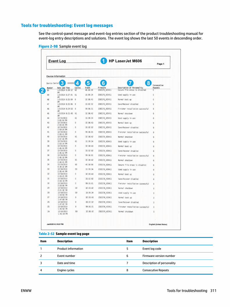
Tools for troubleshooting: Event log messages
See the control-panel message and event-log entries section of the product troubleshooting manual for event-log entry descriptions and solutions. The event log shows the last 50 events in descending order.
Figure 2-98 Sample event log
5 6
1
23 4 87
HP LaserJet M606
Table 2-52 Sample event log page
Item Description Item Description
1 Product information 5 Event log code
2 Event number 6 Firmware version number
3 Date and time 7 Description of personality
4 Engine cycles 8 Consecutive Repeats
ENWW Tools for troubleshooting 311

Print or view an event log
NOTE: The event log in using the Administration menu shows only a subset of events. For a complete event log, use the Service menu.
Print the event log from the Administration menu (touchscreen control panel)
1. From the Home screen on the product control panel, scroll to and touch the Administration button.
2. Open the following menus:
● Troubleshooting
● Event Log
3. The event log displays on the screen. To print it, touch the Print button.
Print the event log from the Administration menu (LCD control panel)
1. From the Home screen on the product control panel, use the down arrow button to scroll to Administration, and then press the OK button.
2. Use the down arrow button to scroll to Troubleshooting, and then press the OK button to select it.
3. With Print Event Log highlighted, press the OK button to print the page.
Print the event log from the Service menu (touchscreen control panel)
1. From the Home screen on the product control panel, scroll to and touch the Device Maintenance button.
2. Open the Service menu.
3. On the sign-in screen, select the Service Access Code option from the drop-down list.
4. Enter the following service access code for the product:
● 04060615
● 04060515
● 04060415
5. The event log displays on the screen. To print it, touch the Print button.
Print the event log from the Service menu (LCD control panel)
1. From the Home screen on the product control panel, use the down arrow button to scroll to Device Maintenance, and then press the OK button.
2. Use the down arrow button to scroll to Service, and then press the OK button to select it.
3. Use the down arrow button to scroll to Service Access Code, and then press the OK button to select it.
4. Enter the following service access code for the product:
NOTE: After entering the PIN, press the OK button.
312 Chapter 2 Solve problems ENWW
● 04060615
● 04060515
● 04060415
5. With Print Event Log highlighted, press the OK button to print the page.
Clear the event log
Clear the event log from a touchscreen control panel
1. From the Home screen on the product control panel, scroll to and touch the Device Maintenance button.
2. Open the Service menu.
3. On the sign-in screen, select the Service Access Code option from the drop-down list.
4. Enter the following service access code for the product:
● 04060615
● 04060515
● 04060415
5. Select the Clear Event Log item, and then touch the OK button.
Clear the event log from a LCD control panel
1. From the Home screen on the product control panel, use the down arrow button to scroll to Device Maintenance, and then press the OK button.
2. Use the down arrow button to scroll to Service, and then press the OK button to select it.
3. Use the down arrow button to scroll to Service Access Code, and then press the OK button to select it.
4. Enter the following service access code for the product:
NOTE: After entering the PIN, press the OK button.
● 04060615
● 04060515
● 04060415
5. Use the down arrow button to scroll to Clear Event Log, and then press the OK button.
ENWW Tools for troubleshooting 313

Solve image-quality problems● Improve print quality
Improve print qualityUse the information in this section to diagnose and solve image-quality problems.
NOTE: Often print-quality problems can be resolved easily by making sure that the printer is well-maintained, using paper that meets HP specifications, or running a cleaning page.
Repetitive image defect ruler
When troubleshooting the source of some print image defects, one solution is to identify if it is a repetitive defect (does the print quality defect appear multiple times on the printed page?). If this is the case, use a ruler to measure occurrences of repetitive image defects to help solve image-quality problems. For more information, see Use a ruler to measure between repetitive defects on page 315.
Use a ruler to measure occurrences of repetitive image defects to help solve image-quality problems. Place the ruler next to the first occurrence of the defect on the page. Find the distance between identical defects and use the table below to identify the component that is causing the defect.
IMPORTANT: Do not use solvents or oils to clean rollers. Instead, rub the roller with lint-free paper. If dirt is difficult to remove, rub the roller with lint-free paper that has been dampened with water.
NOTE: Defects on the tray pickup rollers or the Tray 1 pickup roller do not cause a repetitive defect. Defects on these rollers cause a defect to appear only on the leading edge of the image.
TIP: To make a product specific repetitive defect ruler, use a metric ruler to transfer the measurements in Table 2-53 Repetitive defects on page 314 to a transparency or the edge of a piece of paper—clearly label each ruler mark with the associated defective assembly.
Table 2-53 Repetitive defects
Assembly Distance between defects
Primary charging roller1 37.7 mm (1.5 in)
Transfer roller 47 mm (1.85 in)
Developer roller 63 mm (2.5 in)
Tray 1 pickup roller 63 mm (2.5 in)
Tray 1 feed roller
Tray 1 separation roller
79 mm (3.1 in)
Tray 2 feed roller
Tray 2 pickup roller
Tray 2 separation roller
79 mm (3.1 in)
Fuser sleeve unit or pressure roller2 94 mm (3.75 in)
314 Chapter 2 Solve problems ENWW
Table 2-53 Repetitive defects (continued)
Assembly Distance between defects
Photosensitive drum1 94 mm (3.75 in)
1 The primary charging roller and photosensitive drum cannot be cleaned because they are internal assemblies in the toner cartridge. If one of these assemblies is causing the defect, replace the toner cartridge.
2 The primary fuser sleeve unit or pressure roller cannot be cleaned because they are internal assemblies in the fuser. If one of these assemblies is causing the defect, replace the fuser.
Use a ruler to measure between repetitive defects
1. Identify a repetitive defect on the page.
The example pages below show the following types of repetitive defects.
NOTE: These are examples only, other types of repetitive defects might appear on a page.
● Lines (callout 1)
● Smudges (callout 2)
● Dots or spots (callout 3)
ENWW Solve image-quality problems 315

Figure 2-99 Examples of repetitive defects
1 2
3
316 Chapter 2 Solve problems ENWW
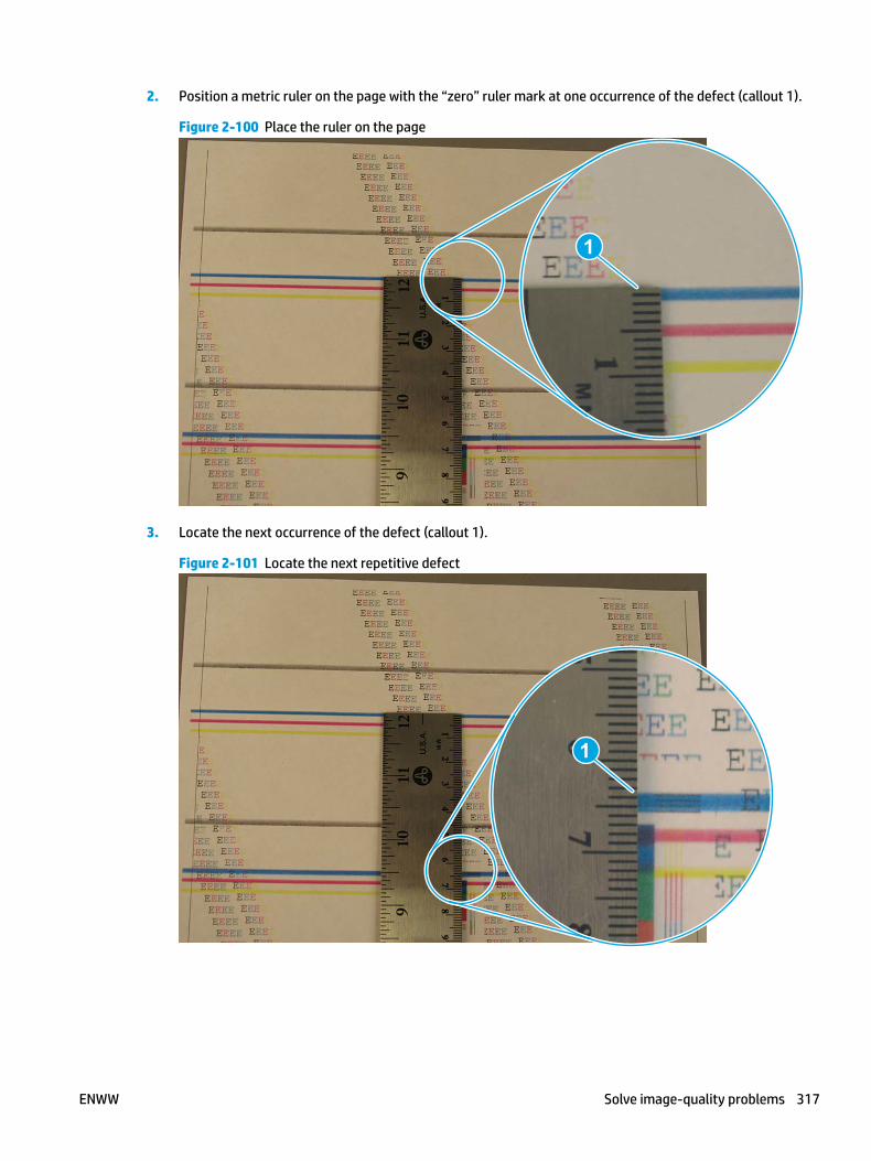
2. Position a metric ruler on the page with the “zero” ruler mark at one occurrence of the defect (callout 1).
Figure 2-100 Place the ruler on the page
1
3. Locate the next occurrence of the defect (callout 1).
Figure 2-101 Locate the next repetitive defect
1
ENWW Solve image-quality problems 317
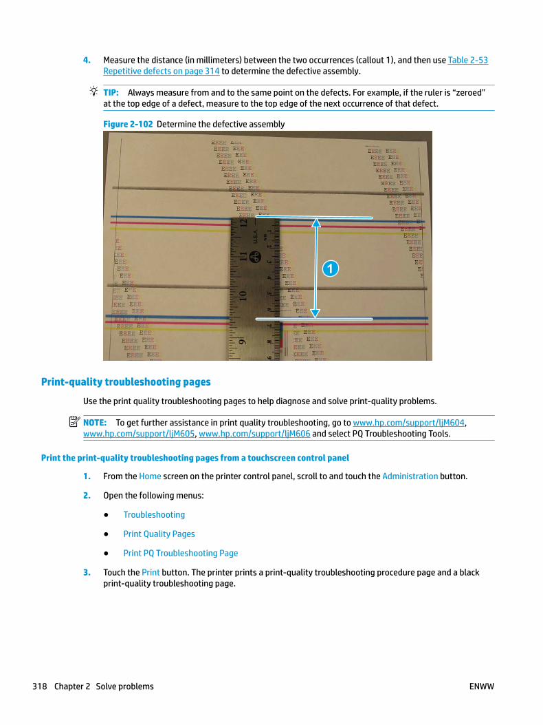
4. Measure the distance (in millimeters) between the two occurrences (callout 1), and then use Table 2-53 Repetitive defects on page 314 to determine the defective assembly.
TIP: Always measure from and to the same point on the defects. For example, if the ruler is “zeroed” at the top edge of a defect, measure to the top edge of the next occurrence of that defect.
Figure 2-102 Determine the defective assembly
1
Print-quality troubleshooting pages
Use the print quality troubleshooting pages to help diagnose and solve print-quality problems.
NOTE: To get further assistance in print quality troubleshooting, go to www.hp.com/support/ljM604, www.hp.com/support/ljM605, www.hp.com/support/ljM606 and select PQ Troubleshooting Tools.
Print the print-quality troubleshooting pages from a touchscreen control panel
1. From the Home screen on the printer control panel, scroll to and touch the Administration button.
2. Open the following menus:
● Troubleshooting
● Print Quality Pages
● Print PQ Troubleshooting Page
3. Touch the Print button. The printer prints a print-quality troubleshooting procedure page and a black print-quality troubleshooting page.
318 Chapter 2 Solve problems ENWW
Print the print-quality troubleshooting pages from a LCD control panel
1. From the Home screen on the printer control panel, use the down arrow button to scroll to Administration, and then press the OK button.
2. Use the down arrow button to scroll to Troubleshooting, and then press the OK button.
3. Use the down arrow button to scroll to Print Quality Pages, and then press the OK button to print the page.
4. Use the down arrow button to scroll to Print PQ Troubleshooting Page, and then press the OK button to print the page.
NOTE: The printer returns to the Ready state after printing the print-quality-troubleshooting pages. Follow the instructions on the pages that print out.
ENWW Solve image-quality problems 319

Figure 2-103 Print-quality troubleshooting procedure page
320 Chapter 2 Solve problems ENWW
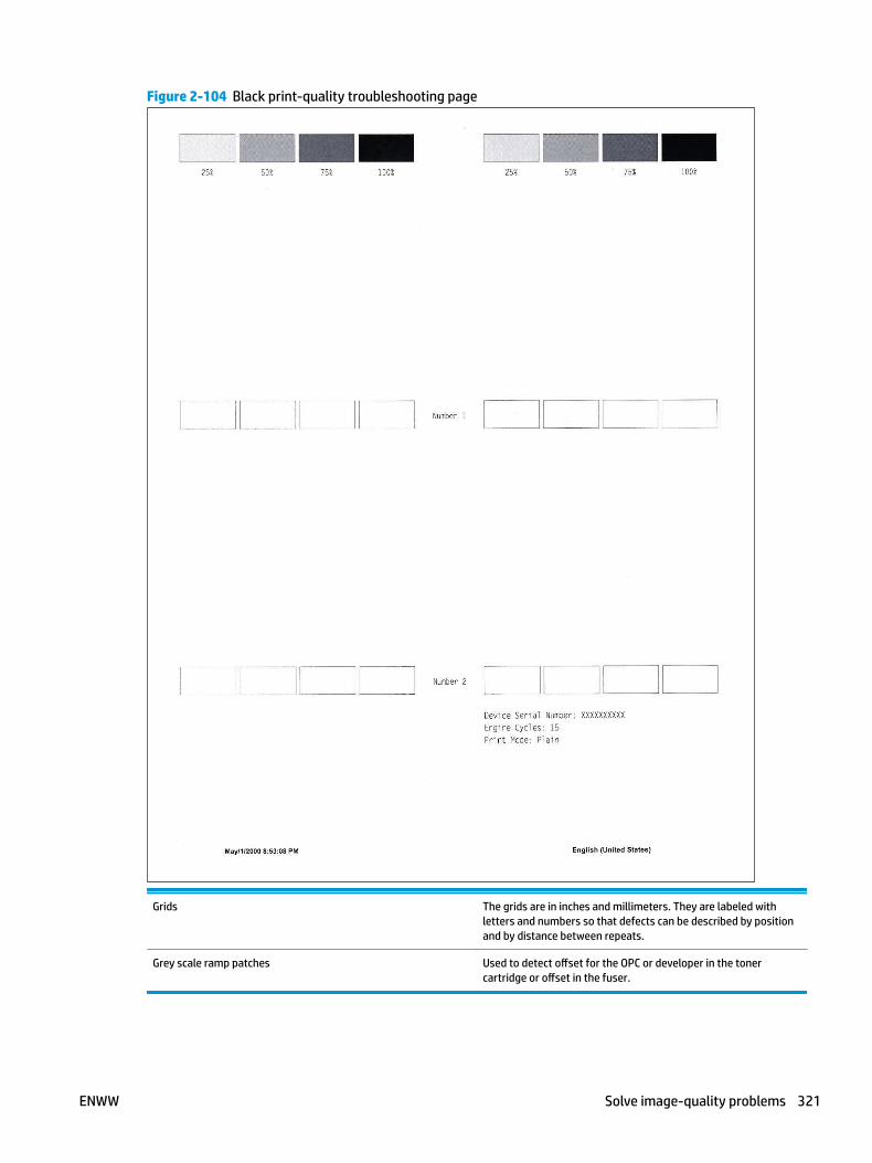
Figure 2-104 Black print-quality troubleshooting page
Grids The grids are in inches and millimeters. They are labeled with letters and numbers so that defects can be described by position and by distance between repeats.
Grey scale ramp patches Used to detect offset for the OPC or developer in the toner cartridge or offset in the fuser.
ENWW Solve image-quality problems 321

Print from a different software program
Try printing from a different software program. If the page prints correctly, the problem is with the original software program.
Check the paper-type setting for the print job
Check the paper type setting when printing from a software program and the printed pages have smears, fuzzy or dark print, curled paper, scattered dots of toner, loose toner, or small areas of missing toner.
Check the paper type setting (Windows)
1. From the software program, select the Print option.
2. Select the printer, and then click the Properties or Preferences button.
3. Click the Paper/Quality tab.
4. From the Paper Type drop-down list, click the More... option.
5. Expand the list of Type is: options.
6. Expand the category of paper types that best describes your paper.
7. Select the option for the type of paper you are using, and click the OK button.
8. Click the OK button to close the Document Properties dialog box. In the Print dialog box, click the OK button to print the job.
Check the paper type setting (Mac OS X)
1. Click the File menu, and then click the Print option.
2. In the Printer menu, select the printer.
3. By default, the print driver displays the Copies & Pages menu. Open the menus drop-down list, and then click the Finishing menu.
4. Select a type from the Media Type drop-down list.
5. Click the Print button.
Check toner-cartridge status
Print the supplies status page from a touchscreen control panel
1. From the Home screen on the printer control panel, scroll to and touch the Administration button.
2. Open the following menus:
● Reports
● Configuration/Status Pages
3. Touch Supplies Status Page, and then press the Print button to print the page.
322 Chapter 2 Solve problems ENWW
Print the supplies status page from a LCD control panel
1. From the Home screen on the printer control panel, use the down arrow button to scroll to Administration, and then press the OK button.
2. Open the following menus:
● Reports
● Configuration/Status Pages
3. Use the down arrow button to scroll to Supplies Status, and then press the OK button to select it.
4. Use the up arrow button to scroll to Print, and then press the OK button to print the page.
Check the supplies status page for the following information:
● Estimated percentage of cartridge or cartridges life remaining
● Approximate pages remaining
● Part number or numbers for HP toner cartridge or cartridges
● Number of pages printed
Clean the printer
During the printing process paper, toner, and dust particles can accumulate inside the printer and can cause print-quality issues such as toner specks or spatter, smears, streaks, lines, or repeating marks.
Print a cleaning page
Print the cleaning from a touchscreen control panel
1. From the Home screen on the printer control panel, scroll to and touch the Device Maintenance button.
2. Open the following menus:
● Calibration/Cleaning
3. Touch Cleaning Page, and then press the OK button to print the page.
4. The cleaning process can take several minutes. When it is finished, discard the printed page.
Print the cleaning page from a LCD control panel
1. From the Home screen on the printer control panel, use the down arrow button to scroll to Device Maintenance, and then press the OK button.
2. Use the down arrow button to scroll to Calibration/Cleaning, and then press the OK button.
3. If necessary, use the down arrow button to scroll to Cleaning, and then press the OK button to print the page.
4. Follow the instruction on the printed cleaning page to finish the cleaning page process.
ENWW Solve image-quality problems 323
Visually inspect the toner cartridge or cartridges
1. Remove the toner cartridge or cartridges from the printer, and verify that the sealing tape has been removed.
2. Check the memory chip for damage.
3. Examine the surface of the imaging drum on the cartridge.
CAUTION: Do not touch the roller (imaging drum). Fingerprints on the imaging drum can cause print-quality problems.
4. If you see any scratches, fingerprints, or other damage on an imaging drum, replace the toner cartridge or cartridges.
5. If the imaging drum does not appear to be damaged, rock the toner cartridge or cartridges gently several times and reinstall it. Print a few pages to see if the problem has resolved.
Check paper and the printing environment
Step one: Use paper that meets HP specifications
● Always use a paper type and weight that this printer supports.
● Use paper that is of good quality and free of cuts, nicks, tears, spots, loose particles, dust, wrinkles, voids, staples, and curled or bent edges.
● Use paper that has not been previously printed on.
● Use paper that does not contain metallic material, such as glitter.
● Use paper that is designed for use in laser printers. Do not use paper that is designed only for use in Inkjet printers.
● Use paper that is not too rough. Using smoother paper generally results in better print quality
Step two: Check the environment
The environment can directly affect print quality and is a common cause for print-quality or paper-feeding issues. Try the following solutions:
● Move the printer away from drafty locations, such as open windows or doors, or air-conditioning vents.
● Make sure the printer is not exposed to temperatures or humidity outside of printer specifications.
● Do not place the printer in a confined space, such as a cabinet.
● Place the printer on a sturdy, level surface.
● Remove anything that is blocking the vents on the printer. The printer requires good air flow on all sides, including the top.
● Protect the printer from airborne debris, dust, steam, grease, or other elements that can leave residue inside the printer.
Use manual print modes
Try the following manual print modes to see if they solve the image-quality problems.
324 Chapter 2 Solve problems ENWW
NOTE: Tray 1 and Tray 2 are optimal for paper pickup when using special paper or media other than 20lb plain paper. For Tray 1 and Tray 2 the printer increases the number of attempts to pickup a page, which increases the reliability of successfully picking the page from the tray and decreases the possibility of a mis-pick jam.
HP recommends using Tray 1 or Tray 2 if the printer is experiencing excessive or reoccurring jams from trays other than Tray 1 and Tray 2, or for print jobs that require media other than 20lb plain paper.
Select a manual print mode from a touch screen control panel
1. From the Home screen on the printer control panel, scroll to and touch the Administration button.
2. Open the following menus:
● General Settings
● Print Quality
● Adjust Paper Types or Optimize
3. Select a paper type, and then select the mode to adjust.
4. Select a value for the mode, and then touch the Save button.
Select a manual print mode from a LCD control panel
1. From the Home screen on the printer control panel, use the down arrow button to scroll to Administration, and then press the OK button.
2. Use the down arrow button to scroll to General Settings, and then press the OK button.
3. Use the down arrow button to scroll to Print Quality, and then press the OK button.
4. Use the down arrow button to scroll to Adjust Paper Types or Optimize, and then press the OK button.
ENWW Solve image-quality problems 325
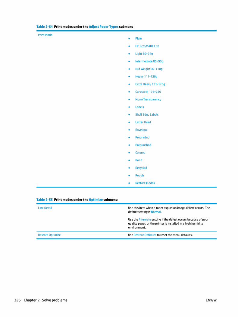
Table 2-54 Print modes under the Adjust Paper Types submenu
Print Mode● Plain
● HP EcoSMART Lite
● Light 60–74g
● Intermediate 85–90g
● Mid Weight 96–110g
● Heavy 111-130g
● Extra Heavy 131-175g
● Cardstock 176–220
● Mono Transparency
● Labels
● Shelf Edge Labels
● Letter Head
● Envelope
● Preprinted
● Prepunched
● Colored
● Bond
● Recycled
● Rough
● Restore Modes
Table 2-55 Print modes under the Optimize submenu
Line Detail Use this item when a toner explosion image defect occurs. The default setting is Normal.
Use the Alternate setting if the defect occurs because of poor quality paper, or the printer is installed in a high humidity environment.
Restore Optimize Use Restore Optimize to reset the menu defaults.
326 Chapter 2 Solve problems ENWW

Image defects table
The following examples depict letter-size paper that has passed through the printer short-edge first. These examples illustrate problems that would affect all the printed pages, whether they are printed in color or in black only.
Table 2-56 Image defects table
Problem Sample Cause Solution
Print is light or faded on entire page.
Poor contact exists between the transfer roller and its shaft.
Clean the contact. If the problem remains after cleaning, check the contact for damage. Replace any deformed or damaged parts.
Image is too dark. Poor contact exists in the primary charging bias or developing bias contacts between the toner cartridge and the printer.
Clean each toner cartridge contact. If the problem remains after cleaning, check the contacts for damage. Replace any deformed or damaged parts. Replace the toner cartridge.
Page is blank. Poor developing bias contact exists with the cartridge.
Clean the contact. If the problem remains after cleaning, check the contact for damage. Replace any deformed or damaged parts.
The laser shutter open-close projection part of the cartridge is damaged.
Replace the toner cartridge.
The laser shutter arm and the laser shutter are malfunctioning or damaged.
If the laser shutter arm or the laser shutter does not move smoothly or if any part is damaged, replace any defective part.
The laser/scanner is defective. Replace the laser/scanner.
ENWW Solve image-quality problems 327
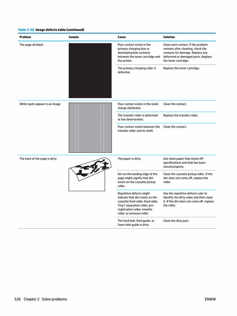
Table 2-56 Image defects table (continued)
Problem Sample Cause Solution
The page all black. Poor contact exists in the primary charging bias or developing bias contacts between the toner cartridge and the printer.
Clean each contact. If the problem remains after cleaning, check the contacts for damage. Replace any deformed or damaged parts. Replace the toner cartridge.
The primary charging roller is defective.
Replace the toner cartridge.
White spots appear in an image Poor contact exists in the static charge eliminator.
Clean the contact.
The transfer roller is deformed or has deteriorated.
Replace the transfer roller.
Poor contact exists between the transfer roller and its shaft.
Clean the contact.
The back of the page is dirty. The paper is dirty. Use clean paper that meets HP specifications and that has been stored properly.
Dirt on the leading edge of the page might signify that dirt exists on the cassette pickup roller.
Clean the cassette pickup roller. If the dirt does not come off, replace the roller.
Repetitive defects might indicate that dirt exists on the cassette feed roller, feed roller, Tray1 separation roller, pre-registration roller, transfer roller, or pressure roller.
Use the repetitive defects ruler to identify the dirty roller and then clean it. If the dirt does not come off, replace the roller.
The feed belt, feed guide, or fuser inlet guide is dirty.
Clean the dirty part.
328 Chapter 2 Solve problems ENWW
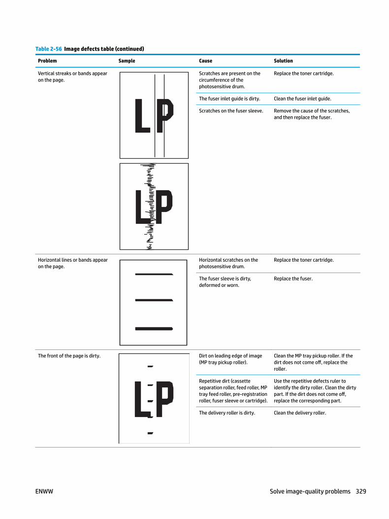
Table 2-56 Image defects table (continued)
Problem Sample Cause Solution
Vertical streaks or bands appear on the page.
Scratches are present on the circumference of the photosensitive drum.
Replace the toner cartridge.
The fuser inlet guide is dirty. Clean the fuser inlet guide.
Scratches on the fuser sleeve. Remove the cause of the scratches, and then replace the fuser.
Horizontal lines or bands appear on the page.
Horizontal scratches on the photosensitive drum.
Replace the toner cartridge.
The fuser sleeve is dirty, deformed or worn.
Replace the fuser.
The front of the page is dirty. Dirt on leading edge of image (MP tray pickup roller).
Clean the MP tray pickup roller. If the dirt does not come off, replace the roller.
Repetitive dirt (cassette separation roller, feed roller, MP tray feed roller, pre-registration roller, fuser sleeve or cartridge).
Use the repetitive defects ruler to identify the dirty roller. Clean the dirty part. If the dirt does not come off, replace the corresponding part.
The delivery roller is dirty. Clean the delivery roller.
ENWW Solve image-quality problems 329
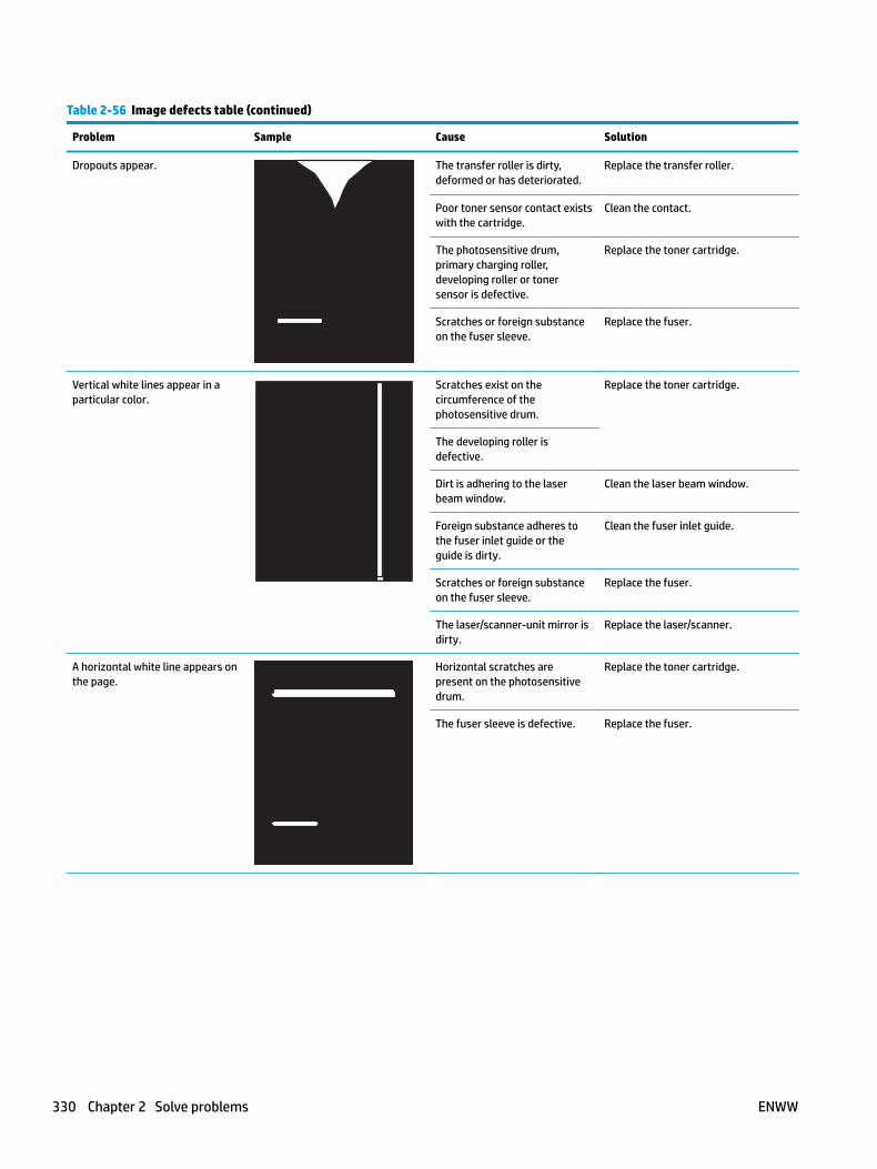
Table 2-56 Image defects table (continued)
Problem Sample Cause Solution
Dropouts appear. The transfer roller is dirty, deformed or has deteriorated.
Replace the transfer roller.
Poor toner sensor contact exists with the cartridge.
Clean the contact.
The photosensitive drum, primary charging roller, developing roller or toner sensor is defective.
Replace the toner cartridge.
Scratches or foreign substance on the fuser sleeve.
Replace the fuser.
Vertical white lines appear in a particular color.
Scratches exist on the circumference of the photosensitive drum.
Replace the toner cartridge.
The developing roller is defective.
Dirt is adhering to the laser beam window.
Clean the laser beam window.
Foreign substance adheres to the fuser inlet guide or the guide is dirty.
Clean the fuser inlet guide.
Scratches or foreign substance on the fuser sleeve.
Replace the fuser.
The laser/scanner-unit mirror is dirty.
Replace the laser/scanner.
A horizontal white line appears on the page.
Horizontal scratches are present on the photosensitive drum.
Replace the toner cartridge.
The fuser sleeve is defective. Replace the fuser.
330 Chapter 2 Solve problems ENWW
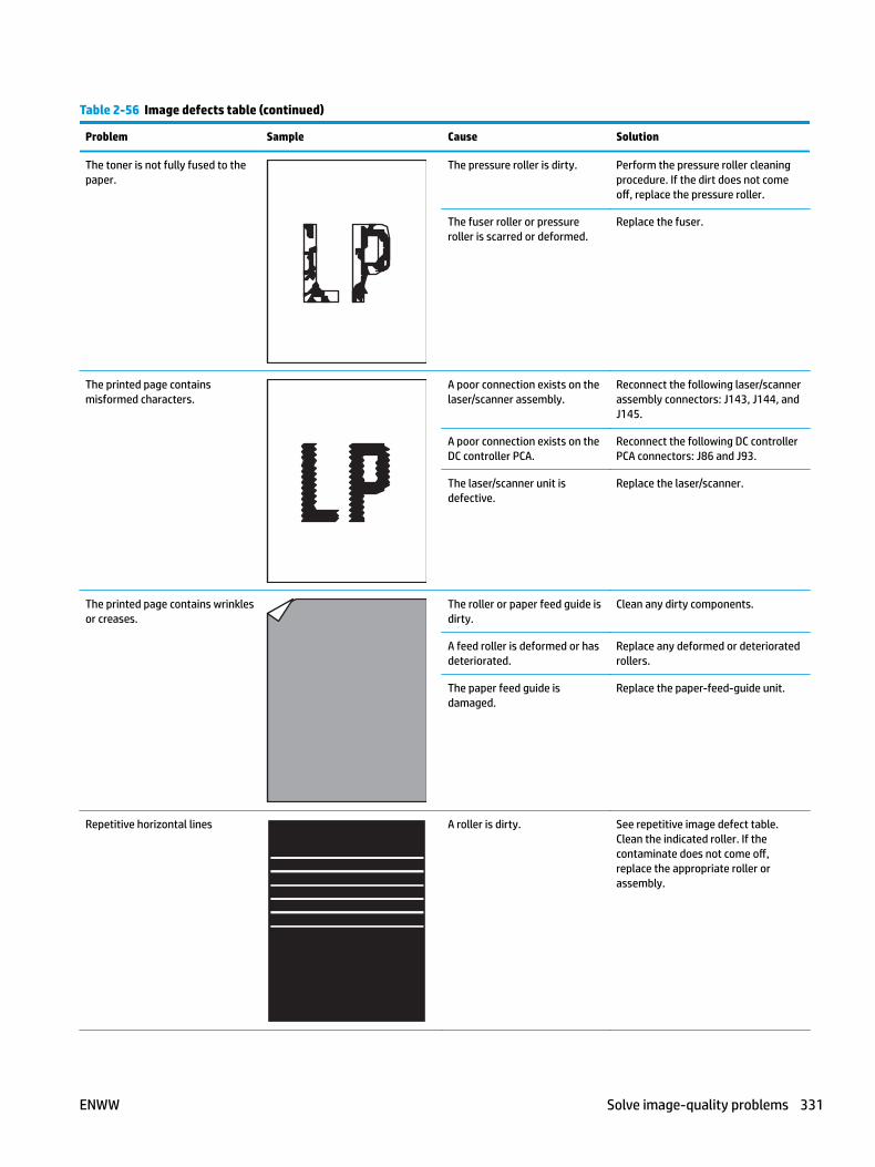
Table 2-56 Image defects table (continued)
Problem Sample Cause Solution
The toner is not fully fused to the paper.
The pressure roller is dirty. Perform the pressure roller cleaning procedure. If the dirt does not come off, replace the pressure roller.
The fuser roller or pressure roller is scarred or deformed.
Replace the fuser.
The printed page contains misformed characters.
A poor connection exists on the laser/scanner assembly.
Reconnect the following laser/scanner assembly connectors: J143, J144, and J145.
A poor connection exists on the DC controller PCA.
Reconnect the following DC controller PCA connectors: J86 and J93.
The laser/scanner unit is defective.
Replace the laser/scanner.
The printed page contains wrinkles or creases.
The roller or paper feed guide is dirty.
Clean any dirty components.
A feed roller is deformed or has deteriorated.
Replace any deformed or deteriorated rollers.
The paper feed guide is damaged.
Replace the paper-feed-guide unit.
Repetitive horizontal lines A roller is dirty. See repetitive image defect table. Clean the indicated roller. If the contaminate does not come off, replace the appropriate roller or assembly.
ENWW Solve image-quality problems 331
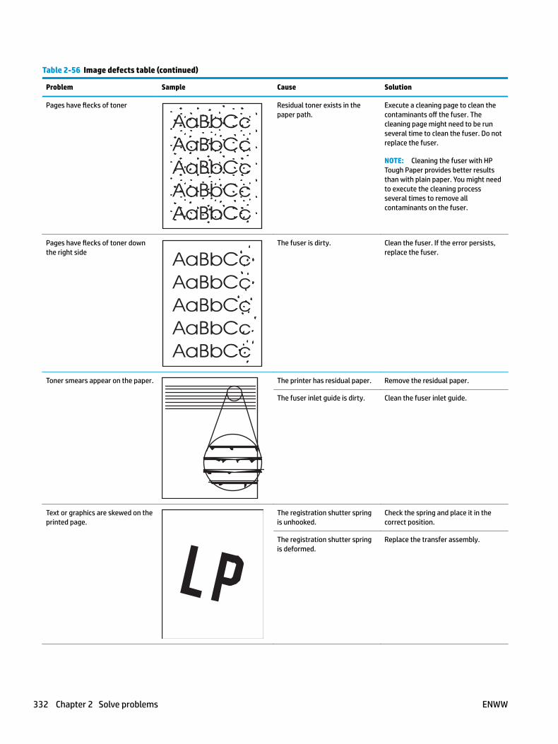
Table 2-56 Image defects table (continued)
Problem Sample Cause Solution
Pages have flecks of toner Residual toner exists in the paper path.
Execute a cleaning page to clean the contaminants off the fuser. The cleaning page might need to be run several time to clean the fuser. Do not replace the fuser.
NOTE: Cleaning the fuser with HP Tough Paper provides better results than with plain paper. You might need to execute the cleaning process several times to remove all contaminants on the fuser.
Pages have flecks of toner down the right side
The fuser is dirty. Clean the fuser. If the error persists, replace the fuser.
Toner smears appear on the paper. The printer has residual paper. Remove the residual paper.
The fuser inlet guide is dirty. Clean the fuser inlet guide.
Text or graphics are skewed on the printed page.
The registration shutter spring is unhooked.
Check the spring and place it in the correct position.
The registration shutter spring is deformed.
Replace the transfer assembly.
332 Chapter 2 Solve problems ENWW
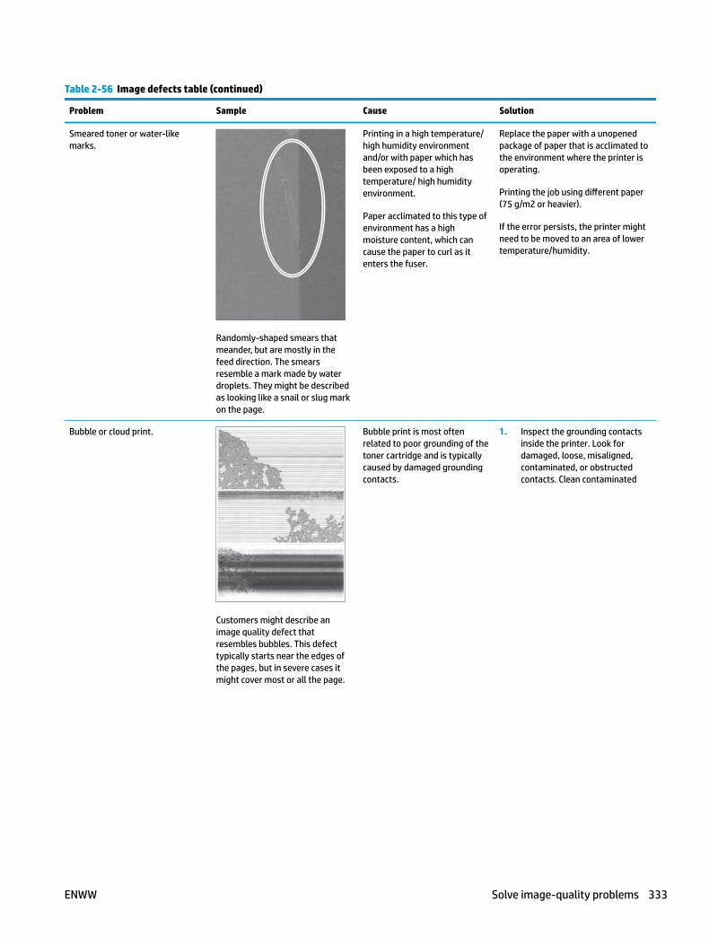
Table 2-56 Image defects table (continued)
Problem Sample Cause Solution
Smeared toner or water-like marks.
Randomly-shaped smears that meander, but are mostly in the feed direction. The smears resemble a mark made by water droplets. They might be described as looking like a snail or slug mark on the page.
Printing in a high temperature/ high humidity environment and/or with paper which has been exposed to a high temperature/ high humidity environment.
Paper acclimated to this type of environment has a high moisture content, which can cause the paper to curl as it enters the fuser.
Replace the paper with a unopened package of paper that is acclimated to the environment where the printer is operating.
Printing the job using different paper (75 g/m2 or heavier).
If the error persists, the printer might need to be moved to an area of lower temperature/humidity.
Bubble or cloud print.
Customers might describe an image quality defect that resembles bubbles. This defect typically starts near the edges of the pages, but in severe cases it might cover most or all the page.
Bubble print is most often related to poor grounding of the toner cartridge and is typically caused by damaged grounding contacts.
1. Inspect the grounding contacts inside the printer. Look for damaged, loose, misaligned, contaminated, or obstructed contacts. Clean contaminated
ENWW Solve image-quality problems 333
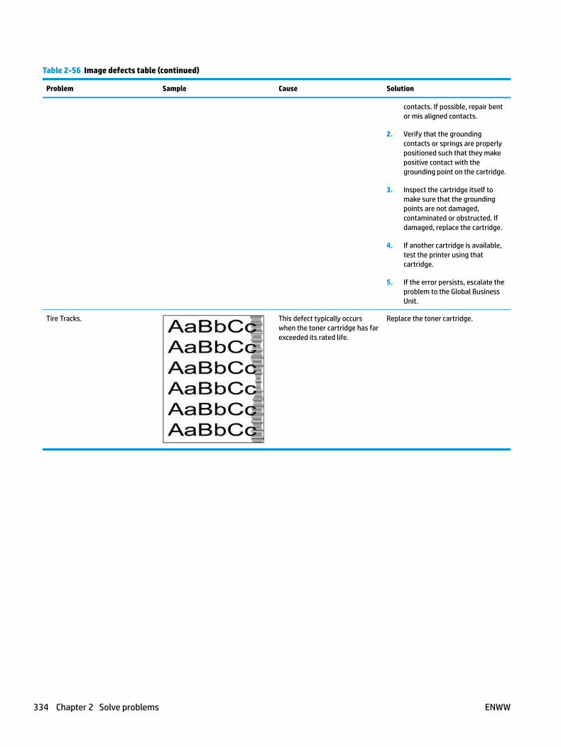
Table 2-56 Image defects table (continued)
Problem Sample Cause Solution
contacts. If possible, repair bent or mis aligned contacts.
2. Verify that the grounding contacts or springs are properly positioned such that they make positive contact with the grounding point on the cartridge.
3. Inspect the cartridge itself to make sure that the grounding points are not damaged, contaminated or obstructed. If damaged, replace the cartridge.
4. If another cartridge is available, test the printer using that cartridge.
5. If the error persists, escalate the problem to the Global Business Unit.
Tire Tracks. This defect typically occurs when the toner cartridge has far exceeded its rated life.
Replace the toner cartridge.
334 Chapter 2 Solve problems ENWW

Clean the printerNOTE: To clean the printer exterior, use a soft, water-moistened cloth.
● Clean the paper path
● Print a cleaning page
● Clean the Tray 1 rollers
● Clean the Tray 2-X rollers
● Clean the 1,500-sheet high capacity input (HCI) feeder rollers
Clean the paper pathOver time, particles of toner and paper accumulate inside the printer. This can cause print-quality problems during printing. Cleaning the paper path eliminates or reduces these problems.
Clean the paper path and toner-cartridge areas every time that the toner cartridge is changed or whenever print-quality problems occur. As much as possible, keep the printer free from dust and debris.
Print a cleaning page
Print the cleaning from a touchscreen control panel
1. From the Home screen on the printer control panel, scroll to and touch the Device Maintenance button.
2. Open the following menus:
● Calibration/Cleaning
3. Touch Cleaning Page, and then press the OK button to print the page.
4. The cleaning process can take several minutes. When it is finished, discard the printed page.
Print the cleaning page from an LCD control panel
1. From the Home screen on the printer control panel, use the down arrow button to scroll to Device Maintenance, and then press the OK button.
2. Use the down arrow button to scroll to Calibration/Cleaning, and then press the OK button.
3. If necessary, use the down arrow button to scroll to Cleaning, and then press the OK button to print the page.
4. Follow the instruction on the printed cleaning page to finish the cleaning page process.
ENWW Clean the printer 335

Clean the Tray 1 rollers
Step 1: Remove the Tray 1 rollers
CAUTION: When handling the rollers, avoid touching the roller surfaces. Skin oils and fingerprints on a roller surface can cause print-quality problems.
1. Open the front cover.
Figure 2-105 Open the front cover
2. Rotate the spring-loaded cover downward to gain access to the separation roller.
NOTE: The envelope feeder cover is not shown in this figure. The cover might be installed in this area (callout 1) on some printers.
Figure 2-106 Open the separation roller cover
336 Chapter 2 Solve problems ENWW
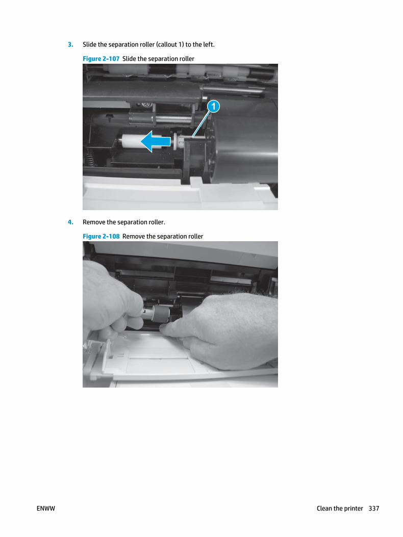
3. Slide the separation roller (callout 1) to the left.
Figure 2-107 Slide the separation roller
1
4. Remove the separation roller.
Figure 2-108 Remove the separation roller
ENWW Clean the printer 337

5. Remove one screw (callout 1).
Figure 2-109 Remove one screw
1
6. Push down on the roller-shaft bushing (callout 1) to release two alignment pins, and then slide the bushing to the left and off of the shaft to remove it.
Figure 2-110 Remove the bushing
1
338 Chapter 2 Solve problems ENWW
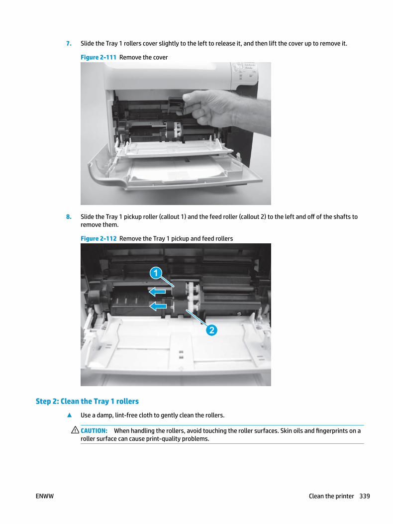
7. Slide the Tray 1 rollers cover slightly to the left to release it, and then lift the cover up to remove it.
Figure 2-111 Remove the cover
8. Slide the Tray 1 pickup roller (callout 1) and the feed roller (callout 2) to the left and off of the shafts to remove them.
Figure 2-112 Remove the Tray 1 pickup and feed rollers
1
2
Step 2: Clean the Tray 1 rollers
▲ Use a damp, lint-free cloth to gently clean the rollers.
CAUTION: When handling the rollers, avoid touching the roller surfaces. Skin oils and fingerprints on a roller surface can cause print-quality problems.
ENWW Clean the printer 339
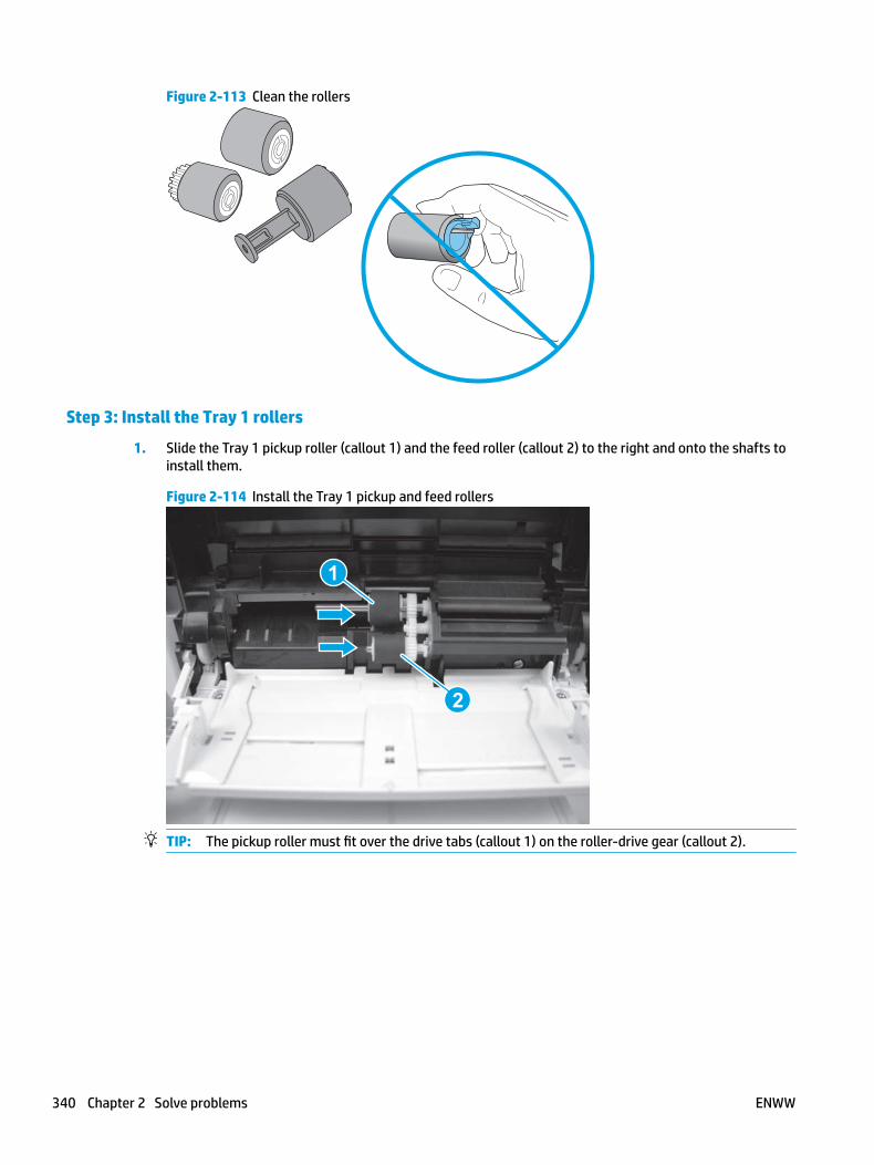
Figure 2-113 Clean the rollers
Step 3: Install the Tray 1 rollers
1. Slide the Tray 1 pickup roller (callout 1) and the feed roller (callout 2) to the right and onto the shafts to install them.
Figure 2-114 Install the Tray 1 pickup and feed rollers
1
2
TIP: The pickup roller must fit over the drive tabs (callout 1) on the roller-drive gear (callout 2).
340 Chapter 2 Solve problems ENWW

1 2
2. Position the Tray 1 rollers cover over the pickup and feed rollers (callout 1), and then slide the cover to the right (callout 2) to install it.
Figure 2-115 Remove the cover
1
2
ENWW Clean the printer 341

3. Slide the roller-shaft bushing (callout 1) to the right and onto the shaft to install it.
Figure 2-116 Install the bushing
1
4. Install one screw (callout 1).
Figure 2-117 Install one screw
1
342 Chapter 2 Solve problems ENWW
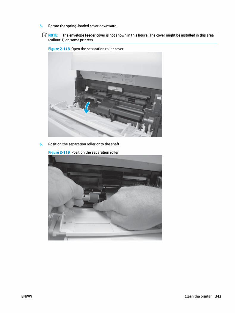
5. Rotate the spring-loaded cover downward.
NOTE: The envelope feeder cover is not shown in this figure. The cover might be installed in this area (callout 1) on some printers.
Figure 2-118 Open the separation roller cover
6. Position the separation roller onto the shaft.
Figure 2-119 Position the separation roller
ENWW Clean the printer 343

7. Slide the separation roller (callout 1) to the right until it clicks into place.
Figure 2-120 Install the separation roller
1
8. Close the front cover.
Figure 2-121 Close the front cover
344 Chapter 2 Solve problems ENWW
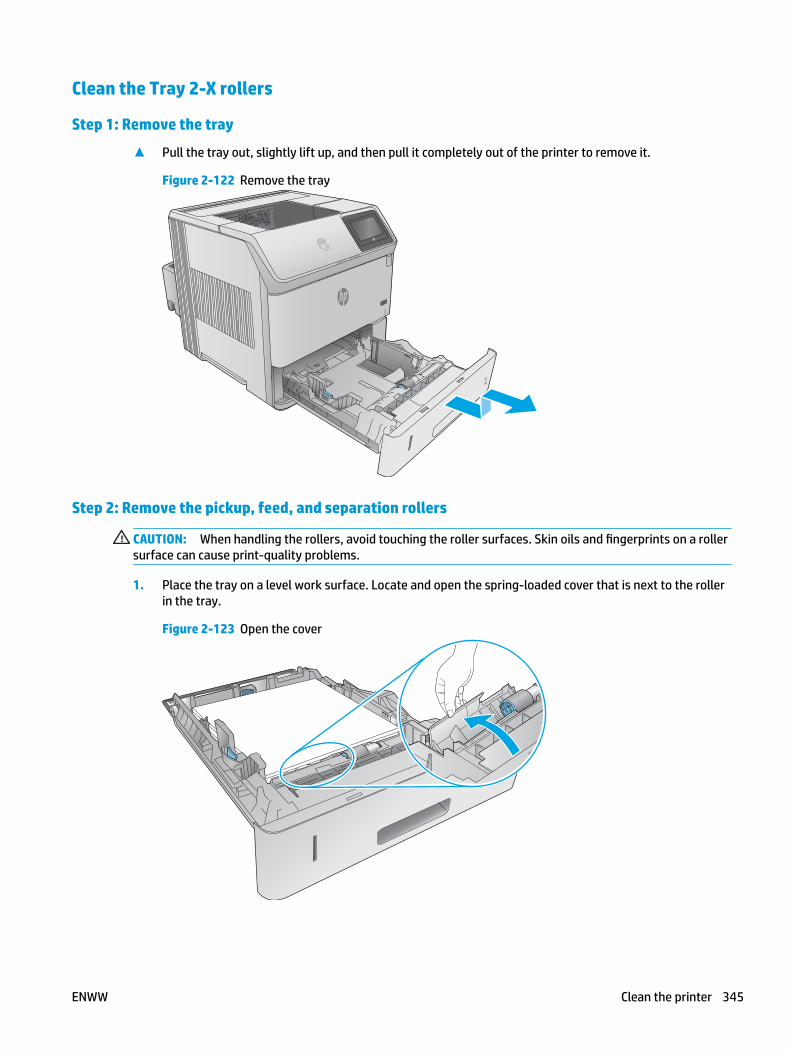
Clean the Tray 2-X rollers
Step 1: Remove the tray
▲ Pull the tray out, slightly lift up, and then pull it completely out of the printer to remove it.
Figure 2-122 Remove the tray
Step 2: Remove the pickup, feed, and separation rollers
CAUTION: When handling the rollers, avoid touching the roller surfaces. Skin oils and fingerprints on a roller surface can cause print-quality problems.
1. Place the tray on a level work surface. Locate and open the spring-loaded cover that is next to the roller in the tray.
Figure 2-123 Open the cover
ENWW Clean the printer 345
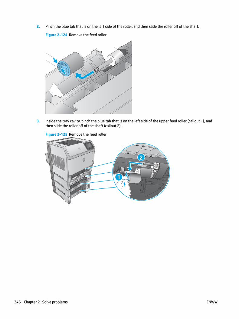
2. Pinch the blue tab that is on the left side of the roller, and then slide the roller off of the shaft.
Figure 2-124 Remove the feed roller
3. Inside the tray cavity, pinch the blue tab that is on the left side of the upper feed roller (callout 1), and then slide the roller off of the shaft (callout 2).
Figure 2-125 Remove the feed roller
1
2
346 Chapter 2 Solve problems ENWW
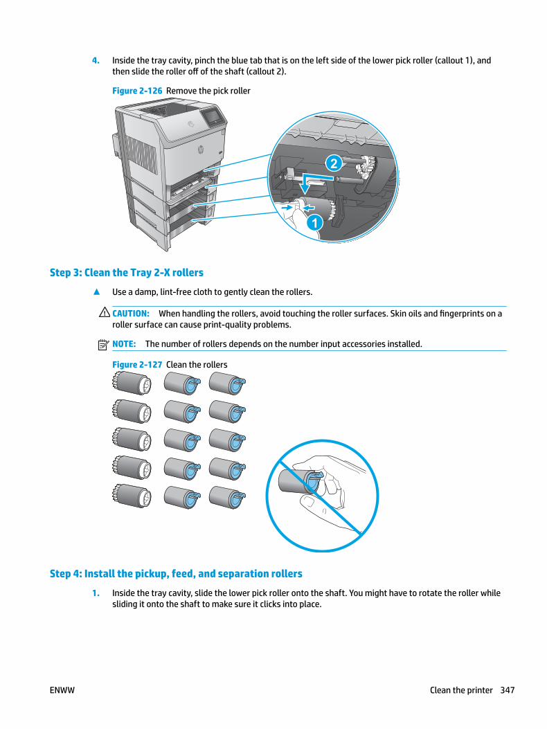
4. Inside the tray cavity, pinch the blue tab that is on the left side of the lower pick roller (callout 1), and then slide the roller off of the shaft (callout 2).
Figure 2-126 Remove the pick roller
2
1
Step 3: Clean the Tray 2-X rollers
▲ Use a damp, lint-free cloth to gently clean the rollers.
CAUTION: When handling the rollers, avoid touching the roller surfaces. Skin oils and fingerprints on a roller surface can cause print-quality problems.
NOTE: The number of rollers depends on the number input accessories installed.
Figure 2-127 Clean the rollers
Step 4: Install the pickup, feed, and separation rollers
1. Inside the tray cavity, slide the lower pick roller onto the shaft. You might have to rotate the roller while sliding it onto the shaft to make sure it clicks into place.
ENWW Clean the printer 347
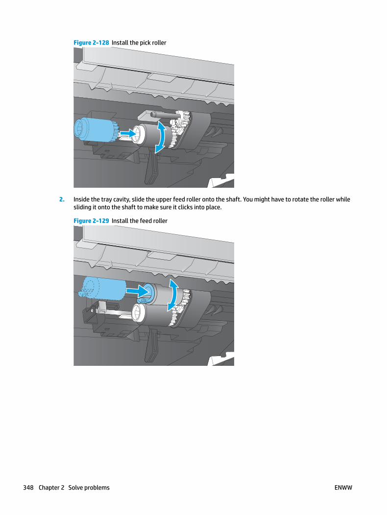
Figure 2-128 Install the pick roller
2. Inside the tray cavity, slide the upper feed roller onto the shaft. You might have to rotate the roller while sliding it onto the shaft to make sure it clicks into place.
Figure 2-129 Install the feed roller
348 Chapter 2 Solve problems ENWW
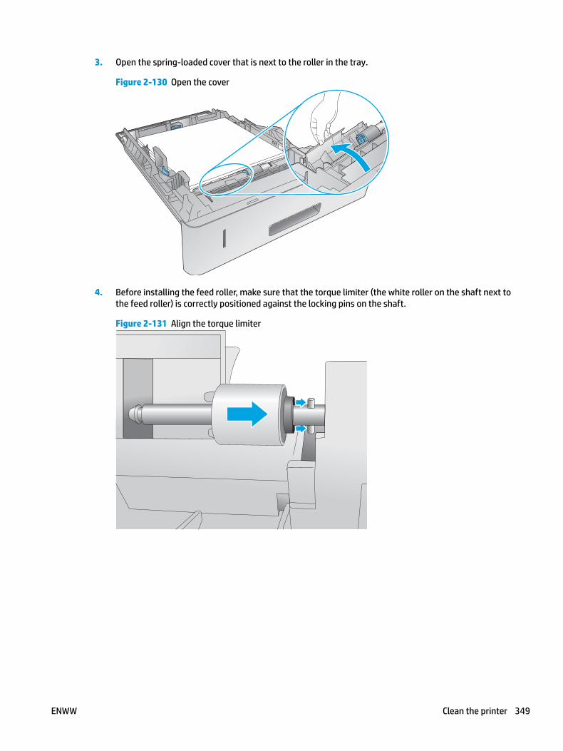
3. Open the spring-loaded cover that is next to the roller in the tray.
Figure 2-130 Open the cover
4. Before installing the feed roller, make sure that the torque limiter (the white roller on the shaft next to the feed roller) is correctly positioned against the locking pins on the shaft.
Figure 2-131 Align the torque limiter
ENWW Clean the printer 349
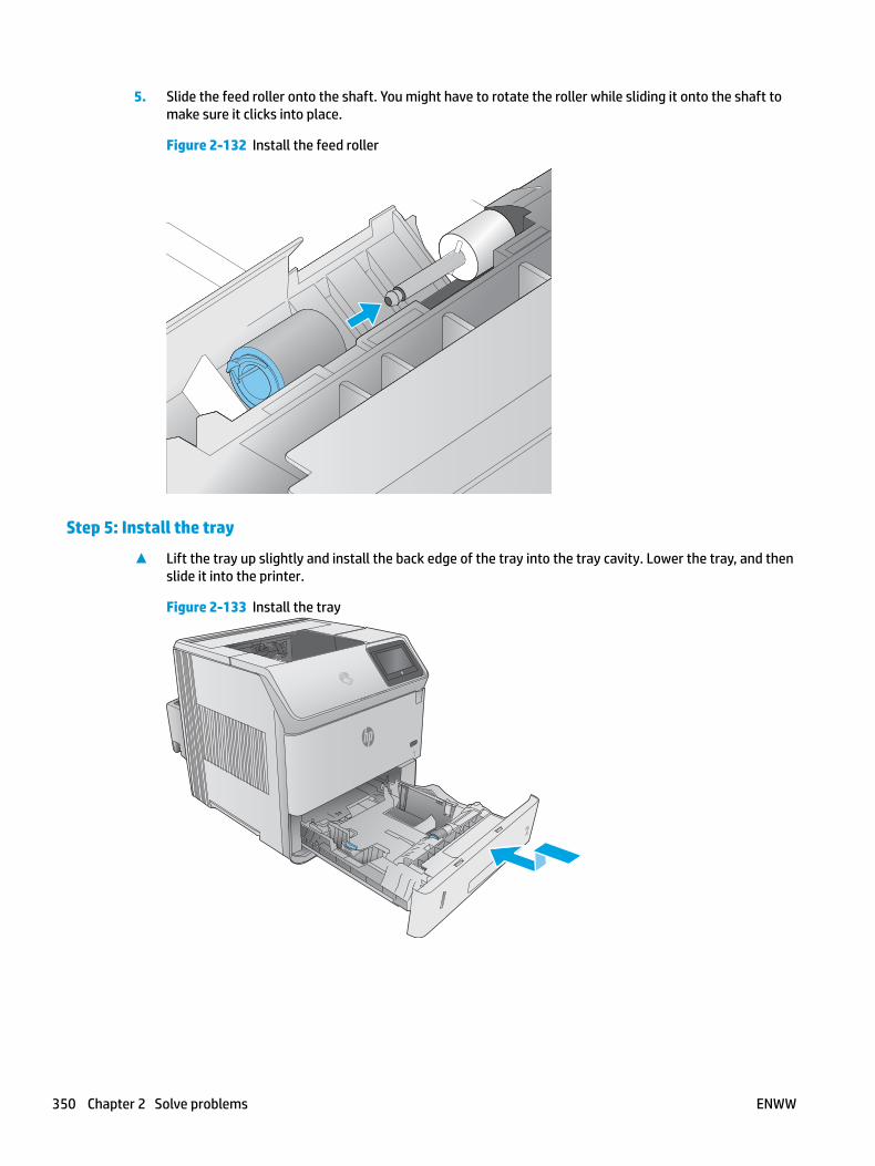
5. Slide the feed roller onto the shaft. You might have to rotate the roller while sliding it onto the shaft to make sure it clicks into place.
Figure 2-132 Install the feed roller
Step 5: Install the tray
▲ Lift the tray up slightly and install the back edge of the tray into the tray cavity. Lower the tray, and then slide it into the printer.
Figure 2-133 Install the tray
350 Chapter 2 Solve problems ENWW
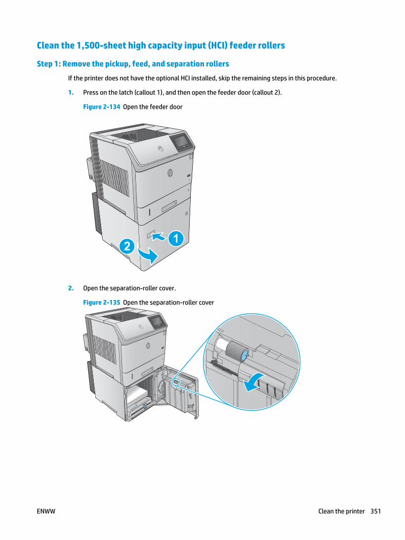
Clean the 1,500-sheet high capacity input (HCI) feeder rollers
Step 1: Remove the pickup, feed, and separation rollers
If the printer does not have the optional HCI installed, skip the remaining steps in this procedure.
1. Press on the latch (callout 1), and then open the feeder door (callout 2).
Figure 2-134 Open the feeder door
12 12
2. Open the separation-roller cover.
Figure 2-135 Open the separation-roller cover
ENWW Clean the printer 351
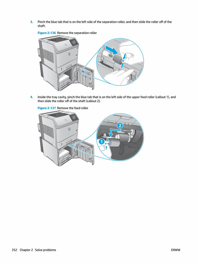
3. Pinch the blue tab that is on the left side of the separation roller, and then slide the roller off of the shaft.
Figure 2-136 Remove the separation roller
4. Inside the tray cavity, pinch the blue tab that is on the left side of the upper feed roller (callout 1), and then slide the roller off of the shaft (callout 2).
Figure 2-137 Remove the feed roller
1
2
352 Chapter 2 Solve problems ENWW
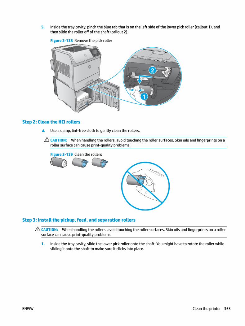
5. Inside the tray cavity, pinch the blue tab that is on the left side of the lower pick roller (callout 1), and then slide the roller off of the shaft (callout 2).
Figure 2-138 Remove the pick roller
2
1
Step 2: Clean the HCI rollers
▲ Use a damp, lint-free cloth to gently clean the rollers.
CAUTION: When handling the rollers, avoid touching the roller surfaces. Skin oils and fingerprints on a roller surface can cause print-quality problems.
Figure 2-139 Clean the rollers
Step 3: Install the pickup, feed, and separation rollers
CAUTION: When handling the rollers, avoid touching the roller surfaces. Skin oils and fingerprints on a roller surface can cause print-quality problems.
1. Inside the tray cavity, slide the lower pick roller onto the shaft. You might have to rotate the roller while sliding it onto the shaft to make sure it clicks into place.
ENWW Clean the printer 353

Figure 2-140 Install the pick roller
2. Inside the tray cavity, slide the upper feed roller onto the shaft. You might have to rotate the roller while sliding it onto the shaft to make sure it clicks into place.
Figure 2-141 Install the feed roller
354 Chapter 2 Solve problems ENWW
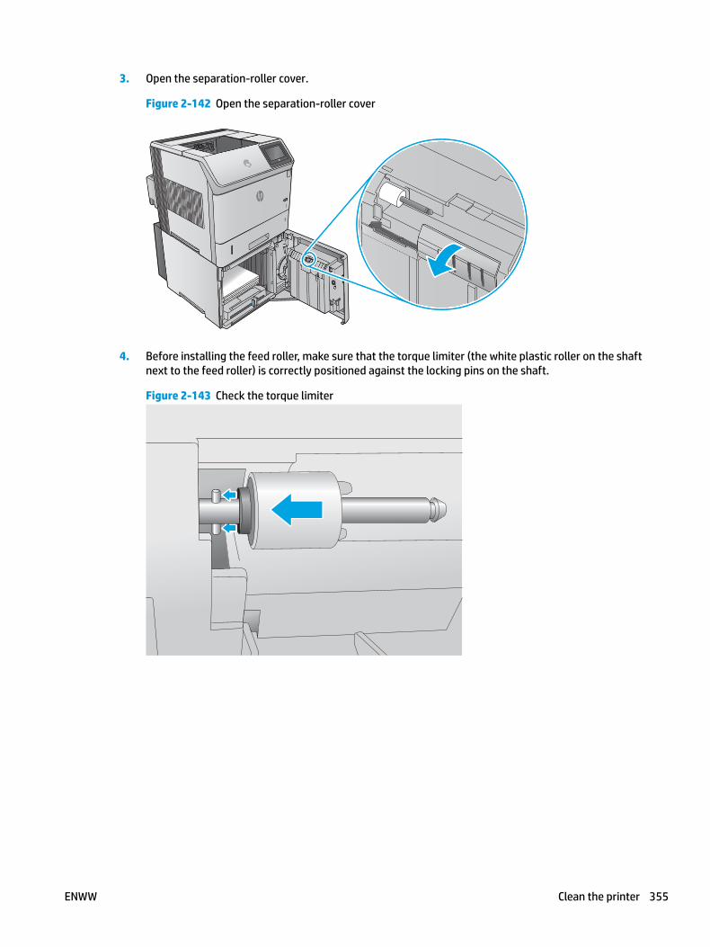
3. Open the separation-roller cover.
Figure 2-142 Open the separation-roller cover
4. Before installing the feed roller, make sure that the torque limiter (the white plastic roller on the shaft next to the feed roller) is correctly positioned against the locking pins on the shaft.
Figure 2-143 Check the torque limiter
ENWW Clean the printer 355
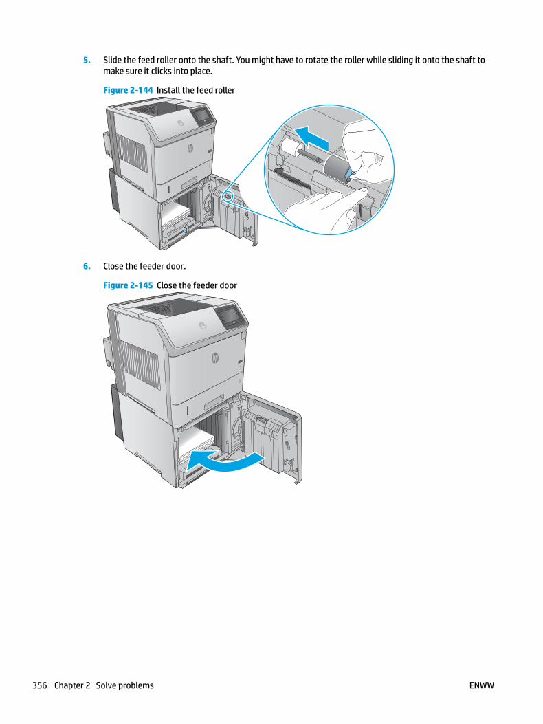
5. Slide the feed roller onto the shaft. You might have to rotate the roller while sliding it onto the shaft to make sure it clicks into place.
Figure 2-144 Install the feed roller
6. Close the feeder door.
Figure 2-145 Close the feeder door
356 Chapter 2 Solve problems ENWW
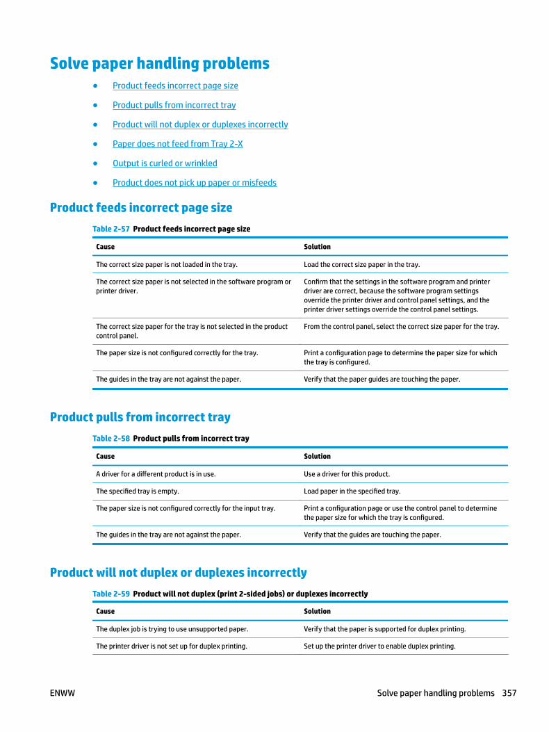
Solve paper handling problems● Product feeds incorrect page size
● Product pulls from incorrect tray
● Product will not duplex or duplexes incorrectly
● Paper does not feed from Tray 2-X
● Output is curled or wrinkled
● Product does not pick up paper or misfeeds
Product feeds incorrect page sizeTable 2-57 Product feeds incorrect page size
Cause Solution
The correct size paper is not loaded in the tray. Load the correct size paper in the tray.
The correct size paper is not selected in the software program or printer driver.
Confirm that the settings in the software program and printer driver are correct, because the software program settings override the printer driver and control panel settings, and the printer driver settings override the control panel settings.
The correct size paper for the tray is not selected in the product control panel.
From the control panel, select the correct size paper for the tray.
The paper size is not configured correctly for the tray. Print a configuration page to determine the paper size for which the tray is configured.
The guides in the tray are not against the paper. Verify that the paper guides are touching the paper.
Product pulls from incorrect trayTable 2-58 Product pulls from incorrect tray
Cause Solution
A driver for a different product is in use. Use a driver for this product.
The specified tray is empty. Load paper in the specified tray.
The paper size is not configured correctly for the input tray. Print a configuration page or use the control panel to determine the paper size for which the tray is configured.
The guides in the tray are not against the paper. Verify that the guides are touching the paper.
Product will not duplex or duplexes incorrectlyTable 2-59 Product will not duplex (print 2-sided jobs) or duplexes incorrectly
Cause Solution
The duplex job is trying to use unsupported paper. Verify that the paper is supported for duplex printing.
The printer driver is not set up for duplex printing. Set up the printer driver to enable duplex printing.
ENWW Solve paper handling problems 357
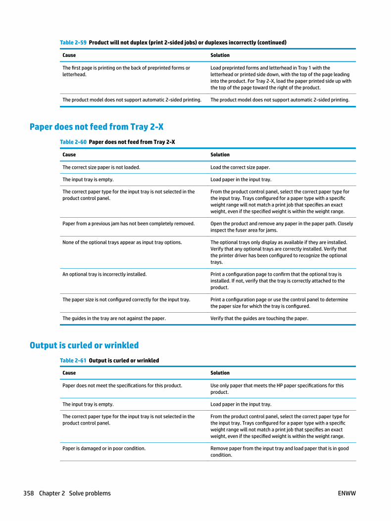
Table 2-59 Product will not duplex (print 2-sided jobs) or duplexes incorrectly (continued)
Cause Solution
The first page is printing on the back of preprinted forms or letterhead.
Load preprinted forms and letterhead in Tray 1 with the letterhead or printed side down, with the top of the page leading into the product. For Tray 2-X, load the paper printed side up with the top of the page toward the right of the product.
The product model does not support automatic 2-sided printing. The product model does not support automatic 2-sided printing.
Paper does not feed from Tray 2-XTable 2-60 Paper does not feed from Tray 2-X
Cause Solution
The correct size paper is not loaded. Load the correct size paper.
The input tray is empty. Load paper in the input tray.
The correct paper type for the input tray is not selected in the product control panel.
From the product control panel, select the correct paper type for the input tray. Trays configured for a paper type with a specific weight range will not match a print job that specifies an exact weight, even if the specified weight is within the weight range.
Paper from a previous jam has not been completely removed. Open the product and remove any paper in the paper path. Closely inspect the fuser area for jams.
None of the optional trays appear as input tray options. The optional trays only display as available if they are installed. Verify that any optional trays are correctly installed. Verify that the printer driver has been configured to recognize the optional trays.
An optional tray is incorrectly installed. Print a configuration page to confirm that the optional tray is installed. If not, verify that the tray is correctly attached to the product.
The paper size is not configured correctly for the input tray. Print a configuration page or use the control panel to determine the paper size for which the tray is configured.
The guides in the tray are not against the paper. Verify that the guides are touching the paper.
Output is curled or wrinkledTable 2-61 Output is curled or wrinkled
Cause Solution
Paper does not meet the specifications for this product. Use only paper that meets the HP paper specifications for this product.
The input tray is empty. Load paper in the input tray.
The correct paper type for the input tray is not selected in the product control panel.
From the product control panel, select the correct paper type for the input tray. Trays configured for a paper type with a specific weight range will not match a print job that specifies an exact weight, even if the specified weight is within the weight range.
Paper is damaged or in poor condition. Remove paper from the input tray and load paper that is in good condition.
358 Chapter 2 Solve problems ENWW

Table 2-61 Output is curled or wrinkled (continued)
Cause Solution
The product is operating in an excessively humid environment. Verify that the printing environment is within humidity specifications.
The print job consist of large, solid-filled areas. Large, solid-filled areas can cause excessive curl. Try using a different pattern.
Paper used was not stored correctly and might have absorbed moisture.
Remove paper and replace it with paper from a fresh, unopened package.
Paper has poorly cut edges. Remove paper, flex it, rotate it 180 degrees or turn it over, and then reload it into the input tray. Do not fan paper. If the problem persists, replace the paper.
The specific paper type was not configured for the tray or selected in the software.
Configure the software for the paper (see the software documentation). Configure the tray for the paper.
The paper has previously been used for a print job. Do not re-use paper.
Product does not pick up paper or misfeedsUse the following procedures if the product will not pick or misfeeds paper.
The product does not pick up paper
If the product does not pick up paper from the tray, try these solutions.
NOTE: Tray 1 and Tray 2 are optimal for paper pickup when using special paper or media other than 20lb plain paper. For Tray 1 and Tray 2 the product increases the number of attempts to pick up a page, which increases the reliability of successfully picking the page from the tray and decreases the possibility of a mispick jam.
HP recommends using Tray 1 or Tray 2 if the product is experiencing excessive or reoccurring jams from trays other than Tray 1 and Tray 2, or for print jobs that require media other than 20lb plain paper.
1. Open the product and remove any jammed sheets of paper.
2. Load the tray with the correct size of paper for the job.
3. Make sure the paper size and type are set correctly on the product control panel.
4. Make sure the paper guides in the tray are adjusted correctly for the size of paper. Adjust the guides to the appropriate indentation in the tray.
5. Check the product control panel to see if the product is waiting for an acknowledgment to the feed the paper manually prompt. Load paper, and continue.
6. The rollers above the tray might be contaminated. Clean the rollers with a lint-free cloth dampened with warm water.
ENWW Solve paper handling problems 359
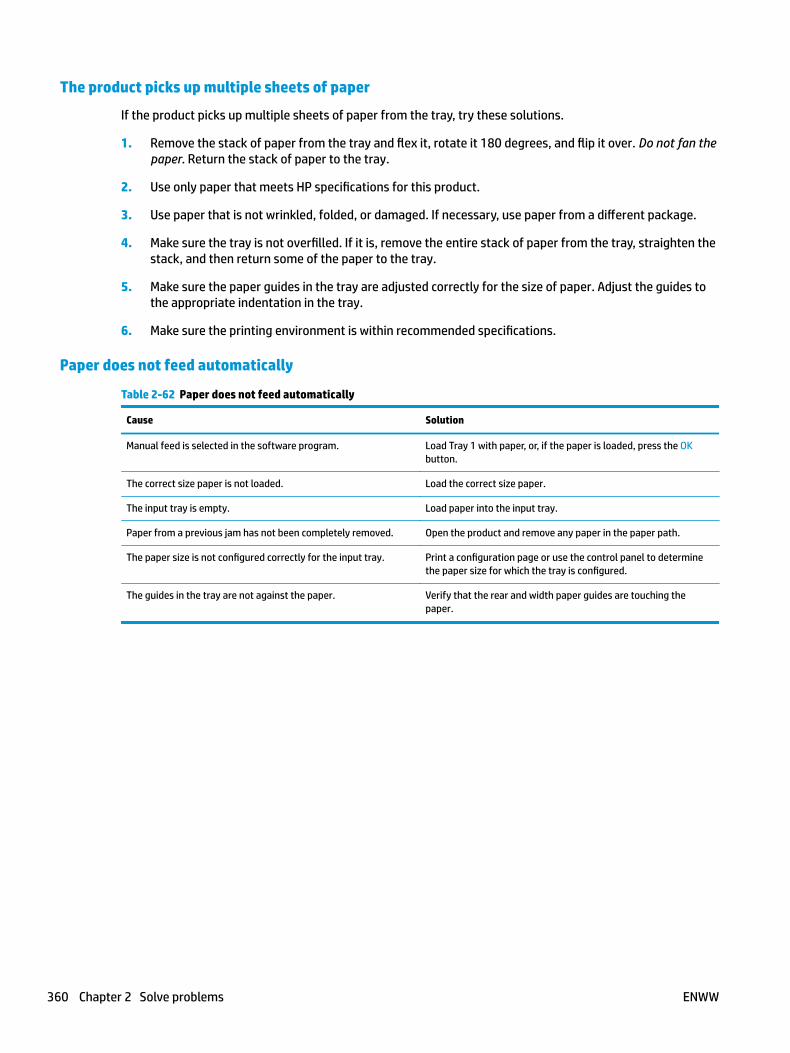
The product picks up multiple sheets of paper
If the product picks up multiple sheets of paper from the tray, try these solutions.
1. Remove the stack of paper from the tray and flex it, rotate it 180 degrees, and flip it over. Do not fan the paper. Return the stack of paper to the tray.
2. Use only paper that meets HP specifications for this product.
3. Use paper that is not wrinkled, folded, or damaged. If necessary, use paper from a different package.
4. Make sure the tray is not overfilled. If it is, remove the entire stack of paper from the tray, straighten the stack, and then return some of the paper to the tray.
5. Make sure the paper guides in the tray are adjusted correctly for the size of paper. Adjust the guides to the appropriate indentation in the tray.
6. Make sure the printing environment is within recommended specifications.
Paper does not feed automatically
Table 2-62 Paper does not feed automatically
Cause Solution
Manual feed is selected in the software program. Load Tray 1 with paper, or, if the paper is loaded, press the OK button.
The correct size paper is not loaded. Load the correct size paper.
The input tray is empty. Load paper into the input tray.
Paper from a previous jam has not been completely removed. Open the product and remove any paper in the paper path.
The paper size is not configured correctly for the input tray. Print a configuration page or use the control panel to determine the paper size for which the tray is configured.
The guides in the tray are not against the paper. Verify that the rear and width paper guides are touching the paper.
360 Chapter 2 Solve problems ENWW
Clear paper jams● Paper path jam sensor locations
● Auto-navigation for clearing jams
● Experiencing frequent or recurring paper jams?
● Clear paper jams in Tray 1
● Clear paper jams in Tray 2 and the 500-sheet trays
● Clear paper jams in the optional 1,500-sheet high-capacity tray
● Clear paper jams in the toner-cartridge area
● Clear paper jams in the rear output bin
● Clear paper jams in the fuser area
● Clear paper jams in the output bin
● Clear paper jams in the duplexer
● Clear paper jams in the envelope feeder
● Clear paper jams in the 5-bin mailbox
● Clear jams in the stacker or stapler/stacker
● Change jam recovery
ENWW Clear paper jams 361
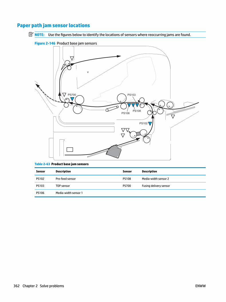
Paper path jam sensor locations
NOTE: Use the figures below to identify the locations of sensors where reoccurring jams are found.
Figure 2-146 Product base jam sensors
PS102
PS106PS108
PS103PS700
v
Table 2-63 Product base jam sensors
Sensor Description Sensor Description
PS102 Pre-feed sensor PS108 Media-width sensor 2
PS103 TOP sensor PS700 Fusing delivery sensor
PS106 Media-width sensor 1
362 Chapter 2 Solve problems ENWW
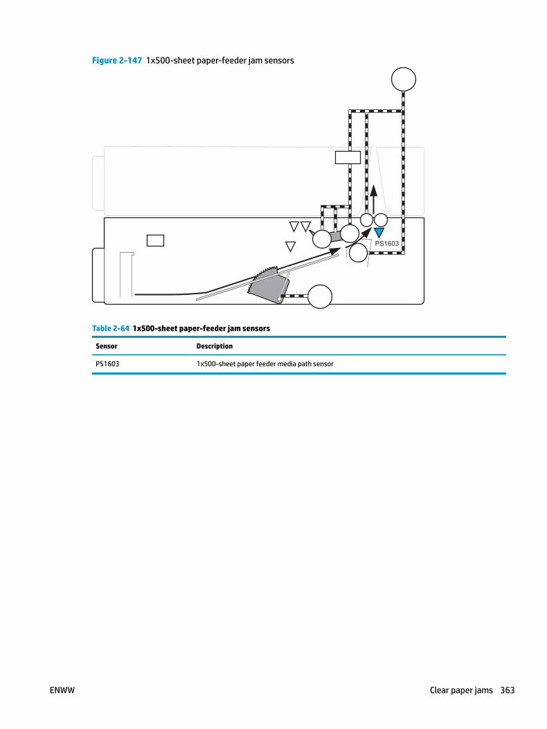
Figure 2-147 1x500-sheet paper-feeder jam sensors
PS1603
Table 2-64 1x500-sheet paper-feeder jam sensors
Sensor Description
PS1603 1x500-sheet paper feeder media path sensor
ENWW Clear paper jams 363
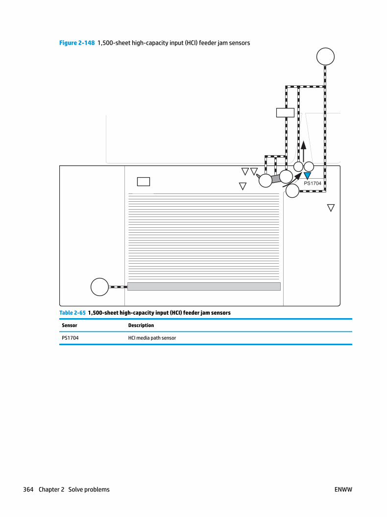
Figure 2-148 1,500-sheet high-capacity input (HCI) feeder jam sensors
PS1704
Table 2-65 1,500-sheet high-capacity input (HCI) feeder jam sensors
Sensor Description
PS1704 HCI media path sensor
364 Chapter 2 Solve problems ENWW
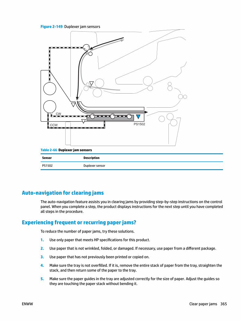
Figure 2-149 Duplexer jam sensors
PS1502
CW
CCW
Table 2-66 Duplexer jam sensors
Sensor Description
PS1502 Duplexer sensor
Auto-navigation for clearing jamsThe auto-navigation feature assists you in clearing jams by providing step-by-step instructions on the control panel. When you complete a step, the product displays instructions for the next step until you have completed all steps in the procedure.
Experiencing frequent or recurring paper jams?To reduce the number of paper jams, try these solutions.
1. Use only paper that meets HP specifications for this product.
2. Use paper that is not wrinkled, folded, or damaged. If necessary, use paper from a different package.
3. Use paper that has not previously been printed or copied on.
4. Make sure the tray is not overfilled. If it is, remove the entire stack of paper from the tray, straighten the stack, and then return some of the paper to the tray.
5. Make sure the paper guides in the tray are adjusted correctly for the size of paper. Adjust the guides so they are touching the paper stack without bending it.
ENWW Clear paper jams 365

6. Make sure that the tray is fully inserted in the product.
7. If you are printing on heavy, embossed, or perforated paper, use the manual feed feature and feed sheets one at a time.
8. Open the Trays menu on the product control panel. Verify that the tray is configured correctly for the paper type and size.
9. Make sure the printing environment is within recommended specifications.
366 Chapter 2 Solve problems ENWW
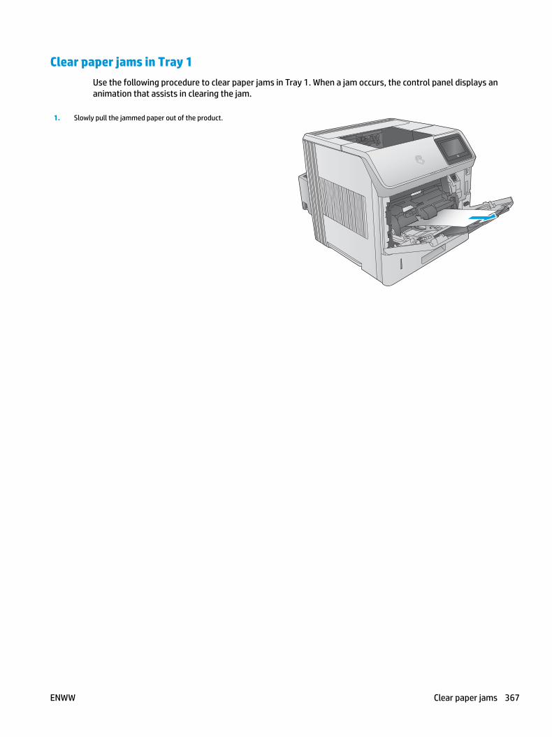
Clear paper jams in Tray 1Use the following procedure to clear paper jams in Tray 1. When a jam occurs, the control panel displays an animation that assists in clearing the jam.
1. Slowly pull the jammed paper out of the product.
ENWW Clear paper jams 367

Clear paper jams in Tray 2 and the 500-sheet traysUse the following procedure to check for paper in all possible jam locations related to Tray 2 and the 500-sheet trays. When a jam occurs, the control panel displays an animation that assists in clearing the jam.
1. Pull the tray completely out of the product by pulling and lifting it up slightly.
2. If the edge of the jammed paper is visible in the feed area, slowly pull the paper down and toward the back of the product. Then pull it out of the product. (Do not pull the paper straight out, or it will tear.) If the paper is not visible, look in the next tray or in the top-cover area.
368 Chapter 2 Solve problems ENWW
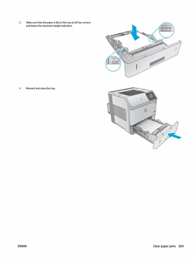
3. Make sure that the paper is flat in the tray at all four corners and below the maximum-height indicators.
2
4. Reinsert and close the tray.
ENWW Clear paper jams 369
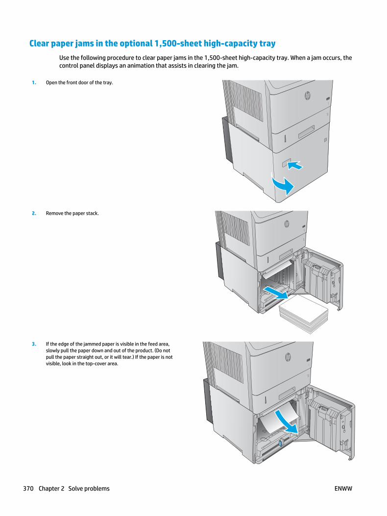
Clear paper jams in the optional 1,500-sheet high-capacity trayUse the following procedure to clear paper jams in the 1,500-sheet high-capacity tray. When a jam occurs, the control panel displays an animation that assists in clearing the jam.
1. Open the front door of the tray.
3
2. Remove the paper stack.
3. If the edge of the jammed paper is visible in the feed area, slowly pull the paper down and out of the product. (Do not pull the paper straight out, or it will tear.) If the paper is not visible, look in the top-cover area.
370 Chapter 2 Solve problems ENWW
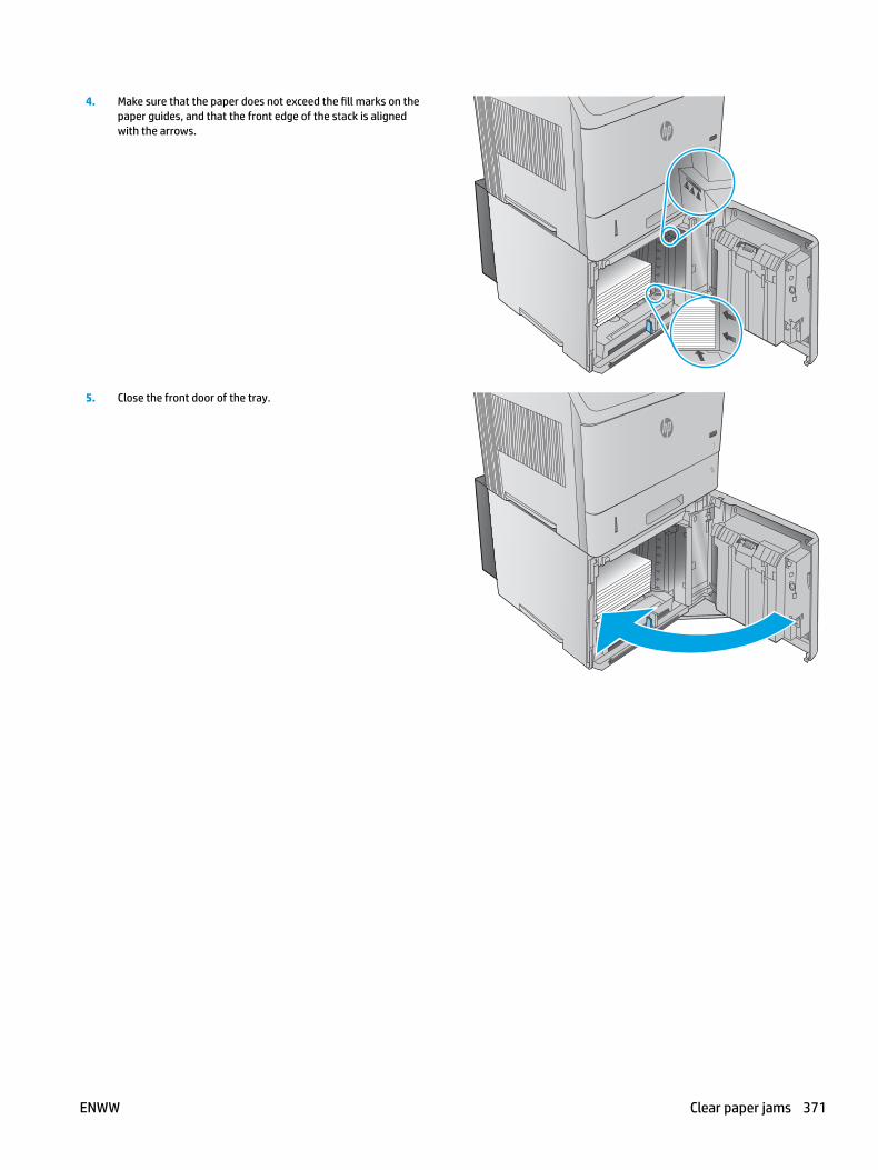
4. Make sure that the paper does not exceed the fill marks on the paper guides, and that the front edge of the stack is aligned with the arrows.
5. Close the front door of the tray.
ENWW Clear paper jams 371

Clear paper jams in the toner-cartridge areaUse the following procedure to check for paper in all possible jam locations in the toner-cartridge area. When a jam occurs, the control panel displays an animation that assists in clearing the jam.
1. Open the top cover.
2. Remove the toner cartridge.
CAUTION: To prevent damage to the toner cartridge, do not expose it to light for more than a few minutes. Cover the toner cartridge with a sheet of paper while it is outside of the product.
3. Use the green handle to lift the paper-access plate. Slowly pull the jammed paper out of the product. Do not tear the paper. If paper is difficult to remove, try clearing it from the tray area.
372 Chapter 2 Solve problems ENWW
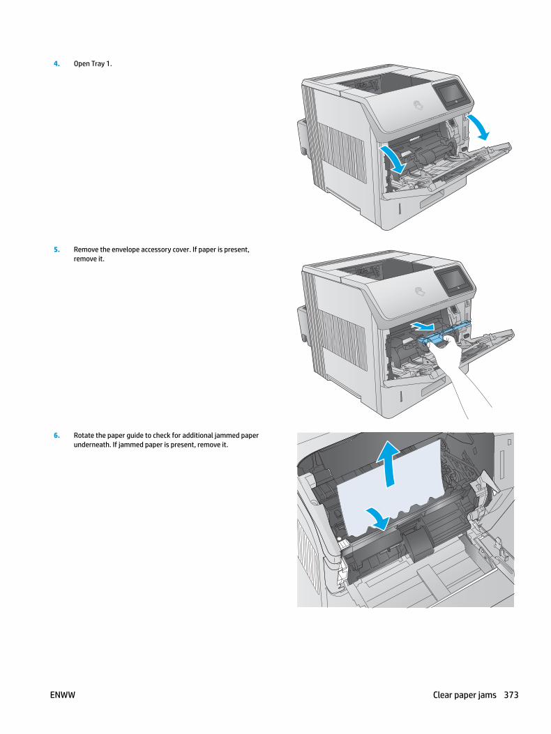
4. Open Tray 1.
5. Remove the envelope accessory cover. If paper is present, remove it.
6. Rotate the paper guide to check for additional jammed paper underneath. If jammed paper is present, remove it.
ENWW Clear paper jams 373
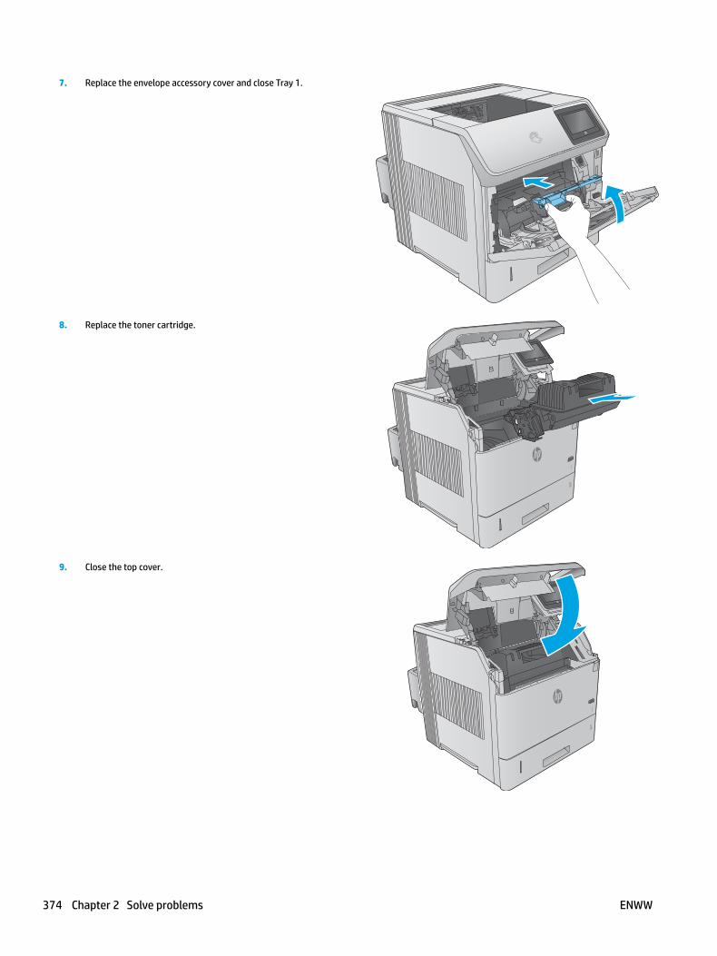
7. Replace the envelope accessory cover and close Tray 1.
8. Replace the toner cartridge.
9. Close the top cover.
374 Chapter 2 Solve problems ENWW
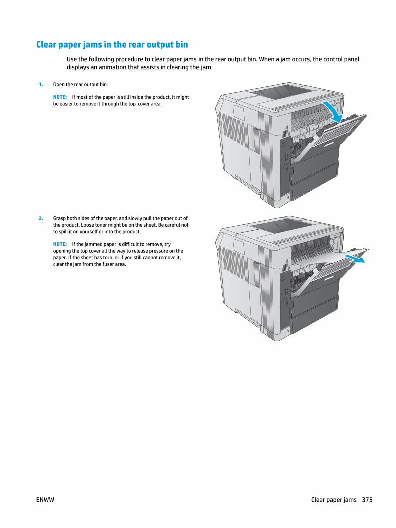
Clear paper jams in the rear output binUse the following procedure to clear paper jams in the rear output bin. When a jam occurs, the control panel displays an animation that assists in clearing the jam.
1. Open the rear output bin.
NOTE: If most of the paper is still inside the product, it might be easier to remove it through the top-cover area.
2. Grasp both sides of the paper, and slowly pull the paper out of the product. Loose toner might be on the sheet. Be careful not to spill it on yourself or into the product.
NOTE: If the jammed paper is difficult to remove, try opening the top cover all the way to release pressure on the paper. If the sheet has torn, or if you still cannot remove it, clear the jam from the fuser area.
ENWW Clear paper jams 375

Clear paper jams in the fuser areaUse the following procedure to check for paper in all possible jam locations in the fuser area. When a jam occurs, the control panel displays an animation that assists in clearing the jam.
Use this procedure only in these situations:
● Paper has jammed inside the fuser and cannot be removed from the top-cover area or the rear output area.
● A sheet of paper tears during an attempt to clear a jam from the fuser.
1. Turn the product off.
2. Disconnect the power cord.
376 Chapter 2 Solve problems ENWW
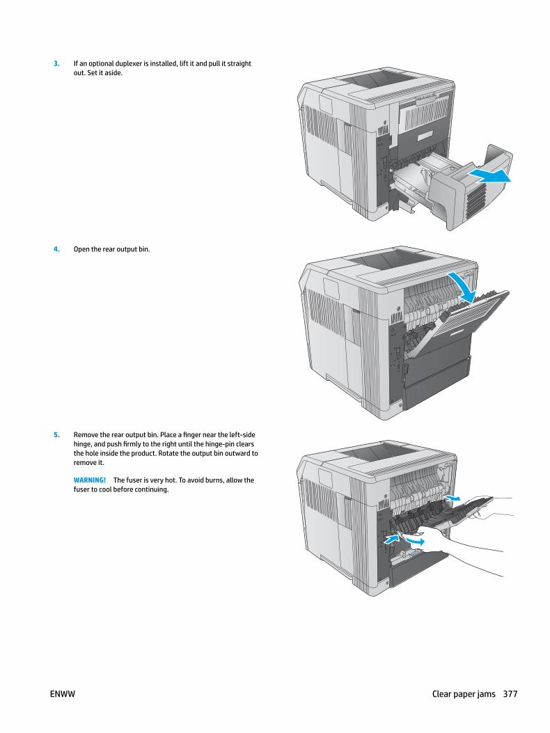
3. If an optional duplexer is installed, lift it and pull it straight out. Set it aside.
4. Open the rear output bin.
5. Remove the rear output bin. Place a finger near the left-side hinge, and push firmly to the right until the hinge-pin clears the hole inside the product. Rotate the output bin outward to remove it.
WARNING! The fuser is very hot. To avoid burns, allow the fuser to cool before continuing.
ENWW Clear paper jams 377

6. Push up on the two blue levers on the sides of the fuser to release it, and then pull the fuser straight out of the product to remove it..
7. Remove the jammed paper. If necessary, lift the black plastic guide that is located on the top of the fuser to gain access to the jammed sheet.
CAUTION: Do not use a sharp or metal object to clear paper from the fuser area. It might damage the fuser.
8. Push the fuser straight into the product until it snaps into place.
378 Chapter 2 Solve problems ENWW
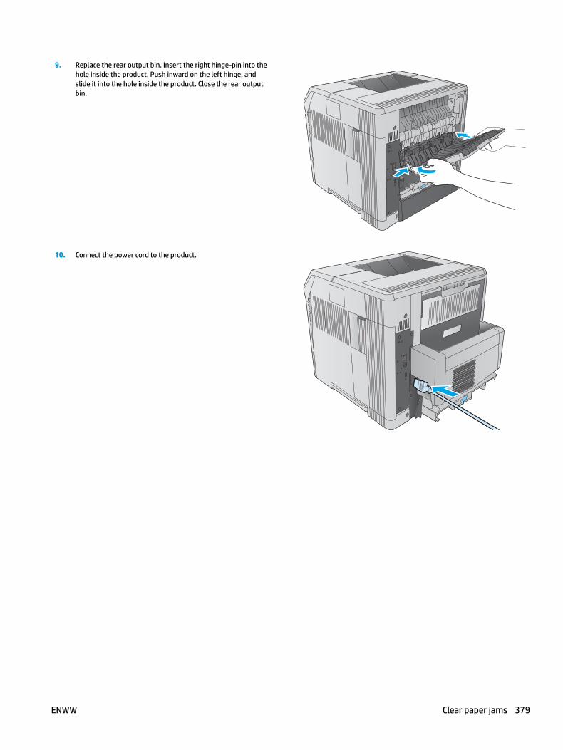
9. Replace the rear output bin. Insert the right hinge-pin into the hole inside the product. Push inward on the left hinge, and slide it into the hole inside the product. Close the rear output bin.
10. Connect the power cord to the product.
ENWW Clear paper jams 379

11. Replace the optional duplexer, if it was removed.
12. Turn the product on.
380 Chapter 2 Solve problems ENWW

Clear paper jams in the output binUse the following procedure to check for paper in all possible jam locations in the output bin. When a jam occurs, the control panel displays an animation that assists in clearing the jam.
1. If paper is visible in the output bin, grasp the leading edge and remove it.
ENWW Clear paper jams 381
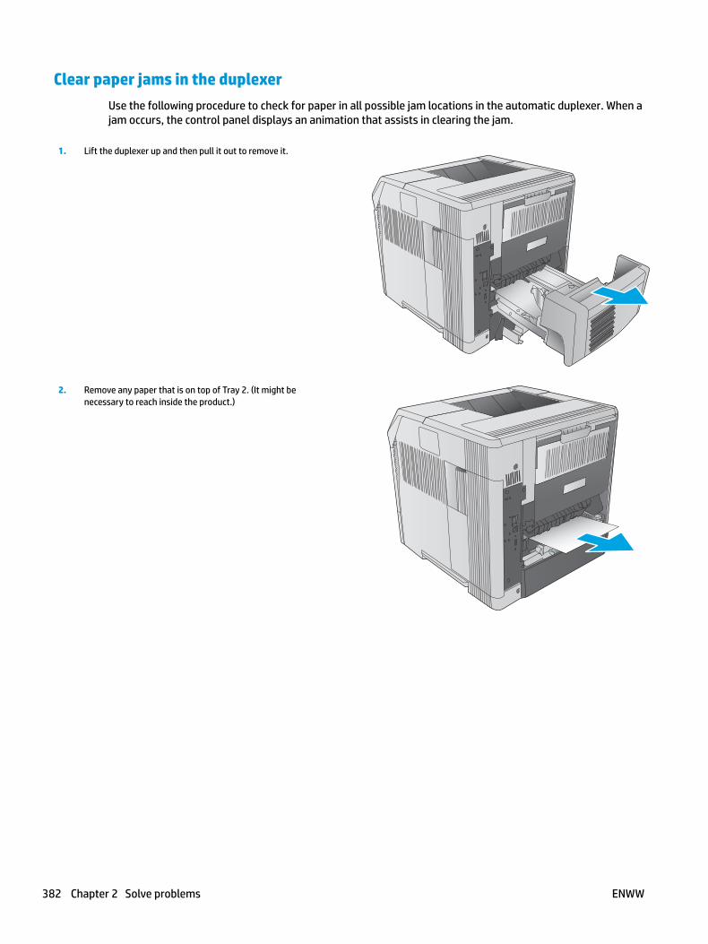
Clear paper jams in the duplexerUse the following procedure to check for paper in all possible jam locations in the automatic duplexer. When a jam occurs, the control panel displays an animation that assists in clearing the jam.
1. Lift the duplexer up and then pull it out to remove it.
2. Remove any paper that is on top of Tray 2. (It might be necessary to reach inside the product.)
382 Chapter 2 Solve problems ENWW
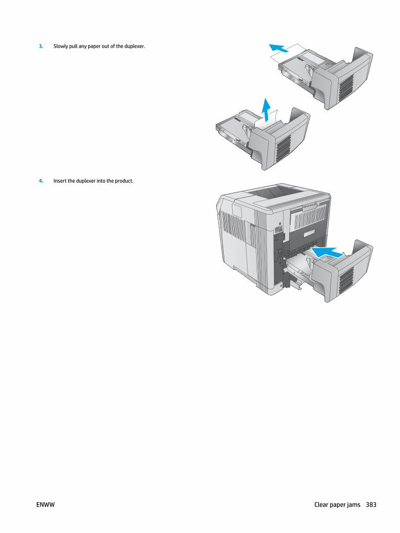
3. Slowly pull any paper out of the duplexer.
4. Insert the duplexer into the product.
ENWW Clear paper jams 383
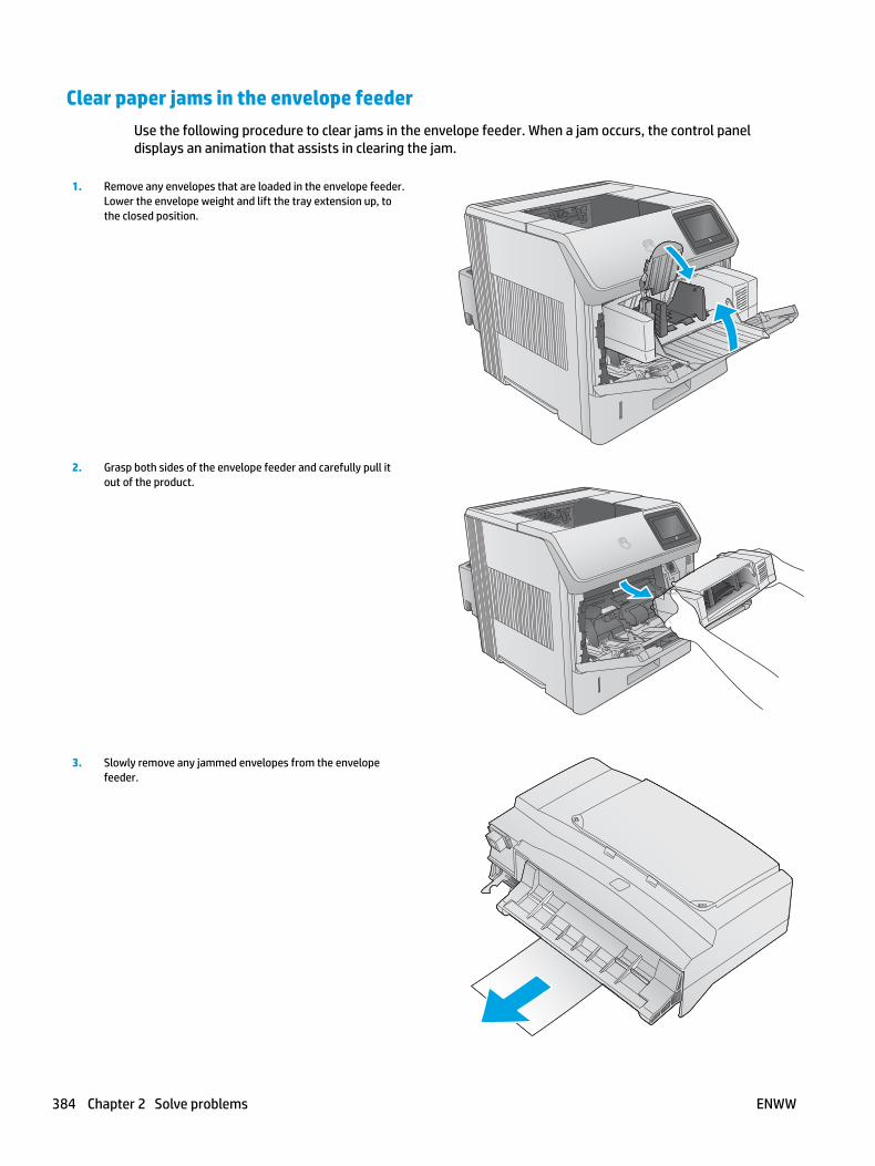
Clear paper jams in the envelope feederUse the following procedure to clear jams in the envelope feeder. When a jam occurs, the control panel displays an animation that assists in clearing the jam.
1. Remove any envelopes that are loaded in the envelope feeder. Lower the envelope weight and lift the tray extension up, to the closed position.
2. Grasp both sides of the envelope feeder and carefully pull it out of the product.
3. Slowly remove any jammed envelopes from the envelope feeder.
384 Chapter 2 Solve problems ENWW
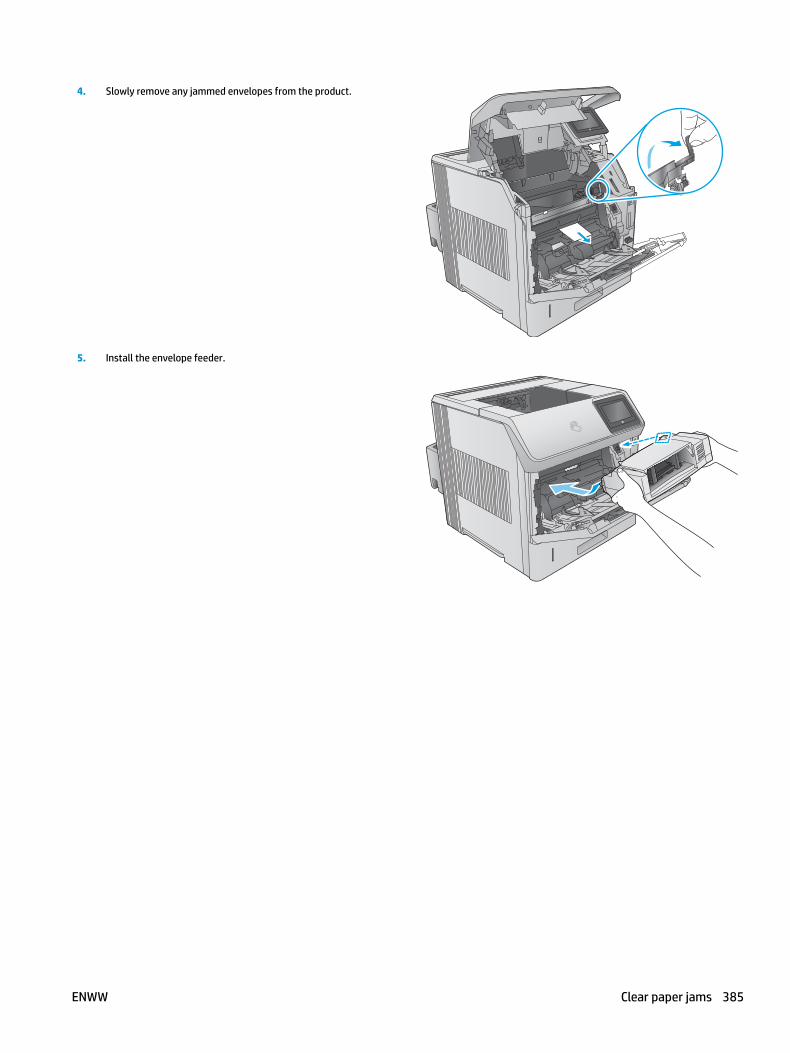
4. Slowly remove any jammed envelopes from the product.
5. Install the envelope feeder.
ENWW Clear paper jams 385

Clear paper jams in the 5-bin mailboxUse the following procedure to check for paper in all possible jam locations in the 5-bin mailbox. When a jam occurs, the control panel displays an animation that assists in clearing the jam.
1. Remove any paper from the output bins.
2. On the back of the 5-bin mailbox, open the jam-access door.
386 Chapter 2 Solve problems ENWW

3. If the paper is jammed at the top of the 5-bin mailbox, pull it straight down to remove it.
4. If the paper is jammed at the bottom of the 5-bin mailbox, open the rear output bin, and then pull straight up on the paper to remove it.
5. Close the jam-access door and the rear output bin.
ENWW Clear paper jams 387
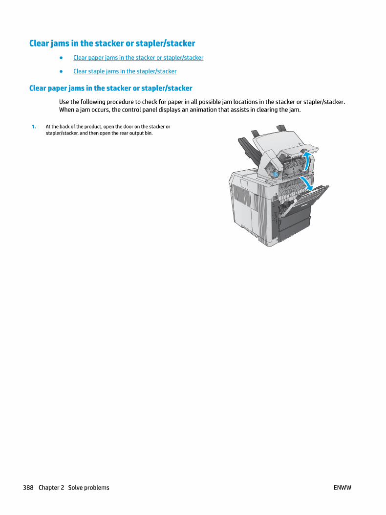
Clear jams in the stacker or stapler/stacker● Clear paper jams in the stacker or stapler/stacker
● Clear staple jams in the stapler/stacker
Clear paper jams in the stacker or stapler/stacker
Use the following procedure to check for paper in all possible jam locations in the stacker or stapler/stacker. When a jam occurs, the control panel displays an animation that assists in clearing the jam.
1. At the back of the product, open the door on the stacker or stapler/stacker, and then open the rear output bin.
388 Chapter 2 Solve problems ENWW

2. Carefully remove any jammed paper.
3. Close the door on the stacker or stapler/stacker, and close the rear output bin.
NOTE: The output bin must be pushed down into the lowest position for printing to continue.
Clear staple jams in the stapler/stacker
Use the following procedure to clear staple jams in the stapler/stacker. When a jam occurs, the control panel displays an animation that assists in clearing the jam.
The stapler needs to reload after clearing a staple jam, so the first few documents might not be stapled. If a print job is sent and the stapler is jammed or is out of staples, the job will still print as long as the path to the stacker bin is not blocked.
ENWW Clear paper jams 389

1. On the right side of the stapler/stacker, turn the stapler unit toward the front of the product until the unit clicks into the open position. Pull outward on the blue staple cartridge to remove it.
2. Rotate the green cover on the end of the staple cartridge upward, and remove the jammed staple.
3. Insert the staple cartridge into the stapler unit, and rotate the stapler unit toward the rear of the product until the unit snaps into place.
390 Chapter 2 Solve problems ENWW

Change jam recoveryThis printer provides a jam recovery feature that reprints jammed pages.
Change jam recovery from a touchscreen control panel
1. From the Home screen on the printer control panel, scroll to and touch the Administration button.
2. Open the General Settings menu, and then open the Jam Recovery menu.
3. Select one of the following options:
● Automatic — The printer attempts to reprint jammed pages when sufficient memory is available. This is the default setting.
● Off — The printer does not attempt to reprint jammed pages. Because no memory is used to store the most recent pages, performance is optimal.
NOTE: Some pages can be lost if the printer runs out of paper while printing a duplex job with Jam Recovery set to Off.
● On — The printer always reprints jammed pages. Additional memory is allocated to store the last few pages printed.
Change jam recovery from a LCD control panel
1. From the Home screen on the printer control panel, use the down arrow button to scroll to Administration, and then press the OK button.
2. Use the down arrow button to scroll to General Settings, and then press the OK button.
3. Use the down arrow button to scroll to Jam Recovery, and then press the OK button.
4. Use the down arrow button to scroll to an option, and then press the OK button to select it.
● Automatic — The printer attempts to reprint jammed pages when sufficient memory is available. This is the default setting.
● Off — The printer does not attempt to reprint jammed pages. Because no memory is used to store the most recent pages, performance is optimal.
NOTE: Some pages can be lost if the printer runs out of paper while printing a duplex job with Jam Recovery set to Off.
● On — The printer always reprints jammed pages. Additional memory is allocated to store the last few pages printed.
ENWW Clear paper jams 391
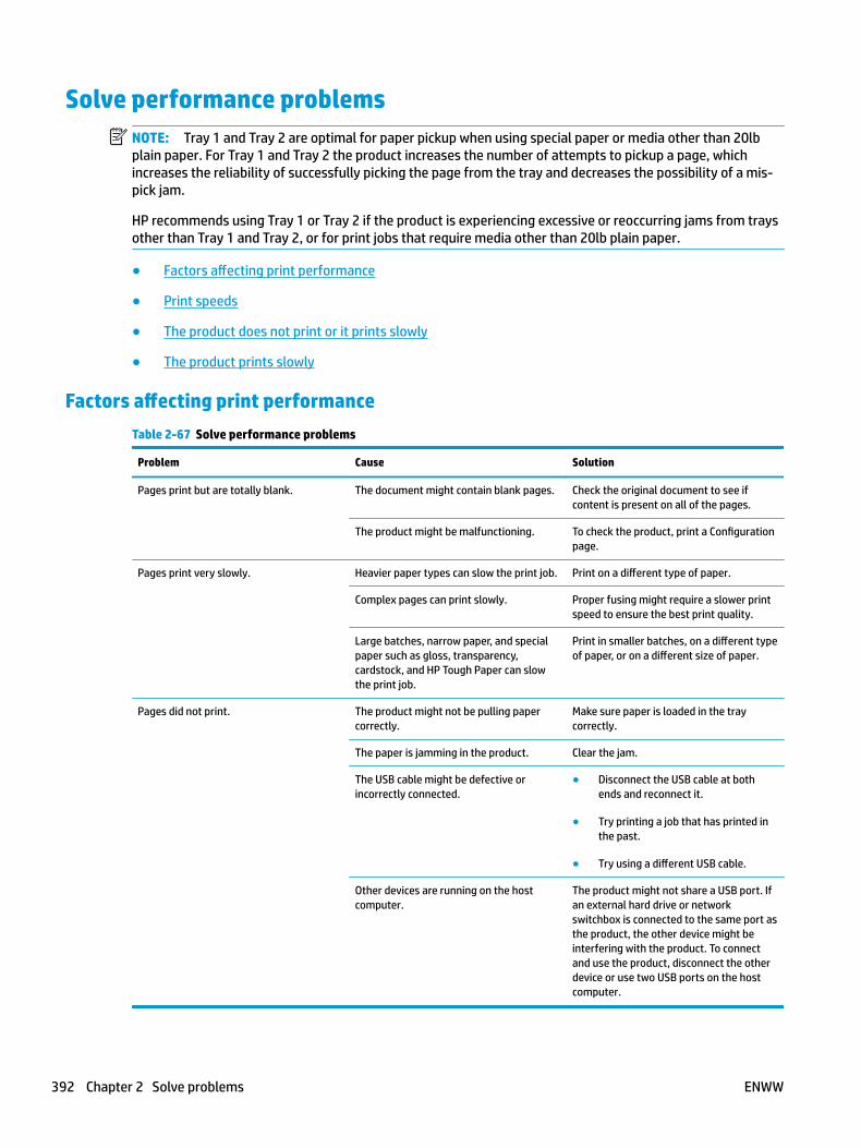
Solve performance problemsNOTE: Tray 1 and Tray 2 are optimal for paper pickup when using special paper or media other than 20lb plain paper. For Tray 1 and Tray 2 the product increases the number of attempts to pickup a page, which increases the reliability of successfully picking the page from the tray and decreases the possibility of a mis-pick jam.
HP recommends using Tray 1 or Tray 2 if the product is experiencing excessive or reoccurring jams from trays other than Tray 1 and Tray 2, or for print jobs that require media other than 20lb plain paper.
● Factors affecting print performance
● Print speeds
● The product does not print or it prints slowly
● The product prints slowly
Factors affecting print performanceTable 2-67 Solve performance problems
Problem Cause Solution
Pages print but are totally blank. The document might contain blank pages. Check the original document to see if content is present on all of the pages.
The product might be malfunctioning. To check the product, print a Configuration page.
Pages print very slowly. Heavier paper types can slow the print job. Print on a different type of paper.
Complex pages can print slowly. Proper fusing might require a slower print speed to ensure the best print quality.
Large batches, narrow paper, and special paper such as gloss, transparency, cardstock, and HP Tough Paper can slow the print job.
Print in smaller batches, on a different type of paper, or on a different size of paper.
Pages did not print. The product might not be pulling paper correctly.
Make sure paper is loaded in the tray correctly.
The paper is jamming in the product. Clear the jam.
The USB cable might be defective or incorrectly connected.
● Disconnect the USB cable at both ends and reconnect it.
● Try printing a job that has printed in the past.
● Try using a different USB cable.
Other devices are running on the host computer.
The product might not share a USB port. If an external hard drive or network switchbox is connected to the same port as the product, the other device might be interfering with the product. To connect and use the product, disconnect the other device or use two USB ports on the host computer.
392 Chapter 2 Solve problems ENWW
Print speedsPrint speed is the number of pages that print in one minute. Print speed depends on different engine-process speeds or operational pauses between printed pages during normal product operation. Factors that determine the print speed of the product include the following:
● Page formatting time
The product must pause for each page to be formatted before it prints. Complex pages take more time to format, resulting in reduced print speed. However, most jobs print at full engine speed.
● Media size
Legal-size media reduces print speed because it is longer than the standard Letter- or A4–size media. A reduce print speed is used when printing on narrow media to prevent the edges of the fuser from overheating.
● Media mode
Some media types require a reduced print speed to achieve maximum print quality on that media. For example, glossy, heavy, and specialty media (for example, envelopes or photos) require a reduced print speed. To maximize the print speed for special media types, make sure that the correct media type in the print driver is selected.
● Product temperature
To prevent product damage, print speed is reduced if the product reaches a specific internal temperature (thermal slow down). The starting temperature of the product, ambient environment temperature, and the print job size effect the number of pages that can be printed before the product reduces the print speed. Thermal slow down reduces print speed by printing four pages and then pausing for an amount of time before printing continues.
● Other print speed reduction factors
Other factors (especially during large print jobs) that can cause reduced print speeds include:
◦ Density control sequence; occurs every 150 pages and takes about 120 seconds
The product does not print or it prints slowly
The product does not print
If the product does not print at all, try the following solutions.
1. Make sure the product is turned on and that the control panel indicates it is ready.
● If the control panel does not indicate the product is ready, turn the product off and then on again.
● If the control panel indicates the product is ready, try sending the job again.
2. If the control panel indicates the product has an error, resolve the error and then try sending the job again.
3. Make sure the cables are all connected correctly. If the product is connected to a network, check the following items:
ENWW Solve performance problems 393

● Check the bottom LED next to the network connection on the product. If the network is active, the light is green.
● Make sure that a network cable and not a phone cord is used to connect to the network.
● Make sure the network router, hub, or switch is turned on and that it is working correctly.
4. Install the HP software from the CD that came with the product. Using generic printer drivers can cause delays clearing jobs from the print queue.
5. From the list of printers on your computer, right-click the name of this product, click Properties, and open the Ports tab.
● If a network cable is used to connect to the network, make sure the printer name listed on the Ports tab matches the product name on the product configuration page.
● If a USB cable is used, and the product is connected to a wireless network, make sure the box is checked next to Virtual printer port for USB.
6. If a personal firewall system on the computer is used, it might be blocking communication with the product. Try temporarily disabling the firewall to see if it is the source of the problem.
7. If the host computer or the product is connected to a wireless network, low signal quality or interference might be delaying print jobs.
The product prints slowly
The product prints slowly
If the product prints, but it seems slow, try the following solutions.
1. Make sure the computer meets the minimum specifications for this product. For a list of specifications, go to this Web site: www.hp.com/support/ljM604, www.hp.com/support/ljM605, www.hp.com/support/ljM606.
2. When the product is configured to print on some paper types, such as heavy paper, the product prints more slowly so it can correctly fuse the toner to the paper. If the paper type setting is not correct for the type of paper you are using, change the setting to the correct paper type.
3. If the host computer or the product is connected to a wireless network, low signal quality or interference might be delaying print jobs.
394 Chapter 2 Solve problems ENWW

Solve connectivity problems● Solve USB connection problems
● Solve wired network problems
Solve USB connection problemsIf you have connected the product directly to a computer, check the cable.
● Verify that the cable is connected to the computer and to the product.
● Verify that the cable is not longer than 2 m (6.65 ft). Try using a shorter cable.
● Verify that the cable is working correctly by connecting it to another product. Replace the cable if necessary.
Solve wired network problemsCheck the following items to verify that the product is communicating with the network. Before beginning, print a configuration page from the product control panel and locate the product IP address that is listed on this page.
● Poor physical connection
● The computer is using the incorrect IP address for the product
● The computer is unable to communicate with the product
● The product is using incorrect link and duplex settings for the network
● New software programs might be causing compatibility problems
● The computer or workstation might be set up incorrectly
● The product is disabled, or other network settings are incorrect
NOTE: HP does not support peer-to-peer networking, as the feature is a function of Microsoft operating systems and not of the HP print drivers. For more information, go to Microsoft at www.microsoft.com.
Poor physical connection
1. Verify that the product is attached to the correct network port using a cable of the correct length.
2. Verify that cable connections are secure.
3. Look at the network port connection on the back of the product, and verify that the amber activity light and the green link-status light are lit.
4. If the problem continues, try a different cable or port on the hub.
The computer is using the incorrect IP address for the product
1. Open the printer properties and click the Ports tab. Verify that the current IP address for the product is selected. The product IP address is listed on the product configuration page.
2. If you installed the product using the HP standard TCP/IP port, select the box labeled Always print to this printer, even if its IP address changes.
ENWW Solve connectivity problems 395

3. If you installed the product using a Microsoft standard TCP/IP port, use the hostname instead of the IP address.
4. If the IP address is correct, delete the product and then add it again.
The computer is unable to communicate with the product
1. Test network communication by pinging the network.
a. Open a command-line prompt on your computer. For Windows, click Start, click Run, type cmd, and then press Enter.
b. Type ping followed by the IP address for your product.
For Mac OS X, open the Network Utility, and then supply the IP address in the correct field in the Ping pane.
c. If the window displays round-trip times, the network is working.
2. If the ping command failed, verify that the network hubs are on, and then verify that the network settings, the product, and the computer are all configured for the same network.
The product is using incorrect link and duplex settings for the network
Hewlett-Packard recommends leaving these settings in automatic mode (the default setting). If you change these settings, you must also change them for your network.
New software programs might be causing compatibility problems
Verify that any new software programs are correctly installed and that they use the correct print driver.
The computer or workstation might be set up incorrectly
1. Check the network drivers, print drivers, and the network redirection settings.
2. Verify that the operating system is configured correctly.
The product is disabled, or other network settings are incorrect
1. Review the configuration page to check the status of the network protocol. Enable it if necessary.
2. Reconfigure the network settings if necessary.
396 Chapter 2 Solve problems ENWW
Service mode functions● Service menu
● Product resets
● Format Disk and Partial Clean functions
Service menuThe Service menu is PIN-protected for added security. Only authorized service people have access to the Service menu. When selecting Service from the list of menus, the product prompts the user to enter an eight-digit personal identification number (PIN).
NOTE: The product automatically exits the Service menu after about one minute if no items are selected or changed.
Open the service menu from a touchscreen control panel
1. From the Home screen on the product control panel, scroll to and touch the Device Maintenance button.
2. Open the Service menu.
3. On the sign-in screen, select Service Access Code from the drop-down list.
4. Enter the following service access code for the product:
● 04060415
● 04060515
● 04060615
Open the service menu from a LCD control panel
1. From the Home screen on the product control panel, use the down arrow button to scroll to Device Maintenance, and then press the OK button.
2. Use the down arrow button to scroll to Service, and then press the OK button to select it.
3. Use the down arrow button to scroll to Service Access Code, and then press the OK button to select it.
4. Enter the following service access code for the product:
NOTE: After entering the PIN, press the OK button.
● 04060415
● 04060515
● 04060615
The following menu items appear in the Service menu:
First level Second level Value Description
Event Log Print Print the event log.
ENWW Service mode functions 397

First level Second level Value Description
Clear Event Log Clear Use this item to clear the product event log.
Cycle Counts Total Engine Cycles Set the page count that was stored in NVRAM prior to installing a new formatter.
Refurbish Cycle Count Use this item to record the page count when the product was refurbished.
Serial Number Set the serial number.
Service ID Use this item to show the date that the product was first used on the control panel. This eliminates the need for users to keep paper receipts for proof of warranty.
Cold Reset Paper When you perform a cold reset, the paper size that is stored in NVRAM is reset to the default factory setting. If you replace a formatter board in a country/region that uses A4 as the standard paper size, use this menu to reset the default paper size to A4. LETTER and A4 are the only available values.
Low Alerts Enable
Disable
Turn on (or off) low alerts (for supplies).
Reset Low Alerts ● Reset to level 1
● Reset to level 2
● Reset to level 3
● Set to non-HP managed mode
Test Support Continuous Print from USB
Product resets
Restore factory-set defaults
NOTE: The product restarts automatically after the reset operation completes.
Restore factory-set defaults from a touchscreen control panel
1. From the Home screen on the product control panel, scroll to and touch the Administration button.
2. Open the following menus:
398 Chapter 2 Solve problems ENWW
● General Settings
● Restore Factory Settings
3. A verification message advises that completing the reset function might result in loss of data. Touch the Reset button to complete the process.
Restore factory-set defaults from a LCD control panel
1. From the Home screen on the product control panel, use the down arrow button to scroll to Administration, and then press the OK button.
2. Use the down arrow button to scroll to General Settings, and then press the OK button to select it.
3. Use the down arrow button to scroll to Restore Factory Settings, and then press the OK button to select it.
4. Use the down arrow button to scroll to Restore, and then press the OK button to select it.
5. A verification message advises that completing the reset function might result in loss of data. Touch the Reset button to complete the process.
Restore the service ID
Restore the service ID
When replacing the formatter, the date is lost. Use this menu item to reset the date to the original date that the product was first used. The date format is YYDDD. Use the following formula to calculate the dates:
1. To calculate YY, subtract 1990 from the calendar year. For instance, if the product was first used in 2002, calculate YY as follows: 2002 - 1990 = 12. YY = 12.
2. Subtract 1 from 10 (October is the tenth month of the year): 10 - 1 = 9.
● Multiply 9 by 30: 9 x 30 = 270 or add 17 to 270: 270 + 17 = 287. Thus, DDD = 287.
Convert the service ID to an actual date
Use the product Service ID number to determine whether the product is still under warranty. Use the following formula to convert the Service ID into the installation date as follows:
1. Add 1990 to YY to get the actual year that the product was installed.
2. Divide DDD by 30. If there is a remainder, add 1 to the result. This is the month.
3. The remainder from the calculation in step 2 is the date.
Using the Service ID 12287 as an example, the date conversion is as follows:
1. 12 + 1990 = 2002, so the year is 2002.
2. 287 divided by 30 = 9 with a remainder of 17. Because there is a remainder, add 1 to 9 to get 10, which represents October.
3. The remainder in step 2 is 17, so that is the date.
4. The complete date is 17-October-2002.
NOTE: A six-day grace period is built into the date system.
ENWW Service mode functions 399
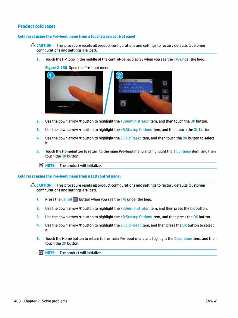
Product cold reset
Cold reset using the Pre-boot menu from a touchscreen control panel
CAUTION: This procedure resets all product configurations and settings to factory defaults (customer configurations and settings are lost).
1. Touch the HP logo in the middle of the control-panel display when you see the 1/8 under the logo.
Figure 2-150 Open the Pre-boot menu
1 2
2. Use the down arrow button to highlight the +3:Administrator item, and then touch the OK button.
3. Use the down arrow button to highlight the +8:Startup Options item, and then touch the OK button.
4. Use the down arrow button to highlight the 2 Cold Reset item, and then touch the OK button to select it.
5. Touch the Homebutton to return to the main Pre-boot menu and highlight the 1:Continue item, and then touch the OK button.
NOTE: The product will initialize.
Cold reset using the Pre-boot menu from a LCD control panel
CAUTION: This procedure resets all product configurations and settings to factory defaults (customer configurations and settings are lost).
1. Press the Cancel button when you see the 1/8 under the logo.
2. Use the down arrow button to highlight the +3:Administrator item, and then press the OK button.
3. Use the down arrow button to highlight the +8:Startup Options item, and then press the OK button.
4. Use the down arrow button to highlight the 2 Cold Reset item, and then press the OK button to select it.
5. Touch the Home button to return to the main Pre-boot menu and highlight the 1:Continue item, and then touch the OK button.
NOTE: The product will initialize.
400 Chapter 2 Solve problems ENWW
Format Disk and Partial Clean functions
NOTE: Only for products with an optional hard-disk drive (HDD) installed).
Active and repository firmware locations
The firmware bundle consists of multiple parts. The main components are the Windows CE Operating System and the product/peripheral firmware files.
There are two locations/partitions on the hard drive where the firmware components are stored:
● The Active, where the operating system and firmware currently are executing.
● The Repository, the recovery location.
If the Active location is damaged, or a Partial Clean was performed, the product automatically copies over the OS and firmware files from the Repository location and the product recovers.
If both the Active and Repository locations are damaged, or a Format Disk was performed, then both locations are gone and the error message 99.09.67 displays on the control-panel display. The user must upload the firmware to the product in order for it to function again.
CAUTION: The Format Disk option performs a disk initialization for the entire disk. The operating system, firmware files, and third party files (among other files) will be completely lost. HP does not recommend this action.
Partial Clean
The Partial Clean option erases all partitions and data on the disk drive, except for the firmware repository where a backup copy of the firmware file is stored. This allows the disk drive to be reformatted without having to download a firmware upgrade file to return the product to a bootable state.
Characteristics of a Partial Clean
● Customer-defined settings, third-party solutions, firmware files, and the operating system are deleted.
● Rebooting the product restores the firmware files from the Repository location, but does not restore any customer-defined settings.
● For previous HP products, a Hard Disk Initialization is similar to executing the Partial Clean function for this product.
CAUTION: HP recommends backing-up product configuration data before executing a Partial Clean to retain customer-defined settings (if needed). See the Backup/Restore item in the Device Maintenance menu.
Reasons for performing Partial Clean
● The product continually boots up in an error state.
NOTE: Try clearing the error prior to executing a Partial Clean.
● The product will not respond to commands from the control panel.
● Executing the Partial Clean function is helpful for troubleshooting hard disk problems.
ENWW Service mode functions 401
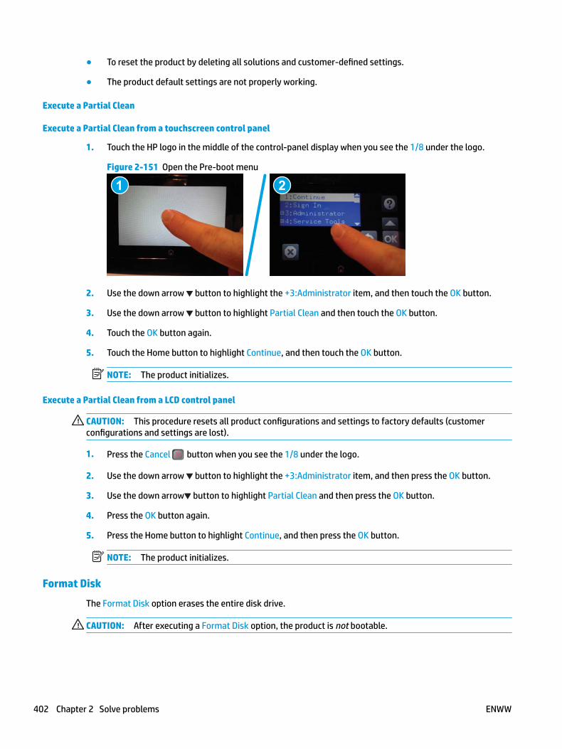
● To reset the product by deleting all solutions and customer-defined settings.
● The product default settings are not properly working.
Execute a Partial Clean
Execute a Partial Clean from a touchscreen control panel
1. Touch the HP logo in the middle of the control-panel display when you see the 1/8 under the logo.
Figure 2-151 Open the Pre-boot menu
1 2
2. Use the down arrow button to highlight the +3:Administrator item, and then touch the OK button.
3. Use the down arrow button to highlight Partial Clean and then touch the OK button.
4. Touch the OK button again.
5. Touch the Home button to highlight Continue, and then touch the OK button.
NOTE: The product initializes.
Execute a Partial Clean from a LCD control panel
CAUTION: This procedure resets all product configurations and settings to factory defaults (customer configurations and settings are lost).
1. Press the Cancel button when you see the 1/8 under the logo.
2. Use the down arrow button to highlight the +3:Administrator item, and then press the OK button.
3. Use the down arrow button to highlight Partial Clean and then press the OK button.
4. Press the OK button again.
5. Press the Home button to highlight Continue, and then press the OK button.
NOTE: The product initializes.
Format Disk
The Format Disk option erases the entire disk drive.
CAUTION: After executing a Format Disk option, the product is not bootable.
402 Chapter 2 Solve problems ENWW
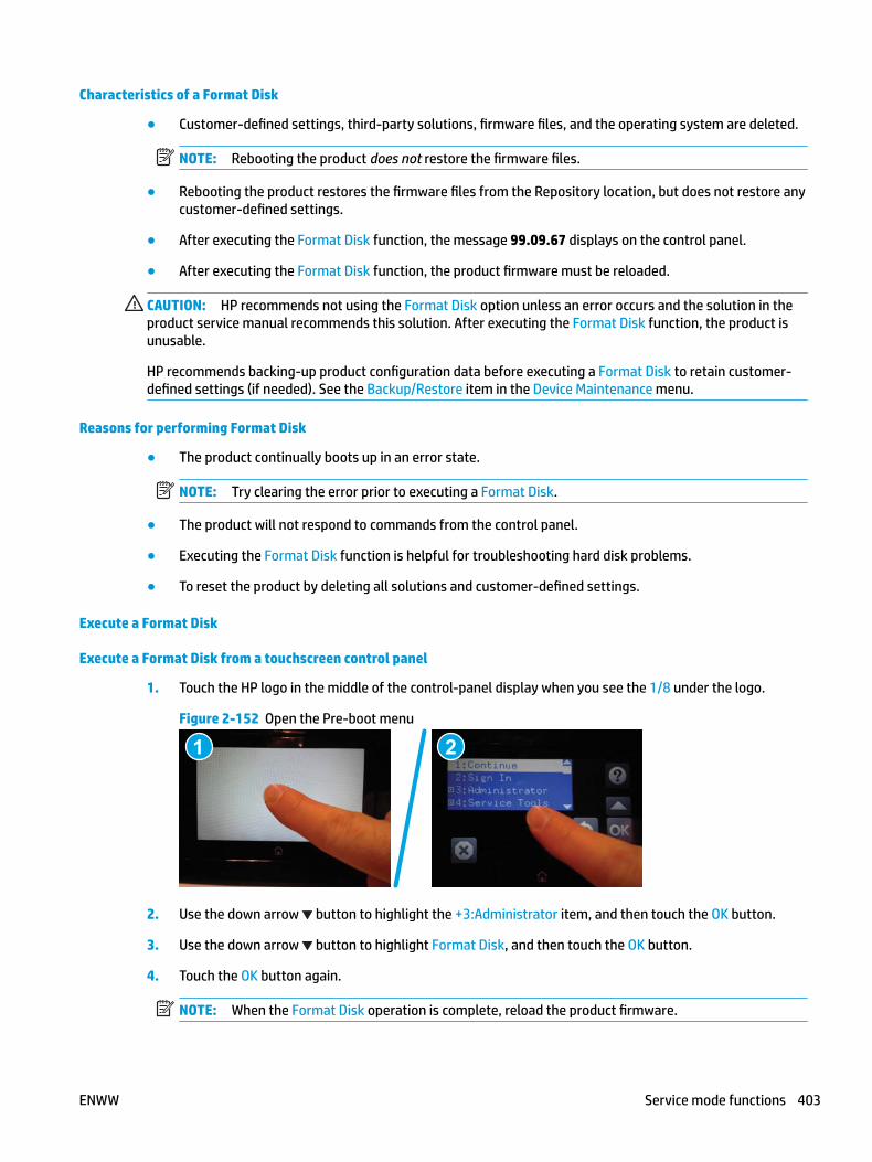
Characteristics of a Format Disk
● Customer-defined settings, third-party solutions, firmware files, and the operating system are deleted.
NOTE: Rebooting the product does not restore the firmware files.
● Rebooting the product restores the firmware files from the Repository location, but does not restore any customer-defined settings.
● After executing the Format Disk function, the message 99.09.67 displays on the control panel.
● After executing the Format Disk function, the product firmware must be reloaded.
CAUTION: HP recommends not using the Format Disk option unless an error occurs and the solution in the product service manual recommends this solution. After executing the Format Disk function, the product is unusable.
HP recommends backing-up product configuration data before executing a Format Disk to retain customer-defined settings (if needed). See the Backup/Restore item in the Device Maintenance menu.
Reasons for performing Format Disk
● The product continually boots up in an error state.
NOTE: Try clearing the error prior to executing a Format Disk.
● The product will not respond to commands from the control panel.
● Executing the Format Disk function is helpful for troubleshooting hard disk problems.
● To reset the product by deleting all solutions and customer-defined settings.
Execute a Format Disk
Execute a Format Disk from a touchscreen control panel
1. Touch the HP logo in the middle of the control-panel display when you see the 1/8 under the logo.
Figure 2-152 Open the Pre-boot menu
1 2
2. Use the down arrow button to highlight the +3:Administrator item, and then touch the OK button.
3. Use the down arrow button to highlight Format Disk, and then touch the OK button.
4. Touch the OK button again.
NOTE: When the Format Disk operation is complete, reload the product firmware.
ENWW Service mode functions 403

Execute a Format Disk from a LCD control panel
CAUTION: This procedure resets all product configurations and settings to factory defaults (customer configurations and settings are lost).
1. Press the Cancel button when you see the 1/8 under the logo.
2. Use the down arrow button to highlight the +3:Administrator item, and then press the OK button.
3. Use the down arrow button to highlight Format Disk, and then press the OK button.
4. Press the OK button again.
NOTE: When the Format Disk operation is complete, reload the product firmware.
404 Chapter 2 Solve problems ENWW
Firmware upgradesTo download the most recent firmware upgrade for the product, go to:
● In the US, go to www.hp.com/support/ljM604, www.hp.com/support/ljM605, www.hp.com/support/ljM606.
a. Select Get drivers, Software, and Firmware, and then select the appropriate product by name.
NOTE: More than one product model might be listed. Make sure to select the correct model so that the upgraded firmware supports all of the product functions.
b. Select the driver language and operating system.
c. Locate the firmware download, and then select Download.
● Outside the U.S., go to www.hp.com/support.
a. Select your country/region.
b. Select Drivers & Downloads.
c. Enter the product name in the Find my product dialogue box, and then select Go.
TIP: Click on the How do I find my product name/number? link to see a short video on identifying the printer name and number.
d. Select the appropriate product by name.
NOTE: More than one product model might be listed. Make sure to select the correct model so that the upgraded firmware supports all of the product functions.
e. Select the driver language and operating system.
f. Locate the firmware download, and then select Download.
● Determine the installed revision of firmware
● Perform a firmware upgrade
ENWW Firmware upgrades 405
Determine the installed revision of firmware
NOTE: Print a configuration page to determine the installed revision of firmware.
Print the configuration page from a touchsreen control panel
1. From the Home screen on the product control panel, scroll to and touch the Administration button.
2. Open the following menus:
● Reports
● Configuration/Status Pages
3. Touch Configuration Page to select it.
4. Touch the Print button to print the pages.
Print the configuration page from a LCD control panel
1. From the Home screen on the product control panel, use the down arrow button to scroll to Administration, and then press the OK button.
2. Open the following menus:
● Reports
● Configuration/Status Pages
3. Use the down arrow button to scroll to Configuration Page, and then press the OK button to select it.
4. Use the up arrow button to scroll to Print, and then press the OK button to print the pages.
406 Chapter 2 Solve problems ENWW
Perform a firmware upgradeThe firmware bundle is a .bdl file. This file requires an interactive upgrade method. The traditional FTP, LPR or Port 9100 methods of upgrading are not available. Use one of the following methods to upgrade the firmware for this product.
HP Embedded Web Server
NOTE: The product should be at the Ready state.
The firmware update might take 10 minutes or longer based on the input/output (I/O) transfer rates and the time it takes for the product to reinitialize.
1. Open an Internet browser window.
2. Enter the product IP address in the URL line.
3. Select the Firmware Upgrade link from the General tab or from the Troubleshooting tab.
4. Browse to the location that the firmware upgrade file was downloaded to, and then select the firmware file—the file has a .bdl file extension. Select the Install button to perform the upgrade.
NOTE: Do not close the browser window OR interrupt communication until the HP Embedded Web Server (EWS) displays the confirmation page.
5. Select Restart Now from the EWS confirmation page, or turn the product off, and then on again using the power switch.
6. After the product reinitializes, print a configuration page and verify that the latest firmware version has been installed.
ENWW Firmware upgrades 407
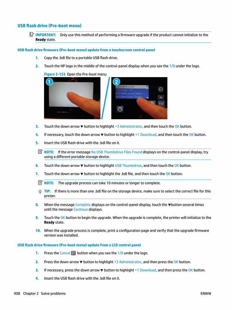
USB flash drive (Pre-boot menu)
IMPORTANT: Only use this method of performing a firmware upgrade if the product cannot initialize to the Ready state.
USB flash drive firmware (Pre-boot menu) update from a touchscreen control panel
1. Copy the .bdl file to a portable USB flash drive.
2. Touch the HP logo in the middle of the control-panel display when you see the 1/8 under the logo.
Figure 2-153 Open the Pre-boot menu
1 2
3. Touch the down arrow button to highlight +3 Administrator, and then touch the OK button.
4. If necessary, touch the down arrow button to highlight +1 Download, and then touch the OK button.
5. Insert the USB flash drive with the .bdl file on it.
NOTE: If the error message No USB Thumbdrive Files Found displays on the control-panel display, try using a different portable storage device.
6. Touch the down arrow button to highlight USB Thumbdrive, and then touch the OK button.
7. Touch the down arrow button to highlight the .bdl file, and then touch the OK button.
NOTE: The upgrade process can take 10 minutes or longer to complete.
TIP: If there is more than one .bdl file on the storage device, make sure to select the correct file for this printer.
8. When the message Complete displays on the control-panel display, touch the button several times until the message Continue displays.
9. Touch the OK button to begin the upgrade. When the upgrade is complete, the printer will initialize to the Ready state.
10. When the upgrade process is complete, print a configuration page and verify that the upgrade firmware version was installed.
USB flash drive firmware (Pre-boot menu) update from a LCD control panel
1. Press the Cancel button when you see the 1/8 under the logo.
2. Press the down arrow button to highlight +3 Administrator, and then press the OK button.
3. If necessary, press the down arrow button to highlight +1 Download, and then press the OK button.
4. Insert the USB flash drive with the .bdl file on it.
408 Chapter 2 Solve problems ENWW

NOTE: If the error message No USB Thumbdrive Files Found displays on the control-panel display, try using a different portable storage device.
5. Press the down arrow button to highlight USB Thumbdrive, and then press the OK button.
6. Press the down arrow button to highlight the .bdl file, and then press the OK button.
NOTE: The upgrade process can take 10 minutes or longer to complete.
TIP: If there is more than one .bdl file on the storage device, make sure to select the correct file for this product.
7. When the message Complete displays on the control-panel display, turn the product power off, and then on agian.
8. When the upgrade process is complete, print a configuration page and verify that the upgrade firmware version was installed.
ENWW Firmware upgrades 409

USB flash drive (control-panel menu)
NOTE: USB flash drives that are not using a FAT32 format, or do not have a CD formatted partition, might not be recognized by the product. If the product does not recognize a USB flash drive, try using a different USB flash drive.
TIP: The USB port on the product must be enabled. If it is disabled, use the Enable Retrieve from USB item in the General Settings menu to enable it.
USB flash drive firmware (control-panel menu) update from a touchscreen control panel
1. Copy the .bdl file to a portable USB flash drive.
2. Turn the product on, and then wait until it reaches the Ready state.
3. From the Home screen on the product control panel, scroll to and touch the Device Maintenance button.
4. Touch the USB Firmware Upgrade button.
5. Insert the portable USB storage device with the .bdl file on it into the USB port on the front of the product.
6. Touch the .bdl file, and then touch the Upgrade button.
TIP: If there is more than one .bdl file on the storage device, make sure to select the correct file for this product.
7. Select one of the following options:
● Upgrade
NOTE: The upgrade process can take 10 minutes or longer to complete.
● Re-install
● Downgrade
8. When the upgrade is complete, the product will initialize to the Ready state. Print a configuration page and verify that the upgrade firmware version was installed.
USB flash drive firmware (control-panel menu) update from a LCD control panel
1. From the Home screen on the product control panel, use the down arrow button to scroll to Device Maintenance, and then press the OK button.
2. Open the following menus:
● USB Firmware Upgrade
3. Insert the portable USB storage device with the .bdl file on it into the USB port on the product.
4. If necessary, use the down arrow button to scroll to the appropriate .bdl file, and then press the OK button to select.
5. Use the down arrow button to scroll to Upgrade, and then press the OK button to start the firmware upgrade.
NOTE: If the firmware in the .bdl file on the portable USB storage device matches the installed firmware on the product, Upgrade is replaced by Re-Install.
410 Chapter 2 Solve problems ENWW
A Printer specifications
● Printer dimensions
● Printer space requirements
● Power consumption, electrical specifications, and acoustic emissions
● Operating-environment range
● Certificate of Volatility
ENWW 411
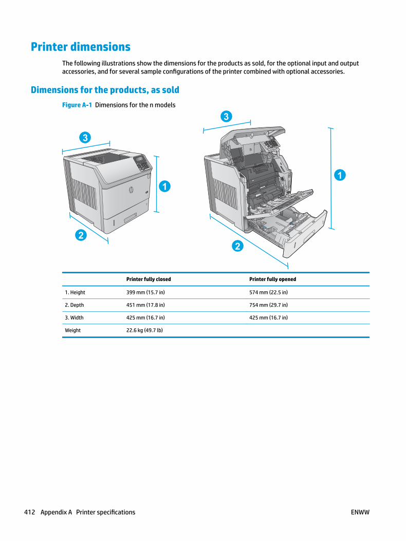
Printer dimensionsThe following illustrations show the dimensions for the products as sold, for the optional input and output accessories, and for several sample configurations of the printer combined with optional accessories.
Dimensions for the products, as soldFigure A-1 Dimensions for the n models
1
2
3
1
2
3
Printer fully closed Printer fully opened
1. Height 399 mm (15.7 in) 574 mm (22.5 in)
2. Depth 451 mm (17.8 in) 754 mm (29.7 in)
3. Width 425 mm (16.7 in) 425 mm (16.7 in)
Weight 22.6 kg (49.7 lb)
412 Appendix A Printer specifications ENWW
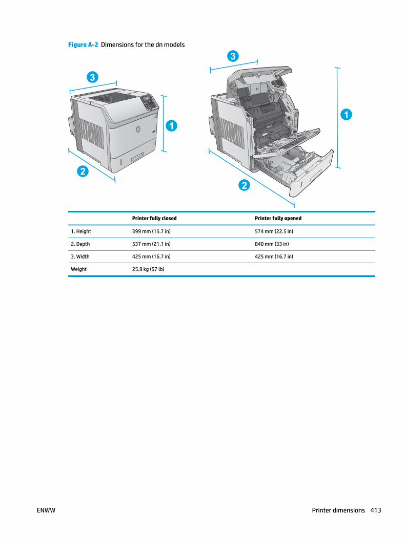
Figure A-2 Dimensions for the dn models
1
2
3
1
2
3
Printer fully closed Printer fully opened
1. Height 399 mm (15.7 in) 574 mm (22.5 in)
2. Depth 537 mm (21.1 in) 840 mm (33 in)
3. Width 425 mm (16.7 in) 425 mm (16.7 in)
Weight 25.9 kg (57 lb)
ENWW Printer dimensions 413

Figure A-3 Dimensions for the x models
3
3
3
1
2
3
1
2
3
Printer fully closed Printer fully opened
1. Height 521 mm (20.5 in) 695 mm (27.4 in)
2. Depth 537 mm (21.1 in) 840 mm (33 in)
3. Width 425 mm (16.7 in) 425 mm (16.7 in)
Weight 32.5 kg (71.5 lb)
Dimensions for the input and output accessoriesFigure A-4 Dimensions for the 1 x 500-sheet paper feeder
3
3 1
2
3
1. Height 121 mm (4.8 in)
414 Appendix A Printer specifications ENWW

2. Depth Tray closed: 448 mm (17.7 in)
Tray opened: 864 mm (34 in)
3. Width 415 mm (16.3 in)
Weight 6.7 kg (14.7 lb)
Figure A-5 Dimensions for the 1,500-sheet high-capacity input tray
1
2
3
1. Height 264 mm (10.4 in)
2. Depth Door closed: 448 mm (17.7 in)
Door opened: 902 mm (35.5 in)
3. Width 415 mm (16.3 in)
Weight 13 kg (14.7 lb)
ENWW Printer dimensions 415
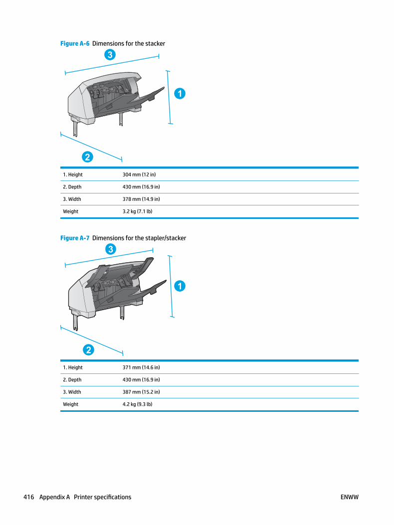
Figure A-6 Dimensions for the stacker
1
2
3
1. Height 304 mm (12 in)
2. Depth 430 mm (16.9 in)
3. Width 378 mm (14.9 in)
Weight 3.2 kg (7.1 lb)
Figure A-7 Dimensions for the stapler/stacker
1
2
3
1. Height 371 mm (14.6 in)
2. Depth 430 mm (16.9 in)
3. Width 387 mm (15.2 in)
Weight 4.2 kg (9.3 lb)
416 Appendix A Printer specifications ENWW
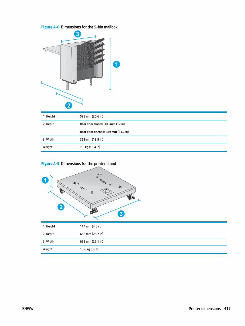
Figure A-8 Dimensions for the 5-bin mailbox
1
2
3
1. Height 522 mm (20.6 in)
2. Depth Rear door closed: 306 mm (12 in)
Rear door opened: 589 mm (23.2 in)
3. Width 353 mm (13.9 in)
Weight 7.0 kg (15.4 lb)
Figure A-9 Dimensions for the printer stand
1
23
1. Height 114 mm (4.5 in)
2. Depth 653 mm (25.7 in)
3. Width 663 mm (26.1 in)
Weight 13.6 kg (30 lb)
ENWW Printer dimensions 417
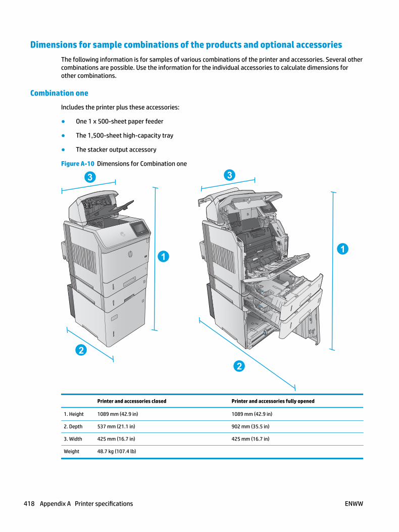
Dimensions for sample combinations of the products and optional accessoriesThe following information is for samples of various combinations of the printer and accessories. Several other combinations are possible. Use the information for the individual accessories to calculate dimensions for other combinations.
Combination one
Includes the printer plus these accessories:
● One 1 x 500-sheet paper feeder
● The 1,500-sheet high-capacity tray
● The stacker output accessory
Figure A-10 Dimensions for Combination one
3
3
3
3
1
2
1
2
33
Printer and accessories closed Printer and accessories fully opened
1. Height 1089 mm (42.9 in) 1089 mm (42.9 in)
2. Depth 537 mm (21.1 in) 902 mm (35.5 in)
3. Width 425 mm (16.7 in) 425 mm (16.7 in)
Weight 48.7 kg (107.4 lb)
418 Appendix A Printer specifications ENWW
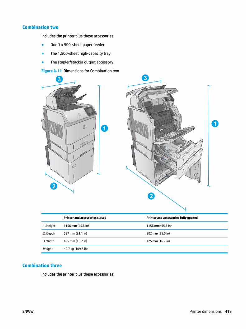
Combination two
Includes the printer plus these accessories:
● One 1 x 500-sheet paper feeder
● The 1,500-sheet high-capacity tray
● The stapler/stacker output accessory
Figure A-11 Dimensions for Combination two
3
3
3
3
1
2
1
2
33
Printer and accessories closed Printer and accessories fully opened
1. Height 1156 mm (45.5 in) 1156 mm (45.5 in)
2. Depth 537 mm (21.1 in) 902 mm (35.5 in)
3. Width 425 mm (16.7 in) 425 mm (16.7 in)
Weight 49.7 kg (109.6 lb)
Combination three
Includes the printer plus these accessories:
ENWW Printer dimensions 419
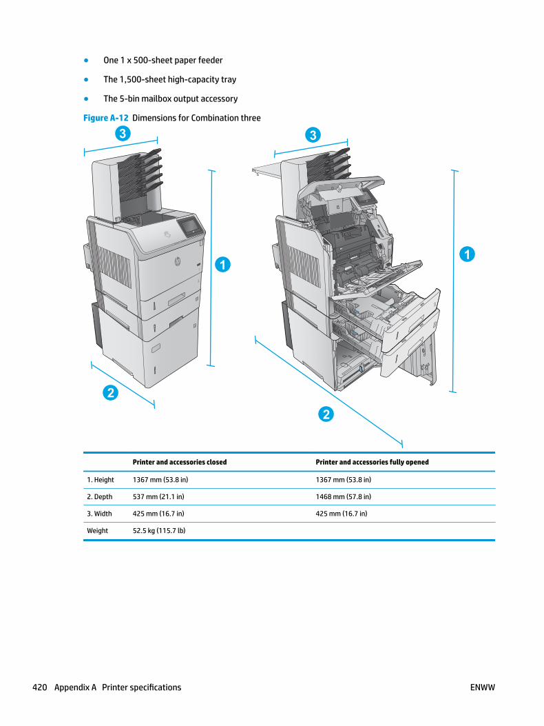
● One 1 x 500-sheet paper feeder
● The 1,500-sheet high-capacity tray
● The 5-bin mailbox output accessory
Figure A-12 Dimensions for Combination three
3
3
3
3
1
2
1
2
33
Printer and accessories closed Printer and accessories fully opened
1. Height 1367 mm (53.8 in) 1367 mm (53.8 in)
2. Depth 537 mm (21.1 in) 1468 mm (57.8 in)
3. Width 425 mm (16.7 in) 425 mm (16.7 in)
Weight 52.5 kg (115.7 lb)
420 Appendix A Printer specifications ENWW

Printer space requirementsHP recommends that 30 mm (1.81 in) be added to the printer dimensions provided in this chapter to make sure there is sufficient space to open doors and covers, and to provide proper ventilation. See Printer dimensions on page 412.
ENWW Printer space requirements 421

Power consumption, electrical specifications, and acoustic emissions
See www.hp.com/support/ljM604, www.hp.com/support/ljM605, www.hp.com/support/ljM606 for current information.
CAUTION: Power requirements are based on the country/region where the printer is sold. Do not convert operating voltages. This will damage the printer and void the printer warranty.
422 Appendix A Printer specifications ENWW

Operating-environment rangeTable A-1 Operating-environment specifications
Environment Recommended Allowed
Temperature 7.5° to 32.5°C (45.5° to 90.5°F) 0° to 35°C (32° to 95°F)
Relative humidity 5% to 90% relative humidity (RH) 35% to 85% RH
Altitude Not applicable 0 to 3048 m (0 to 10,000 ft)
ENWW Operating-environment range 423
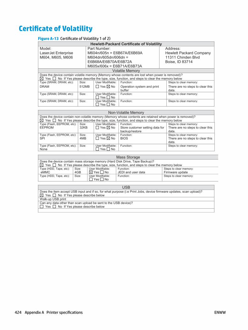
Certificate of VolatilityFigure A-13 Certificate of Volatility 1 of 2)
Hewlett-Packard Certificate of Volatility Model: Part Number: Address: LaserJet Enterprise M604, M605, M606
M604n/605n = E6B67A/E6B69A M604dn/605dn/606dn = E6B68A/E6B70A/E6B72A M605x/606x = E6B71A/E6B73A
Hewlett Packard Company 11311 Chinden Blvd Boise, ID 83714
Volatile Memory Does the device contain volatile memory (Memory whose contents are lost when power is removed)?
Yes No If Yes please describe the type, size, function, and steps to clear the memory below Type (SRAM, DRAM, etc): Size: User Modifiable: Function: Steps to clear memory: DRAM 512MB Yes No Operation system and print
buffer There are no steps to clear this data.
Type (SRAM, DRAM, etc): Size: User Modifiable: Function: Steps to clear memory: Yes No Type (SRAM, DRAM, etc): Size: User Modifiable: Function: Steps to clear memory: Yes No
Non-Volatile Memory Does the device contain non-volatile memory (Memory whose contents are retained when power is removed)?
Yes No If Yes please describe the type, size, function, and steps to clear the memory below Type (Flash, EEPROM, etc): Size: User Modifiable: Function: Steps to clear memory: EEPROM 32KB Yes No Store customer setting data for
backup/restore There are no steps to clear this data.
Type (Flash, EEPROM, etc): Size: User Modifiable: Function: Steps to clear memory: SPI 4MB Yes No BIOS There are no steps to clear this
data. Type (Flash, EEPROM, etc): Size: User Modifiable: Function: Steps to clear memory: None Yes No
Mass Storage Does the device contain mass storage memory (Hard Disk Drive, Tape Backup)?
Yes No If Yes please describe the type, size, function, and steps to clear the memory below Type (HDD, Tape, etc): Size: User Modifiable: Function: Steps to clear memory: eMMC 4GB Yes No JEDI and user data Firmware update Type (HDD, Tape, etc): Size: User Modifiable: Function: Steps to clear memory: Yes No
USB Does the item accept USB input and if so, for what purpose (i.e Print Jobs, device firmware updates, scan upload)?
Yes No If Yes please describe below Walk-up USB print Can any data other than scan upload be sent to the USB device)?
Yes No If Yes please describe below
424 Appendix A Printer specifications ENWW

Figure A-14 Certificate of Volatility (2 of 2)RF/RFID
Does the item use RF or RFID for receive or transmit of any data including remote diagnostics. (e.g. Cellular phone, Bluetooth) Yes No If Yes please describe below Purpose Frequency:) Bandwidth: Modulation: Effective Radiate Power (ERP):
Specifications:
Other Transmission Capabilities Does the device employ any other methods of non-wired access to transmit or receive any data whatsoever (e.g. anything other than standard hard wired TCP/IP, direct USB, or parallel connections)? Yes No If Yes please describe below: Purpose: Wireless direct print. Frequency: 2.4Ghz Bandwidth: Modulation: Effective Radiate Power (ERP: Specifications: 802.11 b/g
Other Capabilities Does the device employ any other method of communications such as a Modem to transmit or receive any data whatsoever? Yes No If Yes please describe below: Purpose: NFC; to support tap to print only Specifications: NFC Tag Type 4 ISO 14443B
Author Information Name: Title: Email: Business Unit: Security Technical
Marketing Engineer IPG
Date Prepared: 01/15/15
ENWW Certificate of Volatility 425

426 Appendix A Printer specifications ENWW
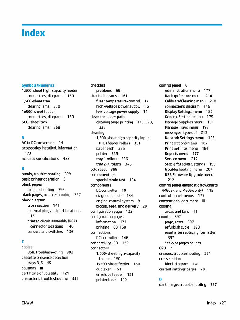
Index
Symbols/Numerics1,500-sheet high-capacity feeder
connectors, diagrams 1501,500-sheet tray
clearing jams 3701x500-sheet feeder
connectors, diagrams 150500–sheet tray
clearing jams 368
AAC to DC conversion 14accessories installed, information
173acoustic specifications 422
Bbands, troubleshooting 329basic printer operation 3blank pages
troubleshooting 392blank pages, troubleshooting 327block diagram
cross section 141external plug and port locations
151printed circuit assembly (PCA)
connector locations 146sensors and switches 136
Ccables
USB, troubleshooting 392cassette presence detection
trays 3-6 45cautions iiicertificate of volatility 424characters, troubleshooting 331
checklistproblems 65
circuit diagrams 161fuser temperature-control 17high-voltage power supply 16low-voltage power supply 14
clean the paper pathcleaning page printing 176, 323,
335cleaning
1,500-sheet high capacity input (HCI) feeder rollers 351
paper path 335printer 335tray 1 rollers 336tray 2-X rollers 345
cold reset 398component test
special mode test 134components
DC controller 10diagnostic tests 134engine-control system 9pickup, feed, and delivery 28
configuration page 122configuration pages
information 173printing 68, 168
connectionsDC controller 146
connectivity LED 122connectors
1,500-sheet high-capacity feeder 150
1x500-sheet feeder 150duplexer 151envelope feeder 151printer base 149
control panel 6Administration menu 177Backup/Restore menu 210Calibrate/Cleaning menu 210connections diagram 146Display Settings menu 189General Settings menu 179Manage Supplies menu 191Manage Trays menu 193messages, types of 213Network Settings menu 196Print Options menu 187Print Settings menu 184Reports menu 177Service menu 212Stapler/Stacker Settings 195troubleshooting menu 207USB Firmware Upgrade menu
212control panel diagnostic flowcharts
(M605x and M606x only) 115control-panel menus 177conventions, document iiicooling
areas and fans 11counts 397
page, reset 397refurbish cycle 398reset after replacing formatter
397See also pages counts
CPU 7creases, troubleshooting 331cross section
block diagram 141current settings pages 70
Ddark image, troubleshooting 327
ENWW Index 427

datecodes for firmware 173product first used 398
DC controllercomponents 10connections, diagrams 146fans 11motors 11sensors 13solenoids 12switches 12
DC motors 11DC voltages converted from AC 14defeating
interlocks 124demo page 122determine problem source 91determine the installed revision of firmware 406
development process 24diagnostics
component 134engine 123LED 122networks 201
diagramsblock 136circuit 161DC controller connections 146formatter connectors 148main assemblies (printer base)
153motors and fans (printer base)
155printed circuit assemblies (PCAs;
printer base) 156timing 160
dimensions, printer 412document conventions iiidriver PCA
envelope feeder 52, 57drum charge elimination 27drum cleaning 26duplex printing accessory
connections diagram 146duplexer
clearing jams 382connectors, diagrams 151electrical components 58jam detection 62
motor control 57paper pickup 59theroy of operation 57
duplexing unitmotors 11
Eelectrical components
duplexer 58envelope feeder 53HCI 48trays 3-6 43
electrical specifications 422embedded web server 407engine
diagnostics 123test page 123
engine power supplyconnections diagram 146
engine-control systemcomponents 9
envelope feederclearing jams 384connections diagram 146connectors, diagrams 151driver PCA 52, 57electrical components 53jam detection 56motor control 52multiple feed detection 54multiple feed prevention 54paper pickup 54theroy of operation 52
error messagestypes of 213
event log 70, 122clear 313, 398clear using LCD control panel 72clear using touchscreen control
panel 71information 173print 312view 312
event-log messages 311exhaust fans 11external plug and port locations
block diagram 151
Ffaded print 327
failure detectionlow-voltage power supply 15motors 11
fansconnections diagram 146DC controller 11exhaust 11intake 11
firmwaredate codes 173
firmware, downloading new 405flowcharts
troubleshooting 91formatter
connections diagram 146resets after replacing 397
formatter connectorsdiagrams 148
formatter control system 5formatter lights 122fuser 17
clearing jams 376connections diagram 146control-circuit function 17identification 18life detection 18temperature control 17See also fusing and delivery unit
fuser test pageprint 174, 175
fusing process 26
Hhardware integration pocket (HIP) is
not functioning 121HCI
driver PCA 46electrical components 48jam detection 51media size detection 48motor control 47multiple feed prevention 49paper pickup 48theroy of operation 46tray lift operation 50
HCI driver PCApaper deck 46
HCI trayclearing jams 370lift operation 50
428 Index ENWW
HCI, 1,500-sheet high capacity input feeder rollers
cleaning 351heat control for fuser 17high-voltage power supply (HVPS)
operations 16home button is unresponsive 120horizontal lines, troubleshooting
329HP embedded Jetdirect page 170,
171HP Jetdirect print server
configuration page 170lights 122
HVPS (high-voltage power supply)operations 16
II/O interfaces 7image information process 22image quality
1,500-sheet high capacity input (HCI) feeder rollers, clean 351
check paper and the printing environment 324
check toner-cartridge status322
clean the printer 323inspect the toner cartridge 324tray 1 rollers, clean 336tray 2-X rollers, clean 345
image quality issuesexamples and solutions 327
image-formation processdevelopment process 24drum charge elimination 27drum cleaning 26fusing process 26laser-beam exposure 24primary charging 23primary transfer process 25separation process 25
imaging drumsdiagnostic test 125
individual component diagnostics122
initial rotation period 4input/output interfaces 7
installationdate calculation 398verify for optional accessories
68, 168intake fans 11interlocks
defeating 124interpret control-panel messages and
event log entries 213IPv4 information 170, 172IPv6 information 170, 172
Jjam detection sensors (printer base)
location 35jams 370
1,500-sheet tray 370500–sheet trays 368auto-navigation 365causes of 365detection in duplexer 62detection in envelope feeder 56detection in HCI 51detection in trays 3-6 45diagnostic test for 126duplexer 382envelope feeder 384fuser 376HCI tray 370mailbox accessory 386output bin 381rear output bin 375recovery 391sensor locations 362sensors and switches 1x500-
sheet feeder 363sensors HCI 364, 365sensors, product base 362stacking accessory 388stapling accessory 388toner cartridge area 372Tray 1 367Tray 2 368
Jetdirect print serverlights 122
Kkeyboard 6
Llaser-beam exposure 24
laser/scanneroperations 19
laser/scanner assemblyconnections diagram 146
last rotation period 4latent image formation 23LEDs. See lightslight print, troubleshooting 327lights
formatter 122troubleshooting with 122
lines, troubleshooting 329link speed settings 205loose toner, troubleshooting 331low-voltage power supply (LVPS)
converted DC voltages 14failure detection 15operations 14protection for components 15stops and interruptions 14
LVPS (low-voltage power supply)converted DC voltages 14failure detection 15operations 14protection for components 15stops and interruptions 14
Mmailbox accessory
clearing jams 386main assemblies (printer base)
block diagram 153manual print modes 324media size detection
trays 3-6 44Memory Enhancement technology
(MEt) 8menu map 69messages
types of 213motor control
duplexer feeder 57envelope feeder 52HCI 47trays 3-6 43
motorsconnections diagram 146DC controller 11failure detection 11stepping 11
ENWW Index 429

motors and fans (printer base)block diagram 155
movement of paper through product. See pickup, feed, and delivery
multiple feed detectionenvelope feeder 54
multiple feed preventionenvelope feeder 54trays 3-6 45
Nnetworks
diagnostics 201HP embedded Jetdirect configuration page 170
link speed settings 205wireless page 171
no control panel sound 119notes iii
Ooperation
Sleep mode 5operation sequence 4operations
laser/scanner 19output bin
clearing jams 381over-current protection 15over-voltage protection 15
Ppages
blank 392not printing 392printing slowly 392
pages count 397reset 397See also counts
paperdefault size reset 398jam detection, duplexer 62jam detection, envelope feeder
56jam detection, HCI 51jams 365stop in path for testing 133trays 3-6 jam detection 45wrinkled 331
paper feedertrays 3-6 driver PCA 42
paper handlingsolve problems 357
paper movementoperation 28
paper pathdiagnostic test 126product 28stop movement for testing 133
paper pickupduplexer 59envelope feeder 54HCI 48trays 3-6 44
paper-pathtest, sensors 127
passwordService menu PIN 397
periods of the operation sequence4
pickup, feed, and deliverycomponents 28overview 28
PJL (printer job language) 6PML (printer management
language) 6power
consumption 422power subsystem 92power supply 14
connections diagram 146troubleshooting 92See also low-voltage power
supply; high-voltage power supply
power-on troubleshooting overview 92
power-save mode. See sleep settingspre-boot menu options 73primary charging process 23print quality
built-in troubleshooting pages318
check the paper-type setting for the print job 322
manual print modes 324test pages 168use a different software
program 322Print Test Page 180print-quality troubleshooting 314
print-quality, solve 314printed circuit asembly (PCA)
connector locationsblock diagram 146
printed circuit assemblies (PCAs; printer base)
block diagram 156printer job language (PJL) 6printer management language
(PML) 6printer space requirements 421printing
modes, manual 324period in operation sequence 4stop for testing 133troubleshooting 392
problem-solvingevent-log messages 311messages, types of 213networks 201
product baseconnectors, diagrams 149
product cold reset 400product resets 398
Rrear output bin
clearing jams 375restore factory settings 398restore the service ID 399
Ssecurity settings information 170,
171sensors
block diagram 136connections diagram 146DC controller 13diagnostic tests 127pickup, feed, and delivery
system 28tests, diagnostic sensor and paper
path 126tests, manual tray/bin 131
separation process 25serial number 398service and support information v,
2, 64
430 Index ENWW
Service IDconvert to date 398restore 398
Service menu options 397service mode functions 397settings
restore factory 398Sleep mode
operation 5sleep settings 5
voltage too high during 15solenoids
DC controller 12solve connectivity problems 395solve performance problems 392
factors affecting print performance 392
print speeds 393product does not print or it prints
slowly 393product prints slowly 394
solve problems 63output is curled or wrinkled 358paper does not feed
automatically 360paper does not feed from Tray 2-
X 358paper handling 357product does not pick up paper
359product does not pick up paper or
misfeeds 359product feeds incorrect page
size 357product picks up multiple sheets
of paper 360product pulls from incorrect
tray 357product will not duplex or
duplexes incorrectly 357solving
direct-connect problems 395space requirements, printer 421specifications
electrical and acoustic 422space requirements 421
stacking accessoryclearing jams 388
standby period 4
staples in the stapling accessoryclearing jams 388
stapling accessoryclearing jams 388
statusmessages, types of 213
status page 122stepping motors 11stop printing for test 133streaks, troubleshooting 329sub-voltage
low-voltage power supply circuit 14
switchesblock diagram 136connections diagram 146DC controller 12
TTCP/IP information 170, 171temperature
control for fuser 17test pages
fuser 174, 175tests
component tests list and descriptions 135
disable cartridge check 125engine 123networks 201paper path 126paper path and sensor
diagnostic 126paper-path sensors 127print/stop 133tray/bin manual sensor 131
text, troubleshooting 331theory of operation
duplexer 57trays 3-6 42
theroy of operationenvelope feeder 52HCI 46
timing chart 160tips iiitoner
image formation, use during 23loose, troubleshooting 331
toner cartridge areaclearing jams 372
toner cartridgesdiagnostic test 125
touchscreen blank, white, or dim (no image) 116
touchscreen control panel 6touchscreen has an unresponsive
zone 118touchscreen is slow to respond 117transfer processes 25tray
HCI multiple feed prevention 49Tray 1
clearing jams 367tray 1 rollers
cleaning 336Tray 2
clearing jams 368tray 2-X rollers
cleaning 345tray lift operation
trays 3-6 45tray selection - use requested tray
193trays 3-6
electrical components 43jam detection 45media size detection 44multiple feed prevention 45paper pickup 44theory of operation 42tray lift operation 45tray presence detection 45tray X motor control 43
trays 3-6 driver PCApaper feeder 42
troubleshooting 63blank pages 392check paper and the printing
environment 324check the paper-type setting for
the print job 322check toner-cartridge status
322checklist 65clean the paper path 176, 323,
335clean the printer 323configuration page 122configuration pages for 68, 168control panel checks 95
ENWW Index 431

demo page 122direct-connect problems 395event log 122flowchart 91inspect the toner cartridge 324jams 362, 365lights, using 122lines, printed pages 329network problems 395pages not printing 392pages printing slowly 392power 92print from a different software
program 322print quality 318process 91reports and tools 122status page 122text 331USB cables 392wired network 395wrinkles 331
Uunderstand lights on the formatter
formatter lights 122understand the lights on the
formatterheartbeat LED 122HP Jetdirect LEDs 123
upgrade firmware 407upgrades, downloading product firmware 405
USB flash drivefirmware upgrade, control
panel 410firmware upgrade, pre-boot
menu 408USB port
troubleshooting 392Use Requested Tray 193
Vvertical lines, troubleshooting 329
Wwaiting period 4warnings iiiwarranty date information 398weight, printer 412white spots, troubleshooting 328
wirelessconfiguration page 171
wrinkles, troubleshooting 331
432 Index ENWW


© 2015 Hewlett-Packard Development Company, L.P.
www.hp.com