lateral stability considerations of timber beams in old...
TRANSCRIPT

18 Transportation Research Record 1053
Lateral Stability Considerations of
Timber Beams in Old Bridges
BRUCE A. SUPRENANT, FRED VIDEON, RICHARD EHLERT, and ALAN JACKSON
ABSTRACT
Some timber bridges built in the early 1900s do not have the roadway deck attached to the beams. These laterally unsupported beams are not capable of supporting current truck loads. County and state engineers who have inherited the responsibilities of maintaining these bridges must use considerable skill in developing a lateral bracing scheme for the beams. County engineers are usually working within a definite financial constraint such as the county budget. This paper was written to help engineers understand the history, theory, and practical solutions required for bracing timber beams in old bridges. A history of the early requirements for the design and construction of bridges is reported. The 5-ton loading requirement of the early 1900s does not compare with the current truck loads of 15 tons or higher. A brief discussion of the theory of lateral buckling of beams is presented along with methods to calculate the forces in the bracing. The c,iirrent AASHTO design practice for laterally unsupported beams is presented. The effect on the allowable stresses resulting from lateral bracing of beams is shown. Some deck-to-beam and beam-to-beam connections are presented as possible solutions to the beam instability problem. The deck-to-beam connections discussed are nailing, bolting, reverse bolting, angles and bolts, and friction. The beam-to-beam connections presented are blocking, cross-bridging, and tension side bracing. The advantages and disadvantages of each type of connection is discussed. Tension side bracing of beams, while perhaps being economically feasible, has not been verified either analytically or experimentally. There are no current design guidelines for tension side bracing.
The ingenuity and skill of an engineer can be tested when developing a rehabilitation scheme for an existing bridge. In addition, if that bridge was built between 1900 and 1920, the engineers' problem is even further complicated. County and state highway engineers have inherited the responsibility of maintaining many old bridges. A common problem of timber bridges built in the early 1900s is the lack of later al supper t provided to the beams. In other words, the deck planks were not attached to the timber beams and no other lateral bracing was provided. These laterally unsupported beams may have been strong enough for the loading requirements of the early 1900s, but buckle laterally under current truck loads.
Television reporters always seem to find it highly amusing to show pictures of a school bus stopped at a bridge while the children walk across. Figure 1 shows su.ch a bridge located in Montana. The capacity of this bridge was limited by the moment capacity of the beams. The beams were laterally unsupported for the full length. To increase the moment capacity of the beams, county personnel worked for two weeks to add blocking between the beams. This blocking, which proved to be an expensive operation, is shown in Figure 2. However, after the beams were braced, the load capacity of the bridge was increased. Figure 3 shows the posted load limits for the rehabilitated bridge.
Typically, county engineers encounter a technical and financial problem in that most counties do not
B.A. Suprenant, F. Videen, R. Ehlert. Department of Civil Engineering, University of Wyoming, Laramie, Wyo. 82070. A. Jackson. Department of Civil Engineering, Montana State University, Bozeman, Mont. 59715.
FIGURE 1 Old County Bridge.
usually have sufficient funds to maintain all of the bridges in their jurisdiction. The topics specifically addressed herein, which concern laterally unsupported beams, are (a) their lack of strength, (b) their theory and practice, and (c) rehabilitation techniques for increasing the bridge capacity by decreasing their length. The material presented is not intended to be theoretical, but rather oriented for the practicing engineer.
HISTORY
In the early 1900s, some companies had prepared general specifications for the design and construction of bridges. It appears that the American Bridge Company set the standard for the era. This compan}'

Suprenant . et al.
FIGURE 2 New blocking placed between existing steel and timber beams.
FIGURE 3 Posted weight limits for rehabilitated bridge.
not only had general specifications for the design of bridges but had also published a book in 1901 entitled, Standards for Structural Details <!>· The specifications prepared by the American Bridge Company and J.A.L. Waddell, a consulting engineer, will be reviewed to illustrate the standard design of the early 1900s. A comparison of the design requirements of early timber bridges and current requirements will show the necessity for bracing timber bridge beams.
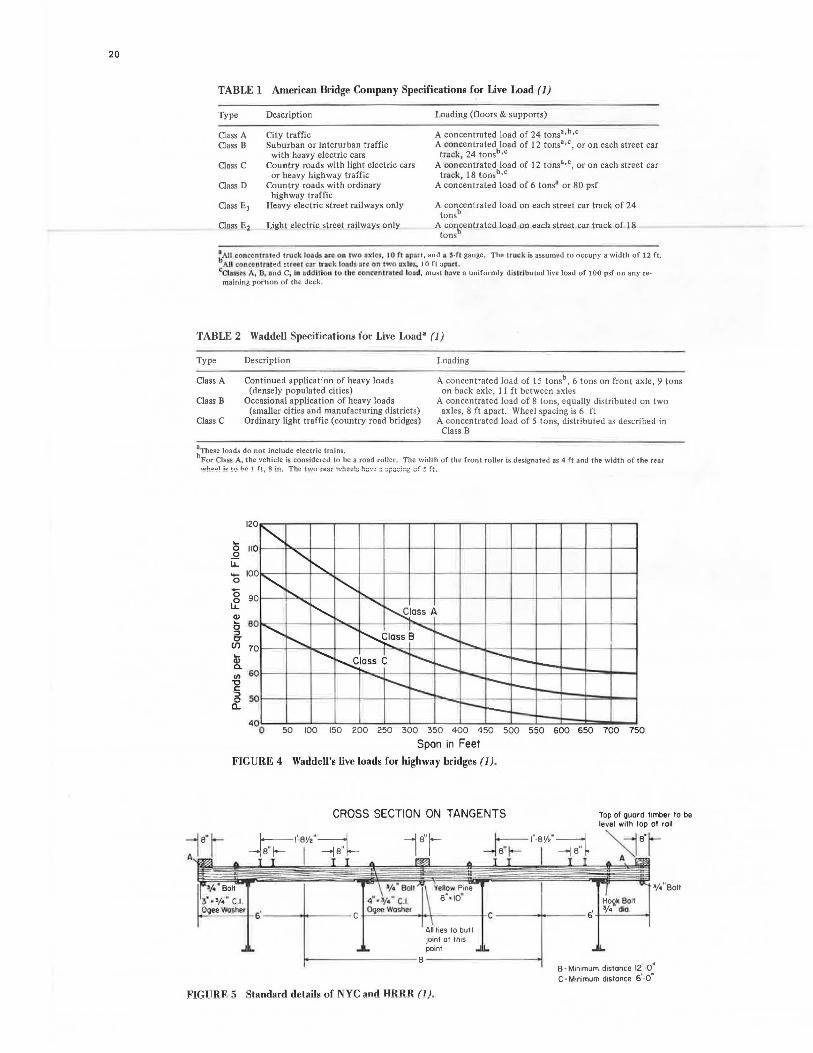
The Arner ican Bridge Company, in their specifications, divided highway bridges into six classes (1). These classes, with their descriptions and loading information, are given in Table 1.
J.A.L. Waddell divided highway bripges into three classes (~) • These classes, with their description and loading information, are given in Table 2. Waddell' s specifications (1) require that the designer assess the loading that is due to electric trains. Waddell also requires that a uniformly distributed live load be considered on the entire roadway, including footwalks. This uniformly distributed design load is determined from Figure 4, provided in the specifications. Waddell states,
"In addition to these (uniformly distributed) loads, the floor, joists, floor-beams, beam
hangers, and primary truss members are to be proportioned for the following concentrated loads (shown in Table 2), which are, however, supposed to occupy a whole panel length of the main roadway to the exclusion of the other live loads there (excepting only the electric-railway live load)" (!).
19
The specifications provide a good overview of the loading requirements of bridges. However, the design and construction requirements of the beams, specifically those concerning bracing and attachment of the deck, were difficult to assess.
The specifications of this era, 1900-1910, provided significant information regarding the stability of beams, through attachment to the deck, for railroad bridges. For instance, the American Bridge Company (ll required 8-in. x 8-in. deck timbers with a center-to-center spacing of 14 in. or less. The timbers were required to be notched 1/2 in. and have a full and even bearing over every beam. Every fifth deck tie was to be fastened to the beam by a 3/4-in. bolt. These typical requirements for railroad bridges assured the lateral stability of the beam by the attachment of the deck. Figure 5 shows the attachment of the deck to the beams for a railroad bridge. This is a typical floor system used by the New York Central and Hudson River Railroad Companies (NYC and HRRR).
The specifications are not as precise for bridges that would be categorized as Class D (American Bridge Company) or Class C (Waddell) • For instance, the American Bridge Company specifications (1) indicate the following for roadway planks a-;:;:d stringers:
1. For roadway planks, "For single thickness, the roadway planks shall not be less than 3 inches thick, nor less than one twelfth of the distance between stringers, and shall be laid transversely with 1/ 4 inch openings.
"When an additional wearing surface is specified for the roadway, it shall be 1 1/2 inches thick, and the lower planks, of a minimum thickness of 2 1/2 inches, shall be laid diagonally and with 1/2 inch openings."
2. For stringers, "Wooden joists shall not be less than 3 inches thick, shall be spaced not more than 2 1/2 feet between centers and shall be dapped over the seat angles or floor beams to exact level. In the latter case, they shall lap by each other over the full width of the floor beam, and shall be separated 1/2 inch for free circulation of air."
As is evident, the specifications do not mention any attachment of the roadway planks (deck) to the beams or bracing of the stringers (beams).
It has been the authors' experience that county engineers are encountering bridge structures which, in 1900, would have been classified as Class D (American Bridge Company) or Class C (Waddell). The bridge structures typically do not have braced beams, either through attachment to the deck or by extra bracing. The necessity for braced beams has been dictated by the increased loading requirements of new vehicles. A comparison will be made between existing design requirements and those for which the bridge was originally designed.
The American Association of State Highway and Transportation Officials (AASHTO) has indicated the loading requirements in the 1983 Standard Specifications for Highway Bridges (3). AASHTO provides four standard classes of highway loadings: H 20, H 15, HS 20, and HS 15. For comparison, H 15 (the smallest loading) will be considered as the design requirement for a rural county road.
20
TABLE 1 American Bridge Company Specifications for Live Load (1)
Type
Class A Class B
Class C
Class D
Description
City traffic Suburban or interurban traffic
with heavy electric cars Country roads with light electric cars
or heavy highway traffic Country roads with ordinary
highway traffic Heavy electric street railways only
Light electric street railways only
Loading (floors & supports)
A concentrated load of 24 tons• ,b,c A concentrated load of 12 tons••< , or on each street car
track 24 tonsb,c A con~entrated load of 12 tons•,<, or on each street car
track, 18 tonsb ,c A concentrated load of 6 tons' or 80 psf
A concentrated load on each street car track of 24 tonsb
A co'.\,°entrated load on each street car track of 18 tons
~AH conccn1nued truck lo L\ds arc on 1wo oxlc,, JO f1 op"rt, and 11 S·ft gauge. The truc k is assumed to o ccupy a width of 12 ft. All c.oncc ntrrued stree1 cnr trnck load$ i re on cwo uxlo:-.-, 10 ft apout.
eCl11$su A , 0, i:ind C, ln nddiHon 10 lhc conc:en tr-1.u:d lo ;s.J, must hnve a uniform1y disu lbuted live load of 100 psf o n any remaining portion of the deck.
TABLE 2 Waddell Specifications for Live Load' (1)
Type
Class A
Class B
Class C
Description
Continued application of heavy loads (densely populated cities)
Occasional application of heavy loads (smaller cities and manufacturing districts)
Ordinary light traffic (country road bridges)
Loading
A concentrated load of 15 tonsb, 6 tons on front axle, 9 tons on back axle, 11 ft between axles
A concentrated load of 8 tons, equally distributed on two axles, 8 ft apart. Wheel spacing is 6 ft
A concentrated load of 5 tons, distributed as described in Class B
~These loads do not include electric trains. For Class A, the vehicle is considered to be a road roller . The width of the front roller is designated as 4 ft and the width of the rear
120
..... 0 110 0
Li: - 100 0
0 ~ 90
Cl> 6 BO ::J CT en 10 ..... Cl> a. VI 60 -0 § ~
50
40
"""' ........ !'-..
"" :-..... '~ ............
............ ...........
"'~ ....... ~
~ass A
....... N.'. I ......., ~ ass B i-..._
I ~ .......... r-....... I"--Nlass C I'-.. --.......... ......._ ~r--r---- r--r-- .........
0 50 100 150 200 250 300 350 400 450 500 550 600 650 700 750
Span in Feet
FIGURE 4 Waddell's live loads for highway bridges (1) .
CROSS SECTION ON TANGENTS Top of guard limber to be level with top of roil
~l··r·~ ~a·r--•• ~ joinl at this point
io-~~~~~~~~~0~~~~~~~~~~-1
FIGURE 5 Standard details of NYC and HRRR (1) .
•/•"Bolt
B ·Minimum distance 12'·011
C-Minimum distance 61
·0"

Suprenant et al.
AASHTO Specifications <ll are, unfortunately, not as simple to interpret as the early specifications <!.l • The H 15 loading consists of a total truck weight of 15 tons. The distribution of the weight to the two axles spaced 14 ft apart is 3 tons to the front axle and 12 tons to the rear axle. The truck is assumed to occupy a lane width of 10 ft. The spacing of the wheels on an axle is assumed to be 6 ft. However, an equivalent lane loading is also provided for H 15 loading. The equivalent lane loading requires a uniform load of 480 lb per linear foot of loaded lane and, in addition, a single concentrated moving load of 13,500 lb for moment calculations and a single concentrated moving load of 19,500 lb for shear calculations.
To compare the current AASHTO H 15 loading with those required by early specifications, a typical 20-ft bridge structure is investigated._ Table 3 gives the maximum moment and shear calculated from the three different loadings given in the specifications. For the AASHTO loading, the truck load was
TABLE 3 Comparison of Maximum Moment and Shear
Loading
AASHTO- H 15 (l 5 tons, 14-ft axle spacing) American Bridge Company-Class D (6 tons,
I 0-ft axle spacing) Waddell- Class C (5 tons, 8-ft axle spacing)
Maximum Moment (ft-lb)
120,000
33,750 40,000
Maximum Shear (lb)
25,800
9,000 8,000
used rather than the equivalent lane loading. The data in Table 3 indicate the dilenuna faced by the county bridge engineer. The increase in moment requirements is approximately a factor of 3. Certainly one way to increase the load capacity of a long slender beam is to brace the beam. The desire is to prevent a stability failure (buckling) and ensure a material failure. The possibility of increasing the failure stress by a factor of 3 will be considered in the next section.
This example clearly shows the predicament an engineer encounters when trying to upgrade an old bridge to meet current truck loads. The engineers' ability to solve this problem may be further hampered by the designation of the bridge as a historic structurei thus, consitlerable ingenuity and skill would be required in restoring and strengthening (without changing the style and appearance of) the structure.
THEORY
The allowable moment capacity of a beam in bending is determined by multiplying its section modulus by the allowable stress. The allowable stress may be based on a material failure or a stability failure (buckling). An allowable stress based on a material failure will give the highest beam moment capacity. The allowable stress for buckling is always less than that for a material failure. Economy would seem to dictate a beam braced to prevent buckling, so that the highest beam moment capacity could be obtained.
It is well known that long rectangular beams with no laterial restraint may buckle. The lateral buckling of a beam is a function of the beam's torsional and flexural rigidity, loading, beam length, and bracing. Lateral buckling in timber beams may occur as a result of the compressive stress introduced in the top portion of the beam. This compressive stress
21
is due to flexural bending of the member. This bending compressive stress can be thought of as creating an equivalent column-buckling problem in the compressive half of the beam. If buckling occurs, the beam will deflect laterally between points of bracing or support. Figure 6 shows the buckled configuration of a narrow rectangular beam. In practice, most beams are braced to prevent lateral buckling, thereby ensuring a material failure.
y
y
FIGURE 6 Buckled configuration of long narrow rectangular beam (4).
In most cases, the question of lateral instability is eliminated by providing lateral support to the compression side of the beam at close intervals. If the deck members can ·be attached to the beams, lateral instability is prevented by continuous lateral support. If the deck cannot be attached, crossbridging at regular intervals will also prevent the beam from buckling laterally.
Although it would seem reasonable to attach the deck to the beams, this is not always possible. Also, placing cross-bridging on an existing bridge may not be feasible, either economically or technically. The discussion of preventing lateral buckling has indicated a requirement of bracing the compression flange of the beam. Many times it is difficult, if not impossible, to connect bracing to the compression flange of a beam in an existing bridge. What about the possibility of tension flange bracing? Tension flange bracing is not as effective as a compression flange bracing. Depending on the beam properties, bracing the tension flange may be of little value. However, with long rectangular timber beams, tension flange bracing may increase the stress at which lateral buckling would occur. Unfortunately, tension flange bracing is not covered in any design code. The reason for this omission is the difficulty encountered when solving the differential equation for beam buckling supported at its tension flange. Bleich
22
(5) and Winter (6) have solved the problem for continuous tension side bracing. Roeder and Assadi (7) have verified experimentally the potential beneficial effect of continuous tension flange bracing for steel beams. They have also proposed a design equation for continuous tension flange bracing. Milner and Rao (8) have proposed a procedure for incorporating the point support b r acing o f the tension flange o f s t eel beams in design codes. At present, there does not appear to be any solution to the effectiveness of tension side bracing for timber beams.
Effective bracing on the compression side of the beam requires the brace to be designed for strength and rigidity. The design requirements for the brace are necessary to force the beam to buckle in a higher mode of instability. If enough bracing is provided, instability will not occur and the beam will reach a material failure. Zahn (9), Zuk (10), and Winter (11) have proposed methods of designing braces for strength and rigidity. One of the easiest and most common is that proposed by Winter. Winter suggests treating the compression side of the beam as an equivalent column. He proposed that bracing requirements for beams be computed according to the following two steps (11) :
1. "Determine the total compression force of the fully braced beam when the allowable stress multiplied by the safety factor is reached in the outer fiber."
2. "Determine the required character is tics for bracing against column buckling perpendicular to the plane of the loads of the compression portion alone."
In his book (Jd) McGuire presents examples of this method used to design braces for steel beams.
Another common practice in design is to require each lateral support to provide for 2 percent of the total compressive force that exists in the compress ion side of the beam (13). Zuk (10) has confirmed this practice to be satisfactory. He also believes that braces designed for such forces will have sufficient rigidity to prevent the beam from buckling in a lower mode,
Although the behavior of lateral buckling of beams and braces has been discussed, the design codes Clr 14) also provide some insight into the problem. In the designing of new timber beams or rating existing timber beams, AASHTO Cl) provides design recommendations for laterally unsupported beams. The behavior of the beam is divided into three categories: short, intermediate, and long. A short beam will have a material failure, an intermediate beam will fail by inelastic buckling, and a long beam by elastic buckling. AASHTO (3) determines the allowable stress of intermediate and long beams by reducing the allowable material failure stress. This reduction is accomplished by the use of a slenderness ratio, Cs, which takes into account the dimensions of the member and the unsupported length. The beginning of the ~lastic buckling beam failure is denoted by ck, which accounts for the modulus of elasticity and the allowable material stress in bending.
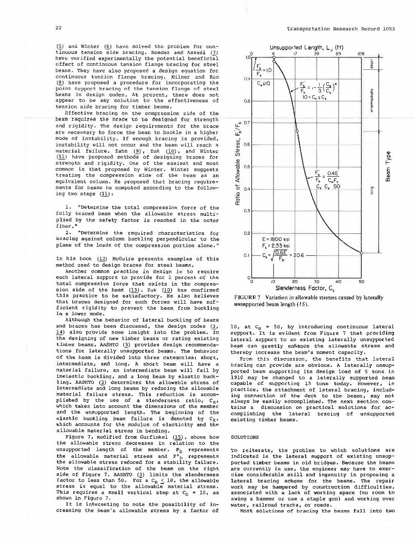
Figure 7, modified from Gurfinkel <! .. ~), shows how the allowable stress decreases in relation to the unsupported length of the member. Fb represents the allowable material stress and F'b represents the allowable stress reduced for a stability failure. Note the classification of the beam on the right side of Figure 7. AASHTO (3) limits the slenderness factor to less than 50. For a Cs < 10, the allowable stress is equal to the allowable material stress. This requires a small vertical step at Cs = 10, as shown in Figure 7.
It is interesting to note the possibility of increasing the beam's allowable stress by a factor of
Transportation Research Record 1053
Unsupported Length, Lu (ft) 0 4 17 39 69 109
1 .0·~--_,.,__ __ ~----------~
LC' 07 _ ...... LL""
vi IJ) 06 ~ (ii Q)
:l5 0 .. 5 c ~
.2 <i ...... 0 04 0
~ 0 .. 3
F' _A.=10 F . •
E = 1800 ksi F0 = 2.53 ksi
0.1 C, = ;o~E = 20.6 - ·l---+----1
10 20 30 40 50
Slenderness Factor, c. FIGURE 7 Variation in allowable stresses caused by laterally unsupported beam length (15).
Q) a. >-1-E c Q)
ID
10, at Cs = 50, by introducing continuous lateral support. It is evident from Figure 7 that providing lateral support to an existing laterally unsupported beam can greatly enhance the allowable stress and thereby increase the beam's moment capacity.
From this discussion, the benefits that lateral bracing can provide are obvious. A laterally unsupported beam supporting its design load of 5 tons in 1910 may be changed to a laterally supported beam capable of supporting 15 tons today. However, in practice, the attachment of lateral bracing, including connection of the deck to the beams, may not always be easily accomplished. The next section contains a discussion on practical solutions for accomplishing the lateral bracing of unsupported existing timber beams.
SOLUTIONS
To reiterate, the problem to which solutions are indicated is the lateral support of existing unsupported timber beams in old bridges. Because the beams are currently in use, the engineer may have to exercise considerable skill and ingenuity in proposing a lateral bracing scheme for the beams. The repair work may be hampered by construction difficulties, associated with a lack of working space (no room to swing a hammer or use a staple gun) and working over water, railroad tracks, or roads.
Most solutions of bracing the beams fall into two

Suprenant et al. 23
Nailing Bolting Reverse Bolting
Angles Friction
FIGURE 8 Deck-to-beam connections.
categories: deck-to-beam connections and beam-to-beam connections. Deck-to-beam connections include nailing, bolting, clip angles, and possibly a consideration of friction. Beam-to-beam connections include blocking, cross-bridging, and tension side bracing. Figures 8 and 9 show the possible connection techniques. All of these possible connections are discussed in the next two sections. No matter which connection technique is selected, the engineer should be careful to apply preservative treatment to any member that is penetrated. It does not make sense to solve one problem while creating another.
Deck-to-Beam Connections
Attaching the deck to the beams by nailing is analogous to attaching plywood floors to joists in house construction. This procedure can be an effective method of providing continuous lateral support. However, unlike houses, bridges experience vibration caused by vehicle traffic. It may be possible for the nails to "work out" from the beams. (This process has been witnessed by the senior author.) This is due to traffic moving across planks of different sizes and shapes, and unlevel deck bearing on the beams. This movement of the roadway deck tends to pry out the nails, making them more effective in puncturing tires than in providing lateral support. This effect can be even more pronounced if the roadway deck consists of two or more layers of different size and shape planks placed on top of each other. In one case, a 3-in. asphalt layer was placed over 2 layers of planks for a wearing surface. Because of the tilting and movement of the planks, the asphalt surface was broken up.
Bolting of the deck to the beam provides a greater resistance to uplift than nailing. However, depending on the degree of movement of the planks, the bolts may still be pried out.
Although bolting and nailing the deck to the beams is simple and may provide continuous lateral support, problems other than the "prying out" of the connectors may be encountered. It is not always an
~.-----~ ·--- -- ' .,, -- --· -... ~.
Blocking Cross-Bridging
Tension Side Bracing
FIGURE 9 Beam-to-beam connections.
easy task to make sure the nail or bolt enters the beam below, much less near the center of the beam. Also, deterioration or rotting of the deck and beam may reduce the effectiveness of the connection. Although it would be easy to distinguish deck deterioration, it would be difficult to check the condition of the beam-deck interface. It is likely, however, that the three problems associated with nailing and bolting the deck to the beams (prying out, missing the beam, and deck or beam deterioration) could be overcome by using an abundance of connectors. It is not a highly scientific solution, but it is economical and practical.
An interesting deck-to-beam connection may be a form of reverse bolting. The connectors would be bolted to the underside of the deck as shown in Figure a. The connectors should slide past the beam during movement. This requires that the unembedded portion of the bolt be long enough to maintain contact if the beam moves laterally. This type of connection does eliminate the three problems discussed for nailing and bolting.
Because it is possible to see where the bolt is being placed, there should be no problems with the connector not being adjacent to the beam. Also, it would be possible to check for deterioration of the deck at the proposed location of bolting. Beam deterioration would have little effect on the connection. As long as the connector slides past the beam for any upward deck movement, the aforementioned prying out of the bolt cannot occur. Also, the bolt (unless it protrudes through the deck surface) would not have any adverse effect on vehicle operating characteristics.
Certainly, the biggest construction problem associated with this connection is the cost of working underneath the bridge. A hanging scaffold may be required. Another problem is that of existing satisfactory performance. None of the authors have seen this type of connection used before and do not have any test results as to its actual field performance.
Another underside deck-to-beam connection is that which encompasses clip angles and bolts. This has all the advantages and disadvantages indicated for reverse bolting. This connection is more time consuming than reverse bolting, but it also provides a more positive connection. If the bridge was experiencing not only a lateral support problem, but also a problem of distributing wheel loads to beams, this connection would be b~tter than reverse bolting.
The discussion of a friction connection has been saved for last. It is doubtful that the friction between the deck and beam could account for the necessary lateral force to brace the beam. According to Zuk (10), the friction force would have to be 2 percent Of the total compressive force in the beam. This friction force would also have to be consistent over a long period of time. The bridge vibrations introduced by traffic would be enough to break any chemical adhesion or bonding between the deck and beam. Many designers have recommended against using

24
FIGURE 10 Weyerhaeuser deck bracket (1 6).
friction as lateral support between a concrete slab placed on steel beams for buildings. This situation would have a higher normal force (dead weight of concrete), a wider bearing area (concrete against steel flange) , and presumahly no vibration , Therefore, if friction is not considered as lateral support for beams in buildings, it definitely should not be considered as useful in bridge structures.
Another type of deck-to-beam connection is a deck bracket (Figure 10) manufactured and marketed by Weyerhaeuser < .. !§.>. This deck bracket, which is intended for use in panelized glued-laminated deck systems, could also be used to support a beam. This deck bracket, while bolted through the deck, is fitted into a routed groove on the beam (17). The formed teeth in the deck bracket firmly grip the beam and deck when the bolt is tightened. The deck bracket was developed to minimize deterioration resulting from connectors breaking through the treated envelope of members. Although it is not known whether this deck bracket has been used to provide lateral support of beams in existing bridges, it is a possibility. The biggest problem would be routing the groove in the side of the beam.
Beam-to-Beam Connec tions
AASHTO Ill currently requires timber beams in new bridges to have cross-hr idging. Figure 9 shows both cross-bridging and blocking, which can be used effectively to support beams. Blocking and crossbridging both must be applied under the bridge from hanging scaffolds. The biggest construction problem associated with both blocking and cross-bridging is fitting the new bracing between existing beams. Figure 11 shows the difficulty associated with blocking between timber and steel beams. (Note that this figure is for the bridge shown in Figures 1-3.) It took county personnel two weeks to install the blocking for these beams. It would be interesting to guess how effective this blocking is, due to the noticeable and unavoidable gaps between the blocking and beams. Note also how the distance varies between the beams, making field cuts of all blocking from the hanging scaffold a necessity.
Tension flange bracing as shown in Figure 12 would certainly speed up the construction process. The braces could be bolted into the bottom of the timber
FIGURE 11
Transportation Research Record 1053
Blocking between beams.
Deck \
Tension Flongo Bracing
Bottom of Timber Beoms
Truss Type Tension Flonge Bracing Section A-A
FIGURE 12 Tension side bracing.
members. A truss type configuration could be used as shown. This system could work well for a bridge that combines steel and timber beams. The tension side bracing could be bolted to the bottom of the timber beams and L-shaped bolts could be used to clamp on to the bottom flange of the beam. (See Figure s, which shows this type of clamp connection at the top of the steel flange.) Tension side bracing would be the easiest of the beam-to-beam type connectors to construct.
Unfortunately, the effectiveness of tension side bracing for timber beams has not yet been established technically. Therefore, it would be difficult to suggest a brace spacing to satisfy the lateral support requirements of the beam. Also, tension flange bracing could, during extremely high water, entangle objects floating in the water as they passed under the bridge.
CONCLUSION
Older bridges designed with long, laterally unsupported beams are not capable of carrying the truck
Suprenant et al.
loads currently imposed. The beams must be laterally braced to increase the load carrying capacity. There are methods available to calculate the strength and rigidity of lateral bracing. Current design codes enable the engineer to select the lateral brace spacing to achieve a given level of allowable stress.
The advantages and disadvantages of deck-to-beam connections and beam-to-beam connections are presented. Tension side bracing of beams may be an economical approach in the future, but no practical solution currently exists to determine the effectiveness of that bracing technique.
REFERENCES
1. W.A. Burr and M.S. Falk. The Design and Construction of Metallic Bridges. John Wiley and Sons, Inc., New York, 1905.
2. M. Merriman and H. Jacoby. Roofs and Bridges Part III, Bridge Design, 4th ed., John Wiley and Sons, Inc., New York, 1905.
3. Standard Specifications for Highway Bridges, 13th ed. AASHTO, Washington, D.C., 1983.
4. H.G. Allen and P.S. Bulson. Background to Buckling.McGraw-Hill, Inc., New York, 1980.
5. F. Bleich. Buckling Strength of Metal Structures.McGraw-Hill, Inc., New York, 1952.
6. G. Winter. Lateral Stability of Unsymmetrical I-Beams and Trusses in Bending. Transactions, ASCE, 1943.
7. c.w. Roeder and M. Assadi. Later~l Stability of
25
I-Beams with Partial Support. Journal of the Structural Division, Vol. 108, No. ST8, ASCE, Aug. 1982.
8. H.R. Milner and S.N. Rao. The Design of Tension Flange Btaced Beams. Instability and Plastic Collapse of Steel Structures (L.J. Morris, ed.), Granada Publishing Limited, New York, 1983.
9. J.J. Zahn. Bracing Requirements for Lateral Stability. Journal of Structural Engineering, Vol. 110, No. 8, Aug. 1984.
10. w. Zuk. Lateral Bracing Forces on Beams and Columns. Journal of Engineering Mechanics Division, Vol. 82, No. EM3, ASCE, July 1956.
11. G. Winter. Lateral Bracing of Columns and Beams. Journal of the Structural Division, ASCE, March 1958.
12. w. McGuire. Steel Structures. Prentice-Hall, Inc., Englewood Cliffs, N.J., 1968.
13. Guide to Stability Design Criteria for Metal Structures, 3rd ed. (B.G. Johnson, ed.), John Wiley and Sons, Inc., New York, 1976.
14': Timber Construction Manual, 2nd ed. American Institute of Timber Construction, John Wiley and Sons, Inc., New York, 1974.
15. _G. Gurfinkel. Wood Engineering. Southern Forest Products Association, New Orleans, La., 1973.
16. M.F. Stone. New Concept Design for Glulam Timber Bridges. Weyerhaeuser, Inc., Tacoma, Wash., 1978.
17. R.M. Gutkowski and T.G. Williamson. Timber Bridges: State-of-the-Art. Journal of Structural Engineering, Vol. 109, No. 9, Sept. 1983.