laube technology pcb relays · laube technology pcb relays contact form current part series page...
TRANSCRIPT

LAUBE TECHNOLOGY
PCB RELAYS
CONTACT FORM CURRENT PART SERIES PAGE #'S
(1A) SPST-NO 5 TRJV 28~30 (Link)
(1A) SPST-NO 10 TRG1 31~33 (Link)
(1A) SPST-NO 12 TRA1 34~36 (Link)
(1A) SPST-NO 12 TRA4 43~45 (Link)
(1A) SPST-NO 15 HJR-21FF 22~24 (Link)
(1A) SPST-NO 15 HJR-3FF 19~21 (Link)
(1A) SPST-NO 20 TRA2 37~39 (Link)
(1A) SPST-NO 25 HJR-78F 25~27 (Link)
(1C) SPDT 10 TRG1 31~33 (Link)
(1C) SPDT 12 TRA1 34~36 (Link)
(1C) SPDT 15 HJR-21FF 22~24 (Link)
(1C) SPDT 20 TRA2 37~39 (Link)
(1C) SPDT 25 HJR-78F 25~27 (Link)
(2A) 2-SPST-NO 8 TRA3 40~42 (Link)
(2A) 2-SPST-NO 7 TRA5 46~48 (Link)
(2C) DPDT 8 TRA3 40~42 (Link)
18

HJR-3FFSPECIFICATION
FILE NUMBER: P-08KA501A
DATE: 2001/11/02
Features
10A switching capability
Small footprint
Sealed type available
CONTACT DATA
Contact Form 1A/1C
Contact Material AgCdO AgSnO
Contact Ratings
1A:10A 240VAC,
15A 12VDC(TUV)
12A 120VAC/24VDC
1C: 7A 240VAC/10A 120VAC/24VDC
5A 240VAC(TUV)
Max Switching Voltage 250VAC/30VDC
Max Switching Current 15A
Max Switching Power 2770VA/240W
Contact Resistance 100m Max at 6VDC 1A
Life Expectancy Electrical 100,000 Operations(at 30 Operations/min.)
Mechanical 10,000,000 Operations
GENERAL DATA
Insulation Resistance 100M Min at 500VDC
Dielectric Strength Between Open Contacts 750VAC(for one minute)
Between Contacts and coil 1500VAC(for one minute)
Operate Time 10ms
Release Time 5ms
Temperature Range -40oC to+70 oC
Operating Extremes 10G Shock Resistance
Damage Limits 100G
Vibration Resistance 10-50Hz 1.5mm
Humidity 40—85%
Weight Approx 10g
Safety Standard UL:E 173485 TUV:R 9859574,CH0062184-2001
Laube Technology HJR-3FF
19

COIL DATA
Coil Resistance at20±10%( )NominalVoltage
(VDC) 0.36W 0.45W
Max Operate Voltage
VDC
Min ReleaseVoltage
VDC
Max ApplicableVoltage
VDC
3 25 2.25 0.3 3.9
5 70 3.75 0.5 6.5
6 100 4.5 0.6 7.8
9 225 6.75 0.9 11.7
12 400 9 1.2 15.6
18 900 13.5 1.8 23.4
24 1600 18 2.4 31.2
48 6400 ±15% 5100 ±15% 36 4.8 62.4
ORDERING CODE
HJR-3FF--12VDC-S---Z
Z Form C
H Form A
Sealed
Coil Nominal Voltage
Relay Model
Laube Technology HJR-3FF
20

OVERALL AND MOUNTING DIMENSIONS
Laube Technology HJR-3FF
21

HJR-21FFSPECIFICATION
FILE NUMBER: P-08KA601A
DATE: 2001/11/02
Features
10A switching capability
SPST-NO configuration
Small footprint
Sealed version available
CONTACT DATA
Contact Form 1A/1C
Contact Material AgCdO AgSnO
Contact Ratings
1A:12A 240VAC
15A 12VDC(TUV)
15A 120VAC/24VDC
1C:10A 240VAC/12A 120VAC/240VDC
7A 240VAC(TUV)
Max Switching Voltage 250VAC/30VDC
Max Switching Current 15A
Max Switching Power 2770VA/240W
Contact Resistance 100m Max at 6VDC 1A
Life Expectancy Electrical 100,000 Operations(at 30 Operations/min.)
GENERAL DATA
Insulation Resistance 100M Min at 500VDC
Dielectric Strength Between Open Contacts 750VAC(for one minute)
Between Contacts and coil 1500VAC(for one minute)
Operate Time 10ms
Release Time 5ms
Temperature Range -40oC to+70 oC
Operating Extremes 10G Shock Resistance
Damage Limits 100G
Vibration Resistance 10-55Hz,1.5mm
Humidity 40-85%
Weight Approx 13g
Safety Standard TUV R9859574 UL:E173485, CH0062182-2001
Laube Technology HJR-21FF
Mechanical 10,000,000 Operations
22

COIL DATA
Coil Resistance at20±10%( )NominalVoltage
(VDC) 0.36W 0.45W
Max Operate Voltage
VDC
Min ReleaseVoltage
VDC
Max ApplicableVoltage
VDC
3 25 2.25 0.3 3.9
5 70 3.75 0.5 6.5
6 100 4.5 0.6 7.8
9 225 6.75 0.9 11.7
12 400 9 1.2 15.6
24 1600 18 2.4 31.2
48 6400±15% 5100±15% 36 4.8 62.4
ORDERING CODE
HJR-21FF---12VDC--S--H
Z Form C
H Form A
Sealed
Coil Nominal Voltage
Relay Model
Laube Technology HJR-21FF
23
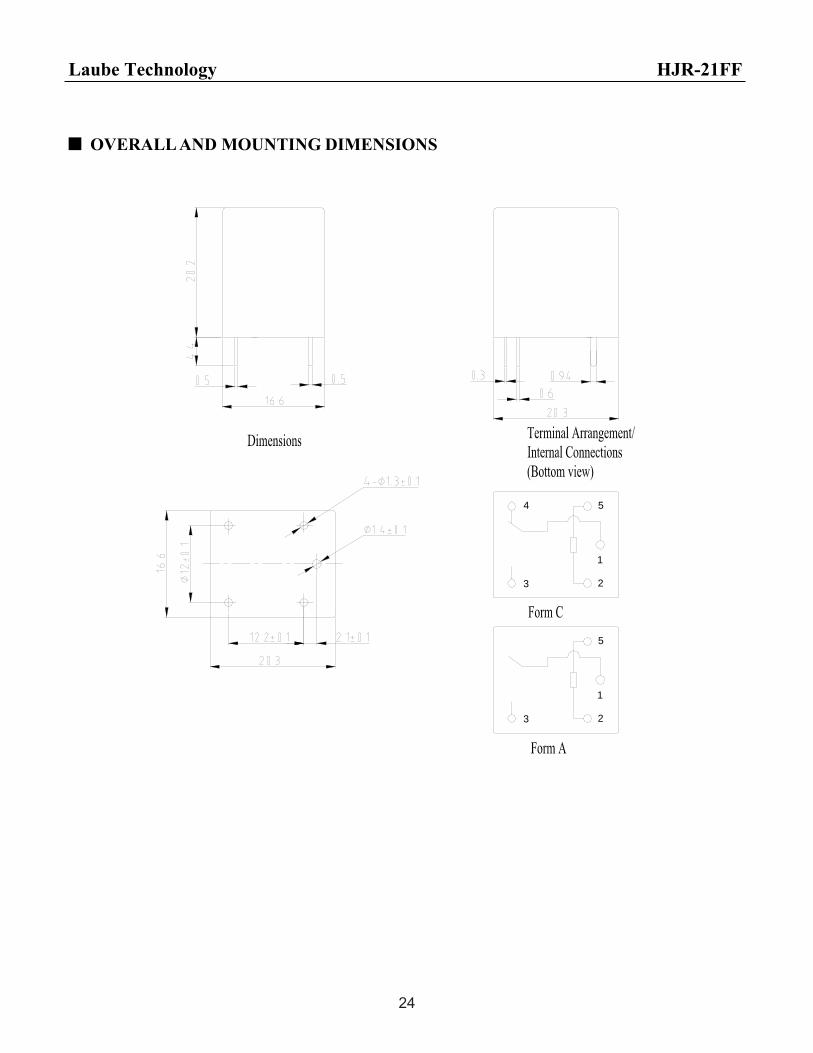
OVERALL AND MOUNTING DIMENSIONS
3 2
1
5
3
4
1
2
5
Laube Technology HJR-21FF
24

HJR-78F(TRKM)SPECIFICATION
FILE NUMBER: P-08KE201A
DATE: 2001/11/02
Features
20A switching capability
Small size auto relay
CONTACT DATA
Contact Form 1A/1C
Contact Material AgNi, AgSnO
Contact Ratings NC:20A14VDC NC:12A/14VDC 1C:7A 120VAC
Max Switching Voltage 16VDC
Max Switching Current 25A
Max Switching Power 400W,840VA
Contact Resistance 100m Max at 6VDC 1A
Life Expectancy Electrical 100,000 Operations(at 30 Operations/min.)
Mechanical 10,000,000 Operations
GENERAL DATA
Insulation Resistance 100M Min at 500VDC
Dielectric Strength Between Open Contacts 500VAC(for one minute)
Between Contacts and coil 500VAC(for one minute)
Operate Time 10ms
Release Time 5ms
Temperature Range -40oC to+85oC
Operating Extremes 10GShock Resistance
Damage Limits 100G
Vibration Resistance 10-55Hz,2.0mm
Humidity 35-85%
Weight Approx. 6g
Safety Standard UL:E173485
Laube Technology HJR-78F(TRKM)
25

COIL DATA
Coil Resistance at20±10%( )NominalVoltage
(VDC) 0.6W 0.8W
Max Operate Voltage
(VDC)
Min ReleaseVoltage
(VDC)
Max ApplicableVoltage
(VDC)
6 60 45 3.9 0.48 7.8
9 135 100 5.85 0.72 11.7
12 240 180 7.8 0.96 15.6
24 960 720 15.6 1.92 31.2
ORDERING CODE
HJR-78F(TRKM) D--12VDC--S--Z
Z Form C
H Form A
Sealed
Coil Nominal Voltage
D=0.8W Coil Power
L=0.6W
Relay Model
Laube Technology HJR-78F(TRKM)
26

OVERALL AND MOUNTING DIMENSIONS
Laube Technology HJR-78F(TRKM)
27
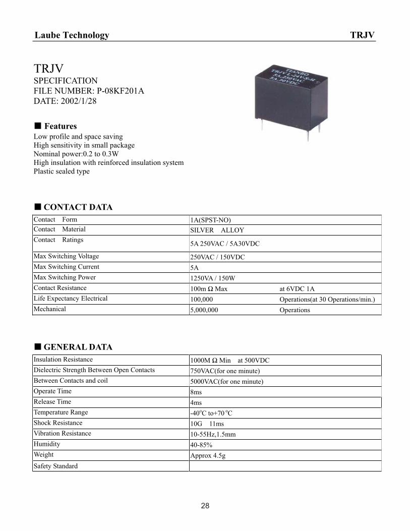
TRJVSPECIFICATION
FILE NUMBER: P-08KF201A
DATE: 2002/1/28
Features
Low profile and space saving
High sensitivity in small package
Nominal power:0.2 to 0.3W
High insulation with reinforced insulation system
Plastic sealed type
CONTACT DATA
Contact Form 1A(SPST-NO)
Contact Material SILVER ALLOY
Contact Ratings 5A 250VAC / 5A30VDC
Max Switching Voltage 250VAC / 150VDC
Max Switching Current 5A
Max Switching Power 1250VA / 150W
Contact Resistance 100m Max at 6VDC 1A
Life Expectancy Electrical 100,000 Operations(at 30 Operations/min.)
Mechanical 5,000,000 Operations
GENERAL DATA
Insulation Resistance 1000M Min at 500VDC
Dielectric Strength Between Open Contacts 750VAC(for one minute)
Between Contacts and coil 5000VAC(for one minute)
Operate Time 8ms
Release Time 4ms
Temperature Range -40oC to+70 oC
Shock Resistance 10G 11ms
Vibration Resistance 10-55Hz,1.5mm
Humidity 40-85%
Weight Approx 4.5g
Safety Standard
Laube Technology TRJV
28

COIL DATA
Coil Resistance at20±10%( )NominalVoltage
(VDC) 0.2W 0.3W
Max Operate Voltage
(VDC)
Min ReleaseVoltage
(VDC)
Max ApplicableVoltage
(VDC)
3 45 30 2.25 0.15 3.9
5 125 83 3.75 0.25 6.5
6 180 120 4.5 0.3 7.8
9 405 270 6.75 0.45 11.7
12 720 480 9 0.6 15.6
18 1620 1080 13.5 0.9 23.4
24 2880 1920 18 1.2 31.2
48 0.36W 6400±15%( ) 36 2.4 62.4
ORDERING CODE
TRJV D--12VDC--S--H
H Form A
Sealed
Coil Nominal Voltage
D=0.3W L=0.2W
Relay Model
Laube Technology TRJV
29

OVERALL AND MOUNTING DIMENSIONS
Laube Technology TRJV
30

TRG1SPECIFICATION
FILE NUMBER: P-08KB101A
DATE: 2001/11/02
Features
10A switching capability
SPST-NO & SPDP configuration
Standard PC layout
Sealed type available
CONTACT DATA
Contact Form 1A/1C
Contact Material AgCdO AgSnO
Contact Ratings 1A:10A/120VAC 5A/240VAC/30VDC
1A-L,1C:3A 240VAC/30VDC
Max Switching Voltage 250VAC/30VDC
Max Switching Current 10A
Max Switching Power 1200VA/150W
Contact Resistance 100M max at 6VDC 1A
Life Expectancy Electrical 100,000 Operations(at 30 Operations/min.)
Mechanical 10,000,000 Operations
GENERAL DATA
Insulation Resistance 100M Min at 500VDC
Dielectric Strength Between Open Contacts 750VAC(for one minute)
Between Contacts and coil 2500VAC(for one minute)
Operate Time 8ms
Release Time 5ms
Temperature Range -40oC to+70oC
Operating Extremes 10GShock Resistance
Damage Limits 100G
Vibration Resistance 10-55Hz,1.5mm
Humidity 40-85%
Weight Approx 6g
Safety Standard UL: E173485, CH0062183-2001
Laube Technology TRG1
31

COIL DATA
Coil Resistance at20±10%( )NominalVoltage
(VDC) 0.2W 0.45W
Max Operate Voltage
VDC
Min ReleaseVoltage
VDC
Max ApplicableVoltage
VDC
3 45 20 2.25 0.3 3.9
5 125 56 3.75 0.5 6.5
6 180 80 4.5 0.6 7.8
9 405 180 6.75 0.9 11.7
12 720 320 9 1.2 15.6
24 2880 1280 18 2.4 31.2
48 5100±15% 36 4.8 62.4
ORDERING CODE
TRG1 D--12VDC--S--Z
Z Form C
H Form A
Sealed
Coil Nominal Voltage
D=0.45W Coil Power
L=0.2W
Relay Model
Laube Technology TRG1
32
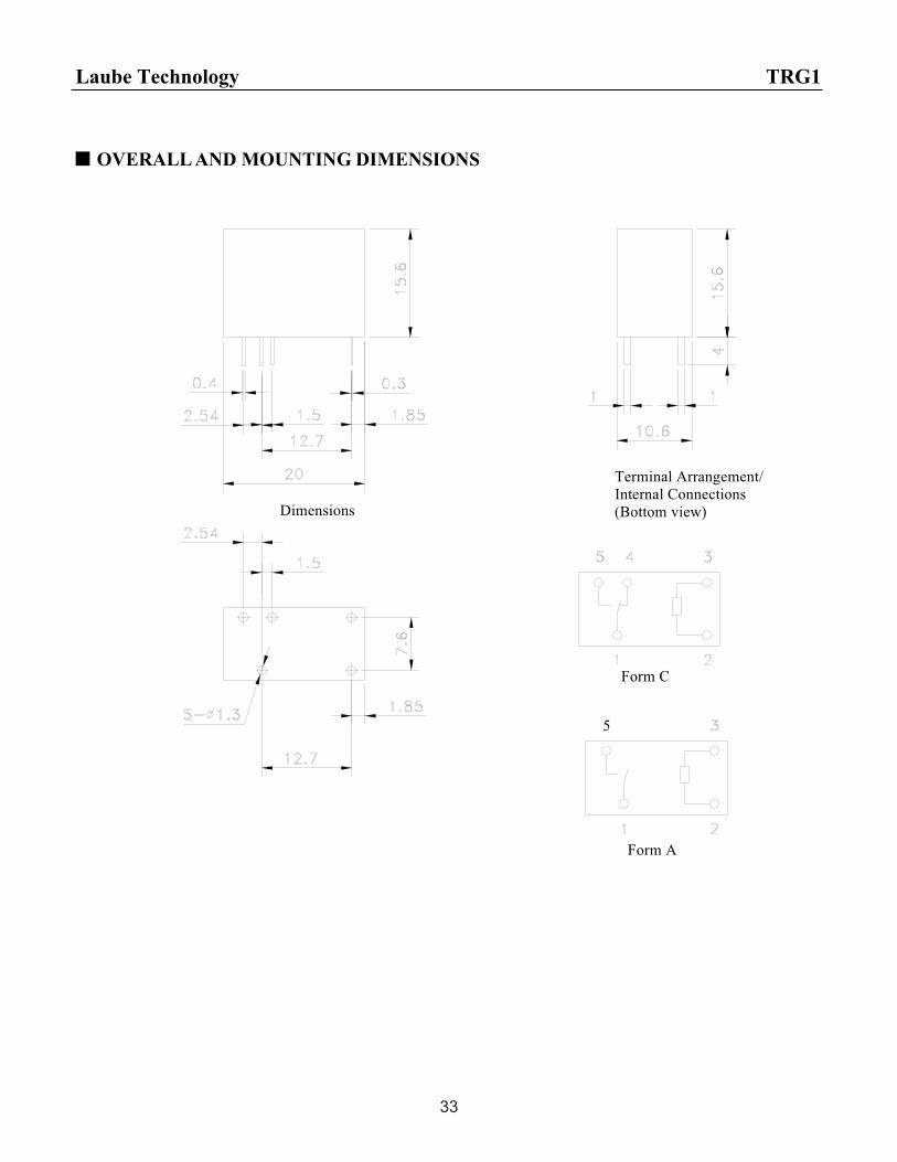
OVERALL AND MOUNTING DIMENSIONS
Dimensions
Terminal Arrangement/
Internal Connections
(Bottom view)
Form C
Form A
5
Laube Technology TRG1
33

TRA1SPECIFICATION
FILE NUMBER: P-08KC101A
DATE: 2001/11/02
Features
10A switching capability
SPST-NO & SPDP configuration
Small footprint
Sealed version available
CONTACT DATA
Contact Form 1A/1C
Contact Material AgCdO AgSnO
Contact Ratings 10A 240VAC 10A 30VDC
Max Switching Voltage 250VAC/30VDC
Max Switching Current 12A
Max Switching Power 2500VA/300W
Contact Resistance 100m Max at 6VDC 1A
Life Expectancy Electrical 100,000 Operations(at 30 Operations/min.)
Mechanical 10,000,000 Operations
GENERAL DATA
Insulation Resistance 100M Min at 500VDC
Dielectric Strength Between Open Contacts 1000VAC(for one minute)
Between Contacts and coil 5000VAC(for one minute)
Operate Time 20ms
Release Time 10ms
Temperature Range -30oC to+70 oC
Operating Extremes 10G Shock Resistance
Damage Limits 100G
Vibration Resistance 10-55Hz,1.5mm
Humidity 40-85%
Weight Approx 14g
Safety Standard UL:E173485
Laube Technology TRA1
34

COIL DATA
Coil Resistance at20±10%( )NominalVoltage
(VDC) 0.54W 0.72W
Max Operate Voltage
VDC
Min ReleaseVoltage
VDC
Max ApplicableVoltage
VDC
3 17 13 2.4 0.15 3.9
5 46 35 4 0.25 6.5
6 67 50 4.8 0.3 7.8
9 150 110 7.2 0.45 11.7
12 270 200 9.6 0.6 15.6
24 1050 800 19.2 1.2 31.2
48 4250±15% 3200 38.4 2.4 62.4
ORDERING CODE
TRA1 D--12VDC—S--Z
Z Form C
H Form A
Sealed
Coil Nominal Voltage
D=0.72W Coil Power
L=0.54W
Relay Model
Laube Technology TRA1
35

OVERALL AND MOUNTING DIMENSIONS
Dimensions
Terminal Arrangement/
Internal Connections
(Bottom view)
Laube Technology TRA1
Form C
Form A
5
36
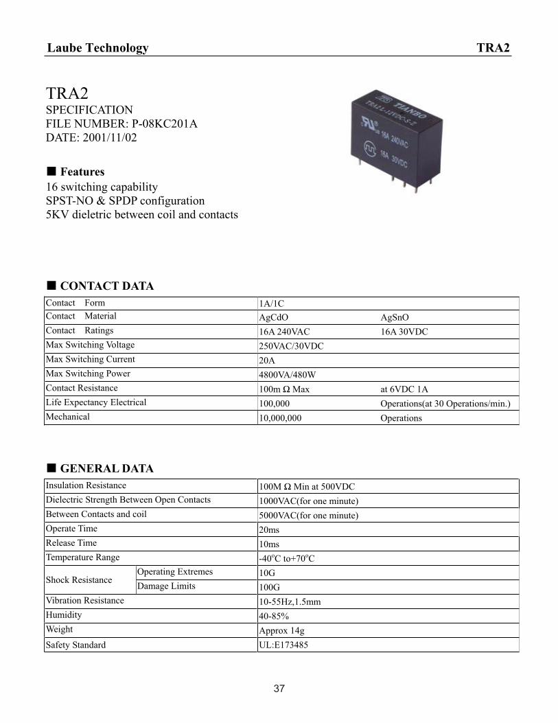
TRA2SPECIFICATION
FILE NUMBER: P-08KC201A
DATE: 2001/11/02
Features
16 switching capability
SPST-NO & SPDP configuration
5KV dieletric between coil and contacts
CONTACT DATA
Contact Form 1A/1C
Contact Material AgCdO AgSnO
Contact Ratings 16A 240VAC 16A 30VDC
Max Switching Voltage 250VAC/30VDC
Max Switching Current 20A
Max Switching Power 4800VA/480W
Contact Resistance 100m Max at 6VDC 1A
Life Expectancy Electrical 100,000 Operations(at 30 Operations/min.)
Mechanical 10,000,000 Operations
GENERAL DATA
Insulation Resistance 100M Min at 500VDC
Dielectric Strength Between Open Contacts 1000VAC(for one minute)
Between Contacts and coil 5000VAC(for one minute)
Operate Time 20ms
Release Time 10ms
Temperature Range -40oC to+70oC
Operating Extremes 10GShock Resistance
Damage Limits 100G
Vibration Resistance 10-55Hz,1.5mm
Humidity 40-85%
Weight Approx 14g
Safety Standard UL:E173485
Laube Technology TRA2
37

COIL DATA
Coil Resistance at20±10%( )NominalVoltage
(VDC) 0.54W 0.72W
Max Operate Voltage
VDC
Min ReleaseVoltage
VDC
Max ApplicableVoltage
VDC
3 17 13 2.4 0.15 3.9
5 46 35 4 0.25 6.5
6 67 50 4.8 0.3 7.8
9 150 110 7.2 0.45 11.7
12 270 200 9.6 0.6 15.6
24 1050 800 19.2 1.2 31.2
48 4250±15% 3200 38.4 2.4 62.4
ORDERING CODE
TRA2 D--12VDC--S--Z
Z Form C
H Form A
Sealed
Coil Nominal Voltage
D=0.72W Coil Power
L=0.54W
Relay Model
Laube Technology TRA2
38

OVERALL AND MOUNTING DIMENSIONS
Laube Technology TRA2
Dimensions
Terminal Arrangement/
Internal Connections
(Bottom view)
Form C
Form A
5
39

TRA3SPECIFICATION
FILE NUMBER: P-08KC301A
DATE: 2001/11/02
Features
Creepage distance: 8.0mm Min
Au-clad contact available
CONTACT DATA
Contact Form 2A/2C
Contact Material AgCdO AgSnO
Contact Ratings 5A 240VAC 5A 30VDC
Max Switching Voltage 250VAC/30VDC
Max Switching Current 8A
Max Switching Power 1250VA/240W
Contact Resistance 100m Max at 6VDC 1A
Life Expectancy Electrical 100,000 Operations(at 30 Operations/min.)
Mechanical 10,000,000 Operations
GENERAL DATA
Insulation Resistance 100M Min at 500VDC
Dielectric Strength Between Open Contacts 1000VAC(for one minute)
Between Contacts and coil 5000VAC(for one minute)
Operate Time 20ms
Release Time 10ms
Temperature Range -30oCto+70 oC
Operating Extremes 10GShock Resistance
Damage Limits 100G
Vibration Resistance 10-55Hz,1.5mm
Humidity 40-85%
Weight Approx 14g
Safety Standard UL:E173485
Laube Technology TRA3
40
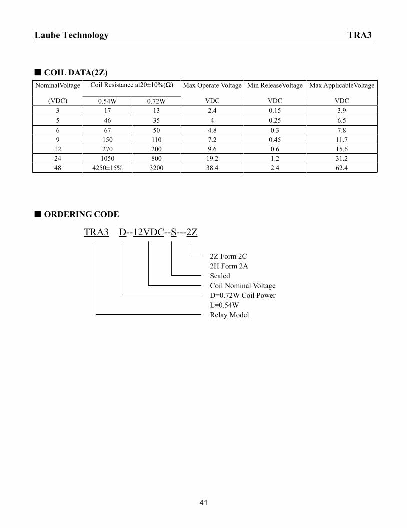
COIL DATA(2Z)
Coil Resistance at20±10%( )NominalVoltage
(VDC) 0.54W 0.72W
Max Operate Voltage
VDC
Min ReleaseVoltage
VDC
Max ApplicableVoltage
VDC
3 17 13 2.4 0.15 3.9
5 46 35 4 0.25 6.5
6 67 50 4.8 0.3 7.8
9 150 110 7.2 0.45 11.7
12 270 200 9.6 0.6 15.6
24 1050 800 19.2 1.2 31.2
48 4250±15% 3200 38.4 2.4 62.4
ORDERING CODE
TRA3 D--12VDC--S---2Z
2Z Form 2C
2H Form 2A
Sealed
Coil Nominal Voltage
D=0.72W Coil Power
L=0.54W
Relay Model
Laube Technology TRA3
41

OVERALL AND MOUNTING DIMENSIONS
Form A
4
Form C
Dimensions
Terminal Arrangnment/
Internal Connections
(Bottom view)
Laube Technology TRA3
42

TRA4SPECIFICATION
FILE NUMBER: P-08KB201A
DATE: 2001/7/19
Features
1 form A contact arrangement
Immersion cleanable, sealed version available
Applications include appliance, HAVC, CTV,
Monitor, Emergency lighting
CONTACT DATA
Contact Form 1A
Contact Material AgSnO
Contact Ratings 10A 250VAC/30VDC
Max Switching Voltage 250VAC/110VDC
Max Switching Current 12A
Max Switching Power 2500VA/300W
Contact Resistance 100m Max at 6VDC 1A
Life Expectancy Electrical 100,000 Operations(at 30 Operations/min.)
Mechanical 10,000,000 Operations
GENERAL DATA
Insulation Resistance 100M Min at 500VDC
Dielectric Strength Between Open Contacts 1000VAC(for one minute)
Between Contacts and coil 4000VAC(for one minute)
Operate Time 20ms
Release Time 10ms
Temperature Range -40oC to+70 oC
Operating Extremes 10GShock Resistance
Damage Limits 100G
Vibration Resistance 10-55Hz,1.5mm
Humidity 20-85%
Weight Approx 11g
Safety Standard
Laube Technology TRA4
43

COIL DATA
Coil Resistance at20±10%( )NominalVoltage
(VDC) 0.25W 0.54W
Max Operate Voltage
VDC
Min ReleaseVoltage
VDC
Max ApplicableVoltage
VDC
3 36 16.7 2.25 0.3 3.9
5 100 46.3 3.75 0.5 6.5
6 144 66.7 4.5 0.6 7.8
9 324 150 6.75 0.9 11.7
12 576 266.7 9 1.2 15.6
24 2304 1066.7 18 2.4 31.2
48 9216±15% 4266.7±15% 36 4.8 62.4
ORDERING CODE
TRA4 D--12VDC--S--H
H Form A
Sealed
Coil Nominal Voltage
D=0.54W Coil Power
L=0.25W
Relay Model
Laube Technology TRA4
44

Terminal Arrangement/
Internal Connections
(Bottom view)Dimensions
OVERALL AND MOUNTING DIMENSIONS
Laube Technology TRA4
45

TRA5SPECIFICATION
FILE NUMBER: P-08KB301A
DATE: 2001/7/19
Features
2 form A contact arrangement
Immersion cleanable, sealed version available
Meet 3000V dieletrie voltage between coil and
contacts (1.2/50us)
CONTACT DATA
Contact Form 2A
Contact Material AgSnO
Contact Ratings 3A 125VAC/24VDC 5A 250VAC/30VDC
Max Switching Voltage 250VAC/30VDC
Max Switching Current 7A
Max Switching Power 1250VA/150W
Contact Resistance 100m Max at 6VDC 1A
Life Expectancy Electrical 100,000 Operations(at 30 Operations/min.)
Mechanical 10,000,000 Operations
GENERAL DATA
Insulation Resistance 100M Min at 500VDC
Dielectric Strength Between Open Contacts 1000VAC(for one minute)
Between Contacts and coil 4000VAC(for one minute)
Operate Time 20ms
Release Time 10ms
Temperature Range -40oC to+70 oC
Operating Extremes 10GShock Resistance
Damage Limits 100G
Vibration Resistance 10-55Hz,1.5mm
Humidity 20-85%
Weight Approx 13g
Safety Standard
Laube Technology TRA5
46

COIL DATA
Coil Resistance at20±10%( )NominalVoltage
(VDC) 0.25W 0.54W
Max Operate Voltage
VDC
Min ReleaseVoltage
VDC
Max ApplicableVoltage
VDC
3 36 16.7 2.25 0.3 3.9
5 100 46.3 3.75 0.5 6.5
6 144 66.7 4.5 0.6 7.8
9 324 150 6.75 0.9 11.7
12 576 266.7 9 1.2 15.6
24 2304 1066.7 18 2.4 31.2
48 9216±15% 4266.7±15% 36 4.8 62.4
ORDERING CODE
TRA5 D--12VDC--S---H
H Form A
Sealed
Coil Nominal Voltage
D=0.54W Coil Power
L=0.25W
Relay Model
Laube Technology TRA5
47

Dimensions
Terminal Arrangement/
Internal Connections
(Bottom view)
OVERALL AND MOUNTING DIMENSIONS
Laube Technology TRA5
48