launceston - a city on a floodplain …floodplainconference.com/papers2013/andrew fullard full...
TRANSCRIPT

1
LAUNCESTON - A CITY ON A FLOODPLAIN PROTECTING LAUNCESTON FROM A 1 IN 200 ARI FLOOD
A Fullard1 1Launceston Flood Authority, Launceston, TAS
Introduction Launceston is a city of some 70,000 people, with a portion of its CBD and major northern suburb, Invermay, situated on the natural floodplain at the confluence of the Tamar River estuary and the North and South Esk Rivers. Much of Invermay is below the high tide level and is reliant upon levees for its sustainability. Refer Figure 1 for extent of Launceston's flooding if levee were not present. The Invermay area is now considered a desirable inner city suburb populated by a large number of young and middle-aged people indicating its potential for growth. Much of Launceston's cultural centre, including Launceston's Museum, Aurora Sports Stadium, and campuses of the University of Tasmania, are located there. The flood prone area of the CBD is a mixture of residential and commercial enterprises and is home to Boags Brewery and historic buildings associated with Launceston's port history. Launceston has been subject to 35 significant floods since records began, with the 1929 flood reputedly being the worst, displacing over 4000 residents and rendering many buildings uninhabitable. Much of the lower CBD was also inundated during this flood. Two floods in 1852 and 1863 are recorded to be higher than the 1929 flood; however the 1929 flood had the most severe consequences and is etched into the history of Launceston.
Figure 1 - Launceston's CBD and suburb of Invermay inundation area without levees.

2
Following a significant design report by the Launceston Flood Protection Authority in 1959 (Munro, 1959), a levee system was constructed during the following decade to protect the CBD and Invermay. Due to the deep sediments that provide a poor foundation, those levees subsided and deteriorated over the next four decades to a point where the protection provided by the system was significantly lower than its intended design. Context The Tamar River estuary is 70 kilometres long extending south from Bass Straight to where Launceston is located at its upper reaches. It is described as a flooded river valley being inundated during the last post glacial transgression that occurred between 13,500 to 6,500 years ago. The two major tributaries of the Tamar River estuary are the South Esk and North Esk Rivers. The catchment of these two rivers amount to over 10,000 km2, being approximately one sixth of the land mass of Tasmania. The South Esk is the longest river in Tasmania (252km) and is the main source of fresh water to the estuary. Its annual mean flow is approximately 70 cumecs (RDCP 2003) and has a calculated probable maximum flow of 7,000 cumecs (Munro, 1959 & Foster et al. 1986). The semi-diurnal tide in Bass Straight at the entrance, with a range of approximately 2.3m, undergoes a transformation through amplification and asymmetry as it progresses up the estuary to have a range at Launceston of approximately 3.3m with a shorter flood tide period than its ebb tide period (BMT WMB Aug 2009). This transformation impacts the floods that the city experiences.
The Launceston flood protection system Following the impact of the 1929 flood, the Tasmanian State Government set-about to make sure that a disaster of that nature never would reoccurr, and after the interruption of the Second World War, brought about Act No. 43 of 1955 with the flowing objectives:
"(a) To investigate flooding at or near the confluence of the North Esk and South
Esk Rivers and measures to mitigate it,
(b) Prepare a scheme to provide protection from flooding for low lying lands in the
vicinity in such detail and with such plans and estimates as it thinks fit."
As a consequence, the Launceston Flood Protection Authority was established in 1956. In 1957, Professor C.H. Munro was appointed as Principal Executive Officer and together with support staff commenced their investigations. In September 1959, Munro and his colleges submitted their final report (Munro 1959) that met the objectives of Act No. 43 of 1955. Munro et al had undertaken research into the river flows, flood events, rainfall history and patterns, riverbed morphology and constructed a scale model whereby they established flood heights for the range of river flows and defined the principles of a levee system to protect Invermay and the low lying areas of the CBD. Their research indicated that the flows of the South Esk River during the 1929 flood were approximately 150,000 cusecs (4,250 cumecs) and that the river's probable maximum flow was in the order of 250,000 cusecs (7,000 cumecs). It was

3
recommended a levee system be designed to protect from the probable maximum flood (PMF). During the early 1960's a ten kilometre levee system was designed to mitigate the PMF and land was procured. Construction commenced in the mid-1960's and continued for the next decade (Figure 2). Construction of the earth levees was staged allowing for settlement over a period of years before the Invermay sediments would support the final levee height.
Figure 2 - Munro (1959) (colour edited)
In some areas, particularly around the Invermay Railyards, following a substantial river bank failure in 1965 (Figure 3), earth levees were abandoned in favour of concrete levees founded on timber piles driven deep into the sediments. Ideally the piles were to have been driven into the solid material underlying the sediments; however in some sections this was not achieved resulting in the levee being unserviceable by today's standards. The earth levees continue to settle to this day. In 2005, after many years of insufficient maintenance, engineers reassessed the levee system and concluded it was no longer fit for purpose providing a lower level of protection than required.

4
Figure 3 - Photo of the 1965 river bank slip at Invermay Railyards
Review of the flood frequency curve A report in 1992 by the Hydro-Electric Commission (now Hydro Tasmania Consulting) and the Bureau of Meteorology revised the design hydrology for Launceston (HEC, 1992), which resulted in a significant increase in the design flood peak flows. WRL was engaged in 1992 to reassess the level of protection provided by the levees at that time (WRL, 1992) based on HEC, 1992 and found that the scheme would protect from a 100 ARI event but be overtopped by a 200 year ARI event. These results had significant financial implications for the maintenance/reconstruction of the levee system. In 2008, Hydro Tasmania Consulting was engaged by Launceston City Council to review the flood frequency curve for the Trevallyn Dam inflows (Hydro, 2008). The Trevallyn Dam is located on the South Esk River approximately three kilometres upstream from Launceston and provided an historical and geographical context for the review. The main items covered in the flood frequency review included:
• An investigation of the flood peak series used in previous reports and revision as required. This included flood peak estimates from the 19th
century.
• Modification of existing rainfall run-off models to allow a Monte-Carlo analysis to be undertaken investigating variability in initial losses and rainfall temporal patterns.
• Production of new flood frequency estimates based on revised model results and historic data series, including the 1:200 Annual Exceedence Probability (AEP) flood peak.

5
Two historic flood series were identified for the study. The first being historic peaks from the 1800s (19th century) and the second a continuous series from 1901 to 2007 derived for the South Esk from Launceston gauging station and Trevallyn Pond spill data. A RORB model was developed from the model definition of an earlier 2003 Hydstra Model (Cox, 2003) and contained all ratings, reach lengths and sub area sizes as the 2003 Hydstra model. Adopted model parameters of channel lag, initial loss and continuing loss were established. After establishing Intensity-frequency-duration (IFD) rainfalls for the Trevallyn catchment and extracting representational temporal patterns from the South Esk at Llewellyn rain recorders (mid South Esk catchment), Monte-Carlo analysis was undertaken using the RORB and Hydstra models: RORB for AEPs less extreme than 1:200 and Hydstra for AEPs more extreme than 1:200. The critical duration of both models was observed at 72 hours. Flood frequency curves were developed using the 1800s data and without the 1800s data. It was found the influence of the 1800s data resulted in a significant increase in the flood peaks. When the stochastic results of the RORB and Hydstra models were plotted on the flood frequency curves the best fit was without the 1800s data (Figure 4).
Figure 4 - Flood Frequency with Stochastic Model Results
Consequently Peak Flood estimates were adopted without the 1800s data (Figure 5) resulting in a reduced Recurrence Interval for a given flood flow. This was concerning as there was a community expectation that the level of flood protection would match that of the 1929 flood. This study also concluded the PMF was 11,000 cumecs as compared to the previous estimation of a PMF of 7,000 cumecs.

6
Figure 5 - Annual Recurrence Intervals (ARI) before and after the 2008 review with recorded floods over
1000 cumecs
Establishing flood heights Having re-established the flood frequency curve, BMT WBM (2008) was engaged to principally revise the flood level contours for floods impacting Launceston. The full objectives of the study were to:
• Develop a 2D hydraulic model of the River Tamar and the lower reaches of the North and South Esk rivers;
• Calibrate the model to the 1969 flood event;
• Prepare revised flood level contours for the 20, 50, 100, 200 and 500 year average recurrence interval (ARI) design floods;
• Assess the impact of ocean level change scenarios on flood levels;
• Prepare a report documenting the methodology and findings. A digital elevation model (DEM) was developed using sources including, navigation charts, photogrammetric data of intertidal mudflats, bathymetric surveys of the Home Reach and North Esk River cross-sections collected from 2005. For the study, the design event hydrology was provided by the Launceston City Council and based on the Hydro (2008) and WRL (2006). Using these reports the design flow was considerably lower than previously adopted whereby the confidence limits on the

7
design flows was investigated. This resulted in adoption of the 95% flow for South Esk flows for the modelling, which is 4000 cumecs. Using the modelling software package TUFLOW as a 2D platform a uniform grid was established covering 110 km2 of the rivers and floodplain extending from Bass Straight to a point approximately 1 km upsteam the North Esk from its confluence with the Tamar. A short section of the South Esk was also included. Three domains were established using 20m and 40m grids and 1D network for the channels (Figure 6). In a subsequent BMT WBM (2009) report a variable mesh grid replaced the fixed grid for the upper reaches of the estuary and provided significantly better model resolution and a higher level of confidence in the predicted flood contours.
Figure 6 - WBM BMT TUFLOW 2D model grid domains
The model was calibrated to the 1969 flood using five flood height records provided by the Council and considering the difficulty of establishing 40 year old bathymetry which had undergone significant changes to the bed profile, gave reasonable results. Adopting the 200 year ARI 50% South Esk river flow, peak flood levels were established that were significantly higher than previously adopted levels (refer Table 1). The increase in flood levels as compared to the earlier studies was attributed to improved bathymetric survey detail used in the current study.

8
Table 1- Flood Level comparison at North Esk River Confluence
ARI (years)
Peak Flood Level (m AHD)
This Study * Previous Adopted
20 2.8 2.8
50 3.4 3.2
100 3.8 3.4
200 4.2 3.9
500 5.0 4.3
* Based on 50% flow rates. (95% 200 year ARI flood level is 4.5 m AHD.)
The study also assessed the impact of predicted ocean level rises providing a prediction of 0.5m and 0.8m rise scenarios which are presented in Table 2. Under the 0.5m scenario the increase in flood level was in the range 70 mm to 140 mm and under the 0.8m scenario, the increase range was 130 mm to 280mm. It was determined that the higher the flood level, the less impact ocean level rise has on the flood height.
Table 2- Peak Flood Levels under Ocean Level Rise scenarios
ARI (years) Peak Flood Level (m AHD)
0.0 m Rise 0.5 m Rise 0.8 m Rise
50 3.35 3.49 3.63
100 3.82 3.96 405
100 (95%) 4.36 4.44 4.52
200 4.22 4.31 4.39
200 (95%) 4.51 4.58 4.64
The Launceston Flood Authority subsequently adopted the 95% 200 year ARI for the flood protection heights for the reconstruction of Launceston Flood Protection Scheme. Figure 7 following shows the peak flood height contours for the adopted protection height.

9
Figure 7 - Adopted flood contour heights.
10
Reconstruction of the Launceston Flood Protection Scheme Launceston Flood Authority With a realisation that significant works were required to again provide Launceston with an appropriate flood protection into a 95% 200 year ARI event, the State Government and City of Launceston entered an agreement whereby the project would be funded on the proviso that a new Authority be created to replace the long since departed Launceston Flood Protection Authority. In August 2008 the Launceston Flood Authority was created under the Local Government Act with the objectives to:
• Design, construct and maintain the Invermay Flood Levees to increase the resilience of flooding by withstanding a 1 in 200 year ARI flood; and
• Maintain all publicly owned flood levees in the Launceston Flood Protection Scheme (LFPS); and
• Educate community, residents and businesses with respect to flood risk preparation, response and evacuation; and
• Develop and review Emergency Management Plans in conjunction with the responsible authorities for response to a flood event in Launceston.
Current Levee Condition The existing levee system constructed in the mid-1960s was a combination of earth levees, concrete levees and floodgates. As discussed earlier, the levees were in varying degrees of repair with some requiring further investigation to determine their serviceability. Earth Levees The earth levees were robustly constructed by the engineers of the mid-1960s however they are founded on very soft clay-silt sediments that are highly compressible. Over time the levees continuously subside, hence reducing the flood protection heights over time if not properly maintained. Secondly, the proximity of some of the levees to relatively unstable riverbanks is understood to potentially cause a river bank slip failure, particularly following a flood when the saturated bank and levee exceed the factor of safety when the flood water draws down. Some levees were calculated to have a factor of safety below 1.2 in draw-down situations. Concrete Levees The concrete levees were designed to be founded on timber piles driven to firm foundations below the sediments. It was determined that many of the piles did not reach the firmer materials at depths exceeding 15m and as a result the piles had subsided with a subsequent failure of the pile to concrete footing connection. Had there been a major flood exceeding the 100 year ARI it is likely there would have been a catastrophic failure of those sections of the levee.

11
Additionally, investigations into the quantity of steel reinforcement used in the structure demonstrated that the reinforcement did not comply with today's Standards creating an issue of compliance for the re-design. Floodgates
Within the existing system there were three flood gates designed on the 'Sacramento' system requiring considerable plant and substantial erection times to install the gates. These were deemed inappropriate with today's resources and newer more efficient designs available. Redesign of the Flood Protection Scheme Redesign of the scheme required consideration of many factors including investigations of: the sediments; river bank stability; loading scenarios; available land; existing facilities and structures; and not least, public use of the levees. Geotechnical investigations It was widely known that the sediments in Invermay were soft however there was very little empirical data as to their actual properties and for the data that did exist, the values ranged considerably. Determining these properties presented several issues for the designers. It was evident from the bore logs and previous attempts to characterise the sediments that the general subsurface conditions were characterised by a sequence of layers:
� Surface to approx. 0.8m AHD: Fill comprising clayey sand, clay, ash, railway ballast.
� Below 0.8m AHD: Organic clay/silt, high liquid limit, black. Soft, increasing strength with depth. Lenses of varying materials were present as layers.
Foundation Strength To assess allowable load limits and rates of settlement it was necessary to first determine the bearing capacity and shear strength of the foundation materials. Initial cone penetrometer tests indicated the shear strength was in the order of 4 kPa. However, standard cone penetrometers have an error factor of +/- 2 kPa, which meant the results obtained could have been out by 50%. To overcome this issue, a T-bar penetrometer test was carried out (basically a cylinder on its side) with a surface area approximately 10 times that of a standard dynamic cone penetrometer performed with far greater sensitivity in the soft soils, whereupon more accurate data was obtained. When tested by Pitt&Sherry (Oct 2011) the results allowed correlation of previous shear vane tests (Figure 8), thus enabling a reliable value of the foundation strength to be established and used for the basis of the levee design. Essentially the very soft sediments increase in strength with increases in depth.

12
Figure 8 - Correlation of Shear Strength Profiles of previous investigations
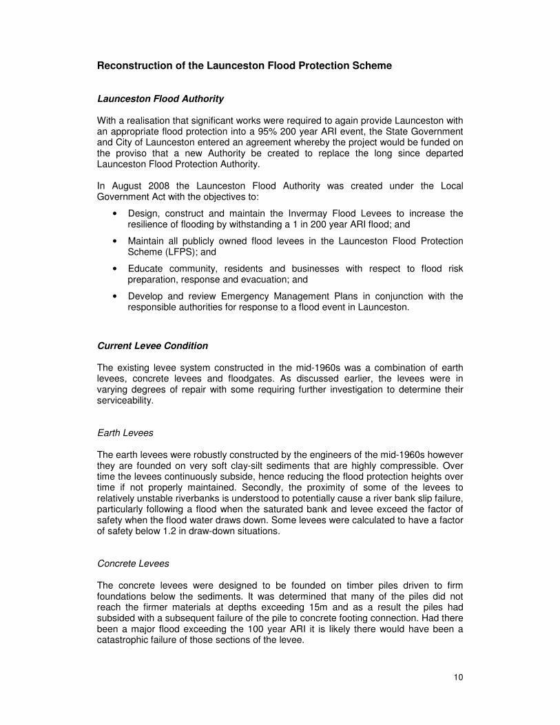
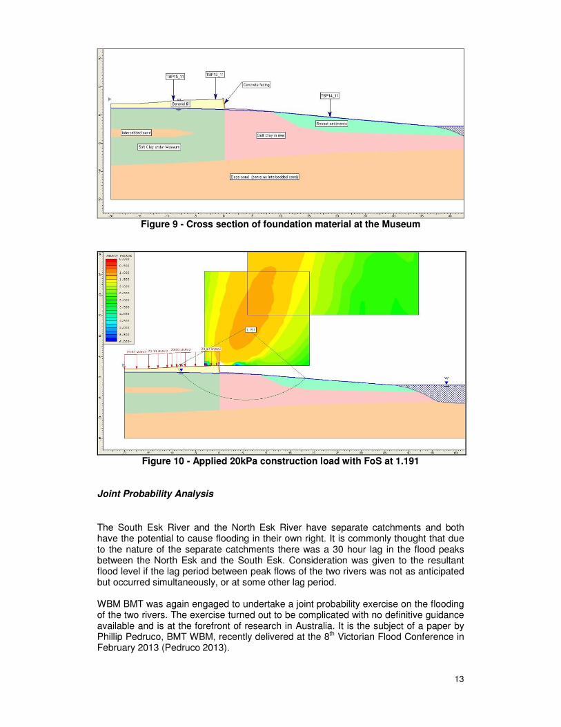
(Pitt&Sherry Dec 2011) The value of the foundation shear strength established over land was calculated at: Su = 13 + 1.3 z where z = depth in metres With the value of the foundation shear strength over water was calculated at: Su = 3 + 1.3 z where z = depth in metres River bank stability In addition to soil strengths, river bank stability was also a critical factor of the levee design. With the historic knowledge of the 1965 river bank failure, placing a heavy load such as an earth levee in close proximity to the river was expected to result in a bank failure. Analysis was carried out to determine if the existing levee presented this situation and also if the proposed levees were stable. The existing conditions at the location of the 1965 slip were assessed to be the most critical. Without any additional load the river bank was calculated to have a Factor of Safety (FoS) of only 1.64 (Pitt&Sherry Dec 2011), however when a construction surcharge was applied the FoS dropped to only 1.19. (Figure 9 & 10) The design implications were that any levee in this location had to bear directly on the firm material underlying the sediments and that loads applied during construction could not exceed 20 kPa or 200kg per square metre, making reconstruction almost impossible without specific consideration of load distribution.
13
Figure 9 - Cross section of foundation material at the Museum
Figure 10 - Applied 20kPa construction load with FoS at 1.191
Joint Probability Analysis
The South Esk River and the North Esk River have separate catchments and both have the potential to cause flooding in their own right. It is commonly thought that due to the nature of the separate catchments there was a 30 hour lag in the flood peaks between the North Esk and the South Esk. Consideration was given to the resultant flood level if the lag period between peak flows of the two rivers was not as anticipated but occurred simultaneously, or at some other lag period. WBM BMT was again engaged to undertake a joint probability exercise on the flooding of the two rivers. The exercise turned out to be complicated with no definitive guidance available and is at the forefront of research in Australia. It is the subject of a paper by Phillip Pedruco, BMT WBM, recently delivered at the 8th Victorian Flood Conference in February 2013 (Pedruco 2013).

14
From the Authority's perspective, the study determined that a coincidental 200 year ARI flood on both rivers would overtop the levee design height. The matter then became an issue of probability of how often this would occur and what was the cost benefit of designing for this very remote possibility. It was decided that because the probability of coincidental peak flows exceeded the 0.5% AEP (200 year ARI) it was beyond the responsibility of the Launceston Flood Authority to design for this occurrence. It was however deemed necessary for the emergency response agencies to be aware of the coincidental flood implications for evacuation purposes. Earth Levees Earth levees were selected in areas where river bank stability would allow their construction. Earth levees are considerably cheaper than reinforced concrete structures being constructed entirely from selected clays. Earth levees were designed with batters ranging from 1:2 to 1:4 depending upon the location, serviceability standard and public use. They are generally covered with lawned topsoil and in high flow locations rock beaching or geofabric protection was selected and applied prior to being topsoiled. The 'standard' levee was designed (Figure 11) with a two metre deep key into the founding materials to prevent underflow failure, although the width of the levee in most cases was sufficient to achieve this objective. A river-side berm was also considered as an aid to increasing the FoS. Natural ground level ranged between 1.5m AHD to 3.1m AHD requiring the levee height to vary between 2.0m to 3.5m above ground level dependent upon the flood level gradient contour.
Figure 11 - Typical earth levee cross section
Concrete Levees Concrete levees were selected where the river banks could not support the mass of an earth levee or where there was insufficient space for an earth levee. Concrete levees were also used to transition from an earth levee to an existing structure such as a bridge abutment. Design parameters for the concrete levees were to meet the following criteria:
- Design life of 80 years for all structural components
15
- 95% 200 year ARI flood heights were provided along the full length of the levees.
- Although the flood height varies along the wall, a constant wall height was given. Top of wall throughout is AHD 5.2m allowing for 600mm freeboard over the highest 95% 200 year ARI flood height.
- The structure was designed for flood water to the top of the wall including the freeboard height i.e 5.2m AHD
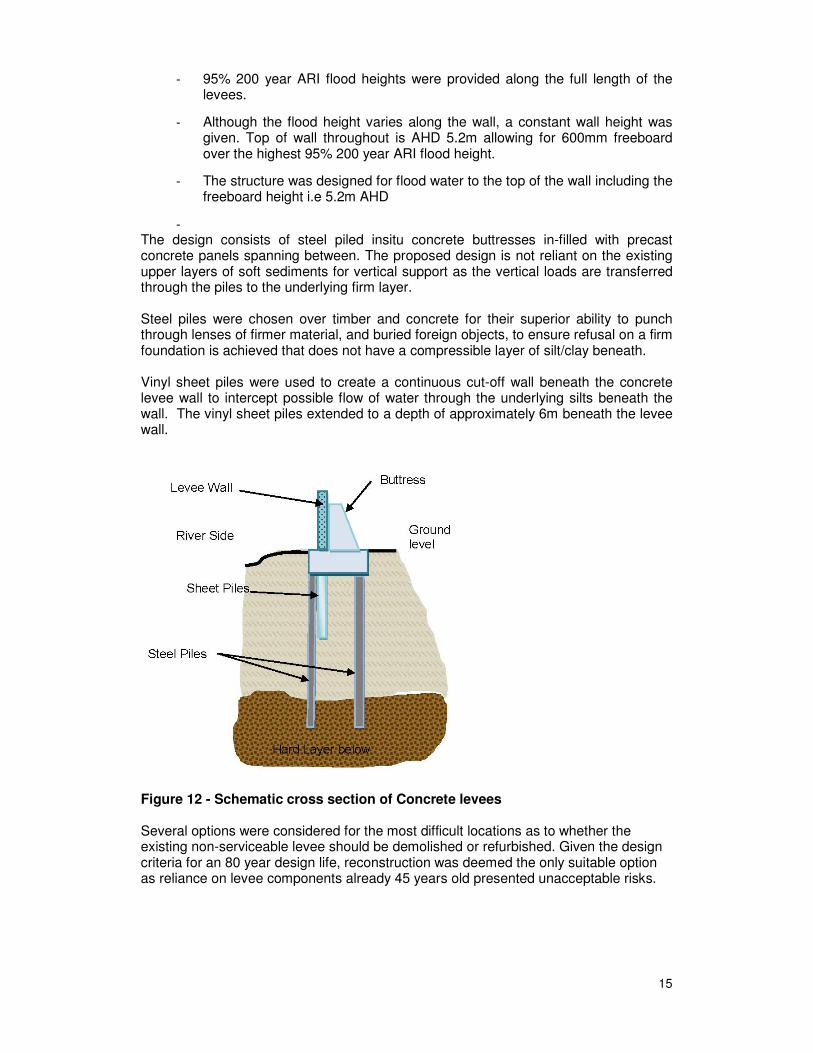
- The design consists of steel piled insitu concrete buttresses in-filled with precast concrete panels spanning between. The proposed design is not reliant on the existing upper layers of soft sediments for vertical support as the vertical loads are transferred through the piles to the underlying firm layer. Steel piles were chosen over timber and concrete for their superior ability to punch through lenses of firmer material, and buried foreign objects, to ensure refusal on a firm foundation is achieved that does not have a compressible layer of silt/clay beneath. Vinyl sheet piles were used to create a continuous cut-off wall beneath the concrete levee wall to intercept possible flow of water through the underlying silts beneath the wall. The vinyl sheet piles extended to a depth of approximately 6m beneath the levee wall.
Figure 12 - Schematic cross section of Concrete levees
Several options were considered for the most difficult locations as to whether the existing non-serviceable levee should be demolished or refurbished. Given the design criteria for an 80 year design life, reconstruction was deemed the only suitable option as reliance on levee components already 45 years old presented unacceptable risks.
16
Flood Gates Two types of flood gates were chosen for the Flood Protection Scheme being steel sliding gates and a demountable proprietary system by "Bauer". Steel gates were designed where it was practicable to have the sliding panel and the demountable system was used for structures such as bridges where space was limited. Another advantage of the demountable system was that the majority of the bays could be erected leaving the final bay open for essential service vehicles or community evacuations only installing the 'planks' as the waters rise. Legislative Framework In Tasmania, levees are considered a dam structure with oversight and permits being issued by the Tasmanian Assessment Committee for Dam Construction (ACDC) under the Water Management Act 1999, Section 157. Due to the substantial consequences of failure the proposed levees were in category High A. The final design for the levee required submission and application for a permit to construct. A permit was issued on 15 December 2009. Levee Reconstruction Levee reconstruction commenced in 2009 with the construction of three sliding floodgates at Forster, Lindsay and Taroona Streets (see Figure 13). Design of the gates was undertaken by GHD where the structures were founded on steel piles with tension cables drill into the underlying rock to prevent overturning. A system of sheet piles provided a junction to the adjoining earth levees. Once the gates were completed reconstruction of new earth levees commenced along Lindsay Street, replacing existing concrete and earth levees deemed to be unsalvageable or else constructed too close to the river bank to enable rectification without causing stability issues. These levees required compulsory acquisition of 17 commercial properties: an issue unto itself with massive unplanned financial implications for the project. Nonetheless, the properties were acquired and the levees were constructed to the extent possible awaiting resolution of one acquisition. Investigations of the existing earth levee adjacent to the Tamar River indicated the levee only required re-facing with new clay material. This work commenced in 2011 and is now complete. In 2012 construction commenced on the final components, being the concrete levee sections. These, as discussed earlier, are used for transitions between earth levees and bridge abutments and where space or river bank stability issues did not allow for earth levee construction.

17
Figure 13 - Works status as at 31 March 2013

18
Summary At the time of writing this report, the Launceston Flood Management Project is now in its final stages of reconstruction with completion scheduled for December 2013. The project is considered to be a resounding success thus far but has not been without its issues. Probably the single biggest issue was that of cost control, particularly around the matter of the compulsory land acquisitions which are subject to the Tasmanian Land Acquisition Act 1993. The Act had to be amended to allow this project to proceed. The Act allows several methods of compensation to be established which can be nominated by the land owner, each method having differing financial implications for the project; a very difficult budgeting issue. The next largest issue that arose was the greater than anticipated subsidence of the earth levees. Consulting engineers estimated the initial settlement in the first 12 months was going to be approximately 300mm. This figure was reached after only 6 months and as at today the levees in Lindsay Street have settled over double that. Concerns were raised that the excessive settlement may have caused a river bank slip failure. Fortunately inclinometers were installed prior to construction allowing accurate monitoring of the sub soil pressures. The settlement rate is now reducing as has been recalculated providing some comfort to the designers. Miscalculation of the allowable soil pore pressure was the given cause of the miscalculation. To date $43M has been expended from an expenditure budget of $57M. Considerable savings have been achieved through design reviews whereby the projected expenses have been reduced from $71M to currently $54M. Upon completion of the reconstruction project the Flood Authority will move into the maintenance phase of topping up the recently constructed levees and concentrate on improvements to the levees on the CBD side of the system. References:
BMT WBM (2008) "River Tamar & North Esk River Flood Study Final Report", Report
no. R.M7246.002.01 November 2008
BMT WBM (2009) "Hydrodynamic Modelling of the Tamar Estuary - Final Report" -
Report no. R.B15279.007.02
Cox C.J. (2003) "Review of the Flood Hydrology for Trevallyn Dam", Hydro Tasmania
Report No. 111557-report 5, 12 September 2003
Foster D.N., Nittim R. and Walker J. (1986) "Tamar River Siltation Study". WRL
Technical Report no. 85/07, October 1986
HEC (1992) "Design flood for Launceston flood protection review", report prepared by
the Hydro-electric Commission for Launceston City Council
Hyrdo Tasmania Consulting (2008), "Trevallyn Flood Frequency Review for
Launceston City Council" - August 2008

19
Munro C.H. (1959) "Report on Flood Mitigation measures for the City of Launceston" -
Volumes I and II, September 1959
Pitt&Sherry (Oct 2011) "Scottsdale Levee Specialist Geotechnical Testing Interpretive Report Contract CD17/2011", October 2011 WRL (2006), "North Esk Flood Frequency Analysis at Corra Linn", Report prepared for Launceston City Council, Technical Report No.2004/16 January 2006 Pedruco (2013), "Using Joint Probability Methods to Quantify the Joint Dependence of Extreme Events on the North and South Esk Rivers", February 2013.