layout and modeling of a high temperature heat storage...
TRANSCRIPT

UNIVERSIDADE DE LISBOA
FACULDADE DE CIEcircNCIAS
DEPARTAMENTO DE ENGENHARIA GEOGRAacuteFICA GEOFIacuteSICA E ENERGIA
Layout and modeling of a high temperature heat
storage system for continuous operation of solar
reforming processes
Pedro Miguel Boim Esteves Alves Roda
Dissertaccedilatildeo
Mestrado Integrado em Engenharia da Energia e do Ambiente
2014
UNIVERSIDADE DE LISBOA
FACULDADE DE CIEcircNCIAS
DEPARTAMENTO DE ENGENHARIA GEOGRAacuteFICA GEOFIacuteSICA E ENERGIA
Layout and modeling of a high temperature heat
storage system for continuous operation of solar
reforming processes
Pedro Miguel Boim Esteves Alves Roda
Dissertaccedilatildeo de Mestrado em Engenharia da Energia e do Ambiente
Trabalho realizado sob a supervisatildeo de
Henrik von Storch (DLR)
Professor Guilherme Carrilho da Graccedila (FCUL)
2014
Acknowledgements
I would like to thank my supervisor Prof Guilherme Carrilho da Graccedila and my co-supervisor Henrik
von Storch all the support that they gave along my work
In particularly I would like to thank to Henrik von Storch for the entire time spent helping teaching
and guiding me on my thesis
I also would like to thank to DLR (German aerospace center) to provide all the resources needed to my
work and to thank to DLRrsquos collaborators to receive me as one of them Also my thanks to the
Sciencersquos Faculty from the Univesity of Lisbon for giving me the chance to study abroad and fulfill
my expectations as a student
Also would like to thank my parents and siblings that helped trough all my academic life and made
possible for me to achieve this moment
Also my most sincerely thanks to all my friends in particular Leonardo Roda Gonccedilalo Nunes and
Maacuterio Silva that always gave me the best advises and made me be a better person
And at last but not least the most important thanks to my girlfriend Ana Tostatildeo that helped me and
dealt with me for my whole academic life without giving up
Abstract
This thesis comprises a model of a high temperature heat storage system modelled in Aspen Custom
Modelerreg to be implemented in a solar methane reforming plant model The model is a 1D
approximation and does not consider thermal losses The pressure drop along the system is considered
as well as the temperature dependency of the fluid properties The system modeled is a sensible heat
storage system and uses alumina ceramic honeycombs as storage material
The implementation of the storage system in a solar methane reforming plant will make possible to
reduce the size of the plant increase the operating period of the plant and achieve a constant annual
output of the plant
The thesis also presents a short state of the art in heat storage systems The main objective of the thesis
is to model the heat storage system to be implemented in a continuous operation simulation and also
determine a relation between the layout of the system and the operating time of the plant
Resumo
Esta tese conteacutem um modelo de um sistema de armazenamento teacutermico de alta temperatura o software
usado para criar o modelo foi Aspen Custom Modelerreg que seraacute implementado num modelo de uma
central de reformaccedilatildeo solar de metano O modelo eacute uma aproximaccedilatildeo unidimensional e as perdas
teacutermicas satildeo desprezadas A variaccedilatildeo da pressatildeo e as propriedades dependentes da temperatura satildeo
consideradas neste modelo O sistema modelado eacute um sistema capaz de armazenar calor sob a forma
de calor sensiacutevel usando ceracircmica alumina como material armazenador
A implementaccedilatildeo deste sistema numa central de reformaccedilatildeo solar de metano iraacute permitir a reduccedilatildeo do
tamanho da central permite aumentar as horas em operaccedilatildeo ao longo do ano e permite que a central
opere com um output constante durante todo o periacuteodo em operaccedilatildeo
Esta tese apresenta ainda um pequeno estudo do estado da tecnologia em sistema de armazenamento
teacutermico O principal objectivo da tese eacute a criaccedilatildeo do modelo do sistema de armazenamento teacutermico em
que permita a operaccedilatildeo contiacutenua durante a sua simulaccedilatildeo Eacute tambeacutem objectivo deste trabalho
apresentar uma relaccedilatildeo entre o dimensionamento do sistema (material necessaacuterio) e o periacuteodo que a
central opera
Palavras-chave Heat storage High temperature storage modeling solar reforming with storage
Index
Abstract v
Resumo v
1 Introduction 1
11 Concentrating solar principles 1
111 Concentrating solar technologies 2
112 CSP projects in Portugal 3
12 Environmental Profile 4
13 Socio-Economic impacts 5
14 Reforming process 6
141 Hydrogen production and methane reforming 6
2 Thermal storage 7
21 Thermal energy storage concepts 7
211 Active direct and indirect storage systems 7
212 Passive storage systems 7
22 Storage Media 8
221 Sensible Heat Storage 8
222 Latent heat storage 11
223 Thermochemical heat storage 16
3 Mathematical model 19
31 Introduction 19
311 Storage structure 20
311 Storage system general properties 20
311 Honeycomb storage principle 21
32 Physical model 21
33 Governing Equations 22
331 Boundary and initial conditions 23
331 Pressure drop 24
331 Energy balance 24
34 Model Validation 24
341 Comparison with experimental data 24
341 Comparison with previous validated models 25
341 Comparison with a Comsol Multiphysicsreg model 26
341 Comparison between Aspen Models 27
35 Validation discussion 28
4 System sizing 28
41 Introduction 28
42 Mass flow variation 29
43 Energy available 29
44 Operating hours 30
45 System volume and shape 30
46 System design 30
461 Reference case 31
462 Charged and discharged gradients regarding extra length 31
47 Reference case results 33
5 Conclusions 33
6 References 34
Appendix A - Aspen Custom Modeler Model Code 38
Appendix B - Hourly intercept radiation and correspondent air mass flow 40
List of Figures
Fig 1 - Technologies for concentrating solar radiation (Agrafiotis von Storch et al 2014) 3
Fig 2 - Hybrid unit layout to be built in Tavira by the SOLMASS project (Coelho Domingues et al
2010) 4
Fig 3 - Scheme of active direct (left) and active indirect (right) storage systems 7
Fig 4 - Scheme of a passive storage system 8
Fig 5 - Steam accumulator scheme (Laing 2008) 11
Fig 6- Schematic of the sandwich concept using graphite foil (Steinmann and Tamme 2008) 14
Fig 7 - Example of a cascaded latent heat storage system (Michels and Pitz-Paal 2007) 15
Fig 8 - 3D representation of the concept (Verdier Ferriegravere et al 2014) 15
Fig 9 - Evolution of the PCM temperature during heating (left) and cooling (right) phase (Verdier
Ferriegravere et al 2014) 16
Fig 10 - Comparison of thermochemical redox behavior of cobalt oxide in powder and pellet form
(Karagiannakis Pagkoura et al 2014) 18
Fig 11 - Honeycomb brick 20
Fig 12 - Physical model of the storage system 21
Fig 13 - Representative thermal gradient in the storage system 22
Fig 14-Initial gradient comparison between aspen model and (Hirsch IRT et al 2012) model
Horizontal axis is normalized 25
Fig 15 - After one hour charging gradient comparison between Aspen model and (Hirsch IRT et al
2012) model Horizontal axis is normalized 26
Fig 16 - Comsol results after one hour simulation 27
Fig 17 - Comparison with comsol model 27
Fig 18 - Comparison between the two different Aspen models 28
Fig 19 - Solar methane reforming plant with storage scheme 29
Fig 20 - Relation between operating hours of the plant and storage material volume needed Vertical
axis is normalised 31
Fig 21 - Reference case discharged temperature gradient considering extra length 32
Fig 22 - Reference case charged system temperature gradient considering extra length 33
List of Tables
Table 1- Land use comparison between energy conversion technologies (European Academies Science
Advisory Council 2011) 5
Table 2- Illustrative costs of generating technologies in 2010 (currency conversion 2010 $euro = 0755)
(European Academies Science Advisory Council 2011) 6
Table 3 - Material characteristics 11
Table 4 - Melting temperature for different compounds 13
Table 5 - Storage specifications 20
Table 6-Alumina porcelain (C130) properties 20
Table 7 - Reference case parameters 31
Table 8 - System final dimensions 32
Table 9 - Simulations results for the first 8 hours of the whole year 33
Nomenclature Description Units
Nu Nusselt number
Re Reynolds number
Pr Prandtl number
S Air channel opening M
L Air channel length M
nair Air flow Kmols-1
cpair Air heat capacity kJ(kmol-1K-1)
Tair Air temperature degC
λair Air conductivity W(m-1K-1)
ρair Air density kmolm-3
Acsair Air channel cross section m2
ℎ119886119894119903 Air enthalpy kJkmol-1
λsol Ceramic conductivity W(m-1K-1)
ρsol Ceramic density kgm-3
Cpsol Ceramic heat capacity kJ(kg-1K-1)
Acssol Ceramic cross section m2
Tsol Ceramic Temperature degC
α Convection heat transfer coefficient between air and ceramic W(m-2K-1)
119876119904119905119908119886119897119897 Energy stored in the solid kJ
119876119886119894119903 Enthalpy air variation kJ
119905119900119904119905119900119903119886119892119890 Energy available to store kJh-1
119876119878119905119900119903119886119892119890(119905 + Δ119905) Energy stored kJ
∆119901 Pressure drop bar
119891 Friction factor
119863 Hydraulic diameter m
Vair Air velocity ms-1
Ti Initial temperature K
Tm Melting temperature K
m Mass of heat storage medium Kg
am Fraction melted
mh Heat of fusion per unit mass Jkg-1
Abbreviations
CSP Concentrating Solar thermal Power
HTF Heat transfer Fluid
LEC Levelised Electricity cost
EPC Engineering procurement and construction
OampM Operation and maintenance
SMR Steam methane reforming
DMR Dry methane reforming
STJ Solar Tower Juumllich
Layout and modeling of a high temperature heat storage system
Pedro Miguel Roda 1
1 Introduction It is a fact that the fossil fuels resources are limited around the world Due to that limitation and also
their harmful contribute to the humanity and climate greatly because of their CO2 emissions the is
experiencing an increasing usage of renewable energy sources (Muumlller-Steinhagen and Trieb 2004)
Governments and companies all over the world are turning their own mind-set to a more sustainable
future with incentives to reduce their foot print and the so called ldquogreen economyrdquo
A transition between a fossil fuel based mature and well known grid to a renewable based grid cannot
be an abrupt process When renewable energy resources are added to the grid they bring with them
instability and fluctuation which reduces the feasibility and quality of the grid There are already a
couple of renewable energy technologies in a higher level of maturation like PV and wind power
which enables them to be the renewable energy technologies with most installed capacity worldwide
(Trieb Fichter et al 2014) Even with PV and wind power with already being integrated in the grid
there is still a problem of transportation because usually the high sun rich (or wind rich) regions are
not necessarily the regions with high energy demand
A lot of researchers and research centres are putting their effort on studying concentrating solar
technologies in order to integrate this technology in the grid in a near future like any other renewable
energy source concentrating solar plants are instable and also like other solar technologies it is
intermittent This intermittency represents the biggest challenge to this technology although there is a
possibility to integrate a thermal storage system to these solar plants which could increase the working
hours of these solar plants and also could make this technology more versatile and make use of the
energy produced in periods with a higher energy demand (Nagl Fuumlrsch et al 2011)
Concentrating solar plants are also being studied by researchers that believe that it can be a solution
for the transportation drawback Their investigations show that these plants could be used as an heat
source for a gas reforming process which would produce fuels with an high heat capacity and lower
CO2 emissions when in combustion these fuels are usually called solar fuels (Storch Roeb et al
2014) Solar energy will become a competitive technology as soon as this challenges are overcome
(Yang Du et al 2013)
This thesis gives a short introduction to concentrating solar plants and technologies a state of the art in
thermal storage systems and an introduction to the solar methane reforming process
The objective of the thesis is to create model a thermal storage system to be implemented in a model
of a solar methane reforming plant for continuous operation and also determine the relation between
storage material needed and working hours of the plant
11 Concentrating solar principles
The most common way for producing electricity is to make use of a watersteam cycle On a
traditional fossil fuelled plant the fuel is combusted the heat produced is used to boil water and
produce steam that will spin a turbine and generate electricity In concentrating solar plants (CSP) the
high temperature heat will be achieved with solar radiation Solar radiation collectors usually mirrors
redirect and concentrate the solar radiation into a point or line depending on the technology This
radiation focused in the heat exchanger will increase its temperature Then a heat transfer fluid (HTF)
will flow along the heat exchanger and will be used to heat up water produce steam and generate
electricity as in a conventional fossil fuelled plant (Pitz‐Paal Buck et al 2013)
Unlike PV that can make use of diffuse solar radiation CSP can only make use of direct solar
radiation Two different principles based on mirrorrsquos shape are distinguished parabolic principle and
Fresnel principle (Vogel and Kalb (April 2010)
Layout and modeling of a high temperature heat storage system
Pedro Miguel Roda 2
111 Concentrating solar technologies
CSP makes use of lenses or mirrors to concentrate direct solar radiation into a point or line Depending
on technology the concentration factors can be from 50 to thousands (Pitz‐Paal Buck et al 2013) The
technologies differ in configuration mirrorrsquos size and shape and application
bull Dish plants
This technology makes use of a paraboloid dish mirror to reach the highest concentration
factors in the range of 1000 - 3000 Due to the tracking system of this technology the
incident solar radiation in the dish is all redirected to the heat engine or receiver located in
a higher central point On bottom right of Fig 1 can be seen a representative scheme of
this technology
bull Tower power plants
Large mirrors are distributed along a field and for an array the mirrors are individually
monitored and track the sun with the aid of a double axis tracking system and focus the
solar radiation into a point on the top of the tower In this technology the temperatures
achieved in the receiver are from 600degC to 1200 degC (Vogel and Kalb April 2010) On top
right of Fig 1 can be seen a representative scheme of this technology
bull Parabolic Trough
The mirrors are usually called ldquoU-shapedrdquo When assembled the parabolic trough plants
look like a cylinder cut in a half with a smaller tube in the center This smaller tube is the
receiver of this technology where the sunlight is focused Due to the redirected radiation
the tube is heated up and consequently heats up the HTF that is flowing inside The
maximum operation temperature reached until now is around 550degC and some researchers
are investigating the production of steam directly inside the tube (Vogel and Kalb April
2010) On top left of Fig 1 can be seen a representative scheme of this technology
bull Linear Fresnel plants
The mirrors are nearly planar and placed closed to the ground The mirrors are distributed
parallel to each other forming a line and focusing the solar radiation into a receiver that is
facing the ground The mirrors track the sun with the aid of a single axis tracking system
(Vogel and Kalb April 2010) On bottom left of Fig 1 can be seen a representative scheme
of this technology
Layout and modeling of a high temperature heat storage system
Pedro Miguel Roda 3
Fig 1 - Technologies for concentrating solar radiation (Agrafiotis von Storch et al 2014)
112 CSP projects in Portugal
Portugal has a great potential to explore this type of technology In this chapter are shown two CSP
projects in Portugal
bull SOLMASS project
This project will build a 4MW solar tower power plant using a central receiver system
The plant will be constructed in Tavira Algarve as development platform (Coelho
Domingues et al 2010) This will be a hybrid unit and will use Biomass as backup A
layout of the hybrid unit can be seen in Fig 2
Layout and modeling of a high temperature heat storage system
Pedro Miguel Roda 4
Fig 2 - Hybrid unit layout to be built in Tavira by the SOLMASS project (Coelho Domingues et al
2010)
bull Parabolic salt loop project
The plant is of parabolic trough type and is already under construction in Eacutevora Portugal
The aim of the project is demonstrate the viability of this system using molten salt as
alternative heat transfer fluid (Muumlller-Elvers Wittmann et al 2012)
12 Environmental Profile
It is mandatory to assess the environmental impacts of CSP and even if they are less when compared
with conventional fossil fuelled technologies they cannot be neglected It is a fact that CSP greenhouse
gas emissions are lower than when compared with the same conventional plants although the CSP
impacts are local and can directly affected its surroundings Some of them such as water issues land
use energy and materials use and emissions will be reviewed in the following points
bull Water issues
In CSP water is used for cooling purposes Also the places rich in sun and water usually
are the most populated which means that a rational usage of water should be made An
alternative to water is to use air as cooling medium but it will affect the efficiency of the
process
Water in CSP is also used to keep the mirror cleaned and keep their reflective properties
although the amount of water used for cleaning purposes is much lower when compared
with amount used for coolingrect sunlight and hence are best constructed in arid or semi-
arid regions globally known as the Sun Belt
CSP are often designed to use water for cooling at the back-end of the thermal cycle
typically in a wet cooling tower A typical 50MW parabolic trough plants uses 04 ndash 05
million m3 of water per year for cooling (European Academies Science Advisory Council
2011) Vogel and Kalb (April 2010) also show that the dry cooling system increases the
Layout and modeling of a high temperature heat storage system
Pedro Miguel Roda 5
investment costs due to specific operating and maintenance costs of the system the Solar
Tower Juumllich (STJ) is an example of a facility using this system
bull Land use
Land use is the total area occupied by all the structures that belong and are needed to keep
the plant working In a CSP technology the collectors field is the structure that will
require a bigger area usually CSP are built in arid places that will have clear skies And
like any other energy technology it will also bring some visual effects on the nearer
populations even when CSP one technology that makes a relatively efficient usage of the
land occupied when compared to other solar technologies (Tsoutsos Frantzeskaki et al
2005) Table 1 shows a comparison between energy conversion technologies and CSP It
is presented in relation to the energy generated annually by each plant (European
Academies Science Advisory Council 2011)
Table 1- Land use comparison between energy conversion technologies (European Academies Science Advisory Council 2011)
Land use [m2(MWh-1 y-1)]
Parabolic solar power Spain 11
Solar tower power Spain 17
Photovoltaic power plant Germany 56 (photovoltaic power can also be placed on rooftops which
corresponds zero land use)
Wind power lt5
Biomass plantation France 550
Open-cast mining (lignite) Germany 60
High-voltage power transmission line across Europe 04
bull Energy and materials use
If a life cycle assessment is made of a CSP technology it is immediately noticed that the
greenhouse gas emissions are much lower than in conventional fossil fuelled power plants
although there are still some emission associated with CSP Most of these emissions are
related to the really high material use of CSP such as steel pipes and mirrors and if
storage is implemented the salts used as storage system
CSP greenhouse effects can increase if fuel backup is used because this is the only
situation that fuel is used in CSP technology (European Academies Science Advisory
Council 2011) and excepting these cases no fuel is used in CSP plants
13 Socio-Economic impacts
As it is mentioned before the impacts of CSP are mostly local this is also true for socio economic
impacts CSP technology needs some employees with high know-how but also need cleaning teams
and maintenance so the local market can benefit with the project Also the construction materials
since they are ordinary construction materials such as steel or concrete can be purchased in local
providers A lot of CSP projects are built in smaller towns or isolated places the local population can
benefit of an increase demand of ordinary goods and services
CSP costs vary with technology but the solar fieldrsquos costs represent the biggest cost of the project
There will be operation and maintenance costs and also costs with personnel It is extremely difficult
to make a comparison between conventional fossil fuelled power plants and renewable energy power
plants A usual methodology to compare costs of electricity generation between such technologies is to
calculate the ldquolevelised electricity costrdquo (LEC) which relates average annual capital and operating
costs of the plant to the annual electricity production (European Academies Science Advisory Council
2011) Table 2 illustrates the costs of generating technologies in 2010 (European Academies Science
Advisory Council 2011)
Layout and modeling of a high temperature heat storage system
Pedro Miguel Roda 6
Table 2- Illustrative costs of generating technologies in 2010 (currency conversion 2010 $euro = 0755) (European Academies Science Advisory Council 2011)
Technology LEC
[eurockWhe-1]
Capacity
[MW]
EPC cost
[eurokWe-1] Cap factor
Fuel costs
[eurockWhe-1]
OampMfix
[eurokW-1 y-1]
OampMvar
[eurockWhe-1]
CSP 100 MW
no storage
(Arizona)
179 100 3542 028 0 48 0
Pulverised coal
650MW base-
load
69 650 2391 090 29 27 03
Pulverised coal
650MW base-
load
90 650 2391 057 29 27 03
Gas combined
cycle mid-load 61 540 738 040 32 11 03
Wind on-shore
100MW 85 100 1841 03 0 21 0
Wind off-shore
400MW 153 400 4511 04 0 40 0
Photovoltaic
150MW
(Arizona)
212 150 3590 022 0 13 0
Analysing Table 2 it is easy to notice that there is a long way for renewable energy resources to
become competitive in the energy market Although with so many incentives and with the aim of
governments to turn fossil fuelled economies into clean energy economies And with the aim of
private investors to reduce their companies carbon foot print it is expected that a cost reduction by
scaling up renewable energy projects and technology innovations will turn renewable energy
resources into a competitive option (European Academies Science Advisory Council 2011)
14 Reforming process
141 Hydrogen production and methane reforming
Hydrogen production it is a process that is already being studied for a long time Hydrogen production
is mostly made by converting a material with high contents of hydrogen (H2) such as gasoline
ammonia or methanol into hydrogen rich flow This hydrogen can be later used in recent
technologies like fuel cells s an energy carrier and as an important ldquoraw materialrdquo in chemical
industries and refineries
Theoretically the hydrogen produced all around the world nowadays is produced by the catalytic
reforming of methane technique Different reactions can take place in methane reforming and two of
them are (1) steam methane reforming (SMR) and (2) CO2 (or dry) methane reforming (DMR)
(Agrafiotis von Storch et al 2014)
molkJHOHCH 206 CO3H 224 (1)
molkJHCOCH 247 CO22H 224 (2)
Both reactions are endothermic which means that an heat source is needed so that the reactions can
take place (Agrafiotis Von Storch et al 2014) Currently the hydrogen produced from fossil fuels is
used as a chemical in industrial processes
The reforming process as mentioned above needs energy to occur If solar energy (or any other
renewable energy resource) is used the process becomes free of fossil fuels and in this case the
production of solar fuels is achieved The process takes place in a range of temperatures from 800 to
1000degC which also means that there are already CSP technologies that can fit in this range
Layout and modeling of a high temperature heat storage system
Pedro Miguel Roda 7
2 Thermal storage Independently of the energy production technology it is a great advantage if the energy is coming from
a versatile dispatchable technology This property enables the technology to provide energy (almost)
on demand It is a fact that solar is a non-dispatchable technology and this represents one of the major
challenges on solar technology
In CSP there is the option to integrate a thermal heat storage system that could maintain the plant
working during cloudy periods and if the thermal storage capacity is big enough during night periods
Currently a lot of the researchers effort is to improve this systems and find one that is feasible and do
not compromise the efficiency of the process and do not increase the cost of the whole plant into
extremely high values
This chapter gives an overview on the different types of thermal storage concepts classification and
materials and their properties
21 Thermal energy storage concepts
There are different concepts for thermal heat storage systems Two groups can be identified active
and passive systems And active storage systems can be independently identified as direct or indirect
This type of classification is independent of the systemrsquos storage material and physical storage (Gil
Medrano et al 2010)
The decision on which type of technology will be used in a certain application depends on operation
temperature boundary conditions and development of the technology
211 Active direct and indirect storage systems
An active direct storage system is a more difficult system to implement because in this system the
storage material is also the heat transfer fluid which means that is necessary to find a material that can
be a good heat transfer fluid and a good storage material decreasing the options that can fit in both
An indirect storage system usually makes use of two different materials one is the heat transfer fluid
and other one is the storage material and by pumping the heat transfer fluid through a heat exchanger it
will heat up the storage material that is also being pumped Usually this is a more complex system in
terms of infrastructures because tanks are needed (Gil Medrano et al 2010) A scheme of these
concepts can be seen in Fig 3
Fig 3 - Scheme of active direct (left) and active indirect (right) storage systems
212 Passive storage systems
In a passive storage system the heat transfer fluid will be pumped through another medium that will be
the storage material in this system the storage material is not being pumped and the heat transfer fluid
is just used to charge or discharge the storage system (Gil Medrano et al 2010) A scheme of this
storage concept can be seen in Fig 4
Layout and modeling of a high temperature heat storage system
Pedro Miguel Roda 8
Fig 4 - Scheme of a passive storage system
The most common storage systems applied until now are the indirect storage system and the passive
systems (or regenerators) On the next section there will be a detailed description about the storage
medium and physical storage
22 Storage Media
The storage system can have different storage media such as liquid solid or gaseous the system can
also make use of different physical phenomena to store energy by heating up a medium without phase
change making use of a phase change of a material at a certain temperature or by chemical reactions
that are completely reversible
On the following sections a detailed description on each storage media and some of their applications
is presented
221 Sensible Heat Storage
Sensible heat storage means that the energy will be stored in a material without its phase change It is
important to make a wise choice of material as well as an intensive study of its behavior under
operating conditions The material can be liquid solid or gaseous and it will store energy accordingly
with (3) (Hasnain 1998)
∆11987612 = 119898 int 119888119901(119879)119889119879
1198792
1198791
(3)
2211 Sensible heat storage materials
As it is mentioned above the storage material choice is a crucial point in heat storage systems The
material has to have desired properties for the application And even when different physical heat
storage will be presented the storage materials will have a lot of properties in common A list of
desired properties of storage materials to be implemented in a sensible heat storage system are
Layout and modeling of a high temperature heat storage system
Pedro Miguel Roda 9
presented below and categorized in thermo-physical-(A) chemical-(B) mechanical-(C) economic-
(D) and environmental (E) properties (Khare DellAmico et al 2013)
(A)
bull High energy density
bull High thermal conductivity
bull High heat capacity
bull High density
bull Long thermal cycling stability
(B)
bull Long thermal chemical stability with no chemical decomposition
bull Non-toxic
bull Non-explosive
bull Low corrosion potential or reactivity to heat transfer fluids
bull Compatible with materials of construction
(C)
bull Good mechanical stability
bull Low coefficient of thermal expansion
bull High fracture toughness
bull High compressive strength
(D)
bull Cheap and abundant materials
bull Low cost of manufacturing into suitable shapes
(E)
bull Low manufacturing energy requirement
bull Low CO2 foot print
After evaluating the properties requirements for a certain application a short list of materials should be
elaborated and the materials should be intensively studied Find if the material deteriorates under
operating conditions feasibility and thermal behavior For high temperature applications the most
promising materials are ceramics and metals (Khare DellAmico et al 2013)
2212 Sensible heat storage concepts
The two main concepts of sensible heat storage systems are solid and liquids which will be explained
in detail on the following points
bull Solids
Chose a solid material as a storage the storage material is usually a choice based on its low
cost When solids are used ordinarily concrete leakages phase changes freezing or
evaporation problems are not faced On the other hand solids durability degradation after
several cycles of use and their low thermal conductivity represent the biggest
disadvantages of this concept (Shukla 1981)
Layout and modeling of a high temperature heat storage system
Pedro Miguel Roda 10
bull Liquids
Liquids have the high thermal conductivity as their big advantage but for high
temperatures they have to be pressurized Freezing and boiling points are the biggest
challenges on sensible heat storage systems using liquids as storage material which also
makes it a more difficult storage material to store (Shukla 1981)
There are already few systems implemented under investigation or in test campaigns On the
following sections some examples of both concepts are presented
2213 Examples of sensible heat storage systems
bull Concrete
Concrete is a tempting option since it is a relatively cheap material it is widely use around
the world and it is abundant
The systems using concrete as storage material consist of concrete block that is crossed by
a tube matrix The heat transfer fluid flows through the tubes and heats up the concrete
block This concept has already been tested and concrete showed a great durability
performance Although the system requires a huge area to be installed and its low thermal
conductivity has to be improved which represent the biggest disadvantages of the system
Thermal stability of concrete was evaluated but only for temperature ranges of 400 -
500degC For this temperature ranges a concrete storage test module was built and tested in
The system was tested in a temperature range between 400 - 500degC in Stuttgart
Germany (Laing Bahl et al 2012) A system sizing determination for the parabolic
through solar thermal power plant of the ANDASOL-type was calculated and a 50000 m3
is required and has to be built in a modular approach (Laing Bahl et al 2012)
Some solutions for the poor thermal performance due to concretersquos low thermal
conductivity (range 12 ndash 145 W m-1
K-1
) were investigated and an improvement of
around 15 was achieved by adding structures with high thermal conductivity (Laing
Steinmann et al 2008)
bull 2 Tank molten Salt Indirect Storage
The two tank system is one of the most storage systems implemented This system uses
liquid as the storage media This heat storage system consists of 2 tanks one hot tank and
one cold tank During charging the salt from the cold tank is pumped through the heat
exchanger and is heated up by the heat transfer fluid and stored in the hot tank During the
discharging cycle the direction is reversed and the hot salt heats up the heat transfer fluid
and is stored in the cold tank If the heat transfer fluid is also used as storage material the
heat exchanger is not needed in the systems
This is system was successfully tested in the Solar Two project and its operating
temperatures are between 290-390degC using a molten salt mixture This system is always
limited by the molten salt allowable operating temperatures because the mixture cannot
freeze inside the tanks or pipes system it limits the lowest temperature And since
corrosivity increases with the temperature for molten salts tankrsquos materials have to be
chosen carefully And the mixturersquos thermal performance can be affected in higher
temperatures (Kolb 2011 Dunn Hearps et al 2012)
bull Steam accumulator
Steam accumulators systems are storage systems for short periods that solar radiation is
not available like cloudy periods since accumulators deliver the energy stored quickly
and its cost are proportional to the pressure vessel used in the system
Steam accumulators make use of the high water thermal conductivity property and since
water is not liquid above 100degC for CSP applications it has to be pressurized The system
Layout and modeling of a high temperature heat storage system
Pedro Miguel Roda 11
is charged by providing steam to the liquid medium of the steam accumulator that will
increase the liquid water temperature For discharging the pressure is lowered and steam
is generated A scheme of this system is presented in Fig 5
Fig 5 - Steam accumulator scheme (Laing 2008)
bull Packed bed (and regenerators)
In a packed bed system the heat transfer fluid flows through a container that is full with
small particles made of materials with high thermal conductivity Regenerators are
structures with high thermal conductivity and the heat transfer fluid flows through them
The regenerator concepts is a known system from the aluminum industry that is carried
out at temperatures around 1100degC usually using ceramics materials
This type of system is implemented in the STJ in Juumllich where is used as heat transfer
fluid and alumina is the storage material and its properties are shown in Table 3 The
storage and heat transfer fluid are in direct contact during chargingdischarging process
The air flows through small channels this structure is typically called honeycomb brick
(Zunft Haumlnel et al 2011) The system has already been tested under operating conditions
between asymp200- 630degC (in March 2010) and it has a good thermal performance delivering
air almost at constant temperature when discharging (Zunft Haumlnel et al 2011)
A pebble bed regenerator was investigated by Fraunhofer UMSICHT making use of
extremely small spherical materials (3 to 12 mm diameter) if alumina oxide pebbles are
used the system can reach high temperatures since the maximum operating temperature
for this material is 1800degC (Daschner Binder et al 2013)
Table 3 - Material characteristics
Honeycombs
Material Alumina porcelain (C130)
Specific heat capacity 088 kJ(kgK)
Thermal conductivity 21 W(mK)
222 Latent heat storage
Latent heat storage systems make use of the release of heat during a phase change of a material This
concept has the advantage that it can occur almost at a constant temperature The process should be
reversible so the material will not change its properties after several cycles It is also mandatory that
all the material can be converted to the previous phase completely (Hasnain 1998) In this system it is
even more crucial an accurate choose of material that can fit to the specific application
Layout and modeling of a high temperature heat storage system
Pedro Miguel Roda 12
2221 Material to be used as PCM
It is expectable that the most investigated phase transition would be the transitions that release more
energy although the early investigations began with the phase change solid-liquid that usually releases
less energy than the liquid-vapor transitions This is explained that a better container is needed and
also leaking problems are more likely to happen when leading with gases (Abhat 1983)
As it is mentioned above the material should match the specific operating temperature range almost
perfectly The properties of the material even that they are similar to the properties of the materials
used for sensible heat they should have some specific performance due to their phase change usage
The thermodynamic (A) kinetic (B) chemical (C) and economic (D) criteria used to evaluate PCM
materials are (Abhat 1983)
The phase change material (PCM) should possess
(A)
bull A melting point in the desired operating temperature range
bull High specific latent heat of fusion
bull High density which reduces the container (storage) volume
bull High specific heat capacity to provide for significant additional sensible heat storage
effects
bull Congruent melting the material should melt completely so that the liquid and solid phases
are identical in composition otherwise the difference in densities between solid and
liquid cause segregation resulting in changes in the chemical composition of the material
(Abhat 1983)
bull Small volume changes during phase transition so that a simple containment and heat
exchanger geometry can be used (Abhat 1983)
(B)
bull Little or no super cooling during freezing the melt should crystallize at its thermodynamic
freezing point This is achieved through a high rate of nucleation and growth rate of the
crystals (Abhat 1983)
(C)
bull Chemical stability
bull No chemical decomposition so that a high latent thermal energy storage system life is
assured (Abhat 1983)
bull Non-corrosiveness to construction materials
bull The material should be non-poisonous non-flammable and non-explosive
(D)
bull Available in large quantities
bull Inexpensive
In order to evaluate the properties of the material after several cycles under operating conditions the
melting and freezing characteristics of the material should be evaluated before Abhat (1983) suggests
Layout and modeling of a high temperature heat storage system
Pedro Miguel Roda 13
that two measurement techniques can evaluate these characteristics Differential Scanning Calorimetry
and thermal analysis
Table 4 gives a summary of phase change materials A more complete and detailed list of phase
change materials is presented in Caacuterdenas and Leoacuten (2013) work
Table 4 - Melting temperature for different compounds
Temperature range
[degC] Material
Transition
temperature [degC] Heat of fusion [kJkg]
0 -100
Water
Paraffin
Salt hydrate
0
20-60
30-50
335
140-280
170-270
100-400
AlCl3
LiNO3
Na2O2
192
250
360
280
370
314
400-800
50LiOH50LiF
KClO4
LiH
427
527
699
512
1253
2678
800-1500
LiF
NaF
MgF2
Si
868
993
1271
1415
932
750
936
1654
The storage capacity of a latent heat storage system in phase transition solid-liquid is given by (4)
(Portaspana 2011)
Tm
Ti
Tf
Tm
pmmp dTCmhadTCmQ (4)
2222 Latent heat storage systems
It is mentioned in the previous section that latent heat storage systems have the advantage that the
process of charging and discharging can be carried out in an almost isothermal condition making use
of the heat released or consumed by phase change Although most of the phase change materials have
low thermal conductivity In order to have an efficient latent storage system this property has been
investigated recently and a lot of investigators try to find a solution to improve it (Caacuterdenas and Leoacuten
2013)
A popular project that presented some solutions for the challenges in latent heat storage systems is the
DISTOR project (Steinmann and Tamme 2008) The solutions presented in the project are
bull Extended heat transfer area
This approach suggests that if the heat transfer fluidrsquos container area in contact with the
PCM is larger the phase change will occur faster because the distance for heat transfer
between the container and the solid PCM is reduced
bull Composite material with increased thermal conductivity
Materials with extremely high thermal conductivity are added to the PCM
Some applications using these solutions are presented on the following section
Layout and modeling of a high temperature heat storage system
Pedro Miguel Roda 14
2223 Examples of latent heat storage systems
bull Sandwich design
Typically latent heat storage systems consist of a tube (or container) where the heat
transfer fluid is flowing and this tube is in contact with the phase change material When
charging usually the phase change material is changing its phase from solid to liquid If
the thermal conductivity of the phase change material is low the process is much slower
and inefficient and what can occur is that part of the material is still solid by the end of the
charging period
The sandwich design consists in the addition of a structure in between of the phase
change material with high thermal conductivity These structures are added in parallel to
to each other and perpendicular to the tube containing the heat transfer fluid (Steinmann
and Tamme 2008)
Fig 6 shows the scheme of a storage unit of the sandwich concept Foils made of
exfoliated graphite are combined with PCM to form a sandwich structure
Fig 6- Schematic of the sandwich concept using graphite foil (Steinmann and Tamme 2008)
Cascaded PCMs
The latent heat storage systems as it is mentioned before make use of a phase change in a
material that occurs almost at constant temperature The performance of these systems
depends on the temperature difference between the PCM and the heat transfer fluid During
charging process the heat transfer fluid is transferring heat to the PCM that is changing its
phase although the heat transfer fluid will also decrease its own temperature Which means
that until the heat transfer fluid leaves the system on the outlet the process is less efficient on
the end part of the system (if we only consider along the x axis)
Some investigations suggest that if the difference between the PCM and the heat transfer fluid
is kept constant along the whole process the system has a much better performance What the
Layout and modeling of a high temperature heat storage system
Pedro Miguel Roda 15
investigations suggest is that a series of PCM is placed in series next to each other where the
phase change temperature is lowering from the left (inlet during charging) to the right (outlet
during charging) this temperature is constant along the whole process and a constant heat flux
is also achieved this approach is usually called cascaded PCM (Jegadheeswaran and Pohekar
2009) Fig 7 shows an example of a cascaded heat storage system
Fig 7 - Example of a cascaded latent heat storage system (Michels and Pitz-Paal 2007)
Experimental investigations with three PCMs sodium nitrate NANO3 a eutectic mixture of
potassium nitrate and potassium chloride KNO3KCl and potassium nitrate KNO3 were
carried out by (Michels and Pitz-Paal 2007)
Michels and Pitz-Paal (2007) work show that when this approach is used a bigger amount of
PCM changes its phase when compared with systems that only use a single PCM they
determined that when using the cascaded approach the PCM material that experiments a phase
change is around 92 during charging process and 67 during discharging process Even
when using a single PCM that the whole material experiences a phase change during charging
process during discharging process only 2 of the material experiences a phase change
Lithium carbonate Li2CO3 prototype
This prototype uses Lithium carbonate Li2CO3 as PCM material and makes uses of copper to
improve the thermal performance of the PCM Verdier Ferriegravere et al (2014) performed
numerical simulations that can be analyzed The system is in equilibrium ate the beginning
and is set on a uniform temperature of 700degC To charge the system a temperature of 900degC is
set as boundary condition on the bottom part of the structure To evaluate the discharging
process of the system a boundary condition of 100degC is set on the bottom of the structure and
before the discharging process begins a uniform temperature of 900degC is assumed for the
system The concept of the system analyzed is showed in Fig 8
Fig 8 - 3D representation of the concept (Verdier Ferriegravere et al 2014)
Layout and modeling of a high temperature heat storage system
Pedro Miguel Roda 16
The numerical results are shown in Fig 9
Fig 9 - Evolution of the PCM temperature during heating (left) and cooling (right) phase (Verdier
Ferriegravere et al 2014)
T1 T3 T5 and T7 are temperatures closer to the fin and T2 T3 T4 and T8 are located in the
center of the compartment
Fig 9 shows the results of the numerical investigations performed by Verdier Ferriegravere et al
(2014) Here a comparison with a system using only PCM without the copper fins was not
made So the only results that can be evaluated is that the system takes around 4h to be
completely charged and 25h to be completely discharged
More investigations and comparisons between traditional latent heat storage systems and system with
the integration of material with high thermal conductivity should be made to really determine its
advantages and influences on the system
223 Thermochemical heat storage
On thermochemical heat storage it is taken advantage of enthalpy but instead of a phase change like in
latent heat storage this system makes use of the completely reversible endothermic chemical
reactions The concept of this system is to absorb the excess heat in an endothermic reaction and store
the products on separate containers During discharging the products are combined exothermically and
the heat of reaction can be used
These systems are far behind in maturity when compared with sensible or latent heat storage systems
but they represent a promising solution due to their high energy density and by the possibility to store
energy at ambient temperature
Like the other systems presented above a proper choice of the materials should be evaluated on the
next section the material choice and properties are presented
2231 Properties of reactions considered for thermochemical energy
storage systems
On thermochemical the properties are related to compounds and reactions On this type of storage
systems the properties chased are even more peculiar and crucial
Necessary properties of the compounds to be used as thermochemical heat storage as told in
Portaspana (2011) work are
Reversibility
No side reactions or changes in reaction rate with the time should occur The reaction should
be completely reversible (Portaspana 2011)
Layout and modeling of a high temperature heat storage system
Pedro Miguel Roda 17
Reaction rates
Both forward and reverse reactions must be rapid enough to absorb all the available energy or
release it promptly The reaction rates must not decrease with cycling Such a decrease can be
observed if structural changes of the storage medium occur (Portaspana 2011)
Controllability
The reactions must be controllable because they have to be turned on and off when required
Controllability is achieved by product separation by controlling the temperature and pressure
or by catalysts (Portaspana 2011)
Ease of storage
The reaction products have to be easily separable prior to storage Reactions must not occur at
storage temperature (Portaspana 2011)
Safety
Toxicity inflammability and corrosiveness of the reaction products may pose unacceptable
safety hazards (Portaspana 2011)
Cost
Cost should be as low as possible which requires materials which are readily available
(Portaspana 2011)
On the following section will be presented some reactions considered for thermochemical heat storage
2232 Examples
Ammonia dissociation
When a thermochemical heat storage system is being implemented it will occur in a reactor
An important detail when evaluating promising reactions is if the process is already well-
known in other applications This is the case of ammonia dissociation reaction (5) the heat
recovering reaction is the well-known Haber Bosch process usually employed for fertilizer
production Ammonia dissociation has other advantages such as no side reactions occur and it
consists of no aggressive reactants for the environment On the other hand ammonia
dissociation has a relatively low enthalpy of reaction around 665 kJmol (Lovegrove Luzzi
et al 1999) Most of the studies on this reaction as a heat storage system have been carried out
by the Australian National University
223
2
3
2
1HNHNH
(5)
Reduction and oxidation reactions
This is a two-step concept that makes use of the principle of transition between the oxidized
and reduced form of an oxide of a metal that has multiple oxidation states (Agrafiotis Roeb et
al 2014)
On the first step an endothermic reaction (6) takes place with the supply of external heat the
reduced state of the oxide MeOox is obtained as a product (Agrafiotis Roeb et al 2014) The
general reaction is
)()( 2 gOMeOHMeO redox (6)
On the second step an exothermic reaction (7) takes place via an oxygen source If air is used
as the oxygen source the oxidation reaction is as the same structure as (Agrafiotis Roeb et al
2014)
Layout and modeling of a high temperature heat storage system
Pedro Miguel Roda 18
)()(2 HMeOgOMeO oxred (7)
Agrafiotis Roeb et al (2014) present the relevant reversible reactions considered for
thermochemical processes as scheme (8) for metal hydroxides scheme (9) for carbonates and
scheme (10) for oxides
reactmolkJHOHCaOHOHCa 100 )()( 22 (8)
reacmolkJHCOCaOHCaCO 167 )( 23 (9)
reacmolkJHOCoOHOCo 200
2
13)( 243
(10)
Heating cycles between 985 and 785degC were performed by Tescari Agrafiotis et al (2014) in
Co3O4 as well as Co3O4 ndash based binary powder metal oxide compositions under air They
showed on their work that the reactions are completely reversible Tescari Agrafiotis et al
(2014) investigated an hybrid system This hybrid system consists of coating a typical
honeycomb sensible heat storage system The investigation suggests that the system will have
a similar behavior to the plain powder thermochemical system and will improve the ceramic
honeycomb system by increasing the amount of energy stored by the system
Cobalt oxide powder was compressed and become a cobalt oxide pellet and was tested by
Karagiannakis Pagkoura et al (2014) Their work shows that the pellet can slightly improve
the performance of the chemical reaction The results for powder and pellet can be seen in Fig
10
Fig 10 - Comparison of thermochemical redox behavior of cobalt oxide in powder and pellet form
(Karagiannakis Pagkoura et al 2014)
In Fig 10 the red line represents the cobalt oxide pellet and the blue line represents the
powder And by analyzing the peaks it is possible to understand that it is possible to operate in
a wider range of temperatures and recover more heat from the reaction
Miguel Gonzalez-Aguilar et al (2014) are on the early investigations for a fluidized bed
system considering the manganese (III) redox reaction showed in (11)
3224332 OMn of 831 46 molkJHOOMnOMn (11)
Sulfur based thermal energy storage
This thermochemical storage concept consists on storing energy by producing elemental sulfur
for later burning To produce elemental sulfur on a thermochemical process three chemical
reactions take place (12) concentrated sulfuric acid is decomposed by heat into water sulfur
dioxide and oxygen (13) sulfur dioxide undergoes disproportionation in water into sulfuric
Layout and modeling of a high temperature heat storage system
Pedro Miguel Roda 19
acid and elemental sulfur (14) the sulfur generated is directed to storage andor to a sulfur
burner for combustion to generate heat The thermochemical cycle does not produce waste
effluent and does not emit greenhouse gas into the environment (Bunsen Wong 2013)
molkJHgSOgOgOHH 97 )(2)()(2(l)SO2H Decomp SO 222 4242 (12)
)((aq)SO2H)(3 O(l)2H ionDisproport 42222 lsSgSOSO (13)
molkJHgOlsSS 297 (g)SO)( )( Combustion 22 (14)
3 Mathematical model
31 Introduction
In this chapter the thermal interaction between the heat transfer fluid and the storage material of the
system is studied mathematically
The system studied is similar to the one installed in the STJ (Zunft Haumlnel et al 2011) using air as
heat transfer fluid and alumina as storage material
The model objective is to simulate a dynamic state of the thermal storage system during charge and
discharge process as well as to switch between these processes in a continuous simulation run This
ability of switching between charging and discharging conditions in one simulation is of crucial
importance in order to enable the complete simulation of the solar methane reforming plant where the
model will be integrated Determining the relation between the total volume of the storage system and
the number of hours that it can provide heat to operate the plant is also a goal of this work
The model discretizes the storage in a large number of interacting layers providing detailed
information about the temperature distribution within the storage Air flows through the honeycomb
bricks channels to transport the heat to or from the storage The convective heat transfer coefficient
between air and solid is sufficiently large which leads to a small temperature difference between air
and solid during charging or discharging of the system
The storage model presented in this work assumes an ideal storage which means that no heat losses
are taken into account during charging or discharging period During standstill period (when air is not
flowing through the channels) the temperature gradient will remain the same until the next charging or
discharging period starts again
The temperature dependent properties of air and the pressure loss by forced convection have been
considered in this model
The storage model is implemented in Aspen Custom Modelerreg with the appropriate syntax shown in
Appendix A - Aspen Custom Modeler Model Code
In order to reduce the computations time only a single channel of one honeycomb brick is simulated
The same conditions are assumed for each parallel channel so that all the channels will have a similar
behavior since no heat losses to environment are considered The energy stored by the system is then
the product of number of channels by the energy stored in only one channel
Layout and modeling of a high temperature heat storage system
Pedro Miguel Roda 20
311 Storage structure
As mentioned in the previous sections the system modeled is similar to the system installed in STJ
The system installed in STJ consists of a storage chamber made of honeycomb storage elements as
shown in Fig 11
The model will only consider the volume of material capable of storing energy which is the volume of
honeycomb bricks excluding the housing and insulation material The model does not consider any
degradation after a long operating period
311 Storage system general properties
The storage installed in STJ is a regenerator-type Air flows from the top to the bottom of the system
in direct contact with the alumina structure during charging period During discharging the air flow is
reversed
The system installed in STJ is a block with a volume of 120m3 and a height of 3m and operates
between 680 and 120degC with a nominal charge mass flow of 94 kgs Table 5 is a summary of the
storage specifications (Zunft Haumlnel et al 2011)
Table 5 - Storage specifications
Storage specifications
Temperature
range
680 ndash 120 degC
Charge mass
flow
94 kgs
Pressure loss lt1500 Pa
The storage material used is alumina porcelain (C130) and its thermophysical properties are shown in
Table 6 (Zunft Haumlnel et al 2011)
Table 6-Alumina porcelain (C130) properties
Honeycombs 60 x 60 channels
Brick dimensions 15 x 15 x 15 cm
Mass density 2700 kgm-3
Specific heat capacity 088kJ(kg-1K-1)
Themal conductivity 21 W(m-1K-1)
Heating surface 1180 m2m-3
Fig 11 - Honeycomb brick
Layout and modeling of a high temperature heat storage system
Pedro Miguel Roda 21
311 Honeycomb storage principle
The principle of the honeycomb ceramic is identical to other sensible heat storage During the
charging period the hot air flows through the systems micro-channels and releases heat increasing the
material temperature During the discharging period the flow direction is reversed and then cold air
flows through the systems micro channels and absorbs the heat stored in the material resulting in an
increase of the air temperature
As Luo Wang et al (2013) showed the honeycomb ceramic have an excellent heat transfer
characteristic resulting from the larger heat exchange area and fine flow behavior meaning relatively
small pressure drop resulting from the flow-through channels
32 Physical model
Fig 12 shows the physical model which consists of a quadrangular channel with length L and opening
s During the charging process heated air flows through the channel from top to bottom of the
channel During the discharging process the air flow is reversed and cold air is pumped from the
bottom to the top of the channel
The channel is discretized in a certain amount of points between 0 and L with the same spacing
between each other The spacing between each point will return more or less accurate results for a
smaller and larger spacing respectively The spacing will also influence the simulation time so a
optimal situation should be determined where a not so time consuming simulation can be carried out
with reasonable accurate results
Fig 12 - Physical model of the storage system
A temperature gradient is achieved during both processes and the system is considered completely
charged when the air temperature in the outlet exceeds the defined minimum temperature that should
usually be defined according to the outlet temperature of the process ie heat exchangers that the heat
is used in In opposite the system is considered completely discharged when the air outlet temperature
during discharge decreases below the required higher temperature level A representative scheme of
the thermal gradient in the system is shown in Fig 13
Layout and modeling of a high temperature heat storage system
Pedro Miguel Roda 22
Fig 13 - Representative thermal gradient in the storage system
33 Governing Equations
The storage system modeled is a regenerator-type heat storage A regenerator is a type of heat
exchanger in which the hot and cold-fluids occupy the same physical space but at different times
Regenerators necessarily operate in a transient mode The temperatures throughout the system depend
upon time as well as on position Partial differential equations are needed to describe the time and
spatial dependence of the temperature of the solid and the fluid These equations can be identified
using energy balances on the fluid and solid (Nellis and Klein)
The energy equations used to describe the model follow the descriptions and assumptions listed below
Ideal behavior of the system the amount of energy recovered is the same as the amount
stored
The fluid flow inside the storage is vertical from top to bottom during charging and from
bottom to top during discharging
The fluid thermophysical properties are temperature and pressure dependent
The solid thermophysical are temperature independent
There is no heat generation or dissipation inside the storage
The system is well insulated and there are no losses to the ambient
Pressure drop along the channel is considered
The system is one dimensional only temperature gradients along the x axis
The energy equation for the fluid (15) is written as
119899119886119894119903 sdot 119888119901119886119894119903 sdot (
120597119879119886119894119903
120597119909) + 120588119886119894119903 sdot 119888119901119886119894119903 sdot 119860119888119904119886119894119903 sdot (
120597119879119886119894119903
120597119905) = 4 sdot 120572 sdot 119904 sdot (119879119886119894119903 minus 119879119904119900119897)
(15)
The first term on the left side of the equation corresponds to the enthalpy associated with the fluid
flow The second term on the left side of the equation corresponds to the rate of change of enthalpy
The term on the right side of the equation corresponds to the heat exchange by convection between the
solid and the fluid The conduction in the fluid can be neglected due to the small value of air
conductivity
The energy equation for the solid (16) is written as
Layout and modeling of a high temperature heat storage system
Pedro Miguel Roda 23
120588119904119900119897 sdot 119888119901119904119900119897 sdot 119860119888119904119904119900119897 sdot (
120597119879119904119900119897
120597119905) = 119860119888119904119904119900119897 sdot 119896119904119900119897 sdot (
1205972119879119904119900119897
1205971199092 ) + 4 sdot 120572 sdot 119904 sdot (119879119886119894119903 minus 119879119904119900119897) (16)
The term on the left side of the equation corresponds to the change of enthalpy of the solid The first
term on the right side of the equation corresponds to the heat transferred by conduction in the solid
along the x axis The second term on the right side corresponds to the heat transferred by convection
between the particles and the fluid
It is necessary to evaluate the convective heat transfer coefficient α to determine the heat transferred
by convection The convective heat transfer coefficient is affected by the state of the flow and the
shape of the duct and can be determined by (17) using the appropriate Nusselt correlation The heat
transfer convective coefficient is determined locally by the model
120572 =
119873119906 sdot 120582119886119894119903
119904
(17)
In order to use the appropriate correlations an evaluation of the flow state is needed this evaluation is
determined by the Reynolds number A flow is laminar if Re le 2400 and turbulent if Re ge 4000 in
between the flow is in a phase called transition (Yunus and Cimbala 2006) In the presented model the
Reynolds number range is from asymp7 ndash 12 meaning that the flow is in laminar phase The appropriate
Nusselt correlation is a correlation that gives the Nusselt number for a fully developed laminar flow
transferring heat to four walls in a quadrangular duct (18) (Shah and London 1978) which depends on
the side length of the duct entry cross section
119873119906 = 8235 [1 minus 20421 sdot 119886 + 30853 sdot 1198862 minus 24765 sdot 1198863 + 10578 sdot 1198864
minus 01861 sdot 1198865]
with 119886 =119888
119889
(18)
119886 represents the relation between the side length of the duct entry cross section and it is equal to one
for quadrangular ducts
331 Boundary and initial conditions
The temperature in the fluid and solid can be determined by (15) and (16) respectively The solution
of the temperatures depends on the physical conditions existing at the boundaries of the system An
initial condition is also needed since the system is also time dependent
The boundary condition to solve the fluid equation (15) is
The air inlet temperature is constant for all time
119879(0 119905) = 119879119886119894119903119894119899 (19)
The boundary conditions to solve the solid equation (16) are
In the first layer of the solid (since there is no previous layer) the conduction is only to the
next layer so the second derivative term becomes a first order derivative term
120588119904119900119897 sdot 119888119901119904119900119897 sdot 119860119888119904119904119900119897 sdot (
120597119879119904119900119897
120597119905) = 119860119888119904119904119900119897 sdot 119896119904119900119897 sdot (
120597119879119904119900119897
120597119909) + 4 sdot 120572 sdot 119904 sdot (119879119886119894119903 minus 119879119904119900119897)
(20)
In last layer of the solid (since there is no next layer) the conduction is only form the previous
layer so the second derivative term becomes a first order derivative term
120588119904119900119897 sdot 119888119901119904119900119897 sdot 119860119888119904119904119900119897 sdot (
120597119879119904119900119897
120597119905) = 119860119888119904119904119900119897 sdot 119896119904119900119897 sdot (
120597119879119904119900119897
120597119909) + 4 sdot 120572 sdot 119904 sdot (119879119886119894119903 minus 119879119904119900119897)
(21)
Layout and modeling of a high temperature heat storage system
Pedro Miguel Roda 24
The initial conditions at the beginning of the simulation are defined by the solid temperature
The system is in equilibrium and the fluid temperature inside the channel is equal to the solid
temperature
119879119886119894119903(119909 0) = 119879119904119900119897(119909 0) (22)
331 Pressure drop
Pressure drop is a quantity of interest since it is directly related to the power requirements of the fan or
pump to maintain flow which will be further considered when the model is implemented in the solar
methane reforming plant model
The pressure drop inside the channel is considered and was determined by (23) from Yunus and
Cimbala (2006)
∆119901 = 119891 sdot
119871
119863sdot
120588119886119894119903 sdot 1198811198861198941199032
2+ 120588119886119894119903 sdot 119892 sdot 119871
(23)
119891 is the Darcy friction factor and it is defined as (24) for fully developed laminar flow in a
quadrangular duct
119891 =
5692
119877119890 119877119890 =
119881119863
120584 119886119899119889 119877119890 le 2300
(24)
331 Energy balance
In order to make sure that the energy gain by the wall during charging process or the energy loss by
the wall during discharging process is the same as the air enthalpy change and make sure that the
model does not violate the first principle of thermodynamics (conservation of energy) two monitoring
variables were created and their values compared
These two variables are the solid enthalpy change determined by (25) and the air enthalpy change
(26)
119876119904119905119908119886119897119897 = 120588119904119900119897 sdot 119888119901119904119900119897 sdot 119860119888119904119904119900119897 sdot 119871 sdot (
120597119879119904119900119897
120597119905)
(25)
119876119886119894119903 = 119899119886119894119903 sdot [ℎ119886119894119903(119871) minus ℎ119886119894119903 (0)] (26)
34 Model Validation
Is necessary to check the model performance with already existing validated models or compare the
model with experimental data In order to compare the model with experimental data it is necessary to
recreate the model as much close to the real system
To validate this model experimental data and previous works from the system installed in STJ are
available (Zunft Haumlnel et al 2011 Kronhardt Alexopoulos et al 2014) To validate the model the
same properties from the system installed in the STJ are implemented in the model
A comparison between the model implemented in Aspen Custom Modeler and a model built in
Comsol Multiphysicsreg will also be shown in this chapter
341 Comparison with experimental data
A test campaign was performed by Zunft Haumlnel et al (2011) in March 2011 These experiments had
the goal to evaluate the storage performance and the validation of existing simulations and design
tools
Layout and modeling of a high temperature heat storage system
Pedro Miguel Roda 25
The experiments include charging period standstill and discharging performance of the storage
system Different inlet air temperatures and different inlet mass flows were tested and measured in the
test campaign The experimental data is not published in detail
The measured data was difficult to interpret and due to lack of information regarding the
thermocouples location it was not possible to achieve the correct interpretation of the measured data
and it was not also possible to establish a comparison between the model presented in this work and
the test campaign performed by Zunft Haumlnel et al (2011)
341 Comparison with previous validated models
The model presented by Hirsch IRT et al (2012) was validated using measured data from the system
installed in STJ The test boundaries as mass flow inlet temperature and inlet pressure are the
nominal solar tower process values showed in Table 5 The initial temperature gradient inside the
system presented by Hirsch IRT et al (2012) was determined by interpolation of the real temperature
of the storage (this initial gradient is not the discharged gradient it is just the reference point before
one hour charging period) Under these conditions this model is appropriate for validation of the
model created in this work
The comparison between the initial gradient in our model and the model by Hirsch IRT et al (2012) is
shown in Fig 14 The results show a good agreement
Fig 14-Initial gradient comparison between aspen model and (Hirsch IRT et al 2012) model
Horizontal axis is normalized
Another comparison is shown in Fig 15 this comparison is the systems profile temperature after one
hour charging Once again the presented model and the model presented by Hirsch IRT et al (2012)
show a good agreement The deviations can be due that in our model a constant inlet mass flow and
inlet temperature is assumed for the whole hour leading to no oscillations Also the difference in the
initial gradient leads to higher deviations between the two models It is expected that when the system
reaches a periodic steady state operating conditions the deviations are reduced
0
100
200
300
400
500
600
700
800
0 011 022 033 044 055 066 077 088 099
Tem
per
ract
ure
[degC
]
System height (normalized)
TAMM
Hirsch IRT et al (2012)
Layout and modeling of a high temperature heat storage system
Pedro Miguel Roda 26
Fig 15 - After one hour charging gradient comparison between Aspen model and (Hirsch IRT et al
2012) model Horizontal axis is normalized
341 Comparison with a Comsol Multiphysicsreg model
The model presented in this work simulates the behavior of one channel of the whole system A
channel of the whole system is a certain number or honeycomb bricks disposed in series on top of each
other until it reaches 3 meter high In our model to achieve the 3 meter height 20 models are connected
in series since every honeycomb brick has 15cm length as shown in Table 6
Aspen Custom Modelerreg is a powerful tool and enables to perform complex calculations and
simulations using a simple syntax and in short period of time Comsol Multiphysicsreg model is also a
powerful tool and also enables the creation of a 3D picture of the system In order to get a better
understanding of the system a simple Comsol Multiphysicsreg model was created
Comsol Multiphysicsreg model
The comsol model consists of a honeycomb channel The alumina properties applied are the same
shown in Table 6 and the air themophysical properties are temperature dependent
The boundary conditions applied in the Comsol model are
Constant inlet temperature of 680ordmC
Adiabatic outer walls of the channel
Constant inlet pressure
Outlet velocity asymp006 ms
The system is in an equilibrium state of 150ordmC in the beginning The system is evaluated after one hour
under these conditions and results are presented in Fig 16
0
100
200
300
400
500
600
700
800
0 011 022 033 044 055 066 077 088 099
Tem
per
ract
ure
[degC
]
System height (normalized)
TAMM
Hirsch IRT et al (2012)
Layout and modeling of a high temperature heat storage system
Pedro Miguel Roda 27
Fig 16 - Comsol results after one hour simulation
When this model is compared with the model created in Aspen that need to be connected in series the
results shown a good agreement with slight deviations The results curves are shown in Fig 17 In Fig
17 Tcomsol corresponds to the Comsol model data TAMM corresponds to the model created in
Aspen where several models are connected in series and TALCM corresponds to the model created in
aspen where a single long channel is simulated
Fig 17 - Comparison with comsol model
341 Comparison between Aspen Models
The model presented in this work shows a good agreement with validated models using measured
data But in order to implement our model in the complete solar methane reforming process model this
connection of blocks is extremely difficult to handle when a transient simulation is carried out due to
the fact that the charging outlet becomes the inlet during discharging of the system In order to
simplify this issue a single model of 3 meter height was created The main difference between a model
of 3m length and 20 models of 15cm length connected in series is that in the 3m length single model
thermal conduction between 2 consecutive bricks occurs
0
100
200
300
400
500
600
700
0 002 004 006 008 01 012 014
Tcomsol
TAMM
TALCM
Layout and modeling of a high temperature heat storage system
Pedro Miguel Roda 28
In order to make sure that thermal conduction between consecutive bricks will not lead to inaccurate
results the two aspen models are compared The curve of the first 15cm of the long channel aspen
model (represents the first brick) is also plotted in Fig 17 In the end of the curve a slight deviation
from the Comsol model and the aspen multiple bricks model can be noticed
Although if the complete systems are compared they show a good agreement here for simplification a
Comsol model is not considered
Regarding the conduction in a long channel can lead to high deviations in low dimensions as shown in
Fig 17 but when compared to the complete system these deviations are negligible as shown in Fig 18
where the series connected model and the single long model in Aspen are compared In Fig 18 the
curves cannot even be distinguished due to superposition
Fig 18 - Comparison between the two different Aspen models
35 Validation discussion
The model created is validated with the previous shown data comparison In order to reduce the
simulation time and the complexity of the system a model of a long single brick will be used to
simulate the system in operation and implemented in the complete solar methane reforming process
model Although this assumption is not completely accurate the deviation from accurate modelling is
small as the validation shows
In the next section a sizing of the system to be implemented will be shown since the solar methane
reforming plant characteristics are different from the STJ
4 System sizing
41 Introduction
In this section a relation between the total volume of the storage material and the solar methane
reforming plant operating hours is presented
As shown in Fig 19 the air is heated up in the solar receiver and pumped to the reformer The solar
methane reforming is designed to operate under constant conditions which means that the air mass
flow and temperature reaching the reformer should be constant during operation The heat storage
system is implemented in parallel to the reformer and the exceeding air during solar radiation period
is used to charge the heat storage system
0
100
200
300
400
500
600
700
800
0 05 1 15 2 25 3
TAMM
TALCM
Layout and modeling of a high temperature heat storage system
Pedro Miguel Roda 29
The charging mass flow to the heat storage system is adjusted enabling a constant air mass flow
delivered to the reformer at a constant temperature of 900 degC
Fig 19 - Solar methane reforming plant with storage scheme
42 Mass flow variation
The air mass flow available at 900 degC depends on the incident solar radiation at a certain time If the
intercept radiation is lower than 15 MWh no air mass flow is available at the desired temperature and
525 MWh is the maximum intercept radiation available
The air mass flow available to the storage system can be determined by (27) The total air mass flow
available varies with the time due to the solar radiation and the air mass flow to the reforming process
is constant
119886119894119903 119905119900 119904119905119900119903119886119892119890 = 119886119894119903 119905119900119905119886119897 minus 119886119894119903 119905119900 119903119890119891119900119903119898119890119903 (27)
Data for the intercept radiation for each hour of the year and the respective air mass flow available for
one channel of the system is evaluated and the first 58 hours correspondences are shown in Appendix
B
43 Energy available
The energy available for storage will be the enthalpy variation of the correspondent air mass flow
available for the storage system during that hour
The outlet temperature of the air after the reforming process is 368 degC and this also corresponds to the
outlet temperature of the heat storage system during charging period The energy available will be the
enthalpy variation of the air from 900 to 368 degC and it is determined by (28)
119905119900119904119905119900119903119886119892119890 = 119886119894119903 119905119900 119904119905119900119903119886119892119890 sdot [ℎ119886119894119903900 minus ℎ119886119894119903368] (28)
Layout and modeling of a high temperature heat storage system
Pedro Miguel Roda 30
A balance for each hour of the year is done (29) During charging period the energy stored is summed
and subtracted if a discharging period is taking place With this energy approach a maximum energy
stored in the system is determined
119876119878119905119900119903119886119892119890(119905 + Δ119905) = 119876119878119905119900119903119886119892119890(119905) + 119905119900119904119905119900119903119886119892119890 sdot Δt (29)
44 Operating hours
The operating hours will vary with the air mass flow designing point of the solar methane reforming
plant
If the air mass flow is set to a low value a higher air mass flow is available to store energy in the
storage system This will enable the solar methane reforming to operate for more hours and the plant
size decreases for a fixed product output when the operating hours are increased In an extreme
scenario the solar methane reforming plant could operate the 8760 hours of one year Although that
the plant could operate the whole year this is not the optimum scenario since the storage volume
required would become huge
45 System volume and shape
The volume of the storage material needed will vary with the operating hours A bigger volume is
needed for more operating hours and a smaller volume is needed for less operating hours
The shape will affect mainly the pressure drop of the system which increases with the length of the
system
Knowing the maximum energy to be stored in the system (determined on the previous point) the
material mass density the material heat capacity and the temperature difference that the system will
operate (in the solar methane reforming plant the temperature range is 900 ndash 368 degC) the storage
material volume needed can be determined by (30)
119881119904119905119900119903119886119892119890 =
119876119905119900119904119905119900119903119886119892119890119898119886119909
120588119904119900119897 sdot 119888119901119904119900119897 sdot ∆119879
(30)
46 System design
With all the information presented in the previous points it is possible to establish a relation between
the operating hours of the solar methane reforming plant and the volume of the storage material This
relation is shown in Fig 20 The maximum of the storage material needed is reached if the plant is
operated continuously for the whole year But this relation is not linear and if the plant is operated for
around 80 of the time the storage material volume needed decreases to around 5 of the maximum
volume needed to operate 100 of the time
Layout and modeling of a high temperature heat storage system
Pedro Miguel Roda 31
Fig 20 - Relation between operating hours of the plant and storage material volume needed Vertical
axis is normalised
The volume needed plotted in Fig 20 does not include housing and insulation material Part of the
material is not heated up (during charging period) or cooled down (during discharging period) because
the temperatures of the outlet cannot exceed the design parameters extra volume should be considered
when the system is implemented in the solar methane reforming plant
461 Reference case
After evaluating the previous results a reference case to simulate the performance of the system should
be set The chosen case is the point immediately before the volume rises exponentially In this case the
plant does not operate for a low number of hours and the system is kept as small as possible The
reference case parameters are shown in Table 7
Table 7 - Reference case parameters
Reference case parameters
Material mass density 2700 [kgm-3]
Material heat capacity 088 [kJ(kg-1K-1)]
Temperature difference 532 [K]
Maximum energy Stored 889 [GJ]
Storage material volume needed 7035 [m3]
Dimensions asymp89times89times89 m
Not operating hours 1785 [h]
When this approach is made it is necessary that the complete volume of the storage material changes
its temperature (form 368 to 900 degC in our application) and that it is no possible since the outlet
temperature of the system cannot rise above the set parameters It is necessary to increase the length of
the system in order to keep the outlet temperature inside its boundaries values
462 Charged and discharged gradients regarding extra length
The extra length needed to the system is determined by running a simulation under an ldquoenergy storedrdquo
condition This condition stops the simulation when the maximum energy stored in the system is
0
01
02
03
04
05
06
07
08
09
1
0 20 40 60 80 100
Vo
lum
e
Operating time
StorageMaterialvolumeneeded
Layout and modeling of a high temperature heat storage system
Pedro Miguel Roda 32
achieved during charging period (to the maximum energy stored value it is summed the value of the
energy stored in the system when it is fully discharged since this energy will not be recovered from
the system in order to guarantee that during discharging period the outlet temperature will not come
below the temperature needed in the process) The simulation is run with a much higher length than
the determined in the reference case When this charged state is achieved the system profile
temperature is evaluated and the outlet is set where the material did not experience any temperature
change This guarantees that when the fully charged condition is achieved the outlet temperature does
not exceed the minimum temperature of the process
After the simulation the total height of the system is determined The dimensions of the system are
showm in
Table 8 - System final dimensions
Reference case parameters
Cross section asymp89times89 m
Height asymp35m
Total volume asymp2772 [m3]
When the system is discharged the outlet temperature of the system cannot go below 900degC In Fig 21
is shown the discharged gradient of the system for the reference case regarding the extra length
needed to fulfill the required outlet temperature
Fig 21 - Reference case discharged temperature gradient considering extra length
When the system is completely charged the outlet temperature of the system cannot rise above 368degC
In Fig 22 is shown the charged gradient of the system for the reference case The outlet during
discharged is located on the left of the x axis (the flow is reversed when charging or discharging)
300
400
500
600
700
800
900
1000
0 5 10 15 20 25 30 35 40
Tem
per
atu
re [
degC]
Systems height [m]
Discharged
Layout and modeling of a high temperature heat storage system
Pedro Miguel Roda 33
Fig 22 - Reference case charged system temperature gradient considering extra length
47 Reference case results
A simulation for the whole year will be carried out for the reference case system An energy balance in
the storage system was determined using an excel sheet and the first 8 hours of this energy balance are
shown in Table 9 When the air to storage is a negative number means that the system is in discharging
period The values presented in Table 9 are results for the whole system
The simulations results and the predicted values show a good agreement with a slight deviation that
can be due to calculations approximation
Table 9 - Simulations results for the first 8 hours of the whole year
Hour Intercepted
Radiation
[MWh]
Air flow to
storage
[kmolh-1]
Energy to storage
[kJh-1]
Energy
accumulated in
the storage [kJ]
Simulation
energy
accumulated
results [kJ]
Error
1 3298 1665099758 2860384958 2860384958 285705133 012
2 4955 475274243 8164479573 1102486453 1101208254 012
3 525 5288722731 9085211188 2011007572 2008675251 012
4 525 5288722731 9085211188 2919528691 2916143713 012
5 525 5288722731 9085211188 382804981 3823613101 012
6 525 5288722731 9085211188 4736570929 4731083209 012
7 41 3216387444 5525258305 5289096759 528296684 012
8 3086 1299706711 2232695974 5512366356 5505977262 012
9 0 29927223 -5028518322 5009514524 5003701682 012
5 Conclusions Energy storage will play a major role in the future of the solar technologies when an energy storage
system is available the utilization of these technologies will increase and will allow solar power to be
produced on demand Energy storage will allow a solar power plant to keep producing energy during
cloudy periods or night period when it is needed the most And will increase the capacity factor of the
plants without fossil fuel backup
300
400
500
600
700
800
900
1000
0 5 10 15 20 25 30 35 40
Tem
per
atu
re [
degC]
Systems height [m]
Charged
Layout and modeling of a high temperature heat storage system
Pedro Miguel Roda 34
The main objective of this work was to model a high temperature heat storage system and predict its
layout in order to overcome the intermittence of the sun as the energy source and to enable the
operation of the plant under constant conditions The type of system chosen to model was a sensible
heat storage system due to the huge amount of information available about these systems
The state of the art in thermal heat storage system is the two tank technology Although that
technology did not fit to the reforming process due to the temperature boundaries related to the two
tanks system
The model was validated using data of previous works that modelled the same system A simulation
for the whole year will be carried out and for the first period of the simulation the results of the
system performance show an excellent agreement with the predicted values The model can be easily
adapted to other applications that want to make use of a sensible heat storage system since the inputs
and dimensions can be easily changed
One major limitation of the model is the neglecting of thermal losses to the environment even if those
losses play a minor role in the system this losses can become an optimization work of the model in a
near future Also the degradation of the material after a long operating period should also be evaluated
in the future since these degradation can lead to thermophysical properties variation of the material
An optimization of the model that can be carried out in the future is the determination of the housing
and insulation material needed to install a complete system
One of the main disadvantages of this system is the huge amount of area required to install it
Investigations in this field should be carried out in the future in order to reduce the volume of the
system
The major advantages of the system are its reliability and the fact that these system are close to other
applications in industry which makes it an already known technology
6 References
Abhat A (1983) Low temperature latent heat thermal energy storage heat storage materials Solar
Energy 30(4) 313-332
Agrafiotis C et al (2014) Exploitation of thermochemical cycles based on solid oxide redox
systems for thermochemical storage of solar heat Part 1 Testing of cobalt oxide-based powders
Solar Energy 102 189-211
Agrafiotis C et al (2014) Solar thermal reforming of methane feedstocks for hydrogen and syngas
productionmdashA review Renewable and Sustainable Energy Reviews 29 656-682
Agrafiotis C et al (2014) Solar thermal reforming of methane feedstocks for hydrogen and syngas
production - A review Renewable and Sustainable Energy Reviews 29 656-682
Bunsen Wong L B Robert Buckingham Dennis Thomey Martin Roeb and Christian sattler (2013)
Sulfur based thermochemical energy storage for concentrated solar power SolarPACES2013
Conference
Caacuterdenas B and N Leoacuten (2013) High temperature latent heat thermal energy storage Phase change
materials design considerations and performance enhancement techniques Renewable and
Sustainable Energy Reviews 27(0) 724-737
Layout and modeling of a high temperature heat storage system
Pedro Miguel Roda 35
Coelho B et al (2010) Solmass projectndashsolar biomass dual hybrid 4 MW CRS pilot plant
SolarPACES Symposium Perpignan
Daschner R et al (2013) Pebble bed regenerator and storage system for high temperature use
Applied Energy 109 394-401
Dunn R I et al (2012) Molten-salt power towers newly commercial concentrating solar storage
Proceedings of the IEEE 100(2) 504-515
European Academies Science Advisory Council (2011) Concentrating Solar Power Its Potential
Contribution to a Sustainable Energy Future EASAC Policy Report 16 EASAC
Gil A et al (2010) State of the art on high temperature thermal energy storage for power
generation Part 1mdashConcepts materials and modellization Renewable and Sustainable Energy
Reviews 14(1) 31-55
Hasnain S (1998) Review on sustainable thermal energy storage technologies Part I heat storage
materials and techniques Energy Conversion and Management 39(11) 1127-1138
Hirsch T et al (2012) DLR Institute for Solar Research (DLR)
Jegadheeswaran S and S D Pohekar (2009) Performance enhancement in latent heat thermal
storage system a review Renewable and Sustainable Energy Reviews 13(9) 2225-2244
Karagiannakis G et al (2014) Monolithic Ceramic Redox Materials for Thermochemical Heat
Storage Applications in CSP Plants Energy Procedia 49 820-829
Khare S et al (2013) Selection of materials for high temperature sensible energy storage Solar
Energy Materials and Solar Cells 115 114-122
Kolb G J (2011) Evaluation of annual performance of 2-tank and thermocline thermal storage
systems for trough plants Journal of Solar Energy Engineering 133(3) 031023
Kronhardt V et al (2014) High-Temperature Thermal Storage System for Solar Tower Power
Plants with Open-Volumetric Air Receiver Simulation and Energy Balancing of a Discretized Model
Energy Procedia 49 870-877
Laing D (2008) Solar thermal energy storage technologies Energy Forum 10000 Solar Gigawatts
23 April 2008
Laing D et al (2012) High-temperature solid-media thermal energy storage for solar thermal power
plants Proceedings of the IEEE 100(2) 516-524
Laing D et al (2008) Solid media thermal storage development and analysis of modular storage
operation concepts for parabolic trough power plants Journal of Solar Energy Engineering 130(1)
011006
Layout and modeling of a high temperature heat storage system
Pedro Miguel Roda 36
Lovegrove K et al (1999) A solar-driven ammonia-based thermochemical energy storage system
Solar Energy 67(4) 309-316
Luo Z et al (2013) Simulation and Experimental Study on Long Term Sensible Thermal Energy
Storage in Solar Thermal System SolarPACES2013
Michels H and R Pitz-Paal (2007) Cascaded latent heat storage for parabolic trough solar power
plants Solar Energy 81(6) 829-837
Miguel S et al (2014) 100-Wh Multi-purpose Particle Reactor for Thermochemical Heat Storage
in Concentrating Solar Power Plants Energy Procedia 49 676-683
Muumlller-Elvers C et al (2012) Design and Construction of Molten Salt Parabolic Trough HPS
Project in Eacutevora Portugal Proc SolarPACES
Muumlller-Steinhagen H and F Trieb (2004) Concentrating solar power A review of the technology
Ingenia Inform QR Acad Eng 18 43-50
Nagl S et al (2011) The economic value of storage in renewable power systems-the case of thermal
energy storage in concentrating solar plants EWI Working Paper
Nellis G and S Klein Heat Transfer Cambridge University Press
Pitz‐Paal R et al (2013) Solar Thermal Power Production Transition to Renewable Energy
Systems 307-338
Portaspana J C (2011) MASTER THESIS High temperature thermal energy storage systems based
on latent and thermo-chemical heat storage Universitaumlt Wien
Shah R K and A L London (1978) Laminar flow forced convection in ducts a source book for
compact heat exchanger analytical data Academic press
Shukla K (1981) Thermal energy storage for solar power generation state of the art Heat Transfer
Engineering 3(2) 62-72
Steinmann W-D and R Tamme (2008) Latent heat storage for solar steam systems Journal of
Solar Energy Engineering 130(1) 011004
Storch H V et al (2014) Investigation of Process Efficiency of an Indirectly Heated Solar
Reformer in M Eden JD Siirola GP Towler (Eds) International Conference on Foundations of
Computer Aided Process Design WAUSA Elsevier
Tescari S et al (2014) Thermochemical Solar Energy Storage Via Redox Oxides Materials and
ReactorHeat Exchanger Concepts Energy Procedia 49 1034-1043
Trieb F et al (2014) Concentrating solar power in a sustainable future electricity mix
Sustainability Science 9(1) 47-60
Layout and modeling of a high temperature heat storage system
Pedro Miguel Roda 37
Tsoutsos T et al (2005) Environmental impacts from the solar energy technologies Energy Policy
33(3) 289-296
Verdier D et al (2014) Experimentation of a High Temperature Thermal Energy Storage Prototype
Using Phase Change Materials for the Thermal Protection of a Pressurized Air Solar Receiver
Energy Procedia 49 1044-1053
Vogel W and H Kalb (April 2010) Large-Scale Solar Thermal Power Technologies Costs and
Development
Yang J et al (2013) Numerical analysis on the thermal behavior of high temperature latent heat
thermal energy storage system Solar Energy 98 543-552
Yunus A C and J M Cimbala (2006) Fluid mechanics fundamentals and applications
International Edition McGraw Hill Publication 185-201
Zunft S et al (2011) Juumllich Solar Power TowermdashExperimental Evaluation of the Storage
Subsystem and Performance Calculation Journal of Solar Energy Engineering 133(3) 031019
Layout and modeling of a high temperature heat storage system
Pedro Miguel Roda 38
Appendix A - Aspen Custom Modeler Model Code
Layout and modeling of a high temperature heat storage system
Pedro Miguel Roda 39
Layout and modeling of a high temperature heat storage system
Pedro Miguel Roda 40
Appendix B - Hourly intercept radiation and correspondent air mass flow
Hour Qic (MHh MHh12000) Hour Qic
(MHh12000)
Hour Qic (MHh MHh12000)
1 3298 19 0 41 0
2 4955 20 0 42 0
3 525 21 0 43 0
4 525 22 0 44 0
5 525 23 0 45 0
6 525 24 802 46 0
7 41 25 3327 47 0
8 3086 26 5213 48 942
9 0 27 525 49 3824
10 0 28 525 50 525
11 0 29 525 51 525
12 0 30 525 52 525
13 0 31 4498 53 5208
14 0 32 2237 54 5108
15 0 33 0 55 4416
16 0 34 0 56 2642
17 0 35 0 57 0
18 0 36 0 58 0
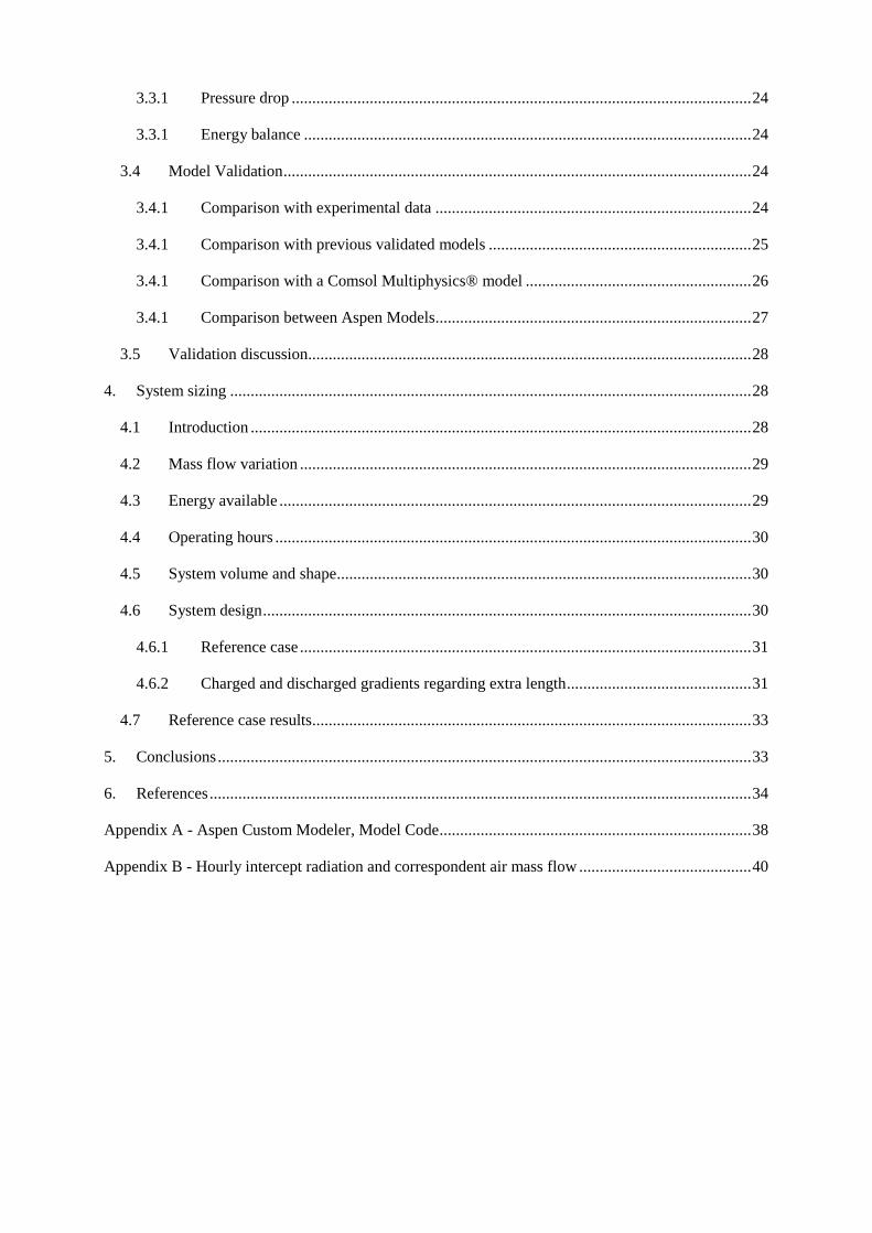
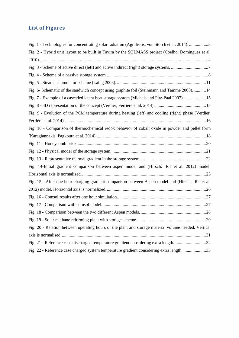

Layout and modeling of a high temperature heat storage system
Pedro Miguel Roda 3
Fig 1 - Technologies for concentrating solar radiation (Agrafiotis von Storch et al 2014)
112 CSP projects in Portugal
Portugal has a great potential to explore this type of technology In this chapter are shown two CSP
projects in Portugal
bull SOLMASS project
This project will build a 4MW solar tower power plant using a central receiver system
The plant will be constructed in Tavira Algarve as development platform (Coelho
Domingues et al 2010) This will be a hybrid unit and will use Biomass as backup A
layout of the hybrid unit can be seen in Fig 2
Layout and modeling of a high temperature heat storage system
Pedro Miguel Roda 4
Fig 2 - Hybrid unit layout to be built in Tavira by the SOLMASS project (Coelho Domingues et al
2010)
bull Parabolic salt loop project
The plant is of parabolic trough type and is already under construction in Eacutevora Portugal
The aim of the project is demonstrate the viability of this system using molten salt as
alternative heat transfer fluid (Muumlller-Elvers Wittmann et al 2012)
12 Environmental Profile
It is mandatory to assess the environmental impacts of CSP and even if they are less when compared
with conventional fossil fuelled technologies they cannot be neglected It is a fact that CSP greenhouse
gas emissions are lower than when compared with the same conventional plants although the CSP
impacts are local and can directly affected its surroundings Some of them such as water issues land
use energy and materials use and emissions will be reviewed in the following points
bull Water issues
In CSP water is used for cooling purposes Also the places rich in sun and water usually
are the most populated which means that a rational usage of water should be made An
alternative to water is to use air as cooling medium but it will affect the efficiency of the
process
Water in CSP is also used to keep the mirror cleaned and keep their reflective properties
although the amount of water used for cleaning purposes is much lower when compared
with amount used for coolingrect sunlight and hence are best constructed in arid or semi-
arid regions globally known as the Sun Belt
CSP are often designed to use water for cooling at the back-end of the thermal cycle
typically in a wet cooling tower A typical 50MW parabolic trough plants uses 04 ndash 05
million m3 of water per year for cooling (European Academies Science Advisory Council
2011) Vogel and Kalb (April 2010) also show that the dry cooling system increases the
Layout and modeling of a high temperature heat storage system
Pedro Miguel Roda 5
investment costs due to specific operating and maintenance costs of the system the Solar
Tower Juumllich (STJ) is an example of a facility using this system
bull Land use
Land use is the total area occupied by all the structures that belong and are needed to keep
the plant working In a CSP technology the collectors field is the structure that will
require a bigger area usually CSP are built in arid places that will have clear skies And
like any other energy technology it will also bring some visual effects on the nearer
populations even when CSP one technology that makes a relatively efficient usage of the
land occupied when compared to other solar technologies (Tsoutsos Frantzeskaki et al
2005) Table 1 shows a comparison between energy conversion technologies and CSP It
is presented in relation to the energy generated annually by each plant (European
Academies Science Advisory Council 2011)
Table 1- Land use comparison between energy conversion technologies (European Academies Science Advisory Council 2011)
Land use [m2(MWh-1 y-1)]
Parabolic solar power Spain 11
Solar tower power Spain 17
Photovoltaic power plant Germany 56 (photovoltaic power can also be placed on rooftops which
corresponds zero land use)
Wind power lt5
Biomass plantation France 550
Open-cast mining (lignite) Germany 60
High-voltage power transmission line across Europe 04
bull Energy and materials use
If a life cycle assessment is made of a CSP technology it is immediately noticed that the
greenhouse gas emissions are much lower than in conventional fossil fuelled power plants
although there are still some emission associated with CSP Most of these emissions are
related to the really high material use of CSP such as steel pipes and mirrors and if
storage is implemented the salts used as storage system
CSP greenhouse effects can increase if fuel backup is used because this is the only
situation that fuel is used in CSP technology (European Academies Science Advisory
Council 2011) and excepting these cases no fuel is used in CSP plants
13 Socio-Economic impacts
As it is mentioned before the impacts of CSP are mostly local this is also true for socio economic
impacts CSP technology needs some employees with high know-how but also need cleaning teams
and maintenance so the local market can benefit with the project Also the construction materials
since they are ordinary construction materials such as steel or concrete can be purchased in local
providers A lot of CSP projects are built in smaller towns or isolated places the local population can
benefit of an increase demand of ordinary goods and services
CSP costs vary with technology but the solar fieldrsquos costs represent the biggest cost of the project
There will be operation and maintenance costs and also costs with personnel It is extremely difficult
to make a comparison between conventional fossil fuelled power plants and renewable energy power
plants A usual methodology to compare costs of electricity generation between such technologies is to
calculate the ldquolevelised electricity costrdquo (LEC) which relates average annual capital and operating
costs of the plant to the annual electricity production (European Academies Science Advisory Council
2011) Table 2 illustrates the costs of generating technologies in 2010 (European Academies Science
Advisory Council 2011)
Layout and modeling of a high temperature heat storage system
Pedro Miguel Roda 6
Table 2- Illustrative costs of generating technologies in 2010 (currency conversion 2010 $euro = 0755) (European Academies Science Advisory Council 2011)
Technology LEC
[eurockWhe-1]
Capacity
[MW]
EPC cost
[eurokWe-1] Cap factor
Fuel costs
[eurockWhe-1]
OampMfix
[eurokW-1 y-1]
OampMvar
[eurockWhe-1]
CSP 100 MW
no storage
(Arizona)
179 100 3542 028 0 48 0
Pulverised coal
650MW base-
load
69 650 2391 090 29 27 03
Pulverised coal
650MW base-
load
90 650 2391 057 29 27 03
Gas combined
cycle mid-load 61 540 738 040 32 11 03
Wind on-shore
100MW 85 100 1841 03 0 21 0
Wind off-shore
400MW 153 400 4511 04 0 40 0
Photovoltaic
150MW
(Arizona)
212 150 3590 022 0 13 0
Analysing Table 2 it is easy to notice that there is a long way for renewable energy resources to
become competitive in the energy market Although with so many incentives and with the aim of
governments to turn fossil fuelled economies into clean energy economies And with the aim of
private investors to reduce their companies carbon foot print it is expected that a cost reduction by
scaling up renewable energy projects and technology innovations will turn renewable energy
resources into a competitive option (European Academies Science Advisory Council 2011)
14 Reforming process
141 Hydrogen production and methane reforming
Hydrogen production it is a process that is already being studied for a long time Hydrogen production
is mostly made by converting a material with high contents of hydrogen (H2) such as gasoline
ammonia or methanol into hydrogen rich flow This hydrogen can be later used in recent
technologies like fuel cells s an energy carrier and as an important ldquoraw materialrdquo in chemical
industries and refineries
Theoretically the hydrogen produced all around the world nowadays is produced by the catalytic
reforming of methane technique Different reactions can take place in methane reforming and two of
them are (1) steam methane reforming (SMR) and (2) CO2 (or dry) methane reforming (DMR)
(Agrafiotis von Storch et al 2014)
molkJHOHCH 206 CO3H 224 (1)
molkJHCOCH 247 CO22H 224 (2)
Both reactions are endothermic which means that an heat source is needed so that the reactions can
take place (Agrafiotis Von Storch et al 2014) Currently the hydrogen produced from fossil fuels is
used as a chemical in industrial processes
The reforming process as mentioned above needs energy to occur If solar energy (or any other
renewable energy resource) is used the process becomes free of fossil fuels and in this case the
production of solar fuels is achieved The process takes place in a range of temperatures from 800 to
1000degC which also means that there are already CSP technologies that can fit in this range
Layout and modeling of a high temperature heat storage system
Pedro Miguel Roda 7
2 Thermal storage Independently of the energy production technology it is a great advantage if the energy is coming from
a versatile dispatchable technology This property enables the technology to provide energy (almost)
on demand It is a fact that solar is a non-dispatchable technology and this represents one of the major
challenges on solar technology
In CSP there is the option to integrate a thermal heat storage system that could maintain the plant
working during cloudy periods and if the thermal storage capacity is big enough during night periods
Currently a lot of the researchers effort is to improve this systems and find one that is feasible and do
not compromise the efficiency of the process and do not increase the cost of the whole plant into
extremely high values
This chapter gives an overview on the different types of thermal storage concepts classification and
materials and their properties
21 Thermal energy storage concepts
There are different concepts for thermal heat storage systems Two groups can be identified active
and passive systems And active storage systems can be independently identified as direct or indirect
This type of classification is independent of the systemrsquos storage material and physical storage (Gil
Medrano et al 2010)
The decision on which type of technology will be used in a certain application depends on operation
temperature boundary conditions and development of the technology
211 Active direct and indirect storage systems
An active direct storage system is a more difficult system to implement because in this system the
storage material is also the heat transfer fluid which means that is necessary to find a material that can
be a good heat transfer fluid and a good storage material decreasing the options that can fit in both
An indirect storage system usually makes use of two different materials one is the heat transfer fluid
and other one is the storage material and by pumping the heat transfer fluid through a heat exchanger it
will heat up the storage material that is also being pumped Usually this is a more complex system in
terms of infrastructures because tanks are needed (Gil Medrano et al 2010) A scheme of these
concepts can be seen in Fig 3
Fig 3 - Scheme of active direct (left) and active indirect (right) storage systems
212 Passive storage systems
In a passive storage system the heat transfer fluid will be pumped through another medium that will be
the storage material in this system the storage material is not being pumped and the heat transfer fluid
is just used to charge or discharge the storage system (Gil Medrano et al 2010) A scheme of this
storage concept can be seen in Fig 4
Layout and modeling of a high temperature heat storage system
Pedro Miguel Roda 8
Fig 4 - Scheme of a passive storage system
The most common storage systems applied until now are the indirect storage system and the passive
systems (or regenerators) On the next section there will be a detailed description about the storage
medium and physical storage
22 Storage Media
The storage system can have different storage media such as liquid solid or gaseous the system can
also make use of different physical phenomena to store energy by heating up a medium without phase
change making use of a phase change of a material at a certain temperature or by chemical reactions
that are completely reversible
On the following sections a detailed description on each storage media and some of their applications
is presented
221 Sensible Heat Storage
Sensible heat storage means that the energy will be stored in a material without its phase change It is
important to make a wise choice of material as well as an intensive study of its behavior under
operating conditions The material can be liquid solid or gaseous and it will store energy accordingly
with (3) (Hasnain 1998)
∆11987612 = 119898 int 119888119901(119879)119889119879
1198792
1198791
(3)
2211 Sensible heat storage materials
As it is mentioned above the storage material choice is a crucial point in heat storage systems The
material has to have desired properties for the application And even when different physical heat
storage will be presented the storage materials will have a lot of properties in common A list of
desired properties of storage materials to be implemented in a sensible heat storage system are
Layout and modeling of a high temperature heat storage system
Pedro Miguel Roda 9
presented below and categorized in thermo-physical-(A) chemical-(B) mechanical-(C) economic-
(D) and environmental (E) properties (Khare DellAmico et al 2013)
(A)
bull High energy density
bull High thermal conductivity
bull High heat capacity
bull High density
bull Long thermal cycling stability
(B)
bull Long thermal chemical stability with no chemical decomposition
bull Non-toxic
bull Non-explosive
bull Low corrosion potential or reactivity to heat transfer fluids
bull Compatible with materials of construction
(C)
bull Good mechanical stability
bull Low coefficient of thermal expansion
bull High fracture toughness
bull High compressive strength
(D)
bull Cheap and abundant materials
bull Low cost of manufacturing into suitable shapes
(E)
bull Low manufacturing energy requirement
bull Low CO2 foot print
After evaluating the properties requirements for a certain application a short list of materials should be
elaborated and the materials should be intensively studied Find if the material deteriorates under
operating conditions feasibility and thermal behavior For high temperature applications the most
promising materials are ceramics and metals (Khare DellAmico et al 2013)
2212 Sensible heat storage concepts
The two main concepts of sensible heat storage systems are solid and liquids which will be explained
in detail on the following points
bull Solids
Chose a solid material as a storage the storage material is usually a choice based on its low
cost When solids are used ordinarily concrete leakages phase changes freezing or
evaporation problems are not faced On the other hand solids durability degradation after
several cycles of use and their low thermal conductivity represent the biggest
disadvantages of this concept (Shukla 1981)
Layout and modeling of a high temperature heat storage system
Pedro Miguel Roda 10
bull Liquids
Liquids have the high thermal conductivity as their big advantage but for high
temperatures they have to be pressurized Freezing and boiling points are the biggest
challenges on sensible heat storage systems using liquids as storage material which also
makes it a more difficult storage material to store (Shukla 1981)
There are already few systems implemented under investigation or in test campaigns On the
following sections some examples of both concepts are presented
2213 Examples of sensible heat storage systems
bull Concrete
Concrete is a tempting option since it is a relatively cheap material it is widely use around
the world and it is abundant
The systems using concrete as storage material consist of concrete block that is crossed by
a tube matrix The heat transfer fluid flows through the tubes and heats up the concrete
block This concept has already been tested and concrete showed a great durability
performance Although the system requires a huge area to be installed and its low thermal
conductivity has to be improved which represent the biggest disadvantages of the system
Thermal stability of concrete was evaluated but only for temperature ranges of 400 -
500degC For this temperature ranges a concrete storage test module was built and tested in
The system was tested in a temperature range between 400 - 500degC in Stuttgart
Germany (Laing Bahl et al 2012) A system sizing determination for the parabolic
through solar thermal power plant of the ANDASOL-type was calculated and a 50000 m3
is required and has to be built in a modular approach (Laing Bahl et al 2012)
Some solutions for the poor thermal performance due to concretersquos low thermal
conductivity (range 12 ndash 145 W m-1
K-1
) were investigated and an improvement of
around 15 was achieved by adding structures with high thermal conductivity (Laing
Steinmann et al 2008)
bull 2 Tank molten Salt Indirect Storage
The two tank system is one of the most storage systems implemented This system uses
liquid as the storage media This heat storage system consists of 2 tanks one hot tank and
one cold tank During charging the salt from the cold tank is pumped through the heat
exchanger and is heated up by the heat transfer fluid and stored in the hot tank During the
discharging cycle the direction is reversed and the hot salt heats up the heat transfer fluid
and is stored in the cold tank If the heat transfer fluid is also used as storage material the
heat exchanger is not needed in the systems
This is system was successfully tested in the Solar Two project and its operating
temperatures are between 290-390degC using a molten salt mixture This system is always
limited by the molten salt allowable operating temperatures because the mixture cannot
freeze inside the tanks or pipes system it limits the lowest temperature And since
corrosivity increases with the temperature for molten salts tankrsquos materials have to be
chosen carefully And the mixturersquos thermal performance can be affected in higher
temperatures (Kolb 2011 Dunn Hearps et al 2012)
bull Steam accumulator
Steam accumulators systems are storage systems for short periods that solar radiation is
not available like cloudy periods since accumulators deliver the energy stored quickly
and its cost are proportional to the pressure vessel used in the system
Steam accumulators make use of the high water thermal conductivity property and since
water is not liquid above 100degC for CSP applications it has to be pressurized The system
Layout and modeling of a high temperature heat storage system
Pedro Miguel Roda 11
is charged by providing steam to the liquid medium of the steam accumulator that will
increase the liquid water temperature For discharging the pressure is lowered and steam
is generated A scheme of this system is presented in Fig 5
Fig 5 - Steam accumulator scheme (Laing 2008)
bull Packed bed (and regenerators)
In a packed bed system the heat transfer fluid flows through a container that is full with
small particles made of materials with high thermal conductivity Regenerators are
structures with high thermal conductivity and the heat transfer fluid flows through them
The regenerator concepts is a known system from the aluminum industry that is carried
out at temperatures around 1100degC usually using ceramics materials
This type of system is implemented in the STJ in Juumllich where is used as heat transfer
fluid and alumina is the storage material and its properties are shown in Table 3 The
storage and heat transfer fluid are in direct contact during chargingdischarging process
The air flows through small channels this structure is typically called honeycomb brick
(Zunft Haumlnel et al 2011) The system has already been tested under operating conditions
between asymp200- 630degC (in March 2010) and it has a good thermal performance delivering
air almost at constant temperature when discharging (Zunft Haumlnel et al 2011)
A pebble bed regenerator was investigated by Fraunhofer UMSICHT making use of
extremely small spherical materials (3 to 12 mm diameter) if alumina oxide pebbles are
used the system can reach high temperatures since the maximum operating temperature
for this material is 1800degC (Daschner Binder et al 2013)
Table 3 - Material characteristics
Honeycombs
Material Alumina porcelain (C130)
Specific heat capacity 088 kJ(kgK)
Thermal conductivity 21 W(mK)
222 Latent heat storage
Latent heat storage systems make use of the release of heat during a phase change of a material This
concept has the advantage that it can occur almost at a constant temperature The process should be
reversible so the material will not change its properties after several cycles It is also mandatory that
all the material can be converted to the previous phase completely (Hasnain 1998) In this system it is
even more crucial an accurate choose of material that can fit to the specific application
Layout and modeling of a high temperature heat storage system
Pedro Miguel Roda 12
2221 Material to be used as PCM
It is expectable that the most investigated phase transition would be the transitions that release more
energy although the early investigations began with the phase change solid-liquid that usually releases
less energy than the liquid-vapor transitions This is explained that a better container is needed and
also leaking problems are more likely to happen when leading with gases (Abhat 1983)
As it is mentioned above the material should match the specific operating temperature range almost
perfectly The properties of the material even that they are similar to the properties of the materials
used for sensible heat they should have some specific performance due to their phase change usage
The thermodynamic (A) kinetic (B) chemical (C) and economic (D) criteria used to evaluate PCM
materials are (Abhat 1983)
The phase change material (PCM) should possess
(A)
bull A melting point in the desired operating temperature range
bull High specific latent heat of fusion
bull High density which reduces the container (storage) volume
bull High specific heat capacity to provide for significant additional sensible heat storage
effects
bull Congruent melting the material should melt completely so that the liquid and solid phases
are identical in composition otherwise the difference in densities between solid and
liquid cause segregation resulting in changes in the chemical composition of the material
(Abhat 1983)
bull Small volume changes during phase transition so that a simple containment and heat
exchanger geometry can be used (Abhat 1983)
(B)
bull Little or no super cooling during freezing the melt should crystallize at its thermodynamic
freezing point This is achieved through a high rate of nucleation and growth rate of the
crystals (Abhat 1983)
(C)
bull Chemical stability
bull No chemical decomposition so that a high latent thermal energy storage system life is
assured (Abhat 1983)
bull Non-corrosiveness to construction materials
bull The material should be non-poisonous non-flammable and non-explosive
(D)
bull Available in large quantities
bull Inexpensive
In order to evaluate the properties of the material after several cycles under operating conditions the
melting and freezing characteristics of the material should be evaluated before Abhat (1983) suggests
Layout and modeling of a high temperature heat storage system
Pedro Miguel Roda 13
that two measurement techniques can evaluate these characteristics Differential Scanning Calorimetry
and thermal analysis
Table 4 gives a summary of phase change materials A more complete and detailed list of phase
change materials is presented in Caacuterdenas and Leoacuten (2013) work
Table 4 - Melting temperature for different compounds
Temperature range
[degC] Material
Transition
temperature [degC] Heat of fusion [kJkg]
0 -100
Water
Paraffin
Salt hydrate
0
20-60
30-50
335
140-280
170-270
100-400
AlCl3
LiNO3
Na2O2
192
250
360
280
370
314
400-800
50LiOH50LiF
KClO4
LiH
427
527
699
512
1253
2678
800-1500
LiF
NaF
MgF2
Si
868
993
1271
1415
932
750
936
1654
The storage capacity of a latent heat storage system in phase transition solid-liquid is given by (4)
(Portaspana 2011)
Tm
Ti
Tf
Tm
pmmp dTCmhadTCmQ (4)
2222 Latent heat storage systems
It is mentioned in the previous section that latent heat storage systems have the advantage that the
process of charging and discharging can be carried out in an almost isothermal condition making use
of the heat released or consumed by phase change Although most of the phase change materials have
low thermal conductivity In order to have an efficient latent storage system this property has been
investigated recently and a lot of investigators try to find a solution to improve it (Caacuterdenas and Leoacuten
2013)
A popular project that presented some solutions for the challenges in latent heat storage systems is the
DISTOR project (Steinmann and Tamme 2008) The solutions presented in the project are
bull Extended heat transfer area
This approach suggests that if the heat transfer fluidrsquos container area in contact with the
PCM is larger the phase change will occur faster because the distance for heat transfer
between the container and the solid PCM is reduced
bull Composite material with increased thermal conductivity
Materials with extremely high thermal conductivity are added to the PCM
Some applications using these solutions are presented on the following section
Layout and modeling of a high temperature heat storage system
Pedro Miguel Roda 14
2223 Examples of latent heat storage systems
bull Sandwich design
Typically latent heat storage systems consist of a tube (or container) where the heat
transfer fluid is flowing and this tube is in contact with the phase change material When
charging usually the phase change material is changing its phase from solid to liquid If
the thermal conductivity of the phase change material is low the process is much slower
and inefficient and what can occur is that part of the material is still solid by the end of the
charging period
The sandwich design consists in the addition of a structure in between of the phase
change material with high thermal conductivity These structures are added in parallel to
to each other and perpendicular to the tube containing the heat transfer fluid (Steinmann
and Tamme 2008)
Fig 6 shows the scheme of a storage unit of the sandwich concept Foils made of
exfoliated graphite are combined with PCM to form a sandwich structure
Fig 6- Schematic of the sandwich concept using graphite foil (Steinmann and Tamme 2008)
Cascaded PCMs
The latent heat storage systems as it is mentioned before make use of a phase change in a
material that occurs almost at constant temperature The performance of these systems
depends on the temperature difference between the PCM and the heat transfer fluid During
charging process the heat transfer fluid is transferring heat to the PCM that is changing its
phase although the heat transfer fluid will also decrease its own temperature Which means
that until the heat transfer fluid leaves the system on the outlet the process is less efficient on
the end part of the system (if we only consider along the x axis)
Some investigations suggest that if the difference between the PCM and the heat transfer fluid
is kept constant along the whole process the system has a much better performance What the
Layout and modeling of a high temperature heat storage system
Pedro Miguel Roda 15
investigations suggest is that a series of PCM is placed in series next to each other where the
phase change temperature is lowering from the left (inlet during charging) to the right (outlet
during charging) this temperature is constant along the whole process and a constant heat flux
is also achieved this approach is usually called cascaded PCM (Jegadheeswaran and Pohekar
2009) Fig 7 shows an example of a cascaded heat storage system
Fig 7 - Example of a cascaded latent heat storage system (Michels and Pitz-Paal 2007)
Experimental investigations with three PCMs sodium nitrate NANO3 a eutectic mixture of
potassium nitrate and potassium chloride KNO3KCl and potassium nitrate KNO3 were
carried out by (Michels and Pitz-Paal 2007)
Michels and Pitz-Paal (2007) work show that when this approach is used a bigger amount of
PCM changes its phase when compared with systems that only use a single PCM they
determined that when using the cascaded approach the PCM material that experiments a phase
change is around 92 during charging process and 67 during discharging process Even
when using a single PCM that the whole material experiences a phase change during charging
process during discharging process only 2 of the material experiences a phase change
Lithium carbonate Li2CO3 prototype
This prototype uses Lithium carbonate Li2CO3 as PCM material and makes uses of copper to
improve the thermal performance of the PCM Verdier Ferriegravere et al (2014) performed
numerical simulations that can be analyzed The system is in equilibrium ate the beginning
and is set on a uniform temperature of 700degC To charge the system a temperature of 900degC is
set as boundary condition on the bottom part of the structure To evaluate the discharging
process of the system a boundary condition of 100degC is set on the bottom of the structure and
before the discharging process begins a uniform temperature of 900degC is assumed for the
system The concept of the system analyzed is showed in Fig 8
Fig 8 - 3D representation of the concept (Verdier Ferriegravere et al 2014)
Layout and modeling of a high temperature heat storage system
Pedro Miguel Roda 16
The numerical results are shown in Fig 9
Fig 9 - Evolution of the PCM temperature during heating (left) and cooling (right) phase (Verdier
Ferriegravere et al 2014)
T1 T3 T5 and T7 are temperatures closer to the fin and T2 T3 T4 and T8 are located in the
center of the compartment
Fig 9 shows the results of the numerical investigations performed by Verdier Ferriegravere et al
(2014) Here a comparison with a system using only PCM without the copper fins was not
made So the only results that can be evaluated is that the system takes around 4h to be
completely charged and 25h to be completely discharged
More investigations and comparisons between traditional latent heat storage systems and system with
the integration of material with high thermal conductivity should be made to really determine its
advantages and influences on the system
223 Thermochemical heat storage
On thermochemical heat storage it is taken advantage of enthalpy but instead of a phase change like in
latent heat storage this system makes use of the completely reversible endothermic chemical
reactions The concept of this system is to absorb the excess heat in an endothermic reaction and store
the products on separate containers During discharging the products are combined exothermically and
the heat of reaction can be used
These systems are far behind in maturity when compared with sensible or latent heat storage systems
but they represent a promising solution due to their high energy density and by the possibility to store
energy at ambient temperature
Like the other systems presented above a proper choice of the materials should be evaluated on the
next section the material choice and properties are presented
2231 Properties of reactions considered for thermochemical energy
storage systems
On thermochemical the properties are related to compounds and reactions On this type of storage
systems the properties chased are even more peculiar and crucial
Necessary properties of the compounds to be used as thermochemical heat storage as told in
Portaspana (2011) work are
Reversibility
No side reactions or changes in reaction rate with the time should occur The reaction should
be completely reversible (Portaspana 2011)
Layout and modeling of a high temperature heat storage system
Pedro Miguel Roda 17
Reaction rates
Both forward and reverse reactions must be rapid enough to absorb all the available energy or
release it promptly The reaction rates must not decrease with cycling Such a decrease can be
observed if structural changes of the storage medium occur (Portaspana 2011)
Controllability
The reactions must be controllable because they have to be turned on and off when required
Controllability is achieved by product separation by controlling the temperature and pressure
or by catalysts (Portaspana 2011)
Ease of storage
The reaction products have to be easily separable prior to storage Reactions must not occur at
storage temperature (Portaspana 2011)
Safety
Toxicity inflammability and corrosiveness of the reaction products may pose unacceptable
safety hazards (Portaspana 2011)
Cost
Cost should be as low as possible which requires materials which are readily available
(Portaspana 2011)
On the following section will be presented some reactions considered for thermochemical heat storage
2232 Examples
Ammonia dissociation
When a thermochemical heat storage system is being implemented it will occur in a reactor
An important detail when evaluating promising reactions is if the process is already well-
known in other applications This is the case of ammonia dissociation reaction (5) the heat
recovering reaction is the well-known Haber Bosch process usually employed for fertilizer
production Ammonia dissociation has other advantages such as no side reactions occur and it
consists of no aggressive reactants for the environment On the other hand ammonia
dissociation has a relatively low enthalpy of reaction around 665 kJmol (Lovegrove Luzzi
et al 1999) Most of the studies on this reaction as a heat storage system have been carried out
by the Australian National University
223
2
3
2
1HNHNH
(5)
Reduction and oxidation reactions
This is a two-step concept that makes use of the principle of transition between the oxidized
and reduced form of an oxide of a metal that has multiple oxidation states (Agrafiotis Roeb et
al 2014)
On the first step an endothermic reaction (6) takes place with the supply of external heat the
reduced state of the oxide MeOox is obtained as a product (Agrafiotis Roeb et al 2014) The
general reaction is
)()( 2 gOMeOHMeO redox (6)
On the second step an exothermic reaction (7) takes place via an oxygen source If air is used
as the oxygen source the oxidation reaction is as the same structure as (Agrafiotis Roeb et al
2014)
Layout and modeling of a high temperature heat storage system
Pedro Miguel Roda 18
)()(2 HMeOgOMeO oxred (7)
Agrafiotis Roeb et al (2014) present the relevant reversible reactions considered for
thermochemical processes as scheme (8) for metal hydroxides scheme (9) for carbonates and
scheme (10) for oxides
reactmolkJHOHCaOHOHCa 100 )()( 22 (8)
reacmolkJHCOCaOHCaCO 167 )( 23 (9)
reacmolkJHOCoOHOCo 200
2
13)( 243
(10)
Heating cycles between 985 and 785degC were performed by Tescari Agrafiotis et al (2014) in
Co3O4 as well as Co3O4 ndash based binary powder metal oxide compositions under air They
showed on their work that the reactions are completely reversible Tescari Agrafiotis et al
(2014) investigated an hybrid system This hybrid system consists of coating a typical
honeycomb sensible heat storage system The investigation suggests that the system will have
a similar behavior to the plain powder thermochemical system and will improve the ceramic
honeycomb system by increasing the amount of energy stored by the system
Cobalt oxide powder was compressed and become a cobalt oxide pellet and was tested by
Karagiannakis Pagkoura et al (2014) Their work shows that the pellet can slightly improve
the performance of the chemical reaction The results for powder and pellet can be seen in Fig
10
Fig 10 - Comparison of thermochemical redox behavior of cobalt oxide in powder and pellet form
(Karagiannakis Pagkoura et al 2014)
In Fig 10 the red line represents the cobalt oxide pellet and the blue line represents the
powder And by analyzing the peaks it is possible to understand that it is possible to operate in
a wider range of temperatures and recover more heat from the reaction
Miguel Gonzalez-Aguilar et al (2014) are on the early investigations for a fluidized bed
system considering the manganese (III) redox reaction showed in (11)
3224332 OMn of 831 46 molkJHOOMnOMn (11)
Sulfur based thermal energy storage
This thermochemical storage concept consists on storing energy by producing elemental sulfur
for later burning To produce elemental sulfur on a thermochemical process three chemical
reactions take place (12) concentrated sulfuric acid is decomposed by heat into water sulfur
dioxide and oxygen (13) sulfur dioxide undergoes disproportionation in water into sulfuric
Layout and modeling of a high temperature heat storage system
Pedro Miguel Roda 19
acid and elemental sulfur (14) the sulfur generated is directed to storage andor to a sulfur
burner for combustion to generate heat The thermochemical cycle does not produce waste
effluent and does not emit greenhouse gas into the environment (Bunsen Wong 2013)
molkJHgSOgOgOHH 97 )(2)()(2(l)SO2H Decomp SO 222 4242 (12)
)((aq)SO2H)(3 O(l)2H ionDisproport 42222 lsSgSOSO (13)
molkJHgOlsSS 297 (g)SO)( )( Combustion 22 (14)
3 Mathematical model
31 Introduction
In this chapter the thermal interaction between the heat transfer fluid and the storage material of the
system is studied mathematically
The system studied is similar to the one installed in the STJ (Zunft Haumlnel et al 2011) using air as
heat transfer fluid and alumina as storage material
The model objective is to simulate a dynamic state of the thermal storage system during charge and
discharge process as well as to switch between these processes in a continuous simulation run This
ability of switching between charging and discharging conditions in one simulation is of crucial
importance in order to enable the complete simulation of the solar methane reforming plant where the
model will be integrated Determining the relation between the total volume of the storage system and
the number of hours that it can provide heat to operate the plant is also a goal of this work
The model discretizes the storage in a large number of interacting layers providing detailed
information about the temperature distribution within the storage Air flows through the honeycomb
bricks channels to transport the heat to or from the storage The convective heat transfer coefficient
between air and solid is sufficiently large which leads to a small temperature difference between air
and solid during charging or discharging of the system
The storage model presented in this work assumes an ideal storage which means that no heat losses
are taken into account during charging or discharging period During standstill period (when air is not
flowing through the channels) the temperature gradient will remain the same until the next charging or
discharging period starts again
The temperature dependent properties of air and the pressure loss by forced convection have been
considered in this model
The storage model is implemented in Aspen Custom Modelerreg with the appropriate syntax shown in
Appendix A - Aspen Custom Modeler Model Code
In order to reduce the computations time only a single channel of one honeycomb brick is simulated
The same conditions are assumed for each parallel channel so that all the channels will have a similar
behavior since no heat losses to environment are considered The energy stored by the system is then
the product of number of channels by the energy stored in only one channel
Layout and modeling of a high temperature heat storage system
Pedro Miguel Roda 20
311 Storage structure
As mentioned in the previous sections the system modeled is similar to the system installed in STJ
The system installed in STJ consists of a storage chamber made of honeycomb storage elements as
shown in Fig 11
The model will only consider the volume of material capable of storing energy which is the volume of
honeycomb bricks excluding the housing and insulation material The model does not consider any
degradation after a long operating period
311 Storage system general properties
The storage installed in STJ is a regenerator-type Air flows from the top to the bottom of the system
in direct contact with the alumina structure during charging period During discharging the air flow is
reversed
The system installed in STJ is a block with a volume of 120m3 and a height of 3m and operates
between 680 and 120degC with a nominal charge mass flow of 94 kgs Table 5 is a summary of the
storage specifications (Zunft Haumlnel et al 2011)
Table 5 - Storage specifications
Storage specifications
Temperature
range
680 ndash 120 degC
Charge mass
flow
94 kgs
Pressure loss lt1500 Pa
The storage material used is alumina porcelain (C130) and its thermophysical properties are shown in
Table 6 (Zunft Haumlnel et al 2011)
Table 6-Alumina porcelain (C130) properties
Honeycombs 60 x 60 channels
Brick dimensions 15 x 15 x 15 cm
Mass density 2700 kgm-3
Specific heat capacity 088kJ(kg-1K-1)
Themal conductivity 21 W(m-1K-1)
Heating surface 1180 m2m-3
Fig 11 - Honeycomb brick
Layout and modeling of a high temperature heat storage system
Pedro Miguel Roda 21
311 Honeycomb storage principle
The principle of the honeycomb ceramic is identical to other sensible heat storage During the
charging period the hot air flows through the systems micro-channels and releases heat increasing the
material temperature During the discharging period the flow direction is reversed and then cold air
flows through the systems micro channels and absorbs the heat stored in the material resulting in an
increase of the air temperature
As Luo Wang et al (2013) showed the honeycomb ceramic have an excellent heat transfer
characteristic resulting from the larger heat exchange area and fine flow behavior meaning relatively
small pressure drop resulting from the flow-through channels
32 Physical model
Fig 12 shows the physical model which consists of a quadrangular channel with length L and opening
s During the charging process heated air flows through the channel from top to bottom of the
channel During the discharging process the air flow is reversed and cold air is pumped from the
bottom to the top of the channel
The channel is discretized in a certain amount of points between 0 and L with the same spacing
between each other The spacing between each point will return more or less accurate results for a
smaller and larger spacing respectively The spacing will also influence the simulation time so a
optimal situation should be determined where a not so time consuming simulation can be carried out
with reasonable accurate results
Fig 12 - Physical model of the storage system
A temperature gradient is achieved during both processes and the system is considered completely
charged when the air temperature in the outlet exceeds the defined minimum temperature that should
usually be defined according to the outlet temperature of the process ie heat exchangers that the heat
is used in In opposite the system is considered completely discharged when the air outlet temperature
during discharge decreases below the required higher temperature level A representative scheme of
the thermal gradient in the system is shown in Fig 13
Layout and modeling of a high temperature heat storage system
Pedro Miguel Roda 22
Fig 13 - Representative thermal gradient in the storage system
33 Governing Equations
The storage system modeled is a regenerator-type heat storage A regenerator is a type of heat
exchanger in which the hot and cold-fluids occupy the same physical space but at different times
Regenerators necessarily operate in a transient mode The temperatures throughout the system depend
upon time as well as on position Partial differential equations are needed to describe the time and
spatial dependence of the temperature of the solid and the fluid These equations can be identified
using energy balances on the fluid and solid (Nellis and Klein)
The energy equations used to describe the model follow the descriptions and assumptions listed below
Ideal behavior of the system the amount of energy recovered is the same as the amount
stored
The fluid flow inside the storage is vertical from top to bottom during charging and from
bottom to top during discharging
The fluid thermophysical properties are temperature and pressure dependent
The solid thermophysical are temperature independent
There is no heat generation or dissipation inside the storage
The system is well insulated and there are no losses to the ambient
Pressure drop along the channel is considered
The system is one dimensional only temperature gradients along the x axis
The energy equation for the fluid (15) is written as
119899119886119894119903 sdot 119888119901119886119894119903 sdot (
120597119879119886119894119903
120597119909) + 120588119886119894119903 sdot 119888119901119886119894119903 sdot 119860119888119904119886119894119903 sdot (
120597119879119886119894119903
120597119905) = 4 sdot 120572 sdot 119904 sdot (119879119886119894119903 minus 119879119904119900119897)
(15)
The first term on the left side of the equation corresponds to the enthalpy associated with the fluid
flow The second term on the left side of the equation corresponds to the rate of change of enthalpy
The term on the right side of the equation corresponds to the heat exchange by convection between the
solid and the fluid The conduction in the fluid can be neglected due to the small value of air
conductivity
The energy equation for the solid (16) is written as
Layout and modeling of a high temperature heat storage system
Pedro Miguel Roda 23
120588119904119900119897 sdot 119888119901119904119900119897 sdot 119860119888119904119904119900119897 sdot (
120597119879119904119900119897
120597119905) = 119860119888119904119904119900119897 sdot 119896119904119900119897 sdot (
1205972119879119904119900119897
1205971199092 ) + 4 sdot 120572 sdot 119904 sdot (119879119886119894119903 minus 119879119904119900119897) (16)
The term on the left side of the equation corresponds to the change of enthalpy of the solid The first
term on the right side of the equation corresponds to the heat transferred by conduction in the solid
along the x axis The second term on the right side corresponds to the heat transferred by convection
between the particles and the fluid
It is necessary to evaluate the convective heat transfer coefficient α to determine the heat transferred
by convection The convective heat transfer coefficient is affected by the state of the flow and the
shape of the duct and can be determined by (17) using the appropriate Nusselt correlation The heat
transfer convective coefficient is determined locally by the model
120572 =
119873119906 sdot 120582119886119894119903
119904
(17)
In order to use the appropriate correlations an evaluation of the flow state is needed this evaluation is
determined by the Reynolds number A flow is laminar if Re le 2400 and turbulent if Re ge 4000 in
between the flow is in a phase called transition (Yunus and Cimbala 2006) In the presented model the
Reynolds number range is from asymp7 ndash 12 meaning that the flow is in laminar phase The appropriate
Nusselt correlation is a correlation that gives the Nusselt number for a fully developed laminar flow
transferring heat to four walls in a quadrangular duct (18) (Shah and London 1978) which depends on
the side length of the duct entry cross section
119873119906 = 8235 [1 minus 20421 sdot 119886 + 30853 sdot 1198862 minus 24765 sdot 1198863 + 10578 sdot 1198864
minus 01861 sdot 1198865]
with 119886 =119888
119889
(18)
119886 represents the relation between the side length of the duct entry cross section and it is equal to one
for quadrangular ducts
331 Boundary and initial conditions
The temperature in the fluid and solid can be determined by (15) and (16) respectively The solution
of the temperatures depends on the physical conditions existing at the boundaries of the system An
initial condition is also needed since the system is also time dependent
The boundary condition to solve the fluid equation (15) is
The air inlet temperature is constant for all time
119879(0 119905) = 119879119886119894119903119894119899 (19)
The boundary conditions to solve the solid equation (16) are
In the first layer of the solid (since there is no previous layer) the conduction is only to the
next layer so the second derivative term becomes a first order derivative term
120588119904119900119897 sdot 119888119901119904119900119897 sdot 119860119888119904119904119900119897 sdot (
120597119879119904119900119897
120597119905) = 119860119888119904119904119900119897 sdot 119896119904119900119897 sdot (
120597119879119904119900119897
120597119909) + 4 sdot 120572 sdot 119904 sdot (119879119886119894119903 minus 119879119904119900119897)
(20)
In last layer of the solid (since there is no next layer) the conduction is only form the previous
layer so the second derivative term becomes a first order derivative term
120588119904119900119897 sdot 119888119901119904119900119897 sdot 119860119888119904119904119900119897 sdot (
120597119879119904119900119897
120597119905) = 119860119888119904119904119900119897 sdot 119896119904119900119897 sdot (
120597119879119904119900119897
120597119909) + 4 sdot 120572 sdot 119904 sdot (119879119886119894119903 minus 119879119904119900119897)
(21)
Layout and modeling of a high temperature heat storage system
Pedro Miguel Roda 24
The initial conditions at the beginning of the simulation are defined by the solid temperature
The system is in equilibrium and the fluid temperature inside the channel is equal to the solid
temperature
119879119886119894119903(119909 0) = 119879119904119900119897(119909 0) (22)
331 Pressure drop
Pressure drop is a quantity of interest since it is directly related to the power requirements of the fan or
pump to maintain flow which will be further considered when the model is implemented in the solar
methane reforming plant model
The pressure drop inside the channel is considered and was determined by (23) from Yunus and
Cimbala (2006)
∆119901 = 119891 sdot
119871
119863sdot
120588119886119894119903 sdot 1198811198861198941199032
2+ 120588119886119894119903 sdot 119892 sdot 119871
(23)
119891 is the Darcy friction factor and it is defined as (24) for fully developed laminar flow in a
quadrangular duct
119891 =
5692
119877119890 119877119890 =
119881119863
120584 119886119899119889 119877119890 le 2300
(24)
331 Energy balance
In order to make sure that the energy gain by the wall during charging process or the energy loss by
the wall during discharging process is the same as the air enthalpy change and make sure that the
model does not violate the first principle of thermodynamics (conservation of energy) two monitoring
variables were created and their values compared
These two variables are the solid enthalpy change determined by (25) and the air enthalpy change
(26)
119876119904119905119908119886119897119897 = 120588119904119900119897 sdot 119888119901119904119900119897 sdot 119860119888119904119904119900119897 sdot 119871 sdot (
120597119879119904119900119897
120597119905)
(25)
119876119886119894119903 = 119899119886119894119903 sdot [ℎ119886119894119903(119871) minus ℎ119886119894119903 (0)] (26)
34 Model Validation
Is necessary to check the model performance with already existing validated models or compare the
model with experimental data In order to compare the model with experimental data it is necessary to
recreate the model as much close to the real system
To validate this model experimental data and previous works from the system installed in STJ are
available (Zunft Haumlnel et al 2011 Kronhardt Alexopoulos et al 2014) To validate the model the
same properties from the system installed in the STJ are implemented in the model
A comparison between the model implemented in Aspen Custom Modeler and a model built in
Comsol Multiphysicsreg will also be shown in this chapter
341 Comparison with experimental data
A test campaign was performed by Zunft Haumlnel et al (2011) in March 2011 These experiments had
the goal to evaluate the storage performance and the validation of existing simulations and design
tools
Layout and modeling of a high temperature heat storage system
Pedro Miguel Roda 25
The experiments include charging period standstill and discharging performance of the storage
system Different inlet air temperatures and different inlet mass flows were tested and measured in the
test campaign The experimental data is not published in detail
The measured data was difficult to interpret and due to lack of information regarding the
thermocouples location it was not possible to achieve the correct interpretation of the measured data
and it was not also possible to establish a comparison between the model presented in this work and
the test campaign performed by Zunft Haumlnel et al (2011)
341 Comparison with previous validated models
The model presented by Hirsch IRT et al (2012) was validated using measured data from the system
installed in STJ The test boundaries as mass flow inlet temperature and inlet pressure are the
nominal solar tower process values showed in Table 5 The initial temperature gradient inside the
system presented by Hirsch IRT et al (2012) was determined by interpolation of the real temperature
of the storage (this initial gradient is not the discharged gradient it is just the reference point before
one hour charging period) Under these conditions this model is appropriate for validation of the
model created in this work
The comparison between the initial gradient in our model and the model by Hirsch IRT et al (2012) is
shown in Fig 14 The results show a good agreement
Fig 14-Initial gradient comparison between aspen model and (Hirsch IRT et al 2012) model
Horizontal axis is normalized
Another comparison is shown in Fig 15 this comparison is the systems profile temperature after one
hour charging Once again the presented model and the model presented by Hirsch IRT et al (2012)
show a good agreement The deviations can be due that in our model a constant inlet mass flow and
inlet temperature is assumed for the whole hour leading to no oscillations Also the difference in the
initial gradient leads to higher deviations between the two models It is expected that when the system
reaches a periodic steady state operating conditions the deviations are reduced
0
100
200
300
400
500
600
700
800
0 011 022 033 044 055 066 077 088 099
Tem
per
ract
ure
[degC
]
System height (normalized)
TAMM
Hirsch IRT et al (2012)
Layout and modeling of a high temperature heat storage system
Pedro Miguel Roda 26
Fig 15 - After one hour charging gradient comparison between Aspen model and (Hirsch IRT et al
2012) model Horizontal axis is normalized
341 Comparison with a Comsol Multiphysicsreg model
The model presented in this work simulates the behavior of one channel of the whole system A
channel of the whole system is a certain number or honeycomb bricks disposed in series on top of each
other until it reaches 3 meter high In our model to achieve the 3 meter height 20 models are connected
in series since every honeycomb brick has 15cm length as shown in Table 6
Aspen Custom Modelerreg is a powerful tool and enables to perform complex calculations and
simulations using a simple syntax and in short period of time Comsol Multiphysicsreg model is also a
powerful tool and also enables the creation of a 3D picture of the system In order to get a better
understanding of the system a simple Comsol Multiphysicsreg model was created
Comsol Multiphysicsreg model
The comsol model consists of a honeycomb channel The alumina properties applied are the same
shown in Table 6 and the air themophysical properties are temperature dependent
The boundary conditions applied in the Comsol model are
Constant inlet temperature of 680ordmC
Adiabatic outer walls of the channel
Constant inlet pressure
Outlet velocity asymp006 ms
The system is in an equilibrium state of 150ordmC in the beginning The system is evaluated after one hour
under these conditions and results are presented in Fig 16
0
100
200
300
400
500
600
700
800
0 011 022 033 044 055 066 077 088 099
Tem
per
ract
ure
[degC
]
System height (normalized)
TAMM
Hirsch IRT et al (2012)
Layout and modeling of a high temperature heat storage system
Pedro Miguel Roda 27
Fig 16 - Comsol results after one hour simulation
When this model is compared with the model created in Aspen that need to be connected in series the
results shown a good agreement with slight deviations The results curves are shown in Fig 17 In Fig
17 Tcomsol corresponds to the Comsol model data TAMM corresponds to the model created in
Aspen where several models are connected in series and TALCM corresponds to the model created in
aspen where a single long channel is simulated
Fig 17 - Comparison with comsol model
341 Comparison between Aspen Models
The model presented in this work shows a good agreement with validated models using measured
data But in order to implement our model in the complete solar methane reforming process model this
connection of blocks is extremely difficult to handle when a transient simulation is carried out due to
the fact that the charging outlet becomes the inlet during discharging of the system In order to
simplify this issue a single model of 3 meter height was created The main difference between a model
of 3m length and 20 models of 15cm length connected in series is that in the 3m length single model
thermal conduction between 2 consecutive bricks occurs
0
100
200
300
400
500
600
700
0 002 004 006 008 01 012 014
Tcomsol
TAMM
TALCM
Layout and modeling of a high temperature heat storage system
Pedro Miguel Roda 28
In order to make sure that thermal conduction between consecutive bricks will not lead to inaccurate
results the two aspen models are compared The curve of the first 15cm of the long channel aspen
model (represents the first brick) is also plotted in Fig 17 In the end of the curve a slight deviation
from the Comsol model and the aspen multiple bricks model can be noticed
Although if the complete systems are compared they show a good agreement here for simplification a
Comsol model is not considered
Regarding the conduction in a long channel can lead to high deviations in low dimensions as shown in
Fig 17 but when compared to the complete system these deviations are negligible as shown in Fig 18
where the series connected model and the single long model in Aspen are compared In Fig 18 the
curves cannot even be distinguished due to superposition
Fig 18 - Comparison between the two different Aspen models
35 Validation discussion
The model created is validated with the previous shown data comparison In order to reduce the
simulation time and the complexity of the system a model of a long single brick will be used to
simulate the system in operation and implemented in the complete solar methane reforming process
model Although this assumption is not completely accurate the deviation from accurate modelling is
small as the validation shows
In the next section a sizing of the system to be implemented will be shown since the solar methane
reforming plant characteristics are different from the STJ
4 System sizing
41 Introduction
In this section a relation between the total volume of the storage material and the solar methane
reforming plant operating hours is presented
As shown in Fig 19 the air is heated up in the solar receiver and pumped to the reformer The solar
methane reforming is designed to operate under constant conditions which means that the air mass
flow and temperature reaching the reformer should be constant during operation The heat storage
system is implemented in parallel to the reformer and the exceeding air during solar radiation period
is used to charge the heat storage system
0
100
200
300
400
500
600
700
800
0 05 1 15 2 25 3
TAMM
TALCM
Layout and modeling of a high temperature heat storage system
Pedro Miguel Roda 29
The charging mass flow to the heat storage system is adjusted enabling a constant air mass flow
delivered to the reformer at a constant temperature of 900 degC
Fig 19 - Solar methane reforming plant with storage scheme
42 Mass flow variation
The air mass flow available at 900 degC depends on the incident solar radiation at a certain time If the
intercept radiation is lower than 15 MWh no air mass flow is available at the desired temperature and
525 MWh is the maximum intercept radiation available
The air mass flow available to the storage system can be determined by (27) The total air mass flow
available varies with the time due to the solar radiation and the air mass flow to the reforming process
is constant
119886119894119903 119905119900 119904119905119900119903119886119892119890 = 119886119894119903 119905119900119905119886119897 minus 119886119894119903 119905119900 119903119890119891119900119903119898119890119903 (27)
Data for the intercept radiation for each hour of the year and the respective air mass flow available for
one channel of the system is evaluated and the first 58 hours correspondences are shown in Appendix
B
43 Energy available
The energy available for storage will be the enthalpy variation of the correspondent air mass flow
available for the storage system during that hour
The outlet temperature of the air after the reforming process is 368 degC and this also corresponds to the
outlet temperature of the heat storage system during charging period The energy available will be the
enthalpy variation of the air from 900 to 368 degC and it is determined by (28)
119905119900119904119905119900119903119886119892119890 = 119886119894119903 119905119900 119904119905119900119903119886119892119890 sdot [ℎ119886119894119903900 minus ℎ119886119894119903368] (28)
Layout and modeling of a high temperature heat storage system
Pedro Miguel Roda 30
A balance for each hour of the year is done (29) During charging period the energy stored is summed
and subtracted if a discharging period is taking place With this energy approach a maximum energy
stored in the system is determined
119876119878119905119900119903119886119892119890(119905 + Δ119905) = 119876119878119905119900119903119886119892119890(119905) + 119905119900119904119905119900119903119886119892119890 sdot Δt (29)
44 Operating hours
The operating hours will vary with the air mass flow designing point of the solar methane reforming
plant
If the air mass flow is set to a low value a higher air mass flow is available to store energy in the
storage system This will enable the solar methane reforming to operate for more hours and the plant
size decreases for a fixed product output when the operating hours are increased In an extreme
scenario the solar methane reforming plant could operate the 8760 hours of one year Although that
the plant could operate the whole year this is not the optimum scenario since the storage volume
required would become huge
45 System volume and shape
The volume of the storage material needed will vary with the operating hours A bigger volume is
needed for more operating hours and a smaller volume is needed for less operating hours
The shape will affect mainly the pressure drop of the system which increases with the length of the
system
Knowing the maximum energy to be stored in the system (determined on the previous point) the
material mass density the material heat capacity and the temperature difference that the system will
operate (in the solar methane reforming plant the temperature range is 900 ndash 368 degC) the storage
material volume needed can be determined by (30)
119881119904119905119900119903119886119892119890 =
119876119905119900119904119905119900119903119886119892119890119898119886119909
120588119904119900119897 sdot 119888119901119904119900119897 sdot ∆119879
(30)
46 System design
With all the information presented in the previous points it is possible to establish a relation between
the operating hours of the solar methane reforming plant and the volume of the storage material This
relation is shown in Fig 20 The maximum of the storage material needed is reached if the plant is
operated continuously for the whole year But this relation is not linear and if the plant is operated for
around 80 of the time the storage material volume needed decreases to around 5 of the maximum
volume needed to operate 100 of the time
Layout and modeling of a high temperature heat storage system
Pedro Miguel Roda 31
Fig 20 - Relation between operating hours of the plant and storage material volume needed Vertical
axis is normalised
The volume needed plotted in Fig 20 does not include housing and insulation material Part of the
material is not heated up (during charging period) or cooled down (during discharging period) because
the temperatures of the outlet cannot exceed the design parameters extra volume should be considered
when the system is implemented in the solar methane reforming plant
461 Reference case
After evaluating the previous results a reference case to simulate the performance of the system should
be set The chosen case is the point immediately before the volume rises exponentially In this case the
plant does not operate for a low number of hours and the system is kept as small as possible The
reference case parameters are shown in Table 7
Table 7 - Reference case parameters
Reference case parameters
Material mass density 2700 [kgm-3]
Material heat capacity 088 [kJ(kg-1K-1)]
Temperature difference 532 [K]
Maximum energy Stored 889 [GJ]
Storage material volume needed 7035 [m3]
Dimensions asymp89times89times89 m
Not operating hours 1785 [h]
When this approach is made it is necessary that the complete volume of the storage material changes
its temperature (form 368 to 900 degC in our application) and that it is no possible since the outlet
temperature of the system cannot rise above the set parameters It is necessary to increase the length of
the system in order to keep the outlet temperature inside its boundaries values
462 Charged and discharged gradients regarding extra length
The extra length needed to the system is determined by running a simulation under an ldquoenergy storedrdquo
condition This condition stops the simulation when the maximum energy stored in the system is
0
01
02
03
04
05
06
07
08
09
1
0 20 40 60 80 100
Vo
lum
e
Operating time
StorageMaterialvolumeneeded
Layout and modeling of a high temperature heat storage system
Pedro Miguel Roda 32
achieved during charging period (to the maximum energy stored value it is summed the value of the
energy stored in the system when it is fully discharged since this energy will not be recovered from
the system in order to guarantee that during discharging period the outlet temperature will not come
below the temperature needed in the process) The simulation is run with a much higher length than
the determined in the reference case When this charged state is achieved the system profile
temperature is evaluated and the outlet is set where the material did not experience any temperature
change This guarantees that when the fully charged condition is achieved the outlet temperature does
not exceed the minimum temperature of the process
After the simulation the total height of the system is determined The dimensions of the system are
showm in
Table 8 - System final dimensions
Reference case parameters
Cross section asymp89times89 m
Height asymp35m
Total volume asymp2772 [m3]
When the system is discharged the outlet temperature of the system cannot go below 900degC In Fig 21
is shown the discharged gradient of the system for the reference case regarding the extra length
needed to fulfill the required outlet temperature
Fig 21 - Reference case discharged temperature gradient considering extra length
When the system is completely charged the outlet temperature of the system cannot rise above 368degC
In Fig 22 is shown the charged gradient of the system for the reference case The outlet during
discharged is located on the left of the x axis (the flow is reversed when charging or discharging)
300
400
500
600
700
800
900
1000
0 5 10 15 20 25 30 35 40
Tem
per
atu
re [
degC]
Systems height [m]
Discharged
Layout and modeling of a high temperature heat storage system
Pedro Miguel Roda 33
Fig 22 - Reference case charged system temperature gradient considering extra length
47 Reference case results
A simulation for the whole year will be carried out for the reference case system An energy balance in
the storage system was determined using an excel sheet and the first 8 hours of this energy balance are
shown in Table 9 When the air to storage is a negative number means that the system is in discharging
period The values presented in Table 9 are results for the whole system
The simulations results and the predicted values show a good agreement with a slight deviation that
can be due to calculations approximation
Table 9 - Simulations results for the first 8 hours of the whole year
Hour Intercepted
Radiation
[MWh]
Air flow to
storage
[kmolh-1]
Energy to storage
[kJh-1]
Energy
accumulated in
the storage [kJ]
Simulation
energy
accumulated
results [kJ]
Error
1 3298 1665099758 2860384958 2860384958 285705133 012
2 4955 475274243 8164479573 1102486453 1101208254 012
3 525 5288722731 9085211188 2011007572 2008675251 012
4 525 5288722731 9085211188 2919528691 2916143713 012
5 525 5288722731 9085211188 382804981 3823613101 012
6 525 5288722731 9085211188 4736570929 4731083209 012
7 41 3216387444 5525258305 5289096759 528296684 012
8 3086 1299706711 2232695974 5512366356 5505977262 012
9 0 29927223 -5028518322 5009514524 5003701682 012
5 Conclusions Energy storage will play a major role in the future of the solar technologies when an energy storage
system is available the utilization of these technologies will increase and will allow solar power to be
produced on demand Energy storage will allow a solar power plant to keep producing energy during
cloudy periods or night period when it is needed the most And will increase the capacity factor of the
plants without fossil fuel backup
300
400
500
600
700
800
900
1000
0 5 10 15 20 25 30 35 40
Tem
per
atu
re [
degC]
Systems height [m]
Charged
Layout and modeling of a high temperature heat storage system
Pedro Miguel Roda 34
The main objective of this work was to model a high temperature heat storage system and predict its
layout in order to overcome the intermittence of the sun as the energy source and to enable the
operation of the plant under constant conditions The type of system chosen to model was a sensible
heat storage system due to the huge amount of information available about these systems
The state of the art in thermal heat storage system is the two tank technology Although that
technology did not fit to the reforming process due to the temperature boundaries related to the two
tanks system
The model was validated using data of previous works that modelled the same system A simulation
for the whole year will be carried out and for the first period of the simulation the results of the
system performance show an excellent agreement with the predicted values The model can be easily
adapted to other applications that want to make use of a sensible heat storage system since the inputs
and dimensions can be easily changed
One major limitation of the model is the neglecting of thermal losses to the environment even if those
losses play a minor role in the system this losses can become an optimization work of the model in a
near future Also the degradation of the material after a long operating period should also be evaluated
in the future since these degradation can lead to thermophysical properties variation of the material
An optimization of the model that can be carried out in the future is the determination of the housing
and insulation material needed to install a complete system
One of the main disadvantages of this system is the huge amount of area required to install it
Investigations in this field should be carried out in the future in order to reduce the volume of the
system
The major advantages of the system are its reliability and the fact that these system are close to other
applications in industry which makes it an already known technology
6 References
Abhat A (1983) Low temperature latent heat thermal energy storage heat storage materials Solar
Energy 30(4) 313-332
Agrafiotis C et al (2014) Exploitation of thermochemical cycles based on solid oxide redox
systems for thermochemical storage of solar heat Part 1 Testing of cobalt oxide-based powders
Solar Energy 102 189-211
Agrafiotis C et al (2014) Solar thermal reforming of methane feedstocks for hydrogen and syngas
productionmdashA review Renewable and Sustainable Energy Reviews 29 656-682
Agrafiotis C et al (2014) Solar thermal reforming of methane feedstocks for hydrogen and syngas
production - A review Renewable and Sustainable Energy Reviews 29 656-682
Bunsen Wong L B Robert Buckingham Dennis Thomey Martin Roeb and Christian sattler (2013)
Sulfur based thermochemical energy storage for concentrated solar power SolarPACES2013
Conference
Caacuterdenas B and N Leoacuten (2013) High temperature latent heat thermal energy storage Phase change
materials design considerations and performance enhancement techniques Renewable and
Sustainable Energy Reviews 27(0) 724-737
Layout and modeling of a high temperature heat storage system
Pedro Miguel Roda 35
Coelho B et al (2010) Solmass projectndashsolar biomass dual hybrid 4 MW CRS pilot plant
SolarPACES Symposium Perpignan
Daschner R et al (2013) Pebble bed regenerator and storage system for high temperature use
Applied Energy 109 394-401
Dunn R I et al (2012) Molten-salt power towers newly commercial concentrating solar storage
Proceedings of the IEEE 100(2) 504-515
European Academies Science Advisory Council (2011) Concentrating Solar Power Its Potential
Contribution to a Sustainable Energy Future EASAC Policy Report 16 EASAC
Gil A et al (2010) State of the art on high temperature thermal energy storage for power
generation Part 1mdashConcepts materials and modellization Renewable and Sustainable Energy
Reviews 14(1) 31-55
Hasnain S (1998) Review on sustainable thermal energy storage technologies Part I heat storage
materials and techniques Energy Conversion and Management 39(11) 1127-1138
Hirsch T et al (2012) DLR Institute for Solar Research (DLR)
Jegadheeswaran S and S D Pohekar (2009) Performance enhancement in latent heat thermal
storage system a review Renewable and Sustainable Energy Reviews 13(9) 2225-2244
Karagiannakis G et al (2014) Monolithic Ceramic Redox Materials for Thermochemical Heat
Storage Applications in CSP Plants Energy Procedia 49 820-829
Khare S et al (2013) Selection of materials for high temperature sensible energy storage Solar
Energy Materials and Solar Cells 115 114-122
Kolb G J (2011) Evaluation of annual performance of 2-tank and thermocline thermal storage
systems for trough plants Journal of Solar Energy Engineering 133(3) 031023
Kronhardt V et al (2014) High-Temperature Thermal Storage System for Solar Tower Power
Plants with Open-Volumetric Air Receiver Simulation and Energy Balancing of a Discretized Model
Energy Procedia 49 870-877
Laing D (2008) Solar thermal energy storage technologies Energy Forum 10000 Solar Gigawatts
23 April 2008
Laing D et al (2012) High-temperature solid-media thermal energy storage for solar thermal power
plants Proceedings of the IEEE 100(2) 516-524
Laing D et al (2008) Solid media thermal storage development and analysis of modular storage
operation concepts for parabolic trough power plants Journal of Solar Energy Engineering 130(1)
011006
Layout and modeling of a high temperature heat storage system
Pedro Miguel Roda 36
Lovegrove K et al (1999) A solar-driven ammonia-based thermochemical energy storage system
Solar Energy 67(4) 309-316
Luo Z et al (2013) Simulation and Experimental Study on Long Term Sensible Thermal Energy
Storage in Solar Thermal System SolarPACES2013
Michels H and R Pitz-Paal (2007) Cascaded latent heat storage for parabolic trough solar power
plants Solar Energy 81(6) 829-837
Miguel S et al (2014) 100-Wh Multi-purpose Particle Reactor for Thermochemical Heat Storage
in Concentrating Solar Power Plants Energy Procedia 49 676-683
Muumlller-Elvers C et al (2012) Design and Construction of Molten Salt Parabolic Trough HPS
Project in Eacutevora Portugal Proc SolarPACES
Muumlller-Steinhagen H and F Trieb (2004) Concentrating solar power A review of the technology
Ingenia Inform QR Acad Eng 18 43-50
Nagl S et al (2011) The economic value of storage in renewable power systems-the case of thermal
energy storage in concentrating solar plants EWI Working Paper
Nellis G and S Klein Heat Transfer Cambridge University Press
Pitz‐Paal R et al (2013) Solar Thermal Power Production Transition to Renewable Energy
Systems 307-338
Portaspana J C (2011) MASTER THESIS High temperature thermal energy storage systems based
on latent and thermo-chemical heat storage Universitaumlt Wien
Shah R K and A L London (1978) Laminar flow forced convection in ducts a source book for
compact heat exchanger analytical data Academic press
Shukla K (1981) Thermal energy storage for solar power generation state of the art Heat Transfer
Engineering 3(2) 62-72
Steinmann W-D and R Tamme (2008) Latent heat storage for solar steam systems Journal of
Solar Energy Engineering 130(1) 011004
Storch H V et al (2014) Investigation of Process Efficiency of an Indirectly Heated Solar
Reformer in M Eden JD Siirola GP Towler (Eds) International Conference on Foundations of
Computer Aided Process Design WAUSA Elsevier
Tescari S et al (2014) Thermochemical Solar Energy Storage Via Redox Oxides Materials and
ReactorHeat Exchanger Concepts Energy Procedia 49 1034-1043
Trieb F et al (2014) Concentrating solar power in a sustainable future electricity mix
Sustainability Science 9(1) 47-60
Layout and modeling of a high temperature heat storage system
Pedro Miguel Roda 37
Tsoutsos T et al (2005) Environmental impacts from the solar energy technologies Energy Policy
33(3) 289-296
Verdier D et al (2014) Experimentation of a High Temperature Thermal Energy Storage Prototype
Using Phase Change Materials for the Thermal Protection of a Pressurized Air Solar Receiver
Energy Procedia 49 1044-1053
Vogel W and H Kalb (April 2010) Large-Scale Solar Thermal Power Technologies Costs and
Development
Yang J et al (2013) Numerical analysis on the thermal behavior of high temperature latent heat
thermal energy storage system Solar Energy 98 543-552
Yunus A C and J M Cimbala (2006) Fluid mechanics fundamentals and applications
International Edition McGraw Hill Publication 185-201
Zunft S et al (2011) Juumllich Solar Power TowermdashExperimental Evaluation of the Storage
Subsystem and Performance Calculation Journal of Solar Energy Engineering 133(3) 031019
Layout and modeling of a high temperature heat storage system
Pedro Miguel Roda 38
Appendix A - Aspen Custom Modeler Model Code
Layout and modeling of a high temperature heat storage system
Pedro Miguel Roda 39
Layout and modeling of a high temperature heat storage system
Pedro Miguel Roda 40
Appendix B - Hourly intercept radiation and correspondent air mass flow
Hour Qic (MHh MHh12000) Hour Qic
(MHh12000)
Hour Qic (MHh MHh12000)
1 3298 19 0 41 0
2 4955 20 0 42 0
3 525 21 0 43 0
4 525 22 0 44 0
5 525 23 0 45 0
6 525 24 802 46 0
7 41 25 3327 47 0
8 3086 26 5213 48 942
9 0 27 525 49 3824
10 0 28 525 50 525
11 0 29 525 51 525
12 0 30 525 52 525
13 0 31 4498 53 5208
14 0 32 2237 54 5108
15 0 33 0 55 4416
16 0 34 0 56 2642
17 0 35 0 57 0
18 0 36 0 58 0
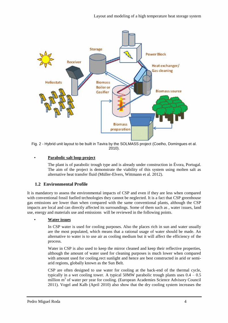
Layout and modeling of a high temperature heat storage system
Pedro Miguel Roda 5
investment costs due to specific operating and maintenance costs of the system the Solar
Tower Juumllich (STJ) is an example of a facility using this system
bull Land use
Land use is the total area occupied by all the structures that belong and are needed to keep
the plant working In a CSP technology the collectors field is the structure that will
require a bigger area usually CSP are built in arid places that will have clear skies And
like any other energy technology it will also bring some visual effects on the nearer
populations even when CSP one technology that makes a relatively efficient usage of the
land occupied when compared to other solar technologies (Tsoutsos Frantzeskaki et al
2005) Table 1 shows a comparison between energy conversion technologies and CSP It
is presented in relation to the energy generated annually by each plant (European
Academies Science Advisory Council 2011)
Table 1- Land use comparison between energy conversion technologies (European Academies Science Advisory Council 2011)
Land use [m2(MWh-1 y-1)]
Parabolic solar power Spain 11
Solar tower power Spain 17
Photovoltaic power plant Germany 56 (photovoltaic power can also be placed on rooftops which
corresponds zero land use)
Wind power lt5
Biomass plantation France 550
Open-cast mining (lignite) Germany 60
High-voltage power transmission line across Europe 04
bull Energy and materials use
If a life cycle assessment is made of a CSP technology it is immediately noticed that the
greenhouse gas emissions are much lower than in conventional fossil fuelled power plants
although there are still some emission associated with CSP Most of these emissions are
related to the really high material use of CSP such as steel pipes and mirrors and if
storage is implemented the salts used as storage system
CSP greenhouse effects can increase if fuel backup is used because this is the only
situation that fuel is used in CSP technology (European Academies Science Advisory
Council 2011) and excepting these cases no fuel is used in CSP plants
13 Socio-Economic impacts
As it is mentioned before the impacts of CSP are mostly local this is also true for socio economic
impacts CSP technology needs some employees with high know-how but also need cleaning teams
and maintenance so the local market can benefit with the project Also the construction materials
since they are ordinary construction materials such as steel or concrete can be purchased in local
providers A lot of CSP projects are built in smaller towns or isolated places the local population can
benefit of an increase demand of ordinary goods and services
CSP costs vary with technology but the solar fieldrsquos costs represent the biggest cost of the project
There will be operation and maintenance costs and also costs with personnel It is extremely difficult
to make a comparison between conventional fossil fuelled power plants and renewable energy power
plants A usual methodology to compare costs of electricity generation between such technologies is to
calculate the ldquolevelised electricity costrdquo (LEC) which relates average annual capital and operating
costs of the plant to the annual electricity production (European Academies Science Advisory Council
2011) Table 2 illustrates the costs of generating technologies in 2010 (European Academies Science
Advisory Council 2011)
Layout and modeling of a high temperature heat storage system
Pedro Miguel Roda 6
Table 2- Illustrative costs of generating technologies in 2010 (currency conversion 2010 $euro = 0755) (European Academies Science Advisory Council 2011)
Technology LEC
[eurockWhe-1]
Capacity
[MW]
EPC cost
[eurokWe-1] Cap factor
Fuel costs
[eurockWhe-1]
OampMfix
[eurokW-1 y-1]
OampMvar
[eurockWhe-1]
CSP 100 MW
no storage
(Arizona)
179 100 3542 028 0 48 0
Pulverised coal
650MW base-
load
69 650 2391 090 29 27 03
Pulverised coal
650MW base-
load
90 650 2391 057 29 27 03
Gas combined
cycle mid-load 61 540 738 040 32 11 03
Wind on-shore
100MW 85 100 1841 03 0 21 0
Wind off-shore
400MW 153 400 4511 04 0 40 0
Photovoltaic
150MW
(Arizona)
212 150 3590 022 0 13 0
Analysing Table 2 it is easy to notice that there is a long way for renewable energy resources to
become competitive in the energy market Although with so many incentives and with the aim of
governments to turn fossil fuelled economies into clean energy economies And with the aim of
private investors to reduce their companies carbon foot print it is expected that a cost reduction by
scaling up renewable energy projects and technology innovations will turn renewable energy
resources into a competitive option (European Academies Science Advisory Council 2011)
14 Reforming process
141 Hydrogen production and methane reforming
Hydrogen production it is a process that is already being studied for a long time Hydrogen production
is mostly made by converting a material with high contents of hydrogen (H2) such as gasoline
ammonia or methanol into hydrogen rich flow This hydrogen can be later used in recent
technologies like fuel cells s an energy carrier and as an important ldquoraw materialrdquo in chemical
industries and refineries
Theoretically the hydrogen produced all around the world nowadays is produced by the catalytic
reforming of methane technique Different reactions can take place in methane reforming and two of
them are (1) steam methane reforming (SMR) and (2) CO2 (or dry) methane reforming (DMR)
(Agrafiotis von Storch et al 2014)
molkJHOHCH 206 CO3H 224 (1)
molkJHCOCH 247 CO22H 224 (2)
Both reactions are endothermic which means that an heat source is needed so that the reactions can
take place (Agrafiotis Von Storch et al 2014) Currently the hydrogen produced from fossil fuels is
used as a chemical in industrial processes
The reforming process as mentioned above needs energy to occur If solar energy (or any other
renewable energy resource) is used the process becomes free of fossil fuels and in this case the
production of solar fuels is achieved The process takes place in a range of temperatures from 800 to
1000degC which also means that there are already CSP technologies that can fit in this range
Layout and modeling of a high temperature heat storage system
Pedro Miguel Roda 7
2 Thermal storage Independently of the energy production technology it is a great advantage if the energy is coming from
a versatile dispatchable technology This property enables the technology to provide energy (almost)
on demand It is a fact that solar is a non-dispatchable technology and this represents one of the major
challenges on solar technology
In CSP there is the option to integrate a thermal heat storage system that could maintain the plant
working during cloudy periods and if the thermal storage capacity is big enough during night periods
Currently a lot of the researchers effort is to improve this systems and find one that is feasible and do
not compromise the efficiency of the process and do not increase the cost of the whole plant into
extremely high values
This chapter gives an overview on the different types of thermal storage concepts classification and
materials and their properties
21 Thermal energy storage concepts
There are different concepts for thermal heat storage systems Two groups can be identified active
and passive systems And active storage systems can be independently identified as direct or indirect
This type of classification is independent of the systemrsquos storage material and physical storage (Gil
Medrano et al 2010)
The decision on which type of technology will be used in a certain application depends on operation
temperature boundary conditions and development of the technology
211 Active direct and indirect storage systems
An active direct storage system is a more difficult system to implement because in this system the
storage material is also the heat transfer fluid which means that is necessary to find a material that can
be a good heat transfer fluid and a good storage material decreasing the options that can fit in both
An indirect storage system usually makes use of two different materials one is the heat transfer fluid
and other one is the storage material and by pumping the heat transfer fluid through a heat exchanger it
will heat up the storage material that is also being pumped Usually this is a more complex system in
terms of infrastructures because tanks are needed (Gil Medrano et al 2010) A scheme of these
concepts can be seen in Fig 3
Fig 3 - Scheme of active direct (left) and active indirect (right) storage systems
212 Passive storage systems
In a passive storage system the heat transfer fluid will be pumped through another medium that will be
the storage material in this system the storage material is not being pumped and the heat transfer fluid
is just used to charge or discharge the storage system (Gil Medrano et al 2010) A scheme of this
storage concept can be seen in Fig 4
Layout and modeling of a high temperature heat storage system
Pedro Miguel Roda 8
Fig 4 - Scheme of a passive storage system
The most common storage systems applied until now are the indirect storage system and the passive
systems (or regenerators) On the next section there will be a detailed description about the storage
medium and physical storage
22 Storage Media
The storage system can have different storage media such as liquid solid or gaseous the system can
also make use of different physical phenomena to store energy by heating up a medium without phase
change making use of a phase change of a material at a certain temperature or by chemical reactions
that are completely reversible
On the following sections a detailed description on each storage media and some of their applications
is presented
221 Sensible Heat Storage
Sensible heat storage means that the energy will be stored in a material without its phase change It is
important to make a wise choice of material as well as an intensive study of its behavior under
operating conditions The material can be liquid solid or gaseous and it will store energy accordingly
with (3) (Hasnain 1998)
∆11987612 = 119898 int 119888119901(119879)119889119879
1198792
1198791
(3)
2211 Sensible heat storage materials
As it is mentioned above the storage material choice is a crucial point in heat storage systems The
material has to have desired properties for the application And even when different physical heat
storage will be presented the storage materials will have a lot of properties in common A list of
desired properties of storage materials to be implemented in a sensible heat storage system are
Layout and modeling of a high temperature heat storage system
Pedro Miguel Roda 9
presented below and categorized in thermo-physical-(A) chemical-(B) mechanical-(C) economic-
(D) and environmental (E) properties (Khare DellAmico et al 2013)
(A)
bull High energy density
bull High thermal conductivity
bull High heat capacity
bull High density
bull Long thermal cycling stability
(B)
bull Long thermal chemical stability with no chemical decomposition
bull Non-toxic
bull Non-explosive
bull Low corrosion potential or reactivity to heat transfer fluids
bull Compatible with materials of construction
(C)
bull Good mechanical stability
bull Low coefficient of thermal expansion
bull High fracture toughness
bull High compressive strength
(D)
bull Cheap and abundant materials
bull Low cost of manufacturing into suitable shapes
(E)
bull Low manufacturing energy requirement
bull Low CO2 foot print
After evaluating the properties requirements for a certain application a short list of materials should be
elaborated and the materials should be intensively studied Find if the material deteriorates under
operating conditions feasibility and thermal behavior For high temperature applications the most
promising materials are ceramics and metals (Khare DellAmico et al 2013)
2212 Sensible heat storage concepts
The two main concepts of sensible heat storage systems are solid and liquids which will be explained
in detail on the following points
bull Solids
Chose a solid material as a storage the storage material is usually a choice based on its low
cost When solids are used ordinarily concrete leakages phase changes freezing or
evaporation problems are not faced On the other hand solids durability degradation after
several cycles of use and their low thermal conductivity represent the biggest
disadvantages of this concept (Shukla 1981)
Layout and modeling of a high temperature heat storage system
Pedro Miguel Roda 10
bull Liquids
Liquids have the high thermal conductivity as their big advantage but for high
temperatures they have to be pressurized Freezing and boiling points are the biggest
challenges on sensible heat storage systems using liquids as storage material which also
makes it a more difficult storage material to store (Shukla 1981)
There are already few systems implemented under investigation or in test campaigns On the
following sections some examples of both concepts are presented
2213 Examples of sensible heat storage systems
bull Concrete
Concrete is a tempting option since it is a relatively cheap material it is widely use around
the world and it is abundant
The systems using concrete as storage material consist of concrete block that is crossed by
a tube matrix The heat transfer fluid flows through the tubes and heats up the concrete
block This concept has already been tested and concrete showed a great durability
performance Although the system requires a huge area to be installed and its low thermal
conductivity has to be improved which represent the biggest disadvantages of the system
Thermal stability of concrete was evaluated but only for temperature ranges of 400 -
500degC For this temperature ranges a concrete storage test module was built and tested in
The system was tested in a temperature range between 400 - 500degC in Stuttgart
Germany (Laing Bahl et al 2012) A system sizing determination for the parabolic
through solar thermal power plant of the ANDASOL-type was calculated and a 50000 m3
is required and has to be built in a modular approach (Laing Bahl et al 2012)
Some solutions for the poor thermal performance due to concretersquos low thermal
conductivity (range 12 ndash 145 W m-1
K-1
) were investigated and an improvement of
around 15 was achieved by adding structures with high thermal conductivity (Laing
Steinmann et al 2008)
bull 2 Tank molten Salt Indirect Storage
The two tank system is one of the most storage systems implemented This system uses
liquid as the storage media This heat storage system consists of 2 tanks one hot tank and
one cold tank During charging the salt from the cold tank is pumped through the heat
exchanger and is heated up by the heat transfer fluid and stored in the hot tank During the
discharging cycle the direction is reversed and the hot salt heats up the heat transfer fluid
and is stored in the cold tank If the heat transfer fluid is also used as storage material the
heat exchanger is not needed in the systems
This is system was successfully tested in the Solar Two project and its operating
temperatures are between 290-390degC using a molten salt mixture This system is always
limited by the molten salt allowable operating temperatures because the mixture cannot
freeze inside the tanks or pipes system it limits the lowest temperature And since
corrosivity increases with the temperature for molten salts tankrsquos materials have to be
chosen carefully And the mixturersquos thermal performance can be affected in higher
temperatures (Kolb 2011 Dunn Hearps et al 2012)
bull Steam accumulator
Steam accumulators systems are storage systems for short periods that solar radiation is
not available like cloudy periods since accumulators deliver the energy stored quickly
and its cost are proportional to the pressure vessel used in the system
Steam accumulators make use of the high water thermal conductivity property and since
water is not liquid above 100degC for CSP applications it has to be pressurized The system
Layout and modeling of a high temperature heat storage system
Pedro Miguel Roda 11
is charged by providing steam to the liquid medium of the steam accumulator that will
increase the liquid water temperature For discharging the pressure is lowered and steam
is generated A scheme of this system is presented in Fig 5
Fig 5 - Steam accumulator scheme (Laing 2008)
bull Packed bed (and regenerators)
In a packed bed system the heat transfer fluid flows through a container that is full with
small particles made of materials with high thermal conductivity Regenerators are
structures with high thermal conductivity and the heat transfer fluid flows through them
The regenerator concepts is a known system from the aluminum industry that is carried
out at temperatures around 1100degC usually using ceramics materials
This type of system is implemented in the STJ in Juumllich where is used as heat transfer
fluid and alumina is the storage material and its properties are shown in Table 3 The
storage and heat transfer fluid are in direct contact during chargingdischarging process
The air flows through small channels this structure is typically called honeycomb brick
(Zunft Haumlnel et al 2011) The system has already been tested under operating conditions
between asymp200- 630degC (in March 2010) and it has a good thermal performance delivering
air almost at constant temperature when discharging (Zunft Haumlnel et al 2011)
A pebble bed regenerator was investigated by Fraunhofer UMSICHT making use of
extremely small spherical materials (3 to 12 mm diameter) if alumina oxide pebbles are
used the system can reach high temperatures since the maximum operating temperature
for this material is 1800degC (Daschner Binder et al 2013)
Table 3 - Material characteristics
Honeycombs
Material Alumina porcelain (C130)
Specific heat capacity 088 kJ(kgK)
Thermal conductivity 21 W(mK)
222 Latent heat storage
Latent heat storage systems make use of the release of heat during a phase change of a material This
concept has the advantage that it can occur almost at a constant temperature The process should be
reversible so the material will not change its properties after several cycles It is also mandatory that
all the material can be converted to the previous phase completely (Hasnain 1998) In this system it is
even more crucial an accurate choose of material that can fit to the specific application
Layout and modeling of a high temperature heat storage system
Pedro Miguel Roda 12
2221 Material to be used as PCM
It is expectable that the most investigated phase transition would be the transitions that release more
energy although the early investigations began with the phase change solid-liquid that usually releases
less energy than the liquid-vapor transitions This is explained that a better container is needed and
also leaking problems are more likely to happen when leading with gases (Abhat 1983)
As it is mentioned above the material should match the specific operating temperature range almost
perfectly The properties of the material even that they are similar to the properties of the materials
used for sensible heat they should have some specific performance due to their phase change usage
The thermodynamic (A) kinetic (B) chemical (C) and economic (D) criteria used to evaluate PCM
materials are (Abhat 1983)
The phase change material (PCM) should possess
(A)
bull A melting point in the desired operating temperature range
bull High specific latent heat of fusion
bull High density which reduces the container (storage) volume
bull High specific heat capacity to provide for significant additional sensible heat storage
effects
bull Congruent melting the material should melt completely so that the liquid and solid phases
are identical in composition otherwise the difference in densities between solid and
liquid cause segregation resulting in changes in the chemical composition of the material
(Abhat 1983)
bull Small volume changes during phase transition so that a simple containment and heat
exchanger geometry can be used (Abhat 1983)
(B)
bull Little or no super cooling during freezing the melt should crystallize at its thermodynamic
freezing point This is achieved through a high rate of nucleation and growth rate of the
crystals (Abhat 1983)
(C)
bull Chemical stability
bull No chemical decomposition so that a high latent thermal energy storage system life is
assured (Abhat 1983)
bull Non-corrosiveness to construction materials
bull The material should be non-poisonous non-flammable and non-explosive
(D)
bull Available in large quantities
bull Inexpensive
In order to evaluate the properties of the material after several cycles under operating conditions the
melting and freezing characteristics of the material should be evaluated before Abhat (1983) suggests
Layout and modeling of a high temperature heat storage system
Pedro Miguel Roda 13
that two measurement techniques can evaluate these characteristics Differential Scanning Calorimetry
and thermal analysis
Table 4 gives a summary of phase change materials A more complete and detailed list of phase
change materials is presented in Caacuterdenas and Leoacuten (2013) work
Table 4 - Melting temperature for different compounds
Temperature range
[degC] Material
Transition
temperature [degC] Heat of fusion [kJkg]
0 -100
Water
Paraffin
Salt hydrate
0
20-60
30-50
335
140-280
170-270
100-400
AlCl3
LiNO3
Na2O2
192
250
360
280
370
314
400-800
50LiOH50LiF
KClO4
LiH
427
527
699
512
1253
2678
800-1500
LiF
NaF
MgF2
Si
868
993
1271
1415
932
750
936
1654
The storage capacity of a latent heat storage system in phase transition solid-liquid is given by (4)
(Portaspana 2011)
Tm
Ti
Tf
Tm
pmmp dTCmhadTCmQ (4)
2222 Latent heat storage systems
It is mentioned in the previous section that latent heat storage systems have the advantage that the
process of charging and discharging can be carried out in an almost isothermal condition making use
of the heat released or consumed by phase change Although most of the phase change materials have
low thermal conductivity In order to have an efficient latent storage system this property has been
investigated recently and a lot of investigators try to find a solution to improve it (Caacuterdenas and Leoacuten
2013)
A popular project that presented some solutions for the challenges in latent heat storage systems is the
DISTOR project (Steinmann and Tamme 2008) The solutions presented in the project are
bull Extended heat transfer area
This approach suggests that if the heat transfer fluidrsquos container area in contact with the
PCM is larger the phase change will occur faster because the distance for heat transfer
between the container and the solid PCM is reduced
bull Composite material with increased thermal conductivity
Materials with extremely high thermal conductivity are added to the PCM
Some applications using these solutions are presented on the following section
Layout and modeling of a high temperature heat storage system
Pedro Miguel Roda 14
2223 Examples of latent heat storage systems
bull Sandwich design
Typically latent heat storage systems consist of a tube (or container) where the heat
transfer fluid is flowing and this tube is in contact with the phase change material When
charging usually the phase change material is changing its phase from solid to liquid If
the thermal conductivity of the phase change material is low the process is much slower
and inefficient and what can occur is that part of the material is still solid by the end of the
charging period
The sandwich design consists in the addition of a structure in between of the phase
change material with high thermal conductivity These structures are added in parallel to
to each other and perpendicular to the tube containing the heat transfer fluid (Steinmann
and Tamme 2008)
Fig 6 shows the scheme of a storage unit of the sandwich concept Foils made of
exfoliated graphite are combined with PCM to form a sandwich structure
Fig 6- Schematic of the sandwich concept using graphite foil (Steinmann and Tamme 2008)
Cascaded PCMs
The latent heat storage systems as it is mentioned before make use of a phase change in a
material that occurs almost at constant temperature The performance of these systems
depends on the temperature difference between the PCM and the heat transfer fluid During
charging process the heat transfer fluid is transferring heat to the PCM that is changing its
phase although the heat transfer fluid will also decrease its own temperature Which means
that until the heat transfer fluid leaves the system on the outlet the process is less efficient on
the end part of the system (if we only consider along the x axis)
Some investigations suggest that if the difference between the PCM and the heat transfer fluid
is kept constant along the whole process the system has a much better performance What the
Layout and modeling of a high temperature heat storage system
Pedro Miguel Roda 15
investigations suggest is that a series of PCM is placed in series next to each other where the
phase change temperature is lowering from the left (inlet during charging) to the right (outlet
during charging) this temperature is constant along the whole process and a constant heat flux
is also achieved this approach is usually called cascaded PCM (Jegadheeswaran and Pohekar
2009) Fig 7 shows an example of a cascaded heat storage system
Fig 7 - Example of a cascaded latent heat storage system (Michels and Pitz-Paal 2007)
Experimental investigations with three PCMs sodium nitrate NANO3 a eutectic mixture of
potassium nitrate and potassium chloride KNO3KCl and potassium nitrate KNO3 were
carried out by (Michels and Pitz-Paal 2007)
Michels and Pitz-Paal (2007) work show that when this approach is used a bigger amount of
PCM changes its phase when compared with systems that only use a single PCM they
determined that when using the cascaded approach the PCM material that experiments a phase
change is around 92 during charging process and 67 during discharging process Even
when using a single PCM that the whole material experiences a phase change during charging
process during discharging process only 2 of the material experiences a phase change
Lithium carbonate Li2CO3 prototype
This prototype uses Lithium carbonate Li2CO3 as PCM material and makes uses of copper to
improve the thermal performance of the PCM Verdier Ferriegravere et al (2014) performed
numerical simulations that can be analyzed The system is in equilibrium ate the beginning
and is set on a uniform temperature of 700degC To charge the system a temperature of 900degC is
set as boundary condition on the bottom part of the structure To evaluate the discharging
process of the system a boundary condition of 100degC is set on the bottom of the structure and
before the discharging process begins a uniform temperature of 900degC is assumed for the
system The concept of the system analyzed is showed in Fig 8
Fig 8 - 3D representation of the concept (Verdier Ferriegravere et al 2014)
Layout and modeling of a high temperature heat storage system
Pedro Miguel Roda 16
The numerical results are shown in Fig 9
Fig 9 - Evolution of the PCM temperature during heating (left) and cooling (right) phase (Verdier
Ferriegravere et al 2014)
T1 T3 T5 and T7 are temperatures closer to the fin and T2 T3 T4 and T8 are located in the
center of the compartment
Fig 9 shows the results of the numerical investigations performed by Verdier Ferriegravere et al
(2014) Here a comparison with a system using only PCM without the copper fins was not
made So the only results that can be evaluated is that the system takes around 4h to be
completely charged and 25h to be completely discharged
More investigations and comparisons between traditional latent heat storage systems and system with
the integration of material with high thermal conductivity should be made to really determine its
advantages and influences on the system
223 Thermochemical heat storage
On thermochemical heat storage it is taken advantage of enthalpy but instead of a phase change like in
latent heat storage this system makes use of the completely reversible endothermic chemical
reactions The concept of this system is to absorb the excess heat in an endothermic reaction and store
the products on separate containers During discharging the products are combined exothermically and
the heat of reaction can be used
These systems are far behind in maturity when compared with sensible or latent heat storage systems
but they represent a promising solution due to their high energy density and by the possibility to store
energy at ambient temperature
Like the other systems presented above a proper choice of the materials should be evaluated on the
next section the material choice and properties are presented
2231 Properties of reactions considered for thermochemical energy
storage systems
On thermochemical the properties are related to compounds and reactions On this type of storage
systems the properties chased are even more peculiar and crucial
Necessary properties of the compounds to be used as thermochemical heat storage as told in
Portaspana (2011) work are
Reversibility
No side reactions or changes in reaction rate with the time should occur The reaction should
be completely reversible (Portaspana 2011)
Layout and modeling of a high temperature heat storage system
Pedro Miguel Roda 17
Reaction rates
Both forward and reverse reactions must be rapid enough to absorb all the available energy or
release it promptly The reaction rates must not decrease with cycling Such a decrease can be
observed if structural changes of the storage medium occur (Portaspana 2011)
Controllability
The reactions must be controllable because they have to be turned on and off when required
Controllability is achieved by product separation by controlling the temperature and pressure
or by catalysts (Portaspana 2011)
Ease of storage
The reaction products have to be easily separable prior to storage Reactions must not occur at
storage temperature (Portaspana 2011)
Safety
Toxicity inflammability and corrosiveness of the reaction products may pose unacceptable
safety hazards (Portaspana 2011)
Cost
Cost should be as low as possible which requires materials which are readily available
(Portaspana 2011)
On the following section will be presented some reactions considered for thermochemical heat storage
2232 Examples
Ammonia dissociation
When a thermochemical heat storage system is being implemented it will occur in a reactor
An important detail when evaluating promising reactions is if the process is already well-
known in other applications This is the case of ammonia dissociation reaction (5) the heat
recovering reaction is the well-known Haber Bosch process usually employed for fertilizer
production Ammonia dissociation has other advantages such as no side reactions occur and it
consists of no aggressive reactants for the environment On the other hand ammonia
dissociation has a relatively low enthalpy of reaction around 665 kJmol (Lovegrove Luzzi
et al 1999) Most of the studies on this reaction as a heat storage system have been carried out
by the Australian National University
223
2
3
2
1HNHNH
(5)
Reduction and oxidation reactions
This is a two-step concept that makes use of the principle of transition between the oxidized
and reduced form of an oxide of a metal that has multiple oxidation states (Agrafiotis Roeb et
al 2014)
On the first step an endothermic reaction (6) takes place with the supply of external heat the
reduced state of the oxide MeOox is obtained as a product (Agrafiotis Roeb et al 2014) The
general reaction is
)()( 2 gOMeOHMeO redox (6)
On the second step an exothermic reaction (7) takes place via an oxygen source If air is used
as the oxygen source the oxidation reaction is as the same structure as (Agrafiotis Roeb et al
2014)
Layout and modeling of a high temperature heat storage system
Pedro Miguel Roda 18
)()(2 HMeOgOMeO oxred (7)
Agrafiotis Roeb et al (2014) present the relevant reversible reactions considered for
thermochemical processes as scheme (8) for metal hydroxides scheme (9) for carbonates and
scheme (10) for oxides
reactmolkJHOHCaOHOHCa 100 )()( 22 (8)
reacmolkJHCOCaOHCaCO 167 )( 23 (9)
reacmolkJHOCoOHOCo 200
2
13)( 243
(10)
Heating cycles between 985 and 785degC were performed by Tescari Agrafiotis et al (2014) in
Co3O4 as well as Co3O4 ndash based binary powder metal oxide compositions under air They
showed on their work that the reactions are completely reversible Tescari Agrafiotis et al
(2014) investigated an hybrid system This hybrid system consists of coating a typical
honeycomb sensible heat storage system The investigation suggests that the system will have
a similar behavior to the plain powder thermochemical system and will improve the ceramic
honeycomb system by increasing the amount of energy stored by the system
Cobalt oxide powder was compressed and become a cobalt oxide pellet and was tested by
Karagiannakis Pagkoura et al (2014) Their work shows that the pellet can slightly improve
the performance of the chemical reaction The results for powder and pellet can be seen in Fig
10
Fig 10 - Comparison of thermochemical redox behavior of cobalt oxide in powder and pellet form
(Karagiannakis Pagkoura et al 2014)
In Fig 10 the red line represents the cobalt oxide pellet and the blue line represents the
powder And by analyzing the peaks it is possible to understand that it is possible to operate in
a wider range of temperatures and recover more heat from the reaction
Miguel Gonzalez-Aguilar et al (2014) are on the early investigations for a fluidized bed
system considering the manganese (III) redox reaction showed in (11)
3224332 OMn of 831 46 molkJHOOMnOMn (11)
Sulfur based thermal energy storage
This thermochemical storage concept consists on storing energy by producing elemental sulfur
for later burning To produce elemental sulfur on a thermochemical process three chemical
reactions take place (12) concentrated sulfuric acid is decomposed by heat into water sulfur
dioxide and oxygen (13) sulfur dioxide undergoes disproportionation in water into sulfuric
Layout and modeling of a high temperature heat storage system
Pedro Miguel Roda 19
acid and elemental sulfur (14) the sulfur generated is directed to storage andor to a sulfur
burner for combustion to generate heat The thermochemical cycle does not produce waste
effluent and does not emit greenhouse gas into the environment (Bunsen Wong 2013)
molkJHgSOgOgOHH 97 )(2)()(2(l)SO2H Decomp SO 222 4242 (12)
)((aq)SO2H)(3 O(l)2H ionDisproport 42222 lsSgSOSO (13)
molkJHgOlsSS 297 (g)SO)( )( Combustion 22 (14)
3 Mathematical model
31 Introduction
In this chapter the thermal interaction between the heat transfer fluid and the storage material of the
system is studied mathematically
The system studied is similar to the one installed in the STJ (Zunft Haumlnel et al 2011) using air as
heat transfer fluid and alumina as storage material
The model objective is to simulate a dynamic state of the thermal storage system during charge and
discharge process as well as to switch between these processes in a continuous simulation run This
ability of switching between charging and discharging conditions in one simulation is of crucial
importance in order to enable the complete simulation of the solar methane reforming plant where the
model will be integrated Determining the relation between the total volume of the storage system and
the number of hours that it can provide heat to operate the plant is also a goal of this work
The model discretizes the storage in a large number of interacting layers providing detailed
information about the temperature distribution within the storage Air flows through the honeycomb
bricks channels to transport the heat to or from the storage The convective heat transfer coefficient
between air and solid is sufficiently large which leads to a small temperature difference between air
and solid during charging or discharging of the system
The storage model presented in this work assumes an ideal storage which means that no heat losses
are taken into account during charging or discharging period During standstill period (when air is not
flowing through the channels) the temperature gradient will remain the same until the next charging or
discharging period starts again
The temperature dependent properties of air and the pressure loss by forced convection have been
considered in this model
The storage model is implemented in Aspen Custom Modelerreg with the appropriate syntax shown in
Appendix A - Aspen Custom Modeler Model Code
In order to reduce the computations time only a single channel of one honeycomb brick is simulated
The same conditions are assumed for each parallel channel so that all the channels will have a similar
behavior since no heat losses to environment are considered The energy stored by the system is then
the product of number of channels by the energy stored in only one channel
Layout and modeling of a high temperature heat storage system
Pedro Miguel Roda 20
311 Storage structure
As mentioned in the previous sections the system modeled is similar to the system installed in STJ
The system installed in STJ consists of a storage chamber made of honeycomb storage elements as
shown in Fig 11
The model will only consider the volume of material capable of storing energy which is the volume of
honeycomb bricks excluding the housing and insulation material The model does not consider any
degradation after a long operating period
311 Storage system general properties
The storage installed in STJ is a regenerator-type Air flows from the top to the bottom of the system
in direct contact with the alumina structure during charging period During discharging the air flow is
reversed
The system installed in STJ is a block with a volume of 120m3 and a height of 3m and operates
between 680 and 120degC with a nominal charge mass flow of 94 kgs Table 5 is a summary of the
storage specifications (Zunft Haumlnel et al 2011)
Table 5 - Storage specifications
Storage specifications
Temperature
range
680 ndash 120 degC
Charge mass
flow
94 kgs
Pressure loss lt1500 Pa
The storage material used is alumina porcelain (C130) and its thermophysical properties are shown in
Table 6 (Zunft Haumlnel et al 2011)
Table 6-Alumina porcelain (C130) properties
Honeycombs 60 x 60 channels
Brick dimensions 15 x 15 x 15 cm
Mass density 2700 kgm-3
Specific heat capacity 088kJ(kg-1K-1)
Themal conductivity 21 W(m-1K-1)
Heating surface 1180 m2m-3
Fig 11 - Honeycomb brick
Layout and modeling of a high temperature heat storage system
Pedro Miguel Roda 21
311 Honeycomb storage principle
The principle of the honeycomb ceramic is identical to other sensible heat storage During the
charging period the hot air flows through the systems micro-channels and releases heat increasing the
material temperature During the discharging period the flow direction is reversed and then cold air
flows through the systems micro channels and absorbs the heat stored in the material resulting in an
increase of the air temperature
As Luo Wang et al (2013) showed the honeycomb ceramic have an excellent heat transfer
characteristic resulting from the larger heat exchange area and fine flow behavior meaning relatively
small pressure drop resulting from the flow-through channels
32 Physical model
Fig 12 shows the physical model which consists of a quadrangular channel with length L and opening
s During the charging process heated air flows through the channel from top to bottom of the
channel During the discharging process the air flow is reversed and cold air is pumped from the
bottom to the top of the channel
The channel is discretized in a certain amount of points between 0 and L with the same spacing
between each other The spacing between each point will return more or less accurate results for a
smaller and larger spacing respectively The spacing will also influence the simulation time so a
optimal situation should be determined where a not so time consuming simulation can be carried out
with reasonable accurate results
Fig 12 - Physical model of the storage system
A temperature gradient is achieved during both processes and the system is considered completely
charged when the air temperature in the outlet exceeds the defined minimum temperature that should
usually be defined according to the outlet temperature of the process ie heat exchangers that the heat
is used in In opposite the system is considered completely discharged when the air outlet temperature
during discharge decreases below the required higher temperature level A representative scheme of
the thermal gradient in the system is shown in Fig 13
Layout and modeling of a high temperature heat storage system
Pedro Miguel Roda 22
Fig 13 - Representative thermal gradient in the storage system
33 Governing Equations
The storage system modeled is a regenerator-type heat storage A regenerator is a type of heat
exchanger in which the hot and cold-fluids occupy the same physical space but at different times
Regenerators necessarily operate in a transient mode The temperatures throughout the system depend
upon time as well as on position Partial differential equations are needed to describe the time and
spatial dependence of the temperature of the solid and the fluid These equations can be identified
using energy balances on the fluid and solid (Nellis and Klein)
The energy equations used to describe the model follow the descriptions and assumptions listed below
Ideal behavior of the system the amount of energy recovered is the same as the amount
stored
The fluid flow inside the storage is vertical from top to bottom during charging and from
bottom to top during discharging
The fluid thermophysical properties are temperature and pressure dependent
The solid thermophysical are temperature independent
There is no heat generation or dissipation inside the storage
The system is well insulated and there are no losses to the ambient
Pressure drop along the channel is considered
The system is one dimensional only temperature gradients along the x axis
The energy equation for the fluid (15) is written as
119899119886119894119903 sdot 119888119901119886119894119903 sdot (
120597119879119886119894119903
120597119909) + 120588119886119894119903 sdot 119888119901119886119894119903 sdot 119860119888119904119886119894119903 sdot (
120597119879119886119894119903
120597119905) = 4 sdot 120572 sdot 119904 sdot (119879119886119894119903 minus 119879119904119900119897)
(15)
The first term on the left side of the equation corresponds to the enthalpy associated with the fluid
flow The second term on the left side of the equation corresponds to the rate of change of enthalpy
The term on the right side of the equation corresponds to the heat exchange by convection between the
solid and the fluid The conduction in the fluid can be neglected due to the small value of air
conductivity
The energy equation for the solid (16) is written as
Layout and modeling of a high temperature heat storage system
Pedro Miguel Roda 23
120588119904119900119897 sdot 119888119901119904119900119897 sdot 119860119888119904119904119900119897 sdot (
120597119879119904119900119897
120597119905) = 119860119888119904119904119900119897 sdot 119896119904119900119897 sdot (
1205972119879119904119900119897
1205971199092 ) + 4 sdot 120572 sdot 119904 sdot (119879119886119894119903 minus 119879119904119900119897) (16)
The term on the left side of the equation corresponds to the change of enthalpy of the solid The first
term on the right side of the equation corresponds to the heat transferred by conduction in the solid
along the x axis The second term on the right side corresponds to the heat transferred by convection
between the particles and the fluid
It is necessary to evaluate the convective heat transfer coefficient α to determine the heat transferred
by convection The convective heat transfer coefficient is affected by the state of the flow and the
shape of the duct and can be determined by (17) using the appropriate Nusselt correlation The heat
transfer convective coefficient is determined locally by the model
120572 =
119873119906 sdot 120582119886119894119903
119904
(17)
In order to use the appropriate correlations an evaluation of the flow state is needed this evaluation is
determined by the Reynolds number A flow is laminar if Re le 2400 and turbulent if Re ge 4000 in
between the flow is in a phase called transition (Yunus and Cimbala 2006) In the presented model the
Reynolds number range is from asymp7 ndash 12 meaning that the flow is in laminar phase The appropriate
Nusselt correlation is a correlation that gives the Nusselt number for a fully developed laminar flow
transferring heat to four walls in a quadrangular duct (18) (Shah and London 1978) which depends on
the side length of the duct entry cross section
119873119906 = 8235 [1 minus 20421 sdot 119886 + 30853 sdot 1198862 minus 24765 sdot 1198863 + 10578 sdot 1198864
minus 01861 sdot 1198865]
with 119886 =119888
119889
(18)
119886 represents the relation between the side length of the duct entry cross section and it is equal to one
for quadrangular ducts
331 Boundary and initial conditions
The temperature in the fluid and solid can be determined by (15) and (16) respectively The solution
of the temperatures depends on the physical conditions existing at the boundaries of the system An
initial condition is also needed since the system is also time dependent
The boundary condition to solve the fluid equation (15) is
The air inlet temperature is constant for all time
119879(0 119905) = 119879119886119894119903119894119899 (19)
The boundary conditions to solve the solid equation (16) are
In the first layer of the solid (since there is no previous layer) the conduction is only to the
next layer so the second derivative term becomes a first order derivative term
120588119904119900119897 sdot 119888119901119904119900119897 sdot 119860119888119904119904119900119897 sdot (
120597119879119904119900119897
120597119905) = 119860119888119904119904119900119897 sdot 119896119904119900119897 sdot (
120597119879119904119900119897
120597119909) + 4 sdot 120572 sdot 119904 sdot (119879119886119894119903 minus 119879119904119900119897)
(20)
In last layer of the solid (since there is no next layer) the conduction is only form the previous
layer so the second derivative term becomes a first order derivative term
120588119904119900119897 sdot 119888119901119904119900119897 sdot 119860119888119904119904119900119897 sdot (
120597119879119904119900119897
120597119905) = 119860119888119904119904119900119897 sdot 119896119904119900119897 sdot (
120597119879119904119900119897
120597119909) + 4 sdot 120572 sdot 119904 sdot (119879119886119894119903 minus 119879119904119900119897)
(21)
Layout and modeling of a high temperature heat storage system
Pedro Miguel Roda 24
The initial conditions at the beginning of the simulation are defined by the solid temperature
The system is in equilibrium and the fluid temperature inside the channel is equal to the solid
temperature
119879119886119894119903(119909 0) = 119879119904119900119897(119909 0) (22)
331 Pressure drop
Pressure drop is a quantity of interest since it is directly related to the power requirements of the fan or
pump to maintain flow which will be further considered when the model is implemented in the solar
methane reforming plant model
The pressure drop inside the channel is considered and was determined by (23) from Yunus and
Cimbala (2006)
∆119901 = 119891 sdot
119871
119863sdot
120588119886119894119903 sdot 1198811198861198941199032
2+ 120588119886119894119903 sdot 119892 sdot 119871
(23)
119891 is the Darcy friction factor and it is defined as (24) for fully developed laminar flow in a
quadrangular duct
119891 =
5692
119877119890 119877119890 =
119881119863
120584 119886119899119889 119877119890 le 2300
(24)
331 Energy balance
In order to make sure that the energy gain by the wall during charging process or the energy loss by
the wall during discharging process is the same as the air enthalpy change and make sure that the
model does not violate the first principle of thermodynamics (conservation of energy) two monitoring
variables were created and their values compared
These two variables are the solid enthalpy change determined by (25) and the air enthalpy change
(26)
119876119904119905119908119886119897119897 = 120588119904119900119897 sdot 119888119901119904119900119897 sdot 119860119888119904119904119900119897 sdot 119871 sdot (
120597119879119904119900119897
120597119905)
(25)
119876119886119894119903 = 119899119886119894119903 sdot [ℎ119886119894119903(119871) minus ℎ119886119894119903 (0)] (26)
34 Model Validation
Is necessary to check the model performance with already existing validated models or compare the
model with experimental data In order to compare the model with experimental data it is necessary to
recreate the model as much close to the real system
To validate this model experimental data and previous works from the system installed in STJ are
available (Zunft Haumlnel et al 2011 Kronhardt Alexopoulos et al 2014) To validate the model the
same properties from the system installed in the STJ are implemented in the model
A comparison between the model implemented in Aspen Custom Modeler and a model built in
Comsol Multiphysicsreg will also be shown in this chapter
341 Comparison with experimental data
A test campaign was performed by Zunft Haumlnel et al (2011) in March 2011 These experiments had
the goal to evaluate the storage performance and the validation of existing simulations and design
tools
Layout and modeling of a high temperature heat storage system
Pedro Miguel Roda 25
The experiments include charging period standstill and discharging performance of the storage
system Different inlet air temperatures and different inlet mass flows were tested and measured in the
test campaign The experimental data is not published in detail
The measured data was difficult to interpret and due to lack of information regarding the
thermocouples location it was not possible to achieve the correct interpretation of the measured data
and it was not also possible to establish a comparison between the model presented in this work and
the test campaign performed by Zunft Haumlnel et al (2011)
341 Comparison with previous validated models
The model presented by Hirsch IRT et al (2012) was validated using measured data from the system
installed in STJ The test boundaries as mass flow inlet temperature and inlet pressure are the
nominal solar tower process values showed in Table 5 The initial temperature gradient inside the
system presented by Hirsch IRT et al (2012) was determined by interpolation of the real temperature
of the storage (this initial gradient is not the discharged gradient it is just the reference point before
one hour charging period) Under these conditions this model is appropriate for validation of the
model created in this work
The comparison between the initial gradient in our model and the model by Hirsch IRT et al (2012) is
shown in Fig 14 The results show a good agreement
Fig 14-Initial gradient comparison between aspen model and (Hirsch IRT et al 2012) model
Horizontal axis is normalized
Another comparison is shown in Fig 15 this comparison is the systems profile temperature after one
hour charging Once again the presented model and the model presented by Hirsch IRT et al (2012)
show a good agreement The deviations can be due that in our model a constant inlet mass flow and
inlet temperature is assumed for the whole hour leading to no oscillations Also the difference in the
initial gradient leads to higher deviations between the two models It is expected that when the system
reaches a periodic steady state operating conditions the deviations are reduced
0
100
200
300
400
500
600
700
800
0 011 022 033 044 055 066 077 088 099
Tem
per
ract
ure
[degC
]
System height (normalized)
TAMM
Hirsch IRT et al (2012)
Layout and modeling of a high temperature heat storage system
Pedro Miguel Roda 26
Fig 15 - After one hour charging gradient comparison between Aspen model and (Hirsch IRT et al
2012) model Horizontal axis is normalized
341 Comparison with a Comsol Multiphysicsreg model
The model presented in this work simulates the behavior of one channel of the whole system A
channel of the whole system is a certain number or honeycomb bricks disposed in series on top of each
other until it reaches 3 meter high In our model to achieve the 3 meter height 20 models are connected
in series since every honeycomb brick has 15cm length as shown in Table 6
Aspen Custom Modelerreg is a powerful tool and enables to perform complex calculations and
simulations using a simple syntax and in short period of time Comsol Multiphysicsreg model is also a
powerful tool and also enables the creation of a 3D picture of the system In order to get a better
understanding of the system a simple Comsol Multiphysicsreg model was created
Comsol Multiphysicsreg model
The comsol model consists of a honeycomb channel The alumina properties applied are the same
shown in Table 6 and the air themophysical properties are temperature dependent
The boundary conditions applied in the Comsol model are
Constant inlet temperature of 680ordmC
Adiabatic outer walls of the channel
Constant inlet pressure
Outlet velocity asymp006 ms
The system is in an equilibrium state of 150ordmC in the beginning The system is evaluated after one hour
under these conditions and results are presented in Fig 16
0
100
200
300
400
500
600
700
800
0 011 022 033 044 055 066 077 088 099
Tem
per
ract
ure
[degC
]
System height (normalized)
TAMM
Hirsch IRT et al (2012)
Layout and modeling of a high temperature heat storage system
Pedro Miguel Roda 27
Fig 16 - Comsol results after one hour simulation
When this model is compared with the model created in Aspen that need to be connected in series the
results shown a good agreement with slight deviations The results curves are shown in Fig 17 In Fig
17 Tcomsol corresponds to the Comsol model data TAMM corresponds to the model created in
Aspen where several models are connected in series and TALCM corresponds to the model created in
aspen where a single long channel is simulated
Fig 17 - Comparison with comsol model
341 Comparison between Aspen Models
The model presented in this work shows a good agreement with validated models using measured
data But in order to implement our model in the complete solar methane reforming process model this
connection of blocks is extremely difficult to handle when a transient simulation is carried out due to
the fact that the charging outlet becomes the inlet during discharging of the system In order to
simplify this issue a single model of 3 meter height was created The main difference between a model
of 3m length and 20 models of 15cm length connected in series is that in the 3m length single model
thermal conduction between 2 consecutive bricks occurs
0
100
200
300
400
500
600
700
0 002 004 006 008 01 012 014
Tcomsol
TAMM
TALCM
Layout and modeling of a high temperature heat storage system
Pedro Miguel Roda 28
In order to make sure that thermal conduction between consecutive bricks will not lead to inaccurate
results the two aspen models are compared The curve of the first 15cm of the long channel aspen
model (represents the first brick) is also plotted in Fig 17 In the end of the curve a slight deviation
from the Comsol model and the aspen multiple bricks model can be noticed
Although if the complete systems are compared they show a good agreement here for simplification a
Comsol model is not considered
Regarding the conduction in a long channel can lead to high deviations in low dimensions as shown in
Fig 17 but when compared to the complete system these deviations are negligible as shown in Fig 18
where the series connected model and the single long model in Aspen are compared In Fig 18 the
curves cannot even be distinguished due to superposition
Fig 18 - Comparison between the two different Aspen models
35 Validation discussion
The model created is validated with the previous shown data comparison In order to reduce the
simulation time and the complexity of the system a model of a long single brick will be used to
simulate the system in operation and implemented in the complete solar methane reforming process
model Although this assumption is not completely accurate the deviation from accurate modelling is
small as the validation shows
In the next section a sizing of the system to be implemented will be shown since the solar methane
reforming plant characteristics are different from the STJ
4 System sizing
41 Introduction
In this section a relation between the total volume of the storage material and the solar methane
reforming plant operating hours is presented
As shown in Fig 19 the air is heated up in the solar receiver and pumped to the reformer The solar
methane reforming is designed to operate under constant conditions which means that the air mass
flow and temperature reaching the reformer should be constant during operation The heat storage
system is implemented in parallel to the reformer and the exceeding air during solar radiation period
is used to charge the heat storage system
0
100
200
300
400
500
600
700
800
0 05 1 15 2 25 3
TAMM
TALCM
Layout and modeling of a high temperature heat storage system
Pedro Miguel Roda 29
The charging mass flow to the heat storage system is adjusted enabling a constant air mass flow
delivered to the reformer at a constant temperature of 900 degC
Fig 19 - Solar methane reforming plant with storage scheme
42 Mass flow variation
The air mass flow available at 900 degC depends on the incident solar radiation at a certain time If the
intercept radiation is lower than 15 MWh no air mass flow is available at the desired temperature and
525 MWh is the maximum intercept radiation available
The air mass flow available to the storage system can be determined by (27) The total air mass flow
available varies with the time due to the solar radiation and the air mass flow to the reforming process
is constant
119886119894119903 119905119900 119904119905119900119903119886119892119890 = 119886119894119903 119905119900119905119886119897 minus 119886119894119903 119905119900 119903119890119891119900119903119898119890119903 (27)
Data for the intercept radiation for each hour of the year and the respective air mass flow available for
one channel of the system is evaluated and the first 58 hours correspondences are shown in Appendix
B
43 Energy available
The energy available for storage will be the enthalpy variation of the correspondent air mass flow
available for the storage system during that hour
The outlet temperature of the air after the reforming process is 368 degC and this also corresponds to the
outlet temperature of the heat storage system during charging period The energy available will be the
enthalpy variation of the air from 900 to 368 degC and it is determined by (28)
119905119900119904119905119900119903119886119892119890 = 119886119894119903 119905119900 119904119905119900119903119886119892119890 sdot [ℎ119886119894119903900 minus ℎ119886119894119903368] (28)
Layout and modeling of a high temperature heat storage system
Pedro Miguel Roda 30
A balance for each hour of the year is done (29) During charging period the energy stored is summed
and subtracted if a discharging period is taking place With this energy approach a maximum energy
stored in the system is determined
119876119878119905119900119903119886119892119890(119905 + Δ119905) = 119876119878119905119900119903119886119892119890(119905) + 119905119900119904119905119900119903119886119892119890 sdot Δt (29)
44 Operating hours
The operating hours will vary with the air mass flow designing point of the solar methane reforming
plant
If the air mass flow is set to a low value a higher air mass flow is available to store energy in the
storage system This will enable the solar methane reforming to operate for more hours and the plant
size decreases for a fixed product output when the operating hours are increased In an extreme
scenario the solar methane reforming plant could operate the 8760 hours of one year Although that
the plant could operate the whole year this is not the optimum scenario since the storage volume
required would become huge
45 System volume and shape
The volume of the storage material needed will vary with the operating hours A bigger volume is
needed for more operating hours and a smaller volume is needed for less operating hours
The shape will affect mainly the pressure drop of the system which increases with the length of the
system
Knowing the maximum energy to be stored in the system (determined on the previous point) the
material mass density the material heat capacity and the temperature difference that the system will
operate (in the solar methane reforming plant the temperature range is 900 ndash 368 degC) the storage
material volume needed can be determined by (30)
119881119904119905119900119903119886119892119890 =
119876119905119900119904119905119900119903119886119892119890119898119886119909
120588119904119900119897 sdot 119888119901119904119900119897 sdot ∆119879
(30)
46 System design
With all the information presented in the previous points it is possible to establish a relation between
the operating hours of the solar methane reforming plant and the volume of the storage material This
relation is shown in Fig 20 The maximum of the storage material needed is reached if the plant is
operated continuously for the whole year But this relation is not linear and if the plant is operated for
around 80 of the time the storage material volume needed decreases to around 5 of the maximum
volume needed to operate 100 of the time
Layout and modeling of a high temperature heat storage system
Pedro Miguel Roda 31
Fig 20 - Relation between operating hours of the plant and storage material volume needed Vertical
axis is normalised
The volume needed plotted in Fig 20 does not include housing and insulation material Part of the
material is not heated up (during charging period) or cooled down (during discharging period) because
the temperatures of the outlet cannot exceed the design parameters extra volume should be considered
when the system is implemented in the solar methane reforming plant
461 Reference case
After evaluating the previous results a reference case to simulate the performance of the system should
be set The chosen case is the point immediately before the volume rises exponentially In this case the
plant does not operate for a low number of hours and the system is kept as small as possible The
reference case parameters are shown in Table 7
Table 7 - Reference case parameters
Reference case parameters
Material mass density 2700 [kgm-3]
Material heat capacity 088 [kJ(kg-1K-1)]
Temperature difference 532 [K]
Maximum energy Stored 889 [GJ]
Storage material volume needed 7035 [m3]
Dimensions asymp89times89times89 m
Not operating hours 1785 [h]
When this approach is made it is necessary that the complete volume of the storage material changes
its temperature (form 368 to 900 degC in our application) and that it is no possible since the outlet
temperature of the system cannot rise above the set parameters It is necessary to increase the length of
the system in order to keep the outlet temperature inside its boundaries values
462 Charged and discharged gradients regarding extra length
The extra length needed to the system is determined by running a simulation under an ldquoenergy storedrdquo
condition This condition stops the simulation when the maximum energy stored in the system is
0
01
02
03
04
05
06
07
08
09
1
0 20 40 60 80 100
Vo
lum
e
Operating time
StorageMaterialvolumeneeded
Layout and modeling of a high temperature heat storage system
Pedro Miguel Roda 32
achieved during charging period (to the maximum energy stored value it is summed the value of the
energy stored in the system when it is fully discharged since this energy will not be recovered from
the system in order to guarantee that during discharging period the outlet temperature will not come
below the temperature needed in the process) The simulation is run with a much higher length than
the determined in the reference case When this charged state is achieved the system profile
temperature is evaluated and the outlet is set where the material did not experience any temperature
change This guarantees that when the fully charged condition is achieved the outlet temperature does
not exceed the minimum temperature of the process
After the simulation the total height of the system is determined The dimensions of the system are
showm in
Table 8 - System final dimensions
Reference case parameters
Cross section asymp89times89 m
Height asymp35m
Total volume asymp2772 [m3]
When the system is discharged the outlet temperature of the system cannot go below 900degC In Fig 21
is shown the discharged gradient of the system for the reference case regarding the extra length
needed to fulfill the required outlet temperature
Fig 21 - Reference case discharged temperature gradient considering extra length
When the system is completely charged the outlet temperature of the system cannot rise above 368degC
In Fig 22 is shown the charged gradient of the system for the reference case The outlet during
discharged is located on the left of the x axis (the flow is reversed when charging or discharging)
300
400
500
600
700
800
900
1000
0 5 10 15 20 25 30 35 40
Tem
per
atu
re [
degC]
Systems height [m]
Discharged
Layout and modeling of a high temperature heat storage system
Pedro Miguel Roda 33
Fig 22 - Reference case charged system temperature gradient considering extra length
47 Reference case results
A simulation for the whole year will be carried out for the reference case system An energy balance in
the storage system was determined using an excel sheet and the first 8 hours of this energy balance are
shown in Table 9 When the air to storage is a negative number means that the system is in discharging
period The values presented in Table 9 are results for the whole system
The simulations results and the predicted values show a good agreement with a slight deviation that
can be due to calculations approximation
Table 9 - Simulations results for the first 8 hours of the whole year
Hour Intercepted
Radiation
[MWh]
Air flow to
storage
[kmolh-1]
Energy to storage
[kJh-1]
Energy
accumulated in
the storage [kJ]
Simulation
energy
accumulated
results [kJ]
Error
1 3298 1665099758 2860384958 2860384958 285705133 012
2 4955 475274243 8164479573 1102486453 1101208254 012
3 525 5288722731 9085211188 2011007572 2008675251 012
4 525 5288722731 9085211188 2919528691 2916143713 012
5 525 5288722731 9085211188 382804981 3823613101 012
6 525 5288722731 9085211188 4736570929 4731083209 012
7 41 3216387444 5525258305 5289096759 528296684 012
8 3086 1299706711 2232695974 5512366356 5505977262 012
9 0 29927223 -5028518322 5009514524 5003701682 012
5 Conclusions Energy storage will play a major role in the future of the solar technologies when an energy storage
system is available the utilization of these technologies will increase and will allow solar power to be
produced on demand Energy storage will allow a solar power plant to keep producing energy during
cloudy periods or night period when it is needed the most And will increase the capacity factor of the
plants without fossil fuel backup
300
400
500
600
700
800
900
1000
0 5 10 15 20 25 30 35 40
Tem
per
atu
re [
degC]
Systems height [m]
Charged
Layout and modeling of a high temperature heat storage system
Pedro Miguel Roda 34
The main objective of this work was to model a high temperature heat storage system and predict its
layout in order to overcome the intermittence of the sun as the energy source and to enable the
operation of the plant under constant conditions The type of system chosen to model was a sensible
heat storage system due to the huge amount of information available about these systems
The state of the art in thermal heat storage system is the two tank technology Although that
technology did not fit to the reforming process due to the temperature boundaries related to the two
tanks system
The model was validated using data of previous works that modelled the same system A simulation
for the whole year will be carried out and for the first period of the simulation the results of the
system performance show an excellent agreement with the predicted values The model can be easily
adapted to other applications that want to make use of a sensible heat storage system since the inputs
and dimensions can be easily changed
One major limitation of the model is the neglecting of thermal losses to the environment even if those
losses play a minor role in the system this losses can become an optimization work of the model in a
near future Also the degradation of the material after a long operating period should also be evaluated
in the future since these degradation can lead to thermophysical properties variation of the material
An optimization of the model that can be carried out in the future is the determination of the housing
and insulation material needed to install a complete system
One of the main disadvantages of this system is the huge amount of area required to install it
Investigations in this field should be carried out in the future in order to reduce the volume of the
system
The major advantages of the system are its reliability and the fact that these system are close to other
applications in industry which makes it an already known technology
6 References
Abhat A (1983) Low temperature latent heat thermal energy storage heat storage materials Solar
Energy 30(4) 313-332
Agrafiotis C et al (2014) Exploitation of thermochemical cycles based on solid oxide redox
systems for thermochemical storage of solar heat Part 1 Testing of cobalt oxide-based powders
Solar Energy 102 189-211
Agrafiotis C et al (2014) Solar thermal reforming of methane feedstocks for hydrogen and syngas
productionmdashA review Renewable and Sustainable Energy Reviews 29 656-682
Agrafiotis C et al (2014) Solar thermal reforming of methane feedstocks for hydrogen and syngas
production - A review Renewable and Sustainable Energy Reviews 29 656-682
Bunsen Wong L B Robert Buckingham Dennis Thomey Martin Roeb and Christian sattler (2013)
Sulfur based thermochemical energy storage for concentrated solar power SolarPACES2013
Conference
Caacuterdenas B and N Leoacuten (2013) High temperature latent heat thermal energy storage Phase change
materials design considerations and performance enhancement techniques Renewable and
Sustainable Energy Reviews 27(0) 724-737
Layout and modeling of a high temperature heat storage system
Pedro Miguel Roda 35
Coelho B et al (2010) Solmass projectndashsolar biomass dual hybrid 4 MW CRS pilot plant
SolarPACES Symposium Perpignan
Daschner R et al (2013) Pebble bed regenerator and storage system for high temperature use
Applied Energy 109 394-401
Dunn R I et al (2012) Molten-salt power towers newly commercial concentrating solar storage
Proceedings of the IEEE 100(2) 504-515
European Academies Science Advisory Council (2011) Concentrating Solar Power Its Potential
Contribution to a Sustainable Energy Future EASAC Policy Report 16 EASAC
Gil A et al (2010) State of the art on high temperature thermal energy storage for power
generation Part 1mdashConcepts materials and modellization Renewable and Sustainable Energy
Reviews 14(1) 31-55
Hasnain S (1998) Review on sustainable thermal energy storage technologies Part I heat storage
materials and techniques Energy Conversion and Management 39(11) 1127-1138
Hirsch T et al (2012) DLR Institute for Solar Research (DLR)
Jegadheeswaran S and S D Pohekar (2009) Performance enhancement in latent heat thermal
storage system a review Renewable and Sustainable Energy Reviews 13(9) 2225-2244
Karagiannakis G et al (2014) Monolithic Ceramic Redox Materials for Thermochemical Heat
Storage Applications in CSP Plants Energy Procedia 49 820-829
Khare S et al (2013) Selection of materials for high temperature sensible energy storage Solar
Energy Materials and Solar Cells 115 114-122
Kolb G J (2011) Evaluation of annual performance of 2-tank and thermocline thermal storage
systems for trough plants Journal of Solar Energy Engineering 133(3) 031023
Kronhardt V et al (2014) High-Temperature Thermal Storage System for Solar Tower Power
Plants with Open-Volumetric Air Receiver Simulation and Energy Balancing of a Discretized Model
Energy Procedia 49 870-877
Laing D (2008) Solar thermal energy storage technologies Energy Forum 10000 Solar Gigawatts
23 April 2008
Laing D et al (2012) High-temperature solid-media thermal energy storage for solar thermal power
plants Proceedings of the IEEE 100(2) 516-524
Laing D et al (2008) Solid media thermal storage development and analysis of modular storage
operation concepts for parabolic trough power plants Journal of Solar Energy Engineering 130(1)
011006
Layout and modeling of a high temperature heat storage system
Pedro Miguel Roda 36
Lovegrove K et al (1999) A solar-driven ammonia-based thermochemical energy storage system
Solar Energy 67(4) 309-316
Luo Z et al (2013) Simulation and Experimental Study on Long Term Sensible Thermal Energy
Storage in Solar Thermal System SolarPACES2013
Michels H and R Pitz-Paal (2007) Cascaded latent heat storage for parabolic trough solar power
plants Solar Energy 81(6) 829-837
Miguel S et al (2014) 100-Wh Multi-purpose Particle Reactor for Thermochemical Heat Storage
in Concentrating Solar Power Plants Energy Procedia 49 676-683
Muumlller-Elvers C et al (2012) Design and Construction of Molten Salt Parabolic Trough HPS
Project in Eacutevora Portugal Proc SolarPACES
Muumlller-Steinhagen H and F Trieb (2004) Concentrating solar power A review of the technology
Ingenia Inform QR Acad Eng 18 43-50
Nagl S et al (2011) The economic value of storage in renewable power systems-the case of thermal
energy storage in concentrating solar plants EWI Working Paper
Nellis G and S Klein Heat Transfer Cambridge University Press
Pitz‐Paal R et al (2013) Solar Thermal Power Production Transition to Renewable Energy
Systems 307-338
Portaspana J C (2011) MASTER THESIS High temperature thermal energy storage systems based
on latent and thermo-chemical heat storage Universitaumlt Wien
Shah R K and A L London (1978) Laminar flow forced convection in ducts a source book for
compact heat exchanger analytical data Academic press
Shukla K (1981) Thermal energy storage for solar power generation state of the art Heat Transfer
Engineering 3(2) 62-72
Steinmann W-D and R Tamme (2008) Latent heat storage for solar steam systems Journal of
Solar Energy Engineering 130(1) 011004
Storch H V et al (2014) Investigation of Process Efficiency of an Indirectly Heated Solar
Reformer in M Eden JD Siirola GP Towler (Eds) International Conference on Foundations of
Computer Aided Process Design WAUSA Elsevier
Tescari S et al (2014) Thermochemical Solar Energy Storage Via Redox Oxides Materials and
ReactorHeat Exchanger Concepts Energy Procedia 49 1034-1043
Trieb F et al (2014) Concentrating solar power in a sustainable future electricity mix
Sustainability Science 9(1) 47-60
Layout and modeling of a high temperature heat storage system
Pedro Miguel Roda 37
Tsoutsos T et al (2005) Environmental impacts from the solar energy technologies Energy Policy
33(3) 289-296
Verdier D et al (2014) Experimentation of a High Temperature Thermal Energy Storage Prototype
Using Phase Change Materials for the Thermal Protection of a Pressurized Air Solar Receiver
Energy Procedia 49 1044-1053
Vogel W and H Kalb (April 2010) Large-Scale Solar Thermal Power Technologies Costs and
Development
Yang J et al (2013) Numerical analysis on the thermal behavior of high temperature latent heat
thermal energy storage system Solar Energy 98 543-552
Yunus A C and J M Cimbala (2006) Fluid mechanics fundamentals and applications
International Edition McGraw Hill Publication 185-201
Zunft S et al (2011) Juumllich Solar Power TowermdashExperimental Evaluation of the Storage
Subsystem and Performance Calculation Journal of Solar Energy Engineering 133(3) 031019
Layout and modeling of a high temperature heat storage system
Pedro Miguel Roda 38
Appendix A - Aspen Custom Modeler Model Code
Layout and modeling of a high temperature heat storage system
Pedro Miguel Roda 39
Layout and modeling of a high temperature heat storage system
Pedro Miguel Roda 40
Appendix B - Hourly intercept radiation and correspondent air mass flow
Hour Qic (MHh MHh12000) Hour Qic
(MHh12000)
Hour Qic (MHh MHh12000)
1 3298 19 0 41 0
2 4955 20 0 42 0
3 525 21 0 43 0
4 525 22 0 44 0
5 525 23 0 45 0
6 525 24 802 46 0
7 41 25 3327 47 0
8 3086 26 5213 48 942
9 0 27 525 49 3824
10 0 28 525 50 525
11 0 29 525 51 525
12 0 30 525 52 525
13 0 31 4498 53 5208
14 0 32 2237 54 5108
15 0 33 0 55 4416
16 0 34 0 56 2642
17 0 35 0 57 0
18 0 36 0 58 0
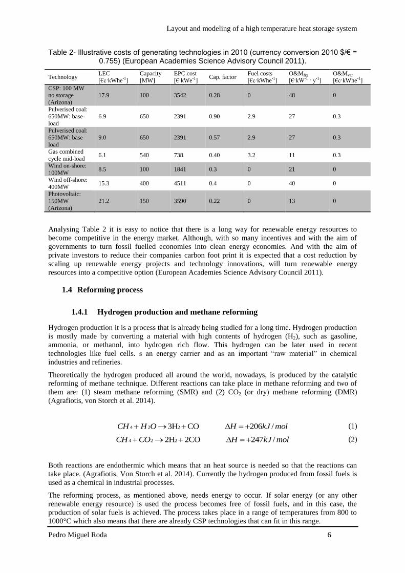
Layout and modeling of a high temperature heat storage system
Pedro Miguel Roda 7
2 Thermal storage Independently of the energy production technology it is a great advantage if the energy is coming from
a versatile dispatchable technology This property enables the technology to provide energy (almost)
on demand It is a fact that solar is a non-dispatchable technology and this represents one of the major
challenges on solar technology
In CSP there is the option to integrate a thermal heat storage system that could maintain the plant
working during cloudy periods and if the thermal storage capacity is big enough during night periods
Currently a lot of the researchers effort is to improve this systems and find one that is feasible and do
not compromise the efficiency of the process and do not increase the cost of the whole plant into
extremely high values
This chapter gives an overview on the different types of thermal storage concepts classification and
materials and their properties
21 Thermal energy storage concepts
There are different concepts for thermal heat storage systems Two groups can be identified active
and passive systems And active storage systems can be independently identified as direct or indirect
This type of classification is independent of the systemrsquos storage material and physical storage (Gil
Medrano et al 2010)
The decision on which type of technology will be used in a certain application depends on operation
temperature boundary conditions and development of the technology
211 Active direct and indirect storage systems
An active direct storage system is a more difficult system to implement because in this system the
storage material is also the heat transfer fluid which means that is necessary to find a material that can
be a good heat transfer fluid and a good storage material decreasing the options that can fit in both
An indirect storage system usually makes use of two different materials one is the heat transfer fluid
and other one is the storage material and by pumping the heat transfer fluid through a heat exchanger it
will heat up the storage material that is also being pumped Usually this is a more complex system in
terms of infrastructures because tanks are needed (Gil Medrano et al 2010) A scheme of these
concepts can be seen in Fig 3
Fig 3 - Scheme of active direct (left) and active indirect (right) storage systems
212 Passive storage systems
In a passive storage system the heat transfer fluid will be pumped through another medium that will be
the storage material in this system the storage material is not being pumped and the heat transfer fluid
is just used to charge or discharge the storage system (Gil Medrano et al 2010) A scheme of this
storage concept can be seen in Fig 4
Layout and modeling of a high temperature heat storage system
Pedro Miguel Roda 8
Fig 4 - Scheme of a passive storage system
The most common storage systems applied until now are the indirect storage system and the passive
systems (or regenerators) On the next section there will be a detailed description about the storage
medium and physical storage
22 Storage Media
The storage system can have different storage media such as liquid solid or gaseous the system can
also make use of different physical phenomena to store energy by heating up a medium without phase
change making use of a phase change of a material at a certain temperature or by chemical reactions
that are completely reversible
On the following sections a detailed description on each storage media and some of their applications
is presented
221 Sensible Heat Storage
Sensible heat storage means that the energy will be stored in a material without its phase change It is
important to make a wise choice of material as well as an intensive study of its behavior under
operating conditions The material can be liquid solid or gaseous and it will store energy accordingly
with (3) (Hasnain 1998)
∆11987612 = 119898 int 119888119901(119879)119889119879
1198792
1198791
(3)
2211 Sensible heat storage materials
As it is mentioned above the storage material choice is a crucial point in heat storage systems The
material has to have desired properties for the application And even when different physical heat
storage will be presented the storage materials will have a lot of properties in common A list of
desired properties of storage materials to be implemented in a sensible heat storage system are
Layout and modeling of a high temperature heat storage system
Pedro Miguel Roda 9
presented below and categorized in thermo-physical-(A) chemical-(B) mechanical-(C) economic-
(D) and environmental (E) properties (Khare DellAmico et al 2013)
(A)
bull High energy density
bull High thermal conductivity
bull High heat capacity
bull High density
bull Long thermal cycling stability
(B)
bull Long thermal chemical stability with no chemical decomposition
bull Non-toxic
bull Non-explosive
bull Low corrosion potential or reactivity to heat transfer fluids
bull Compatible with materials of construction
(C)
bull Good mechanical stability
bull Low coefficient of thermal expansion
bull High fracture toughness
bull High compressive strength
(D)
bull Cheap and abundant materials
bull Low cost of manufacturing into suitable shapes
(E)
bull Low manufacturing energy requirement
bull Low CO2 foot print
After evaluating the properties requirements for a certain application a short list of materials should be
elaborated and the materials should be intensively studied Find if the material deteriorates under
operating conditions feasibility and thermal behavior For high temperature applications the most
promising materials are ceramics and metals (Khare DellAmico et al 2013)
2212 Sensible heat storage concepts
The two main concepts of sensible heat storage systems are solid and liquids which will be explained
in detail on the following points
bull Solids
Chose a solid material as a storage the storage material is usually a choice based on its low
cost When solids are used ordinarily concrete leakages phase changes freezing or
evaporation problems are not faced On the other hand solids durability degradation after
several cycles of use and their low thermal conductivity represent the biggest
disadvantages of this concept (Shukla 1981)
Layout and modeling of a high temperature heat storage system
Pedro Miguel Roda 10
bull Liquids
Liquids have the high thermal conductivity as their big advantage but for high
temperatures they have to be pressurized Freezing and boiling points are the biggest
challenges on sensible heat storage systems using liquids as storage material which also
makes it a more difficult storage material to store (Shukla 1981)
There are already few systems implemented under investigation or in test campaigns On the
following sections some examples of both concepts are presented
2213 Examples of sensible heat storage systems
bull Concrete
Concrete is a tempting option since it is a relatively cheap material it is widely use around
the world and it is abundant
The systems using concrete as storage material consist of concrete block that is crossed by
a tube matrix The heat transfer fluid flows through the tubes and heats up the concrete
block This concept has already been tested and concrete showed a great durability
performance Although the system requires a huge area to be installed and its low thermal
conductivity has to be improved which represent the biggest disadvantages of the system
Thermal stability of concrete was evaluated but only for temperature ranges of 400 -
500degC For this temperature ranges a concrete storage test module was built and tested in
The system was tested in a temperature range between 400 - 500degC in Stuttgart
Germany (Laing Bahl et al 2012) A system sizing determination for the parabolic
through solar thermal power plant of the ANDASOL-type was calculated and a 50000 m3
is required and has to be built in a modular approach (Laing Bahl et al 2012)
Some solutions for the poor thermal performance due to concretersquos low thermal
conductivity (range 12 ndash 145 W m-1
K-1
) were investigated and an improvement of
around 15 was achieved by adding structures with high thermal conductivity (Laing
Steinmann et al 2008)
bull 2 Tank molten Salt Indirect Storage
The two tank system is one of the most storage systems implemented This system uses
liquid as the storage media This heat storage system consists of 2 tanks one hot tank and
one cold tank During charging the salt from the cold tank is pumped through the heat
exchanger and is heated up by the heat transfer fluid and stored in the hot tank During the
discharging cycle the direction is reversed and the hot salt heats up the heat transfer fluid
and is stored in the cold tank If the heat transfer fluid is also used as storage material the
heat exchanger is not needed in the systems
This is system was successfully tested in the Solar Two project and its operating
temperatures are between 290-390degC using a molten salt mixture This system is always
limited by the molten salt allowable operating temperatures because the mixture cannot
freeze inside the tanks or pipes system it limits the lowest temperature And since
corrosivity increases with the temperature for molten salts tankrsquos materials have to be
chosen carefully And the mixturersquos thermal performance can be affected in higher
temperatures (Kolb 2011 Dunn Hearps et al 2012)
bull Steam accumulator
Steam accumulators systems are storage systems for short periods that solar radiation is
not available like cloudy periods since accumulators deliver the energy stored quickly
and its cost are proportional to the pressure vessel used in the system
Steam accumulators make use of the high water thermal conductivity property and since
water is not liquid above 100degC for CSP applications it has to be pressurized The system
Layout and modeling of a high temperature heat storage system
Pedro Miguel Roda 11
is charged by providing steam to the liquid medium of the steam accumulator that will
increase the liquid water temperature For discharging the pressure is lowered and steam
is generated A scheme of this system is presented in Fig 5
Fig 5 - Steam accumulator scheme (Laing 2008)
bull Packed bed (and regenerators)
In a packed bed system the heat transfer fluid flows through a container that is full with
small particles made of materials with high thermal conductivity Regenerators are
structures with high thermal conductivity and the heat transfer fluid flows through them
The regenerator concepts is a known system from the aluminum industry that is carried
out at temperatures around 1100degC usually using ceramics materials
This type of system is implemented in the STJ in Juumllich where is used as heat transfer
fluid and alumina is the storage material and its properties are shown in Table 3 The
storage and heat transfer fluid are in direct contact during chargingdischarging process
The air flows through small channels this structure is typically called honeycomb brick
(Zunft Haumlnel et al 2011) The system has already been tested under operating conditions
between asymp200- 630degC (in March 2010) and it has a good thermal performance delivering
air almost at constant temperature when discharging (Zunft Haumlnel et al 2011)
A pebble bed regenerator was investigated by Fraunhofer UMSICHT making use of
extremely small spherical materials (3 to 12 mm diameter) if alumina oxide pebbles are
used the system can reach high temperatures since the maximum operating temperature
for this material is 1800degC (Daschner Binder et al 2013)
Table 3 - Material characteristics
Honeycombs
Material Alumina porcelain (C130)
Specific heat capacity 088 kJ(kgK)
Thermal conductivity 21 W(mK)
222 Latent heat storage
Latent heat storage systems make use of the release of heat during a phase change of a material This
concept has the advantage that it can occur almost at a constant temperature The process should be
reversible so the material will not change its properties after several cycles It is also mandatory that
all the material can be converted to the previous phase completely (Hasnain 1998) In this system it is
even more crucial an accurate choose of material that can fit to the specific application
Layout and modeling of a high temperature heat storage system
Pedro Miguel Roda 12
2221 Material to be used as PCM
It is expectable that the most investigated phase transition would be the transitions that release more
energy although the early investigations began with the phase change solid-liquid that usually releases
less energy than the liquid-vapor transitions This is explained that a better container is needed and
also leaking problems are more likely to happen when leading with gases (Abhat 1983)
As it is mentioned above the material should match the specific operating temperature range almost
perfectly The properties of the material even that they are similar to the properties of the materials
used for sensible heat they should have some specific performance due to their phase change usage
The thermodynamic (A) kinetic (B) chemical (C) and economic (D) criteria used to evaluate PCM
materials are (Abhat 1983)
The phase change material (PCM) should possess
(A)
bull A melting point in the desired operating temperature range
bull High specific latent heat of fusion
bull High density which reduces the container (storage) volume
bull High specific heat capacity to provide for significant additional sensible heat storage
effects
bull Congruent melting the material should melt completely so that the liquid and solid phases
are identical in composition otherwise the difference in densities between solid and
liquid cause segregation resulting in changes in the chemical composition of the material
(Abhat 1983)
bull Small volume changes during phase transition so that a simple containment and heat
exchanger geometry can be used (Abhat 1983)
(B)
bull Little or no super cooling during freezing the melt should crystallize at its thermodynamic
freezing point This is achieved through a high rate of nucleation and growth rate of the
crystals (Abhat 1983)
(C)
bull Chemical stability
bull No chemical decomposition so that a high latent thermal energy storage system life is
assured (Abhat 1983)
bull Non-corrosiveness to construction materials
bull The material should be non-poisonous non-flammable and non-explosive
(D)
bull Available in large quantities
bull Inexpensive
In order to evaluate the properties of the material after several cycles under operating conditions the
melting and freezing characteristics of the material should be evaluated before Abhat (1983) suggests
Layout and modeling of a high temperature heat storage system
Pedro Miguel Roda 13
that two measurement techniques can evaluate these characteristics Differential Scanning Calorimetry
and thermal analysis
Table 4 gives a summary of phase change materials A more complete and detailed list of phase
change materials is presented in Caacuterdenas and Leoacuten (2013) work
Table 4 - Melting temperature for different compounds
Temperature range
[degC] Material
Transition
temperature [degC] Heat of fusion [kJkg]
0 -100
Water
Paraffin
Salt hydrate
0
20-60
30-50
335
140-280
170-270
100-400
AlCl3
LiNO3
Na2O2
192
250
360
280
370
314
400-800
50LiOH50LiF
KClO4
LiH
427
527
699
512
1253
2678
800-1500
LiF
NaF
MgF2
Si
868
993
1271
1415
932
750
936
1654
The storage capacity of a latent heat storage system in phase transition solid-liquid is given by (4)
(Portaspana 2011)
Tm
Ti
Tf
Tm
pmmp dTCmhadTCmQ (4)
2222 Latent heat storage systems
It is mentioned in the previous section that latent heat storage systems have the advantage that the
process of charging and discharging can be carried out in an almost isothermal condition making use
of the heat released or consumed by phase change Although most of the phase change materials have
low thermal conductivity In order to have an efficient latent storage system this property has been
investigated recently and a lot of investigators try to find a solution to improve it (Caacuterdenas and Leoacuten
2013)
A popular project that presented some solutions for the challenges in latent heat storage systems is the
DISTOR project (Steinmann and Tamme 2008) The solutions presented in the project are
bull Extended heat transfer area
This approach suggests that if the heat transfer fluidrsquos container area in contact with the
PCM is larger the phase change will occur faster because the distance for heat transfer
between the container and the solid PCM is reduced
bull Composite material with increased thermal conductivity
Materials with extremely high thermal conductivity are added to the PCM
Some applications using these solutions are presented on the following section
Layout and modeling of a high temperature heat storage system
Pedro Miguel Roda 14
2223 Examples of latent heat storage systems
bull Sandwich design
Typically latent heat storage systems consist of a tube (or container) where the heat
transfer fluid is flowing and this tube is in contact with the phase change material When
charging usually the phase change material is changing its phase from solid to liquid If
the thermal conductivity of the phase change material is low the process is much slower
and inefficient and what can occur is that part of the material is still solid by the end of the
charging period
The sandwich design consists in the addition of a structure in between of the phase
change material with high thermal conductivity These structures are added in parallel to
to each other and perpendicular to the tube containing the heat transfer fluid (Steinmann
and Tamme 2008)
Fig 6 shows the scheme of a storage unit of the sandwich concept Foils made of
exfoliated graphite are combined with PCM to form a sandwich structure
Fig 6- Schematic of the sandwich concept using graphite foil (Steinmann and Tamme 2008)
Cascaded PCMs
The latent heat storage systems as it is mentioned before make use of a phase change in a
material that occurs almost at constant temperature The performance of these systems
depends on the temperature difference between the PCM and the heat transfer fluid During
charging process the heat transfer fluid is transferring heat to the PCM that is changing its
phase although the heat transfer fluid will also decrease its own temperature Which means
that until the heat transfer fluid leaves the system on the outlet the process is less efficient on
the end part of the system (if we only consider along the x axis)
Some investigations suggest that if the difference between the PCM and the heat transfer fluid
is kept constant along the whole process the system has a much better performance What the
Layout and modeling of a high temperature heat storage system
Pedro Miguel Roda 15
investigations suggest is that a series of PCM is placed in series next to each other where the
phase change temperature is lowering from the left (inlet during charging) to the right (outlet
during charging) this temperature is constant along the whole process and a constant heat flux
is also achieved this approach is usually called cascaded PCM (Jegadheeswaran and Pohekar
2009) Fig 7 shows an example of a cascaded heat storage system
Fig 7 - Example of a cascaded latent heat storage system (Michels and Pitz-Paal 2007)
Experimental investigations with three PCMs sodium nitrate NANO3 a eutectic mixture of
potassium nitrate and potassium chloride KNO3KCl and potassium nitrate KNO3 were
carried out by (Michels and Pitz-Paal 2007)
Michels and Pitz-Paal (2007) work show that when this approach is used a bigger amount of
PCM changes its phase when compared with systems that only use a single PCM they
determined that when using the cascaded approach the PCM material that experiments a phase
change is around 92 during charging process and 67 during discharging process Even
when using a single PCM that the whole material experiences a phase change during charging
process during discharging process only 2 of the material experiences a phase change
Lithium carbonate Li2CO3 prototype
This prototype uses Lithium carbonate Li2CO3 as PCM material and makes uses of copper to
improve the thermal performance of the PCM Verdier Ferriegravere et al (2014) performed
numerical simulations that can be analyzed The system is in equilibrium ate the beginning
and is set on a uniform temperature of 700degC To charge the system a temperature of 900degC is
set as boundary condition on the bottom part of the structure To evaluate the discharging
process of the system a boundary condition of 100degC is set on the bottom of the structure and
before the discharging process begins a uniform temperature of 900degC is assumed for the
system The concept of the system analyzed is showed in Fig 8
Fig 8 - 3D representation of the concept (Verdier Ferriegravere et al 2014)
Layout and modeling of a high temperature heat storage system
Pedro Miguel Roda 16
The numerical results are shown in Fig 9
Fig 9 - Evolution of the PCM temperature during heating (left) and cooling (right) phase (Verdier
Ferriegravere et al 2014)
T1 T3 T5 and T7 are temperatures closer to the fin and T2 T3 T4 and T8 are located in the
center of the compartment
Fig 9 shows the results of the numerical investigations performed by Verdier Ferriegravere et al
(2014) Here a comparison with a system using only PCM without the copper fins was not
made So the only results that can be evaluated is that the system takes around 4h to be
completely charged and 25h to be completely discharged
More investigations and comparisons between traditional latent heat storage systems and system with
the integration of material with high thermal conductivity should be made to really determine its
advantages and influences on the system
223 Thermochemical heat storage
On thermochemical heat storage it is taken advantage of enthalpy but instead of a phase change like in
latent heat storage this system makes use of the completely reversible endothermic chemical
reactions The concept of this system is to absorb the excess heat in an endothermic reaction and store
the products on separate containers During discharging the products are combined exothermically and
the heat of reaction can be used
These systems are far behind in maturity when compared with sensible or latent heat storage systems
but they represent a promising solution due to their high energy density and by the possibility to store
energy at ambient temperature
Like the other systems presented above a proper choice of the materials should be evaluated on the
next section the material choice and properties are presented
2231 Properties of reactions considered for thermochemical energy
storage systems
On thermochemical the properties are related to compounds and reactions On this type of storage
systems the properties chased are even more peculiar and crucial
Necessary properties of the compounds to be used as thermochemical heat storage as told in
Portaspana (2011) work are
Reversibility
No side reactions or changes in reaction rate with the time should occur The reaction should
be completely reversible (Portaspana 2011)
Layout and modeling of a high temperature heat storage system
Pedro Miguel Roda 17
Reaction rates
Both forward and reverse reactions must be rapid enough to absorb all the available energy or
release it promptly The reaction rates must not decrease with cycling Such a decrease can be
observed if structural changes of the storage medium occur (Portaspana 2011)
Controllability
The reactions must be controllable because they have to be turned on and off when required
Controllability is achieved by product separation by controlling the temperature and pressure
or by catalysts (Portaspana 2011)
Ease of storage
The reaction products have to be easily separable prior to storage Reactions must not occur at
storage temperature (Portaspana 2011)
Safety
Toxicity inflammability and corrosiveness of the reaction products may pose unacceptable
safety hazards (Portaspana 2011)
Cost
Cost should be as low as possible which requires materials which are readily available
(Portaspana 2011)
On the following section will be presented some reactions considered for thermochemical heat storage
2232 Examples
Ammonia dissociation
When a thermochemical heat storage system is being implemented it will occur in a reactor
An important detail when evaluating promising reactions is if the process is already well-
known in other applications This is the case of ammonia dissociation reaction (5) the heat
recovering reaction is the well-known Haber Bosch process usually employed for fertilizer
production Ammonia dissociation has other advantages such as no side reactions occur and it
consists of no aggressive reactants for the environment On the other hand ammonia
dissociation has a relatively low enthalpy of reaction around 665 kJmol (Lovegrove Luzzi
et al 1999) Most of the studies on this reaction as a heat storage system have been carried out
by the Australian National University
223
2
3
2
1HNHNH
(5)
Reduction and oxidation reactions
This is a two-step concept that makes use of the principle of transition between the oxidized
and reduced form of an oxide of a metal that has multiple oxidation states (Agrafiotis Roeb et
al 2014)
On the first step an endothermic reaction (6) takes place with the supply of external heat the
reduced state of the oxide MeOox is obtained as a product (Agrafiotis Roeb et al 2014) The
general reaction is
)()( 2 gOMeOHMeO redox (6)
On the second step an exothermic reaction (7) takes place via an oxygen source If air is used
as the oxygen source the oxidation reaction is as the same structure as (Agrafiotis Roeb et al
2014)
Layout and modeling of a high temperature heat storage system
Pedro Miguel Roda 18
)()(2 HMeOgOMeO oxred (7)
Agrafiotis Roeb et al (2014) present the relevant reversible reactions considered for
thermochemical processes as scheme (8) for metal hydroxides scheme (9) for carbonates and
scheme (10) for oxides
reactmolkJHOHCaOHOHCa 100 )()( 22 (8)
reacmolkJHCOCaOHCaCO 167 )( 23 (9)
reacmolkJHOCoOHOCo 200
2
13)( 243
(10)
Heating cycles between 985 and 785degC were performed by Tescari Agrafiotis et al (2014) in
Co3O4 as well as Co3O4 ndash based binary powder metal oxide compositions under air They
showed on their work that the reactions are completely reversible Tescari Agrafiotis et al
(2014) investigated an hybrid system This hybrid system consists of coating a typical
honeycomb sensible heat storage system The investigation suggests that the system will have
a similar behavior to the plain powder thermochemical system and will improve the ceramic
honeycomb system by increasing the amount of energy stored by the system
Cobalt oxide powder was compressed and become a cobalt oxide pellet and was tested by
Karagiannakis Pagkoura et al (2014) Their work shows that the pellet can slightly improve
the performance of the chemical reaction The results for powder and pellet can be seen in Fig
10
Fig 10 - Comparison of thermochemical redox behavior of cobalt oxide in powder and pellet form
(Karagiannakis Pagkoura et al 2014)
In Fig 10 the red line represents the cobalt oxide pellet and the blue line represents the
powder And by analyzing the peaks it is possible to understand that it is possible to operate in
a wider range of temperatures and recover more heat from the reaction
Miguel Gonzalez-Aguilar et al (2014) are on the early investigations for a fluidized bed
system considering the manganese (III) redox reaction showed in (11)
3224332 OMn of 831 46 molkJHOOMnOMn (11)
Sulfur based thermal energy storage
This thermochemical storage concept consists on storing energy by producing elemental sulfur
for later burning To produce elemental sulfur on a thermochemical process three chemical
reactions take place (12) concentrated sulfuric acid is decomposed by heat into water sulfur
dioxide and oxygen (13) sulfur dioxide undergoes disproportionation in water into sulfuric
Layout and modeling of a high temperature heat storage system
Pedro Miguel Roda 19
acid and elemental sulfur (14) the sulfur generated is directed to storage andor to a sulfur
burner for combustion to generate heat The thermochemical cycle does not produce waste
effluent and does not emit greenhouse gas into the environment (Bunsen Wong 2013)
molkJHgSOgOgOHH 97 )(2)()(2(l)SO2H Decomp SO 222 4242 (12)
)((aq)SO2H)(3 O(l)2H ionDisproport 42222 lsSgSOSO (13)
molkJHgOlsSS 297 (g)SO)( )( Combustion 22 (14)
3 Mathematical model
31 Introduction
In this chapter the thermal interaction between the heat transfer fluid and the storage material of the
system is studied mathematically
The system studied is similar to the one installed in the STJ (Zunft Haumlnel et al 2011) using air as
heat transfer fluid and alumina as storage material
The model objective is to simulate a dynamic state of the thermal storage system during charge and
discharge process as well as to switch between these processes in a continuous simulation run This
ability of switching between charging and discharging conditions in one simulation is of crucial
importance in order to enable the complete simulation of the solar methane reforming plant where the
model will be integrated Determining the relation between the total volume of the storage system and
the number of hours that it can provide heat to operate the plant is also a goal of this work
The model discretizes the storage in a large number of interacting layers providing detailed
information about the temperature distribution within the storage Air flows through the honeycomb
bricks channels to transport the heat to or from the storage The convective heat transfer coefficient
between air and solid is sufficiently large which leads to a small temperature difference between air
and solid during charging or discharging of the system
The storage model presented in this work assumes an ideal storage which means that no heat losses
are taken into account during charging or discharging period During standstill period (when air is not
flowing through the channels) the temperature gradient will remain the same until the next charging or
discharging period starts again
The temperature dependent properties of air and the pressure loss by forced convection have been
considered in this model
The storage model is implemented in Aspen Custom Modelerreg with the appropriate syntax shown in
Appendix A - Aspen Custom Modeler Model Code
In order to reduce the computations time only a single channel of one honeycomb brick is simulated
The same conditions are assumed for each parallel channel so that all the channels will have a similar
behavior since no heat losses to environment are considered The energy stored by the system is then
the product of number of channels by the energy stored in only one channel
Layout and modeling of a high temperature heat storage system
Pedro Miguel Roda 20
311 Storage structure
As mentioned in the previous sections the system modeled is similar to the system installed in STJ
The system installed in STJ consists of a storage chamber made of honeycomb storage elements as
shown in Fig 11
The model will only consider the volume of material capable of storing energy which is the volume of
honeycomb bricks excluding the housing and insulation material The model does not consider any
degradation after a long operating period
311 Storage system general properties
The storage installed in STJ is a regenerator-type Air flows from the top to the bottom of the system
in direct contact with the alumina structure during charging period During discharging the air flow is
reversed
The system installed in STJ is a block with a volume of 120m3 and a height of 3m and operates
between 680 and 120degC with a nominal charge mass flow of 94 kgs Table 5 is a summary of the
storage specifications (Zunft Haumlnel et al 2011)
Table 5 - Storage specifications
Storage specifications
Temperature
range
680 ndash 120 degC
Charge mass
flow
94 kgs
Pressure loss lt1500 Pa
The storage material used is alumina porcelain (C130) and its thermophysical properties are shown in
Table 6 (Zunft Haumlnel et al 2011)
Table 6-Alumina porcelain (C130) properties
Honeycombs 60 x 60 channels
Brick dimensions 15 x 15 x 15 cm
Mass density 2700 kgm-3
Specific heat capacity 088kJ(kg-1K-1)
Themal conductivity 21 W(m-1K-1)
Heating surface 1180 m2m-3
Fig 11 - Honeycomb brick
Layout and modeling of a high temperature heat storage system
Pedro Miguel Roda 21
311 Honeycomb storage principle
The principle of the honeycomb ceramic is identical to other sensible heat storage During the
charging period the hot air flows through the systems micro-channels and releases heat increasing the
material temperature During the discharging period the flow direction is reversed and then cold air
flows through the systems micro channels and absorbs the heat stored in the material resulting in an
increase of the air temperature
As Luo Wang et al (2013) showed the honeycomb ceramic have an excellent heat transfer
characteristic resulting from the larger heat exchange area and fine flow behavior meaning relatively
small pressure drop resulting from the flow-through channels
32 Physical model
Fig 12 shows the physical model which consists of a quadrangular channel with length L and opening
s During the charging process heated air flows through the channel from top to bottom of the
channel During the discharging process the air flow is reversed and cold air is pumped from the
bottom to the top of the channel
The channel is discretized in a certain amount of points between 0 and L with the same spacing
between each other The spacing between each point will return more or less accurate results for a
smaller and larger spacing respectively The spacing will also influence the simulation time so a
optimal situation should be determined where a not so time consuming simulation can be carried out
with reasonable accurate results
Fig 12 - Physical model of the storage system
A temperature gradient is achieved during both processes and the system is considered completely
charged when the air temperature in the outlet exceeds the defined minimum temperature that should
usually be defined according to the outlet temperature of the process ie heat exchangers that the heat
is used in In opposite the system is considered completely discharged when the air outlet temperature
during discharge decreases below the required higher temperature level A representative scheme of
the thermal gradient in the system is shown in Fig 13
Layout and modeling of a high temperature heat storage system
Pedro Miguel Roda 22
Fig 13 - Representative thermal gradient in the storage system
33 Governing Equations
The storage system modeled is a regenerator-type heat storage A regenerator is a type of heat
exchanger in which the hot and cold-fluids occupy the same physical space but at different times
Regenerators necessarily operate in a transient mode The temperatures throughout the system depend
upon time as well as on position Partial differential equations are needed to describe the time and
spatial dependence of the temperature of the solid and the fluid These equations can be identified
using energy balances on the fluid and solid (Nellis and Klein)
The energy equations used to describe the model follow the descriptions and assumptions listed below
Ideal behavior of the system the amount of energy recovered is the same as the amount
stored
The fluid flow inside the storage is vertical from top to bottom during charging and from
bottom to top during discharging
The fluid thermophysical properties are temperature and pressure dependent
The solid thermophysical are temperature independent
There is no heat generation or dissipation inside the storage
The system is well insulated and there are no losses to the ambient
Pressure drop along the channel is considered
The system is one dimensional only temperature gradients along the x axis
The energy equation for the fluid (15) is written as
119899119886119894119903 sdot 119888119901119886119894119903 sdot (
120597119879119886119894119903
120597119909) + 120588119886119894119903 sdot 119888119901119886119894119903 sdot 119860119888119904119886119894119903 sdot (
120597119879119886119894119903
120597119905) = 4 sdot 120572 sdot 119904 sdot (119879119886119894119903 minus 119879119904119900119897)
(15)
The first term on the left side of the equation corresponds to the enthalpy associated with the fluid
flow The second term on the left side of the equation corresponds to the rate of change of enthalpy
The term on the right side of the equation corresponds to the heat exchange by convection between the
solid and the fluid The conduction in the fluid can be neglected due to the small value of air
conductivity
The energy equation for the solid (16) is written as
Layout and modeling of a high temperature heat storage system
Pedro Miguel Roda 23
120588119904119900119897 sdot 119888119901119904119900119897 sdot 119860119888119904119904119900119897 sdot (
120597119879119904119900119897
120597119905) = 119860119888119904119904119900119897 sdot 119896119904119900119897 sdot (
1205972119879119904119900119897
1205971199092 ) + 4 sdot 120572 sdot 119904 sdot (119879119886119894119903 minus 119879119904119900119897) (16)
The term on the left side of the equation corresponds to the change of enthalpy of the solid The first
term on the right side of the equation corresponds to the heat transferred by conduction in the solid
along the x axis The second term on the right side corresponds to the heat transferred by convection
between the particles and the fluid
It is necessary to evaluate the convective heat transfer coefficient α to determine the heat transferred
by convection The convective heat transfer coefficient is affected by the state of the flow and the
shape of the duct and can be determined by (17) using the appropriate Nusselt correlation The heat
transfer convective coefficient is determined locally by the model
120572 =
119873119906 sdot 120582119886119894119903
119904
(17)
In order to use the appropriate correlations an evaluation of the flow state is needed this evaluation is
determined by the Reynolds number A flow is laminar if Re le 2400 and turbulent if Re ge 4000 in
between the flow is in a phase called transition (Yunus and Cimbala 2006) In the presented model the
Reynolds number range is from asymp7 ndash 12 meaning that the flow is in laminar phase The appropriate
Nusselt correlation is a correlation that gives the Nusselt number for a fully developed laminar flow
transferring heat to four walls in a quadrangular duct (18) (Shah and London 1978) which depends on
the side length of the duct entry cross section
119873119906 = 8235 [1 minus 20421 sdot 119886 + 30853 sdot 1198862 minus 24765 sdot 1198863 + 10578 sdot 1198864
minus 01861 sdot 1198865]
with 119886 =119888
119889
(18)
119886 represents the relation between the side length of the duct entry cross section and it is equal to one
for quadrangular ducts
331 Boundary and initial conditions
The temperature in the fluid and solid can be determined by (15) and (16) respectively The solution
of the temperatures depends on the physical conditions existing at the boundaries of the system An
initial condition is also needed since the system is also time dependent
The boundary condition to solve the fluid equation (15) is
The air inlet temperature is constant for all time
119879(0 119905) = 119879119886119894119903119894119899 (19)
The boundary conditions to solve the solid equation (16) are
In the first layer of the solid (since there is no previous layer) the conduction is only to the
next layer so the second derivative term becomes a first order derivative term
120588119904119900119897 sdot 119888119901119904119900119897 sdot 119860119888119904119904119900119897 sdot (
120597119879119904119900119897
120597119905) = 119860119888119904119904119900119897 sdot 119896119904119900119897 sdot (
120597119879119904119900119897
120597119909) + 4 sdot 120572 sdot 119904 sdot (119879119886119894119903 minus 119879119904119900119897)
(20)
In last layer of the solid (since there is no next layer) the conduction is only form the previous
layer so the second derivative term becomes a first order derivative term
120588119904119900119897 sdot 119888119901119904119900119897 sdot 119860119888119904119904119900119897 sdot (
120597119879119904119900119897
120597119905) = 119860119888119904119904119900119897 sdot 119896119904119900119897 sdot (
120597119879119904119900119897
120597119909) + 4 sdot 120572 sdot 119904 sdot (119879119886119894119903 minus 119879119904119900119897)
(21)
Layout and modeling of a high temperature heat storage system
Pedro Miguel Roda 24
The initial conditions at the beginning of the simulation are defined by the solid temperature
The system is in equilibrium and the fluid temperature inside the channel is equal to the solid
temperature
119879119886119894119903(119909 0) = 119879119904119900119897(119909 0) (22)
331 Pressure drop
Pressure drop is a quantity of interest since it is directly related to the power requirements of the fan or
pump to maintain flow which will be further considered when the model is implemented in the solar
methane reforming plant model
The pressure drop inside the channel is considered and was determined by (23) from Yunus and
Cimbala (2006)
∆119901 = 119891 sdot
119871
119863sdot
120588119886119894119903 sdot 1198811198861198941199032
2+ 120588119886119894119903 sdot 119892 sdot 119871
(23)
119891 is the Darcy friction factor and it is defined as (24) for fully developed laminar flow in a
quadrangular duct
119891 =
5692
119877119890 119877119890 =
119881119863
120584 119886119899119889 119877119890 le 2300
(24)
331 Energy balance
In order to make sure that the energy gain by the wall during charging process or the energy loss by
the wall during discharging process is the same as the air enthalpy change and make sure that the
model does not violate the first principle of thermodynamics (conservation of energy) two monitoring
variables were created and their values compared
These two variables are the solid enthalpy change determined by (25) and the air enthalpy change
(26)
119876119904119905119908119886119897119897 = 120588119904119900119897 sdot 119888119901119904119900119897 sdot 119860119888119904119904119900119897 sdot 119871 sdot (
120597119879119904119900119897
120597119905)
(25)
119876119886119894119903 = 119899119886119894119903 sdot [ℎ119886119894119903(119871) minus ℎ119886119894119903 (0)] (26)
34 Model Validation
Is necessary to check the model performance with already existing validated models or compare the
model with experimental data In order to compare the model with experimental data it is necessary to
recreate the model as much close to the real system
To validate this model experimental data and previous works from the system installed in STJ are
available (Zunft Haumlnel et al 2011 Kronhardt Alexopoulos et al 2014) To validate the model the
same properties from the system installed in the STJ are implemented in the model
A comparison between the model implemented in Aspen Custom Modeler and a model built in
Comsol Multiphysicsreg will also be shown in this chapter
341 Comparison with experimental data
A test campaign was performed by Zunft Haumlnel et al (2011) in March 2011 These experiments had
the goal to evaluate the storage performance and the validation of existing simulations and design
tools
Layout and modeling of a high temperature heat storage system
Pedro Miguel Roda 25
The experiments include charging period standstill and discharging performance of the storage
system Different inlet air temperatures and different inlet mass flows were tested and measured in the
test campaign The experimental data is not published in detail
The measured data was difficult to interpret and due to lack of information regarding the
thermocouples location it was not possible to achieve the correct interpretation of the measured data
and it was not also possible to establish a comparison between the model presented in this work and
the test campaign performed by Zunft Haumlnel et al (2011)
341 Comparison with previous validated models
The model presented by Hirsch IRT et al (2012) was validated using measured data from the system
installed in STJ The test boundaries as mass flow inlet temperature and inlet pressure are the
nominal solar tower process values showed in Table 5 The initial temperature gradient inside the
system presented by Hirsch IRT et al (2012) was determined by interpolation of the real temperature
of the storage (this initial gradient is not the discharged gradient it is just the reference point before
one hour charging period) Under these conditions this model is appropriate for validation of the
model created in this work
The comparison between the initial gradient in our model and the model by Hirsch IRT et al (2012) is
shown in Fig 14 The results show a good agreement
Fig 14-Initial gradient comparison between aspen model and (Hirsch IRT et al 2012) model
Horizontal axis is normalized
Another comparison is shown in Fig 15 this comparison is the systems profile temperature after one
hour charging Once again the presented model and the model presented by Hirsch IRT et al (2012)
show a good agreement The deviations can be due that in our model a constant inlet mass flow and
inlet temperature is assumed for the whole hour leading to no oscillations Also the difference in the
initial gradient leads to higher deviations between the two models It is expected that when the system
reaches a periodic steady state operating conditions the deviations are reduced
0
100
200
300
400
500
600
700
800
0 011 022 033 044 055 066 077 088 099
Tem
per
ract
ure
[degC
]
System height (normalized)
TAMM
Hirsch IRT et al (2012)
Layout and modeling of a high temperature heat storage system
Pedro Miguel Roda 26
Fig 15 - After one hour charging gradient comparison between Aspen model and (Hirsch IRT et al
2012) model Horizontal axis is normalized
341 Comparison with a Comsol Multiphysicsreg model
The model presented in this work simulates the behavior of one channel of the whole system A
channel of the whole system is a certain number or honeycomb bricks disposed in series on top of each
other until it reaches 3 meter high In our model to achieve the 3 meter height 20 models are connected
in series since every honeycomb brick has 15cm length as shown in Table 6
Aspen Custom Modelerreg is a powerful tool and enables to perform complex calculations and
simulations using a simple syntax and in short period of time Comsol Multiphysicsreg model is also a
powerful tool and also enables the creation of a 3D picture of the system In order to get a better
understanding of the system a simple Comsol Multiphysicsreg model was created
Comsol Multiphysicsreg model
The comsol model consists of a honeycomb channel The alumina properties applied are the same
shown in Table 6 and the air themophysical properties are temperature dependent
The boundary conditions applied in the Comsol model are
Constant inlet temperature of 680ordmC
Adiabatic outer walls of the channel
Constant inlet pressure
Outlet velocity asymp006 ms
The system is in an equilibrium state of 150ordmC in the beginning The system is evaluated after one hour
under these conditions and results are presented in Fig 16
0
100
200
300
400
500
600
700
800
0 011 022 033 044 055 066 077 088 099
Tem
per
ract
ure
[degC
]
System height (normalized)
TAMM
Hirsch IRT et al (2012)
Layout and modeling of a high temperature heat storage system
Pedro Miguel Roda 27
Fig 16 - Comsol results after one hour simulation
When this model is compared with the model created in Aspen that need to be connected in series the
results shown a good agreement with slight deviations The results curves are shown in Fig 17 In Fig
17 Tcomsol corresponds to the Comsol model data TAMM corresponds to the model created in
Aspen where several models are connected in series and TALCM corresponds to the model created in
aspen where a single long channel is simulated
Fig 17 - Comparison with comsol model
341 Comparison between Aspen Models
The model presented in this work shows a good agreement with validated models using measured
data But in order to implement our model in the complete solar methane reforming process model this
connection of blocks is extremely difficult to handle when a transient simulation is carried out due to
the fact that the charging outlet becomes the inlet during discharging of the system In order to
simplify this issue a single model of 3 meter height was created The main difference between a model
of 3m length and 20 models of 15cm length connected in series is that in the 3m length single model
thermal conduction between 2 consecutive bricks occurs
0
100
200
300
400
500
600
700
0 002 004 006 008 01 012 014
Tcomsol
TAMM
TALCM
Layout and modeling of a high temperature heat storage system
Pedro Miguel Roda 28
In order to make sure that thermal conduction between consecutive bricks will not lead to inaccurate
results the two aspen models are compared The curve of the first 15cm of the long channel aspen
model (represents the first brick) is also plotted in Fig 17 In the end of the curve a slight deviation
from the Comsol model and the aspen multiple bricks model can be noticed
Although if the complete systems are compared they show a good agreement here for simplification a
Comsol model is not considered
Regarding the conduction in a long channel can lead to high deviations in low dimensions as shown in
Fig 17 but when compared to the complete system these deviations are negligible as shown in Fig 18
where the series connected model and the single long model in Aspen are compared In Fig 18 the
curves cannot even be distinguished due to superposition
Fig 18 - Comparison between the two different Aspen models
35 Validation discussion
The model created is validated with the previous shown data comparison In order to reduce the
simulation time and the complexity of the system a model of a long single brick will be used to
simulate the system in operation and implemented in the complete solar methane reforming process
model Although this assumption is not completely accurate the deviation from accurate modelling is
small as the validation shows
In the next section a sizing of the system to be implemented will be shown since the solar methane
reforming plant characteristics are different from the STJ
4 System sizing
41 Introduction
In this section a relation between the total volume of the storage material and the solar methane
reforming plant operating hours is presented
As shown in Fig 19 the air is heated up in the solar receiver and pumped to the reformer The solar
methane reforming is designed to operate under constant conditions which means that the air mass
flow and temperature reaching the reformer should be constant during operation The heat storage
system is implemented in parallel to the reformer and the exceeding air during solar radiation period
is used to charge the heat storage system
0
100
200
300
400
500
600
700
800
0 05 1 15 2 25 3
TAMM
TALCM
Layout and modeling of a high temperature heat storage system
Pedro Miguel Roda 29
The charging mass flow to the heat storage system is adjusted enabling a constant air mass flow
delivered to the reformer at a constant temperature of 900 degC
Fig 19 - Solar methane reforming plant with storage scheme
42 Mass flow variation
The air mass flow available at 900 degC depends on the incident solar radiation at a certain time If the
intercept radiation is lower than 15 MWh no air mass flow is available at the desired temperature and
525 MWh is the maximum intercept radiation available
The air mass flow available to the storage system can be determined by (27) The total air mass flow
available varies with the time due to the solar radiation and the air mass flow to the reforming process
is constant
119886119894119903 119905119900 119904119905119900119903119886119892119890 = 119886119894119903 119905119900119905119886119897 minus 119886119894119903 119905119900 119903119890119891119900119903119898119890119903 (27)
Data for the intercept radiation for each hour of the year and the respective air mass flow available for
one channel of the system is evaluated and the first 58 hours correspondences are shown in Appendix
B
43 Energy available
The energy available for storage will be the enthalpy variation of the correspondent air mass flow
available for the storage system during that hour
The outlet temperature of the air after the reforming process is 368 degC and this also corresponds to the
outlet temperature of the heat storage system during charging period The energy available will be the
enthalpy variation of the air from 900 to 368 degC and it is determined by (28)
119905119900119904119905119900119903119886119892119890 = 119886119894119903 119905119900 119904119905119900119903119886119892119890 sdot [ℎ119886119894119903900 minus ℎ119886119894119903368] (28)
Layout and modeling of a high temperature heat storage system
Pedro Miguel Roda 30
A balance for each hour of the year is done (29) During charging period the energy stored is summed
and subtracted if a discharging period is taking place With this energy approach a maximum energy
stored in the system is determined
119876119878119905119900119903119886119892119890(119905 + Δ119905) = 119876119878119905119900119903119886119892119890(119905) + 119905119900119904119905119900119903119886119892119890 sdot Δt (29)
44 Operating hours
The operating hours will vary with the air mass flow designing point of the solar methane reforming
plant
If the air mass flow is set to a low value a higher air mass flow is available to store energy in the
storage system This will enable the solar methane reforming to operate for more hours and the plant
size decreases for a fixed product output when the operating hours are increased In an extreme
scenario the solar methane reforming plant could operate the 8760 hours of one year Although that
the plant could operate the whole year this is not the optimum scenario since the storage volume
required would become huge
45 System volume and shape
The volume of the storage material needed will vary with the operating hours A bigger volume is
needed for more operating hours and a smaller volume is needed for less operating hours
The shape will affect mainly the pressure drop of the system which increases with the length of the
system
Knowing the maximum energy to be stored in the system (determined on the previous point) the
material mass density the material heat capacity and the temperature difference that the system will
operate (in the solar methane reforming plant the temperature range is 900 ndash 368 degC) the storage
material volume needed can be determined by (30)
119881119904119905119900119903119886119892119890 =
119876119905119900119904119905119900119903119886119892119890119898119886119909
120588119904119900119897 sdot 119888119901119904119900119897 sdot ∆119879
(30)
46 System design
With all the information presented in the previous points it is possible to establish a relation between
the operating hours of the solar methane reforming plant and the volume of the storage material This
relation is shown in Fig 20 The maximum of the storage material needed is reached if the plant is
operated continuously for the whole year But this relation is not linear and if the plant is operated for
around 80 of the time the storage material volume needed decreases to around 5 of the maximum
volume needed to operate 100 of the time
Layout and modeling of a high temperature heat storage system
Pedro Miguel Roda 31
Fig 20 - Relation between operating hours of the plant and storage material volume needed Vertical
axis is normalised
The volume needed plotted in Fig 20 does not include housing and insulation material Part of the
material is not heated up (during charging period) or cooled down (during discharging period) because
the temperatures of the outlet cannot exceed the design parameters extra volume should be considered
when the system is implemented in the solar methane reforming plant
461 Reference case
After evaluating the previous results a reference case to simulate the performance of the system should
be set The chosen case is the point immediately before the volume rises exponentially In this case the
plant does not operate for a low number of hours and the system is kept as small as possible The
reference case parameters are shown in Table 7
Table 7 - Reference case parameters
Reference case parameters
Material mass density 2700 [kgm-3]
Material heat capacity 088 [kJ(kg-1K-1)]
Temperature difference 532 [K]
Maximum energy Stored 889 [GJ]
Storage material volume needed 7035 [m3]
Dimensions asymp89times89times89 m
Not operating hours 1785 [h]
When this approach is made it is necessary that the complete volume of the storage material changes
its temperature (form 368 to 900 degC in our application) and that it is no possible since the outlet
temperature of the system cannot rise above the set parameters It is necessary to increase the length of
the system in order to keep the outlet temperature inside its boundaries values
462 Charged and discharged gradients regarding extra length
The extra length needed to the system is determined by running a simulation under an ldquoenergy storedrdquo
condition This condition stops the simulation when the maximum energy stored in the system is
0
01
02
03
04
05
06
07
08
09
1
0 20 40 60 80 100
Vo
lum
e
Operating time
StorageMaterialvolumeneeded
Layout and modeling of a high temperature heat storage system
Pedro Miguel Roda 32
achieved during charging period (to the maximum energy stored value it is summed the value of the
energy stored in the system when it is fully discharged since this energy will not be recovered from
the system in order to guarantee that during discharging period the outlet temperature will not come
below the temperature needed in the process) The simulation is run with a much higher length than
the determined in the reference case When this charged state is achieved the system profile
temperature is evaluated and the outlet is set where the material did not experience any temperature
change This guarantees that when the fully charged condition is achieved the outlet temperature does
not exceed the minimum temperature of the process
After the simulation the total height of the system is determined The dimensions of the system are
showm in
Table 8 - System final dimensions
Reference case parameters
Cross section asymp89times89 m
Height asymp35m
Total volume asymp2772 [m3]
When the system is discharged the outlet temperature of the system cannot go below 900degC In Fig 21
is shown the discharged gradient of the system for the reference case regarding the extra length
needed to fulfill the required outlet temperature
Fig 21 - Reference case discharged temperature gradient considering extra length
When the system is completely charged the outlet temperature of the system cannot rise above 368degC
In Fig 22 is shown the charged gradient of the system for the reference case The outlet during
discharged is located on the left of the x axis (the flow is reversed when charging or discharging)
300
400
500
600
700
800
900
1000
0 5 10 15 20 25 30 35 40
Tem
per
atu
re [
degC]
Systems height [m]
Discharged
Layout and modeling of a high temperature heat storage system
Pedro Miguel Roda 33
Fig 22 - Reference case charged system temperature gradient considering extra length
47 Reference case results
A simulation for the whole year will be carried out for the reference case system An energy balance in
the storage system was determined using an excel sheet and the first 8 hours of this energy balance are
shown in Table 9 When the air to storage is a negative number means that the system is in discharging
period The values presented in Table 9 are results for the whole system
The simulations results and the predicted values show a good agreement with a slight deviation that
can be due to calculations approximation
Table 9 - Simulations results for the first 8 hours of the whole year
Hour Intercepted
Radiation
[MWh]
Air flow to
storage
[kmolh-1]
Energy to storage
[kJh-1]
Energy
accumulated in
the storage [kJ]
Simulation
energy
accumulated
results [kJ]
Error
1 3298 1665099758 2860384958 2860384958 285705133 012
2 4955 475274243 8164479573 1102486453 1101208254 012
3 525 5288722731 9085211188 2011007572 2008675251 012
4 525 5288722731 9085211188 2919528691 2916143713 012
5 525 5288722731 9085211188 382804981 3823613101 012
6 525 5288722731 9085211188 4736570929 4731083209 012
7 41 3216387444 5525258305 5289096759 528296684 012
8 3086 1299706711 2232695974 5512366356 5505977262 012
9 0 29927223 -5028518322 5009514524 5003701682 012
5 Conclusions Energy storage will play a major role in the future of the solar technologies when an energy storage
system is available the utilization of these technologies will increase and will allow solar power to be
produced on demand Energy storage will allow a solar power plant to keep producing energy during
cloudy periods or night period when it is needed the most And will increase the capacity factor of the
plants without fossil fuel backup
300
400
500
600
700
800
900
1000
0 5 10 15 20 25 30 35 40
Tem
per
atu
re [
degC]
Systems height [m]
Charged
Layout and modeling of a high temperature heat storage system
Pedro Miguel Roda 34
The main objective of this work was to model a high temperature heat storage system and predict its
layout in order to overcome the intermittence of the sun as the energy source and to enable the
operation of the plant under constant conditions The type of system chosen to model was a sensible
heat storage system due to the huge amount of information available about these systems
The state of the art in thermal heat storage system is the two tank technology Although that
technology did not fit to the reforming process due to the temperature boundaries related to the two
tanks system
The model was validated using data of previous works that modelled the same system A simulation
for the whole year will be carried out and for the first period of the simulation the results of the
system performance show an excellent agreement with the predicted values The model can be easily
adapted to other applications that want to make use of a sensible heat storage system since the inputs
and dimensions can be easily changed
One major limitation of the model is the neglecting of thermal losses to the environment even if those
losses play a minor role in the system this losses can become an optimization work of the model in a
near future Also the degradation of the material after a long operating period should also be evaluated
in the future since these degradation can lead to thermophysical properties variation of the material
An optimization of the model that can be carried out in the future is the determination of the housing
and insulation material needed to install a complete system
One of the main disadvantages of this system is the huge amount of area required to install it
Investigations in this field should be carried out in the future in order to reduce the volume of the
system
The major advantages of the system are its reliability and the fact that these system are close to other
applications in industry which makes it an already known technology
6 References
Abhat A (1983) Low temperature latent heat thermal energy storage heat storage materials Solar
Energy 30(4) 313-332
Agrafiotis C et al (2014) Exploitation of thermochemical cycles based on solid oxide redox
systems for thermochemical storage of solar heat Part 1 Testing of cobalt oxide-based powders
Solar Energy 102 189-211
Agrafiotis C et al (2014) Solar thermal reforming of methane feedstocks for hydrogen and syngas
productionmdashA review Renewable and Sustainable Energy Reviews 29 656-682
Agrafiotis C et al (2014) Solar thermal reforming of methane feedstocks for hydrogen and syngas
production - A review Renewable and Sustainable Energy Reviews 29 656-682
Bunsen Wong L B Robert Buckingham Dennis Thomey Martin Roeb and Christian sattler (2013)
Sulfur based thermochemical energy storage for concentrated solar power SolarPACES2013
Conference
Caacuterdenas B and N Leoacuten (2013) High temperature latent heat thermal energy storage Phase change
materials design considerations and performance enhancement techniques Renewable and
Sustainable Energy Reviews 27(0) 724-737
Layout and modeling of a high temperature heat storage system
Pedro Miguel Roda 35
Coelho B et al (2010) Solmass projectndashsolar biomass dual hybrid 4 MW CRS pilot plant
SolarPACES Symposium Perpignan
Daschner R et al (2013) Pebble bed regenerator and storage system for high temperature use
Applied Energy 109 394-401
Dunn R I et al (2012) Molten-salt power towers newly commercial concentrating solar storage
Proceedings of the IEEE 100(2) 504-515
European Academies Science Advisory Council (2011) Concentrating Solar Power Its Potential
Contribution to a Sustainable Energy Future EASAC Policy Report 16 EASAC
Gil A et al (2010) State of the art on high temperature thermal energy storage for power
generation Part 1mdashConcepts materials and modellization Renewable and Sustainable Energy
Reviews 14(1) 31-55
Hasnain S (1998) Review on sustainable thermal energy storage technologies Part I heat storage
materials and techniques Energy Conversion and Management 39(11) 1127-1138
Hirsch T et al (2012) DLR Institute for Solar Research (DLR)
Jegadheeswaran S and S D Pohekar (2009) Performance enhancement in latent heat thermal
storage system a review Renewable and Sustainable Energy Reviews 13(9) 2225-2244
Karagiannakis G et al (2014) Monolithic Ceramic Redox Materials for Thermochemical Heat
Storage Applications in CSP Plants Energy Procedia 49 820-829
Khare S et al (2013) Selection of materials for high temperature sensible energy storage Solar
Energy Materials and Solar Cells 115 114-122
Kolb G J (2011) Evaluation of annual performance of 2-tank and thermocline thermal storage
systems for trough plants Journal of Solar Energy Engineering 133(3) 031023
Kronhardt V et al (2014) High-Temperature Thermal Storage System for Solar Tower Power
Plants with Open-Volumetric Air Receiver Simulation and Energy Balancing of a Discretized Model
Energy Procedia 49 870-877
Laing D (2008) Solar thermal energy storage technologies Energy Forum 10000 Solar Gigawatts
23 April 2008
Laing D et al (2012) High-temperature solid-media thermal energy storage for solar thermal power
plants Proceedings of the IEEE 100(2) 516-524
Laing D et al (2008) Solid media thermal storage development and analysis of modular storage
operation concepts for parabolic trough power plants Journal of Solar Energy Engineering 130(1)
011006
Layout and modeling of a high temperature heat storage system
Pedro Miguel Roda 36
Lovegrove K et al (1999) A solar-driven ammonia-based thermochemical energy storage system
Solar Energy 67(4) 309-316
Luo Z et al (2013) Simulation and Experimental Study on Long Term Sensible Thermal Energy
Storage in Solar Thermal System SolarPACES2013
Michels H and R Pitz-Paal (2007) Cascaded latent heat storage for parabolic trough solar power
plants Solar Energy 81(6) 829-837
Miguel S et al (2014) 100-Wh Multi-purpose Particle Reactor for Thermochemical Heat Storage
in Concentrating Solar Power Plants Energy Procedia 49 676-683
Muumlller-Elvers C et al (2012) Design and Construction of Molten Salt Parabolic Trough HPS
Project in Eacutevora Portugal Proc SolarPACES
Muumlller-Steinhagen H and F Trieb (2004) Concentrating solar power A review of the technology
Ingenia Inform QR Acad Eng 18 43-50
Nagl S et al (2011) The economic value of storage in renewable power systems-the case of thermal
energy storage in concentrating solar plants EWI Working Paper
Nellis G and S Klein Heat Transfer Cambridge University Press
Pitz‐Paal R et al (2013) Solar Thermal Power Production Transition to Renewable Energy
Systems 307-338
Portaspana J C (2011) MASTER THESIS High temperature thermal energy storage systems based
on latent and thermo-chemical heat storage Universitaumlt Wien
Shah R K and A L London (1978) Laminar flow forced convection in ducts a source book for
compact heat exchanger analytical data Academic press
Shukla K (1981) Thermal energy storage for solar power generation state of the art Heat Transfer
Engineering 3(2) 62-72
Steinmann W-D and R Tamme (2008) Latent heat storage for solar steam systems Journal of
Solar Energy Engineering 130(1) 011004
Storch H V et al (2014) Investigation of Process Efficiency of an Indirectly Heated Solar
Reformer in M Eden JD Siirola GP Towler (Eds) International Conference on Foundations of
Computer Aided Process Design WAUSA Elsevier
Tescari S et al (2014) Thermochemical Solar Energy Storage Via Redox Oxides Materials and
ReactorHeat Exchanger Concepts Energy Procedia 49 1034-1043
Trieb F et al (2014) Concentrating solar power in a sustainable future electricity mix
Sustainability Science 9(1) 47-60
Layout and modeling of a high temperature heat storage system
Pedro Miguel Roda 37
Tsoutsos T et al (2005) Environmental impacts from the solar energy technologies Energy Policy
33(3) 289-296
Verdier D et al (2014) Experimentation of a High Temperature Thermal Energy Storage Prototype
Using Phase Change Materials for the Thermal Protection of a Pressurized Air Solar Receiver
Energy Procedia 49 1044-1053
Vogel W and H Kalb (April 2010) Large-Scale Solar Thermal Power Technologies Costs and
Development
Yang J et al (2013) Numerical analysis on the thermal behavior of high temperature latent heat
thermal energy storage system Solar Energy 98 543-552
Yunus A C and J M Cimbala (2006) Fluid mechanics fundamentals and applications
International Edition McGraw Hill Publication 185-201
Zunft S et al (2011) Juumllich Solar Power TowermdashExperimental Evaluation of the Storage
Subsystem and Performance Calculation Journal of Solar Energy Engineering 133(3) 031019
Layout and modeling of a high temperature heat storage system
Pedro Miguel Roda 38
Appendix A - Aspen Custom Modeler Model Code
Layout and modeling of a high temperature heat storage system
Pedro Miguel Roda 39
Layout and modeling of a high temperature heat storage system
Pedro Miguel Roda 40
Appendix B - Hourly intercept radiation and correspondent air mass flow
Hour Qic (MHh MHh12000) Hour Qic
(MHh12000)
Hour Qic (MHh MHh12000)
1 3298 19 0 41 0
2 4955 20 0 42 0
3 525 21 0 43 0
4 525 22 0 44 0
5 525 23 0 45 0
6 525 24 802 46 0
7 41 25 3327 47 0
8 3086 26 5213 48 942
9 0 27 525 49 3824
10 0 28 525 50 525
11 0 29 525 51 525
12 0 30 525 52 525
13 0 31 4498 53 5208
14 0 32 2237 54 5108
15 0 33 0 55 4416
16 0 34 0 56 2642
17 0 35 0 57 0
18 0 36 0 58 0
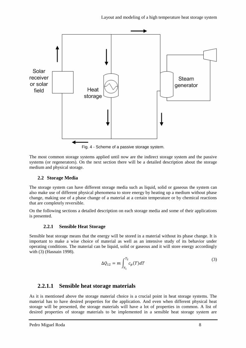
Layout and modeling of a high temperature heat storage system
Pedro Miguel Roda 15
investigations suggest is that a series of PCM is placed in series next to each other where the
phase change temperature is lowering from the left (inlet during charging) to the right (outlet
during charging) this temperature is constant along the whole process and a constant heat flux
is also achieved this approach is usually called cascaded PCM (Jegadheeswaran and Pohekar
2009) Fig 7 shows an example of a cascaded heat storage system
Fig 7 - Example of a cascaded latent heat storage system (Michels and Pitz-Paal 2007)
Experimental investigations with three PCMs sodium nitrate NANO3 a eutectic mixture of
potassium nitrate and potassium chloride KNO3KCl and potassium nitrate KNO3 were
carried out by (Michels and Pitz-Paal 2007)
Michels and Pitz-Paal (2007) work show that when this approach is used a bigger amount of
PCM changes its phase when compared with systems that only use a single PCM they
determined that when using the cascaded approach the PCM material that experiments a phase
change is around 92 during charging process and 67 during discharging process Even
when using a single PCM that the whole material experiences a phase change during charging
process during discharging process only 2 of the material experiences a phase change
Lithium carbonate Li2CO3 prototype
This prototype uses Lithium carbonate Li2CO3 as PCM material and makes uses of copper to
improve the thermal performance of the PCM Verdier Ferriegravere et al (2014) performed
numerical simulations that can be analyzed The system is in equilibrium ate the beginning
and is set on a uniform temperature of 700degC To charge the system a temperature of 900degC is
set as boundary condition on the bottom part of the structure To evaluate the discharging
process of the system a boundary condition of 100degC is set on the bottom of the structure and
before the discharging process begins a uniform temperature of 900degC is assumed for the
system The concept of the system analyzed is showed in Fig 8
Fig 8 - 3D representation of the concept (Verdier Ferriegravere et al 2014)
Layout and modeling of a high temperature heat storage system
Pedro Miguel Roda 16
The numerical results are shown in Fig 9
Fig 9 - Evolution of the PCM temperature during heating (left) and cooling (right) phase (Verdier
Ferriegravere et al 2014)
T1 T3 T5 and T7 are temperatures closer to the fin and T2 T3 T4 and T8 are located in the
center of the compartment
Fig 9 shows the results of the numerical investigations performed by Verdier Ferriegravere et al
(2014) Here a comparison with a system using only PCM without the copper fins was not
made So the only results that can be evaluated is that the system takes around 4h to be
completely charged and 25h to be completely discharged
More investigations and comparisons between traditional latent heat storage systems and system with
the integration of material with high thermal conductivity should be made to really determine its
advantages and influences on the system
223 Thermochemical heat storage
On thermochemical heat storage it is taken advantage of enthalpy but instead of a phase change like in
latent heat storage this system makes use of the completely reversible endothermic chemical
reactions The concept of this system is to absorb the excess heat in an endothermic reaction and store
the products on separate containers During discharging the products are combined exothermically and
the heat of reaction can be used
These systems are far behind in maturity when compared with sensible or latent heat storage systems
but they represent a promising solution due to their high energy density and by the possibility to store
energy at ambient temperature
Like the other systems presented above a proper choice of the materials should be evaluated on the
next section the material choice and properties are presented
2231 Properties of reactions considered for thermochemical energy
storage systems
On thermochemical the properties are related to compounds and reactions On this type of storage
systems the properties chased are even more peculiar and crucial
Necessary properties of the compounds to be used as thermochemical heat storage as told in
Portaspana (2011) work are
Reversibility
No side reactions or changes in reaction rate with the time should occur The reaction should
be completely reversible (Portaspana 2011)
Layout and modeling of a high temperature heat storage system
Pedro Miguel Roda 17
Reaction rates
Both forward and reverse reactions must be rapid enough to absorb all the available energy or
release it promptly The reaction rates must not decrease with cycling Such a decrease can be
observed if structural changes of the storage medium occur (Portaspana 2011)
Controllability
The reactions must be controllable because they have to be turned on and off when required
Controllability is achieved by product separation by controlling the temperature and pressure
or by catalysts (Portaspana 2011)
Ease of storage
The reaction products have to be easily separable prior to storage Reactions must not occur at
storage temperature (Portaspana 2011)
Safety
Toxicity inflammability and corrosiveness of the reaction products may pose unacceptable
safety hazards (Portaspana 2011)
Cost
Cost should be as low as possible which requires materials which are readily available
(Portaspana 2011)
On the following section will be presented some reactions considered for thermochemical heat storage
2232 Examples
Ammonia dissociation
When a thermochemical heat storage system is being implemented it will occur in a reactor
An important detail when evaluating promising reactions is if the process is already well-
known in other applications This is the case of ammonia dissociation reaction (5) the heat
recovering reaction is the well-known Haber Bosch process usually employed for fertilizer
production Ammonia dissociation has other advantages such as no side reactions occur and it
consists of no aggressive reactants for the environment On the other hand ammonia
dissociation has a relatively low enthalpy of reaction around 665 kJmol (Lovegrove Luzzi
et al 1999) Most of the studies on this reaction as a heat storage system have been carried out
by the Australian National University
223
2
3
2
1HNHNH
(5)
Reduction and oxidation reactions
This is a two-step concept that makes use of the principle of transition between the oxidized
and reduced form of an oxide of a metal that has multiple oxidation states (Agrafiotis Roeb et
al 2014)
On the first step an endothermic reaction (6) takes place with the supply of external heat the
reduced state of the oxide MeOox is obtained as a product (Agrafiotis Roeb et al 2014) The
general reaction is
)()( 2 gOMeOHMeO redox (6)
On the second step an exothermic reaction (7) takes place via an oxygen source If air is used
as the oxygen source the oxidation reaction is as the same structure as (Agrafiotis Roeb et al
2014)
Layout and modeling of a high temperature heat storage system
Pedro Miguel Roda 18
)()(2 HMeOgOMeO oxred (7)
Agrafiotis Roeb et al (2014) present the relevant reversible reactions considered for
thermochemical processes as scheme (8) for metal hydroxides scheme (9) for carbonates and
scheme (10) for oxides
reactmolkJHOHCaOHOHCa 100 )()( 22 (8)
reacmolkJHCOCaOHCaCO 167 )( 23 (9)
reacmolkJHOCoOHOCo 200
2
13)( 243
(10)
Heating cycles between 985 and 785degC were performed by Tescari Agrafiotis et al (2014) in
Co3O4 as well as Co3O4 ndash based binary powder metal oxide compositions under air They
showed on their work that the reactions are completely reversible Tescari Agrafiotis et al
(2014) investigated an hybrid system This hybrid system consists of coating a typical
honeycomb sensible heat storage system The investigation suggests that the system will have
a similar behavior to the plain powder thermochemical system and will improve the ceramic
honeycomb system by increasing the amount of energy stored by the system
Cobalt oxide powder was compressed and become a cobalt oxide pellet and was tested by
Karagiannakis Pagkoura et al (2014) Their work shows that the pellet can slightly improve
the performance of the chemical reaction The results for powder and pellet can be seen in Fig
10
Fig 10 - Comparison of thermochemical redox behavior of cobalt oxide in powder and pellet form
(Karagiannakis Pagkoura et al 2014)
In Fig 10 the red line represents the cobalt oxide pellet and the blue line represents the
powder And by analyzing the peaks it is possible to understand that it is possible to operate in
a wider range of temperatures and recover more heat from the reaction
Miguel Gonzalez-Aguilar et al (2014) are on the early investigations for a fluidized bed
system considering the manganese (III) redox reaction showed in (11)
3224332 OMn of 831 46 molkJHOOMnOMn (11)
Sulfur based thermal energy storage
This thermochemical storage concept consists on storing energy by producing elemental sulfur
for later burning To produce elemental sulfur on a thermochemical process three chemical
reactions take place (12) concentrated sulfuric acid is decomposed by heat into water sulfur
dioxide and oxygen (13) sulfur dioxide undergoes disproportionation in water into sulfuric
Layout and modeling of a high temperature heat storage system
Pedro Miguel Roda 19
acid and elemental sulfur (14) the sulfur generated is directed to storage andor to a sulfur
burner for combustion to generate heat The thermochemical cycle does not produce waste
effluent and does not emit greenhouse gas into the environment (Bunsen Wong 2013)
molkJHgSOgOgOHH 97 )(2)()(2(l)SO2H Decomp SO 222 4242 (12)
)((aq)SO2H)(3 O(l)2H ionDisproport 42222 lsSgSOSO (13)
molkJHgOlsSS 297 (g)SO)( )( Combustion 22 (14)
3 Mathematical model
31 Introduction
In this chapter the thermal interaction between the heat transfer fluid and the storage material of the
system is studied mathematically
The system studied is similar to the one installed in the STJ (Zunft Haumlnel et al 2011) using air as
heat transfer fluid and alumina as storage material
The model objective is to simulate a dynamic state of the thermal storage system during charge and
discharge process as well as to switch between these processes in a continuous simulation run This
ability of switching between charging and discharging conditions in one simulation is of crucial
importance in order to enable the complete simulation of the solar methane reforming plant where the
model will be integrated Determining the relation between the total volume of the storage system and
the number of hours that it can provide heat to operate the plant is also a goal of this work
The model discretizes the storage in a large number of interacting layers providing detailed
information about the temperature distribution within the storage Air flows through the honeycomb
bricks channels to transport the heat to or from the storage The convective heat transfer coefficient
between air and solid is sufficiently large which leads to a small temperature difference between air
and solid during charging or discharging of the system
The storage model presented in this work assumes an ideal storage which means that no heat losses
are taken into account during charging or discharging period During standstill period (when air is not
flowing through the channels) the temperature gradient will remain the same until the next charging or
discharging period starts again
The temperature dependent properties of air and the pressure loss by forced convection have been
considered in this model
The storage model is implemented in Aspen Custom Modelerreg with the appropriate syntax shown in
Appendix A - Aspen Custom Modeler Model Code
In order to reduce the computations time only a single channel of one honeycomb brick is simulated
The same conditions are assumed for each parallel channel so that all the channels will have a similar
behavior since no heat losses to environment are considered The energy stored by the system is then
the product of number of channels by the energy stored in only one channel
Layout and modeling of a high temperature heat storage system
Pedro Miguel Roda 20
311 Storage structure
As mentioned in the previous sections the system modeled is similar to the system installed in STJ
The system installed in STJ consists of a storage chamber made of honeycomb storage elements as
shown in Fig 11
The model will only consider the volume of material capable of storing energy which is the volume of
honeycomb bricks excluding the housing and insulation material The model does not consider any
degradation after a long operating period
311 Storage system general properties
The storage installed in STJ is a regenerator-type Air flows from the top to the bottom of the system
in direct contact with the alumina structure during charging period During discharging the air flow is
reversed
The system installed in STJ is a block with a volume of 120m3 and a height of 3m and operates
between 680 and 120degC with a nominal charge mass flow of 94 kgs Table 5 is a summary of the
storage specifications (Zunft Haumlnel et al 2011)
Table 5 - Storage specifications
Storage specifications
Temperature
range
680 ndash 120 degC
Charge mass
flow
94 kgs
Pressure loss lt1500 Pa
The storage material used is alumina porcelain (C130) and its thermophysical properties are shown in
Table 6 (Zunft Haumlnel et al 2011)
Table 6-Alumina porcelain (C130) properties
Honeycombs 60 x 60 channels
Brick dimensions 15 x 15 x 15 cm
Mass density 2700 kgm-3
Specific heat capacity 088kJ(kg-1K-1)
Themal conductivity 21 W(m-1K-1)
Heating surface 1180 m2m-3
Fig 11 - Honeycomb brick
Layout and modeling of a high temperature heat storage system
Pedro Miguel Roda 21
311 Honeycomb storage principle
The principle of the honeycomb ceramic is identical to other sensible heat storage During the
charging period the hot air flows through the systems micro-channels and releases heat increasing the
material temperature During the discharging period the flow direction is reversed and then cold air
flows through the systems micro channels and absorbs the heat stored in the material resulting in an
increase of the air temperature
As Luo Wang et al (2013) showed the honeycomb ceramic have an excellent heat transfer
characteristic resulting from the larger heat exchange area and fine flow behavior meaning relatively
small pressure drop resulting from the flow-through channels
32 Physical model
Fig 12 shows the physical model which consists of a quadrangular channel with length L and opening
s During the charging process heated air flows through the channel from top to bottom of the
channel During the discharging process the air flow is reversed and cold air is pumped from the
bottom to the top of the channel
The channel is discretized in a certain amount of points between 0 and L with the same spacing
between each other The spacing between each point will return more or less accurate results for a
smaller and larger spacing respectively The spacing will also influence the simulation time so a
optimal situation should be determined where a not so time consuming simulation can be carried out
with reasonable accurate results
Fig 12 - Physical model of the storage system
A temperature gradient is achieved during both processes and the system is considered completely
charged when the air temperature in the outlet exceeds the defined minimum temperature that should
usually be defined according to the outlet temperature of the process ie heat exchangers that the heat
is used in In opposite the system is considered completely discharged when the air outlet temperature
during discharge decreases below the required higher temperature level A representative scheme of
the thermal gradient in the system is shown in Fig 13
Layout and modeling of a high temperature heat storage system
Pedro Miguel Roda 22
Fig 13 - Representative thermal gradient in the storage system
33 Governing Equations
The storage system modeled is a regenerator-type heat storage A regenerator is a type of heat
exchanger in which the hot and cold-fluids occupy the same physical space but at different times
Regenerators necessarily operate in a transient mode The temperatures throughout the system depend
upon time as well as on position Partial differential equations are needed to describe the time and
spatial dependence of the temperature of the solid and the fluid These equations can be identified
using energy balances on the fluid and solid (Nellis and Klein)
The energy equations used to describe the model follow the descriptions and assumptions listed below
Ideal behavior of the system the amount of energy recovered is the same as the amount
stored
The fluid flow inside the storage is vertical from top to bottom during charging and from
bottom to top during discharging
The fluid thermophysical properties are temperature and pressure dependent
The solid thermophysical are temperature independent
There is no heat generation or dissipation inside the storage
The system is well insulated and there are no losses to the ambient
Pressure drop along the channel is considered
The system is one dimensional only temperature gradients along the x axis
The energy equation for the fluid (15) is written as
119899119886119894119903 sdot 119888119901119886119894119903 sdot (
120597119879119886119894119903
120597119909) + 120588119886119894119903 sdot 119888119901119886119894119903 sdot 119860119888119904119886119894119903 sdot (
120597119879119886119894119903
120597119905) = 4 sdot 120572 sdot 119904 sdot (119879119886119894119903 minus 119879119904119900119897)
(15)
The first term on the left side of the equation corresponds to the enthalpy associated with the fluid
flow The second term on the left side of the equation corresponds to the rate of change of enthalpy
The term on the right side of the equation corresponds to the heat exchange by convection between the
solid and the fluid The conduction in the fluid can be neglected due to the small value of air
conductivity
The energy equation for the solid (16) is written as
Layout and modeling of a high temperature heat storage system
Pedro Miguel Roda 23
120588119904119900119897 sdot 119888119901119904119900119897 sdot 119860119888119904119904119900119897 sdot (
120597119879119904119900119897
120597119905) = 119860119888119904119904119900119897 sdot 119896119904119900119897 sdot (
1205972119879119904119900119897
1205971199092 ) + 4 sdot 120572 sdot 119904 sdot (119879119886119894119903 minus 119879119904119900119897) (16)
The term on the left side of the equation corresponds to the change of enthalpy of the solid The first
term on the right side of the equation corresponds to the heat transferred by conduction in the solid
along the x axis The second term on the right side corresponds to the heat transferred by convection
between the particles and the fluid
It is necessary to evaluate the convective heat transfer coefficient α to determine the heat transferred
by convection The convective heat transfer coefficient is affected by the state of the flow and the
shape of the duct and can be determined by (17) using the appropriate Nusselt correlation The heat
transfer convective coefficient is determined locally by the model
120572 =
119873119906 sdot 120582119886119894119903
119904
(17)
In order to use the appropriate correlations an evaluation of the flow state is needed this evaluation is
determined by the Reynolds number A flow is laminar if Re le 2400 and turbulent if Re ge 4000 in
between the flow is in a phase called transition (Yunus and Cimbala 2006) In the presented model the
Reynolds number range is from asymp7 ndash 12 meaning that the flow is in laminar phase The appropriate
Nusselt correlation is a correlation that gives the Nusselt number for a fully developed laminar flow
transferring heat to four walls in a quadrangular duct (18) (Shah and London 1978) which depends on
the side length of the duct entry cross section
119873119906 = 8235 [1 minus 20421 sdot 119886 + 30853 sdot 1198862 minus 24765 sdot 1198863 + 10578 sdot 1198864
minus 01861 sdot 1198865]
with 119886 =119888
119889
(18)
119886 represents the relation between the side length of the duct entry cross section and it is equal to one
for quadrangular ducts
331 Boundary and initial conditions
The temperature in the fluid and solid can be determined by (15) and (16) respectively The solution
of the temperatures depends on the physical conditions existing at the boundaries of the system An
initial condition is also needed since the system is also time dependent
The boundary condition to solve the fluid equation (15) is
The air inlet temperature is constant for all time
119879(0 119905) = 119879119886119894119903119894119899 (19)
The boundary conditions to solve the solid equation (16) are
In the first layer of the solid (since there is no previous layer) the conduction is only to the
next layer so the second derivative term becomes a first order derivative term
120588119904119900119897 sdot 119888119901119904119900119897 sdot 119860119888119904119904119900119897 sdot (
120597119879119904119900119897
120597119905) = 119860119888119904119904119900119897 sdot 119896119904119900119897 sdot (
120597119879119904119900119897
120597119909) + 4 sdot 120572 sdot 119904 sdot (119879119886119894119903 minus 119879119904119900119897)
(20)
In last layer of the solid (since there is no next layer) the conduction is only form the previous
layer so the second derivative term becomes a first order derivative term
120588119904119900119897 sdot 119888119901119904119900119897 sdot 119860119888119904119904119900119897 sdot (
120597119879119904119900119897
120597119905) = 119860119888119904119904119900119897 sdot 119896119904119900119897 sdot (
120597119879119904119900119897
120597119909) + 4 sdot 120572 sdot 119904 sdot (119879119886119894119903 minus 119879119904119900119897)
(21)
Layout and modeling of a high temperature heat storage system
Pedro Miguel Roda 24
The initial conditions at the beginning of the simulation are defined by the solid temperature
The system is in equilibrium and the fluid temperature inside the channel is equal to the solid
temperature
119879119886119894119903(119909 0) = 119879119904119900119897(119909 0) (22)
331 Pressure drop
Pressure drop is a quantity of interest since it is directly related to the power requirements of the fan or
pump to maintain flow which will be further considered when the model is implemented in the solar
methane reforming plant model
The pressure drop inside the channel is considered and was determined by (23) from Yunus and
Cimbala (2006)
∆119901 = 119891 sdot
119871
119863sdot
120588119886119894119903 sdot 1198811198861198941199032
2+ 120588119886119894119903 sdot 119892 sdot 119871
(23)
119891 is the Darcy friction factor and it is defined as (24) for fully developed laminar flow in a
quadrangular duct
119891 =
5692
119877119890 119877119890 =
119881119863
120584 119886119899119889 119877119890 le 2300
(24)
331 Energy balance
In order to make sure that the energy gain by the wall during charging process or the energy loss by
the wall during discharging process is the same as the air enthalpy change and make sure that the
model does not violate the first principle of thermodynamics (conservation of energy) two monitoring
variables were created and their values compared
These two variables are the solid enthalpy change determined by (25) and the air enthalpy change
(26)
119876119904119905119908119886119897119897 = 120588119904119900119897 sdot 119888119901119904119900119897 sdot 119860119888119904119904119900119897 sdot 119871 sdot (
120597119879119904119900119897
120597119905)
(25)
119876119886119894119903 = 119899119886119894119903 sdot [ℎ119886119894119903(119871) minus ℎ119886119894119903 (0)] (26)
34 Model Validation
Is necessary to check the model performance with already existing validated models or compare the
model with experimental data In order to compare the model with experimental data it is necessary to
recreate the model as much close to the real system
To validate this model experimental data and previous works from the system installed in STJ are
available (Zunft Haumlnel et al 2011 Kronhardt Alexopoulos et al 2014) To validate the model the
same properties from the system installed in the STJ are implemented in the model
A comparison between the model implemented in Aspen Custom Modeler and a model built in
Comsol Multiphysicsreg will also be shown in this chapter
341 Comparison with experimental data
A test campaign was performed by Zunft Haumlnel et al (2011) in March 2011 These experiments had
the goal to evaluate the storage performance and the validation of existing simulations and design
tools
Layout and modeling of a high temperature heat storage system
Pedro Miguel Roda 25
The experiments include charging period standstill and discharging performance of the storage
system Different inlet air temperatures and different inlet mass flows were tested and measured in the
test campaign The experimental data is not published in detail
The measured data was difficult to interpret and due to lack of information regarding the
thermocouples location it was not possible to achieve the correct interpretation of the measured data
and it was not also possible to establish a comparison between the model presented in this work and
the test campaign performed by Zunft Haumlnel et al (2011)
341 Comparison with previous validated models
The model presented by Hirsch IRT et al (2012) was validated using measured data from the system
installed in STJ The test boundaries as mass flow inlet temperature and inlet pressure are the
nominal solar tower process values showed in Table 5 The initial temperature gradient inside the
system presented by Hirsch IRT et al (2012) was determined by interpolation of the real temperature
of the storage (this initial gradient is not the discharged gradient it is just the reference point before
one hour charging period) Under these conditions this model is appropriate for validation of the
model created in this work
The comparison between the initial gradient in our model and the model by Hirsch IRT et al (2012) is
shown in Fig 14 The results show a good agreement
Fig 14-Initial gradient comparison between aspen model and (Hirsch IRT et al 2012) model
Horizontal axis is normalized
Another comparison is shown in Fig 15 this comparison is the systems profile temperature after one
hour charging Once again the presented model and the model presented by Hirsch IRT et al (2012)
show a good agreement The deviations can be due that in our model a constant inlet mass flow and
inlet temperature is assumed for the whole hour leading to no oscillations Also the difference in the
initial gradient leads to higher deviations between the two models It is expected that when the system
reaches a periodic steady state operating conditions the deviations are reduced
0
100
200
300
400
500
600
700
800
0 011 022 033 044 055 066 077 088 099
Tem
per
ract
ure
[degC
]
System height (normalized)
TAMM
Hirsch IRT et al (2012)
Layout and modeling of a high temperature heat storage system
Pedro Miguel Roda 26
Fig 15 - After one hour charging gradient comparison between Aspen model and (Hirsch IRT et al
2012) model Horizontal axis is normalized
341 Comparison with a Comsol Multiphysicsreg model
The model presented in this work simulates the behavior of one channel of the whole system A
channel of the whole system is a certain number or honeycomb bricks disposed in series on top of each
other until it reaches 3 meter high In our model to achieve the 3 meter height 20 models are connected
in series since every honeycomb brick has 15cm length as shown in Table 6
Aspen Custom Modelerreg is a powerful tool and enables to perform complex calculations and
simulations using a simple syntax and in short period of time Comsol Multiphysicsreg model is also a
powerful tool and also enables the creation of a 3D picture of the system In order to get a better
understanding of the system a simple Comsol Multiphysicsreg model was created
Comsol Multiphysicsreg model
The comsol model consists of a honeycomb channel The alumina properties applied are the same
shown in Table 6 and the air themophysical properties are temperature dependent
The boundary conditions applied in the Comsol model are
Constant inlet temperature of 680ordmC
Adiabatic outer walls of the channel
Constant inlet pressure
Outlet velocity asymp006 ms
The system is in an equilibrium state of 150ordmC in the beginning The system is evaluated after one hour
under these conditions and results are presented in Fig 16
0
100
200
300
400
500
600
700
800
0 011 022 033 044 055 066 077 088 099
Tem
per
ract
ure
[degC
]
System height (normalized)
TAMM
Hirsch IRT et al (2012)
Layout and modeling of a high temperature heat storage system
Pedro Miguel Roda 27
Fig 16 - Comsol results after one hour simulation
When this model is compared with the model created in Aspen that need to be connected in series the
results shown a good agreement with slight deviations The results curves are shown in Fig 17 In Fig
17 Tcomsol corresponds to the Comsol model data TAMM corresponds to the model created in
Aspen where several models are connected in series and TALCM corresponds to the model created in
aspen where a single long channel is simulated
Fig 17 - Comparison with comsol model
341 Comparison between Aspen Models
The model presented in this work shows a good agreement with validated models using measured
data But in order to implement our model in the complete solar methane reforming process model this
connection of blocks is extremely difficult to handle when a transient simulation is carried out due to
the fact that the charging outlet becomes the inlet during discharging of the system In order to
simplify this issue a single model of 3 meter height was created The main difference between a model
of 3m length and 20 models of 15cm length connected in series is that in the 3m length single model
thermal conduction between 2 consecutive bricks occurs
0
100
200
300
400
500
600
700
0 002 004 006 008 01 012 014
Tcomsol
TAMM
TALCM
Layout and modeling of a high temperature heat storage system
Pedro Miguel Roda 28
In order to make sure that thermal conduction between consecutive bricks will not lead to inaccurate
results the two aspen models are compared The curve of the first 15cm of the long channel aspen
model (represents the first brick) is also plotted in Fig 17 In the end of the curve a slight deviation
from the Comsol model and the aspen multiple bricks model can be noticed
Although if the complete systems are compared they show a good agreement here for simplification a
Comsol model is not considered
Regarding the conduction in a long channel can lead to high deviations in low dimensions as shown in
Fig 17 but when compared to the complete system these deviations are negligible as shown in Fig 18
where the series connected model and the single long model in Aspen are compared In Fig 18 the
curves cannot even be distinguished due to superposition
Fig 18 - Comparison between the two different Aspen models
35 Validation discussion
The model created is validated with the previous shown data comparison In order to reduce the
simulation time and the complexity of the system a model of a long single brick will be used to
simulate the system in operation and implemented in the complete solar methane reforming process
model Although this assumption is not completely accurate the deviation from accurate modelling is
small as the validation shows
In the next section a sizing of the system to be implemented will be shown since the solar methane
reforming plant characteristics are different from the STJ
4 System sizing
41 Introduction
In this section a relation between the total volume of the storage material and the solar methane
reforming plant operating hours is presented
As shown in Fig 19 the air is heated up in the solar receiver and pumped to the reformer The solar
methane reforming is designed to operate under constant conditions which means that the air mass
flow and temperature reaching the reformer should be constant during operation The heat storage
system is implemented in parallel to the reformer and the exceeding air during solar radiation period
is used to charge the heat storage system
0
100
200
300
400
500
600
700
800
0 05 1 15 2 25 3
TAMM
TALCM
Layout and modeling of a high temperature heat storage system
Pedro Miguel Roda 29
The charging mass flow to the heat storage system is adjusted enabling a constant air mass flow
delivered to the reformer at a constant temperature of 900 degC
Fig 19 - Solar methane reforming plant with storage scheme
42 Mass flow variation
The air mass flow available at 900 degC depends on the incident solar radiation at a certain time If the
intercept radiation is lower than 15 MWh no air mass flow is available at the desired temperature and
525 MWh is the maximum intercept radiation available
The air mass flow available to the storage system can be determined by (27) The total air mass flow
available varies with the time due to the solar radiation and the air mass flow to the reforming process
is constant
119886119894119903 119905119900 119904119905119900119903119886119892119890 = 119886119894119903 119905119900119905119886119897 minus 119886119894119903 119905119900 119903119890119891119900119903119898119890119903 (27)
Data for the intercept radiation for each hour of the year and the respective air mass flow available for
one channel of the system is evaluated and the first 58 hours correspondences are shown in Appendix
B
43 Energy available
The energy available for storage will be the enthalpy variation of the correspondent air mass flow
available for the storage system during that hour
The outlet temperature of the air after the reforming process is 368 degC and this also corresponds to the
outlet temperature of the heat storage system during charging period The energy available will be the
enthalpy variation of the air from 900 to 368 degC and it is determined by (28)
119905119900119904119905119900119903119886119892119890 = 119886119894119903 119905119900 119904119905119900119903119886119892119890 sdot [ℎ119886119894119903900 minus ℎ119886119894119903368] (28)
Layout and modeling of a high temperature heat storage system
Pedro Miguel Roda 30
A balance for each hour of the year is done (29) During charging period the energy stored is summed
and subtracted if a discharging period is taking place With this energy approach a maximum energy
stored in the system is determined
119876119878119905119900119903119886119892119890(119905 + Δ119905) = 119876119878119905119900119903119886119892119890(119905) + 119905119900119904119905119900119903119886119892119890 sdot Δt (29)
44 Operating hours
The operating hours will vary with the air mass flow designing point of the solar methane reforming
plant
If the air mass flow is set to a low value a higher air mass flow is available to store energy in the
storage system This will enable the solar methane reforming to operate for more hours and the plant
size decreases for a fixed product output when the operating hours are increased In an extreme
scenario the solar methane reforming plant could operate the 8760 hours of one year Although that
the plant could operate the whole year this is not the optimum scenario since the storage volume
required would become huge
45 System volume and shape
The volume of the storage material needed will vary with the operating hours A bigger volume is
needed for more operating hours and a smaller volume is needed for less operating hours
The shape will affect mainly the pressure drop of the system which increases with the length of the
system
Knowing the maximum energy to be stored in the system (determined on the previous point) the
material mass density the material heat capacity and the temperature difference that the system will
operate (in the solar methane reforming plant the temperature range is 900 ndash 368 degC) the storage
material volume needed can be determined by (30)
119881119904119905119900119903119886119892119890 =
119876119905119900119904119905119900119903119886119892119890119898119886119909
120588119904119900119897 sdot 119888119901119904119900119897 sdot ∆119879
(30)
46 System design
With all the information presented in the previous points it is possible to establish a relation between
the operating hours of the solar methane reforming plant and the volume of the storage material This
relation is shown in Fig 20 The maximum of the storage material needed is reached if the plant is
operated continuously for the whole year But this relation is not linear and if the plant is operated for
around 80 of the time the storage material volume needed decreases to around 5 of the maximum
volume needed to operate 100 of the time
Layout and modeling of a high temperature heat storage system
Pedro Miguel Roda 31
Fig 20 - Relation between operating hours of the plant and storage material volume needed Vertical
axis is normalised
The volume needed plotted in Fig 20 does not include housing and insulation material Part of the
material is not heated up (during charging period) or cooled down (during discharging period) because
the temperatures of the outlet cannot exceed the design parameters extra volume should be considered
when the system is implemented in the solar methane reforming plant
461 Reference case
After evaluating the previous results a reference case to simulate the performance of the system should
be set The chosen case is the point immediately before the volume rises exponentially In this case the
plant does not operate for a low number of hours and the system is kept as small as possible The
reference case parameters are shown in Table 7
Table 7 - Reference case parameters
Reference case parameters
Material mass density 2700 [kgm-3]
Material heat capacity 088 [kJ(kg-1K-1)]
Temperature difference 532 [K]
Maximum energy Stored 889 [GJ]
Storage material volume needed 7035 [m3]
Dimensions asymp89times89times89 m
Not operating hours 1785 [h]
When this approach is made it is necessary that the complete volume of the storage material changes
its temperature (form 368 to 900 degC in our application) and that it is no possible since the outlet
temperature of the system cannot rise above the set parameters It is necessary to increase the length of
the system in order to keep the outlet temperature inside its boundaries values
462 Charged and discharged gradients regarding extra length
The extra length needed to the system is determined by running a simulation under an ldquoenergy storedrdquo
condition This condition stops the simulation when the maximum energy stored in the system is
0
01
02
03
04
05
06
07
08
09
1
0 20 40 60 80 100
Vo
lum
e
Operating time
StorageMaterialvolumeneeded
Layout and modeling of a high temperature heat storage system
Pedro Miguel Roda 32
achieved during charging period (to the maximum energy stored value it is summed the value of the
energy stored in the system when it is fully discharged since this energy will not be recovered from
the system in order to guarantee that during discharging period the outlet temperature will not come
below the temperature needed in the process) The simulation is run with a much higher length than
the determined in the reference case When this charged state is achieved the system profile
temperature is evaluated and the outlet is set where the material did not experience any temperature
change This guarantees that when the fully charged condition is achieved the outlet temperature does
not exceed the minimum temperature of the process
After the simulation the total height of the system is determined The dimensions of the system are
showm in
Table 8 - System final dimensions
Reference case parameters
Cross section asymp89times89 m
Height asymp35m
Total volume asymp2772 [m3]
When the system is discharged the outlet temperature of the system cannot go below 900degC In Fig 21
is shown the discharged gradient of the system for the reference case regarding the extra length
needed to fulfill the required outlet temperature
Fig 21 - Reference case discharged temperature gradient considering extra length
When the system is completely charged the outlet temperature of the system cannot rise above 368degC
In Fig 22 is shown the charged gradient of the system for the reference case The outlet during
discharged is located on the left of the x axis (the flow is reversed when charging or discharging)
300
400
500
600
700
800
900
1000
0 5 10 15 20 25 30 35 40
Tem
per
atu
re [
degC]
Systems height [m]
Discharged
Layout and modeling of a high temperature heat storage system
Pedro Miguel Roda 33
Fig 22 - Reference case charged system temperature gradient considering extra length
47 Reference case results
A simulation for the whole year will be carried out for the reference case system An energy balance in
the storage system was determined using an excel sheet and the first 8 hours of this energy balance are
shown in Table 9 When the air to storage is a negative number means that the system is in discharging
period The values presented in Table 9 are results for the whole system
The simulations results and the predicted values show a good agreement with a slight deviation that
can be due to calculations approximation
Table 9 - Simulations results for the first 8 hours of the whole year
Hour Intercepted
Radiation
[MWh]
Air flow to
storage
[kmolh-1]
Energy to storage
[kJh-1]
Energy
accumulated in
the storage [kJ]
Simulation
energy
accumulated
results [kJ]
Error
1 3298 1665099758 2860384958 2860384958 285705133 012
2 4955 475274243 8164479573 1102486453 1101208254 012
3 525 5288722731 9085211188 2011007572 2008675251 012
4 525 5288722731 9085211188 2919528691 2916143713 012
5 525 5288722731 9085211188 382804981 3823613101 012
6 525 5288722731 9085211188 4736570929 4731083209 012
7 41 3216387444 5525258305 5289096759 528296684 012
8 3086 1299706711 2232695974 5512366356 5505977262 012
9 0 29927223 -5028518322 5009514524 5003701682 012
5 Conclusions Energy storage will play a major role in the future of the solar technologies when an energy storage
system is available the utilization of these technologies will increase and will allow solar power to be
produced on demand Energy storage will allow a solar power plant to keep producing energy during
cloudy periods or night period when it is needed the most And will increase the capacity factor of the
plants without fossil fuel backup
300
400
500
600
700
800
900
1000
0 5 10 15 20 25 30 35 40
Tem
per
atu
re [
degC]
Systems height [m]
Charged
Layout and modeling of a high temperature heat storage system
Pedro Miguel Roda 34
The main objective of this work was to model a high temperature heat storage system and predict its
layout in order to overcome the intermittence of the sun as the energy source and to enable the
operation of the plant under constant conditions The type of system chosen to model was a sensible
heat storage system due to the huge amount of information available about these systems
The state of the art in thermal heat storage system is the two tank technology Although that
technology did not fit to the reforming process due to the temperature boundaries related to the two
tanks system
The model was validated using data of previous works that modelled the same system A simulation
for the whole year will be carried out and for the first period of the simulation the results of the
system performance show an excellent agreement with the predicted values The model can be easily
adapted to other applications that want to make use of a sensible heat storage system since the inputs
and dimensions can be easily changed
One major limitation of the model is the neglecting of thermal losses to the environment even if those
losses play a minor role in the system this losses can become an optimization work of the model in a
near future Also the degradation of the material after a long operating period should also be evaluated
in the future since these degradation can lead to thermophysical properties variation of the material
An optimization of the model that can be carried out in the future is the determination of the housing
and insulation material needed to install a complete system
One of the main disadvantages of this system is the huge amount of area required to install it
Investigations in this field should be carried out in the future in order to reduce the volume of the
system
The major advantages of the system are its reliability and the fact that these system are close to other
applications in industry which makes it an already known technology
6 References
Abhat A (1983) Low temperature latent heat thermal energy storage heat storage materials Solar
Energy 30(4) 313-332
Agrafiotis C et al (2014) Exploitation of thermochemical cycles based on solid oxide redox
systems for thermochemical storage of solar heat Part 1 Testing of cobalt oxide-based powders
Solar Energy 102 189-211
Agrafiotis C et al (2014) Solar thermal reforming of methane feedstocks for hydrogen and syngas
productionmdashA review Renewable and Sustainable Energy Reviews 29 656-682
Agrafiotis C et al (2014) Solar thermal reforming of methane feedstocks for hydrogen and syngas
production - A review Renewable and Sustainable Energy Reviews 29 656-682
Bunsen Wong L B Robert Buckingham Dennis Thomey Martin Roeb and Christian sattler (2013)
Sulfur based thermochemical energy storage for concentrated solar power SolarPACES2013
Conference
Caacuterdenas B and N Leoacuten (2013) High temperature latent heat thermal energy storage Phase change
materials design considerations and performance enhancement techniques Renewable and
Sustainable Energy Reviews 27(0) 724-737
Layout and modeling of a high temperature heat storage system
Pedro Miguel Roda 35
Coelho B et al (2010) Solmass projectndashsolar biomass dual hybrid 4 MW CRS pilot plant
SolarPACES Symposium Perpignan
Daschner R et al (2013) Pebble bed regenerator and storage system for high temperature use
Applied Energy 109 394-401
Dunn R I et al (2012) Molten-salt power towers newly commercial concentrating solar storage
Proceedings of the IEEE 100(2) 504-515
European Academies Science Advisory Council (2011) Concentrating Solar Power Its Potential
Contribution to a Sustainable Energy Future EASAC Policy Report 16 EASAC
Gil A et al (2010) State of the art on high temperature thermal energy storage for power
generation Part 1mdashConcepts materials and modellization Renewable and Sustainable Energy
Reviews 14(1) 31-55
Hasnain S (1998) Review on sustainable thermal energy storage technologies Part I heat storage
materials and techniques Energy Conversion and Management 39(11) 1127-1138
Hirsch T et al (2012) DLR Institute for Solar Research (DLR)
Jegadheeswaran S and S D Pohekar (2009) Performance enhancement in latent heat thermal
storage system a review Renewable and Sustainable Energy Reviews 13(9) 2225-2244
Karagiannakis G et al (2014) Monolithic Ceramic Redox Materials for Thermochemical Heat
Storage Applications in CSP Plants Energy Procedia 49 820-829
Khare S et al (2013) Selection of materials for high temperature sensible energy storage Solar
Energy Materials and Solar Cells 115 114-122
Kolb G J (2011) Evaluation of annual performance of 2-tank and thermocline thermal storage
systems for trough plants Journal of Solar Energy Engineering 133(3) 031023
Kronhardt V et al (2014) High-Temperature Thermal Storage System for Solar Tower Power
Plants with Open-Volumetric Air Receiver Simulation and Energy Balancing of a Discretized Model
Energy Procedia 49 870-877
Laing D (2008) Solar thermal energy storage technologies Energy Forum 10000 Solar Gigawatts
23 April 2008
Laing D et al (2012) High-temperature solid-media thermal energy storage for solar thermal power
plants Proceedings of the IEEE 100(2) 516-524
Laing D et al (2008) Solid media thermal storage development and analysis of modular storage
operation concepts for parabolic trough power plants Journal of Solar Energy Engineering 130(1)
011006
Layout and modeling of a high temperature heat storage system
Pedro Miguel Roda 36
Lovegrove K et al (1999) A solar-driven ammonia-based thermochemical energy storage system
Solar Energy 67(4) 309-316
Luo Z et al (2013) Simulation and Experimental Study on Long Term Sensible Thermal Energy
Storage in Solar Thermal System SolarPACES2013
Michels H and R Pitz-Paal (2007) Cascaded latent heat storage for parabolic trough solar power
plants Solar Energy 81(6) 829-837
Miguel S et al (2014) 100-Wh Multi-purpose Particle Reactor for Thermochemical Heat Storage
in Concentrating Solar Power Plants Energy Procedia 49 676-683
Muumlller-Elvers C et al (2012) Design and Construction of Molten Salt Parabolic Trough HPS
Project in Eacutevora Portugal Proc SolarPACES
Muumlller-Steinhagen H and F Trieb (2004) Concentrating solar power A review of the technology
Ingenia Inform QR Acad Eng 18 43-50
Nagl S et al (2011) The economic value of storage in renewable power systems-the case of thermal
energy storage in concentrating solar plants EWI Working Paper
Nellis G and S Klein Heat Transfer Cambridge University Press
Pitz‐Paal R et al (2013) Solar Thermal Power Production Transition to Renewable Energy
Systems 307-338
Portaspana J C (2011) MASTER THESIS High temperature thermal energy storage systems based
on latent and thermo-chemical heat storage Universitaumlt Wien
Shah R K and A L London (1978) Laminar flow forced convection in ducts a source book for
compact heat exchanger analytical data Academic press
Shukla K (1981) Thermal energy storage for solar power generation state of the art Heat Transfer
Engineering 3(2) 62-72
Steinmann W-D and R Tamme (2008) Latent heat storage for solar steam systems Journal of
Solar Energy Engineering 130(1) 011004
Storch H V et al (2014) Investigation of Process Efficiency of an Indirectly Heated Solar
Reformer in M Eden JD Siirola GP Towler (Eds) International Conference on Foundations of
Computer Aided Process Design WAUSA Elsevier
Tescari S et al (2014) Thermochemical Solar Energy Storage Via Redox Oxides Materials and
ReactorHeat Exchanger Concepts Energy Procedia 49 1034-1043
Trieb F et al (2014) Concentrating solar power in a sustainable future electricity mix
Sustainability Science 9(1) 47-60
Layout and modeling of a high temperature heat storage system
Pedro Miguel Roda 37
Tsoutsos T et al (2005) Environmental impacts from the solar energy technologies Energy Policy
33(3) 289-296
Verdier D et al (2014) Experimentation of a High Temperature Thermal Energy Storage Prototype
Using Phase Change Materials for the Thermal Protection of a Pressurized Air Solar Receiver
Energy Procedia 49 1044-1053
Vogel W and H Kalb (April 2010) Large-Scale Solar Thermal Power Technologies Costs and
Development
Yang J et al (2013) Numerical analysis on the thermal behavior of high temperature latent heat
thermal energy storage system Solar Energy 98 543-552
Yunus A C and J M Cimbala (2006) Fluid mechanics fundamentals and applications
International Edition McGraw Hill Publication 185-201
Zunft S et al (2011) Juumllich Solar Power TowermdashExperimental Evaluation of the Storage
Subsystem and Performance Calculation Journal of Solar Energy Engineering 133(3) 031019
Layout and modeling of a high temperature heat storage system
Pedro Miguel Roda 38
Appendix A - Aspen Custom Modeler Model Code
Layout and modeling of a high temperature heat storage system
Pedro Miguel Roda 39
Layout and modeling of a high temperature heat storage system
Pedro Miguel Roda 40
Appendix B - Hourly intercept radiation and correspondent air mass flow
Hour Qic (MHh MHh12000) Hour Qic
(MHh12000)
Hour Qic (MHh MHh12000)
1 3298 19 0 41 0
2 4955 20 0 42 0
3 525 21 0 43 0
4 525 22 0 44 0
5 525 23 0 45 0
6 525 24 802 46 0
7 41 25 3327 47 0
8 3086 26 5213 48 942
9 0 27 525 49 3824
10 0 28 525 50 525
11 0 29 525 51 525
12 0 30 525 52 525
13 0 31 4498 53 5208
14 0 32 2237 54 5108
15 0 33 0 55 4416
16 0 34 0 56 2642
17 0 35 0 57 0
18 0 36 0 58 0
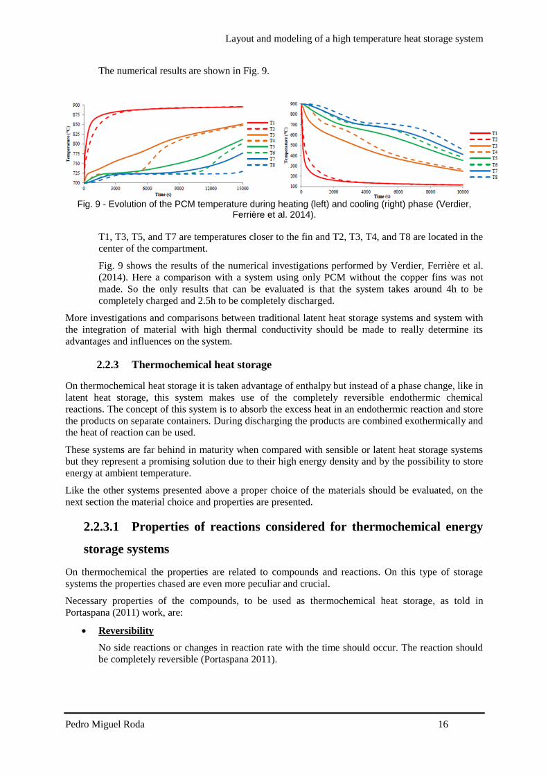
Layout and modeling of a high temperature heat storage system
Pedro Miguel Roda 21
311 Honeycomb storage principle
The principle of the honeycomb ceramic is identical to other sensible heat storage During the
charging period the hot air flows through the systems micro-channels and releases heat increasing the
material temperature During the discharging period the flow direction is reversed and then cold air
flows through the systems micro channels and absorbs the heat stored in the material resulting in an
increase of the air temperature
As Luo Wang et al (2013) showed the honeycomb ceramic have an excellent heat transfer
characteristic resulting from the larger heat exchange area and fine flow behavior meaning relatively
small pressure drop resulting from the flow-through channels
32 Physical model
Fig 12 shows the physical model which consists of a quadrangular channel with length L and opening
s During the charging process heated air flows through the channel from top to bottom of the
channel During the discharging process the air flow is reversed and cold air is pumped from the
bottom to the top of the channel
The channel is discretized in a certain amount of points between 0 and L with the same spacing
between each other The spacing between each point will return more or less accurate results for a
smaller and larger spacing respectively The spacing will also influence the simulation time so a
optimal situation should be determined where a not so time consuming simulation can be carried out
with reasonable accurate results
Fig 12 - Physical model of the storage system
A temperature gradient is achieved during both processes and the system is considered completely
charged when the air temperature in the outlet exceeds the defined minimum temperature that should
usually be defined according to the outlet temperature of the process ie heat exchangers that the heat
is used in In opposite the system is considered completely discharged when the air outlet temperature
during discharge decreases below the required higher temperature level A representative scheme of
the thermal gradient in the system is shown in Fig 13
Layout and modeling of a high temperature heat storage system
Pedro Miguel Roda 22
Fig 13 - Representative thermal gradient in the storage system
33 Governing Equations
The storage system modeled is a regenerator-type heat storage A regenerator is a type of heat
exchanger in which the hot and cold-fluids occupy the same physical space but at different times
Regenerators necessarily operate in a transient mode The temperatures throughout the system depend
upon time as well as on position Partial differential equations are needed to describe the time and
spatial dependence of the temperature of the solid and the fluid These equations can be identified
using energy balances on the fluid and solid (Nellis and Klein)
The energy equations used to describe the model follow the descriptions and assumptions listed below
Ideal behavior of the system the amount of energy recovered is the same as the amount
stored
The fluid flow inside the storage is vertical from top to bottom during charging and from
bottom to top during discharging
The fluid thermophysical properties are temperature and pressure dependent
The solid thermophysical are temperature independent
There is no heat generation or dissipation inside the storage
The system is well insulated and there are no losses to the ambient
Pressure drop along the channel is considered
The system is one dimensional only temperature gradients along the x axis
The energy equation for the fluid (15) is written as
119899119886119894119903 sdot 119888119901119886119894119903 sdot (
120597119879119886119894119903
120597119909) + 120588119886119894119903 sdot 119888119901119886119894119903 sdot 119860119888119904119886119894119903 sdot (
120597119879119886119894119903
120597119905) = 4 sdot 120572 sdot 119904 sdot (119879119886119894119903 minus 119879119904119900119897)
(15)
The first term on the left side of the equation corresponds to the enthalpy associated with the fluid
flow The second term on the left side of the equation corresponds to the rate of change of enthalpy
The term on the right side of the equation corresponds to the heat exchange by convection between the
solid and the fluid The conduction in the fluid can be neglected due to the small value of air
conductivity
The energy equation for the solid (16) is written as
Layout and modeling of a high temperature heat storage system
Pedro Miguel Roda 23
120588119904119900119897 sdot 119888119901119904119900119897 sdot 119860119888119904119904119900119897 sdot (
120597119879119904119900119897
120597119905) = 119860119888119904119904119900119897 sdot 119896119904119900119897 sdot (
1205972119879119904119900119897
1205971199092 ) + 4 sdot 120572 sdot 119904 sdot (119879119886119894119903 minus 119879119904119900119897) (16)
The term on the left side of the equation corresponds to the change of enthalpy of the solid The first
term on the right side of the equation corresponds to the heat transferred by conduction in the solid
along the x axis The second term on the right side corresponds to the heat transferred by convection
between the particles and the fluid
It is necessary to evaluate the convective heat transfer coefficient α to determine the heat transferred
by convection The convective heat transfer coefficient is affected by the state of the flow and the
shape of the duct and can be determined by (17) using the appropriate Nusselt correlation The heat
transfer convective coefficient is determined locally by the model
120572 =
119873119906 sdot 120582119886119894119903
119904
(17)
In order to use the appropriate correlations an evaluation of the flow state is needed this evaluation is
determined by the Reynolds number A flow is laminar if Re le 2400 and turbulent if Re ge 4000 in
between the flow is in a phase called transition (Yunus and Cimbala 2006) In the presented model the
Reynolds number range is from asymp7 ndash 12 meaning that the flow is in laminar phase The appropriate
Nusselt correlation is a correlation that gives the Nusselt number for a fully developed laminar flow
transferring heat to four walls in a quadrangular duct (18) (Shah and London 1978) which depends on
the side length of the duct entry cross section
119873119906 = 8235 [1 minus 20421 sdot 119886 + 30853 sdot 1198862 minus 24765 sdot 1198863 + 10578 sdot 1198864
minus 01861 sdot 1198865]
with 119886 =119888
119889
(18)
119886 represents the relation between the side length of the duct entry cross section and it is equal to one
for quadrangular ducts
331 Boundary and initial conditions
The temperature in the fluid and solid can be determined by (15) and (16) respectively The solution
of the temperatures depends on the physical conditions existing at the boundaries of the system An
initial condition is also needed since the system is also time dependent
The boundary condition to solve the fluid equation (15) is
The air inlet temperature is constant for all time
119879(0 119905) = 119879119886119894119903119894119899 (19)
The boundary conditions to solve the solid equation (16) are
In the first layer of the solid (since there is no previous layer) the conduction is only to the
next layer so the second derivative term becomes a first order derivative term
120588119904119900119897 sdot 119888119901119904119900119897 sdot 119860119888119904119904119900119897 sdot (
120597119879119904119900119897
120597119905) = 119860119888119904119904119900119897 sdot 119896119904119900119897 sdot (
120597119879119904119900119897
120597119909) + 4 sdot 120572 sdot 119904 sdot (119879119886119894119903 minus 119879119904119900119897)
(20)
In last layer of the solid (since there is no next layer) the conduction is only form the previous
layer so the second derivative term becomes a first order derivative term
120588119904119900119897 sdot 119888119901119904119900119897 sdot 119860119888119904119904119900119897 sdot (
120597119879119904119900119897
120597119905) = 119860119888119904119904119900119897 sdot 119896119904119900119897 sdot (
120597119879119904119900119897
120597119909) + 4 sdot 120572 sdot 119904 sdot (119879119886119894119903 minus 119879119904119900119897)
(21)
Layout and modeling of a high temperature heat storage system
Pedro Miguel Roda 24
The initial conditions at the beginning of the simulation are defined by the solid temperature
The system is in equilibrium and the fluid temperature inside the channel is equal to the solid
temperature
119879119886119894119903(119909 0) = 119879119904119900119897(119909 0) (22)
331 Pressure drop
Pressure drop is a quantity of interest since it is directly related to the power requirements of the fan or
pump to maintain flow which will be further considered when the model is implemented in the solar
methane reforming plant model
The pressure drop inside the channel is considered and was determined by (23) from Yunus and
Cimbala (2006)
∆119901 = 119891 sdot
119871
119863sdot
120588119886119894119903 sdot 1198811198861198941199032
2+ 120588119886119894119903 sdot 119892 sdot 119871
(23)
119891 is the Darcy friction factor and it is defined as (24) for fully developed laminar flow in a
quadrangular duct
119891 =
5692
119877119890 119877119890 =
119881119863
120584 119886119899119889 119877119890 le 2300
(24)
331 Energy balance
In order to make sure that the energy gain by the wall during charging process or the energy loss by
the wall during discharging process is the same as the air enthalpy change and make sure that the
model does not violate the first principle of thermodynamics (conservation of energy) two monitoring
variables were created and their values compared
These two variables are the solid enthalpy change determined by (25) and the air enthalpy change
(26)
119876119904119905119908119886119897119897 = 120588119904119900119897 sdot 119888119901119904119900119897 sdot 119860119888119904119904119900119897 sdot 119871 sdot (
120597119879119904119900119897
120597119905)
(25)
119876119886119894119903 = 119899119886119894119903 sdot [ℎ119886119894119903(119871) minus ℎ119886119894119903 (0)] (26)
34 Model Validation
Is necessary to check the model performance with already existing validated models or compare the
model with experimental data In order to compare the model with experimental data it is necessary to
recreate the model as much close to the real system
To validate this model experimental data and previous works from the system installed in STJ are
available (Zunft Haumlnel et al 2011 Kronhardt Alexopoulos et al 2014) To validate the model the
same properties from the system installed in the STJ are implemented in the model
A comparison between the model implemented in Aspen Custom Modeler and a model built in
Comsol Multiphysicsreg will also be shown in this chapter
341 Comparison with experimental data
A test campaign was performed by Zunft Haumlnel et al (2011) in March 2011 These experiments had
the goal to evaluate the storage performance and the validation of existing simulations and design
tools
Layout and modeling of a high temperature heat storage system
Pedro Miguel Roda 25
The experiments include charging period standstill and discharging performance of the storage
system Different inlet air temperatures and different inlet mass flows were tested and measured in the
test campaign The experimental data is not published in detail
The measured data was difficult to interpret and due to lack of information regarding the
thermocouples location it was not possible to achieve the correct interpretation of the measured data
and it was not also possible to establish a comparison between the model presented in this work and
the test campaign performed by Zunft Haumlnel et al (2011)
341 Comparison with previous validated models
The model presented by Hirsch IRT et al (2012) was validated using measured data from the system
installed in STJ The test boundaries as mass flow inlet temperature and inlet pressure are the
nominal solar tower process values showed in Table 5 The initial temperature gradient inside the
system presented by Hirsch IRT et al (2012) was determined by interpolation of the real temperature
of the storage (this initial gradient is not the discharged gradient it is just the reference point before
one hour charging period) Under these conditions this model is appropriate for validation of the
model created in this work
The comparison between the initial gradient in our model and the model by Hirsch IRT et al (2012) is
shown in Fig 14 The results show a good agreement
Fig 14-Initial gradient comparison between aspen model and (Hirsch IRT et al 2012) model
Horizontal axis is normalized
Another comparison is shown in Fig 15 this comparison is the systems profile temperature after one
hour charging Once again the presented model and the model presented by Hirsch IRT et al (2012)
show a good agreement The deviations can be due that in our model a constant inlet mass flow and
inlet temperature is assumed for the whole hour leading to no oscillations Also the difference in the
initial gradient leads to higher deviations between the two models It is expected that when the system
reaches a periodic steady state operating conditions the deviations are reduced
0
100
200
300
400
500
600
700
800
0 011 022 033 044 055 066 077 088 099
Tem
per
ract
ure
[degC
]
System height (normalized)
TAMM
Hirsch IRT et al (2012)
Layout and modeling of a high temperature heat storage system
Pedro Miguel Roda 26
Fig 15 - After one hour charging gradient comparison between Aspen model and (Hirsch IRT et al
2012) model Horizontal axis is normalized
341 Comparison with a Comsol Multiphysicsreg model
The model presented in this work simulates the behavior of one channel of the whole system A
channel of the whole system is a certain number or honeycomb bricks disposed in series on top of each
other until it reaches 3 meter high In our model to achieve the 3 meter height 20 models are connected
in series since every honeycomb brick has 15cm length as shown in Table 6
Aspen Custom Modelerreg is a powerful tool and enables to perform complex calculations and
simulations using a simple syntax and in short period of time Comsol Multiphysicsreg model is also a
powerful tool and also enables the creation of a 3D picture of the system In order to get a better
understanding of the system a simple Comsol Multiphysicsreg model was created
Comsol Multiphysicsreg model
The comsol model consists of a honeycomb channel The alumina properties applied are the same
shown in Table 6 and the air themophysical properties are temperature dependent
The boundary conditions applied in the Comsol model are
Constant inlet temperature of 680ordmC
Adiabatic outer walls of the channel
Constant inlet pressure
Outlet velocity asymp006 ms
The system is in an equilibrium state of 150ordmC in the beginning The system is evaluated after one hour
under these conditions and results are presented in Fig 16
0
100
200
300
400
500
600
700
800
0 011 022 033 044 055 066 077 088 099
Tem
per
ract
ure
[degC
]
System height (normalized)
TAMM
Hirsch IRT et al (2012)
Layout and modeling of a high temperature heat storage system
Pedro Miguel Roda 27
Fig 16 - Comsol results after one hour simulation
When this model is compared with the model created in Aspen that need to be connected in series the
results shown a good agreement with slight deviations The results curves are shown in Fig 17 In Fig
17 Tcomsol corresponds to the Comsol model data TAMM corresponds to the model created in
Aspen where several models are connected in series and TALCM corresponds to the model created in
aspen where a single long channel is simulated
Fig 17 - Comparison with comsol model
341 Comparison between Aspen Models
The model presented in this work shows a good agreement with validated models using measured
data But in order to implement our model in the complete solar methane reforming process model this
connection of blocks is extremely difficult to handle when a transient simulation is carried out due to
the fact that the charging outlet becomes the inlet during discharging of the system In order to
simplify this issue a single model of 3 meter height was created The main difference between a model
of 3m length and 20 models of 15cm length connected in series is that in the 3m length single model
thermal conduction between 2 consecutive bricks occurs
0
100
200
300
400
500
600
700
0 002 004 006 008 01 012 014
Tcomsol
TAMM
TALCM
Layout and modeling of a high temperature heat storage system
Pedro Miguel Roda 28
In order to make sure that thermal conduction between consecutive bricks will not lead to inaccurate
results the two aspen models are compared The curve of the first 15cm of the long channel aspen
model (represents the first brick) is also plotted in Fig 17 In the end of the curve a slight deviation
from the Comsol model and the aspen multiple bricks model can be noticed
Although if the complete systems are compared they show a good agreement here for simplification a
Comsol model is not considered
Regarding the conduction in a long channel can lead to high deviations in low dimensions as shown in
Fig 17 but when compared to the complete system these deviations are negligible as shown in Fig 18
where the series connected model and the single long model in Aspen are compared In Fig 18 the
curves cannot even be distinguished due to superposition
Fig 18 - Comparison between the two different Aspen models
35 Validation discussion
The model created is validated with the previous shown data comparison In order to reduce the
simulation time and the complexity of the system a model of a long single brick will be used to
simulate the system in operation and implemented in the complete solar methane reforming process
model Although this assumption is not completely accurate the deviation from accurate modelling is
small as the validation shows
In the next section a sizing of the system to be implemented will be shown since the solar methane
reforming plant characteristics are different from the STJ
4 System sizing
41 Introduction
In this section a relation between the total volume of the storage material and the solar methane
reforming plant operating hours is presented
As shown in Fig 19 the air is heated up in the solar receiver and pumped to the reformer The solar
methane reforming is designed to operate under constant conditions which means that the air mass
flow and temperature reaching the reformer should be constant during operation The heat storage
system is implemented in parallel to the reformer and the exceeding air during solar radiation period
is used to charge the heat storage system
0
100
200
300
400
500
600
700
800
0 05 1 15 2 25 3
TAMM
TALCM
Layout and modeling of a high temperature heat storage system
Pedro Miguel Roda 29
The charging mass flow to the heat storage system is adjusted enabling a constant air mass flow
delivered to the reformer at a constant temperature of 900 degC
Fig 19 - Solar methane reforming plant with storage scheme
42 Mass flow variation
The air mass flow available at 900 degC depends on the incident solar radiation at a certain time If the
intercept radiation is lower than 15 MWh no air mass flow is available at the desired temperature and
525 MWh is the maximum intercept radiation available
The air mass flow available to the storage system can be determined by (27) The total air mass flow
available varies with the time due to the solar radiation and the air mass flow to the reforming process
is constant
119886119894119903 119905119900 119904119905119900119903119886119892119890 = 119886119894119903 119905119900119905119886119897 minus 119886119894119903 119905119900 119903119890119891119900119903119898119890119903 (27)
Data for the intercept radiation for each hour of the year and the respective air mass flow available for
one channel of the system is evaluated and the first 58 hours correspondences are shown in Appendix
B
43 Energy available
The energy available for storage will be the enthalpy variation of the correspondent air mass flow
available for the storage system during that hour
The outlet temperature of the air after the reforming process is 368 degC and this also corresponds to the
outlet temperature of the heat storage system during charging period The energy available will be the
enthalpy variation of the air from 900 to 368 degC and it is determined by (28)
119905119900119904119905119900119903119886119892119890 = 119886119894119903 119905119900 119904119905119900119903119886119892119890 sdot [ℎ119886119894119903900 minus ℎ119886119894119903368] (28)
Layout and modeling of a high temperature heat storage system
Pedro Miguel Roda 30
A balance for each hour of the year is done (29) During charging period the energy stored is summed
and subtracted if a discharging period is taking place With this energy approach a maximum energy
stored in the system is determined
119876119878119905119900119903119886119892119890(119905 + Δ119905) = 119876119878119905119900119903119886119892119890(119905) + 119905119900119904119905119900119903119886119892119890 sdot Δt (29)
44 Operating hours
The operating hours will vary with the air mass flow designing point of the solar methane reforming
plant
If the air mass flow is set to a low value a higher air mass flow is available to store energy in the
storage system This will enable the solar methane reforming to operate for more hours and the plant
size decreases for a fixed product output when the operating hours are increased In an extreme
scenario the solar methane reforming plant could operate the 8760 hours of one year Although that
the plant could operate the whole year this is not the optimum scenario since the storage volume
required would become huge
45 System volume and shape
The volume of the storage material needed will vary with the operating hours A bigger volume is
needed for more operating hours and a smaller volume is needed for less operating hours
The shape will affect mainly the pressure drop of the system which increases with the length of the
system
Knowing the maximum energy to be stored in the system (determined on the previous point) the
material mass density the material heat capacity and the temperature difference that the system will
operate (in the solar methane reforming plant the temperature range is 900 ndash 368 degC) the storage
material volume needed can be determined by (30)
119881119904119905119900119903119886119892119890 =
119876119905119900119904119905119900119903119886119892119890119898119886119909
120588119904119900119897 sdot 119888119901119904119900119897 sdot ∆119879
(30)
46 System design
With all the information presented in the previous points it is possible to establish a relation between
the operating hours of the solar methane reforming plant and the volume of the storage material This
relation is shown in Fig 20 The maximum of the storage material needed is reached if the plant is
operated continuously for the whole year But this relation is not linear and if the plant is operated for
around 80 of the time the storage material volume needed decreases to around 5 of the maximum
volume needed to operate 100 of the time
Layout and modeling of a high temperature heat storage system
Pedro Miguel Roda 31
Fig 20 - Relation between operating hours of the plant and storage material volume needed Vertical
axis is normalised
The volume needed plotted in Fig 20 does not include housing and insulation material Part of the
material is not heated up (during charging period) or cooled down (during discharging period) because
the temperatures of the outlet cannot exceed the design parameters extra volume should be considered
when the system is implemented in the solar methane reforming plant
461 Reference case
After evaluating the previous results a reference case to simulate the performance of the system should
be set The chosen case is the point immediately before the volume rises exponentially In this case the
plant does not operate for a low number of hours and the system is kept as small as possible The
reference case parameters are shown in Table 7
Table 7 - Reference case parameters
Reference case parameters
Material mass density 2700 [kgm-3]
Material heat capacity 088 [kJ(kg-1K-1)]
Temperature difference 532 [K]
Maximum energy Stored 889 [GJ]
Storage material volume needed 7035 [m3]
Dimensions asymp89times89times89 m
Not operating hours 1785 [h]
When this approach is made it is necessary that the complete volume of the storage material changes
its temperature (form 368 to 900 degC in our application) and that it is no possible since the outlet
temperature of the system cannot rise above the set parameters It is necessary to increase the length of
the system in order to keep the outlet temperature inside its boundaries values
462 Charged and discharged gradients regarding extra length
The extra length needed to the system is determined by running a simulation under an ldquoenergy storedrdquo
condition This condition stops the simulation when the maximum energy stored in the system is
0
01
02
03
04
05
06
07
08
09
1
0 20 40 60 80 100
Vo
lum
e
Operating time
StorageMaterialvolumeneeded
Layout and modeling of a high temperature heat storage system
Pedro Miguel Roda 32
achieved during charging period (to the maximum energy stored value it is summed the value of the
energy stored in the system when it is fully discharged since this energy will not be recovered from
the system in order to guarantee that during discharging period the outlet temperature will not come
below the temperature needed in the process) The simulation is run with a much higher length than
the determined in the reference case When this charged state is achieved the system profile
temperature is evaluated and the outlet is set where the material did not experience any temperature
change This guarantees that when the fully charged condition is achieved the outlet temperature does
not exceed the minimum temperature of the process
After the simulation the total height of the system is determined The dimensions of the system are
showm in
Table 8 - System final dimensions
Reference case parameters
Cross section asymp89times89 m
Height asymp35m
Total volume asymp2772 [m3]
When the system is discharged the outlet temperature of the system cannot go below 900degC In Fig 21
is shown the discharged gradient of the system for the reference case regarding the extra length
needed to fulfill the required outlet temperature
Fig 21 - Reference case discharged temperature gradient considering extra length
When the system is completely charged the outlet temperature of the system cannot rise above 368degC
In Fig 22 is shown the charged gradient of the system for the reference case The outlet during
discharged is located on the left of the x axis (the flow is reversed when charging or discharging)
300
400
500
600
700
800
900
1000
0 5 10 15 20 25 30 35 40
Tem
per
atu
re [
degC]
Systems height [m]
Discharged
Layout and modeling of a high temperature heat storage system
Pedro Miguel Roda 33
Fig 22 - Reference case charged system temperature gradient considering extra length
47 Reference case results
A simulation for the whole year will be carried out for the reference case system An energy balance in
the storage system was determined using an excel sheet and the first 8 hours of this energy balance are
shown in Table 9 When the air to storage is a negative number means that the system is in discharging
period The values presented in Table 9 are results for the whole system
The simulations results and the predicted values show a good agreement with a slight deviation that
can be due to calculations approximation
Table 9 - Simulations results for the first 8 hours of the whole year
Hour Intercepted
Radiation
[MWh]
Air flow to
storage
[kmolh-1]
Energy to storage
[kJh-1]
Energy
accumulated in
the storage [kJ]
Simulation
energy
accumulated
results [kJ]
Error
1 3298 1665099758 2860384958 2860384958 285705133 012
2 4955 475274243 8164479573 1102486453 1101208254 012
3 525 5288722731 9085211188 2011007572 2008675251 012
4 525 5288722731 9085211188 2919528691 2916143713 012
5 525 5288722731 9085211188 382804981 3823613101 012
6 525 5288722731 9085211188 4736570929 4731083209 012
7 41 3216387444 5525258305 5289096759 528296684 012
8 3086 1299706711 2232695974 5512366356 5505977262 012
9 0 29927223 -5028518322 5009514524 5003701682 012
5 Conclusions Energy storage will play a major role in the future of the solar technologies when an energy storage
system is available the utilization of these technologies will increase and will allow solar power to be
produced on demand Energy storage will allow a solar power plant to keep producing energy during
cloudy periods or night period when it is needed the most And will increase the capacity factor of the
plants without fossil fuel backup
300
400
500
600
700
800
900
1000
0 5 10 15 20 25 30 35 40
Tem
per
atu
re [
degC]
Systems height [m]
Charged
Layout and modeling of a high temperature heat storage system
Pedro Miguel Roda 34
The main objective of this work was to model a high temperature heat storage system and predict its
layout in order to overcome the intermittence of the sun as the energy source and to enable the
operation of the plant under constant conditions The type of system chosen to model was a sensible
heat storage system due to the huge amount of information available about these systems
The state of the art in thermal heat storage system is the two tank technology Although that
technology did not fit to the reforming process due to the temperature boundaries related to the two
tanks system
The model was validated using data of previous works that modelled the same system A simulation
for the whole year will be carried out and for the first period of the simulation the results of the
system performance show an excellent agreement with the predicted values The model can be easily
adapted to other applications that want to make use of a sensible heat storage system since the inputs
and dimensions can be easily changed
One major limitation of the model is the neglecting of thermal losses to the environment even if those
losses play a minor role in the system this losses can become an optimization work of the model in a
near future Also the degradation of the material after a long operating period should also be evaluated
in the future since these degradation can lead to thermophysical properties variation of the material
An optimization of the model that can be carried out in the future is the determination of the housing
and insulation material needed to install a complete system
One of the main disadvantages of this system is the huge amount of area required to install it
Investigations in this field should be carried out in the future in order to reduce the volume of the
system
The major advantages of the system are its reliability and the fact that these system are close to other
applications in industry which makes it an already known technology
6 References
Abhat A (1983) Low temperature latent heat thermal energy storage heat storage materials Solar
Energy 30(4) 313-332
Agrafiotis C et al (2014) Exploitation of thermochemical cycles based on solid oxide redox
systems for thermochemical storage of solar heat Part 1 Testing of cobalt oxide-based powders
Solar Energy 102 189-211
Agrafiotis C et al (2014) Solar thermal reforming of methane feedstocks for hydrogen and syngas
productionmdashA review Renewable and Sustainable Energy Reviews 29 656-682
Agrafiotis C et al (2014) Solar thermal reforming of methane feedstocks for hydrogen and syngas
production - A review Renewable and Sustainable Energy Reviews 29 656-682
Bunsen Wong L B Robert Buckingham Dennis Thomey Martin Roeb and Christian sattler (2013)
Sulfur based thermochemical energy storage for concentrated solar power SolarPACES2013
Conference
Caacuterdenas B and N Leoacuten (2013) High temperature latent heat thermal energy storage Phase change
materials design considerations and performance enhancement techniques Renewable and
Sustainable Energy Reviews 27(0) 724-737
Layout and modeling of a high temperature heat storage system
Pedro Miguel Roda 35
Coelho B et al (2010) Solmass projectndashsolar biomass dual hybrid 4 MW CRS pilot plant
SolarPACES Symposium Perpignan
Daschner R et al (2013) Pebble bed regenerator and storage system for high temperature use
Applied Energy 109 394-401
Dunn R I et al (2012) Molten-salt power towers newly commercial concentrating solar storage
Proceedings of the IEEE 100(2) 504-515
European Academies Science Advisory Council (2011) Concentrating Solar Power Its Potential
Contribution to a Sustainable Energy Future EASAC Policy Report 16 EASAC
Gil A et al (2010) State of the art on high temperature thermal energy storage for power
generation Part 1mdashConcepts materials and modellization Renewable and Sustainable Energy
Reviews 14(1) 31-55
Hasnain S (1998) Review on sustainable thermal energy storage technologies Part I heat storage
materials and techniques Energy Conversion and Management 39(11) 1127-1138
Hirsch T et al (2012) DLR Institute for Solar Research (DLR)
Jegadheeswaran S and S D Pohekar (2009) Performance enhancement in latent heat thermal
storage system a review Renewable and Sustainable Energy Reviews 13(9) 2225-2244
Karagiannakis G et al (2014) Monolithic Ceramic Redox Materials for Thermochemical Heat
Storage Applications in CSP Plants Energy Procedia 49 820-829
Khare S et al (2013) Selection of materials for high temperature sensible energy storage Solar
Energy Materials and Solar Cells 115 114-122
Kolb G J (2011) Evaluation of annual performance of 2-tank and thermocline thermal storage
systems for trough plants Journal of Solar Energy Engineering 133(3) 031023
Kronhardt V et al (2014) High-Temperature Thermal Storage System for Solar Tower Power
Plants with Open-Volumetric Air Receiver Simulation and Energy Balancing of a Discretized Model
Energy Procedia 49 870-877
Laing D (2008) Solar thermal energy storage technologies Energy Forum 10000 Solar Gigawatts
23 April 2008
Laing D et al (2012) High-temperature solid-media thermal energy storage for solar thermal power
plants Proceedings of the IEEE 100(2) 516-524
Laing D et al (2008) Solid media thermal storage development and analysis of modular storage
operation concepts for parabolic trough power plants Journal of Solar Energy Engineering 130(1)
011006
Layout and modeling of a high temperature heat storage system
Pedro Miguel Roda 36
Lovegrove K et al (1999) A solar-driven ammonia-based thermochemical energy storage system
Solar Energy 67(4) 309-316
Luo Z et al (2013) Simulation and Experimental Study on Long Term Sensible Thermal Energy
Storage in Solar Thermal System SolarPACES2013
Michels H and R Pitz-Paal (2007) Cascaded latent heat storage for parabolic trough solar power
plants Solar Energy 81(6) 829-837
Miguel S et al (2014) 100-Wh Multi-purpose Particle Reactor for Thermochemical Heat Storage
in Concentrating Solar Power Plants Energy Procedia 49 676-683
Muumlller-Elvers C et al (2012) Design and Construction of Molten Salt Parabolic Trough HPS
Project in Eacutevora Portugal Proc SolarPACES
Muumlller-Steinhagen H and F Trieb (2004) Concentrating solar power A review of the technology
Ingenia Inform QR Acad Eng 18 43-50
Nagl S et al (2011) The economic value of storage in renewable power systems-the case of thermal
energy storage in concentrating solar plants EWI Working Paper
Nellis G and S Klein Heat Transfer Cambridge University Press
Pitz‐Paal R et al (2013) Solar Thermal Power Production Transition to Renewable Energy
Systems 307-338
Portaspana J C (2011) MASTER THESIS High temperature thermal energy storage systems based
on latent and thermo-chemical heat storage Universitaumlt Wien
Shah R K and A L London (1978) Laminar flow forced convection in ducts a source book for
compact heat exchanger analytical data Academic press
Shukla K (1981) Thermal energy storage for solar power generation state of the art Heat Transfer
Engineering 3(2) 62-72
Steinmann W-D and R Tamme (2008) Latent heat storage for solar steam systems Journal of
Solar Energy Engineering 130(1) 011004
Storch H V et al (2014) Investigation of Process Efficiency of an Indirectly Heated Solar
Reformer in M Eden JD Siirola GP Towler (Eds) International Conference on Foundations of
Computer Aided Process Design WAUSA Elsevier
Tescari S et al (2014) Thermochemical Solar Energy Storage Via Redox Oxides Materials and
ReactorHeat Exchanger Concepts Energy Procedia 49 1034-1043
Trieb F et al (2014) Concentrating solar power in a sustainable future electricity mix
Sustainability Science 9(1) 47-60
Layout and modeling of a high temperature heat storage system
Pedro Miguel Roda 37
Tsoutsos T et al (2005) Environmental impacts from the solar energy technologies Energy Policy
33(3) 289-296
Verdier D et al (2014) Experimentation of a High Temperature Thermal Energy Storage Prototype
Using Phase Change Materials for the Thermal Protection of a Pressurized Air Solar Receiver
Energy Procedia 49 1044-1053
Vogel W and H Kalb (April 2010) Large-Scale Solar Thermal Power Technologies Costs and
Development
Yang J et al (2013) Numerical analysis on the thermal behavior of high temperature latent heat
thermal energy storage system Solar Energy 98 543-552
Yunus A C and J M Cimbala (2006) Fluid mechanics fundamentals and applications
International Edition McGraw Hill Publication 185-201
Zunft S et al (2011) Juumllich Solar Power TowermdashExperimental Evaluation of the Storage
Subsystem and Performance Calculation Journal of Solar Energy Engineering 133(3) 031019
Layout and modeling of a high temperature heat storage system
Pedro Miguel Roda 38
Appendix A - Aspen Custom Modeler Model Code
Layout and modeling of a high temperature heat storage system
Pedro Miguel Roda 39
Layout and modeling of a high temperature heat storage system
Pedro Miguel Roda 40
Appendix B - Hourly intercept radiation and correspondent air mass flow
Hour Qic (MHh MHh12000) Hour Qic
(MHh12000)
Hour Qic (MHh MHh12000)
1 3298 19 0 41 0
2 4955 20 0 42 0
3 525 21 0 43 0
4 525 22 0 44 0
5 525 23 0 45 0
6 525 24 802 46 0
7 41 25 3327 47 0
8 3086 26 5213 48 942
9 0 27 525 49 3824
10 0 28 525 50 525
11 0 29 525 51 525
12 0 30 525 52 525
13 0 31 4498 53 5208
14 0 32 2237 54 5108
15 0 33 0 55 4416
16 0 34 0 56 2642
17 0 35 0 57 0
18 0 36 0 58 0
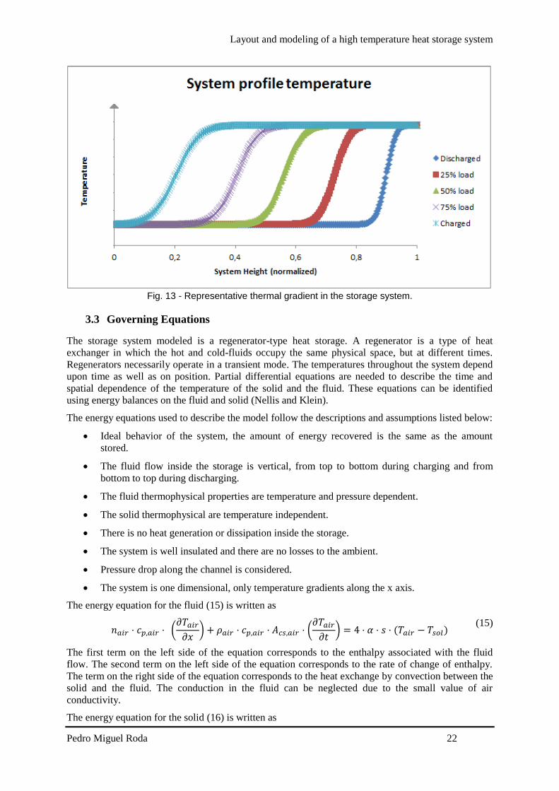
Layout and modeling of a high temperature heat storage system
Pedro Miguel Roda 22
Fig 13 - Representative thermal gradient in the storage system
33 Governing Equations
The storage system modeled is a regenerator-type heat storage A regenerator is a type of heat
exchanger in which the hot and cold-fluids occupy the same physical space but at different times
Regenerators necessarily operate in a transient mode The temperatures throughout the system depend
upon time as well as on position Partial differential equations are needed to describe the time and
spatial dependence of the temperature of the solid and the fluid These equations can be identified
using energy balances on the fluid and solid (Nellis and Klein)
The energy equations used to describe the model follow the descriptions and assumptions listed below
Ideal behavior of the system the amount of energy recovered is the same as the amount
stored
The fluid flow inside the storage is vertical from top to bottom during charging and from
bottom to top during discharging
The fluid thermophysical properties are temperature and pressure dependent
The solid thermophysical are temperature independent
There is no heat generation or dissipation inside the storage
The system is well insulated and there are no losses to the ambient
Pressure drop along the channel is considered
The system is one dimensional only temperature gradients along the x axis
The energy equation for the fluid (15) is written as
119899119886119894119903 sdot 119888119901119886119894119903 sdot (
120597119879119886119894119903
120597119909) + 120588119886119894119903 sdot 119888119901119886119894119903 sdot 119860119888119904119886119894119903 sdot (
120597119879119886119894119903
120597119905) = 4 sdot 120572 sdot 119904 sdot (119879119886119894119903 minus 119879119904119900119897)
(15)
The first term on the left side of the equation corresponds to the enthalpy associated with the fluid
flow The second term on the left side of the equation corresponds to the rate of change of enthalpy
The term on the right side of the equation corresponds to the heat exchange by convection between the
solid and the fluid The conduction in the fluid can be neglected due to the small value of air
conductivity
The energy equation for the solid (16) is written as
Layout and modeling of a high temperature heat storage system
Pedro Miguel Roda 23
120588119904119900119897 sdot 119888119901119904119900119897 sdot 119860119888119904119904119900119897 sdot (
120597119879119904119900119897
120597119905) = 119860119888119904119904119900119897 sdot 119896119904119900119897 sdot (
1205972119879119904119900119897
1205971199092 ) + 4 sdot 120572 sdot 119904 sdot (119879119886119894119903 minus 119879119904119900119897) (16)
The term on the left side of the equation corresponds to the change of enthalpy of the solid The first
term on the right side of the equation corresponds to the heat transferred by conduction in the solid
along the x axis The second term on the right side corresponds to the heat transferred by convection
between the particles and the fluid
It is necessary to evaluate the convective heat transfer coefficient α to determine the heat transferred
by convection The convective heat transfer coefficient is affected by the state of the flow and the
shape of the duct and can be determined by (17) using the appropriate Nusselt correlation The heat
transfer convective coefficient is determined locally by the model
120572 =
119873119906 sdot 120582119886119894119903
119904
(17)
In order to use the appropriate correlations an evaluation of the flow state is needed this evaluation is
determined by the Reynolds number A flow is laminar if Re le 2400 and turbulent if Re ge 4000 in
between the flow is in a phase called transition (Yunus and Cimbala 2006) In the presented model the
Reynolds number range is from asymp7 ndash 12 meaning that the flow is in laminar phase The appropriate
Nusselt correlation is a correlation that gives the Nusselt number for a fully developed laminar flow
transferring heat to four walls in a quadrangular duct (18) (Shah and London 1978) which depends on
the side length of the duct entry cross section
119873119906 = 8235 [1 minus 20421 sdot 119886 + 30853 sdot 1198862 minus 24765 sdot 1198863 + 10578 sdot 1198864
minus 01861 sdot 1198865]
with 119886 =119888
119889
(18)
119886 represents the relation between the side length of the duct entry cross section and it is equal to one
for quadrangular ducts
331 Boundary and initial conditions
The temperature in the fluid and solid can be determined by (15) and (16) respectively The solution
of the temperatures depends on the physical conditions existing at the boundaries of the system An
initial condition is also needed since the system is also time dependent
The boundary condition to solve the fluid equation (15) is
The air inlet temperature is constant for all time
119879(0 119905) = 119879119886119894119903119894119899 (19)
The boundary conditions to solve the solid equation (16) are
In the first layer of the solid (since there is no previous layer) the conduction is only to the
next layer so the second derivative term becomes a first order derivative term
120588119904119900119897 sdot 119888119901119904119900119897 sdot 119860119888119904119904119900119897 sdot (
120597119879119904119900119897
120597119905) = 119860119888119904119904119900119897 sdot 119896119904119900119897 sdot (
120597119879119904119900119897
120597119909) + 4 sdot 120572 sdot 119904 sdot (119879119886119894119903 minus 119879119904119900119897)
(20)
In last layer of the solid (since there is no next layer) the conduction is only form the previous
layer so the second derivative term becomes a first order derivative term
120588119904119900119897 sdot 119888119901119904119900119897 sdot 119860119888119904119904119900119897 sdot (
120597119879119904119900119897
120597119905) = 119860119888119904119904119900119897 sdot 119896119904119900119897 sdot (
120597119879119904119900119897
120597119909) + 4 sdot 120572 sdot 119904 sdot (119879119886119894119903 minus 119879119904119900119897)
(21)
Layout and modeling of a high temperature heat storage system
Pedro Miguel Roda 24
The initial conditions at the beginning of the simulation are defined by the solid temperature
The system is in equilibrium and the fluid temperature inside the channel is equal to the solid
temperature
119879119886119894119903(119909 0) = 119879119904119900119897(119909 0) (22)
331 Pressure drop
Pressure drop is a quantity of interest since it is directly related to the power requirements of the fan or
pump to maintain flow which will be further considered when the model is implemented in the solar
methane reforming plant model
The pressure drop inside the channel is considered and was determined by (23) from Yunus and
Cimbala (2006)
∆119901 = 119891 sdot
119871
119863sdot
120588119886119894119903 sdot 1198811198861198941199032
2+ 120588119886119894119903 sdot 119892 sdot 119871
(23)
119891 is the Darcy friction factor and it is defined as (24) for fully developed laminar flow in a
quadrangular duct
119891 =
5692
119877119890 119877119890 =
119881119863
120584 119886119899119889 119877119890 le 2300
(24)
331 Energy balance
In order to make sure that the energy gain by the wall during charging process or the energy loss by
the wall during discharging process is the same as the air enthalpy change and make sure that the
model does not violate the first principle of thermodynamics (conservation of energy) two monitoring
variables were created and their values compared
These two variables are the solid enthalpy change determined by (25) and the air enthalpy change
(26)
119876119904119905119908119886119897119897 = 120588119904119900119897 sdot 119888119901119904119900119897 sdot 119860119888119904119904119900119897 sdot 119871 sdot (
120597119879119904119900119897
120597119905)
(25)
119876119886119894119903 = 119899119886119894119903 sdot [ℎ119886119894119903(119871) minus ℎ119886119894119903 (0)] (26)
34 Model Validation
Is necessary to check the model performance with already existing validated models or compare the
model with experimental data In order to compare the model with experimental data it is necessary to
recreate the model as much close to the real system
To validate this model experimental data and previous works from the system installed in STJ are
available (Zunft Haumlnel et al 2011 Kronhardt Alexopoulos et al 2014) To validate the model the
same properties from the system installed in the STJ are implemented in the model
A comparison between the model implemented in Aspen Custom Modeler and a model built in
Comsol Multiphysicsreg will also be shown in this chapter
341 Comparison with experimental data
A test campaign was performed by Zunft Haumlnel et al (2011) in March 2011 These experiments had
the goal to evaluate the storage performance and the validation of existing simulations and design
tools
Layout and modeling of a high temperature heat storage system
Pedro Miguel Roda 25
The experiments include charging period standstill and discharging performance of the storage
system Different inlet air temperatures and different inlet mass flows were tested and measured in the
test campaign The experimental data is not published in detail
The measured data was difficult to interpret and due to lack of information regarding the
thermocouples location it was not possible to achieve the correct interpretation of the measured data
and it was not also possible to establish a comparison between the model presented in this work and
the test campaign performed by Zunft Haumlnel et al (2011)
341 Comparison with previous validated models
The model presented by Hirsch IRT et al (2012) was validated using measured data from the system
installed in STJ The test boundaries as mass flow inlet temperature and inlet pressure are the
nominal solar tower process values showed in Table 5 The initial temperature gradient inside the
system presented by Hirsch IRT et al (2012) was determined by interpolation of the real temperature
of the storage (this initial gradient is not the discharged gradient it is just the reference point before
one hour charging period) Under these conditions this model is appropriate for validation of the
model created in this work
The comparison between the initial gradient in our model and the model by Hirsch IRT et al (2012) is
shown in Fig 14 The results show a good agreement
Fig 14-Initial gradient comparison between aspen model and (Hirsch IRT et al 2012) model
Horizontal axis is normalized
Another comparison is shown in Fig 15 this comparison is the systems profile temperature after one
hour charging Once again the presented model and the model presented by Hirsch IRT et al (2012)
show a good agreement The deviations can be due that in our model a constant inlet mass flow and
inlet temperature is assumed for the whole hour leading to no oscillations Also the difference in the
initial gradient leads to higher deviations between the two models It is expected that when the system
reaches a periodic steady state operating conditions the deviations are reduced
0
100
200
300
400
500
600
700
800
0 011 022 033 044 055 066 077 088 099
Tem
per
ract
ure
[degC
]
System height (normalized)
TAMM
Hirsch IRT et al (2012)
Layout and modeling of a high temperature heat storage system
Pedro Miguel Roda 26
Fig 15 - After one hour charging gradient comparison between Aspen model and (Hirsch IRT et al
2012) model Horizontal axis is normalized
341 Comparison with a Comsol Multiphysicsreg model
The model presented in this work simulates the behavior of one channel of the whole system A
channel of the whole system is a certain number or honeycomb bricks disposed in series on top of each
other until it reaches 3 meter high In our model to achieve the 3 meter height 20 models are connected
in series since every honeycomb brick has 15cm length as shown in Table 6
Aspen Custom Modelerreg is a powerful tool and enables to perform complex calculations and
simulations using a simple syntax and in short period of time Comsol Multiphysicsreg model is also a
powerful tool and also enables the creation of a 3D picture of the system In order to get a better
understanding of the system a simple Comsol Multiphysicsreg model was created
Comsol Multiphysicsreg model
The comsol model consists of a honeycomb channel The alumina properties applied are the same
shown in Table 6 and the air themophysical properties are temperature dependent
The boundary conditions applied in the Comsol model are
Constant inlet temperature of 680ordmC
Adiabatic outer walls of the channel
Constant inlet pressure
Outlet velocity asymp006 ms
The system is in an equilibrium state of 150ordmC in the beginning The system is evaluated after one hour
under these conditions and results are presented in Fig 16
0
100
200
300
400
500
600
700
800
0 011 022 033 044 055 066 077 088 099
Tem
per
ract
ure
[degC
]
System height (normalized)
TAMM
Hirsch IRT et al (2012)
Layout and modeling of a high temperature heat storage system
Pedro Miguel Roda 27
Fig 16 - Comsol results after one hour simulation
When this model is compared with the model created in Aspen that need to be connected in series the
results shown a good agreement with slight deviations The results curves are shown in Fig 17 In Fig
17 Tcomsol corresponds to the Comsol model data TAMM corresponds to the model created in
Aspen where several models are connected in series and TALCM corresponds to the model created in
aspen where a single long channel is simulated
Fig 17 - Comparison with comsol model
341 Comparison between Aspen Models
The model presented in this work shows a good agreement with validated models using measured
data But in order to implement our model in the complete solar methane reforming process model this
connection of blocks is extremely difficult to handle when a transient simulation is carried out due to
the fact that the charging outlet becomes the inlet during discharging of the system In order to
simplify this issue a single model of 3 meter height was created The main difference between a model
of 3m length and 20 models of 15cm length connected in series is that in the 3m length single model
thermal conduction between 2 consecutive bricks occurs
0
100
200
300
400
500
600
700
0 002 004 006 008 01 012 014
Tcomsol
TAMM
TALCM
Layout and modeling of a high temperature heat storage system
Pedro Miguel Roda 28
In order to make sure that thermal conduction between consecutive bricks will not lead to inaccurate
results the two aspen models are compared The curve of the first 15cm of the long channel aspen
model (represents the first brick) is also plotted in Fig 17 In the end of the curve a slight deviation
from the Comsol model and the aspen multiple bricks model can be noticed
Although if the complete systems are compared they show a good agreement here for simplification a
Comsol model is not considered
Regarding the conduction in a long channel can lead to high deviations in low dimensions as shown in
Fig 17 but when compared to the complete system these deviations are negligible as shown in Fig 18
where the series connected model and the single long model in Aspen are compared In Fig 18 the
curves cannot even be distinguished due to superposition
Fig 18 - Comparison between the two different Aspen models
35 Validation discussion
The model created is validated with the previous shown data comparison In order to reduce the
simulation time and the complexity of the system a model of a long single brick will be used to
simulate the system in operation and implemented in the complete solar methane reforming process
model Although this assumption is not completely accurate the deviation from accurate modelling is
small as the validation shows
In the next section a sizing of the system to be implemented will be shown since the solar methane
reforming plant characteristics are different from the STJ
4 System sizing
41 Introduction
In this section a relation between the total volume of the storage material and the solar methane
reforming plant operating hours is presented
As shown in Fig 19 the air is heated up in the solar receiver and pumped to the reformer The solar
methane reforming is designed to operate under constant conditions which means that the air mass
flow and temperature reaching the reformer should be constant during operation The heat storage
system is implemented in parallel to the reformer and the exceeding air during solar radiation period
is used to charge the heat storage system
0
100
200
300
400
500
600
700
800
0 05 1 15 2 25 3
TAMM
TALCM
Layout and modeling of a high temperature heat storage system
Pedro Miguel Roda 29
The charging mass flow to the heat storage system is adjusted enabling a constant air mass flow
delivered to the reformer at a constant temperature of 900 degC
Fig 19 - Solar methane reforming plant with storage scheme
42 Mass flow variation
The air mass flow available at 900 degC depends on the incident solar radiation at a certain time If the
intercept radiation is lower than 15 MWh no air mass flow is available at the desired temperature and
525 MWh is the maximum intercept radiation available
The air mass flow available to the storage system can be determined by (27) The total air mass flow
available varies with the time due to the solar radiation and the air mass flow to the reforming process
is constant
119886119894119903 119905119900 119904119905119900119903119886119892119890 = 119886119894119903 119905119900119905119886119897 minus 119886119894119903 119905119900 119903119890119891119900119903119898119890119903 (27)
Data for the intercept radiation for each hour of the year and the respective air mass flow available for
one channel of the system is evaluated and the first 58 hours correspondences are shown in Appendix
B
43 Energy available
The energy available for storage will be the enthalpy variation of the correspondent air mass flow
available for the storage system during that hour
The outlet temperature of the air after the reforming process is 368 degC and this also corresponds to the
outlet temperature of the heat storage system during charging period The energy available will be the
enthalpy variation of the air from 900 to 368 degC and it is determined by (28)
119905119900119904119905119900119903119886119892119890 = 119886119894119903 119905119900 119904119905119900119903119886119892119890 sdot [ℎ119886119894119903900 minus ℎ119886119894119903368] (28)
Layout and modeling of a high temperature heat storage system
Pedro Miguel Roda 30
A balance for each hour of the year is done (29) During charging period the energy stored is summed
and subtracted if a discharging period is taking place With this energy approach a maximum energy
stored in the system is determined
119876119878119905119900119903119886119892119890(119905 + Δ119905) = 119876119878119905119900119903119886119892119890(119905) + 119905119900119904119905119900119903119886119892119890 sdot Δt (29)
44 Operating hours
The operating hours will vary with the air mass flow designing point of the solar methane reforming
plant
If the air mass flow is set to a low value a higher air mass flow is available to store energy in the
storage system This will enable the solar methane reforming to operate for more hours and the plant
size decreases for a fixed product output when the operating hours are increased In an extreme
scenario the solar methane reforming plant could operate the 8760 hours of one year Although that
the plant could operate the whole year this is not the optimum scenario since the storage volume
required would become huge
45 System volume and shape
The volume of the storage material needed will vary with the operating hours A bigger volume is
needed for more operating hours and a smaller volume is needed for less operating hours
The shape will affect mainly the pressure drop of the system which increases with the length of the
system
Knowing the maximum energy to be stored in the system (determined on the previous point) the
material mass density the material heat capacity and the temperature difference that the system will
operate (in the solar methane reforming plant the temperature range is 900 ndash 368 degC) the storage
material volume needed can be determined by (30)
119881119904119905119900119903119886119892119890 =
119876119905119900119904119905119900119903119886119892119890119898119886119909
120588119904119900119897 sdot 119888119901119904119900119897 sdot ∆119879
(30)
46 System design
With all the information presented in the previous points it is possible to establish a relation between
the operating hours of the solar methane reforming plant and the volume of the storage material This
relation is shown in Fig 20 The maximum of the storage material needed is reached if the plant is
operated continuously for the whole year But this relation is not linear and if the plant is operated for
around 80 of the time the storage material volume needed decreases to around 5 of the maximum
volume needed to operate 100 of the time
Layout and modeling of a high temperature heat storage system
Pedro Miguel Roda 31
Fig 20 - Relation between operating hours of the plant and storage material volume needed Vertical
axis is normalised
The volume needed plotted in Fig 20 does not include housing and insulation material Part of the
material is not heated up (during charging period) or cooled down (during discharging period) because
the temperatures of the outlet cannot exceed the design parameters extra volume should be considered
when the system is implemented in the solar methane reforming plant
461 Reference case
After evaluating the previous results a reference case to simulate the performance of the system should
be set The chosen case is the point immediately before the volume rises exponentially In this case the
plant does not operate for a low number of hours and the system is kept as small as possible The
reference case parameters are shown in Table 7
Table 7 - Reference case parameters
Reference case parameters
Material mass density 2700 [kgm-3]
Material heat capacity 088 [kJ(kg-1K-1)]
Temperature difference 532 [K]
Maximum energy Stored 889 [GJ]
Storage material volume needed 7035 [m3]
Dimensions asymp89times89times89 m
Not operating hours 1785 [h]
When this approach is made it is necessary that the complete volume of the storage material changes
its temperature (form 368 to 900 degC in our application) and that it is no possible since the outlet
temperature of the system cannot rise above the set parameters It is necessary to increase the length of
the system in order to keep the outlet temperature inside its boundaries values
462 Charged and discharged gradients regarding extra length
The extra length needed to the system is determined by running a simulation under an ldquoenergy storedrdquo
condition This condition stops the simulation when the maximum energy stored in the system is
0
01
02
03
04
05
06
07
08
09
1
0 20 40 60 80 100
Vo
lum
e
Operating time
StorageMaterialvolumeneeded
Layout and modeling of a high temperature heat storage system
Pedro Miguel Roda 32
achieved during charging period (to the maximum energy stored value it is summed the value of the
energy stored in the system when it is fully discharged since this energy will not be recovered from
the system in order to guarantee that during discharging period the outlet temperature will not come
below the temperature needed in the process) The simulation is run with a much higher length than
the determined in the reference case When this charged state is achieved the system profile
temperature is evaluated and the outlet is set where the material did not experience any temperature
change This guarantees that when the fully charged condition is achieved the outlet temperature does
not exceed the minimum temperature of the process
After the simulation the total height of the system is determined The dimensions of the system are
showm in
Table 8 - System final dimensions
Reference case parameters
Cross section asymp89times89 m
Height asymp35m
Total volume asymp2772 [m3]
When the system is discharged the outlet temperature of the system cannot go below 900degC In Fig 21
is shown the discharged gradient of the system for the reference case regarding the extra length
needed to fulfill the required outlet temperature
Fig 21 - Reference case discharged temperature gradient considering extra length
When the system is completely charged the outlet temperature of the system cannot rise above 368degC
In Fig 22 is shown the charged gradient of the system for the reference case The outlet during
discharged is located on the left of the x axis (the flow is reversed when charging or discharging)
300
400
500
600
700
800
900
1000
0 5 10 15 20 25 30 35 40
Tem
per
atu
re [
degC]
Systems height [m]
Discharged
Layout and modeling of a high temperature heat storage system
Pedro Miguel Roda 33
Fig 22 - Reference case charged system temperature gradient considering extra length
47 Reference case results
A simulation for the whole year will be carried out for the reference case system An energy balance in
the storage system was determined using an excel sheet and the first 8 hours of this energy balance are
shown in Table 9 When the air to storage is a negative number means that the system is in discharging
period The values presented in Table 9 are results for the whole system
The simulations results and the predicted values show a good agreement with a slight deviation that
can be due to calculations approximation
Table 9 - Simulations results for the first 8 hours of the whole year
Hour Intercepted
Radiation
[MWh]
Air flow to
storage
[kmolh-1]
Energy to storage
[kJh-1]
Energy
accumulated in
the storage [kJ]
Simulation
energy
accumulated
results [kJ]
Error
1 3298 1665099758 2860384958 2860384958 285705133 012
2 4955 475274243 8164479573 1102486453 1101208254 012
3 525 5288722731 9085211188 2011007572 2008675251 012
4 525 5288722731 9085211188 2919528691 2916143713 012
5 525 5288722731 9085211188 382804981 3823613101 012
6 525 5288722731 9085211188 4736570929 4731083209 012
7 41 3216387444 5525258305 5289096759 528296684 012
8 3086 1299706711 2232695974 5512366356 5505977262 012
9 0 29927223 -5028518322 5009514524 5003701682 012
5 Conclusions Energy storage will play a major role in the future of the solar technologies when an energy storage
system is available the utilization of these technologies will increase and will allow solar power to be
produced on demand Energy storage will allow a solar power plant to keep producing energy during
cloudy periods or night period when it is needed the most And will increase the capacity factor of the
plants without fossil fuel backup
300
400
500
600
700
800
900
1000
0 5 10 15 20 25 30 35 40
Tem
per
atu
re [
degC]
Systems height [m]
Charged
Layout and modeling of a high temperature heat storage system
Pedro Miguel Roda 34
The main objective of this work was to model a high temperature heat storage system and predict its
layout in order to overcome the intermittence of the sun as the energy source and to enable the
operation of the plant under constant conditions The type of system chosen to model was a sensible
heat storage system due to the huge amount of information available about these systems
The state of the art in thermal heat storage system is the two tank technology Although that
technology did not fit to the reforming process due to the temperature boundaries related to the two
tanks system
The model was validated using data of previous works that modelled the same system A simulation
for the whole year will be carried out and for the first period of the simulation the results of the
system performance show an excellent agreement with the predicted values The model can be easily
adapted to other applications that want to make use of a sensible heat storage system since the inputs
and dimensions can be easily changed
One major limitation of the model is the neglecting of thermal losses to the environment even if those
losses play a minor role in the system this losses can become an optimization work of the model in a
near future Also the degradation of the material after a long operating period should also be evaluated
in the future since these degradation can lead to thermophysical properties variation of the material
An optimization of the model that can be carried out in the future is the determination of the housing
and insulation material needed to install a complete system
One of the main disadvantages of this system is the huge amount of area required to install it
Investigations in this field should be carried out in the future in order to reduce the volume of the
system
The major advantages of the system are its reliability and the fact that these system are close to other
applications in industry which makes it an already known technology
6 References
Abhat A (1983) Low temperature latent heat thermal energy storage heat storage materials Solar
Energy 30(4) 313-332
Agrafiotis C et al (2014) Exploitation of thermochemical cycles based on solid oxide redox
systems for thermochemical storage of solar heat Part 1 Testing of cobalt oxide-based powders
Solar Energy 102 189-211
Agrafiotis C et al (2014) Solar thermal reforming of methane feedstocks for hydrogen and syngas
productionmdashA review Renewable and Sustainable Energy Reviews 29 656-682
Agrafiotis C et al (2014) Solar thermal reforming of methane feedstocks for hydrogen and syngas
production - A review Renewable and Sustainable Energy Reviews 29 656-682
Bunsen Wong L B Robert Buckingham Dennis Thomey Martin Roeb and Christian sattler (2013)
Sulfur based thermochemical energy storage for concentrated solar power SolarPACES2013
Conference
Caacuterdenas B and N Leoacuten (2013) High temperature latent heat thermal energy storage Phase change
materials design considerations and performance enhancement techniques Renewable and
Sustainable Energy Reviews 27(0) 724-737
Layout and modeling of a high temperature heat storage system
Pedro Miguel Roda 35
Coelho B et al (2010) Solmass projectndashsolar biomass dual hybrid 4 MW CRS pilot plant
SolarPACES Symposium Perpignan
Daschner R et al (2013) Pebble bed regenerator and storage system for high temperature use
Applied Energy 109 394-401
Dunn R I et al (2012) Molten-salt power towers newly commercial concentrating solar storage
Proceedings of the IEEE 100(2) 504-515
European Academies Science Advisory Council (2011) Concentrating Solar Power Its Potential
Contribution to a Sustainable Energy Future EASAC Policy Report 16 EASAC
Gil A et al (2010) State of the art on high temperature thermal energy storage for power
generation Part 1mdashConcepts materials and modellization Renewable and Sustainable Energy
Reviews 14(1) 31-55
Hasnain S (1998) Review on sustainable thermal energy storage technologies Part I heat storage
materials and techniques Energy Conversion and Management 39(11) 1127-1138
Hirsch T et al (2012) DLR Institute for Solar Research (DLR)
Jegadheeswaran S and S D Pohekar (2009) Performance enhancement in latent heat thermal
storage system a review Renewable and Sustainable Energy Reviews 13(9) 2225-2244
Karagiannakis G et al (2014) Monolithic Ceramic Redox Materials for Thermochemical Heat
Storage Applications in CSP Plants Energy Procedia 49 820-829
Khare S et al (2013) Selection of materials for high temperature sensible energy storage Solar
Energy Materials and Solar Cells 115 114-122
Kolb G J (2011) Evaluation of annual performance of 2-tank and thermocline thermal storage
systems for trough plants Journal of Solar Energy Engineering 133(3) 031023
Kronhardt V et al (2014) High-Temperature Thermal Storage System for Solar Tower Power
Plants with Open-Volumetric Air Receiver Simulation and Energy Balancing of a Discretized Model
Energy Procedia 49 870-877
Laing D (2008) Solar thermal energy storage technologies Energy Forum 10000 Solar Gigawatts
23 April 2008
Laing D et al (2012) High-temperature solid-media thermal energy storage for solar thermal power
plants Proceedings of the IEEE 100(2) 516-524
Laing D et al (2008) Solid media thermal storage development and analysis of modular storage
operation concepts for parabolic trough power plants Journal of Solar Energy Engineering 130(1)
011006
Layout and modeling of a high temperature heat storage system
Pedro Miguel Roda 36
Lovegrove K et al (1999) A solar-driven ammonia-based thermochemical energy storage system
Solar Energy 67(4) 309-316
Luo Z et al (2013) Simulation and Experimental Study on Long Term Sensible Thermal Energy
Storage in Solar Thermal System SolarPACES2013
Michels H and R Pitz-Paal (2007) Cascaded latent heat storage for parabolic trough solar power
plants Solar Energy 81(6) 829-837
Miguel S et al (2014) 100-Wh Multi-purpose Particle Reactor for Thermochemical Heat Storage
in Concentrating Solar Power Plants Energy Procedia 49 676-683
Muumlller-Elvers C et al (2012) Design and Construction of Molten Salt Parabolic Trough HPS
Project in Eacutevora Portugal Proc SolarPACES
Muumlller-Steinhagen H and F Trieb (2004) Concentrating solar power A review of the technology
Ingenia Inform QR Acad Eng 18 43-50
Nagl S et al (2011) The economic value of storage in renewable power systems-the case of thermal
energy storage in concentrating solar plants EWI Working Paper
Nellis G and S Klein Heat Transfer Cambridge University Press
Pitz‐Paal R et al (2013) Solar Thermal Power Production Transition to Renewable Energy
Systems 307-338
Portaspana J C (2011) MASTER THESIS High temperature thermal energy storage systems based
on latent and thermo-chemical heat storage Universitaumlt Wien
Shah R K and A L London (1978) Laminar flow forced convection in ducts a source book for
compact heat exchanger analytical data Academic press
Shukla K (1981) Thermal energy storage for solar power generation state of the art Heat Transfer
Engineering 3(2) 62-72
Steinmann W-D and R Tamme (2008) Latent heat storage for solar steam systems Journal of
Solar Energy Engineering 130(1) 011004
Storch H V et al (2014) Investigation of Process Efficiency of an Indirectly Heated Solar
Reformer in M Eden JD Siirola GP Towler (Eds) International Conference on Foundations of
Computer Aided Process Design WAUSA Elsevier
Tescari S et al (2014) Thermochemical Solar Energy Storage Via Redox Oxides Materials and
ReactorHeat Exchanger Concepts Energy Procedia 49 1034-1043
Trieb F et al (2014) Concentrating solar power in a sustainable future electricity mix
Sustainability Science 9(1) 47-60
Layout and modeling of a high temperature heat storage system
Pedro Miguel Roda 37
Tsoutsos T et al (2005) Environmental impacts from the solar energy technologies Energy Policy
33(3) 289-296
Verdier D et al (2014) Experimentation of a High Temperature Thermal Energy Storage Prototype
Using Phase Change Materials for the Thermal Protection of a Pressurized Air Solar Receiver
Energy Procedia 49 1044-1053
Vogel W and H Kalb (April 2010) Large-Scale Solar Thermal Power Technologies Costs and
Development
Yang J et al (2013) Numerical analysis on the thermal behavior of high temperature latent heat
thermal energy storage system Solar Energy 98 543-552
Yunus A C and J M Cimbala (2006) Fluid mechanics fundamentals and applications
International Edition McGraw Hill Publication 185-201
Zunft S et al (2011) Juumllich Solar Power TowermdashExperimental Evaluation of the Storage
Subsystem and Performance Calculation Journal of Solar Energy Engineering 133(3) 031019
Layout and modeling of a high temperature heat storage system
Pedro Miguel Roda 38
Appendix A - Aspen Custom Modeler Model Code
Layout and modeling of a high temperature heat storage system
Pedro Miguel Roda 39
Layout and modeling of a high temperature heat storage system
Pedro Miguel Roda 40
Appendix B - Hourly intercept radiation and correspondent air mass flow
Hour Qic (MHh MHh12000) Hour Qic
(MHh12000)
Hour Qic (MHh MHh12000)
1 3298 19 0 41 0
2 4955 20 0 42 0
3 525 21 0 43 0
4 525 22 0 44 0
5 525 23 0 45 0
6 525 24 802 46 0
7 41 25 3327 47 0
8 3086 26 5213 48 942
9 0 27 525 49 3824
10 0 28 525 50 525
11 0 29 525 51 525
12 0 30 525 52 525
13 0 31 4498 53 5208
14 0 32 2237 54 5108
15 0 33 0 55 4416
16 0 34 0 56 2642
17 0 35 0 57 0
18 0 36 0 58 0
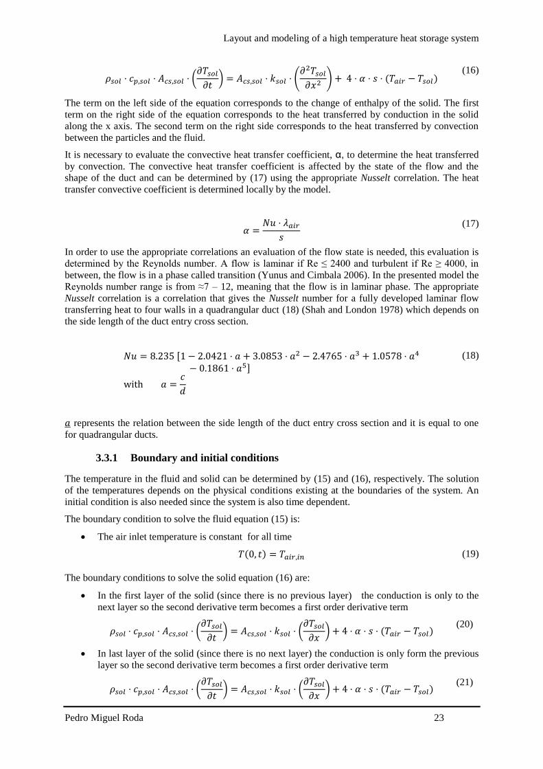
Layout and modeling of a high temperature heat storage system
Pedro Miguel Roda 33
Fig 22 - Reference case charged system temperature gradient considering extra length
47 Reference case results
A simulation for the whole year will be carried out for the reference case system An energy balance in
the storage system was determined using an excel sheet and the first 8 hours of this energy balance are
shown in Table 9 When the air to storage is a negative number means that the system is in discharging
period The values presented in Table 9 are results for the whole system
The simulations results and the predicted values show a good agreement with a slight deviation that
can be due to calculations approximation
Table 9 - Simulations results for the first 8 hours of the whole year
Hour Intercepted
Radiation
[MWh]
Air flow to
storage
[kmolh-1]
Energy to storage
[kJh-1]
Energy
accumulated in
the storage [kJ]
Simulation
energy
accumulated
results [kJ]
Error
1 3298 1665099758 2860384958 2860384958 285705133 012
2 4955 475274243 8164479573 1102486453 1101208254 012
3 525 5288722731 9085211188 2011007572 2008675251 012
4 525 5288722731 9085211188 2919528691 2916143713 012
5 525 5288722731 9085211188 382804981 3823613101 012
6 525 5288722731 9085211188 4736570929 4731083209 012
7 41 3216387444 5525258305 5289096759 528296684 012
8 3086 1299706711 2232695974 5512366356 5505977262 012
9 0 29927223 -5028518322 5009514524 5003701682 012
5 Conclusions Energy storage will play a major role in the future of the solar technologies when an energy storage
system is available the utilization of these technologies will increase and will allow solar power to be
produced on demand Energy storage will allow a solar power plant to keep producing energy during
cloudy periods or night period when it is needed the most And will increase the capacity factor of the
plants without fossil fuel backup
300
400
500
600
700
800
900
1000
0 5 10 15 20 25 30 35 40
Tem
per
atu
re [
degC]
Systems height [m]
Charged
Layout and modeling of a high temperature heat storage system
Pedro Miguel Roda 34
The main objective of this work was to model a high temperature heat storage system and predict its
layout in order to overcome the intermittence of the sun as the energy source and to enable the
operation of the plant under constant conditions The type of system chosen to model was a sensible
heat storage system due to the huge amount of information available about these systems
The state of the art in thermal heat storage system is the two tank technology Although that
technology did not fit to the reforming process due to the temperature boundaries related to the two
tanks system
The model was validated using data of previous works that modelled the same system A simulation
for the whole year will be carried out and for the first period of the simulation the results of the
system performance show an excellent agreement with the predicted values The model can be easily
adapted to other applications that want to make use of a sensible heat storage system since the inputs
and dimensions can be easily changed
One major limitation of the model is the neglecting of thermal losses to the environment even if those
losses play a minor role in the system this losses can become an optimization work of the model in a
near future Also the degradation of the material after a long operating period should also be evaluated
in the future since these degradation can lead to thermophysical properties variation of the material
An optimization of the model that can be carried out in the future is the determination of the housing
and insulation material needed to install a complete system
One of the main disadvantages of this system is the huge amount of area required to install it
Investigations in this field should be carried out in the future in order to reduce the volume of the
system
The major advantages of the system are its reliability and the fact that these system are close to other
applications in industry which makes it an already known technology
6 References
Abhat A (1983) Low temperature latent heat thermal energy storage heat storage materials Solar
Energy 30(4) 313-332
Agrafiotis C et al (2014) Exploitation of thermochemical cycles based on solid oxide redox
systems for thermochemical storage of solar heat Part 1 Testing of cobalt oxide-based powders
Solar Energy 102 189-211
Agrafiotis C et al (2014) Solar thermal reforming of methane feedstocks for hydrogen and syngas
productionmdashA review Renewable and Sustainable Energy Reviews 29 656-682
Agrafiotis C et al (2014) Solar thermal reforming of methane feedstocks for hydrogen and syngas
production - A review Renewable and Sustainable Energy Reviews 29 656-682
Bunsen Wong L B Robert Buckingham Dennis Thomey Martin Roeb and Christian sattler (2013)
Sulfur based thermochemical energy storage for concentrated solar power SolarPACES2013
Conference
Caacuterdenas B and N Leoacuten (2013) High temperature latent heat thermal energy storage Phase change
materials design considerations and performance enhancement techniques Renewable and
Sustainable Energy Reviews 27(0) 724-737
Layout and modeling of a high temperature heat storage system
Pedro Miguel Roda 35
Coelho B et al (2010) Solmass projectndashsolar biomass dual hybrid 4 MW CRS pilot plant
SolarPACES Symposium Perpignan
Daschner R et al (2013) Pebble bed regenerator and storage system for high temperature use
Applied Energy 109 394-401
Dunn R I et al (2012) Molten-salt power towers newly commercial concentrating solar storage
Proceedings of the IEEE 100(2) 504-515
European Academies Science Advisory Council (2011) Concentrating Solar Power Its Potential
Contribution to a Sustainable Energy Future EASAC Policy Report 16 EASAC
Gil A et al (2010) State of the art on high temperature thermal energy storage for power
generation Part 1mdashConcepts materials and modellization Renewable and Sustainable Energy
Reviews 14(1) 31-55
Hasnain S (1998) Review on sustainable thermal energy storage technologies Part I heat storage
materials and techniques Energy Conversion and Management 39(11) 1127-1138
Hirsch T et al (2012) DLR Institute for Solar Research (DLR)
Jegadheeswaran S and S D Pohekar (2009) Performance enhancement in latent heat thermal
storage system a review Renewable and Sustainable Energy Reviews 13(9) 2225-2244
Karagiannakis G et al (2014) Monolithic Ceramic Redox Materials for Thermochemical Heat
Storage Applications in CSP Plants Energy Procedia 49 820-829
Khare S et al (2013) Selection of materials for high temperature sensible energy storage Solar
Energy Materials and Solar Cells 115 114-122
Kolb G J (2011) Evaluation of annual performance of 2-tank and thermocline thermal storage
systems for trough plants Journal of Solar Energy Engineering 133(3) 031023
Kronhardt V et al (2014) High-Temperature Thermal Storage System for Solar Tower Power
Plants with Open-Volumetric Air Receiver Simulation and Energy Balancing of a Discretized Model
Energy Procedia 49 870-877
Laing D (2008) Solar thermal energy storage technologies Energy Forum 10000 Solar Gigawatts
23 April 2008
Laing D et al (2012) High-temperature solid-media thermal energy storage for solar thermal power
plants Proceedings of the IEEE 100(2) 516-524
Laing D et al (2008) Solid media thermal storage development and analysis of modular storage
operation concepts for parabolic trough power plants Journal of Solar Energy Engineering 130(1)
011006
Layout and modeling of a high temperature heat storage system
Pedro Miguel Roda 36
Lovegrove K et al (1999) A solar-driven ammonia-based thermochemical energy storage system
Solar Energy 67(4) 309-316
Luo Z et al (2013) Simulation and Experimental Study on Long Term Sensible Thermal Energy
Storage in Solar Thermal System SolarPACES2013
Michels H and R Pitz-Paal (2007) Cascaded latent heat storage for parabolic trough solar power
plants Solar Energy 81(6) 829-837
Miguel S et al (2014) 100-Wh Multi-purpose Particle Reactor for Thermochemical Heat Storage
in Concentrating Solar Power Plants Energy Procedia 49 676-683
Muumlller-Elvers C et al (2012) Design and Construction of Molten Salt Parabolic Trough HPS
Project in Eacutevora Portugal Proc SolarPACES
Muumlller-Steinhagen H and F Trieb (2004) Concentrating solar power A review of the technology
Ingenia Inform QR Acad Eng 18 43-50
Nagl S et al (2011) The economic value of storage in renewable power systems-the case of thermal
energy storage in concentrating solar plants EWI Working Paper
Nellis G and S Klein Heat Transfer Cambridge University Press
Pitz‐Paal R et al (2013) Solar Thermal Power Production Transition to Renewable Energy
Systems 307-338
Portaspana J C (2011) MASTER THESIS High temperature thermal energy storage systems based
on latent and thermo-chemical heat storage Universitaumlt Wien
Shah R K and A L London (1978) Laminar flow forced convection in ducts a source book for
compact heat exchanger analytical data Academic press
Shukla K (1981) Thermal energy storage for solar power generation state of the art Heat Transfer
Engineering 3(2) 62-72
Steinmann W-D and R Tamme (2008) Latent heat storage for solar steam systems Journal of
Solar Energy Engineering 130(1) 011004
Storch H V et al (2014) Investigation of Process Efficiency of an Indirectly Heated Solar
Reformer in M Eden JD Siirola GP Towler (Eds) International Conference on Foundations of
Computer Aided Process Design WAUSA Elsevier
Tescari S et al (2014) Thermochemical Solar Energy Storage Via Redox Oxides Materials and
ReactorHeat Exchanger Concepts Energy Procedia 49 1034-1043
Trieb F et al (2014) Concentrating solar power in a sustainable future electricity mix
Sustainability Science 9(1) 47-60
Layout and modeling of a high temperature heat storage system
Pedro Miguel Roda 37
Tsoutsos T et al (2005) Environmental impacts from the solar energy technologies Energy Policy
33(3) 289-296
Verdier D et al (2014) Experimentation of a High Temperature Thermal Energy Storage Prototype
Using Phase Change Materials for the Thermal Protection of a Pressurized Air Solar Receiver
Energy Procedia 49 1044-1053
Vogel W and H Kalb (April 2010) Large-Scale Solar Thermal Power Technologies Costs and
Development
Yang J et al (2013) Numerical analysis on the thermal behavior of high temperature latent heat
thermal energy storage system Solar Energy 98 543-552
Yunus A C and J M Cimbala (2006) Fluid mechanics fundamentals and applications
International Edition McGraw Hill Publication 185-201
Zunft S et al (2011) Juumllich Solar Power TowermdashExperimental Evaluation of the Storage
Subsystem and Performance Calculation Journal of Solar Energy Engineering 133(3) 031019
Layout and modeling of a high temperature heat storage system
Pedro Miguel Roda 38
Appendix A - Aspen Custom Modeler Model Code
Layout and modeling of a high temperature heat storage system
Pedro Miguel Roda 39
Layout and modeling of a high temperature heat storage system
Pedro Miguel Roda 40
Appendix B - Hourly intercept radiation and correspondent air mass flow
Hour Qic (MHh MHh12000) Hour Qic
(MHh12000)
Hour Qic (MHh MHh12000)
1 3298 19 0 41 0
2 4955 20 0 42 0
3 525 21 0 43 0
4 525 22 0 44 0
5 525 23 0 45 0
6 525 24 802 46 0
7 41 25 3327 47 0
8 3086 26 5213 48 942
9 0 27 525 49 3824
10 0 28 525 50 525
11 0 29 525 51 525
12 0 30 525 52 525
13 0 31 4498 53 5208
14 0 32 2237 54 5108
15 0 33 0 55 4416
16 0 34 0 56 2642
17 0 35 0 57 0
18 0 36 0 58 0
Layout and modeling of a high temperature heat storage system
Pedro Miguel Roda 34
The main objective of this work was to model a high temperature heat storage system and predict its
layout in order to overcome the intermittence of the sun as the energy source and to enable the
operation of the plant under constant conditions The type of system chosen to model was a sensible
heat storage system due to the huge amount of information available about these systems
The state of the art in thermal heat storage system is the two tank technology Although that
technology did not fit to the reforming process due to the temperature boundaries related to the two
tanks system
The model was validated using data of previous works that modelled the same system A simulation
for the whole year will be carried out and for the first period of the simulation the results of the
system performance show an excellent agreement with the predicted values The model can be easily
adapted to other applications that want to make use of a sensible heat storage system since the inputs
and dimensions can be easily changed
One major limitation of the model is the neglecting of thermal losses to the environment even if those
losses play a minor role in the system this losses can become an optimization work of the model in a
near future Also the degradation of the material after a long operating period should also be evaluated
in the future since these degradation can lead to thermophysical properties variation of the material
An optimization of the model that can be carried out in the future is the determination of the housing
and insulation material needed to install a complete system
One of the main disadvantages of this system is the huge amount of area required to install it
Investigations in this field should be carried out in the future in order to reduce the volume of the
system
The major advantages of the system are its reliability and the fact that these system are close to other
applications in industry which makes it an already known technology
6 References
Abhat A (1983) Low temperature latent heat thermal energy storage heat storage materials Solar
Energy 30(4) 313-332
Agrafiotis C et al (2014) Exploitation of thermochemical cycles based on solid oxide redox
systems for thermochemical storage of solar heat Part 1 Testing of cobalt oxide-based powders
Solar Energy 102 189-211
Agrafiotis C et al (2014) Solar thermal reforming of methane feedstocks for hydrogen and syngas
productionmdashA review Renewable and Sustainable Energy Reviews 29 656-682
Agrafiotis C et al (2014) Solar thermal reforming of methane feedstocks for hydrogen and syngas
production - A review Renewable and Sustainable Energy Reviews 29 656-682
Bunsen Wong L B Robert Buckingham Dennis Thomey Martin Roeb and Christian sattler (2013)
Sulfur based thermochemical energy storage for concentrated solar power SolarPACES2013
Conference
Caacuterdenas B and N Leoacuten (2013) High temperature latent heat thermal energy storage Phase change
materials design considerations and performance enhancement techniques Renewable and
Sustainable Energy Reviews 27(0) 724-737
Layout and modeling of a high temperature heat storage system
Pedro Miguel Roda 35
Coelho B et al (2010) Solmass projectndashsolar biomass dual hybrid 4 MW CRS pilot plant
SolarPACES Symposium Perpignan
Daschner R et al (2013) Pebble bed regenerator and storage system for high temperature use
Applied Energy 109 394-401
Dunn R I et al (2012) Molten-salt power towers newly commercial concentrating solar storage
Proceedings of the IEEE 100(2) 504-515
European Academies Science Advisory Council (2011) Concentrating Solar Power Its Potential
Contribution to a Sustainable Energy Future EASAC Policy Report 16 EASAC
Gil A et al (2010) State of the art on high temperature thermal energy storage for power
generation Part 1mdashConcepts materials and modellization Renewable and Sustainable Energy
Reviews 14(1) 31-55
Hasnain S (1998) Review on sustainable thermal energy storage technologies Part I heat storage
materials and techniques Energy Conversion and Management 39(11) 1127-1138
Hirsch T et al (2012) DLR Institute for Solar Research (DLR)
Jegadheeswaran S and S D Pohekar (2009) Performance enhancement in latent heat thermal
storage system a review Renewable and Sustainable Energy Reviews 13(9) 2225-2244
Karagiannakis G et al (2014) Monolithic Ceramic Redox Materials for Thermochemical Heat
Storage Applications in CSP Plants Energy Procedia 49 820-829
Khare S et al (2013) Selection of materials for high temperature sensible energy storage Solar
Energy Materials and Solar Cells 115 114-122
Kolb G J (2011) Evaluation of annual performance of 2-tank and thermocline thermal storage
systems for trough plants Journal of Solar Energy Engineering 133(3) 031023
Kronhardt V et al (2014) High-Temperature Thermal Storage System for Solar Tower Power
Plants with Open-Volumetric Air Receiver Simulation and Energy Balancing of a Discretized Model
Energy Procedia 49 870-877
Laing D (2008) Solar thermal energy storage technologies Energy Forum 10000 Solar Gigawatts
23 April 2008
Laing D et al (2012) High-temperature solid-media thermal energy storage for solar thermal power
plants Proceedings of the IEEE 100(2) 516-524
Laing D et al (2008) Solid media thermal storage development and analysis of modular storage
operation concepts for parabolic trough power plants Journal of Solar Energy Engineering 130(1)
011006
Layout and modeling of a high temperature heat storage system
Pedro Miguel Roda 36
Lovegrove K et al (1999) A solar-driven ammonia-based thermochemical energy storage system
Solar Energy 67(4) 309-316
Luo Z et al (2013) Simulation and Experimental Study on Long Term Sensible Thermal Energy
Storage in Solar Thermal System SolarPACES2013
Michels H and R Pitz-Paal (2007) Cascaded latent heat storage for parabolic trough solar power
plants Solar Energy 81(6) 829-837
Miguel S et al (2014) 100-Wh Multi-purpose Particle Reactor for Thermochemical Heat Storage
in Concentrating Solar Power Plants Energy Procedia 49 676-683
Muumlller-Elvers C et al (2012) Design and Construction of Molten Salt Parabolic Trough HPS
Project in Eacutevora Portugal Proc SolarPACES
Muumlller-Steinhagen H and F Trieb (2004) Concentrating solar power A review of the technology
Ingenia Inform QR Acad Eng 18 43-50
Nagl S et al (2011) The economic value of storage in renewable power systems-the case of thermal
energy storage in concentrating solar plants EWI Working Paper
Nellis G and S Klein Heat Transfer Cambridge University Press
Pitz‐Paal R et al (2013) Solar Thermal Power Production Transition to Renewable Energy
Systems 307-338
Portaspana J C (2011) MASTER THESIS High temperature thermal energy storage systems based
on latent and thermo-chemical heat storage Universitaumlt Wien
Shah R K and A L London (1978) Laminar flow forced convection in ducts a source book for
compact heat exchanger analytical data Academic press
Shukla K (1981) Thermal energy storage for solar power generation state of the art Heat Transfer
Engineering 3(2) 62-72
Steinmann W-D and R Tamme (2008) Latent heat storage for solar steam systems Journal of
Solar Energy Engineering 130(1) 011004
Storch H V et al (2014) Investigation of Process Efficiency of an Indirectly Heated Solar
Reformer in M Eden JD Siirola GP Towler (Eds) International Conference on Foundations of
Computer Aided Process Design WAUSA Elsevier
Tescari S et al (2014) Thermochemical Solar Energy Storage Via Redox Oxides Materials and
ReactorHeat Exchanger Concepts Energy Procedia 49 1034-1043
Trieb F et al (2014) Concentrating solar power in a sustainable future electricity mix
Sustainability Science 9(1) 47-60
Layout and modeling of a high temperature heat storage system
Pedro Miguel Roda 37
Tsoutsos T et al (2005) Environmental impacts from the solar energy technologies Energy Policy
33(3) 289-296
Verdier D et al (2014) Experimentation of a High Temperature Thermal Energy Storage Prototype
Using Phase Change Materials for the Thermal Protection of a Pressurized Air Solar Receiver
Energy Procedia 49 1044-1053
Vogel W and H Kalb (April 2010) Large-Scale Solar Thermal Power Technologies Costs and
Development
Yang J et al (2013) Numerical analysis on the thermal behavior of high temperature latent heat
thermal energy storage system Solar Energy 98 543-552
Yunus A C and J M Cimbala (2006) Fluid mechanics fundamentals and applications
International Edition McGraw Hill Publication 185-201
Zunft S et al (2011) Juumllich Solar Power TowermdashExperimental Evaluation of the Storage
Subsystem and Performance Calculation Journal of Solar Energy Engineering 133(3) 031019
Layout and modeling of a high temperature heat storage system
Pedro Miguel Roda 38
Appendix A - Aspen Custom Modeler Model Code
Layout and modeling of a high temperature heat storage system
Pedro Miguel Roda 39
Layout and modeling of a high temperature heat storage system
Pedro Miguel Roda 40
Appendix B - Hourly intercept radiation and correspondent air mass flow
Hour Qic (MHh MHh12000) Hour Qic
(MHh12000)
Hour Qic (MHh MHh12000)
1 3298 19 0 41 0
2 4955 20 0 42 0
3 525 21 0 43 0
4 525 22 0 44 0
5 525 23 0 45 0
6 525 24 802 46 0
7 41 25 3327 47 0
8 3086 26 5213 48 942
9 0 27 525 49 3824
10 0 28 525 50 525
11 0 29 525 51 525
12 0 30 525 52 525
13 0 31 4498 53 5208
14 0 32 2237 54 5108
15 0 33 0 55 4416
16 0 34 0 56 2642
17 0 35 0 57 0
18 0 36 0 58 0

Layout and modeling of a high temperature heat storage system
Pedro Miguel Roda 40
Appendix B - Hourly intercept radiation and correspondent air mass flow
Hour Qic (MHh MHh12000) Hour Qic
(MHh12000)
Hour Qic (MHh MHh12000)
1 3298 19 0 41 0
2 4955 20 0 42 0
3 525 21 0 43 0
4 525 22 0 44 0
5 525 23 0 45 0
6 525 24 802 46 0
7 41 25 3327 47 0
8 3086 26 5213 48 942
9 0 27 525 49 3824
10 0 28 525 50 525
11 0 29 525 51 525
12 0 30 525 52 525
13 0 31 4498 53 5208
14 0 32 2237 54 5108
15 0 33 0 55 4416
16 0 34 0 56 2642
17 0 35 0 57 0
18 0 36 0 58 0