lb dicom conformance r2.0.0 rev2 - gehealthcare.com/media/documents/us... · 3.3.1 logiq book ae...
TRANSCRIPT
LOGIQ BOOK 2.0.0 GE MEDICAL SYSTEMS CONFORMANCE STATEMENT DIRECTION 2393188 REV 2
Technical Publications Direction 2393188 Revision 2
LOGIQ BOOK version 2.0.0 CONFORMANCE STATEMENT for DICOM
Copyright 2004 By General Electric Co.
Do not duplicate
g
GE Ultrasound

LOGIQ BOOK 2.0.0 GE MEDICAL SYSTEMS CONFORMANCE STATEMENT DIRECTION 2393188 REV 2
THIS PAGE LEFT INTENTIONALLY BLANK
LOGIQ BOOK 2.0.0 GE MEDICAL SYSTEMS CONFORMANCE STATEMENT DIRECTION 2393188 REV 2
i
TABLE OF CONTENTS
1. INTRODUCTION ...............................................................................................................1
1.1 OVERVIEW...............................................................................................................................................................1
1.2 OVERALL DICOM CONFORMANCE STATEMENT DOCUMENT STRUCTURE.....................................2
1.3 INTENDED AUDIENCE..........................................................................................................................................3
1.4 SCOPE AND FIELD OF APPLICATION..............................................................................................................3
1.5 IMPORTANT REMARKS .......................................................................................................................................4
1.6 REFERENCES ..........................................................................................................................................................4
1.7 DEFINITIONS...........................................................................................................................................................5
1.8 SYMBOLS AND ABBREVIATIONS......................................................................................................................5
2. NETWORK CONFORMANCE STATEMENT....................................................................6
2.1 INTRODUCTION .....................................................................................................................................................6
2.2 IMPLEMENTATION MODEL ...............................................................................................................................6 2.2.1 Application Data Flow Diagram..........................................................................................................................6 2.2.2 Functional Definition of AE's ..............................................................................................................................8 2.2.3 Sequencing of Real-World Activities ..................................................................................................................8
2.3 AE SPECIFICATIONS.............................................................................................................................................9 2.3.1 LOGIQ BOOK AE Specification ........................................................................................................................9
2.4 COMMUNICATION PROFILES..........................................................................................................................15 2.4.1 Supported Communication Stacks (PS 3.8, PS 3.9) ..........................................................................................15 2.4.2 TCP/IP Stack......................................................................................................................................................15
2.5 EXTENSIONS / SPECIALIZATIONS / PRIVATIZATIONS............................................................................15
2.6 CONFIGURATION ................................................................................................................................................15 2.6.1 AE Title/Presentation Address Mapping ...........................................................................................................15 2.6.2 Configurable Parameters....................................................................................................................................15
2.7 SUPPORT OF EXTENDED CHARACTER SETS..............................................................................................16
2.8 CODES AND CONTROLLED TERMINOLOGY ..............................................................................................17 2.8.1 Fixed Coded Terminology .................................................................................................................................17
2.9 SECURITY PROFILES..........................................................................................................................................17

LOGIQ BOOK 2.0.0 GE MEDICAL SYSTEMS CONFORMANCE STATEMENT DIRECTION 2393188 REV 2
ii
3. MEDIA STORAGE CONFORMANCE STATEMENT ......................................................18
3.1 INTRODUCTION ...................................................................................................................................................18
3.2 IMPLEMENTATION MODEL .............................................................................................................................18 3.2.1 Application Data Flow Diagram........................................................................................................................18 3.2.2 Functional Definition of AE’s ...........................................................................................................................18 3.2.3 Sequencing Requirements..................................................................................................................................19 3.2.4 File Meta Information Options (See PS3.10).....................................................................................................19
3.3 AE SPECIFICATIONS...........................................................................................................................................19 3.3.1 LOGIQ BOOK AE Specification ......................................................................................................................19
3.4 AUGMENTED AND PRIVATE APPLICATION PROFILES...........................................................................23
3.5 EXTENSIONS, SPECIALIZATIONS, PRIVATIZATIONS OF SOP CLASSES AND TRANSFER SYNTAXES..........................................................................................................................................................................23
3.6 CONFIGURATION ................................................................................................................................................24
3.7 SUPPORT OF EXTENDED CHARACTER SETS..............................................................................................24
4. ULTRASOUND (US) INFORMATION OBJECT IMPLEMENTATION ............................25
4.1 INTRODUCTION ...................................................................................................................................................25
4.2 US IOD IMPLEMENTATION...............................................................................................................................25
4.3 US ENTITY-RELATIONSHIP MODEL..............................................................................................................25 4.3.1 Entity Descriptions ............................................................................................................................................26 4.3.2 LOGIQ BOOK Mapping of DICOM Entities ...................................................................................................26
4.4 IOD MODULE TABLE ..........................................................................................................................................27
4.5 INFORMATION MODULE DEFINITIONS .......................................................................................................27 4.5.1 Common Patient Entity Modules.......................................................................................................................28 4.5.2 Common Study Entity Modules.........................................................................................................................28 4.5.3 Common Series Entity Modules ........................................................................................................................30 4.5.4 Common Equipment Entity Modules ................................................................................................................31 4.5.5 Common Image Entity Modules ........................................................................................................................32 4.5.6 General Modules................................................................................................................................................35 4.5.7 US Modules .......................................................................................................................................................36
5. ULTRASOUND MULTIFRAME (US MF) INFORMATION OBJECT IMPLEMENTATION41
5.1 INTRODUCTION ...................................................................................................................................................41
5.2 US MF IOD IMPLEMENTATION .......................................................................................................................41
5.3 US MF ENTITY-RELATIONSHIP MODEL.......................................................................................................41 5.3.1 Entity Descriptions ............................................................................................................................................42 5.3.2 LOGIQ BOOK Mapping of DICOM entities ....................................................................................................42

LOGIQ BOOK 2.0.0 GE MEDICAL SYSTEMS CONFORMANCE STATEMENT DIRECTION 2393188 REV 2
iii
5.4 IOD MODULE TABLE ..........................................................................................................................................43
5.5 INFORMATION MODULE DEFINITIONS .......................................................................................................43 5.5.1 Common Image Modules...................................................................................................................................44
6. SC INFORMATION OBJECT IMPLEMENTATION.........................................................46
6.1 INTRODUCTION ...................................................................................................................................................46
6.2 SC IOD IMPLEMENTATION...............................................................................................................................46
6.3 SC ENTITY-RELATIONSHIP MODEL..............................................................................................................46 6.3.1 Entity Descriptions ............................................................................................................................................47 6.3.2 LOGIQ BOOK Mapping of DICOM Entities ...................................................................................................47
6.4 IOD MODULE TABLE ..........................................................................................................................................48
6.5 INFORMATION MODULE DEFINITIONS .......................................................................................................48 6.5.1 SC Modules .......................................................................................................................................................48
7. BASIC DIRECTORY INFORMATION OBJECT IMPLEMENTATION.............................50
7.1 INTRODUCTION ...................................................................................................................................................50
7.2 BASIC DIRECTORY IOD IMPLEMENTATION ..............................................................................................50
7.3 BASIC DIRECTORY ENTITY-RELATIONSHIP MODEL..............................................................................50 8.3.1 LOGIQ BOOK Mapping of DICOM entities ....................................................................................................50
7.4 IOD MODULE TABLE ..........................................................................................................................................51
7.5 INFORMATION MODULE DEFINITIONS .......................................................................................................52 7.5.1 Common File Set identification Modules ..........................................................................................................52 7.5.2 Common Directory Information Modules .........................................................................................................52 7.5.3 Definition of Specific Directory Records ..........................................................................................................54
7.6 PRIVATE DATA DICTIONARY..........................................................................................................................59
8. MODALITY WORKLIST INFORMATION MODEL DEFINITION....................................60
8.1 INTRODUCTION ...................................................................................................................................................60
8.2 MODALITY WORKLIST INFORMATION MODEL DESCRIPTION ..........................................................60
8.3 MODALITY WORKLIST INFORMATION MODEL ENTITY-RELATIONSHIP MODEL.......................60 8.3.1 Entity Descriptions ............................................................................................................................................61 8.3.2 LOGIQ BOOK Mapping of DICOM entities ....................................................................................................62
8.4 INFORMATION MODEL MODULE TABLE ....................................................................................................62
8.5 INFORMATION MODEL KEYS..........................................................................................................................63 8.5.1 Supported Matching...........................................................................................................................................63 8.5.2 Scheduled Procedure Step Entity.......................................................................................................................64
LOGIQ BOOK 2.0.0 GE MEDICAL SYSTEMS CONFORMANCE STATEMENT DIRECTION 2393188 REV 2
iv
8.5.3 Requested Procedure Entity...............................................................................................................................65 8.5.4 Imaging Service Request Entity.........................................................................................................................66 8.5.5 Visit Entity.........................................................................................................................................................66 8.5.6 Patient Entity......................................................................................................................................................67
9. MODALITY PERFORMED PROCEDURE STEP SOP CLASS DEFINITION .................69
9.1 INTRODUCTION ...................................................................................................................................................69
9.2 MODALITY PERFORMED PROCEDURE STEP SOP CLASS DEFINITION .............................................69 9.2.1 IOD Description.................................................................................................................................................69 9.2.2 Operations..........................................................................................................................................................72
10. STORAGE COMMITMENT PUSH MODEL SOP CLASS DEFINITION..........................76
10.1 INTRODUCTION ...................................................................................................................................................76
10.2 STORAGE COMMITMENT PUSH MODEL SOP CLASS DEFINITION......................................................76 10.2.1 IOD Description.................................................................................................................................................76 10.2.2 DIMSE Service Group.......................................................................................................................................77 10.2.3 Operations..........................................................................................................................................................77 10.2.4 Notifications.......................................................................................................................................................79
11. PRINT MANAGEMENT SOP CLASS DEFINITION........................................................82
11.1 INTRODUCTION ...................................................................................................................................................82
11.2 BASIC PRINT MANAGEMENT META SOP CLASSES ..................................................................................82 11.2.1 Basic Grayscale Print Management Meta SOP Class ........................................................................................82 11.2.2 Basic Color Print Management Meta SOP Class...............................................................................................82
11.3 PRINT MANAGEMENT SOP CLASS DEFINITIONS......................................................................................83 11.3.1 Basic Film Session SOP Class ...........................................................................................................................83 11.3.2 Basic Film Box SOP Class ................................................................................................................................83 11.3.3 Image Box SOP Class........................................................................................................................................84 11.3.4 Printer SOP Class...............................................................................................................................................85
11.4 PRINT MANAGEMENT IODS .............................................................................................................................85 11.4.1 Film Session IOD Module .................................................................................................................................86 11.4.2 Basic Film Box IOD Module Table...................................................................................................................86 11.4.3 Basic Image Box IOD Module Table ................................................................................................................86 11.4.4 Printer IOD Module Table .................................................................................................................................86
11.5 INFORMATION MODULE DEFINITIONS .......................................................................................................86 11.5.1 General Modules................................................................................................................................................87 11.5.2 Print Management Modules...............................................................................................................................87
LOGIQ BOOK 2.0.0 GE MEDICAL SYSTEMS CONFORMANCE STATEMENT DIRECTION 2393188 REV 2
1
1. INTRODUCTION
1.1 OVERVIEW
This DICOM Conformance Statement is divided into Sections as described below:
Section 1 (Introduction), which describes the overall structure, intent, and references for this Conformance Statement
Section 2 (Network Conformance Statement), which specifies the GEMS equipment compliance to the DICOM requirements for the implementation of Networking features.
Section 3 (Media Storage Conformance Statement), which specifies the GEMS equipment compliance to the DICOM requirements for the implementation of Media Storage features.
Section 4 (Ultrasound Information Object Implementation), which specifies the GEMS equipment compliance to DICOM requirements for the implementation of an Ultrasound Medicine Information Object.
Section 5 (Ultrasound Multi-Frame Information Object Implementation), which specifies the GEMS equipment compliance to DICOM requirements for the implementation of an Ultrasound Multi-Frame Information.
Section 6 (SC Object Implementation), which specifies the GEMS equipment compliance to DICOM requirements for the implementation of a Secondary Capture Information Object.
Section 7 (Basic Directory Information Object Implementation), which specifies the GEMS equipment compliance to DICOM requirements for the implementation of a Basic Directory Information Object.
Section 8 (Modality Worklist Information Model), which specifies the GEMS equipment compliance to DICOM requirements for the implementation of the Modality Worklist service.
Section 9 (Modality Performed Procedure Step SOP Class Definition), which specifies the GEMS equipment compliance to DICOM requirements for the implementation of Modality Performed Procedure Step Service.
Section 10 (Storage Commitment Push Model SOP Class Definition), which specifies the GEMS equipment compliance to DICOM requirements for the implementation of the Storage Commitment Push Model Service.
Section 11 (Basic Print Meta SOP Class Information Object Implementation), which specifies the GEMS equipment compliance to DICOM requirements for the implementation of Basic Print Meta SOP Classes (Gray and Color).
.

LOGIQ BOOK 2.0.0 GE MEDICAL SYSTEMS CONFORMANCE STATEMENT DIRECTION 2393188 REV 2
2
1.2 OVERALL DICOM CONFORMANCE STATEMENT DOCUMENT STRUCTURE
The Documentation Structure of the GEMS Conformance Statements and their relationship with the DICOM Conformance Statements is shown in the Illustration below.
Introduction to the Integrated
DICOM/Network v3.0 (ID/Net v3.0)
Conformance Statement
Direction: 2118780
CT Advantage Conformance
Statement Direction:
MR Advantage Conformance
Statement Direction:
LOGIQ BOOK Conformance
Statement Direction: 2393188
......
Conformance Statement Direction:
......
DICOM
Part 4
DICOM
Part 3
DICOM
Part 2
DICOM
Part 1
DICOM
Part 16
ID/Net v3.0
APPLICATION ENTITY SPECIFICATION (SERVICE CLASSES, INFORMATION OBJECTS, MESSAGE EXCHANGES, ETC.)
DICOM STANDARD
Product Implementation:
Standard Specification:

LOGIQ BOOK 2.0.0 GE MEDICAL SYSTEMS CONFORMANCE STATEMENT DIRECTION 2393188 REV 2
3
This document specifies the DICOM implementation. It is entitled:
LOGIQ BOOK version 2.0.0 Conformance Statement for DICOM Direction 2393188
This DICOM Conformance Statement documents the DICOM Conformance Statement and Technical Specification required to inter-operate with the GEMS network interface. Introductory information, which is applicable to all GEMS Conformance Statements, is described in the document:
Introduction to the Integrated DICOM/Network v3.0 (ID/Net v3.0) Conformance Statement Direction: 2118780.
This Introduction familiarizes the reader with DICOM terminology and general concepts. It should be read prior to reading the individual products' GEMS Conformance Statements.
The GEMS Conformance Statement, contained in this document, also specifies the Lower Layer communications, which it supports (e.g. TCP/IP). However, the Technical Specifications are defined in the DICOM Part 8 standard.
For more information including Network Architecture and basic DICOM concepts, please refer to the Introduction.
For more information regarding DICOM, copies of the Standard may be obtained on the Internet at http://medical.nema.org. Comments on the standard may be addressed to:
DICOM Secretariat NEMA 1300 N. 17th Street, Suite 1847 Rosslyn, VA 22209 USA
1.3 INTENDED AUDIENCE
The reader of this document is concerned with software design and/or system integration issues. It is assumed that the reader of this document is familiar with the DICOM Standards and with the terminology and concepts, which are used in those Standards.
If readers are unfamiliar with DICOM terminology they should first refer to the document listed below, then read the DICOM Standard itself, prior to reading this DICOM Conformance Statement document.
Introduction to the Integrated DICOM/Network v3.0 (ID/Net v3.0) Conformance Statement Direction: 2118780
1.4 SCOPE AND FIELD OF APPLICATION
It is the intent of this document, in conjunction with the Introduction to the Integrated DICOM/Network v3.0 (ID/Net v3.0) Conformance Statement, Direction: 2118780, to provide an unambiguous specification for GEMS implementations. This specification, called a Conformance Statement, includes a DICOM Conformance Statement and is necessary to ensure proper

LOGIQ BOOK 2.0.0 GE MEDICAL SYSTEMS CONFORMANCE STATEMENT DIRECTION 2393188 REV 2
4
processing and interpretation of GEMS medical data exchanged using DICOM. The GEMS Conformance Statements are available to the public.
The reader of this DICOM Conformance Statement should be aware that different GEMS devices are capable of using different Information Object Definitions. For example, a GEMS CT Scanner may send images using the CT Information Object, MR Information Object, Secondary Capture Object, etc.
Included in this DICOM Conformance Statement are the Module Definitions, which define all data elements, used by this GEMS implementation. If the user encounters unspecified private data elements while parsing a GEMS Data Set, the user is well advised to ignore those data elements (per the DICOM standard). Unspecified private data element information is subject to change without notice. If, however, the device is acting as a “full fidelity storage device”, it should retain and re-transmit all of the private data elements which are sent by GEMS devices.
1.5 IMPORTANT REMARKS
The use of these DICOM Conformance Statements, in conjunction with the DICOM Standards, is intended to facilitate communication with GE imaging equipment. However, by itself, it is not sufficient to ensure that inter-operation will be successful. The user (or user's agent) needs to proceed with caution and address at least four issues:
• Integration - The integration of any device into an overall system of interconnected devices goes beyond the scope of standards (DICOM), and of this introduction and associated DICOM Conformance Statements when interoperability with non-GE equipment is desired. The responsibility to analyze the applications requirements and to design a solution that integrates GE imaging equipment with non-GE systems is the user's responsibility and should not be underestimated. The user is strongly advised to ensure that such an integration analysis is correctly performed.
• Validation - Testing the complete range of possible interactions between any GE device and non-GE devices, before the connection is declared operational, should not be overlooked. Therefore, the user should ensure that any non-GE provider accepts full responsibility for all validation required for their connection with GE devices. This includes the accuracy of the image data once it has crossed the interface between the GE imaging equipment and the non-GE device and the stability of the image data for the intended applications.
• Such a validation is required before any clinical use (diagnosis and/or treatment) is performed. It applies when images acquired on GE imaging equipment are processed/displayed on a non-GE device, as well as when images acquired on non-GE equipment is processed/displayed on a GE console or workstation.
• Future Evolution - GE understands that the DICOM Standard will evolve to meet the user's growing requirements. GE is actively involved in the development of the DICOM Standard. DICOM will incorporate new features and technologies and GE may follow the evolution of the Standard. The GEMS protocol is based on DICOM as specified in each DICOM Conformance Statement. Evolution of the Standard may require changes to devices, which have implemented DICOM. In addition, GE reserves the right to discontinue or make changes to the support of communications features (on its products) reflected on by these DICOM Conformance Statements. The user should ensure that any non-GE provider, which connects with GE devices, also plans for the future evolution of the DICOM Standard. Failure to do so will likely result in the loss of function and/or connectivity as the DICOM Standard changes and GE Products are enhanced to support these changes.
• Interaction - It is the sole responsibility of the non-GE provider to ensure that communication with the interfaced equipment does not cause degradation of GE imaging equipment performance and/or function.
1.6 REFERENCES
A list of references, which is applicable to all GEMS Conformance Statements, is included in the Introduction to the Integrated DICOM/Network v3.0 (ID/Net v3.0) Conformance Statement, Direction: 2118780.
The information object implementation refers to DICOM PS 3.3 (Information Object Definition).
LOGIQ BOOK 2.0.0 GE MEDICAL SYSTEMS CONFORMANCE STATEMENT DIRECTION 2393188 REV 2
5
1.7 DEFINITIONS
A set of definitions, which is applicable to all GEMS Conformance Statements, is included in the Introduction to the Integrated DICOM/Network v3.0 (ID/Net v3.0) Conformance Statement, Direction: 2118780.
1.8 SYMBOLS AND ABBREVIATIONS
A list of symbols and abbreviations, which is applicable to all GEMS Conformance Statements, is included in the Introduction to the Integrated DICOM/Network v3.0 (ID/Net v3.0) Conformance Statement, Direction: 2118780.
LOGIQ BOOK 2.0.0 GE MEDICAL SYSTEMS CONFORMANCE STATEMENT DIRECTION 2393188 REV 2
6
2. NETWORK CONFORMANCE STATEMENT
2.1 INTRODUCTION
This section of the DICOM Conformance Statement specifies the compliance to DICOM conformance requirements for the relevant Networking features for LOGIQ BOOK version 2.0.0. Note that the format of this section strictly follows the format defined in DICOM Standard PS 3.2 (Conformance). Please refer to that part of the standard while reading this section.
LOGIQ BOOK is an Ultrasound scanner running on a commercial computer. It allows for the following DICOM functionality:
• Sending and receiving Echo messages to and from DICOM Verification SCP and client.
• Exporting DICOM images to a DICOM SCP or saving the DICOM images to DICOM media format.
• Browsing and viewing DICOM images on DICOM media format.
• Querying and retrieving DICOM Modality Worklist from a Worklist SCP.
• Sending start and end of examination to a DICOM Modality Performed Procedure Step SCP.
• Sending storage commitment requests (and receiving replies) to a DICOM Storage Commitment SCP.
• Printing images to a DICOM Printer.
2.2 IMPLEMENTATION MODEL
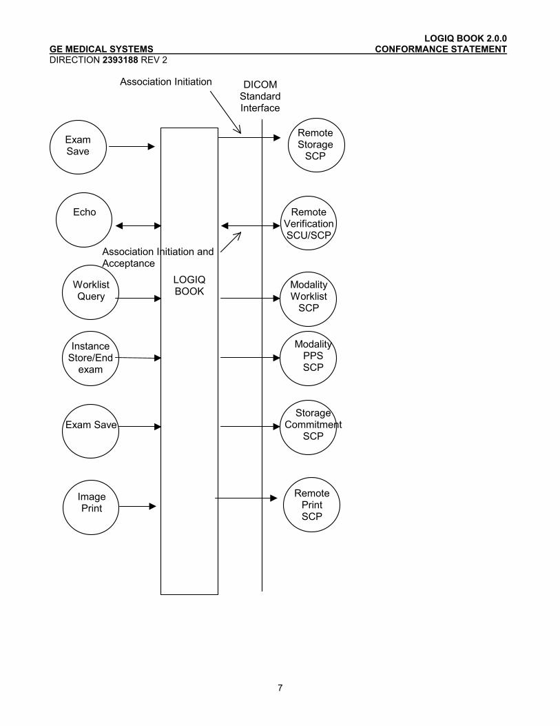
2.2.1 Application Data Flow Diagram
The Basic and Specific Application models for this device are shown in the following illustration:
LOGIQ BOOK 2.0.0 GE MEDICAL SYSTEMS CONFORMANCE STATEMENT DIRECTION 2393188 REV 2
7
Association Initiation
Association Initiation and Acceptance
Exam Save
LOGIQ BOOK
Remote Storage
SCP
Remote VerificationSCU/SCP
DICOM Standard Interface
Echo
Modality Worklist
SCP
Worklist Query
Storage Commitment
SCP Exam Save
Modality PPS SCP
Instance Store/End
exam
Image Print
Remote Print SCP
LOGIQ BOOK 2.0.0 GE MEDICAL SYSTEMS CONFORMANCE STATEMENT DIRECTION 2393188 REV 2
8
There are six local real-world activities that occur in LOGIQ BOOK - Exam Save, Echo, Worklist Query, Image Store/End Exam, Image Print
Exam save initiates a connection with the DICOM SCP and transmits images to the DICOM SCP. If Storage Commitment is configured a commitment request will be sent for the images.
Echo initiates a connection with the DICOM SCP, posts a Verification request and closes the connection. It also responds to incoming Verification requests (for service use).
Worklist Query initiates a connection with the DICOM SCP, performs a query and retrieves the matching entries to the product.
Image Store/End exam: If Modality Performed Procedure Step is configured N-CREATE and N-SET messages will be sent for the exam.
Image Print will send images to a DICOM Print SCP.
.
2.2.2 Functional Definition of AE's
Application Entity LOGIQ BOOK supports the following functions:
• Initiates a DICOM association to send images.
• Transmits DICOM images to the DICOM Storage SCP.
• Initiates a DICOM verification to assist in network diagnostics.
• Responds to DICOM verification requests from other devices.
• Initiates a DICOM worklist query to receive worklist information.
• Initiates a DICOM association to notify start of examination.
• Initiates a DICOM association to notify end of examination.
• Initiates a DICOM association to request storage commitment of images.
• Responds to replies for storage commitment requests of images.
• Initiates a DICOM association to print images.
2.2.3 Sequencing of Real-World Activities
Not applicable.
LOGIQ BOOK 2.0.0 GE MEDICAL SYSTEMS CONFORMANCE STATEMENT DIRECTION 2393188 REV 2
9
2.3 AE SPECIFICATIONS
2.3.1 LOGIQ BOOK AE Specification
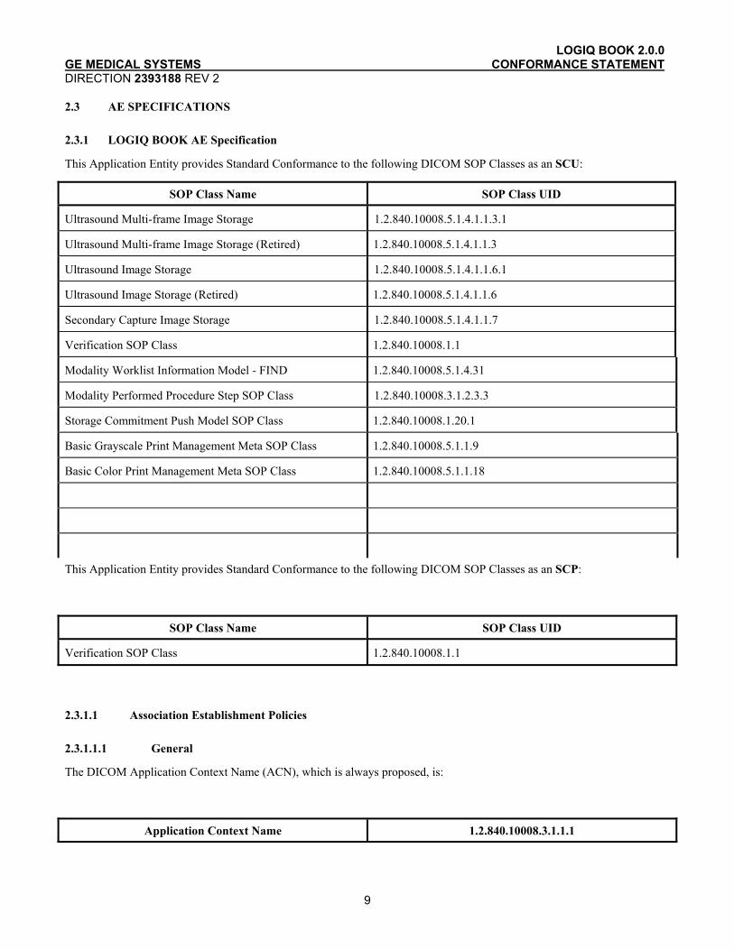
This Application Entity provides Standard Conformance to the following DICOM SOP Classes as an SCU:
SOP Class Name SOP Class UID
Ultrasound Multi-frame Image Storage 1.2.840.10008.5.1.4.1.1.3.1
Ultrasound Multi-frame Image Storage (Retired) 1.2.840.10008.5.1.4.1.1.3
Ultrasound Image Storage 1.2.840.10008.5.1.4.1.1.6.1
Ultrasound Image Storage (Retired) 1.2.840.10008.5.1.4.1.1.6
Secondary Capture Image Storage 1.2.840.10008.5.1.4.1.1.7
Verification SOP Class 1.2.840.10008.1.1
Modality Worklist Information Model - FIND 1.2.840.10008.5.1.4.31
Modality Performed Procedure Step SOP Class 1.2.840.10008.3.1.2.3.3
Storage Commitment Push Model SOP Class 1.2.840.10008.1.20.1
Basic Grayscale Print Management Meta SOP Class 1.2.840.10008.5.1.1.9
Basic Color Print Management Meta SOP Class 1.2.840.10008.5.1.1.18
This Application Entity provides Standard Conformance to the following DICOM SOP Classes as an SCP:
SOP Class Name SOP Class UID
Verification SOP Class 1.2.840.10008.1.1
2.3.1.1 Association Establishment Policies
2.3.1.1.1 General
The DICOM Application Context Name (ACN), which is always proposed, is:
Application Context Name 1.2.840.10008.3.1.1.1
LOGIQ BOOK 2.0.0 GE MEDICAL SYSTEMS CONFORMANCE STATEMENT DIRECTION 2393188 REV 2
10
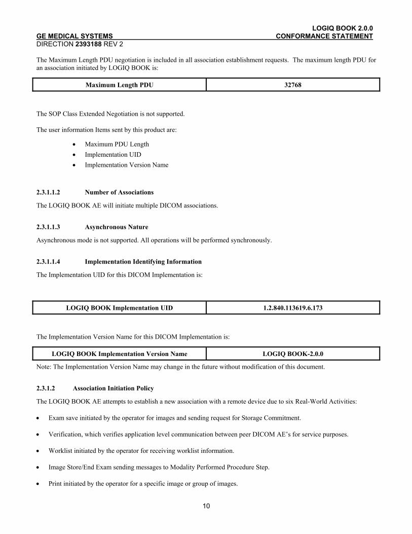
The Maximum Length PDU negotiation is included in all association establishment requests. The maximum length PDU for an association initiated by LOGIQ BOOK is:
Maximum Length PDU 32768
The SOP Class Extended Negotiation is not supported.
The user information Items sent by this product are:
• Maximum PDU Length • Implementation UID • Implementation Version Name
2.3.1.1.2 Number of Associations
The LOGIQ BOOK AE will initiate multiple DICOM associations.
2.3.1.1.3 Asynchronous Nature
Asynchronous mode is not supported. All operations will be performed synchronously.
2.3.1.1.4 Implementation Identifying Information
The Implementation UID for this DICOM Implementation is:
LOGIQ BOOK Implementation UID 1.2.840.113619.6.173
The Implementation Version Name for this DICOM Implementation is:
LOGIQ BOOK Implementation Version Name LOGIQ BOOK-2.0.0
Note: The Implementation Version Name may change in the future without modification of this document.
2.3.1.2 Association Initiation Policy
The LOGIQ BOOK AE attempts to establish a new association with a remote device due to six Real-World Activities:
• Exam save initiated by the operator for images and sending request for Storage Commitment.
• Verification, which verifies application level communication between peer DICOM AE’s for service purposes.
• Worklist initiated by the operator for receiving worklist information.
• Image Store/End Exam sending messages to Modality Performed Procedure Step.
• Print initiated by the operator for a specific image or group of images.
LOGIQ BOOK 2.0.0 GE MEDICAL SYSTEMS CONFORMANCE STATEMENT DIRECTION 2393188 REV 2
11
•
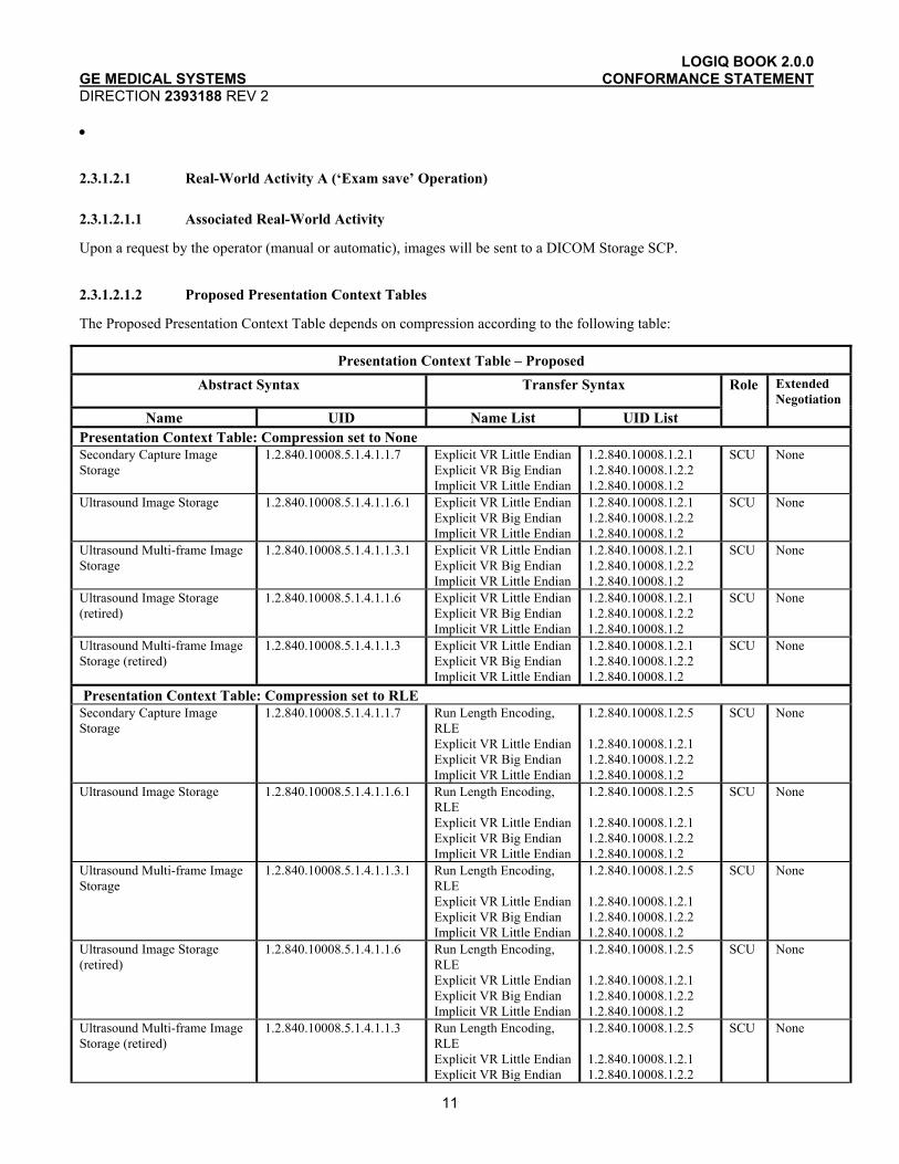
2.3.1.2.1 Real-World Activity A (‘Exam save’ Operation)
2.3.1.2.1.1 Associated Real-World Activity
Upon a request by the operator (manual or automatic), images will be sent to a DICOM Storage SCP.
2.3.1.2.1.2 Proposed Presentation Context Tables
The Proposed Presentation Context Table depends on compression according to the following table:
Presentation Context Table – Proposed Abstract Syntax Transfer Syntax Role Extended
Negotiation Name UID Name List UID List
Presentation Context Table: Compression set to None Secondary Capture Image Storage
1.2.840.10008.5.1.4.1.1.7 Explicit VR Little Endian Explicit VR Big Endian Implicit VR Little Endian
1.2.840.10008.1.2.1 1.2.840.10008.1.2.2 1.2.840.10008.1.2
SCU None
Ultrasound Image Storage 1.2.840.10008.5.1.4.1.1.6.1 Explicit VR Little Endian Explicit VR Big Endian Implicit VR Little Endian
1.2.840.10008.1.2.1 1.2.840.10008.1.2.2 1.2.840.10008.1.2
SCU None
Ultrasound Multi-frame Image Storage
1.2.840.10008.5.1.4.1.1.3.1 Explicit VR Little Endian Explicit VR Big Endian Implicit VR Little Endian
1.2.840.10008.1.2.1 1.2.840.10008.1.2.2 1.2.840.10008.1.2
SCU None
Ultrasound Image Storage (retired)
1.2.840.10008.5.1.4.1.1.6 Explicit VR Little Endian Explicit VR Big Endian Implicit VR Little Endian
1.2.840.10008.1.2.1 1.2.840.10008.1.2.2 1.2.840.10008.1.2
SCU None
Ultrasound Multi-frame Image Storage (retired)
1.2.840.10008.5.1.4.1.1.3 Explicit VR Little Endian Explicit VR Big Endian Implicit VR Little Endian
1.2.840.10008.1.2.1 1.2.840.10008.1.2.2 1.2.840.10008.1.2
SCU None
Presentation Context Table: Compression set to RLE Secondary Capture Image Storage
1.2.840.10008.5.1.4.1.1.7 Run Length Encoding, RLE Explicit VR Little Endian Explicit VR Big Endian Implicit VR Little Endian
1.2.840.10008.1.2.5 1.2.840.10008.1.2.1 1.2.840.10008.1.2.2 1.2.840.10008.1.2
SCU None
Ultrasound Image Storage 1.2.840.10008.5.1.4.1.1.6.1 Run Length Encoding, RLE Explicit VR Little Endian Explicit VR Big Endian Implicit VR Little Endian
1.2.840.10008.1.2.5 1.2.840.10008.1.2.1 1.2.840.10008.1.2.2 1.2.840.10008.1.2
SCU None
Ultrasound Multi-frame Image Storage
1.2.840.10008.5.1.4.1.1.3.1 Run Length Encoding, RLE Explicit VR Little Endian Explicit VR Big Endian Implicit VR Little Endian
1.2.840.10008.1.2.5 1.2.840.10008.1.2.1 1.2.840.10008.1.2.2 1.2.840.10008.1.2
SCU None
Ultrasound Image Storage (retired)
1.2.840.10008.5.1.4.1.1.6 Run Length Encoding, RLE Explicit VR Little Endian Explicit VR Big Endian Implicit VR Little Endian
1.2.840.10008.1.2.5 1.2.840.10008.1.2.1 1.2.840.10008.1.2.2 1.2.840.10008.1.2
SCU None
Ultrasound Multi-frame Image Storage (retired)
1.2.840.10008.5.1.4.1.1.3 Run Length Encoding, RLE Explicit VR Little Endian Explicit VR Big Endian
1.2.840.10008.1.2.5 1.2.840.10008.1.2.1 1.2.840.10008.1.2.2
SCU None

LOGIQ BOOK 2.0.0 GE MEDICAL SYSTEMS CONFORMANCE STATEMENT DIRECTION 2393188 REV 2
12
Implicit VR Little Endian 1.2.840.10008.1.2 Presentation Context Table: Compression set to JPEG Secondary Capture Image Storage
1.2.840.10008.5.1.4.1.1.7 JPEG Baseline
1.2.840.10008.1.2.4.50 SCU None
Ultrasound Image Storage 1.2.840.10008.5.1.4.1.1.6.1 JPEG Baseline
1.2.840.10008.1.2.4.50 SCU None
Ultrasound Multi-frame Image Storage
1.2.840.10008.5.1.4.1.1.3.1 JPEG Baseline
1.2.840.10008.1.2.4.50 SCU None
Ultrasound Image Storage 1.2.840.10008.5.1.4.1.1.6 JPEG Baseline
1.2.840.10008.1.2.4.50 SCU None
Ultrasound Multi-frame Image Storage (retired)
1.2.840.10008.5.1.4.1.1.3 JPEG Baseline
1.2.840.10008.1.2.4.50 SCU None
2.3.1.2.1.2.1 SOP Specific DICOM Conformance Statement for all Storage SOP Classes
This operation also sends a Storage Commitment Request, with the following proposed presentation context. The result from the SCP is expected on another association for the Storage Commitment result.
Presentation Context Table Proposed Abstract Syntax Transfer Syntax Role Extended
Name UID Name List UID List Negotiation
Storage Commitment Push Model SOP Class
1.2.840.10008.1.20.1 Explicit VR Little Endian Explicit VR Big Endian Implicit VR Little Endian
1.2.840.10008.1.2.1 1.2.840.10008.1.2.2 1.2.840.10008.1.2
SCU None
For this SOP class, all status codes with status Refused or Error are treated as failures and terminate the association and operation. All status codes with status Warning or Success are treated as successes.
2.3.1.2.2 Real-World Activity B (‘Echo’ Operation)
2.3.1.2.2.1 Associated Real-World Activity
The user may initiate a DICOM Verification Request in the Config screen.
Associations will be released upon the receipt of each C-ECHO confirmation.
In the event that the SCP does not respond, the operation will time out, close the association and inform the user.
2.3.1.2.2.2 Proposed Presentation Context Table
Presentation Context Table - Proposed
Abstract Syntax Transfer Syntax Role
Name UID Name List UID List
Extended
Negotiation
Verification SOP Class 1.2.840.10008.1.1 Explicit VR Little Endian Explicit VR Big Endian Implicit VR Little Endian
1.2.840.10008.1.2.1 1.2.840.10008.1.2.2 1.2.840.10008.1.2
SCU None
LOGIQ BOOK 2.0.0 GE MEDICAL SYSTEMS CONFORMANCE STATEMENT DIRECTION 2393188 REV 2
13
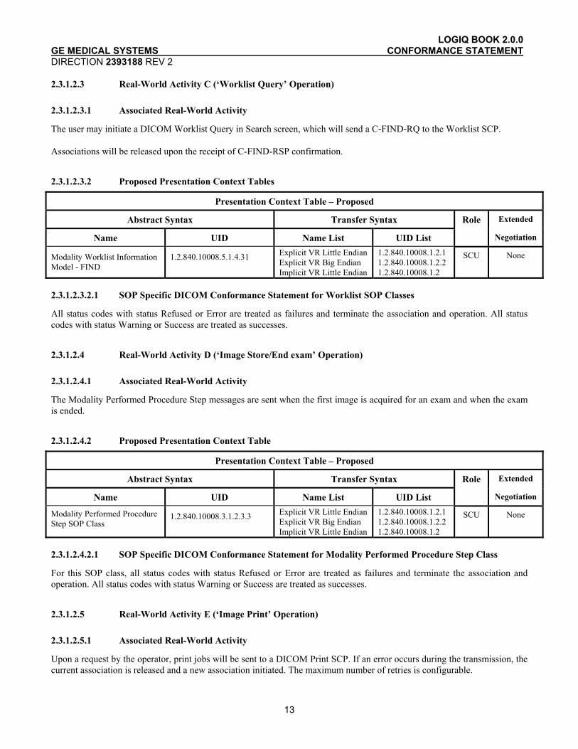
2.3.1.2.3 Real-World Activity C (‘Worklist Query’ Operation)
2.3.1.2.3.1 Associated Real-World Activity
The user may initiate a DICOM Worklist Query in Search screen, which will send a C-FIND-RQ to the Worklist SCP.
Associations will be released upon the receipt of C-FIND-RSP confirmation.
2.3.1.2.3.2 Proposed Presentation Context Tables
Presentation Context Table – Proposed
Abstract Syntax Transfer Syntax Role Extended
Name UID Name List UID List Negotiation
Modality Worklist Information Model - FIND
1.2.840.10008.5.1.4.31 Explicit VR Little Endian Explicit VR Big Endian Implicit VR Little Endian
1.2.840.10008.1.2.1 1.2.840.10008.1.2.2 1.2.840.10008.1.2
SCU None
2.3.1.2.3.2.1 SOP Specific DICOM Conformance Statement for Worklist SOP Classes
All status codes with status Refused or Error are treated as failures and terminate the association and operation. All status codes with status Warning or Success are treated as successes.
2.3.1.2.4 Real-World Activity D (‘Image Store/End exam’ Operation)
2.3.1.2.4.1 Associated Real-World Activity
The Modality Performed Procedure Step messages are sent when the first image is acquired for an exam and when the exam is ended.
2.3.1.2.4.2 Proposed Presentation Context Table
Presentation Context Table – Proposed
Abstract Syntax Transfer Syntax Role Extended
Name UID Name List UID List Negotiation
Modality Performed Procedure Step SOP Class
1.2.840.10008.3.1.2.3.3 Explicit VR Little Endian Explicit VR Big Endian Implicit VR Little Endian
1.2.840.10008.1.2.1 1.2.840.10008.1.2.2 1.2.840.10008.1.2
SCU None
2.3.1.2.4.2.1 SOP Specific DICOM Conformance Statement for Modality Performed Procedure Step Class
For this SOP class, all status codes with status Refused or Error are treated as failures and terminate the association and operation. All status codes with status Warning or Success are treated as successes.
2.3.1.2.5 Real-World Activity E (‘Image Print’ Operation)
2.3.1.2.5.1 Associated Real-World Activity
Upon a request by the operator, print jobs will be sent to a DICOM Print SCP. If an error occurs during the transmission, the current association is released and a new association initiated. The maximum number of retries is configurable.

LOGIQ BOOK 2.0.0 GE MEDICAL SYSTEMS CONFORMANCE STATEMENT DIRECTION 2393188 REV 2
14
2.3.1.2.5.2 Proposed Presentation Context Tables
The following table is used:
Presentation Context Table - Proposed
Abstract Syntax Transfer Syntax Role Extended
Name UID Name List UID List Negotiation
Basic Grayscale Print Management Meta SOP Class
1.2.840.10008.5.1.1.9 Explicit VR Little Endian Explicit VR Big Endian Implicit VR Little Endian
1.2.840.10008.1.2.1 1.2.840.10008.1.2.2 1.2.840.10008.1.2
SCU None
Basic Color Print Management Meta SOP Class
1.2.840.10008.5.1.1.18 Explicit VR Little Endian Explicit VR Big Endian Implicit VR Little Endian
1.2.840.10008.1.2.1 1.2.840.10008.1.2.2 1.2.840.10008.1.2
SCU None
2.3.1.2.5.2.1 SOP Specific DICOM Conformance Statement for all Print Management SOP Classes
All status codes with status Refused or Error are treated as failures and terminate the association and operation. All status codes with status Warning or Success are treated as successes.
2.3.1.3 Association Acceptance Policy
The AE accepts an association only when LOGIQ BOOK receives a Verification Request from another network device.
2.3.1.3.1 Real-World Activity B – (‘Echo’ operation)
2.3.1.3.1.1 Associated Real-World Activity
An incoming Verification Request will cause the AE to accept the association and respond with a Verification Response.
2.3.1.3.1.2 Accepted Presentation Context Table
Presentation Context Table - Accepted
Abstract Syntax Transfer Syntax Role Extended
Name UID Name List UID List Negotiation
Verification SOP Class 1.2.840.10008.1.1 Explicit VR Little Endian Explicit VR Big Endian Implicit VR Little Endian
1.2.840.10008.1.2.1 1.2.840.10008.1.2.2 1.2.840.10008.1.2
SCP None
2.3.1.3.1.2.1 SOP Specific DICOM Conformance Statement for Verify SOP Class
The AE provides standard conformance to the Verification SOP Class as an SCP. The port number used is configured in Config screen, default is 104.
2.3.1.3.1.3 Presentation Context Acceptance Criterion
No criterion.

LOGIQ BOOK 2.0.0 GE MEDICAL SYSTEMS CONFORMANCE STATEMENT DIRECTION 2393188 REV 2
15
2.3.1.3.1.4 Transfer Syntax Selection Policies
The selected transfer syntax is based on the proposed transfer syntax list. The priority order is Explicit VR Big Endian, Explicit VR Little Endian and Implicit VR Little Endian.
2.4 COMMUNICATION PROFILES
2.4.1 Supported Communication Stacks (PS 3.8, PS 3.9)
DICOM Upper Layer (PS 3.8) is supported using TCP/IP.
2.4.2 TCP/IP Stack
The TCP/IP stack is inherited from the product’s operating system. Please refer to product documentation for more information.
2.4.2.1 API
Not applicable to this product.
2.5 EXTENSIONS / SPECIALIZATIONS / PRIVATIZATIONS
If so configured, the product will send ultrasound raw data information in private data elements designated by the Private Creator element:
Element Name Tag VR VM Description
Private Creator 7FE1,00xx LO 1 GEMS_Ultrasound_MovieGroup_001
This means that all private tags starting with 7FE1,xx will belong to the GEMS_Ultrasound_MovieGroup_001.
If so configured, the product will send preview image in private data elements designated by the Private Creator element:
Element Name Tag VR VM Description
Private Creator 6003,00xx LO 1 GEMS_Ultrasound_ImageGroup_001
This means that all private tags starting with 6003,00xx will belong to the GEMS_Ultrasound_ImageGroup_001.
2.6 CONFIGURATION
2.6.1 AE Title/Presentation Address Mapping
The Local AE title is configurable through the Config screen, see below.
2.6.2 Configurable Parameters
Network:

LOGIQ BOOK 2.0.0 GE MEDICAL SYSTEMS CONFORMANCE STATEMENT DIRECTION 2393188 REV 2
16
• Local IP address • Local IP netmask • Local routing table information
Local:
• Local AE Title • Local port number
Verification:
• The AE Title, IP address and port number of the SCP • Max retries, Retry interval, Timeout
Modality Worklist:
• The AE Title, IP address and port number of the SCP • Max retries, Retry interval, Timeout • Refresh interval - the interval between downloads from the worklist. Searching for a patient within the time of a
refresh interval does not perform a new worklist query. • Disabling/enabling and setting constant values for query fields • Maximum number of downloaded entries
Storage:
• The AE Title, IP address and port number of the SCP • Max retries, Retry interval, Timeout • Enable/disable raw data • Frame rate reduction • Enable/disable multi-frame • Compression selection • Color support • Association strategies: one association per image or one association per exam •
Modality Performed Procedure Step:
• The AE Title, IP address and port number of the SCP • Max retries, Retry interval, Timeout
Storage Commitment:
• The AE Title, IP address and port number of the SCP • Max retries, Retry interval, Timeout • The associated Storage service which triggers the sending of Storage Commitment requests
Print:
• The AE Title, IP address and port number of the SCP • Max retries, Retry interval, Timeout • Configuration for each job according to attribute description in Section 11 of this document.
2.7 SUPPORT OF EXTENDED CHARACTER SETS
LOGIQ BOOK will support the ISO_IR 100 (ISO 8859-1:1987 Latin alphabet N 1. supplementary set) as extended character set. Any incoming SOP instance that is encoded using another extended character set will not be displayed.
LOGIQ BOOK 2.0.0 GE MEDICAL SYSTEMS CONFORMANCE STATEMENT DIRECTION 2393188 REV 2
17
2.8 CODES AND CONTROLLED TERMINOLOGY
2.8.1 Fixed Coded Terminology
The product uses the fixed (non-configurable, non-extensible) coded terminology in SR Document attributes, as described in Section Error! Reference source not found. Error! Reference source not found..
2.9 SECURITY PROFILES
The product does not conform to any defined DICOM Security Profiles.
It is assumed that the product is used within a secured environment. It is assumed that a secured environment includes at a minimum:
1. Firewall or router protections to ensure that only approved external hosts have network access to the product.
2. Firewall or router protections to ensure that the product only has network access to approved external hosts and services.
3. Any communications with external hosts and services outside the locally secured environment use appropriate secure network channels (such as a Virtual Private Network(VPN))
LOGIQ BOOK 2.0.0 GE MEDICAL SYSTEMS CONFORMANCE STATEMENT DIRECTION 2393188 REV 2
18
3. MEDIA STORAGE CONFORMANCE STATEMENT
3.1 INTRODUCTION
This section of the conformance statement (CS) specifies the LOGIQ BOOK compliance to DICOM Media Interchange. It details the DICOM Media Storage Application Profiles and roles, which are supported by this product.
LOGIQ BOOK is able to export images to DICOM media, browse DICOM media or read images from DICOM media.
3.2 IMPLEMENTATION MODEL
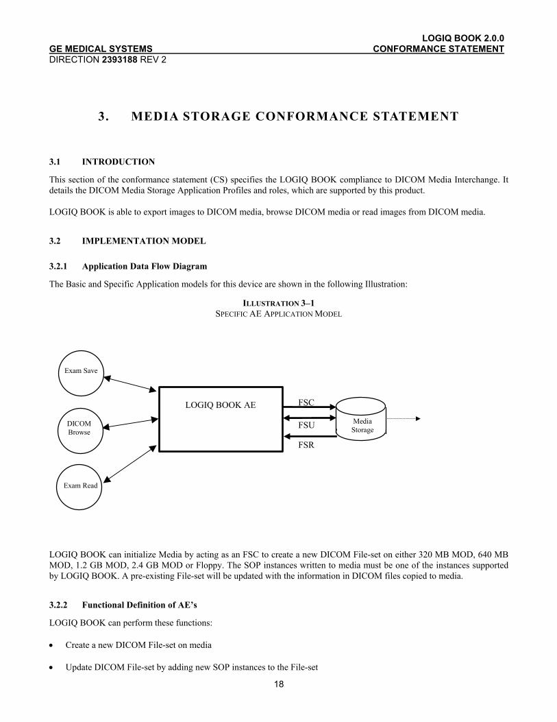
3.2.1 Application Data Flow Diagram
The Basic and Specific Application models for this device are shown in the following Illustration:
ILLUSTRATION 3–1 SPECIFIC AE APPLICATION MODEL
LOGIQ BOOK AE
Exam Save
FSC
FSR
DICOM Browse
Exam Read
FSU Media Storage
LOGIQ BOOK can initialize Media by acting as an FSC to create a new DICOM File-set on either 320 MB MOD, 640 MB MOD, 1.2 GB MOD, 2.4 GB MOD or Floppy. The SOP instances written to media must be one of the instances supported by LOGIQ BOOK. A pre-existing File-set will be updated with the information in DICOM files copied to media.
3.2.2 Functional Definition of AE’s
LOGIQ BOOK can perform these functions:
• Create a new DICOM File-set on media
• Update DICOM File-set by adding new SOP instances to the File-set
LOGIQ BOOK 2.0.0 GE MEDICAL SYSTEMS CONFORMANCE STATEMENT DIRECTION 2393188 REV 2
19
• Read information and images from the existing File-set
3.2.3 Sequencing Requirements
None applicable
3.2.4 File Meta Information Options (See PS3.10)
The File Meta-Information for this implementation is:
File Meta-Information Version 1
LOGIQ BOOK Implementation UID 1.2.840.113619.6.173
Implementation Version Name LOGIQ BOOK-2.0.0
Note: The Implementation Version Name and may change in the future without modification of this document.
3.3 AE SPECIFICATIONS
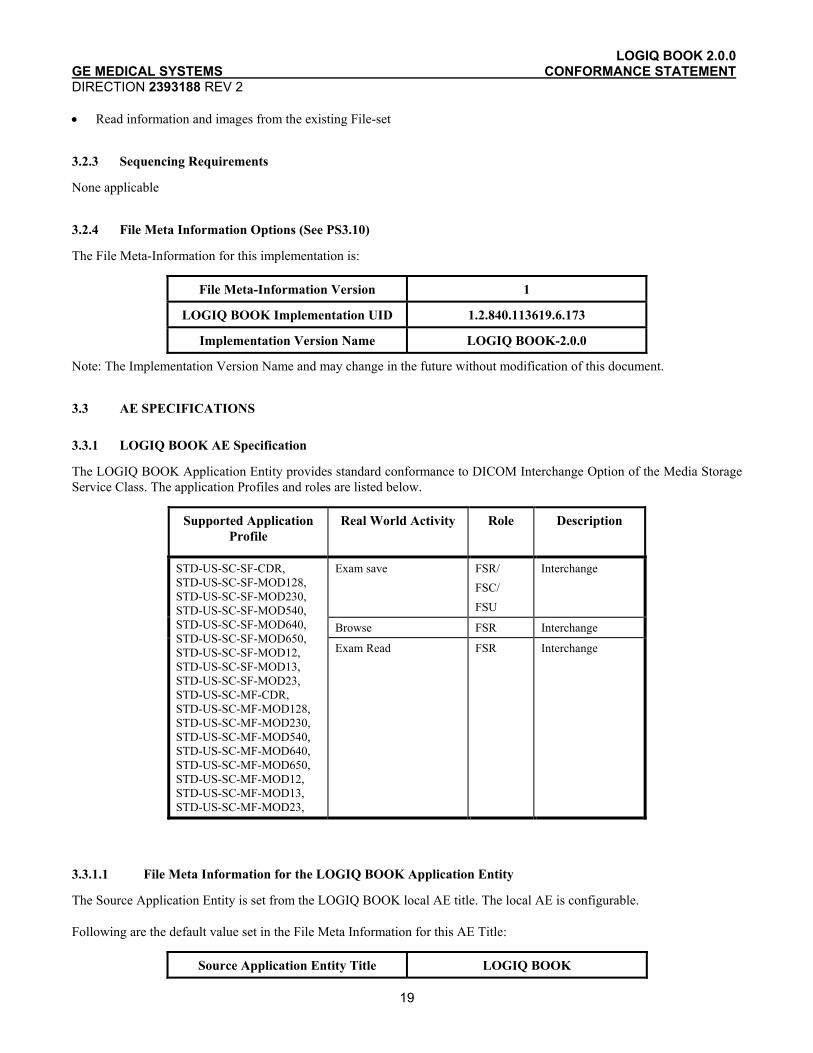
3.3.1 LOGIQ BOOK AE Specification
The LOGIQ BOOK Application Entity provides standard conformance to DICOM Interchange Option of the Media Storage Service Class. The application Profiles and roles are listed below.
Supported Application Profile
Real World Activity Role Description
Exam save FSR/ FSC/ FSU
Interchange
Browse FSR Interchange
STD-US-SC-SF-CDR, STD-US-SC-SF-MOD128, STD-US-SC-SF-MOD230, STD-US-SC-SF-MOD540, STD-US-SC-SF-MOD640, STD-US-SC-SF-MOD650, STD-US-SC-SF-MOD12, STD-US-SC-SF-MOD13, STD-US-SC-SF-MOD23, STD-US-SC-MF-CDR, STD-US-SC-MF-MOD128, STD-US-SC-MF-MOD230, STD-US-SC-MF-MOD540, STD-US-SC-MF-MOD640, STD-US-SC-MF-MOD650, STD-US-SC-MF-MOD12, STD-US-SC-MF-MOD13, STD-US-SC-MF-MOD23,
Exam Read FSR Interchange
3.3.1.1 File Meta Information for the LOGIQ BOOK Application Entity
The Source Application Entity is set from the LOGIQ BOOK local AE title. The local AE is configurable.
Following are the default value set in the File Meta Information for this AE Title:
Source Application Entity Title LOGIQ BOOK
LOGIQ BOOK 2.0.0 GE MEDICAL SYSTEMS CONFORMANCE STATEMENT DIRECTION 2393188 REV 2
20
3.3.1.2 Real-World Activities for the LOGIQ BOOK Application Entity
3.3.1.2.1 Real-World Activity “Exam save”
“Exam save” saves a DICOM SOP instance to media and updates DICOM File Set.
3.3.1.2.1.1 Media Storage Application Profile for the Real-World Activity “Exam save”:
For the list of Application Profiles that invoke this AE for “Exam save” Real-World Activity, see the Table in Section 3.3.1 “LOGIQ BOOK AE Specification” where the table describing the profiles and real-world activities is defined.
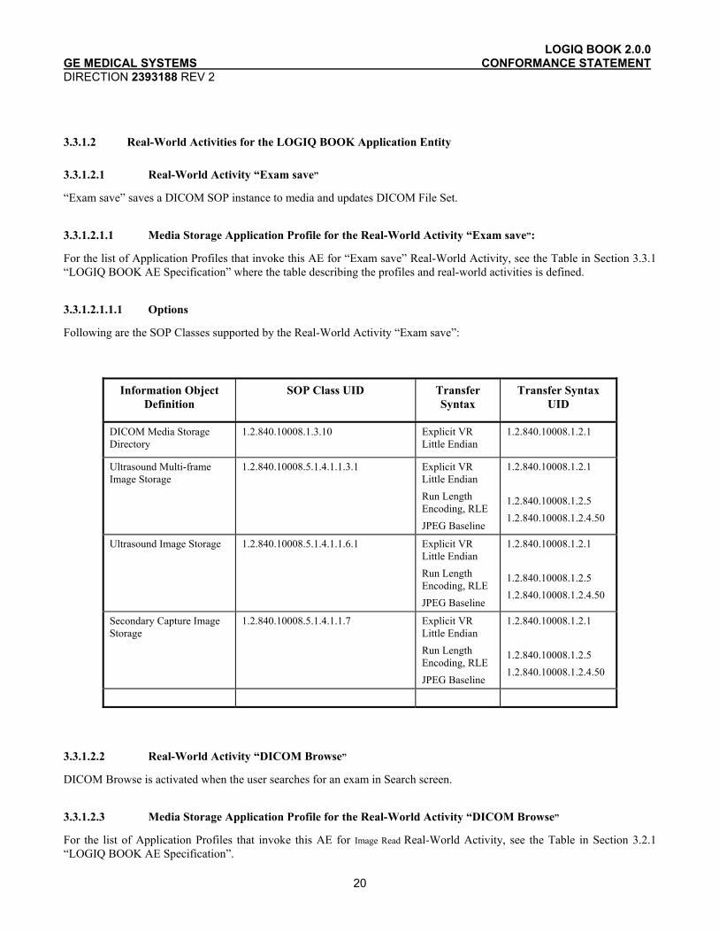
3.3.1.2.1.1.1 Options
Following are the SOP Classes supported by the Real-World Activity “Exam save”:
Information Object Definition
SOP Class UID Transfer Syntax
Transfer Syntax UID
DICOM Media Storage Directory
1.2.840.10008.1.3.10 Explicit VR Little Endian
1.2.840.10008.1.2.1
Ultrasound Multi-frame Image Storage
1.2.840.10008.5.1.4.1.1.3.1 Explicit VR Little Endian Run Length Encoding, RLE JPEG Baseline
1.2.840.10008.1.2.1 1.2.840.10008.1.2.5 1.2.840.10008.1.2.4.50
Ultrasound Image Storage 1.2.840.10008.5.1.4.1.1.6.1 Explicit VR Little Endian Run Length Encoding, RLE JPEG Baseline
1.2.840.10008.1.2.1 1.2.840.10008.1.2.5 1.2.840.10008.1.2.4.50
Secondary Capture Image Storage
1.2.840.10008.5.1.4.1.1.7 Explicit VR Little Endian Run Length Encoding, RLE JPEG Baseline
1.2.840.10008.1.2.1 1.2.840.10008.1.2.5 1.2.840.10008.1.2.4.50
3.3.1.2.2 Real-World Activity “DICOM Browse”
DICOM Browse is activated when the user searches for an exam in Search screen.
3.3.1.2.3 Media Storage Application Profile for the Real-World Activity “DICOM Browse”
For the list of Application Profiles that invoke this AE for Image Read Real-World Activity, see the Table in Section 3.2.1 “LOGIQ BOOK AE Specification”.

LOGIQ BOOK 2.0.0 GE MEDICAL SYSTEMS CONFORMANCE STATEMENT DIRECTION 2393188 REV 2
21
3.3.1.2.3.1.1 Options
Following are the SOP Classes supported by the Real-World Activity DICOM Browse:
Information Object Definition
SOP Class UID Transfer Syntax Transfer Syntax UID
DICOM Media Storage Directory
1.2.840.10008.1.3.10 Explicit VR Little Endian
1.2.840.10008.1.2.1
Explicit VR Little Endian
1.2.840.10008.1.2.1
Explicit VR Big Endian 1.2.840.10008.1.2.2
Implicit VR Little Endian
1.2.840.10008.1.2
Run Length Encoding, RLE
1.2.840.10008.1.2.5
Ultrasound Multi-frame Image Storage
1.2.840.10008.5.1.4.1.1.3.1
JPEG Baseline 1.2.840.10008.1.2.4.50
Explicit VR Little Endian
1.2.840.10008.1.2.1
Explicit VR Big Endian 1.2.840.10008.1.2.2
Implicit VR Little Endian
1.2.840.10008.1.2
Run Length Encoding, RLE
1.2.840.10008.1.2.5
Ultrasound Multi-frame Image Storage(retired)
1.2.840.10008.5.1.4.1.1.3
JPEG Baseline 1.2.840.10008.1.2.4.50
Explicit VR Little Endian
1.2.840.10008.1.2.1
Explicit VR Big Endian 1.2.840.10008.1.2.2
Implicit VR Little Endian
1.2.840.10008.1.2
Run Length Encoding, RLE
1.2.840.10008.1.2.5
Ultrasound Image Storage 1.2.840.10008.5.1.4.1.1.6.1
JPEG Baseline 1.2.840.10008.1.2.4.50
Explicit VR Little Endian
1.2.840.10008.1.2.1
Explicit VR Big Endian 1.2.840.10008.1.2.2
Implicit VR Little Endian
1.2.840.10008.1.2
Run Length Encoding, RLE
1.2.840.10008.1.2.5
Ultrasound Image Storage (retired)
1.2.840.10008.5.1.4.1.1.6
JPEG Baseline 1.2.840.10008.1.2.4.50

LOGIQ BOOK 2.0.0 GE MEDICAL SYSTEMS CONFORMANCE STATEMENT DIRECTION 2393188 REV 2
22
Explicit VR Little Endian
1.2.840.10008.1.2.1
Explicit VR Big Endian 1.2.840.10008.1.2.2
Implicit VR Little Endian
1.2.840.10008.1.2
Run Length Encoding, RLE
1.2.840.10008.1.2.5
Secondary Capture Image Storage
1.2.840.10008.5.1.4.1.1.7
JPEG Baseline 1.2.840.10008.1.2.4.50
3.3.1.2.4 Real-World Activity “Exam read“
“Exam read” reads and displays a DICOM SOP instance from media.
3.3.1.2.4.1 Media Storage Application Profile for the Real-World Activity “Exam read “
For the list of Application Profiles that invoke this AE for Exam read Real-World Activity, see the Table in Section 3.2.1 “LOGIQ BOOK AE Specification”.
3.3.1.2.4.1.1 Options
Following are the SOP Classes supported by the Exam read Real-World Activity:
Information Object Definition
SOP Class UID Transfer Syntax
Transfer Syntax UID
DICOM Media Storage Directory
1.2.840.10008.1.3.10 Explicit VR Little Endian
1.2.840.10008.1.2.1
Explicit VR Little Endian
1.2.840.10008.1.2.1
Explicit VR Big Endian
1.2.840.10008.1.2.2
Implicit VR Little Endian
1.2.840.10008.1.2
Run Length Encoding, RLE
1.2.840.10008.1.2.5
Ultrasound Multi-frame Image Storage
1.2.840.10008.5.1.4.1.1.3.1
JPEG Baseline 1.2.840.10008.1.2.4.50
Explicit VR Little Endian
1.2.840.10008.1.2.1
Explicit VR Big Endian
1.2.840.10008.1.2.2
Implicit VR Little Endian
1.2.840.10008.1.2
Run Length Encoding, RLE
1.2.840.10008.1.2.5
Ultrasound Multi-frame Image Storage(retired)
1.2.840.10008.5.1.4.1.1.3
JPEG Baseline 1.2.840.10008.1.2.4.50
Ultrasound Image Storage 1.2.840.10008.5.1.4.1.1.6.1 Explicit VR Little Endian
1.2.840.10008.1.2.1

LOGIQ BOOK 2.0.0 GE MEDICAL SYSTEMS CONFORMANCE STATEMENT DIRECTION 2393188 REV 2
23
Explicit VR Big Endian
1.2.840.10008.1.2.2
Implicit VR Little Endian
1.2.840.10008.1.2
Run Length Encoding, RLE
1.2.840.10008.1.2.5
JPEG Baseline 1.2.840.10008.1.2.4.50
Explicit VR Little Endian
1.2.840.10008.1.2.1
Explicit VR Big Endian
1.2.840.10008.1.2.2
Implicit VR Little Endian
1.2.840.10008.1.2
Run Length Encoding, RLE
1.2.840.10008.1.2.5
Ultrasound Image Storage (retired)
1.2.840.10008.5.1.4.1.1.6
JPEG Baseline 1.2.840.10008.1.2.4.50
Explicit VR Little Endian
1.2.840.10008.1.2.1
Explicit VR Big Endian
1.2.840.10008.1.2.2
Implicit VR Little Endian
1.2.840.10008.1.2
Run Length Encoding, RLE
1.2.840.10008.1.2.5
Secondary Capture Image Storage
1.2.840.10008.5.1.4.1.1.7
JPEG Baseline 1.2.840.10008.1.2.4.50
3.4 AUGMENTED AND PRIVATE APPLICATION PROFILES
LOGIQ BOOK creates Secondary Capture Image Objects in addition to the objects defined in the application profiles.
3.5 EXTENSIONS, SPECIALIZATIONS, PRIVATIZATIONS OF SOP CLASSES AND TRANSFER SYNTAXES
If so configured, the product will send ultrasound raw data information in private data elements designated by the Private Creator element:
Element Name Tag VR VM Description
Private Creator 7FE1,00xx LO 1 GEMS_Ultrasound_MovieGroup_001
This means that all private tags starting with 7FE1,00xx will belong to the GEMS_Ultrasound_MovieGroup_001.
If so configured, the product will send preview image in private data elements designated by the Private Creator element:
Element Name Tag VR VM Description
Private Creator 6003,00xx LO 1 GEMS_Ultrasound_ImageGroup_001
LOGIQ BOOK 2.0.0 GE MEDICAL SYSTEMS CONFORMANCE STATEMENT DIRECTION 2393188 REV 2
24
This means that all private tags starting with 6003,00xx will belong to the GEMS_Ultrasound_ImageGroup_001.
3.6 CONFIGURATION
The following parameters are configurable: • Location of DICOMDIR • Read or Read/Write • Enable/disable raw data • Frame rate reduction • Enable/disable multi-frame • Compression selection • Include image
3.7 SUPPORT OF EXTENDED CHARACTER SETS
LOGIQ BOOK will support only the ISO_IR 100 (ISO 8859-1:1987 Latin alphabet N 1. supplementary set) as extended character sets. Any incoming SOP instance that is encoded using another extended character set will not be read.

LOGIQ BOOK 2.0.0 GE MEDICAL SYSTEMS CONFORMANCE STATEMENT DIRECTION 2393188 REV 2
25
4. ULTRASOUND (US) INFORMATION OBJECT IMPLEMENTATION
4.1 INTRODUCTION
This section specifies the use of the DICOM US Image IOD to represent the information included in US images produced by this implementation. Corresponding attributes are conveyed using the module construct. The contents of this section are:
4.2 - IOD Implementation
4.3 - IOD Entity-Relationship Model
4.4 - IOD Module Table
4.5 - IOD Module Definition
In this section, supported means that tag is sent with value.
4.2 US IOD IMPLEMENTATION
This section defines the implementation of US image information object.
4.3 US ENTITY-RELATIONSHIP MODEL
The Entity-Relationship diagram for the US Image interoperability schema is shown in Illustration 4.3-1. In this figure, the following diagrammatic convention is established to represent the information organization:
• each entity is represented by a rectangular box • each relationship is represented by a diamond shaped box. • the fact that a relationship exists between two entities is depicted by lines connecting the corresponding
entity boxes to the relationship boxes.
The relationships are fully defined with the maximum number of possible entities in the relationship shown. In other words, the relationship between Series and Image can have up to n Images per Series, but the Patient to Study relationship has 1 Study for each Patient (a Patient can have more than one Study on the system, however each Study will contain all of the information pertaining to that Patient).

LOGIQ BOOK 2.0.0 GE MEDICAL SYSTEMS CONFORMANCE STATEMENT DIRECTION 2393188 REV 2
26
ILLUSTRATION 4.3-1 US IMAGE ENTITY RELATIONSHIP DIAGRAM
Patient
Study
is the subject
of
contains
creates
Equipment
US Image
contains
Series
0,n
1 1 1,n
1,n
1
1,n
1
4.3.1 Entity Descriptions
Please refer to DICOM Standard Part 3 (Information Object Definitions) for a description of each of the entities contained within the US Information Object.
4.3.2 LOGIQ BOOK Mapping of DICOM Entities
TABLE 4.3-1 MAPPING OF DICOM ENTITIES TO LOGIQ BOOK ENTITIES
DICOM LOGIQ BOOK Entity
Patient Patient
Study Exam
Series Exam
Image Image
Curve Not used

LOGIQ BOOK 2.0.0 GE MEDICAL SYSTEMS CONFORMANCE STATEMENT DIRECTION 2393188 REV 2
27
4.4 IOD MODULE TABLE
Within an entity of the DICOM US IOD, attributes are grouped into related set of attributes. A set of related attributes is termed a module. A module facilitates the understanding of the semantics concerning the attributes and how the attributes are related with each other. A module grouping does not infer any encoding of information into data sets.
Table 4.4-1 identifies the defined modules within the entities, which comprise the DICOM US IOD. Modules are identified by Module Name.
See DICOM Part 3 for a complete definition of the entities, modules, and attributes.
Only the single frame US Image IOD is described here.
TABLE 4.4-1 US IMAGE IOD MODULES
Entity Name Module Name Reference
Patient Patient 4.5.1.1
General Study 4.5.2.1 Study
Patient Study 4.5.2.2
Series General Series 4.5.3.1
Frame of Reference Not used Frame of Reference
US Frame of Reference Not used
Equipment General Equipment 4.5.4.1
General Image 4.5.5.1
Image Pixel 4.5.5.2
Contrast/Bolus 4.5.5.3
Palette Color Lookup Table 4.5.5.4
US Region Calibration 4.5.7.1
US Image 4.5.7.2
Overlay Plane Not used
VOI LUT 4.5.5.5
Image
SOP Common 4.5.6.1
Curve Not used
4.5 INFORMATION MODULE DEFINITIONS
Please refer to DICOM Standard Part 3 (Information Object Definitions) for a description of each of the entities and modules contained within the US Information Object.
The following modules are included to convey Enumerated Values, Defined Terms, and Optional Attributes supported. Type 1 & Type 2 Attributes are also included for completeness and to define what values they may take and where these values are obtained. It should be noted that they are the same ones as defined in the DICOM Standard Part 3 (Information Object Definitions).
LOGIQ BOOK 2.0.0 GE MEDICAL SYSTEMS CONFORMANCE STATEMENT DIRECTION 2393188 REV 2
28
4.5.1 Common Patient Entity Modules
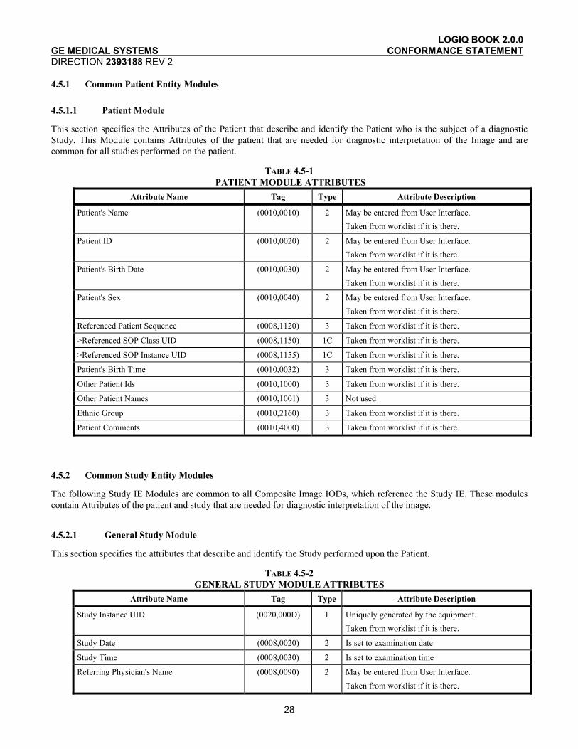
4.5.1.1 Patient Module
This section specifies the Attributes of the Patient that describe and identify the Patient who is the subject of a diagnostic Study. This Module contains Attributes of the patient that are needed for diagnostic interpretation of the Image and are common for all studies performed on the patient.
TABLE 4.5-1 PATIENT MODULE ATTRIBUTES
Attribute Name Tag Type Attribute Description
Patient's Name (0010,0010) 2 May be entered from User Interface. Taken from worklist if it is there.
Patient ID (0010,0020) 2 May be entered from User Interface. Taken from worklist if it is there.
Patient's Birth Date (0010,0030) 2 May be entered from User Interface. Taken from worklist if it is there.
Patient's Sex (0010,0040) 2 May be entered from User Interface. Taken from worklist if it is there.
Referenced Patient Sequence (0008,1120) 3 Taken from worklist if it is there.
>Referenced SOP Class UID (0008,1150) 1C Taken from worklist if it is there.
>Referenced SOP Instance UID (0008,1155) 1C Taken from worklist if it is there.
Patient's Birth Time (0010,0032) 3 Taken from worklist if it is there.
Other Patient Ids (0010,1000) 3 Taken from worklist if it is there.
Other Patient Names (0010,1001) 3 Not used
Ethnic Group (0010,2160) 3 Taken from worklist if it is there.
Patient Comments (0010,4000) 3 Taken from worklist if it is there.
4.5.2 Common Study Entity Modules
The following Study IE Modules are common to all Composite Image IODs, which reference the Study IE. These modules contain Attributes of the patient and study that are needed for diagnostic interpretation of the image.
4.5.2.1 General Study Module
This section specifies the attributes that describe and identify the Study performed upon the Patient.
TABLE 4.5-2 GENERAL STUDY MODULE ATTRIBUTES
Attribute Name Tag Type Attribute Description
Study Instance UID (0020,000D) 1 Uniquely generated by the equipment. Taken from worklist if it is there.
Study Date (0008,0020) 2 Is set to examination date
Study Time (0008,0030) 2 Is set to examination time
Referring Physician's Name (0008,0090) 2 May be entered from User Interface. Taken from worklist if it is there.

LOGIQ BOOK 2.0.0 GE MEDICAL SYSTEMS CONFORMANCE STATEMENT DIRECTION 2393188 REV 2
29
Study ID (0020,0010) 2 May be entered from User Interface. Taken from worklist if it is there (from Requested Procedure Id)
Accession Number (0008,0050) 2 May be entered from User Interface. Taken from worklist if it is there.
Study Description (0008,1030) 3 Taken from worklist if it is there (from Requested Procedure Description).
Physician(s) of Record (0008,1048) 3 Taken from worklist if it is there (from Names of Intended Recipients of Result)
Name of Physician(s) Reading Study (0008,1060) 3 Not used
Referenced Study Sequence (0008,1110) 3 Taken from worklist if it is there. (Not used in SR Documents.)
>Referenced SOP Class UID (0008,1150) 1C Taken from worklist if it is there. (Not used in SR Documents.)
>Referenced SOP Instance UID (0008,1155) 1C Taken from worklist if it is there. (Not used in SR Documents.)
4.5.2.2 Patient Study Module
This section defines attributes that provide information about the Patient at the time that the Study was performed.
TABLE 4.5-3 PATIENT STUDY MODULE ATTRIBUTES
Attribute Name Tag Type Attribute Description
Admitting Diagnoses Description (0008,1080) 3 Not used
Patient's Age (0010,1010) 3 Not used
Patient's Size (0010,1020) 3 May be entered from User Interface. Taken from worklist if it is there.
Patient's Weight (0010,1030) 3 May be entered from User Interface. Taken from worklist if it is there.
Occupation (0010,2180) 3 Not used
Additional Patient’s History (0010,21B0) 3 May be entered from User Interface (in Referral reason). Taken from worklist if it is there.
LOGIQ BOOK 2.0.0 GE MEDICAL SYSTEMS CONFORMANCE STATEMENT DIRECTION 2393188 REV 2
30
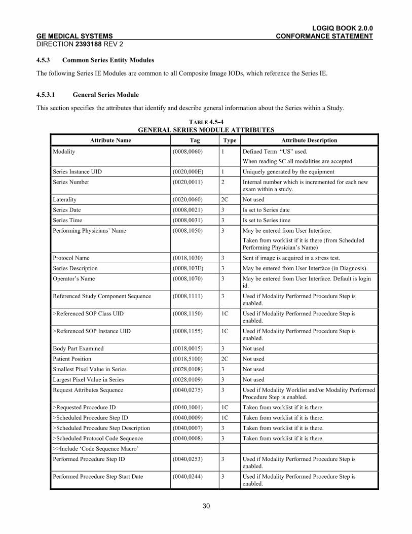
4.5.3 Common Series Entity Modules
The following Series IE Modules are common to all Composite Image IODs, which reference the Series IE.
4.5.3.1 General Series Module
This section specifies the attributes that identify and describe general information about the Series within a Study.
TABLE 4.5-4 GENERAL SERIES MODULE ATTRIBUTES
Attribute Name Tag Type Attribute Description
Modality (0008,0060) 1 Defined Term “US” used. When reading SC all modalities are accepted.
Series Instance UID (0020,000E) 1 Uniquely generated by the equipment
Series Number (0020,0011) 2 Internal number which is incremented for each new exam within a study.
Laterality (0020,0060) 2C Not used
Series Date (0008,0021) 3 Is set to Series date
Series Time (0008,0031) 3 Is set to Series time
Performing Physicians’ Name (0008,1050) 3 May be entered from User Interface. Taken from worklist if it is there (from Scheduled Performing Physician’s Name)
Protocol Name (0018,1030) 3 Sent if image is acquired in a stress test.
Series Description (0008,103E) 3 May be entered from User Interface (in Diagnosis).
Operator’s Name (0008,1070) 3 May be entered from User Interface. Default is login id.
Referenced Study Component Sequence (0008,1111) 3 Used if Modality Performed Procedure Step is enabled.
>Referenced SOP Class UID (0008,1150) 1C Used if Modality Performed Procedure Step is enabled.
>Referenced SOP Instance UID (0008,1155) 1C Used if Modality Performed Procedure Step is enabled.
Body Part Examined (0018,0015) 3 Not used
Patient Position (0018,5100) 2C Not used
Smallest Pixel Value in Series (0028,0108) 3 Not used
Largest Pixel Value in Series (0028,0109) 3 Not used
Request Attributes Sequence (0040,0275) 3 Used if Modality Worklist and/or Modality Performed Procedure Step is enabled.
>Requested Procedure ID (0040,1001) 1C Taken from worklist if it is there.
>Scheduled Procedure Step ID (0040,0009) 1C Taken from worklist if it is there.
>Scheduled Procedure Step Description (0040,0007) 3 Taken from worklist if it is there.
>Scheduled Protocol Code Sequence (0040,0008) 3 Taken from worklist if it is there.
>>Include ‘Code Sequence Macro’
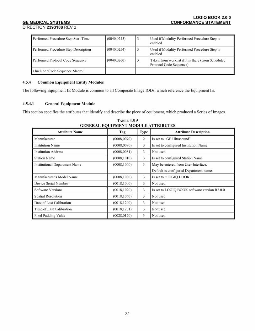
Performed Procedure Step ID (0040,0253) 3 Used if Modality Performed Procedure Step is enabled.
Performed Procedure Step Start Date (0040,0244) 3 Used if Modality Performed Procedure Step is enabled.
LOGIQ BOOK 2.0.0 GE MEDICAL SYSTEMS CONFORMANCE STATEMENT DIRECTION 2393188 REV 2
31
Performed Procedure Step Start Time (0040,0245) 3 Used if Modality Performed Procedure Step is enabled.
Performed Procedure Step Description (0040,0254) 3 Used if Modality Performed Procedure Step is enabled.
Performed Protocol Code Sequence (0040,0260) 3 Taken from worklist if it is there (from Scheduled Protocol Code Sequence)
>Include ‘Code Sequence Macro’
4.5.4 Common Equipment Entity Modules
The following Equipment IE Module is common to all Composite Image IODs, which reference the Equipment IE.
4.5.4.1 General Equipment Module
This section specifies the attributes that identify and describe the piece of equipment, which produced a Series of Images.
TABLE 4.5-5 GENERAL EQUIPMENT MODULE ATTRIBUTES
Attribute Name Tag Type Attribute Description
Manufacturer (0008,0070) 2 Is set to “GE Ultrasound”
Institution Name (0008,0080) 3 Is set to configured Institution Name.
Institution Address (0008,0081) 3 Not used
Station Name (0008,1010) 3 Is set to configured Station Name.
Institutional Department Name (0008,1040) 3 May be entered from User Interface. Default is configured Department name.
Manufacturer's Model Name (0008,1090) 3 Is set to “LOGIQ BOOK”.
Device Serial Number (0018,1000) 3 Not used
Software Versions (0018,1020) 3 Is set to LOGIQ BOOK software version R2.0.0
Spatial Resolution (0018,1050) 3 Not used
Date of Last Calibration (0018,1200) 3 Not used
Time of Last Calibration (0018,1201) 3 Not used
Pixel Padding Value (0028,0120) 3 Not used
LOGIQ BOOK 2.0.0 GE MEDICAL SYSTEMS CONFORMANCE STATEMENT DIRECTION 2393188 REV 2
32
4.5.5 Common Image Entity Modules
The following Image IE Modules are common to all Composite Image IODs, which reference the Image IE.
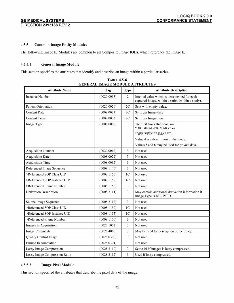
4.5.5.1 General Image Module
This section specifies the attributes that identify and describe an image within a particular series.
TABLE 4.5-6 GENERAL IMAGE MODULE ATTRIBUTES
Attribute Name Tag Type Attribute Description
Instance Number (0020,0013) 2 Internal value which is incremented for each captured image, within a series (within a study),
Patient Orientation (0020,0020) 2C Sent with empty value.
Content Date (0008,0023) 2C Set from Image date
Content Time (0008,0033) 2C Set from Image time
Image Type (0008,0008) 3 The first two values contain “ORIGINAL/PRIMARY” or “DERIVED/ PRIMARY”. Value 4 is a description of the mode. Values 5 and 6 may be used for private data.
Acquisition Number (0020,0012) 3 Not used
Acquisition Date (0008,0022) 3 Not used
Acquisition Time (0008,0032) 3 Not used
Referenced Image Sequence (0008,1140) 3 Not used
>Referenced SOP Class UID (0008,1150) 1C Not used
>Referenced SOP Instance UID (0008,1155) 1C Not used
>Referenced Frame Number (0008,1160) 3 Not used
Derivation Description (0008,2111) 3 May contain additional derivation information if Image Type is DERIVED.
Source Image Sequence (0008,2112) 3 Not used
>Referenced SOP Class UID (0008,1150) 1C Not used
>Referenced SOP Instance UID (0008,1155) 1C Not used
>Referenced Frame Number (0008,1160) 3 Not used
Images in Acquisition (0020,1002) 3 Not used
Image Comments (0020,4000) 3 May be used for description of the image
Quality Control Image (0028,0300) 3 Not used
Burned In Annotation (0028,0301) 3 Not used
Lossy Image Compression (0028,2110) 3 Set to 01 if images is lossy compressed.
Lossy Image Compression Ratio (0028,2112) 3 Used if lossy compressed.
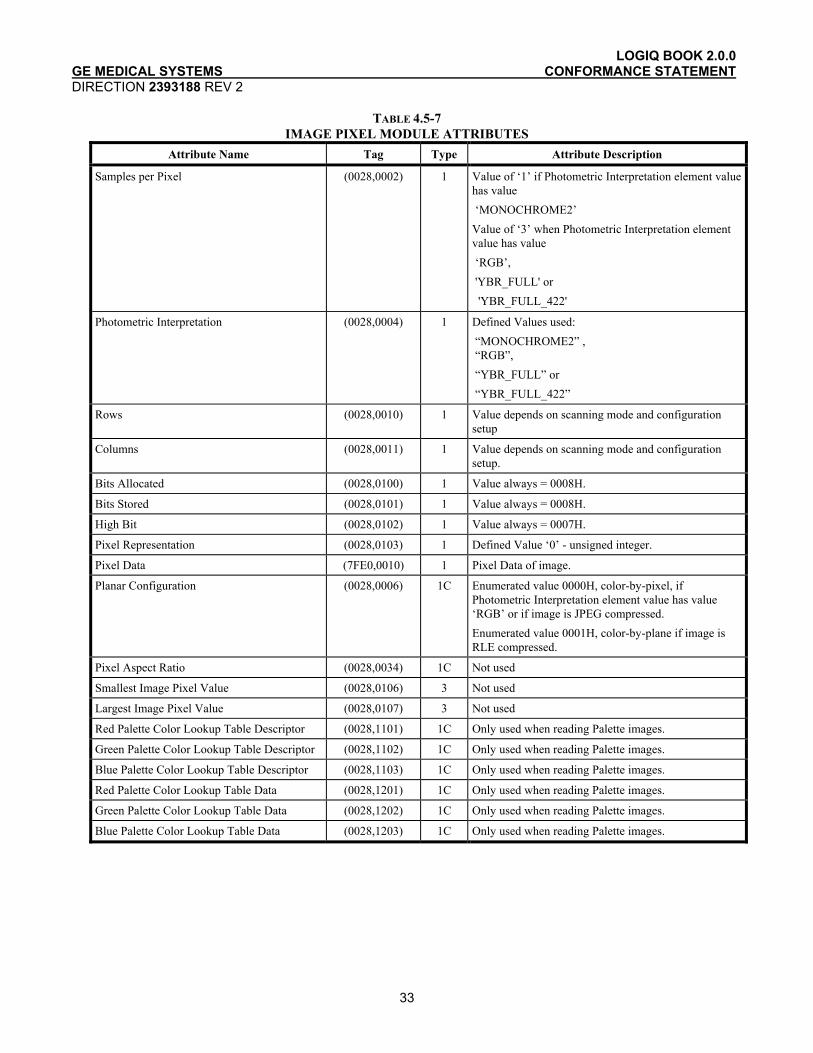
4.5.5.2 Image Pixel Module
This section specified the attributes that describe the pixel data of the image.
LOGIQ BOOK 2.0.0 GE MEDICAL SYSTEMS CONFORMANCE STATEMENT DIRECTION 2393188 REV 2
33
TABLE 4.5-7 IMAGE PIXEL MODULE ATTRIBUTES
Attribute Name Tag Type Attribute Description
Samples per Pixel (0028,0002) 1 Value of ‘1’ if Photometric Interpretation element value has value ‘MONOCHROME2’ Value of ‘3’ when Photometric Interpretation element value has value ‘RGB’, 'YBR_FULL' or 'YBR_FULL_422'
Photometric Interpretation (0028,0004) 1 Defined Values used: “MONOCHROME2” , “RGB”, “YBR_FULL” or “YBR_FULL_422”
Rows (0028,0010) 1 Value depends on scanning mode and configuration setup
Columns (0028,0011) 1 Value depends on scanning mode and configuration setup.
Bits Allocated (0028,0100) 1 Value always = 0008H.
Bits Stored (0028,0101) 1 Value always = 0008H.
High Bit (0028,0102) 1 Value always = 0007H.
Pixel Representation (0028,0103) 1 Defined Value ‘0’ - unsigned integer.
Pixel Data (7FE0,0010) 1 Pixel Data of image.
Planar Configuration (0028,0006) 1C Enumerated value 0000H, color-by-pixel, if Photometric Interpretation element value has value ‘RGB’ or if image is JPEG compressed. Enumerated value 0001H, color-by-plane if image is RLE compressed.
Pixel Aspect Ratio (0028,0034) 1C Not used
Smallest Image Pixel Value (0028,0106) 3 Not used
Largest Image Pixel Value (0028,0107) 3 Not used
Red Palette Color Lookup Table Descriptor (0028,1101) 1C Only used when reading Palette images.
Green Palette Color Lookup Table Descriptor (0028,1102) 1C Only used when reading Palette images.
Blue Palette Color Lookup Table Descriptor (0028,1103) 1C Only used when reading Palette images.
Red Palette Color Lookup Table Data (0028,1201) 1C Only used when reading Palette images.
Green Palette Color Lookup Table Data (0028,1202) 1C Only used when reading Palette images.
Blue Palette Color Lookup Table Data (0028,1203) 1C Only used when reading Palette images.

LOGIQ BOOK 2.0.0 GE MEDICAL SYSTEMS CONFORMANCE STATEMENT DIRECTION 2393188 REV 2
34
4.5.5.3 Contrast/Bolus Module
This section specifies the attributes that describe the contrast /bolus used in the acquisition of the Image.
TABLE 4.5-8 CONTRAST/BOLUS MODULE ATTRIBUTES
Attribute Name Tag Type Attribute Description
Contrast/Bolus Agent (0018,0010) 2 May be entered from User Interface.
Contrast/Bolus Agent Sequence (0018,0012) 3 Not used
>Include ‘Code Sequence Macro’
Contrast/Bolus Route (0018,1040) 3 Not used
Contrast/Bolus Administration Route Sequence
(0018,0014) 3 Not used
>Include ‘Code Sequence Macro’
>Additional Drug Sequence (0018,002A) 3 Not used
>>Include ‘Code Sequence Macro’
Contrast/Bolus Volume (0018,1041) 3 Not used
Contrast/Bolus Start Time (0018,1042) 3 Not used
Contrast/Bolus Stop Time (0018,1043) 3 Not used
Contrast/Bolus Total Dose (0018,1044) 3 Not used
Contrast Flow Rate(s) (0018,1046) 3 Not used
Contrast Flow Duration(s) (0018,1047) 3 Not used
Contrast/Bolus Ingredient (0018,1048) 3 Not used
Contrast/Bolus Ingredient Concentration (0018,1049) 3 Not used
4.5.5.4 Palette Color Lookup Table Module
This section specifies the attributes that describe the Lookup table data for images with Palette Color photometric interpretation.
TABLE 4.5-9 PALETTE COLOR LOOKUP MODULE
Attribute Name Tag Type Attribute Description
Red Palette Color Lookup Table Descriptor (0028,1101) 1C Only used when reading Palette images.
Green Palette Color Lookup Table Descriptor (0028,1102) 1C Only used when reading Palette images.
Blue Palette Color Lookup Table Descriptor (0028,1103) 1C Only used when reading Palette images.
Palette Color Lookup Table UID (0028,1199) 3 Not used
Red Palette Color Lookup Table Data (0028,1201) 1C Only used when reading Palette images.
Green Palette Color Lookup Table Data (0028,1202) 1C Only used when reading Palette images.
Blue Palette Color Lookup Table Data (0028,1203) 1C Only used when reading Palette images.
Segmented Red Palette Color Lookup Table Data
(0028,1221) 1C Not used
Segmented Green Palette Color Lookup Table Data
(0028,1222) 1C Not used
Segmented Red Palette Color Lookup Table Data
(0028,1223) 1C Not used
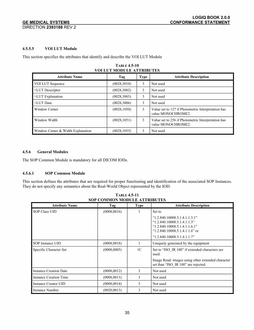
LOGIQ BOOK 2.0.0 GE MEDICAL SYSTEMS CONFORMANCE STATEMENT DIRECTION 2393188 REV 2
35
4.5.5.5 VOI LUT Module
This section specifies the attributes that identify and describe the VOI LUT Module
TABLE 4.5-10 VOI LUT MODULE ATTRIBUTES
Attribute Name Tag Type Attribute Description
VOI LUT Sequence (0028,3010) 3 Not used
>LUT Descriptor (0028,3002) 3 Not used
>LUT Explanation (0028,3003) 3 Not used
>LUT Data (0028,3006) 3 Not used
Window Center (0028,1050) 3 Value set to 127 if Photometric Interpretation has value MONOCHROME2.
Window Width (0028,1051) 3 Value set to 256 if Photometric Interpretation has value MONOCHROME2.
Window Center & Width Explanation (0028,1055) 3 Not used
4.5.6 General Modules
The SOP Common Module is mandatory for all DICOM IODs.
4.5.6.1 SOP Common Module
This section defines the attributes that are required for proper functioning and identification of the associated SOP Instances. They do not specify any semantics about the Real-World Object represented by the IOD.
TABLE 4.5-11 SOP COMMON MODULE ATTRIBUTES
Attribute Name Tag Type Attribute Description SOP Class UID (0008,0016) 1 Set to
“1.2.840.10008.5.1.4.1.1.3.1” “1.2.840.10008.5.1.4.1.1.3” “1.2.840.10008.5.1.4.1.1.6.1” “1.2.840.10008.5.1.4.1.1.6” or “1.2.840.10008.5.1.4.1.1.7”
SOP Instance UID (0008,0018) 1 Uniquely generated by the equipment
Specific Character Set (0008,0005) 1C Set to “ISO_IR 100” if extended characters are used. Image Read: images using other extended character set than “ISO_IR 100” are rejected.
Instance Creation Date (0008,0012) 3 Not used
Instance Creation Time (0008,0013) 3 Not used
Instance Creator UID (0008,0014) 3 Not used
Instance Number (0020,0013) 3 Not used

LOGIQ BOOK 2.0.0 GE MEDICAL SYSTEMS CONFORMANCE STATEMENT DIRECTION 2393188 REV 2
36
4.5.7 US Modules
This Section describes US Series, Equipment, and Image Modules. These Modules contain attributes that are specific to US Image IOD.
4.5.7.1 US Region Calibration Module
US Region Calibration Module is used to describe multiple regions. Note: if a multi-frame image has been acquired with different calibration, the US Region Calibration Module will not be used.
TABLE 4.5-12 US REGION CALIBRATION MODULE ATTRIBUTES
Attribute Name Tag Type Attribute Description
Sequence of Ultrasound Regions (0018,6011) 1 Object contains 0 or 1 regions
>Region Location Min x0 (0018,6018) 1 Value is 0
>Region Location Min y0 (0018,601A) 1 Value is 0
>Region Location Max x1 (0018,601C) 1 Value is image width-1.
>Region Location Max y1 (0018,601E) 1 Value is image height-1
>Physical Units X Direction (0018,6024) 1 Enumerated Values supported: 0003H cm 0004H seconds
>Physical Units Y Direction (0018,6026) 1 Enumerated Values supported: 0003H cm 0004H seconds 0007H cm/sec
>Physical Delta X (0018,602C) 1 Varies with scanning mode
>Physical Delta Y (0018,602E) 1 Varies with scanning mode
>Reference Pixel x0 (0018,6020) 3 Varies with scanning mode
>Reference Pixel y0 (0018,6022) 3 Varies with scanning mode
>Ref. Pixel Physical Value X (0018,6028) 3 Varies with scanning mode
>Ref. Pixel Physical Value Y (0018,602A) 3 Varies with scanning mode
>Region Spatial Format (0018,6012) 1 Supported. The spatial organization of the data within the region.
>Region Data Type (0018,6014) 1 Supported. The type of data within the region.
>Region Flags (0018,6016) 1 Bit 0: 0 = Opaque Bit 1: 0 = Not Protected because there may be other regions within the image Bit 2 : 0 = Velocity
>Pixel Component Organization (0018,6044) 1C Pixel component calibration data does not exist for any region
>Pixel Component Mask (0018,6046) 1C Not used
>Pixel Component Range Start (0018,6048) 1C Not used
>Pixel Component Range Stop (0018,604A) 1C Not used
>Pixel Component Physical Units (0018,604C) 1C Not used
>Pixel Component Data Type (0018,604E) 1C Not used
>Number of Table Break Points (0018,6050) 1C Not used
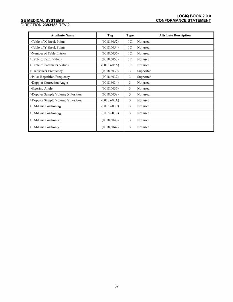
LOGIQ BOOK 2.0.0 GE MEDICAL SYSTEMS CONFORMANCE STATEMENT DIRECTION 2393188 REV 2
37
Attribute Name Tag Type Attribute Description
>Table of X Break Points (0018,6052) 1C Not used
>Table of Y Break Points (0018,6054) 1C Not used
>Number of Table Entries (0018,6056) 1C Not used
>Table of Pixel Values (0018,6058) 1C Not used
>Table of Parameter Values (0018,605A) 1C Not used
>Transducer Frequency (0018,6030) 3 Supported
>Pulse Repetition Frequency (0018,6032) 3 Supported
>Doppler Correction Angle (0018,6034) 3 Not used
>Steering Angle (0018,6036) 3 Not used
>Doppler Sample Volume X Position (0018,6038) 3 Not used
>Doppler Sample Volume Y Position (0018,603A) 3 Not used
>TM-Line Position x0 (0018,603C) 3 Not used
>TM-Line Position y0 (0018,603E) 3 Not used
>TM-Line Position x1 (0018,6040) 3 Not used
>TM-Line Position y1 (0018,6042) 3 Not used

LOGIQ BOOK 2.0.0 GE MEDICAL SYSTEMS CONFORMANCE STATEMENT DIRECTION 2393188 REV 2
38
4.5.7.2 US Image Module
This section specifies the attributes that describe ultrasound images.
TABLE 4.5-13 US IMAGE MODULE ATTRIBUTES
Attribute Name Tag Type Attribute Description
Samples Per Pixel (0028,0002) 1 Value of ‘1’ if Photometric Interpretation element value has value ‘MONOCHROME2’ Value of ‘3’ when Photometric Interpretation element value has value ‘RGB’ or 'YBR_FULL' or 'YBR_FULL_422'
Photometric Interpretation (0028,0004) 1 Defined Values used: “MONOCHROME2”, “RGB” , “YBR_FULL” or “YBR_FULL_422”
Bits Allocated (0028,0100) 1 Value always = 0008H
Bits Stored (0028,0101) 1 Value always = 0008H
High Bit (0028,0102) 1 Value always = 0007H
Planar Configuration (0028,0006) 1 Enumerated value 0000H, color-by-pixel, if Photometric Interpretation element value has value ‘RGB’ or if image is JPEG compressed. Enumerated value 0001H, color-by-plane if image is RLE compressed.
Pixel Representation (0028,0103) 1 Always 0000H = unsigned integer.
Frame Increment Pointer (0028,0009) 1C Export: Is set to Frame Time (0018,1063) or Frame Time Vector (0018,1065) if the image is multiframe IOD, Not used if the image is a single frame IOD.
Image Type (0008,0008) 2 The first two values contain “ORIGINAL/PRIMARY” or “DERIVED/ PRIMARY”. Value 4 is a description of the mode. Values 5 and 6 may be used for private data.
Lossy Image Compression (0028,2110) 1C Set to 01 if image is compressed using JPEG Baseline compression.
Number of Stages (0008,2124) 2C Number of stages in stress protocol. Sent if image is acquired in a stress test.
Number of Views in Stage (0008,212A) 2C Number of views in this stage of a stress protocol. Sent if image is acquired in a stress test.
Ultrasound Color Data Present (0028,0014) 3 Supported
Referenced Overlay Sequence (0008,1130) 3 Not used
>Referenced SOP Class UID (0008,1150) 1C Not used
>Referenced SOP Instance UID (0008,1155) 1C Not used
Referenced Curve Sequence (0008,1145) 3 Not used

LOGIQ BOOK 2.0.0 GE MEDICAL SYSTEMS CONFORMANCE STATEMENT DIRECTION 2393188 REV 2
39
Attribute Name Tag Type Attribute Description
>Referenced SOP Class UID (0008,1150) 1C Not used
>Referenced SOP Instance UID (0008,1155) 1C Not used
Stage Name (0008,2120) 3 Name of stage of stress test. Sent if image is acquired in a stress test. The name is defined in the User Interface.
Stage Number (0008,2122) 3 Number of stage, starting at one. Sent if image is acquired in a stress test.
View Name (0008,2127) 3 Name of view of stress test. Sent if image is acquired in a stress test. The name is defined in the User Interface.
View Number (0008,2128) 3 Number of view, starting at one. Sent if image is acquired in a stress test.
Number of Event Timers (0008,2129) 3 Not used
Event Elapsed Time(s) (0008,2130) 3 Not used
Event Timer Name(s) (0008,2132) 3 Not used
Anatomic Region Sequence (0008,2218) 3 Not used
>Include ‘Code Sequence Macro’
>Anatomic Region Modifier Sequence (0008,2220) 3 Not used
>>Include ‘Code Sequence Macro’
Primary Anatomic Structure Sequence (0008,2228) 3 Not used
>Include ‘Code Sequence Macro’
>Primary Anatomic Structure Modifier Sequence
(0008,2230) 3 Not used
>>Include ‘Code Sequence Macro’
Transducer Position Sequence (0008,2240) 3 Not used
>Include ‘Code Sequence Macro’
>Transducer Position Modifier Sequence (0008,2242) 3 Not used
>>Include ‘Code Sequence Macro’
Transducer Orientation Sequence (0008,2244) 3 Not used
>Include ‘Code Sequence Macro’
>Transducer Orientation Modifier Sequence (0008,2246) 3 Not used
>>Include ‘Code Sequence Macro’
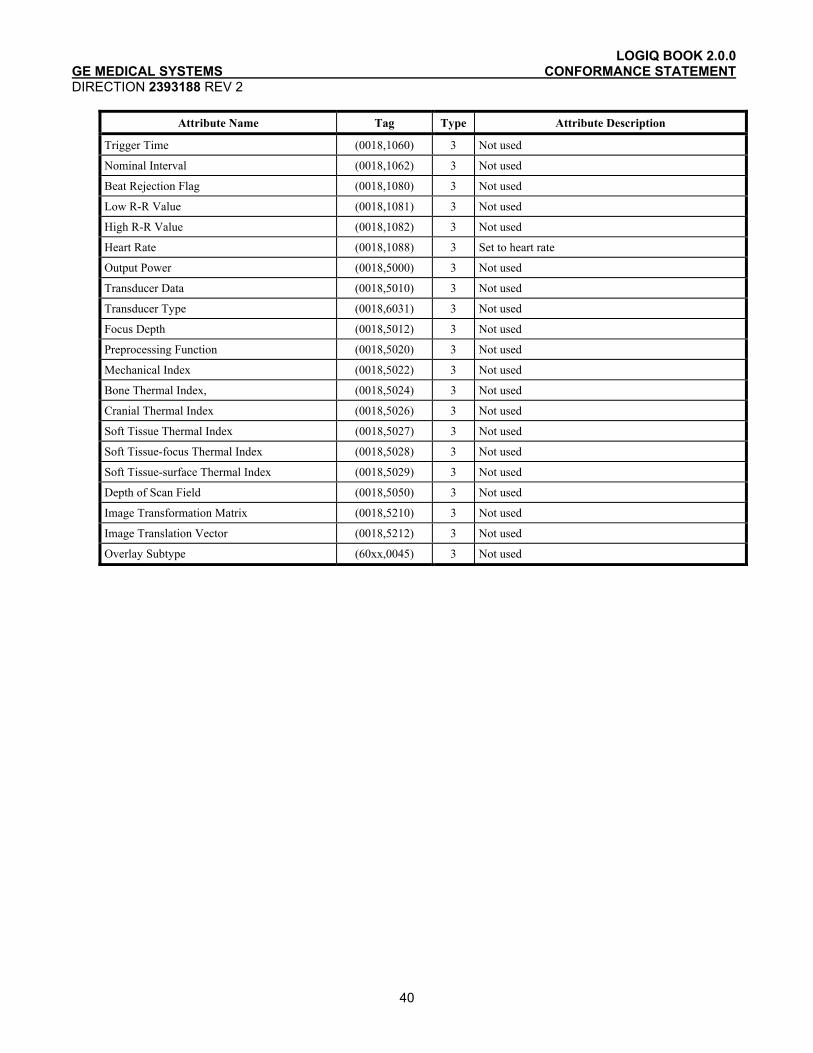
LOGIQ BOOK 2.0.0 GE MEDICAL SYSTEMS CONFORMANCE STATEMENT DIRECTION 2393188 REV 2
40
Attribute Name Tag Type Attribute Description
Trigger Time (0018,1060) 3 Not used
Nominal Interval (0018,1062) 3 Not used
Beat Rejection Flag (0018,1080) 3 Not used
Low R-R Value (0018,1081) 3 Not used
High R-R Value (0018,1082) 3 Not used
Heart Rate (0018,1088) 3 Set to heart rate
Output Power (0018,5000) 3 Not used
Transducer Data (0018,5010) 3 Not used
Transducer Type (0018,6031) 3 Not used
Focus Depth (0018,5012) 3 Not used
Preprocessing Function (0018,5020) 3 Not used
Mechanical Index (0018,5022) 3 Not used
Bone Thermal Index, (0018,5024) 3 Not used
Cranial Thermal Index (0018,5026) 3 Not used
Soft Tissue Thermal Index (0018,5027) 3 Not used
Soft Tissue-focus Thermal Index (0018,5028) 3 Not used
Soft Tissue-surface Thermal Index (0018,5029) 3 Not used
Depth of Scan Field (0018,5050) 3 Not used
Image Transformation Matrix (0018,5210) 3 Not used
Image Translation Vector (0018,5212) 3 Not used
Overlay Subtype (60xx,0045) 3 Not used
LOGIQ BOOK R2.0.0 GE MEDICAL SYSTEMS CONFORMANCE STATEMENT DIRECTION 2393188 REV 2
41
5. ULTRASOUND MULTIFRAME (US MF) INFORMATION OBJECT IMPLEMENTATION
5.1 INTRODUCTION
This section specifies the use of the DICOM US Multi-frame Image IOD to represent the information included in US images produced by this implementation. Corresponding attributes are conveyed using the module construct. The contents of this section are:
5.2 - IOD Implementation
5.3 - IOD Entity-Relationship Model
5.4 - IOD Module Table
5.5 - IOD Module Definition
5.2 US MF IOD IMPLEMENTATION
This section defines the implementation of US Multi-Frame image information object.
5.3 US MF ENTITY-RELATIONSHIP MODEL
The Entity-Relationship diagram for the US MF Image interoperability schema is shown in Illustration 5.3-1. In this figure, the following diagrammatic convention is established to represent the information organization:
• each entity is represented by a rectangular box • each relationship is represented by a diamond shaped box. • the fact that a relationship exists between two entities is depicted by lines connecting the corresponding
entity boxes to the relationship boxes.
The relationships are fully defined with the maximum number of possible entities in the relationship shown. In other words, the relationship between Series and Image can have up to n Images per Series, but the Patient to Study relationship has 1 Study for each Patient (a Patient can have more than one Study on the system, however each Study will contain all of the information pertaining to that Patient).

LOGIQ BOOK R2.0.0 GE MEDICAL SYSTEMS CONFORMANCE STATEMENT DIRECTION 2393188 REV 2
42
ILLUSTRATION 5.3-1 US MULTIFRAME IMAGE ENTITY RELATIONSHIP DIAGRAM
Patient
Study
is the subject
of
contains
creates
Equipment
US MF Image
contains
Series
0,n
1 1 1,n
1,n
1
1,n
1
5.3.1 Entity Descriptions
Please refer to DICOM Standard Part 3 (Information Object Definitions) for a description of each of the entities contained within the US Multi-Frame Information Object.
5.3.2 LOGIQ BOOK Mapping of DICOM entities
TABLE 5.3-1 MAPPING OF DICOM ENTITIES TO LOGIQ BOOK ENTITIES
DICOM LOGIQ BOOK Entity
Patient Patient
Study Exam
Series Exam
Image Image
Curve Not used

LOGIQ BOOK R2.0.0 GE MEDICAL SYSTEMS CONFORMANCE STATEMENT DIRECTION 2393188 REV 2
43
5.4 IOD MODULE TABLE
Within an entity of the DICOM US Multi-Frame IOD, attributes are grouped into related set of attributes. A set of related attributes is termed a module. A module facilitates the understanding of the semantics concerning the attributes and how the attributes are related with each other. A module grouping does not infer any encoding of information into datasets.
Table 5.4-1 identifies the defined modules within the entities, which comprise the DICOM US Multi-Frame IOD. Modules are identified by Module Name.
See DICOM Part 3 for a complete definition of the entities, modules, and attributes.
TABLE 5.4-1 US MULTI-FRAME IOD MODULES Entity Name Module Name Reference
Patient Patient 4.5.1.1
Study General Study 4.5.2.1
Patient Study 4.5.2.2
Series General Series 4.5.3.1
Frame of Reference Frame of Reference Not used
US Frame of Reference Not used
Equipment General Equipment 4.5.4.1
Image General Image 4.5.5.1
Image Pixel 4.5.5.2
Contrast/Bolus 4.5.5.3
Cine 5.5.1.1
Multi-frame 5.5.1.2
Palette Color Lookup Table 4.5.5.4
US Region Calibration 4.5.7.1
US Image 4.5.7.2
Overlay Plane Not used
VOI LUT 4.5.5.5
SOP Common 4.5.6.1
Curve Not used
5.5 INFORMATION MODULE DEFINITIONS
Please refer to DICOM Standard Part 3 (Information Object Definitions) for a description of each of the entities and modules contained within the US Multi-Frame Information Object.
The following modules are included to convey Enumerated Values, Defined Terms, and Optional Attributes supported. Type 1 & Type 2 Attributes are also included for completeness and to define what values they may take and where these values are

LOGIQ BOOK R2.0.0 GE MEDICAL SYSTEMS CONFORMANCE STATEMENT DIRECTION 2393188 REV 2
44
obtained. It should be noted that they are the same ones as defined in the DICOM Standard Part 3 (Information Object Definitions).
5.5.1 Common Image Modules
The following Image IE Modules are common to all Composite Image IODs which reference the Image IE.
5.5.1.1 Cine Module
TABLE 5.5-2 CINE MODULE ATTRIBUTES
Attribute Name Tag Type Attribute Description Frame Time (0018,1063) 1C Is set to the interframe time
Frame Time Vector (0018,1065) 1C Supported. Reading: Average value is set to interframe time
Start Trim (0008,2142) 3 Supported
Stop Trim (0008,2143) 3 Supported
Recommended Display Frame Rate (0008,2144) 3 Supported
Cine Rate (0018,0040) 3 Supported
Frame Delay (0018,1066) 3 Supported
Effective Duration (0018,0072) 3 Supported
Actual Frame Duration (0018,1242) 3 Supported
Preferred Playback Sequencing (0018,1244) 3 Supported
5.5.1.2 Multi-frame Module
TABLE 5.5-3 MULTI-FRAME MODULE ATTRIBUTES
Attribute Name Tag Type Attribute Description Number of Frames (0028,0008) 1 Is set to the number of frames in
image
Frame Increment Pointer (0028,0009) 1 Is set to Frame Time (0018,1063) or Frame Time Vector (0018,1065)

LOGIQ BOOK R2.0.0 GE MEDICAL SYSTEMS CONFORMANCE STATEMENT DIRECTION 2393188 REV 2
45

LOGIQ BOOK R2.0.0 GE MEDICAL SYSTEMS CONFORMANCE STATEMENT DIRECTION 2393188 REV 2
46
6. SC INFORMATION OBJECT IMPLEMENTATION
6.1 INTRODUCTION
This section specifies the use of the DICOM SC Image IOD to represent the information included in SC images produced by this implementation. Corresponding attributes are conveyed using the module construct. The contents of this section are:
6.2 - IOD Implementation
6.3 - IOD Entity-Relationship Model
6.4 - IOD Module Table
6.5 - IOD Module Definition
6.2 SC IOD IMPLEMENTATION
This section defines the implementation of SC image information object.
6.3 SC ENTITY-RELATIONSHIP MODEL
The Entity-Relationship diagram for the SC Image interoperability schema is shown in Illustration 6.3-1. In this figure, the following diagrammatic convention is established to represent the information organization:
• each entity is represented by a rectangular box • each relationship is represented by a diamond shaped box. • the fact that a relationship exists between two entities is depicted by lines connecting the
corresponding entity boxes to the relationship boxes.
The relationships are fully defined with the maximum number of possible entities in the relationship shown. In other words, the relationship between Series and Image can have up to n Images per Series, but the Patient to Study relationship has 1 Study for each Patient (a Patient can have more than one Study on the system, however each Study will contain all of the information pertaining to that Patient).

LOGIQ BOOK R2.0.0 GE MEDICAL SYSTEMS CONFORMANCE STATEMENT DIRECTION 2393188 REV 2
47
ILLUSTRATION 6.3-1 SC IMAGE ENTITY RELATIONSHIP DIAGRAM
Patient
Study
is the subject
of
contains
creates
Equipment
SC Image
contains
Series
0,n
1 1 1,n
1,n
1
1,n
1
6.3.1 Entity Descriptions
Please refer to DICOM Standard Part 3 (Information Object Definitions) for a description of each of the entities contained within the SC Information Object.
6.3.2 LOGIQ BOOK Mapping of DICOM Entities
TABLE 6.3-1 MAPPING OF DICOM ENTITIES TO LOGIQ BOOK ENTITIES
DICOM LOGIQ BOOK Entity
Patient Patient
Study Exam
Series Exam
Image Image
Frame Not Applicable
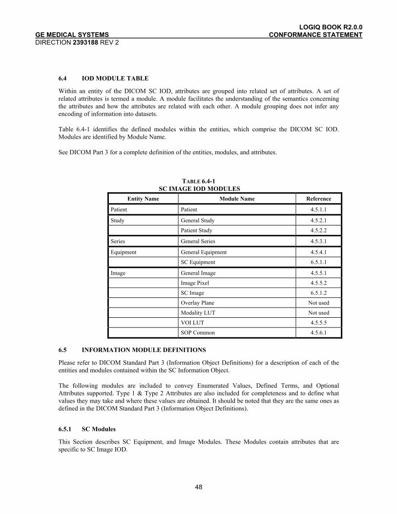
LOGIQ BOOK R2.0.0 GE MEDICAL SYSTEMS CONFORMANCE STATEMENT DIRECTION 2393188 REV 2
48
6.4 IOD MODULE TABLE
Within an entity of the DICOM SC IOD, attributes are grouped into related set of attributes. A set of related attributes is termed a module. A module facilitates the understanding of the semantics concerning the attributes and how the attributes are related with each other. A module grouping does not infer any encoding of information into datasets.
Table 6.4-1 identifies the defined modules within the entities, which comprise the DICOM SC IOD. Modules are identified by Module Name.
See DICOM Part 3 for a complete definition of the entities, modules, and attributes.
TABLE 6.4-1 SC IMAGE IOD MODULES
Entity Name Module Name Reference
Patient Patient 4.5.1.1
Study General Study 4.5.2.1
Patient Study 4.5.2.2
Series General Series 4.5.3.1
Equipment General Equipment 4.5.4.1
SC Equipment 6.5.1.1
Image General Image 4.5.5.1
Image Pixel 4.5.5.2
SC Image 6.5.1.2
Overlay Plane Not used
Modality LUT Not used
VOI LUT 4.5.5.5
SOP Common 4.5.6.1
6.5 INFORMATION MODULE DEFINITIONS
Please refer to DICOM Standard Part 3 (Information Object Definitions) for a description of each of the entities and modules contained within the SC Information Object.
The following modules are included to convey Enumerated Values, Defined Terms, and Optional Attributes supported. Type 1 & Type 2 Attributes are also included for completeness and to define what values they may take and where these values are obtained. It should be noted that they are the same ones as defined in the DICOM Standard Part 3 (Information Object Definitions).
6.5.1 SC Modules
This Section describes SC Equipment, and Image Modules. These Modules contain attributes that are specific to SC Image IOD.
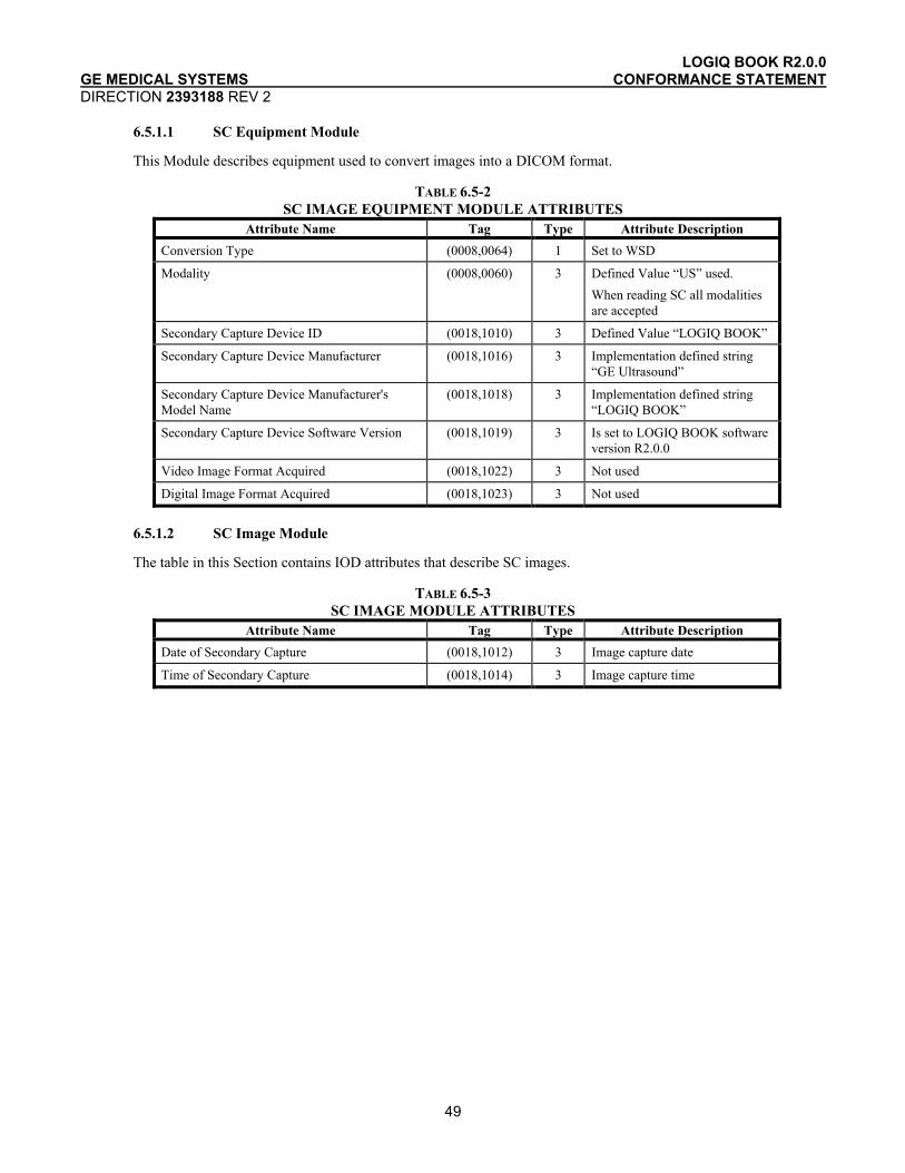
LOGIQ BOOK R2.0.0 GE MEDICAL SYSTEMS CONFORMANCE STATEMENT DIRECTION 2393188 REV 2
49
6.5.1.1 SC Equipment Module
This Module describes equipment used to convert images into a DICOM format.
TABLE 6.5-2 SC IMAGE EQUIPMENT MODULE ATTRIBUTES
Attribute Name Tag Type Attribute Description Conversion Type (0008,0064) 1 Set to WSD
Modality (0008,0060) 3 Defined Value “US” used. When reading SC all modalities are accepted
Secondary Capture Device ID (0018,1010) 3 Defined Value “LOGIQ BOOK”
Secondary Capture Device Manufacturer (0018,1016) 3 Implementation defined string “GE Ultrasound”
Secondary Capture Device Manufacturer's Model Name
(0018,1018) 3 Implementation defined string “LOGIQ BOOK”
Secondary Capture Device Software Version (0018,1019) 3 Is set to LOGIQ BOOK software version R2.0.0
Video Image Format Acquired (0018,1022) 3 Not used
Digital Image Format Acquired (0018,1023) 3 Not used
6.5.1.2 SC Image Module
The table in this Section contains IOD attributes that describe SC images.
TABLE 6.5-3 SC IMAGE MODULE ATTRIBUTES
Attribute Name Tag Type Attribute Description Date of Secondary Capture (0018,1012) 3 Image capture date
Time of Secondary Capture (0018,1014) 3 Image capture time
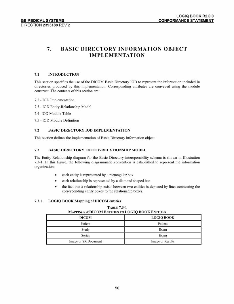
LOGIQ BOOK R2.0.0 GE MEDICAL SYSTEMS CONFORMANCE STATEMENT DIRECTION 2393188 REV 2
50
7. BASIC DIRECTORY INFORMATION OBJECT IMPLEMENTATION
7.1 INTRODUCTION
This section specifies the use of the DICOM Basic Directory IOD to represent the information included in directories produced by this implementation. Corresponding attributes are conveyed using the module construct. The contents of this section are:
7.2 - IOD Implementation
7.3 - IOD Entity-Relationship Model
7.4- IOD Module Table
7.5 - IOD Module Definition
7.2 BASIC DIRECTORY IOD IMPLEMENTATION
This section defines the implementation of Basic Directory information object.
7.3 BASIC DIRECTORY ENTITY-RELATIONSHIP MODEL
The Entity-Relationship diagram for the Basic Directory interoperability schema is shown in Illustration 7.3-1. In this figure, the following diagrammatic convention is established to represent the information organization:
• each entity is represented by a rectangular box • each relationship is represented by a diamond shaped box • the fact that a relationship exists between two entities is depicted by lines connecting the
corresponding entity boxes to the relationship boxes.
7.3.1 LOGIQ BOOK Mapping of DICOM entities
TABLE 7.3-1 MAPPING OF DICOM ENTITIES TO LOGIQ BOOK ENTITIES
DICOM LOGIQ BOOK
Patient Patient
Study Exam
Series Exam
Image or SR Document Image or Results

LOGIQ BOOK R2.0.0 GE MEDICAL SYSTEMS CONFORMANCE STATEMENT DIRECTION 2393188 REV 2
51
ILLUSTRATION 7.3-1 BASIC DIRECTORY ENTITY RELATIONSHIP DIAGRAM
Root Directory Entity
Patient DR
Includes
1
0 - n
*
Study DR
*
1 - n
Series DR
*
1
Image or Report DR
1 - n
1
1
1
7.4 IOD MODULE TABLE
Within an entity of the Basic Directory IOD, attributes are grouped into related set of attributes. A set of related attributes is termed a module. A module facilitates the understanding of the semantics concerning the attributes and how the attributes are related with each other. A module grouping does not infer any encoding of information into datasets.
Table 7.4-1 identifies the defined modules within the entities, which comprise the Basic Directory IOD. Modules are identified by Module Name.
See DICOM Part 3 for a complete definition of the entities, modules, and attributes.
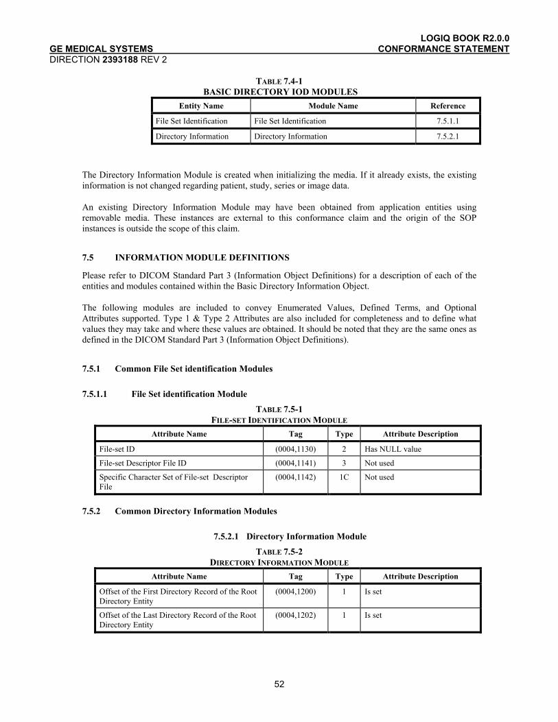
LOGIQ BOOK R2.0.0 GE MEDICAL SYSTEMS CONFORMANCE STATEMENT DIRECTION 2393188 REV 2
52
TABLE 7.4-1 BASIC DIRECTORY IOD MODULES
Entity Name Module Name Reference
File Set Identification File Set Identification 7.5.1.1
Directory Information Directory Information 7.5.2.1
The Directory Information Module is created when initializing the media. If it already exists, the existing information is not changed regarding patient, study, series or image data.
An existing Directory Information Module may have been obtained from application entities using removable media. These instances are external to this conformance claim and the origin of the SOP instances is outside the scope of this claim.
7.5 INFORMATION MODULE DEFINITIONS
Please refer to DICOM Standard Part 3 (Information Object Definitions) for a description of each of the entities and modules contained within the Basic Directory Information Object.
The following modules are included to convey Enumerated Values, Defined Terms, and Optional Attributes supported. Type 1 & Type 2 Attributes are also included for completeness and to define what values they may take and where these values are obtained. It should be noted that they are the same ones as defined in the DICOM Standard Part 3 (Information Object Definitions).
7.5.1 Common File Set identification Modules
7.5.1.1 File Set identification Module
TABLE 7.5-1 FILE-SET IDENTIFICATION MODULE
Attribute Name Tag Type Attribute Description
File-set ID (0004,1130) 2 Has NULL value
File-set Descriptor File ID (0004,1141) 3 Not used
Specific Character Set of File-set Descriptor File
(0004,1142) 1C Not used
7.5.2 Common Directory Information Modules
7.5.2.1 Directory Information Module
TABLE 7.5-2 DIRECTORY INFORMATION MODULE
Attribute Name Tag Type Attribute Description
Offset of the First Directory Record of the Root Directory Entity
(0004,1200) 1 Is set
Offset of the Last Directory Record of the Root Directory Entity
(0004,1202) 1 Is set
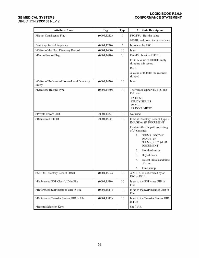
LOGIQ BOOK R2.0.0 GE MEDICAL SYSTEMS CONFORMANCE STATEMENT DIRECTION 2393188 REV 2
53
Attribute Name Tag Type Attribute Description
File-set Consistency Flag (0004,1212) 1 FSC/FSU: Has the value 0000H: no known inconsistencies
Directory Record Sequence (0004,1220) 2 Is created by FSC
>Offset of the Next Directory Record (0004,1400) 1C Is set
>Record In-use Flag (0004,1410) 1C FSC/FS: Is set to FFFFH FSR: A value of 0000H: imply skipping this record Read: A value of 0000H: the record is skipped
>Offset of Referenced Lower-Level Directory Entity
(0004,1420) 1C Is set
>Directory Record Type (0004,1430) 1C The values support by FSC and FSU are PATIENT STUDY SERIES IMAGE SR DOCUMENT
>Private Record UID (0004,1432) 1C Not used
>Referenced File ID (0004,1500) 1C Is set if Directory Record Type is IMAGE or SR DOCUMENT Contains the file path consisting of 5 elements:
1. “GEMS_IMG” (if IMAGE) or “GEMS_REP” (if SR DOCUMENT)
2. Month of exam 3. Day of exam 4. Patient initials and time
of exam 5. Time stamp
>MRDR Directory Record Offset (0004,1504) 1C A MRDR is not created by an FSC or FSU.
>Referenced SOP Class UID in File (0004,1510) 1C Is set to the SOP class UID in File
>Referenced SOP Instance UID in File (0004,1511) 1C Is set to the SOP instance UID in File
>Referenced Transfer Syntax UID in File (0004,1512) 1C Is set to the Transfer Syntax UID in File
>Record Selection Keys See 7.5.3.
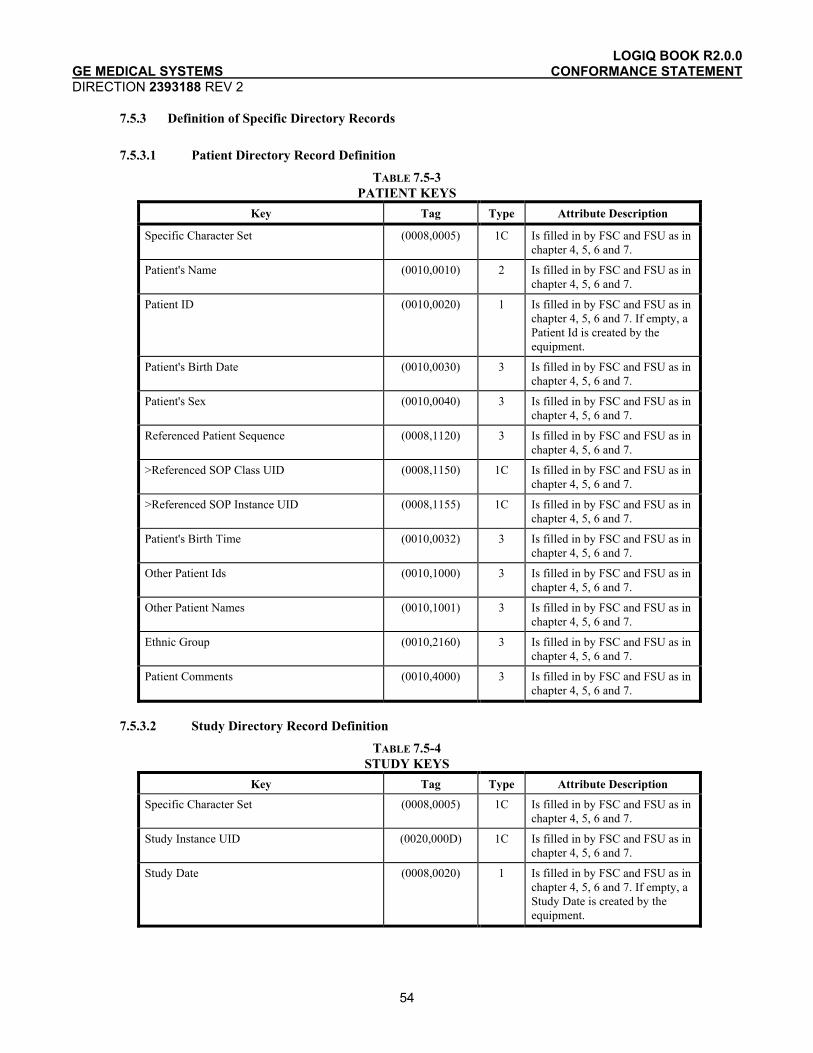
LOGIQ BOOK R2.0.0 GE MEDICAL SYSTEMS CONFORMANCE STATEMENT DIRECTION 2393188 REV 2
54
7.5.3 Definition of Specific Directory Records
7.5.3.1 Patient Directory Record Definition TABLE 7.5-3
PATIENT KEYS Key Tag Type Attribute Description
Specific Character Set (0008,0005) 1C Is filled in by FSC and FSU as in chapter 4, 5, 6 and 7.
Patient's Name (0010,0010) 2 Is filled in by FSC and FSU as in chapter 4, 5, 6 and 7.
Patient ID (0010,0020) 1 Is filled in by FSC and FSU as in chapter 4, 5, 6 and 7. If empty, a Patient Id is created by the equipment.
Patient's Birth Date (0010,0030) 3 Is filled in by FSC and FSU as in chapter 4, 5, 6 and 7.
Patient's Sex (0010,0040) 3 Is filled in by FSC and FSU as in chapter 4, 5, 6 and 7.
Referenced Patient Sequence (0008,1120) 3 Is filled in by FSC and FSU as in chapter 4, 5, 6 and 7.
>Referenced SOP Class UID (0008,1150) 1C Is filled in by FSC and FSU as in chapter 4, 5, 6 and 7.
>Referenced SOP Instance UID (0008,1155) 1C Is filled in by FSC and FSU as in chapter 4, 5, 6 and 7.
Patient's Birth Time (0010,0032) 3 Is filled in by FSC and FSU as in chapter 4, 5, 6 and 7.
Other Patient Ids (0010,1000) 3 Is filled in by FSC and FSU as in chapter 4, 5, 6 and 7.
Other Patient Names (0010,1001) 3 Is filled in by FSC and FSU as in chapter 4, 5, 6 and 7.
Ethnic Group (0010,2160) 3 Is filled in by FSC and FSU as in chapter 4, 5, 6 and 7.
Patient Comments (0010,4000) 3 Is filled in by FSC and FSU as in chapter 4, 5, 6 and 7.
7.5.3.2 Study Directory Record Definition
TABLE 7.5-4 STUDY KEYS
Key Tag Type Attribute Description
Specific Character Set (0008,0005) 1C Is filled in by FSC and FSU as in chapter 4, 5, 6 and 7.
Study Instance UID (0020,000D) 1C Is filled in by FSC and FSU as in chapter 4, 5, 6 and 7.
Study Date (0008,0020) 1 Is filled in by FSC and FSU as in chapter 4, 5, 6 and 7. If empty, a Study Date is created by the equipment.

LOGIQ BOOK R2.0.0 GE MEDICAL SYSTEMS CONFORMANCE STATEMENT DIRECTION 2393188 REV 2
55
Key Tag Type Attribute Description
Study Time (0008,0030) 1 Is filled in by FSC and FSU as in chapter 4, 5, 6 and 7. If empty, a Study Time is created by the equipment.
Referring Physician's Name (0008,0090) 2 Is filled in by FSC and FSU as in chapter 4, 5, 6 and 7.
Study ID (0020,0010) 1 Is filled in by FSC and FSU as in chapter 4, 5, 6 and 7. If empty, a Study Id is created by the equipment.
Accession Number (0008,0050) 2 Is filled in by FSC and FSU as in chapter 4, 5, 6 and 7.
Study Description (0008,1030) 2 Is filled in by FSC and FSU as in chapter 4, 5, 6 and 7.
Physician(s) of Record (0008,1048) 3 Is filled in by FSC and FSU as in chapter 4, 5, 6 and 7.
Name of Physician(s) Reading Study (0008,1060) 3 Is filled in by FSC and FSU as in chapter 4, 5, 6 and 7.
Referenced Study Sequence (0008,1110) 3 Is filled in by FSC and FSU as in chapter 4, 5, 6 and 7.
>Referenced SOP Class UID (0008,1150) 1C Is filled in by FSC and FSU as in chapter 4, 5, 6 and 7.
>Referenced SOP Instance UID (0008,1155) 1C Is filled in by FSC and FSU as in chapter 4, 5, 6 and 7.
Admitting Diagnoses Description (0008,1080) 3 Is filled in by FSC and FSU as in chapter 4, 5, 6 and 7.
Patient's Age (0010,1010) 3 Is filled in by FSC and FSU as in chapter 4, 5, 6 and 7.
Patient's Size (0010,1020) 3 Is filled in by FSC and FSU as in chapter 4, 5, 6 and 7.
Patient's Weight (0010,1030) 3 Is filled in by FSC and FSU as in chapter 4, 5, 6 and 7.
Occupation (0010,2180) 3 Is filled in by FSC and FSU as in chapter 4, 5, 6 and 7.
Additional Patient’s History (0010,21B0) 3 Is filled in by FSC and FSU as in chapter 4, 5, 6 and 7.
7.5.3.3 Series Directory Record Definition
TABLE 7.5-5 SERIES KEYS
Key Tag Type Attribute Description
Specific Character Set (0008,0005) 1C Is filled in by FSC or FSU as contained in the image or SR document message, if one of the tags contains extended characters
Modality (0008,0060) 1 Is filled in by FSC and FSU as in chapter 4, 5, 6 and 7.
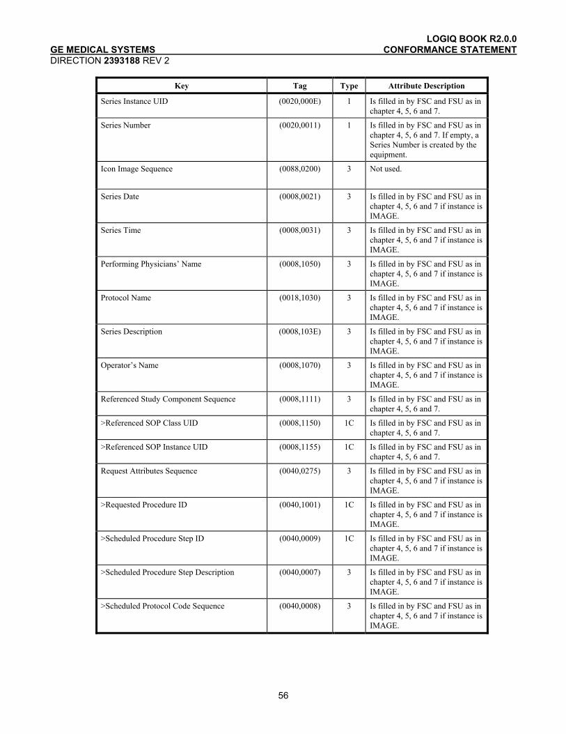
LOGIQ BOOK R2.0.0 GE MEDICAL SYSTEMS CONFORMANCE STATEMENT DIRECTION 2393188 REV 2
56
Key Tag Type Attribute Description
Series Instance UID (0020,000E) 1 Is filled in by FSC and FSU as in chapter 4, 5, 6 and 7.
Series Number (0020,0011) 1 Is filled in by FSC and FSU as in chapter 4, 5, 6 and 7. If empty, a Series Number is created by the equipment.
Icon Image Sequence (0088,0200) 3 Not used.
Series Date (0008,0021) 3 Is filled in by FSC and FSU as in chapter 4, 5, 6 and 7 if instance is IMAGE.
Series Time (0008,0031) 3 Is filled in by FSC and FSU as in chapter 4, 5, 6 and 7 if instance is IMAGE.
Performing Physicians’ Name (0008,1050) 3 Is filled in by FSC and FSU as in chapter 4, 5, 6 and 7 if instance is IMAGE.
Protocol Name (0018,1030) 3 Is filled in by FSC and FSU as in chapter 4, 5, 6 and 7 if instance is IMAGE.
Series Description (0008,103E) 3 Is filled in by FSC and FSU as in chapter 4, 5, 6 and 7 if instance is IMAGE.
Operator’s Name (0008,1070) 3 Is filled in by FSC and FSU as in chapter 4, 5, 6 and 7 if instance is IMAGE.
Referenced Study Component Sequence (0008,1111) 3 Is filled in by FSC and FSU as in chapter 4, 5, 6 and 7.
>Referenced SOP Class UID (0008,1150) 1C Is filled in by FSC and FSU as in chapter 4, 5, 6 and 7.
>Referenced SOP Instance UID (0008,1155) 1C Is filled in by FSC and FSU as in chapter 4, 5, 6 and 7.
Request Attributes Sequence (0040,0275) 3 Is filled in by FSC and FSU as in chapter 4, 5, 6 and 7 if instance is IMAGE.
>Requested Procedure ID (0040,1001) 1C Is filled in by FSC and FSU as in chapter 4, 5, 6 and 7 if instance is IMAGE.
>Scheduled Procedure Step ID (0040,0009) 1C Is filled in by FSC and FSU as in chapter 4, 5, 6 and 7 if instance is IMAGE.
>Scheduled Procedure Step Description (0040,0007) 3 Is filled in by FSC and FSU as in chapter 4, 5, 6 and 7 if instance is IMAGE.
>Scheduled Protocol Code Sequence (0040,0008) 3 Is filled in by FSC and FSU as in chapter 4, 5, 6 and 7 if instance is IMAGE.
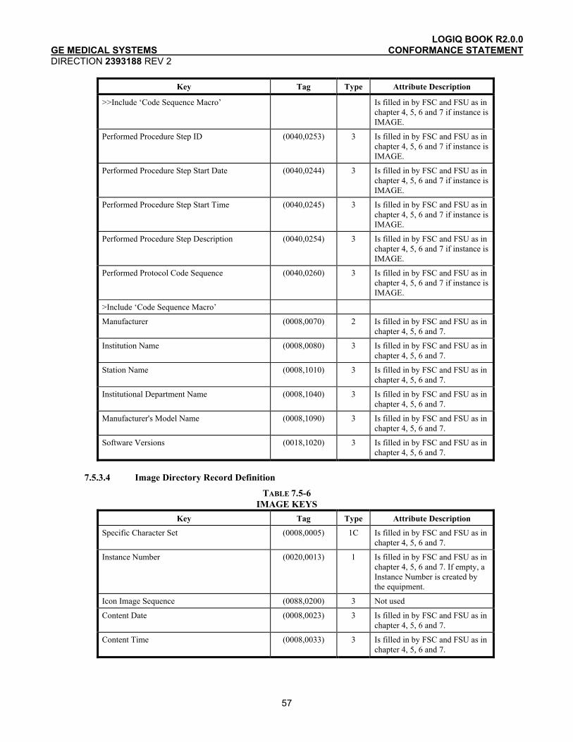
LOGIQ BOOK R2.0.0 GE MEDICAL SYSTEMS CONFORMANCE STATEMENT DIRECTION 2393188 REV 2
57
Key Tag Type Attribute Description
>>Include ‘Code Sequence Macro’ Is filled in by FSC and FSU as in chapter 4, 5, 6 and 7 if instance is IMAGE.
Performed Procedure Step ID (0040,0253) 3 Is filled in by FSC and FSU as in chapter 4, 5, 6 and 7 if instance is IMAGE.
Performed Procedure Step Start Date (0040,0244) 3 Is filled in by FSC and FSU as in chapter 4, 5, 6 and 7 if instance is IMAGE.
Performed Procedure Step Start Time (0040,0245) 3 Is filled in by FSC and FSU as in chapter 4, 5, 6 and 7 if instance is IMAGE.
Performed Procedure Step Description (0040,0254) 3 Is filled in by FSC and FSU as in chapter 4, 5, 6 and 7 if instance is IMAGE.
Performed Protocol Code Sequence (0040,0260) 3 Is filled in by FSC and FSU as in chapter 4, 5, 6 and 7 if instance is IMAGE.
>Include ‘Code Sequence Macro’
Manufacturer (0008,0070) 2 Is filled in by FSC and FSU as in chapter 4, 5, 6 and 7.
Institution Name (0008,0080) 3 Is filled in by FSC and FSU as in chapter 4, 5, 6 and 7.
Station Name (0008,1010) 3 Is filled in by FSC and FSU as in chapter 4, 5, 6 and 7.
Institutional Department Name (0008,1040) 3 Is filled in by FSC and FSU as in chapter 4, 5, 6 and 7.
Manufacturer's Model Name (0008,1090) 3 Is filled in by FSC and FSU as in chapter 4, 5, 6 and 7.
Software Versions (0018,1020) 3 Is filled in by FSC and FSU as in chapter 4, 5, 6 and 7.
7.5.3.4 Image Directory Record Definition
TABLE 7.5-6 IMAGE KEYS
Key Tag Type Attribute Description
Specific Character Set (0008,0005) 1C Is filled in by FSC and FSU as in chapter 4, 5, 6 and 7.
Instance Number (0020,0013) 1 Is filled in by FSC and FSU as in chapter 4, 5, 6 and 7. If empty, a Instance Number is created by the equipment.
Icon Image Sequence (0088,0200) 3 Not used
Content Date (0008,0023) 3 Is filled in by FSC and FSU as in chapter 4, 5, 6 and 7.
Content Time (0008,0033) 3 Is filled in by FSC and FSU as in chapter 4, 5, 6 and 7.

LOGIQ BOOK R2.0.0 GE MEDICAL SYSTEMS CONFORMANCE STATEMENT DIRECTION 2393188 REV 2
58
Image Type (0008,0008) 3 Is filled in by FSC and FSU as in chapter 4, 5, 6 and 7.
Rows (0028,0010) 3 Is filled in by FSC and FSU as in chapter 4, 5, 6 and 7.
Columns (0028,0011) 3 Is filled in by FSC and FSU as in chapter 4, 5, 6 and 7.
Number Of Frames (0028,0008) 3 Is filled in by FSC and FSU as in chapter 4, 5, 6 and 7.
Photometric Interpretation (0028,0004) 3 Is filled in by FSC and FSU as in chapter 4, 5, 6 and 7.
Referenced Transfer Syntax UID in File (0004,1512) 3 Is set to the Transfer Syntax UID in File
Referenced SOP Instance UID in File (0004,1511) 3 Is set to the SOP instance UID in File
Referenced SOP Class in File (0004,1510) 3 Is set to the SOP class UID in File
Contrast/Bolus Agent (0018,0010) 2 Is filled in by FSC and FSU as in chapter 4, 5, 6 and 7.
Lossy Image Compression (0028,2110) 3 Is filled in by FSC and FSU as in chapter 4, 5, 6 and 7.
Lossy Image Compression Ratio (0028,2112) 3 Is filled in by FSC and FSU as in chapter 4, 5, 6 and 7.
7.5.3.5 Report Directory Record Definition
TABLE 7.5-7 REPORT KEYS
Key Tag Type Attribute Description
Specific Character Set (0008,0005) 1C Is filled in by FSC and FSU as in chapter 4, 5, 6 and 7.
Instance Number (0020,0013) 1 Is filled in by FSC and FSU as in chapter 4, 5, 6 and 7. If empty, a Instance Number is created by the equipment.
Content Date (0008,0023) 3 Is filled in by FSC and FSU as in chapter 4, 5, 6 and 7.
Content Time (0008,0033) 3 Is filled in by FSC and FSU as in chapter 4, 5, 6 and 7.
Referenced Transfer Syntax UID in File (0004,1512) 3 Is set to the Transfer Syntax UID in File
Referenced SOP Instance UID in File (0004,1511) 3 Is set to the SOP instance UID in File
Referenced SOP Class in File (0004,1510) 3 Is set to the SOP class UID in File
Completion Flag (0040,A491) 3 Is filled in by FSC and FSU as in chapter 4, 5, 6 and 7.
Verification Flag (0040,A493) 3 Is filled in by FSC and FSU as in chapter 4, 5, 6 and 7.
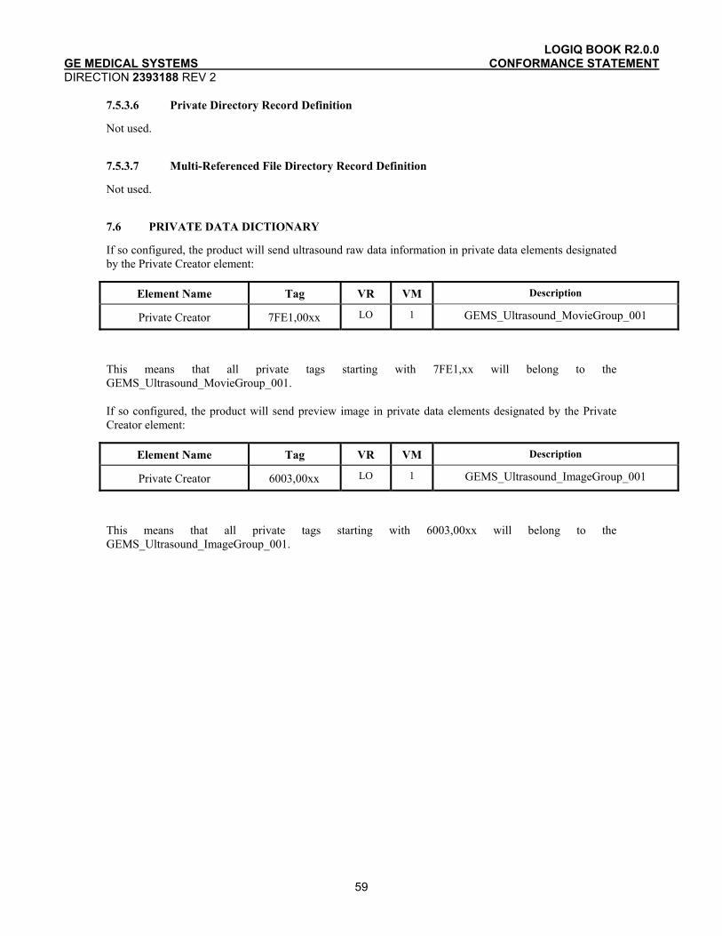
LOGIQ BOOK R2.0.0 GE MEDICAL SYSTEMS CONFORMANCE STATEMENT DIRECTION 2393188 REV 2
59
7.5.3.6 Private Directory Record Definition
Not used.
7.5.3.7 Multi-Referenced File Directory Record Definition
Not used.
7.6 PRIVATE DATA DICTIONARY
If so configured, the product will send ultrasound raw data information in private data elements designated by the Private Creator element:
Element Name Tag VR VM Description
Private Creator 7FE1,00xx LO 1 GEMS_Ultrasound_MovieGroup_001
This means that all private tags starting with 7FE1,xx will belong to the GEMS_Ultrasound_MovieGroup_001.
If so configured, the product will send preview image in private data elements designated by the Private Creator element:
Element Name Tag VR VM Description
Private Creator 6003,00xx LO 1 GEMS_Ultrasound_ImageGroup_001
This means that all private tags starting with 6003,00xx will belong to the GEMS_Ultrasound_ImageGroup_001.

LOGIQ BOOK R2.0.0 GE MEDICAL SYSTEMS CONFORMANCE STATEMENT DIRECTION 2393188 REV 2
60
8. MODALITY WORKLIST INFORMATION MODEL DEFINITION
8.1 INTRODUCTION
This section specifies the use of the DICOM Modality Worklist Information Model used to organize data and against which a Modality Worklist Query will be performed. The contents of this section are:
8.2- Information Model Description
8.3- Information Model Entity-Relationship Model
8.4- Information Model Module Table
8.5- Information Model Keys
8.2 MODALITY WORKLIST INFORMATION MODEL DESCRIPTION
This section defines the implementation of Modality Worklist Information Model.
8.3 MODALITY WORKLIST INFORMATION MODEL ENTITY-RELATIONSHIP MODEL
The Entity-Relationship diagram for the Modality Worklist Information Model schema is shown in Illustration 9.3-1. It represents the information that composes a Worklist Item. In this figure, the following diagrammatic convention is established to represent the information organization:
• Each entity is represented by a rectangular box. • Each relationship is represented by a diamond shaped box. • The fact that a relationship exists between two entities is depicted by lines connecting the
corresponding entity boxes to the relationship boxes. • In the event that a duplicate Study Instance UID is received, only the last record of the
duplicate will be displayed.

LOGIQ BOOK R2.0.0 GE MEDICAL SYSTEMS CONFORMANCE STATEMENT DIRECTION 2393188 REV 2
61
ILLUSTRATION 9.3-1 MODALITY WORKLIST INFORMATION MODEL E/R DIAGRAM
Scheduled Procedure Step
Requested Procedure
contained in
requested for
Patient
done for
Imaging Service Request
1
1
1
Visit
is included
0,1
Worklist Item
8.3.1 Entity Descriptions
Please refer to DICOM Standard PS 3.3. (Information Object Definitions) and PS 3.4 (Service Class Specifications) for a description of each of the Entities contained within the Modality Worklist Information Model.
8.3.1.1 Scheduled Procedure Step
Schedule Procedure Step is implemented in a basic form to allow for the user to retrieve a subset of attributes.
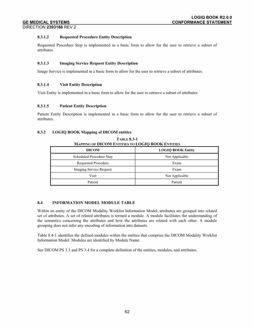
LOGIQ BOOK R2.0.0 GE MEDICAL SYSTEMS CONFORMANCE STATEMENT DIRECTION 2393188 REV 2
62
8.3.1.2 Requested Procedure Entity Description
Requested Procedure Step is implemented in a basic form to allow for the user to retrieve a subset of attributes.
8.3.1.3 Imaging Service Request Entity Description
Image Service is implemented in a basic form to allow for the user to retrieve a subset of attributes.
8.3.1.4 Visit Entity Description
Visit Entity is implemented in a basic form to allow for the user to retrieve a subset of attributes.
8.3.1.5 Patient Entity Description
Patient Entity Description is implemented in a basic form to allow for the user to retrieve a subset of attributes.
8.3.2 LOGIQ BOOK Mapping of DICOM entities
TABLE 8.3-1 MAPPING OF DICOM ENTITIES TO LOGIQ BOOK ENTITIES
DICOM LOGIQ BOOK Entity
Scheduled Procedure Step Not Applicable
Requested Procedure Exam
Imaging Service Request Exam
Visit Not Applicable
Patient Patient
8.4 INFORMATION MODEL MODULE TABLE
Within an entity of the DICOM Modality Worklist Information Model, attributes are grouped into related set of attributes. A set of related attributes is termed a module. A module facilitates the understanding of the semantics concerning the attributes and how the attributes are related with each other. A module grouping does not infer any encoding of information into datasets.
Table 8.4-1 identifies the defined modules within the entities that comprise the DICOM Modality Worklist Information Model. Modules are identified by Module Name.
See DICOM PS 3.3 and PS 3.4 for a complete definition of the entities, modules, and attributes.
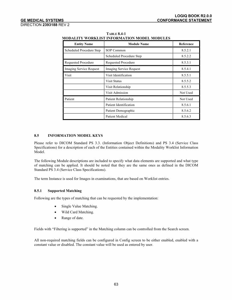
LOGIQ BOOK R2.0.0 GE MEDICAL SYSTEMS CONFORMANCE STATEMENT DIRECTION 2393188 REV 2
63
TABLE 8.4-1 MODALITY WORKLIST INFORMATION MODEL MODULES
Entity Name Module Name Reference
Scheduled Procedure Step SOP Common 8.5.2.1
Scheduled Procedure Step 8.5.2.2
Requested Procedure Requested Procedure 8.5.3.1
Imaging Service Request Imaging Service Request 8.5.4.1
Visit Visit Identification 8.5.5.1
Visit Status 8.5.5.2
Visit Relationship 8.5.5.3
Visit Admission Not Used
Patient Patient Relationship Not Used
Patient Identification 8.5.6.1
Patient Demographic 8.5.6.2
Patient Medical 8.5.6.3
8.5 INFORMATION MODEL KEYS
Please refer to DICOM Standard PS 3.3. (Information Object Definitions) and PS 3.4 (Service Class Specifications) for a description of each of the Entities contained within the Modality Worklist Information Model.
The following Module descriptions are included to specify what data elements are supported and what type of matching can be applied. It should be noted that they are the same ones as defined in the DICOM Standard PS 3.4 (Service Class Specifications).
The term Instance is used for Images in examinations, that are based on Worklist entries.
8.5.1 Supported Matching
Following are the types of matching that can be requested by the implementation:
• Single Value Matching. • Wild Card Matching. • Range of date.
Fields with “Filtering is supported” in the Matching column can be controlled from the Search screen. All non-required matching fields can be configured in Config screen to be either enabled, enabled with a constant value or disabled. The constant value will be used as entered by user.
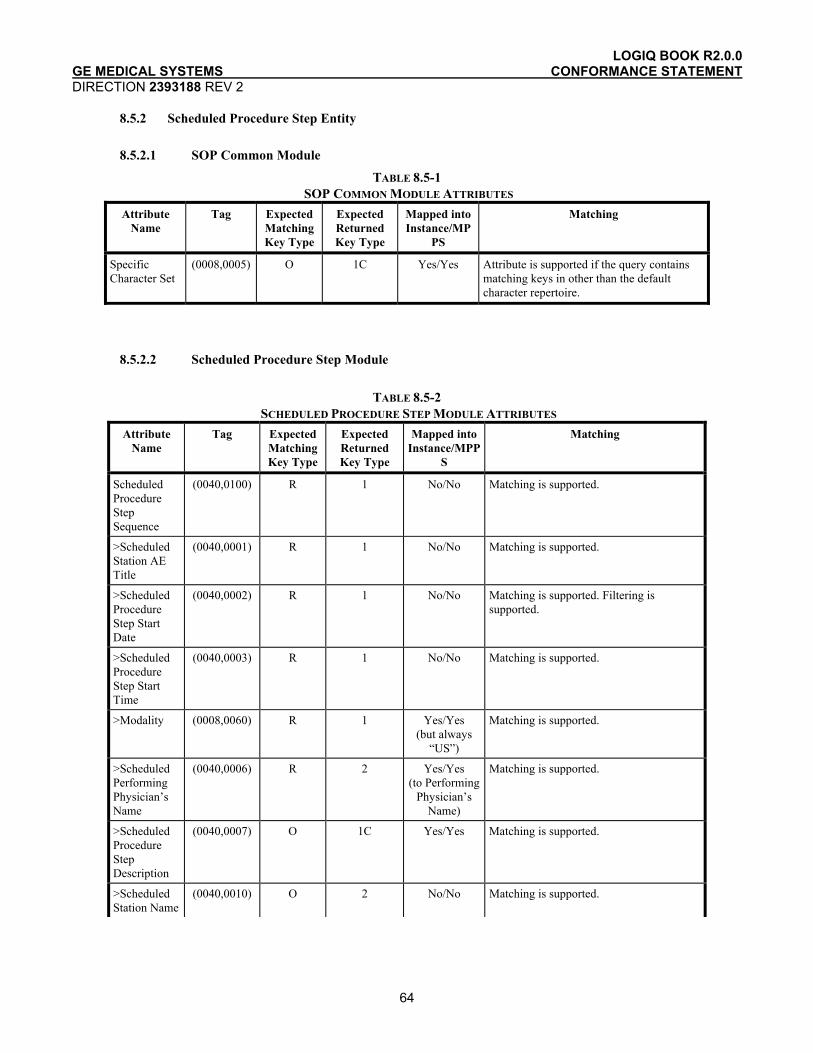
LOGIQ BOOK R2.0.0 GE MEDICAL SYSTEMS CONFORMANCE STATEMENT DIRECTION 2393188 REV 2
64
8.5.2 Scheduled Procedure Step Entity
8.5.2.1 SOP Common Module
TABLE 8.5-1 SOP COMMON MODULE ATTRIBUTES
Attribute Name
Tag Expected Matching Key Type
Expected Returned Key Type
Mapped into Instance/MP
PS
Matching
Specific Character Set
(0008,0005) O 1C Yes/Yes
Attribute is supported if the query contains matching keys in other than the default character repertoire.
8.5.2.2 Scheduled Procedure Step Module
TABLE 8.5-2
SCHEDULED PROCEDURE STEP MODULE ATTRIBUTES Attribute
Name Tag Expected
Matching Key Type
Expected Returned Key Type
Mapped into Instance/MPP
S
Matching
Scheduled Procedure Step Sequence
(0040,0100) R 1 No/No Matching is supported.
>Scheduled Station AE Title
(0040,0001) R 1 No/No Matching is supported.
>Scheduled Procedure Step Start Date
(0040,0002) R 1 No/No Matching is supported. Filtering is supported.
>Scheduled Procedure Step Start Time
(0040,0003) R 1 No/No Matching is supported.
>Modality (0008,0060) R 1 Yes/Yes (but always
“US”)
Matching is supported.
>Scheduled Performing Physician’s Name
(0040,0006) R 2 Yes/Yes (to Performing
Physician’s Name)
Matching is supported.
>Scheduled Procedure Step Description
(0040,0007) O 1C Yes/Yes Matching is supported.
>Scheduled Station Name
(0040,0010) O 2 No/No Matching is supported.
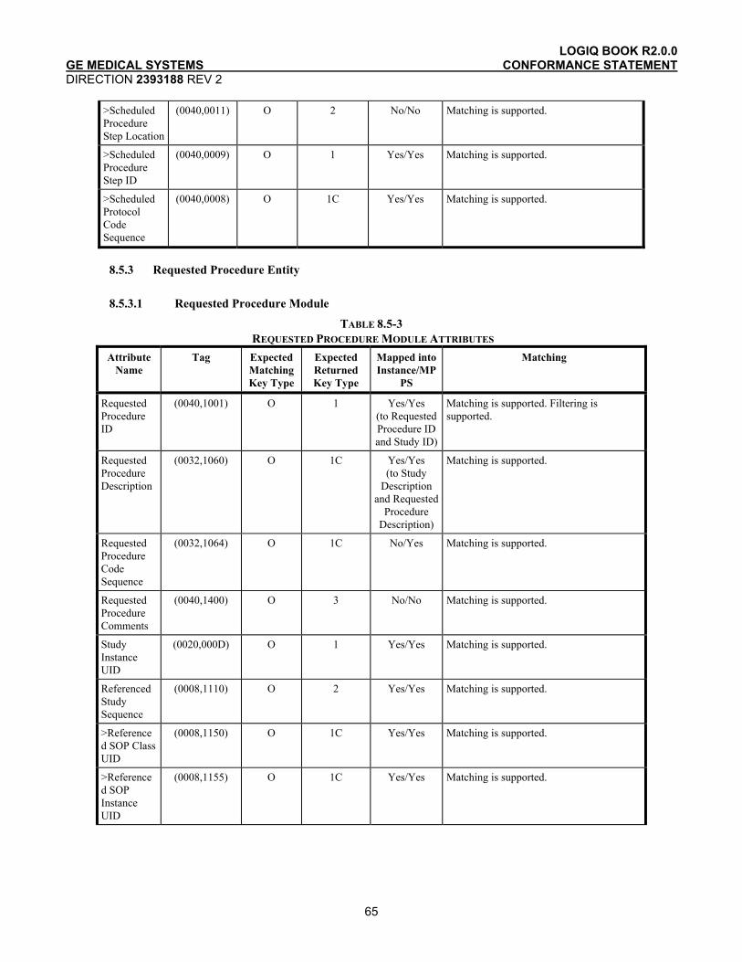
LOGIQ BOOK R2.0.0 GE MEDICAL SYSTEMS CONFORMANCE STATEMENT DIRECTION 2393188 REV 2
65
>Scheduled Procedure Step Location
(0040,0011) O 2 No/No Matching is supported.
>Scheduled Procedure Step ID
(0040,0009) O 1 Yes/Yes Matching is supported.
>Scheduled Protocol Code Sequence
(0040,0008) O 1C Yes/Yes Matching is supported.
8.5.3 Requested Procedure Entity
8.5.3.1 Requested Procedure Module
TABLE 8.5-3 REQUESTED PROCEDURE MODULE ATTRIBUTES
Attribute Name
Tag Expected Matching Key Type
Expected Returned Key Type
Mapped into Instance/MP
PS
Matching
Requested Procedure ID
(0040,1001) O 1 Yes/Yes (to Requested Procedure ID and Study ID)
Matching is supported. Filtering is supported.
Requested Procedure Description
(0032,1060) O 1C Yes/Yes (to Study
Description and Requested
Procedure Description)
Matching is supported.
Requested Procedure Code Sequence
(0032,1064) O 1C No/Yes Matching is supported.
Requested Procedure Comments
(0040,1400) O 3 No/No Matching is supported.
Study Instance UID
(0020,000D) O 1 Yes/Yes
Matching is supported.
Referenced Study Sequence
(0008,1110) O 2 Yes/Yes
Matching is supported.
>Referenced SOP Class UID
(0008,1150) O 1C Yes/Yes
Matching is supported.
>Referenced SOP Instance UID
(0008,1155) O 1C Yes/Yes
Matching is supported.
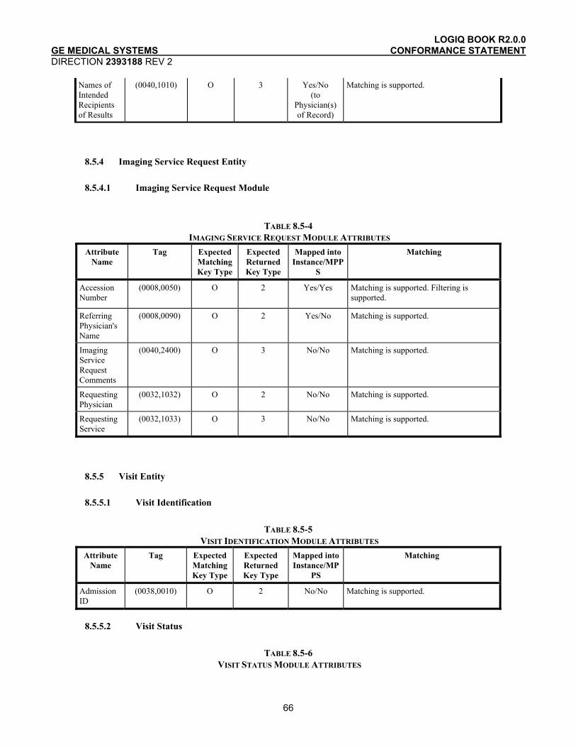
LOGIQ BOOK R2.0.0 GE MEDICAL SYSTEMS CONFORMANCE STATEMENT DIRECTION 2393188 REV 2
66
Names of Intended Recipients of Results
(0040,1010) O 3 Yes/No (to
Physician(s) of Record)
Matching is supported.
8.5.4 Imaging Service Request Entity
8.5.4.1 Imaging Service Request Module
TABLE 8.5-4 IMAGING SERVICE REQUEST MODULE ATTRIBUTES
Attribute Name
Tag Expected Matching Key Type
Expected Returned Key Type
Mapped into Instance/MPP
S
Matching
Accession Number
(0008,0050) O 2 Yes/Yes
Matching is supported. Filtering is supported.
Referring Physician's Name
(0008,0090) O 2 Yes/No Matching is supported.
Imaging Service Request Comments
(0040,2400) O 3 No/No Matching is supported.
Requesting Physician
(0032,1032) O 2 No/No Matching is supported.
Requesting Service
(0032,1033) O 3 No/No Matching is supported.
8.5.5 Visit Entity
8.5.5.1 Visit Identification
TABLE 8.5-5
VISIT IDENTIFICATION MODULE ATTRIBUTES Attribute
Name Tag Expected
Matching Key Type
Expected Returned Key Type
Mapped into Instance/MP
PS
Matching
Admission ID
(0038,0010) O 2 No/No Matching is supported.
8.5.5.2 Visit Status
TABLE 8.5-6
VISIT STATUS MODULE ATTRIBUTES

LOGIQ BOOK R2.0.0 GE MEDICAL SYSTEMS CONFORMANCE STATEMENT DIRECTION 2393188 REV 2
67
Attribute Name
Tag Expected Matching Key Type
Expected Returned Key Type
Mapped into Instance/MP
PS
Matching
Current Patient Location
(0038,0300) O 2 No/No Matching is supported.
8.5.5.3 Visit Relationship
TABLE 8.5-7 VISIT RELATIONSHIP MODULE ATTRIBUTES
Attribute Name
Tag Expected Matching Key Type
Expected Returned Key Type
Mapped into Instance/MPP
S
Matching
Referenced Patient Sequence
(0008,1120) O 2 Yes/Yes
Matching is supported.
>Referenced SOP Class UID
(0008,1150) O 2 Yes/Yes
Matching is supported.
>Referenced SOP Instance UID
(0008,1155) O 2 Yes/Yes
Matching is supported.
8.5.6 Patient Entity
8.5.6.1 Patient Identification
TABLE 8.5-8 PATIENT IDENTIFICATION MODULE ATTRIBUTES
Attribute Name
Tag Expected Matching Key Type
Expected Returned Key Type
Mapped into Instance/MP
PS
Matching
Patient's Name
(0010,0010) R 1 Yes/Yes
Matching is supported. Filtering is supported.
Patient ID (0010,0020) R 1 Yes/Yes
Matching is supported. Filtering is supported.
Other Patient Ids
(0010,1000) O 3 Yes/No Matching is supported.
8.5.6.2 Patient Demographic
TABLE 8.5-9 PATIENT DEMOGRAPHIC MODULE ATTRIBUTES
Attribute Name
Tag Expected Matching Key Type
Expected Returned Key Type
Mapped into Instance/MP
PS
Matching
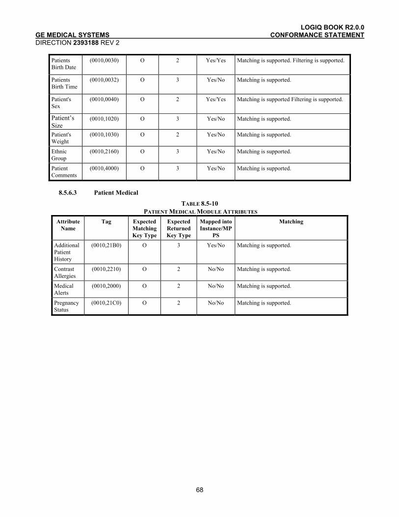
LOGIQ BOOK R2.0.0 GE MEDICAL SYSTEMS CONFORMANCE STATEMENT DIRECTION 2393188 REV 2
68
Patients Birth Date
(0010,0030) O 2 Yes/Yes
Matching is supported. Filtering is supported.
Patients Birth Time
(0010,0032) O 3 Yes/No
Matching is supported.
Patient's Sex
(0010,0040) O 2 Yes/Yes
Matching is supported Filtering is supported.
Patient’s Size
(0010,1020) O 3 Yes/No Matching is supported.
Patient's Weight
(0010,1030) O 2 Yes/No Matching is supported.
Ethnic Group
(0010,2160) O 3 Yes/No Matching is supported.
Patient Comments
(0010,4000) O 3 Yes/No Matching is supported.
8.5.6.3 Patient Medical
TABLE 8.5-10 PATIENT MEDICAL MODULE ATTRIBUTES
Attribute Name
Tag Expected Matching Key Type
Expected Returned Key Type
Mapped into Instance/MP
PS
Matching
Additional Patient History
(0010,21B0) O 3 Yes/No Matching is supported.
Contrast Allergies
(0010,2210) O 2 No/No Matching is supported.
Medical Alerts
(0010,2000) O 2 No/No Matching is supported.
Pregnancy Status
(0010,21C0) O 2 No/No Matching is supported.
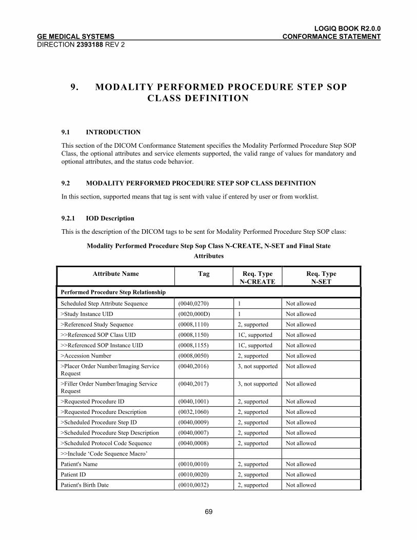
LOGIQ BOOK R2.0.0 GE MEDICAL SYSTEMS CONFORMANCE STATEMENT DIRECTION 2393188 REV 2
69
9. MODALITY PERFORMED PROCEDURE STEP SOP CLASS DEFINITION
9.1 INTRODUCTION
This section of the DICOM Conformance Statement specifies the Modality Performed Procedure Step SOP Class, the optional attributes and service elements supported, the valid range of values for mandatory and optional attributes, and the status code behavior.
9.2 MODALITY PERFORMED PROCEDURE STEP SOP CLASS DEFINITION
In this section, supported means that tag is sent with value if entered by user or from worklist.
9.2.1 IOD Description
This is the description of the DICOM tags to be sent for Modality Performed Procedure Step SOP class:
Modality Performed Procedure Step Sop Class N-CREATE, N-SET and Final State Attributes
Attribute Name Tag Req. Type N-CREATE
Req. Type N-SET
Performed Procedure Step Relationship
Scheduled Step Attribute Sequence (0040,0270) 1 Not allowed
>Study Instance UID (0020,000D) 1 Not allowed
>Referenced Study Sequence (0008,1110) 2, supported Not allowed
>>Referenced SOP Class UID (0008,1150) 1C, supported Not allowed
>>Referenced SOP Instance UID (0008,1155) 1C, supported Not allowed
>Accession Number (0008,0050) 2, supported Not allowed
>Placer Order Number/Imaging Service Request
(0040,2016) 3, not supported Not allowed
>Filler Order Number/Imaging Service Request
(0040,2017) 3, not supported Not allowed
>Requested Procedure ID (0040,1001) 2, supported Not allowed
>Requested Procedure Description (0032,1060) 2, supported Not allowed
>Scheduled Procedure Step ID (0040,0009) 2, supported Not allowed
>Scheduled Procedure Step Description (0040,0007) 2, supported Not allowed
>Scheduled Protocol Code Sequence (0040,0008) 2, supported Not allowed
>>Include ‘Code Sequence Macro’
Patient's Name (0010,0010) 2, supported Not allowed
Patient ID (0010,0020) 2, supported Not allowed
Patient's Birth Date (0010,0032) 2, supported Not allowed

LOGIQ BOOK R2.0.0 GE MEDICAL SYSTEMS CONFORMANCE STATEMENT DIRECTION 2393188 REV 2
70
Attribute Name Tag Req. Type N-CREATE
Req. Type N-SET
Patient's Sex (0010,0040) 2, supported Not allowed
>Referenced Patient Sequence (0008,1120) 2, supported Not allowed
>>Referenced SOP Class UID (0008,1150) 1C, supported Not allowed
>>Referenced SOP Instance UID (0008,1155) 1C, supported Not allowed
Performed Procedure Step Information
Performed Procedure Step ID (0040,0253) 1 Not allowed
Performed Station AE Title (0040,0241) 1 Not allowed
Performed Station Name (0040,0242) 2, supported Not allowed
Performed Location (0040,0243) 2, supported (Institution Name, truncated if necessary to 16 characters)
Not allowed
Performed Procedure Step Start Date (0040,0244) 1 Not allowed
Performed Procedure Step Start Time (0040,0245) 1 Not allowed
Performed Procedure Step Status (0040,0252) 1 3, supported
Performed Procedure Step Description (0040,0254) 2, supported 3, supported
Performed Procedure Type Description (0040,0255) 2, always empty
3, always empty
Procedure Code Sequence (0008,1032) 2, supported 3, supported
>Include ‘Code Sequence Macro’
Performed Procedure Step End Date (0040,0250) 2, always empty
3, supported
Performed Procedure Step End Time (0040,0251) 2, always empty
3, supported
Image Acquisition Results
Modality (0008,0060) 1 Not allowed
Study ID (0020,0010) 2, supported Not allowed
Performed Protocol Code Sequence (0040,0260) 2, supported 3, supported
>Include ‘Code Sequence Macro’
Performed Series Sequence (0040,0340) 2, always empty
3, supported
>Performing Physician's Name (0008,1050) 2C (Required if Sequence Item is present)
2C (Required if Sequence Item is present)
>Protocol Name (0018,1030) 1C (Required if Sequence Item is present)
1C (Required if Sequence Item is present)

LOGIQ BOOK R2.0.0 GE MEDICAL SYSTEMS CONFORMANCE STATEMENT DIRECTION 2393188 REV 2
71
Attribute Name Tag Req. Type N-CREATE
Req. Type N-SET
>Operator's Name (0008,1070) 2C (Required if Sequence Item is present)
2C (Required if Sequence Item is present)
>Series Instance UID (0020,000E) 1C (Required if Sequence Item is present)
1C (Required if Sequence Item is present)
>Series Description (0008,103E) 2C (Required if Sequence Item is present)
2C (Required if Sequence Item is present)
>Retrieve AE Title (0008,0054) 2C (Required if Sequence Item is present)
2C (Required if Sequence Item is present)
>Referenced Image Sequence (0008,1140) 2C (Required if Sequence Item is present)
2C (Required if Sequence Item is present)
>>Referenced SOP Class UID (0008,1150) 1C (Required if Sequence Item is present)
1C (Required if Sequence Item is present)
>>Referenced SOP Instance UID (0008,1155) 1C (Required if Sequence Item is present)
1C (Required if Sequence Item is present)
>Referenced Non-Image Composite SOP Instance Sequence
(0040,0220) 2C (Required if Sequence Item is present)
2C (Required if Sequence Item is present)
>>Referenced SOP Class UID (0008,1150) 1C (Required if Sequence Item is present)
1C (Required if Sequence Item is present)
>>Referenced SOP Instance UID (0008,1155) 1C (Required if Sequence Item is present)
1C (Required if Sequence Item is present)
>Referenced Frame Number (0008,1160) 3, not supported 3, not supported
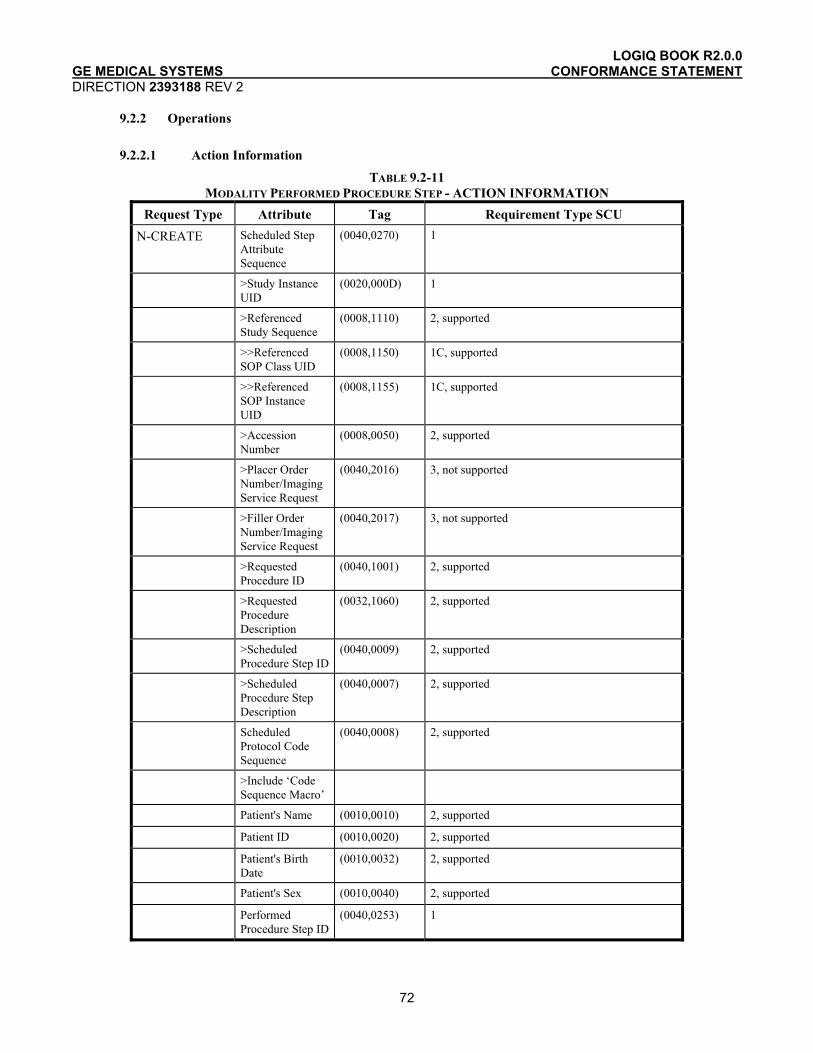
LOGIQ BOOK R2.0.0 GE MEDICAL SYSTEMS CONFORMANCE STATEMENT DIRECTION 2393188 REV 2
72
9.2.2 Operations
9.2.2.1 Action Information
TABLE 9.2-11 MODALITY PERFORMED PROCEDURE STEP - ACTION INFORMATION
Request Type Attribute Tag Requirement Type SCU N-CREATE Scheduled Step
Attribute Sequence
(0040,0270) 1
>Study Instance UID
(0020,000D) 1
>Referenced Study Sequence
(0008,1110) 2, supported
>>Referenced SOP Class UID
(0008,1150) 1C, supported
>>Referenced SOP Instance UID
(0008,1155) 1C, supported
>Accession Number
(0008,0050) 2, supported
>Placer Order Number/Imaging Service Request
(0040,2016) 3, not supported
>Filler Order Number/Imaging Service Request
(0040,2017) 3, not supported
>Requested Procedure ID
(0040,1001) 2, supported
>Requested Procedure Description
(0032,1060) 2, supported
>Scheduled Procedure Step ID
(0040,0009) 2, supported
>Scheduled Procedure Step Description
(0040,0007) 2, supported
Scheduled Protocol Code Sequence
(0040,0008) 2, supported
>Include ‘Code Sequence Macro’
Patient's Name (0010,0010) 2, supported
Patient ID (0010,0020) 2, supported
Patient's Birth Date
(0010,0032) 2, supported
Patient's Sex (0010,0040) 2, supported
Performed Procedure Step ID
(0040,0253) 1
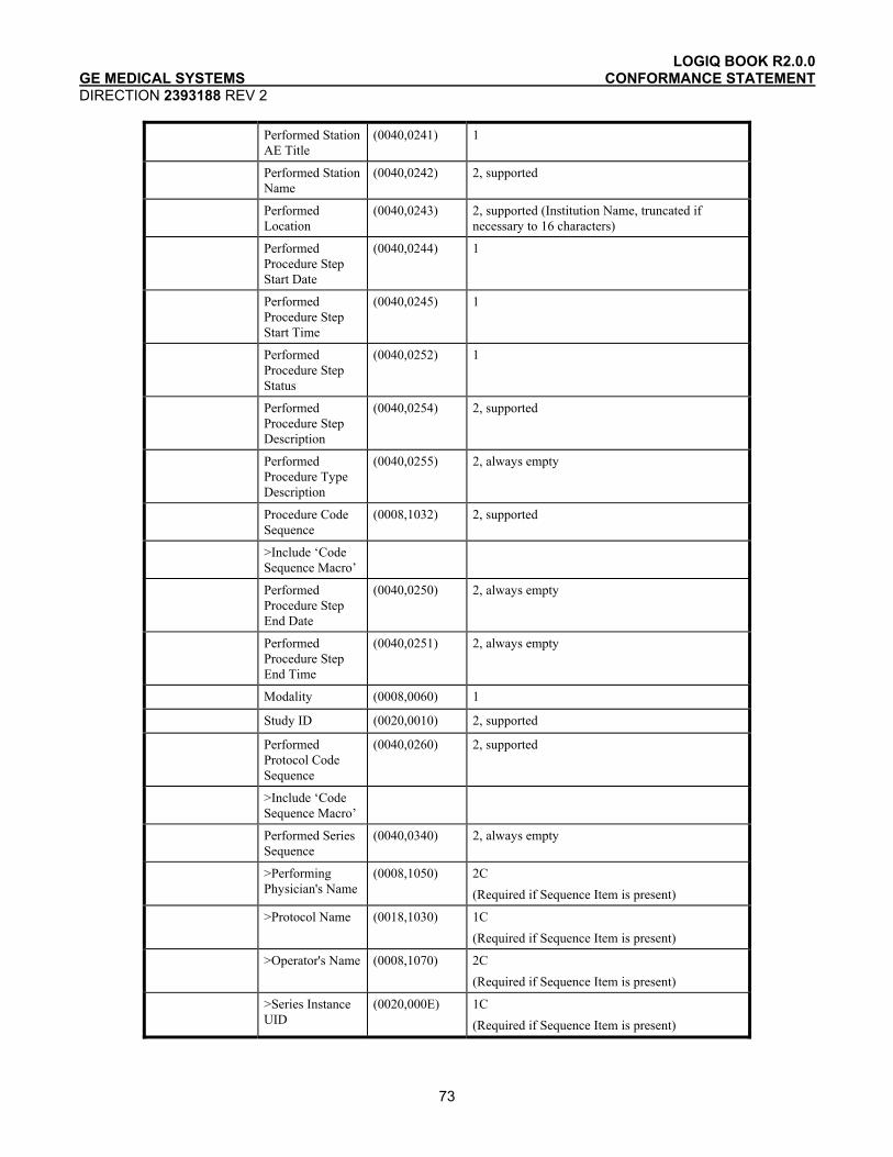
LOGIQ BOOK R2.0.0 GE MEDICAL SYSTEMS CONFORMANCE STATEMENT DIRECTION 2393188 REV 2
73
Performed Station AE Title
(0040,0241) 1
Performed Station Name
(0040,0242) 2, supported
Performed Location
(0040,0243) 2, supported (Institution Name, truncated if necessary to 16 characters)
Performed Procedure Step Start Date
(0040,0244) 1
Performed Procedure Step Start Time
(0040,0245) 1
Performed Procedure Step Status
(0040,0252) 1
Performed Procedure Step Description
(0040,0254) 2, supported
Performed Procedure Type Description
(0040,0255) 2, always empty
Procedure Code Sequence
(0008,1032) 2, supported
>Include ‘Code Sequence Macro’
Performed Procedure Step End Date
(0040,0250) 2, always empty
Performed Procedure Step End Time
(0040,0251) 2, always empty
Modality (0008,0060) 1
Study ID (0020,0010) 2, supported
Performed Protocol Code Sequence
(0040,0260) 2, supported
>Include ‘Code Sequence Macro’
Performed Series Sequence
(0040,0340) 2, always empty
>Performing Physician's Name
(0008,1050) 2C (Required if Sequence Item is present)
>Protocol Name (0018,1030) 1C (Required if Sequence Item is present)
>Operator's Name (0008,1070) 2C (Required if Sequence Item is present)
>Series Instance UID
(0020,000E) 1C (Required if Sequence Item is present)
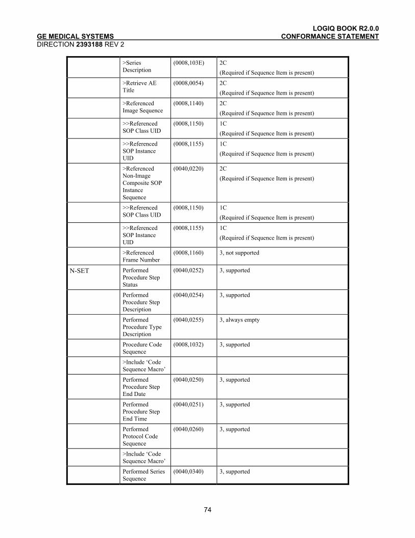
LOGIQ BOOK R2.0.0 GE MEDICAL SYSTEMS CONFORMANCE STATEMENT DIRECTION 2393188 REV 2
74
>Series Description
(0008,103E) 2C (Required if Sequence Item is present)
>Retrieve AE Title
(0008,0054) 2C (Required if Sequence Item is present)
>Referenced Image Sequence
(0008,1140) 2C (Required if Sequence Item is present)
>>Referenced SOP Class UID
(0008,1150) 1C (Required if Sequence Item is present)
>>Referenced SOP Instance UID
(0008,1155) 1C (Required if Sequence Item is present)
>Referenced Non-Image Composite SOP Instance Sequence
(0040,0220) 2C (Required if Sequence Item is present)
>>Referenced SOP Class UID
(0008,1150) 1C (Required if Sequence Item is present)
>>Referenced SOP Instance UID
(0008,1155) 1C (Required if Sequence Item is present)
>Referenced Frame Number
(0008,1160) 3, not supported
N-SET Performed Procedure Step Status
(0040,0252) 3, supported
Performed Procedure Step Description
(0040,0254) 3, supported
Performed Procedure Type Description
(0040,0255) 3, always empty
Procedure Code Sequence
(0008,1032) 3, supported
>Include ‘Code Sequence Macro’
Performed Procedure Step End Date
(0040,0250) 3, supported
Performed Procedure Step End Time
(0040,0251) 3, supported
Performed Protocol Code Sequence
(0040,0260) 3, supported
>Include ‘Code Sequence Macro’
Performed Series Sequence
(0040,0340) 3, supported
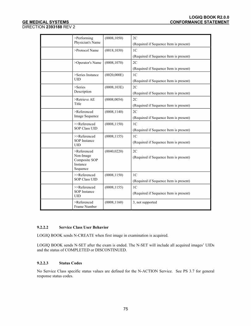
LOGIQ BOOK R2.0.0 GE MEDICAL SYSTEMS CONFORMANCE STATEMENT DIRECTION 2393188 REV 2
75
>Performing Physician's Name
(0008,1050) 2C (Required if Sequence Item is present)
>Protocol Name (0018,1030) 1C (Required if Sequence Item is present)
>Operator's Name (0008,1070) 2C (Required if Sequence Item is present)
>Series Instance UID
(0020,000E) 1C (Required if Sequence Item is present)
>Series Description
(0008,103E) 2C (Required if Sequence Item is present)
>Retrieve AE Title
(0008,0054) 2C (Required if Sequence Item is present)
>Referenced Image Sequence
(0008,1140) 2C (Required if Sequence Item is present)
>>Referenced SOP Class UID
(0008,1150) 1C (Required if Sequence Item is present)
>>Referenced SOP Instance UID
(0008,1155) 1C (Required if Sequence Item is present)
>Referenced Non-Image Composite SOP Instance Sequence
(0040,0220) 2C (Required if Sequence Item is present)
>>Referenced SOP Class UID
(0008,1150) 1C (Required if Sequence Item is present)
>>Referenced SOP Instance UID
(0008,1155) 1C (Required if Sequence Item is present)
>Referenced Frame Number
(0008,1160) 3, not supported
9.2.2.2 Service Class User Behavior
LOGIQ BOOK sends N-CREATE when first image in examination is acquired.
LOGIQ BOOK sends N-SET after the exam is ended. The N-SET will include all acquired images’ UIDs and the status of COMPLETED or DISCONTINUED.
9.2.2.3 Status Codes
No Service Class specific status values are defined for the N-ACTION Service. See PS 3.7 for general response status codes.
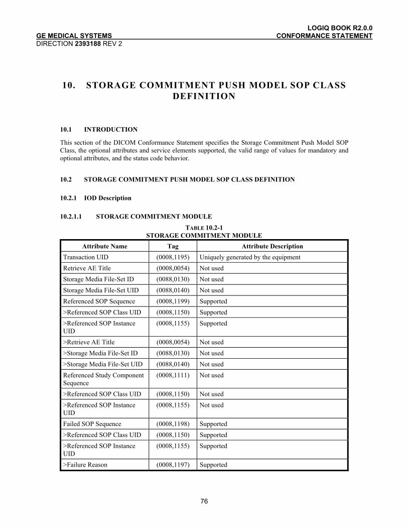
LOGIQ BOOK R2.0.0 GE MEDICAL SYSTEMS CONFORMANCE STATEMENT DIRECTION 2393188 REV 2
76
10. STORAGE COMMITMENT PUSH MODEL SOP CLASS DEFINITION
10.1 INTRODUCTION
This section of the DICOM Conformance Statement specifies the Storage Commitment Push Model SOP Class, the optional attributes and service elements supported, the valid range of values for mandatory and optional attributes, and the status code behavior.
10.2 STORAGE COMMITMENT PUSH MODEL SOP CLASS DEFINITION
10.2.1 IOD Description
10.2.1.1 STORAGE COMMITMENT MODULE
TABLE 10.2-1 STORAGE COMMITMENT MODULE
Attribute Name Tag Attribute Description Transaction UID (0008,1195) Uniquely generated by the equipment
Retrieve AE Title (0008,0054) Not used
Storage Media File-Set ID (0088,0130) Not used
Storage Media File-Set UID (0088,0140) Not used
Referenced SOP Sequence (0008,1199) Supported
>Referenced SOP Class UID (0008,1150) Supported
>Referenced SOP Instance UID
(0008,1155) Supported
>Retrieve AE Title (0008,0054) Not used
>Storage Media File-Set ID (0088,0130) Not used
>Storage Media File-Set UID (0088,0140) Not used
Referenced Study Component Sequence
(0008,1111) Not used
>Referenced SOP Class UID (0008,1150) Not used
>Referenced SOP Instance UID
(0008,1155) Not used
Failed SOP Sequence (0008,1198) Supported
>Referenced SOP Class UID (0008,1150) Supported
>Referenced SOP Instance UID
(0008,1155) Supported
>Failure Reason (0008,1197) Supported
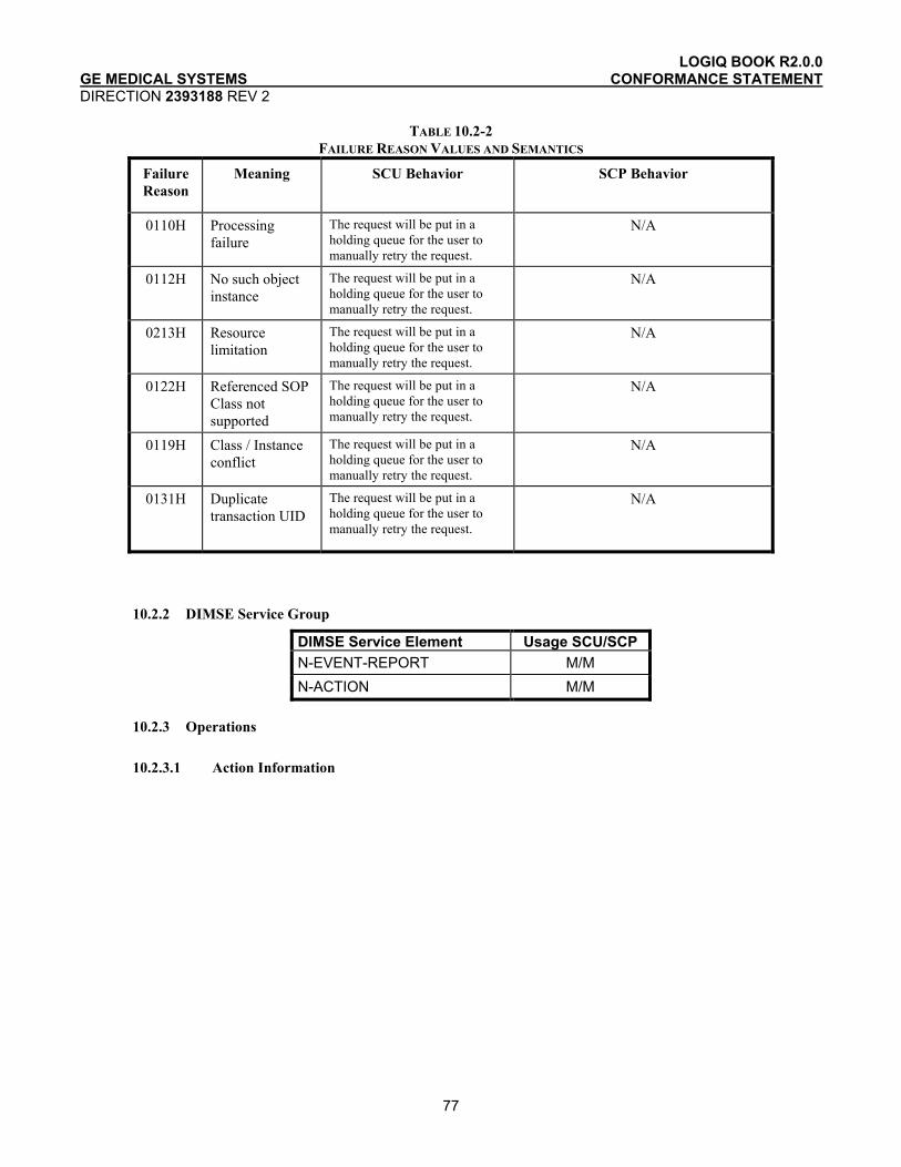
LOGIQ BOOK R2.0.0 GE MEDICAL SYSTEMS CONFORMANCE STATEMENT DIRECTION 2393188 REV 2
77
TABLE 10.2-2 FAILURE REASON VALUES AND SEMANTICS
Failure Reason
Meaning SCU Behavior SCP Behavior
0110H Processing failure
The request will be put in a holding queue for the user to manually retry the request.
N/A
0112H No such object instance
The request will be put in a holding queue for the user to manually retry the request.
N/A
0213H Resource limitation
The request will be put in a holding queue for the user to manually retry the request.
N/A
0122H Referenced SOP Class not supported
The request will be put in a holding queue for the user to manually retry the request.
N/A
0119H Class / Instance conflict
The request will be put in a holding queue for the user to manually retry the request.
N/A
0131H Duplicate transaction UID
The request will be put in a holding queue for the user to manually retry the request.
N/A
10.2.2 DIMSE Service Group
DIMSE Service Element Usage SCU/SCP N-EVENT-REPORT M/M N-ACTION M/M
10.2.3 Operations
10.2.3.1 Action Information
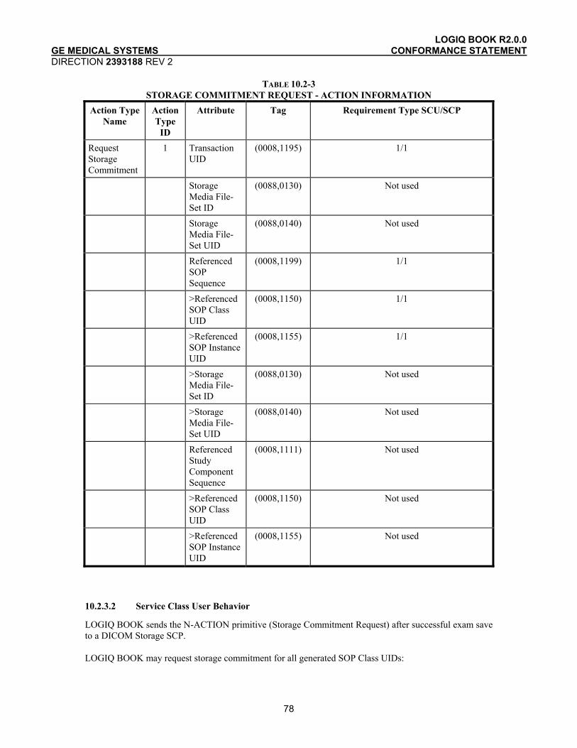
LOGIQ BOOK R2.0.0 GE MEDICAL SYSTEMS CONFORMANCE STATEMENT DIRECTION 2393188 REV 2
78
TABLE 10.2-3 STORAGE COMMITMENT REQUEST - ACTION INFORMATION
Action Type Name
Action Type
ID
Attribute Tag Requirement Type SCU/SCP
Request Storage Commitment
1 Transaction UID
(0008,1195) 1/1
Storage Media File-Set ID
(0088,0130) Not used
Storage Media File-Set UID
(0088,0140) Not used
Referenced SOP Sequence
(0008,1199) 1/1
>Referenced SOP Class UID
(0008,1150) 1/1
>Referenced SOP Instance UID
(0008,1155) 1/1
>Storage Media File-Set ID
(0088,0130) Not used
>Storage Media File-Set UID
(0088,0140) Not used
Referenced Study Component Sequence
(0008,1111) Not used
>Referenced SOP Class UID
(0008,1150) Not used
>Referenced SOP Instance UID
(0008,1155) Not used
10.2.3.2 Service Class User Behavior
LOGIQ BOOK sends the N-ACTION primitive (Storage Commitment Request) after successful exam save to a DICOM Storage SCP.
LOGIQ BOOK may request storage commitment for all generated SOP Class UIDs:

LOGIQ BOOK R2.0.0 GE MEDICAL SYSTEMS CONFORMANCE STATEMENT DIRECTION 2393188 REV 2
79
Ultrasound Multi-frame Image Storage 1.2.840.10008.5.1.4.1.1.3.1
Ultrasound Multi-frame Image Storage (Retired) 1.2.840.10008.5.1.4.1.1.3
Ultrasound Image Storage 1.2.840.10008.5.1.4.1.1.6.1
Ultrasound Image Storage (Retired) 1.2.840.10008.5.1.4.1.1.6
Secondary Capture Image Storage 1.2.840.10008.5.1.4.1.1.7
The association for the N-ACTION is disconnected after processing the response. Thus, the N-EVENT-REPORT must be sent on a separate association.
The Referenced Study Component Sequence Attribute is not supported.
The Transaction UID is valid for two days. If no answer is received, the request will be removed without warning the user.
The optional Storage Media File-Set ID & UID Attributes in the N-ACTION are not supported.
On receipt of an unsuccessful N-ACTION Response Status Code from the SCP, the request will be put in a holding queue for the user to manually retry the request.
10.2.3.3 Status Codes
No Service Class specific status values are defined for the N-ACTION Service. See PS 3.7 for general response status codes.
10.2.4 Notifications
LOGIQ BOOK will only listen for an N-EVENT-REPORT from the SCP in a new association on the listen port for Verification and Storage Commitment.
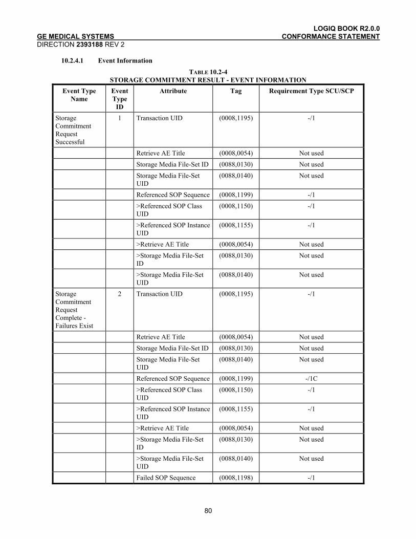
LOGIQ BOOK R2.0.0 GE MEDICAL SYSTEMS CONFORMANCE STATEMENT DIRECTION 2393188 REV 2
80
10.2.4.1 Event Information
TABLE 10.2-4 STORAGE COMMITMENT RESULT - EVENT INFORMATION
Event Type Name
Event Type
ID
Attribute Tag Requirement Type SCU/SCP
Storage Commitment Request Successful
1 Transaction UID (0008,1195) -/1
Retrieve AE Title (0008,0054) Not used
Storage Media File-Set ID (0088,0130) Not used
Storage Media File-Set UID
(0088,0140) Not used
Referenced SOP Sequence (0008,1199) -/1
>Referenced SOP Class UID
(0008,1150) -/1
>Referenced SOP Instance UID
(0008,1155) -/1
>Retrieve AE Title (0008,0054) Not used
>Storage Media File-Set ID
(0088,0130) Not used
>Storage Media File-Set UID
(0088,0140) Not used
Storage Commitment Request Complete - Failures Exist
2 Transaction UID (0008,1195) -/1
Retrieve AE Title (0008,0054) Not used
Storage Media File-Set ID (0088,0130) Not used
Storage Media File-Set UID
(0088,0140) Not used
Referenced SOP Sequence (0008,1199) -/1C
>Referenced SOP Class UID
(0008,1150) -/1
>Referenced SOP Instance UID
(0008,1155) -/1
>Retrieve AE Title (0008,0054) Not used
>Storage Media File-Set ID
(0088,0130) Not used
>Storage Media File-Set UID
(0088,0140) Not used
Failed SOP Sequence (0008,1198) -/1
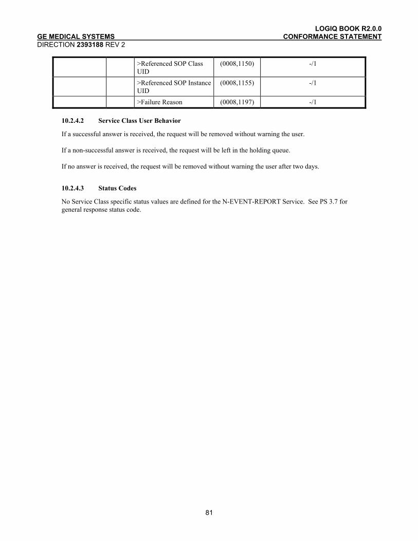
LOGIQ BOOK R2.0.0 GE MEDICAL SYSTEMS CONFORMANCE STATEMENT DIRECTION 2393188 REV 2
81
>Referenced SOP Class UID
(0008,1150) -/1
>Referenced SOP Instance UID
(0008,1155) -/1
>Failure Reason (0008,1197) -/1
10.2.4.2 Service Class User Behavior
If a successful answer is received, the request will be removed without warning the user.
If a non-successful answer is received, the request will be left in the holding queue.
If no answer is received, the request will be removed without warning the user after two days.
10.2.4.3 Status Codes
No Service Class specific status values are defined for the N-EVENT-REPORT Service. See PS 3.7 for general response status code.
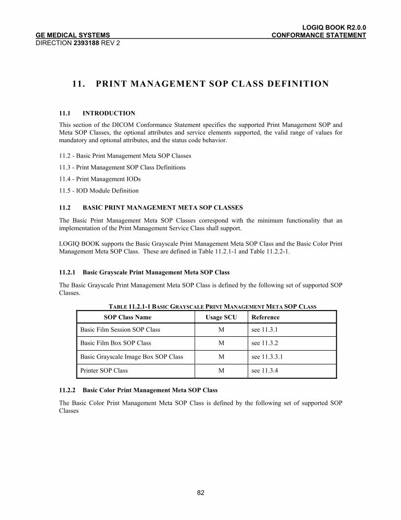
LOGIQ BOOK R2.0.0 GE MEDICAL SYSTEMS CONFORMANCE STATEMENT DIRECTION 2393188 REV 2
82
11. PRINT MANAGEMENT SOP CLASS DEFINITION
11.1 INTRODUCTION
This section of the DICOM Conformance Statement specifies the supported Print Management SOP and Meta SOP Classes, the optional attributes and service elements supported, the valid range of values for mandatory and optional attributes, and the status code behavior.
11.2 - Basic Print Management Meta SOP Classes
11.3 - Print Management SOP Class Definitions
11.4 - Print Management IODs
11.5 - IOD Module Definition
11.2 BASIC PRINT MANAGEMENT META SOP CLASSES
The Basic Print Management Meta SOP Classes correspond with the minimum functionality that an implementation of the Print Management Service Class shall support.
LOGIQ BOOK supports the Basic Grayscale Print Management Meta SOP Class and the Basic Color Print Management Meta SOP Class. These are defined in Table 11.2.1-1 and Table 11.2.2-1.
11.2.1 Basic Grayscale Print Management Meta SOP Class
The Basic Grayscale Print Management Meta SOP Class is defined by the following set of supported SOP Classes.
TABLE 11.2.1-1 BASIC GRAYSCALE PRINT MANAGEMENT META SOP CLASS SOP Class Name Usage SCU Reference
Basic Film Session SOP Class M see 11.3.1
Basic Film Box SOP Class M see 11.3.2
Basic Grayscale Image Box SOP Class M see 11.3.3.1
Printer SOP Class M see 11.3.4
11.2.2 Basic Color Print Management Meta SOP Class
The Basic Color Print Management Meta SOP Class is defined by the following set of supported SOP Classes
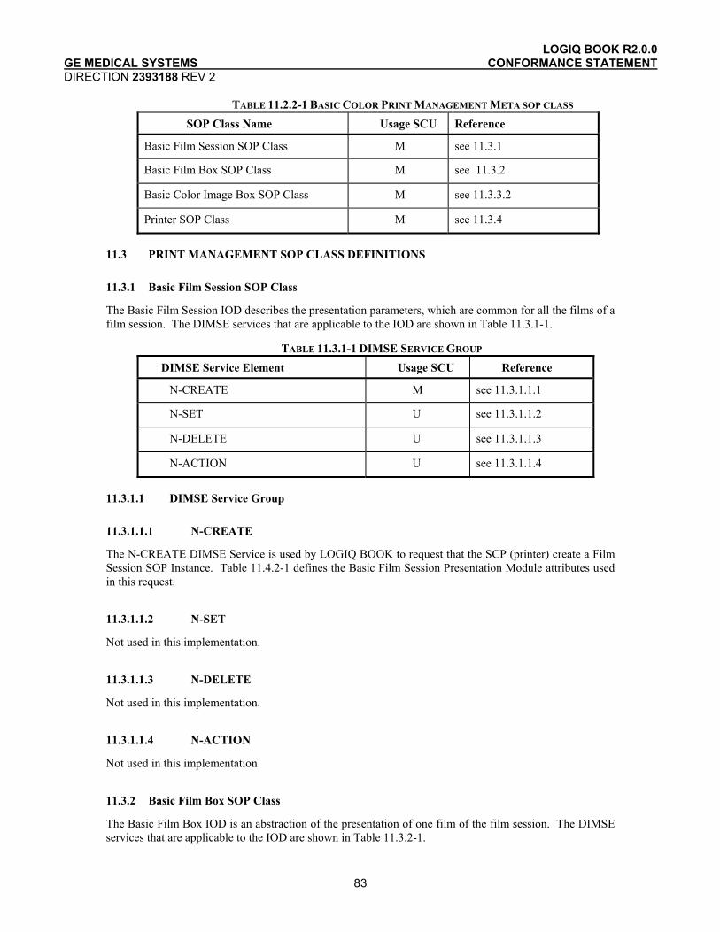
LOGIQ BOOK R2.0.0 GE MEDICAL SYSTEMS CONFORMANCE STATEMENT DIRECTION 2393188 REV 2
83
TABLE 11.2.2-1 BASIC COLOR PRINT MANAGEMENT META SOP CLASS SOP Class Name Usage SCU Reference
Basic Film Session SOP Class M see 11.3.1
Basic Film Box SOP Class M see 11.3.2
Basic Color Image Box SOP Class M see 11.3.3.2
Printer SOP Class M see 11.3.4
11.3 PRINT MANAGEMENT SOP CLASS DEFINITIONS
11.3.1 Basic Film Session SOP Class
The Basic Film Session IOD describes the presentation parameters, which are common for all the films of a film session. The DIMSE services that are applicable to the IOD are shown in Table 11.3.1-1.
TABLE 11.3.1-1 DIMSE SERVICE GROUP DIMSE Service Element Usage SCU Reference
N-CREATE M see 11.3.1.1.1
N-SET U see 11.3.1.1.2
N-DELETE U see 11.3.1.1.3
N-ACTION U see 11.3.1.1.4
11.3.1.1 DIMSE Service Group
11.3.1.1.1 N-CREATE
The N-CREATE DIMSE Service is used by LOGIQ BOOK to request that the SCP (printer) create a Film Session SOP Instance. Table 11.4.2-1 defines the Basic Film Session Presentation Module attributes used in this request.
11.3.1.1.2 N-SET
Not used in this implementation.
11.3.1.1.3 N-DELETE
Not used in this implementation.
11.3.1.1.4 N-ACTION
Not used in this implementation
11.3.2 Basic Film Box SOP Class
The Basic Film Box IOD is an abstraction of the presentation of one film of the film session. The DIMSE services that are applicable to the IOD are shown in Table 11.3.2-1.
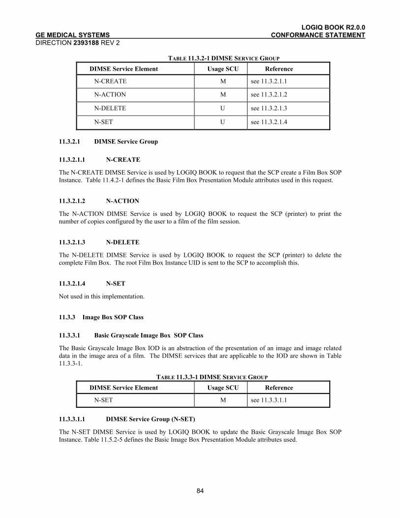
LOGIQ BOOK R2.0.0 GE MEDICAL SYSTEMS CONFORMANCE STATEMENT DIRECTION 2393188 REV 2
84
TABLE 11.3.2-1 DIMSE SERVICE GROUP DIMSE Service Element Usage SCU Reference
N-CREATE M see 11.3.2.1.1
N-ACTION M see 11.3.2.1.2
N-DELETE U see 11.3.2.1.3
N-SET U see 11.3.2.1.4
11.3.2.1 DIMSE Service Group
11.3.2.1.1 N-CREATE
The N-CREATE DIMSE Service is used by LOGIQ BOOK to request that the SCP create a Film Box SOP Instance. Table 11.4.2-1 defines the Basic Film Box Presentation Module attributes used in this request.
11.3.2.1.2 N-ACTION
The N-ACTION DIMSE Service is used by LOGIQ BOOK to request the SCP (printer) to print the number of copies configured by the user to a film of the film session.
11.3.2.1.3 N-DELETE
The N-DELETE DIMSE Service is used by LOGIQ BOOK to request the SCP (printer) to delete the complete Film Box. The root Film Box Instance UID is sent to the SCP to accomplish this.
11.3.2.1.4 N-SET
Not used in this implementation.
11.3.3 Image Box SOP Class
11.3.3.1 Basic Grayscale Image Box SOP Class
The Basic Grayscale Image Box IOD is an abstraction of the presentation of an image and image related data in the image area of a film. The DIMSE services that are applicable to the IOD are shown in Table 11.3.3-1.
TABLE 11.3.3-1 DIMSE SERVICE GROUP DIMSE Service Element Usage SCU Reference
N-SET M see 11.3.3.1.1
11.3.3.1.1 DIMSE Service Group (N-SET)
The N-SET DIMSE Service is used by LOGIQ BOOK to update the Basic Grayscale Image Box SOP Instance. Table 11.5.2-5 defines the Basic Image Box Presentation Module attributes used.

LOGIQ BOOK R2.0.0 GE MEDICAL SYSTEMS CONFORMANCE STATEMENT DIRECTION 2393188 REV 2
85
11.3.3.2 Basic Color Image Box SOP Class
The Basic Color Image Box IOD is an abstraction of the presentation of an image and image related data in the image area of a film. The DIMSE services that are applicable to the IOD are shown in Table 11.3.3-2.
TABLE 11.3.3-2 DIMSE SERVICE GROUP DIMSE Service Element Usage SCU Reference
N-SET M see 11.3.3.2.1
11.3.3.2.1 DIMSE Service Group (N-SET)
The N-SET DIMSE Service is used by LOGIQ BOOK to update the Basic Color Image Box SOP Instance. Table 11.5.2-5 defines the Basic Image Box Presentation Module attributes used.
11.3.4 Printer SOP Class
The Printer IOD is an abstraction of the hard copy printer and is the basic Information Entity to monitor the status of the printer. The DIMSE services that are applicable to the IOD are shown in table 11.3.4-1.
11.3.4.1 DIMSE Service Group
TABLE 11.3.4-1 DIMSE SERVICE GROUP DIMSE Service Element Usage SCU Reference
N-EVENT-REPORT M see 11.3.4.1.1
N-GET U see 11.3.4.1.2
11.3.4.1.1 N-EVENT_REPORT
LOGIQ BOOK confirms the N-EVENT-REPORT initiated by the SCP (printer).
11.3.4.1.2 N-GET
Used by LOGIQ BOOK to request the SCP to get a Printer SOP Instance. Table 11.5.2-6 defines the Printer Module attributes.
11.4 PRINT MANAGEMENT IODS
Within an entity of a DICOM Print Management, attributes are grouped into a related set of attributes. A set of related attributes is termed a module. A module facilitates the understanding of the semantics concerning the attributes and how the attributes are related with each other. A module grouping does not infer any encoding of information into datasets.
Table 11.4.1-1, Table 11.4.2-1, Table 11.4.3-1, and Table 11.4.4-1 identify the defined modules within the entities which comprise the DICOM Print Management Service IODs. Modules are identified by Module Name.
See DICOM for a complete definition of the entities, modules and attributes.

LOGIQ BOOK R2.0.0 GE MEDICAL SYSTEMS CONFORMANCE STATEMENT DIRECTION 2393188 REV 2
86
11.4.1 Film Session IOD Module
TABLE 11.4.1-1 FILM SESSION IOD MODULES Module Name Reference Module Description
SOP Common Module 11.5.2.1 Contains SOP Common information
Basic Film Session Presentation Module
11.5.2.1 Contains Film Session presentation information
Basic Film Session Relationship Module
11.5.2.2 References to related SOPs
11.4.2 Basic Film Box IOD Module Table
TABLE 11.4.2-1 BASIC FILM BOX IOD MODULES Module Name Reference
SOP Common Module 11.5.1.1
Basic Film Box Presentation Module 11.5.2.3
Basic Film Box Relationship Module 11.5.2.2
11.4.3 Basic Image Box IOD Module Table
TABLE 11.4.3-1 BASIC IMAGE BOX IOD MODULES Module Name Reference
SOP Common Module 11.5.1.1
Image Box Pixel Presentation Module 11.5.2.5
11.4.4 Printer IOD Module Table
TABLE 11.4.4-1 PRINTER IOD MODULES Module Name Reference
SOP Common Module 11.5.1.1
Printer Module 11.5.2.6
11.5 INFORMATION MODULE DEFINITIONS
Please refer to DICOM Standard Part 3 (Information Object Definitions) for a description of each of the entities and modules that comprise the Print Management.
The following modules are included to convey Enumerated Values, Defined Terms, and Optional Attributes supported.

LOGIQ BOOK R2.0.0 GE MEDICAL SYSTEMS CONFORMANCE STATEMENT DIRECTION 2393188 REV 2
87
11.5.1 General Modules
11.5.1.1 SOP Common Module
This section defines the attributes that are required for proper functioning and identification of the associated SOP Instances. They do not specify any semantics about the Real-World Object represented by the IOD.
TABLE 11.5.1-1 SOP COMMON MODULE ATTRIBUTES Attribute Name Tag Type Attribute Description
SOP Class UID (0008,0016) 1 Varies with Module Instance and DIMSE Service being used. 1.2.840.100011.5.1.1.1 (Film Session) 1.2.840.100011.5.1.1.2 (Film Box) 1.2.840.100011.5.1.1.4 (Image Box)
SOP Instance UID (0008,0018) 1 Provided by SCP (printer).
Specific Character Set (0008,0005) 1C Not used as expanded or replacement character sets not used.
Instance Creation Date (0008,0012) 3 Not used.
Instance Creation Time (0008,0013) 3 Not used.
Instance Creator UID (0008,0014) 3 Not used.
11.5.2 Print Management Modules
For all user configurable tags with no default, no value will be sent if the tag is not configured.
11.5.2.1 Basic Film Session Presentation Module
This section defines the attributes that are common for all films of a film session. The attributes described in table 11.5.2-1 apply when the N-CREATE DIMSE service is used.

LOGIQ BOOK R2.0.0 GE MEDICAL SYSTEMS CONFORMANCE STATEMENT DIRECTION 2393188 REV 2
88
TABLE 11.5.2-1 BASIC FILM SESSION PRESENTATION MODULE ATTRIBUTES Attribute Name Tag USAGE
(SCU) Attribute Description
Number of Copies (2000,0010) U Defined Terms used (user configurable): Default is 1. Max is 99.
Print Priority (2000,0020) U Defined Terms used (user configurable):
HIGH, MED, LOW. Default is HIGH.
Medium Type (2000,0030) U Defined Terms used (user configurable): PAPER BLUE FILM CLEAR FILM Default is CLEAR FILM.
Film Destination (2000,0040) U Defined Terms used (user configurable): MAGAZINE - default PROCESSOR
Film Session Label (2000,0050) U User configurable. No default.
Memory Allocation (2000,0060) U Not Used
11.5.2.2 Basic Film Session Relationship Module
TABLE 11.5.2-2 BASIC FILM SESSION RELATIONSHIP MODULE ATTRIBUTES Attribute Name Tag USAGE
(SCU) Attribute Description
Referenced Film Box Sequence (2000,0500) U Not used
>Referenced SOP Class UID (0008,1150) U
>Referenced SOP Instance UID (0008,1155) U
11.5.2.3 Basic Film Box Presentation Module
The attributes described in table 11.5.2-3 apply when the N-CREATE DIMSE service is used.
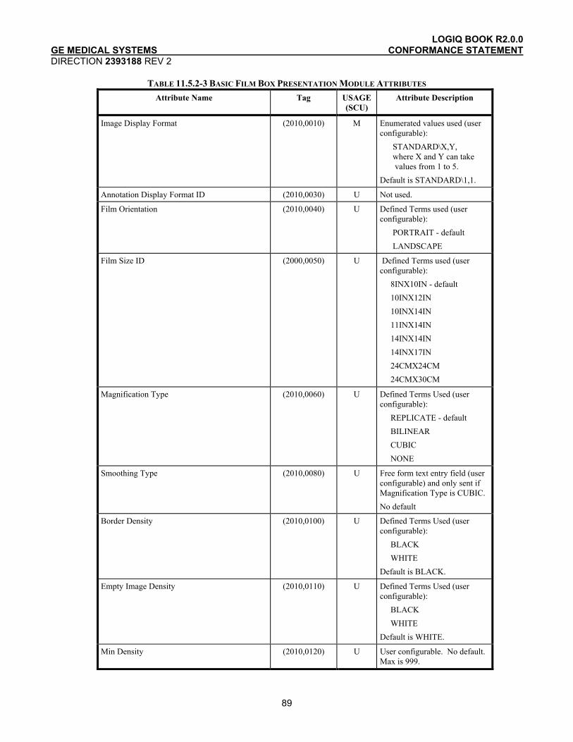
LOGIQ BOOK R2.0.0 GE MEDICAL SYSTEMS CONFORMANCE STATEMENT DIRECTION 2393188 REV 2
89
TABLE 11.5.2-3 BASIC FILM BOX PRESENTATION MODULE ATTRIBUTES Attribute Name Tag USAGE
(SCU) Attribute Description
Image Display Format (2010,0010) M Enumerated values used (user configurable): STANDARD\X,Y, where X and Y can take values from 1 to 5. Default is STANDARD\1,1.
Annotation Display Format ID (2010,0030) U Not used.
Film Orientation (2010,0040) U Defined Terms used (user configurable): PORTRAIT - default LANDSCAPE
Film Size ID (2000,0050) U Defined Terms used (user configurable): 8INX10IN - default 10INX12IN 10INX14IN 11INX14IN 14INX14IN 14INX17IN 24CMX24CM 24CMX30CM
Magnification Type (2010,0060) U Defined Terms Used (user configurable): REPLICATE - default BILINEAR CUBIC NONE
Smoothing Type (2010,0080) U Free form text entry field (user configurable) and only sent if Magnification Type is CUBIC. No default
Border Density (2010,0100) U Defined Terms Used (user configurable): BLACK WHITE Default is BLACK.
Empty Image Density (2010,0110) U Defined Terms Used (user configurable): BLACK WHITE Default is WHITE.
Min Density (2010,0120) U User configurable. No default. Max is 999.
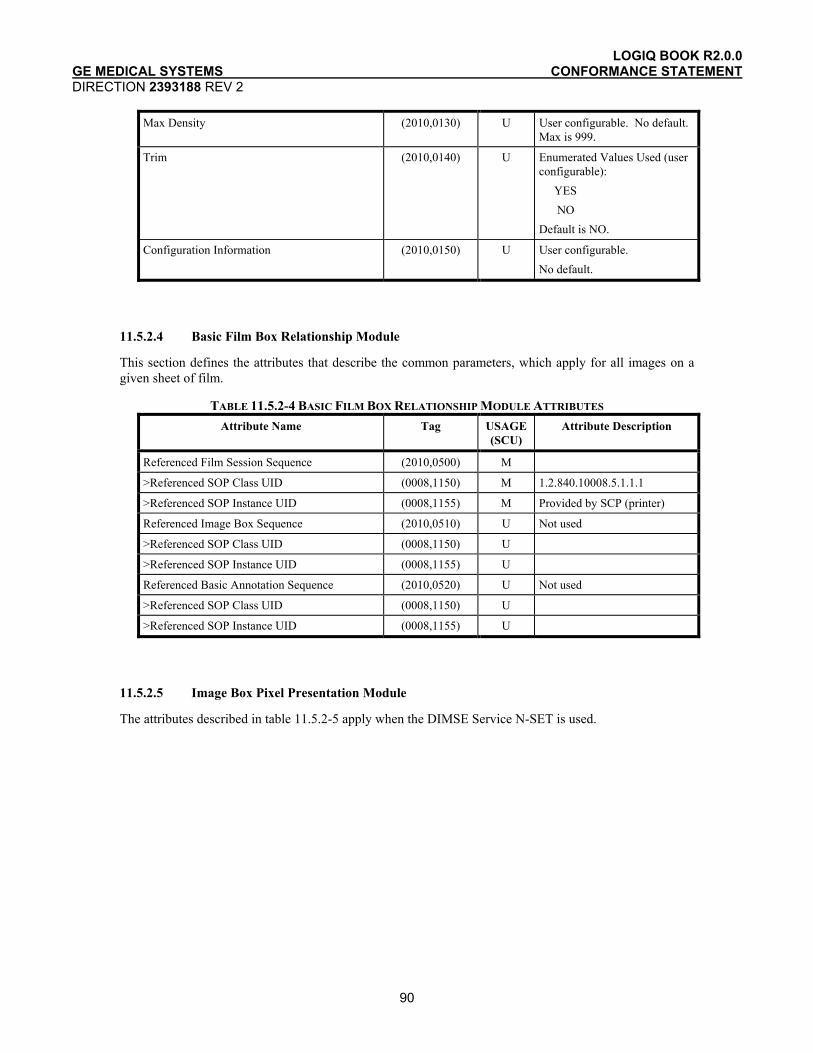
LOGIQ BOOK R2.0.0 GE MEDICAL SYSTEMS CONFORMANCE STATEMENT DIRECTION 2393188 REV 2
90
Max Density (2010,0130) U User configurable. No default. Max is 999.
Trim (2010,0140) U Enumerated Values Used (user configurable): YES NO Default is NO.
Configuration Information (2010,0150) U User configurable. No default.
11.5.2.4 Basic Film Box Relationship Module
This section defines the attributes that describe the common parameters, which apply for all images on a given sheet of film.
TABLE 11.5.2-4 BASIC FILM BOX RELATIONSHIP MODULE ATTRIBUTES Attribute Name Tag USAGE
(SCU) Attribute Description
Referenced Film Session Sequence (2010,0500) M
>Referenced SOP Class UID (0008,1150) M 1.2.840.10008.5.1.1.1
>Referenced SOP Instance UID (0008,1155) M Provided by SCP (printer)
Referenced Image Box Sequence (2010,0510) U Not used
>Referenced SOP Class UID (0008,1150) U
>Referenced SOP Instance UID (0008,1155) U
Referenced Basic Annotation Sequence (2010,0520) U Not used
>Referenced SOP Class UID (0008,1150) U
>Referenced SOP Instance UID (0008,1155) U
11.5.2.5 Image Box Pixel Presentation Module
The attributes described in table 11.5.2-5 apply when the DIMSE Service N-SET is used.

LOGIQ BOOK R2.0.0 GE MEDICAL SYSTEMS CONFORMANCE STATEMENT DIRECTION 2393188 REV 2
91
TABLE 11.5.2-5 IMAGE BOX PIXEL PRESENTATION MODULE ATTRIBUTES Attribute Name Tag USAGE
(SCU) Attribute Description
Image Position (2020,0010) M Based on the image display format.
Polarity (2020,0020) U Defined term, NORMAL
Requested Image Size (2020,0030) U Not sent
Basic Grayscale Image Sequence (2020,0110) M
>Samples Per Pixel (0028,0002) M Value = ‘1’
>Photometric Interpretation (0028,0004) M Defined Term MONOCHROME2 used
>Rows (0028,0010) M Value depends on scanning mode and configuration setup.
>Columns (0028,0011) M Value depends on scanning mode and configuration setup.
>Pixel Aspect Ratio (0028,0034) MC Not used
>Bits Allocated (0028,0100) M Value always = 0008H
>Bits Stored (0028,0101) M Value always = 0008H
>High Bit (0028,0102) M Value always = 0007H
>Pixel Representation (0028,0103) M Defined Value ‘0’ - unsigned integer
>Pixel Data (7FE0,0010) M
Basic Color Image Sequence (2020,0111) M
>Samples Per Pixel (0028,0002) M Value = ‘3’
>Photometric Interpretation (0028,0004) M Defined Term RGB used
>Rows (0028,0010) M Value depends on scanning mode and configuration setup.
>Columns (0028,0011) M Value depends on scanning mode and configuration setup.
>Pixel Aspect Ratio (0028,0034) MC Not used
>Bits Allocated (0028,0100) M Value always = 0008H
>Bits Stored (0028,0101) M Value always = 0008H
>High Bit (0028,0102) M Value always = 0007H
>Pixel Representation (0028,0103) M Defined Value ‘0’ - unsigned integer
>Pixel Data (7FE0,0010) M
Planar Configuration (0028, 0006) M 0001H, color-by-plane, when Basic Color Image Sequence is set
11.5.2.6 Printer Module
This section defines the attributes that are used to monitor the status of the printer. The attributes described in Table 11.5.2-6 apply when the DIMSE Service N-GET is used.
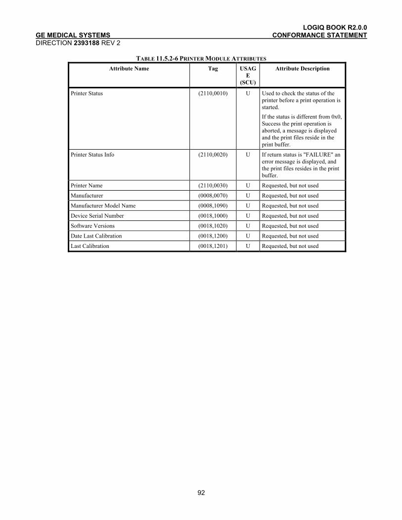
LOGIQ BOOK R2.0.0 GE MEDICAL SYSTEMS CONFORMANCE STATEMENT DIRECTION 2393188 REV 2
92
TABLE 11.5.2-6 PRINTER MODULE ATTRIBUTES Attribute Name Tag USAG
E (SCU)
Attribute Description
Printer Status (2110,0010) U Used to check the status of the printer before a print operation is started. If the status is different from 0x0, Success the print operation is aborted, a message is displayed and the print files reside in the print buffer.
Printer Status Info (2110,0020) U If return status is "FAILURE" an error message is displayed, and the print files resides in the print buffer.
Printer Name (2110,0030) U Requested, but not used
Manufacturer (0008,0070) U Requested, but not used
Manufacturer Model Name (0008,1090) U Requested, but not used
Device Serial Number (0018,1000) U Requested, but not used
Software Versions (0018,1020) U Requested, but not used
Date Last Calibration (0018,1200) U Requested, but not used
Last Calibration (0018,1201) U Requested, but not used