lbi-31801c - 13 ampere power supply 19a704647p1-p313 ampere power supply 19a704647p1-p3 these...
TRANSCRIPT

Printed in U.S.A.
Maintenance Manual
LBI-31801C
WARNING:TO PREVENT FIRE OR ELECTRIC SHOCK HAZARD. DO NOT EXPOSETHIS PRODUCT TO RAIN OR MOISTURE.
CAUTION:TO PREVENT ELECTRIC SHOCK DO NOT USE THIS (POLARIZED)PLUG WITH AN EXTENSION CARD. RECEPTACLE OR OTHER OUT-LET UNLESS THE BLADES CAN BE FULLY INSERTED TO PREVENTBLADE EXPOSURE.
Mobile Communications
13 AMPERE POWER SUPPLY19A704647P1-P3
THESE SERVICING INSTRUCTIONS ARE FOR USE BY QUALI-FIED PERSONNEL ONLY. TO AVOID ELECTRIC SHOCK DO NOTPERFORM ANY SERVICING OTHER THAN THAT CONTAINED INTHE OPERATING INSTRUCTIONS UNLESS YOU ARE QUALI-FIED TO DO SO. REFER ALL SERVICING TO QUALIFIED SERV-ICE PERSONNEL.
CAUTION
IMPORTANT SAFETY INST RUCTIONS
1. SAVE THIS MANUAL - It contains importantsafety and operating instruction for Models19A704647 Pl, P2, P3.
2. Do not use auxiliary equipment not recommendedor sold by the manufacturer. To do so may result ina risk of fire, electric shock, or injury to persons.
3. Do not expose unit to rain, snow or other type ofmoisture.
4. To reduce risk of damage to electric plug and cord,pull by plug rather than cord when disconnectingunit.
5. Make sure the cord is located so that it will not bestepped on, tripped over, or otherwise subjected todamage or stress.
6. An extension cord should not be used unless abso-lutely necessary. Use of improper extension cordcould result in a risk of fire and electric shock. Ifextension cord must be used, make sure:
a. That pins on plug of extension cord are thesame number, size and shapes those of plug onunit.
b. That extension cord is properly wired in goodcondition, and
c. That wire size is large enough for AC ampererating of unit as specified in Table l.
Table 1 - Recommended Minimum SizeFor Extension Cords
LENGTH OF EXTENSIONCORD (FT.)
25 50 100 150
AWG SIZE OF EXTENSIONCORD
18 18 16 14
7. Do not operate unit with damaged cord or plug - re-place them immediately.
8. Do not operate unit if it has received a sharp blow,been dropped, or otherwise damaged in any way;return to a qualified service shop.
9. Do not disassembly unit; return to a qualified serv-ice shop when service or repair is required. Incor-
rect reassembly may result in a risk of electricshock or fire.
10. To reduce risk of electric shock, unplug unit fromoutlet before attempting any maintenance or clean-ing.
11. GROUNDING AND AC POWER CORD CON-NECTION - To reduce risk of electrical shock useonly a properly grounded outlet. The unit isequipped with an electric cord having an equip-ment-grounding conductor and a grounding plug.Be sure that the outlet is properly installed andgrounded in accordance with all local codes and or-dinances.
12. DANGER - Never alter AC cord or plug. If it willnot fit outlet, have a proper outlet installed by aqualified electrician. Improper connection can re-sult in risk of an electric shock.
13. This unit is for use on a 121-volt circuit, and has agrounding plug that looks like the plug illustratedin Figure 1. A temporary adapter, which looks likethe adapter illustrated in sketches B and C, may beused to connect this plug to a two pole receptacle asshown in sketch B if a properly grounded outlet isnot available. The temporary adapter should beused only until a properly grounded outlet can beinstalled by a qualified electrician.
14. DANGER - Before using adapter as illustrated, becertain that center screw of outlet plate is grounded.The green-color rigid ear or lug extending fromadapter must be connected to a properly groundedoutlet-- make certain it is grounded. If necessary,replace original outlet cover plate screw with a Ion-ger screw that will secure adapter ear or lug to out-let cover plate and make ground connection togrounded outlet.
15. The Model 19A704647P3 is for use on a circuithaving a nominal rating more than 121 volts ACand is factory equipped with a specific electric cordto permit connection to an acceptable electric cir-cuit. Make sure that the unit is connected to an out-let having the same configuration as the plug. Noadapter should be used with this unit.
16. Care should be taken when placing the unit in serv-ice to insure proper top and bottom ventilation. Aminimum of 1/4" is required between the bottom ofthe unit and the surface on which it sits.
Copyright © March 1977, General Electric Company
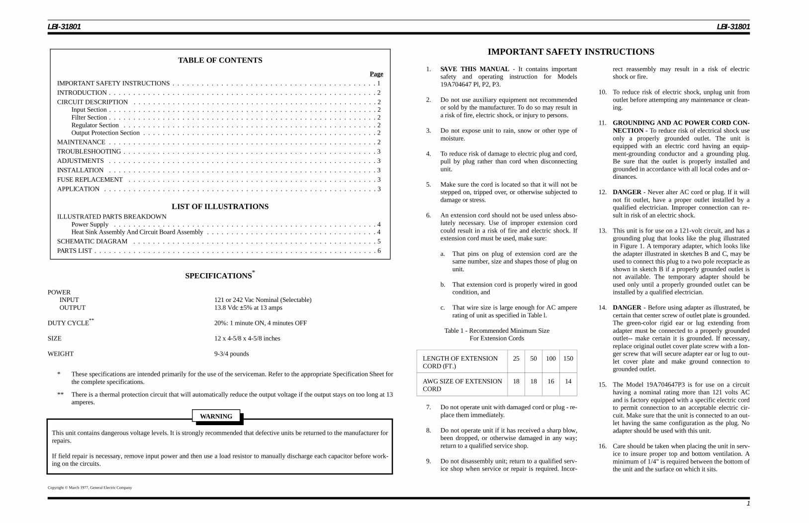
TABLE OF CONTENTS
PageIMPORTANT SAFETY INSTRUCTIONS . . . . . . . . . . . . . . . . . . . . . . . . . . . . . . . . . . . . . . . . . . 1
INTRODUCTION . . . . . . . . . . . . . . . . . . . . . . . . . . . . . . . . . . . . . . . . . . . . . . . . . . . . . . . 2
CIRCUIT DESCRIPTION . . . . . . . . . . . . . . . . . . . . . . . . . . . . . . . . . . . . . . . . . . . . . . . . . . 2Input Section . . . . . . . . . . . . . . . . . . . . . . . . . . . . . . . . . . . . . . . . . . . . . . . . . . . . . . . 2Filter Section . . . . . . . . . . . . . . . . . . . . . . . . . . . . . . . . . . . . . . . . . . . . . . . . . . . . . . . 2Regulator Section . . . . . . . . . . . . . . . . . . . . . . . . . . . . . . . . . . . . . . . . . . . . . . . . . . . . 2Output Protection Section . . . . . . . . . . . . . . . . . . . . . . . . . . . . . . . . . . . . . . . . . . . . . . . . 2
MAINTENANCE . . . . . . . . . . . . . . . . . . . . . . . . . . . . . . . . . . . . . . . . . . . . . . . . . . . . . . . 2
TROUBLESHOOTING . . . . . . . . . . . . . . . . . . . . . . . . . . . . . . . . . . . . . . . . . . . . . . . . . . . . 3
ADJUSTMENTS . . . . . . . . . . . . . . . . . . . . . . . . . . . . . . . . . . . . . . . . . . . . . . . . . . . . . . . 3
INSTALLATION . . . . . . . . . . . . . . . . . . . . . . . . . . . . . . . . . . . . . . . . . . . . . . . . . . . . . . . 3
FUSE REPLACEMENT . . . . . . . . . . . . . . . . . . . . . . . . . . . . . . . . . . . . . . . . . . . . . . . . . . . 3
APPLICATION . . . . . . . . . . . . . . . . . . . . . . . . . . . . . . . . . . . . . . . . . . . . . . . . . . . . . . . . 3
LIST OF ILLUSTRA TIONSILLUSTRATED PARTS BREAKDOWN
Power Supply . . . . . . . . . . . . . . . . . . . . . . . . . . . . . . . . . . . . . . . . . . . . . . . . . . . . . . 4Heat Sink Assembly And Circuit Board Assembly . . . . . . . . . . . . . . . . . . . . . . . . . . . . . . . . . . . 4
SCHEMATIC DIAGRAM . . . . . . . . . . . . . . . . . . . . . . . . . . . . . . . . . . . . . . . . . . . . . . . . . . 5
PARTS LIST . . . . . . . . . . . . . . . . . . . . . . . . . . . . . . . . . . . . . . . . . . . . . . . . . . . . . . . . . . 6
SPECIFICATIONS *
POWERINPUT 121 or 242 Vac Nominal (Selectable)OUTPUT 13.8 Vdc ±5% at 13 amps
DUTY CYCLE** 20%: 1 minute ON, 4 minutes OFF
SIZE 12 x 4-5/8 x 4-5/8 inches
WEIGHT 9-3/4 pounds
* These specifications are intended primarily for the use of the serviceman. Refer to the appropriate Specification Sheet forthe complete specifications.
** There is a thermal protection circuit that will automatically reduce the output voltage if the output stays on too long at 13amperes.
This unit contains dangerous voltage levels. It is strongly recommended that defective units be returned to the manufacturer forrepairs.
If field repair is necessary, remove input power and then use a load resistor to manually discharge each capacitor before work-ing on the circuits.
WARNING
LBI-31801 LBI-31801
1

The following are reproductions of labels on the productrelating to product safety.
INTRODUCTION
This unit is a linear power supply with a step-down trans-former input, capacitor filter section and linear transistor regu-lator on the output. It converts 121/242 volts RMS AC to 13.8volts DC at 13 amperes maximum.
The AC input voltage is transformed to approximately 24volts AC, rectified and filtered by a capacitor filter. The filteredDC voltage is then regulated. This circuit monitors the outputvoltage, compares this voltage with a reference voltage andcorrects the output to provide 13.8 volts DC for varying loadcurrents. Output overvoltage and overtemperature protectionare provided.
CIRCUIT DESCRIPTION
INPUT SECTION
The input circuitry consists of fuse Fl, switch S1, trans-former T1, MOV’s VI-V3 and rectifiers D1 - D3. The trans-former isolates and reduces the 121/242 Vac input toapproximately 24 Vac. The metal oxide varistors provide pro-tection for voltage surges that appear on the AC input line.Bridge rectifier D I provides DC power to the high current fil-ter section. Diodes D2 and D3 provide DC power for the inte-grated circuit regulator filter. The AC input voltage isselectable between 121 Vac and 242 Vac by selecting properprimary windings of the transformer. Wire nuts allow the trans-former leads to be wired properly. See the schematic diagramfor further details.
FILTER SECTION
The high current filter section consists of capacitor CI. Re-sistor RI (two .075 ohms resistors) provides surge protection atturn-on for DI.
The regulator filter section consists of capacitor C2. Ca-pacitor C3 prevents the regulator IC1 from oscillating. Thevoltage at the input of IC1 normally is about 2 volts higherthan the high current filter section when the supply is underload. This allows the supplys’ output to remain regulated atlow AC input voltages. It should be noted that a problem withbridge DI may also upset the IC regulators supply due to thecurrent path of the regulators rectifier/filter section.
REGULATOR SECTION
The regulator section consists of the control regulator 1C 1which contains a reference voltage source plus comparator cir-cuitry. This circuitry monitors the feedback voltage developed
by resistors R4 and R5. This voltage is compared to the IC in-ternal reference at pin 4 of IC 1. IC 1 then adjusts the current totransistors to achieve an output voltage of I 3.8 volts DC on theemitters of Q1 and Q2. Capacitor C4 smoothes the output ofICI and prevents QI and Q2 from oscillating. Capacitor C5 fil-ters the regulator output to provide low ripple and good tran-sient response.
OUTPUT PROTECTION SECTION
The output protection consists of an overvoltage monitorcircuit comprised of zener diode D4 and resistors R6 and R7.This network divides the output voltage down and triggersSCR1 when the output voltage exceeds 16 volts. When SCR 1fires the output is shorted through power resistor R8 and theinput fuse is blown. Capacitor C6 prevents SCRl from falsetriggering on noise. If the output is greatly overloaded, the in-put fuse will blow. Small overloads which do not blow the fusebut lead to overheating are protected against by the tempera-ture monitoring circuitry in the IC regulator. When the heatsinktemperature exceeds 150 degrees C, the IC regulator will shutdown the output section. After the heatsink cools, the circuitryresets automatically.
OPERATION
I. Connect 13 Vdc output to the load using the matingconnector.
2. With the ON/OFF switch in OFF position, connectAC power cord to a 120 Vac power source.
3. Place the ON/OFF switch to the ON position to turnon the power supply.
MAINTENANCE
Figure 1 - Grounding Methods
IMPORTANT SAFETY INST RUCTIONS
OUTPUT USES CLASS 1WIRING ONLY FOR
13.8 VDC & 13 A AT 20%DUTY CYCLE
1 MIN. ON, 4 MIN. OFF
This unit contains dangerous voltage levels. It isstrongly recommended that defective units be returnedto the manufacturer for repairs.
If field repair is necessary, remove input power and thenuse a load resistor to manually discharge each capacitorbefore working on the circuits.
WARNING
LBI-31801 LBI-31801
2

For disassembly, remove 4 screws and lift off top cover.This disassembly is required before working on this powersupply. When replacing any component be certain to use anidentical component Thermal joint component is required un-der D1, Q1, Q2, IC1 and SCR1. R8 must be spaced above theprinted circuit board by 3/32 inch minimum. Observe wirerouting when resoldering circuits. Failure to do so may lead toexcessive ripple or poor regulation.
Should the overvoltage monitor circuit be suspected ofblowing the fuse proceed as follows:
1. Connect the supply to a resistive load (not the deskstation!).
2. Remove resistor R8 from the circuit by disconnectingone end.
3. Turn on the supply and observe whether the fuseblows. If the fuse no longer blows the overvoltagemonitor circuit was the cause.
TROUBLESHOOTING
The checks in the following tables should be followedwhen troubleshooting a suspected defective power supply.When a component or assembly has been identified as beingdefective, replace the defective component and also check as-sociated components before apply power to the unit in theevent that a series of components are defective.
When replacing any component be certain to use an identi-cal component. Thermal joint component is required under D1,Q1, Q2, IC1 and SCR1. R8 must be spaced 3/32 inch abovethe printed circuit board. Observe wire routing when resolder-ing circuits. Failure to do so may lead to excessive ripple orpoor regulation.
Recommended test equipment for maintenance of thispower supply includes:
• Digital multimeter
• 50 amp DC meter
• Resistive load
• a Oscilloscope
ADJUSTMENTS
This power supply has no adjustments or controls otherthan the ON/OFF switch.
INSTALLA TION
The power supply can be mounted using the mountingholes on the chassis.
The power supply is designed for operation from either a121 Vac or 242 Vac source. Before connecting the power sup-ply measure the source voltage and then connect input trans-former accordingly. Refer to the Schematic diagram for details.
FUSE REPLACEMENT
To replace a defective fuse, perform the following proce-dure:
1. Place ON/OFF switch to OFF position.
2. Remove cap from fuse holder and replace fuse with asimilar type and size [4 amp, 250V (121 Vac input),2.5 amp, 250V (242 Vac input)].
3. Replace cap and place ON/OFF switch to ON posi-tion.
If trouble persists, check with a qualified service personnel.
POWER SUPPLY VOLTAGE READING
LOCATION READING (TYPICAL)
C1 PLUS APPROXIMATELY +25 VOLTS DC
C2 PLUS APPROXIMATELY +27 VOLTS DC
IC1 PIN4 APPROXIMATELY +4.7 VOLTS DC
OUTPUT +13.1 TO 14.1 VOLTS DC
IC1 PIN 3 0.7 VOLTS ABOVE OUTPUT
APPLICATION
The 19A704647P2 and P3 units include mounting feetand omits the mounting bracket. A mating connector andmating male contacts are provided to mate with the 13 Vdcoutput connector.
The 19A70467P3 unit operates from a 242 Vac input. Apower cord is supplied less a power plug (customer pro-vided) on end of cord.
In some cases a 220k Ohm resistor R9 has been paral-leled with R5 at the factory in order to achieve the re-quired output voltage.
NOTE
Insure that ventilation holes in the unit are not ob-structed when the unit is mounted or in operation.
NOTE
TROUBLESHOOTING TABLE
SYMPTOM AREA TO CHECK
FUSE BLOWS 1) shorted output2) 230 volts AC applied with 115 volt tap selected3) shorted D1, Q1, Q2, T1, C1, SCR14) overvoltaged on output causing SCR1 to fire
NO OUTPUT 1) shorted output2) proper voltage range selected3) output properly connected4) overtemperature shutdown5) failed Q1, Q2, D1, IC1
OUTPUT VOLTAGE LOW 1) proper input voltage range selected2) output overloaded3) ICI failure
OUTPUT VOLTAGE HIGH 1) failed SCR1, failed IC1, failed Q1
Figure 2 - Top View With Cover Removed
LBI-31801 LBI-31801
3

POWER SUPPLY
ILLUSTRATED PARTS BREAKDOWNLBI-31801 LBI-31801
4

HEAT SINK ASSEMBLYAND CIRCUIT BOARD ASSEMBLY
ILLUSTRATED PARTS BREAKDOWN AND OUTLINE DIAGRAMLBI-31801 LBI-31801
5
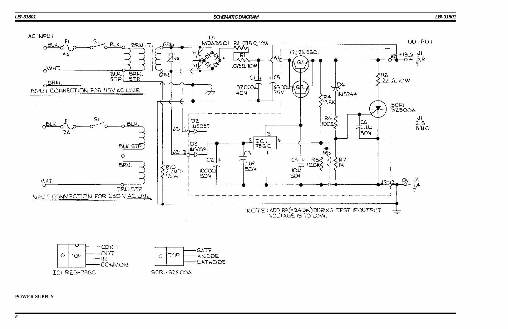
SCHEMATIC DIAGRAM
POWER SUPPLY
LBI-31801 LBI-31801
6

PARTS LISTLBI-31801 LBI-31801
7