lbp based edge-texture features for object recognition · lbp based edge-texture features for...
TRANSCRIPT

1057-7149 (c) 2013 IEEE. Personal use is permitted, but republication/redistribution requires IEEE permission. Seehttp://www.ieee.org/publications_standards/publications/rights/index.html for more information.
This article has been accepted for publication in a future issue of this journal, but has not been fully edited. Content may change prior to final publication. Citation information: DOI10.1109/TIP.2014.2310123, IEEE Transactions on Image Processing
1
LBP Based Edge-Texture Features for ObjectRecognition
Amit Satpathy, Member, IEEE, Xudong Jiang, Senior Member, IEEE, and How-Lung Eng, Member, IEEE
Abstract—This paper proposes two sets of novel edge-texturefeatures, Discriminative Robust Local Binary Pattern (DRLBP)and Ternary Pattern (DRLTP), for object recognition. By in-vestigating the limitations of Local Binary Pattern (LBP), LocalTernary Pattern (LTP) and Robust LBP (RLBP), DRLBP andDRLTP are proposed as new features. They solve the problemof discrimination between a bright object against a dark back-ground and vice-versa inherent in LBP and LTP. DRLBP alsoresolves the problem of RLBP whereby LBP codes and theircomplements in the same block are mapped to the same code.Furthermore, the proposed features retain contrast informationnecessary for proper representation of object contours that LBP,LTP and RLBP discard. Our proposed features are tested on7 challenging data sets - INRIA Human, Caltech Pedestrian,UIUC Car, Caltech 101, Caltech 256, Brodatz and KTH-TIPS2-a. Results demonstrate that the proposed features outperformthe compared approaches on most data sets.
Index Terms—object recognition, local binary pattern, localternary pattern, feature extraction, texture.
I. INTRODUCTION
CATEGORY recognition and detection are 2 parts ofobject recognition. The objective of category recognition
is to classify an object into one of several predefined cate-gories. The goal of detection is to distinguish objects from thebackground. There are various object recognition challenges.Typically, objects have to be detected against cluttered, noisybackgrounds and other objects under different illuminationand contrast environments. Proper feature representation is acrucial step in an object recognition system as it improves per-formance by discriminating the object from the background orother objects in different lightings and scenarios. Furthermore,a good feature also simplifies the classification framework.
Object recognition features are categorized into two groups- sparse and dense representations [7]. For sparse featurerepresentations, interest-point detectors are used to identifystructures such as corners and blobs on the object. A featureis created for the image patch around each point. Popularfeature representations include Scale-Invariant Feature Trans-form (SIFT) [16], [30], Speeded Up Robust Feature [3], LocalSteering Kernel [49], Principal Curvature-Based Regions [9],
Copyright (c) 2013 IEEE. Personal use of this material is permitted.However, permission to use this material for any other purposes must beobtained from the IEEE by sending a request to [email protected].
A. Satpathy is with Institute for Infocomm Research, Agency for Science,Technology & Research, 1 Fusionopolis Way, Connexis, Singapore 138632.E-mail: [email protected]
X. Jiang is with the School of Electrical and Electronics Engineering,Nanyang Technological University, Nanyang Link, Singapore 639798. E-mail:[email protected]
H.-L. Eng is with Zweec Analytics, 67 Ayer Rajah Crescent, 03-23/24,Singapore 139950. E-mail: [email protected]
Region Self-Similarity features [33], [50], Sparse Color [51]and the sparse parts-based representation [1]. A comprehensiveevaluation of sparse features can be found in [34], [35].
Dense feature representations, which are extracted at fixedlocations densely in a detection window, are gaining popularityas they describe objects richly compared to sparse feature rep-resentations. Various feature representations such as Wavelet[40], Haar-like features [55], Histogram of Oriented Gradients(HOG) [8], [56], Extended Histogram of Gradients [44]–[46], [48], Feature Context [57], Local Binary Pattern (LBP)[2], [22], [47], Local Ternary Pattern (LTP) [52], Geometric-blur [59] and Local Edge Orientation Histograms [25] havebeen proposed over recent years. Dense SIFT has also beenproposed to alleviate the sparse representation problems [4],[24], [53].
LBP is the most popular texture classification feature [18],[20], [21], [27], [38], [41], [42], [62]. It has also shownexcellent face detection performance [2], [19], [26], [52], [61].It is robust to illumination and contrast variations as it onlyconsiders the signs of the pixel differences. HistogrammingLBP codes makes the descriptor resistant to translations withinthe histogramming neighbourhood. However, it is sensitiveto noise and small fluctuations of pixel values. To handlethis, Local Ternary Pattern (LTP) has been proposed [52].In comparison to LBP, it has 2 thresholds which creates 3different states as compared to 2 in LBP. It is more resistantto noise and small pixel value variations compared to LBP.Like LBP, it has also been used for texture classification andface detection [13], [23], [28], [42], [52], [60].
However, for object recognition, LBP and LTP present twoissues. They differentiate a bright object against a dark back-ground and vice versa. This increases the object intra-classvariations which is undesirable for most object recognitions.Nguyen et al. [37] propose Robust LBP (RLBP) to map a LBPcode and its complement to the minimum of both to solve theproblem. However, in the same block, RLBP also maps tothe same value. For some different local structures, a similarfeature is obtained. Hence, it is unable to differentiate them.
Different objects have different shapes and textures. It istherefore desirable to represent objects using both textureand edge information. However, in order to be robust toillumination and contrast variations, LBP, LTP and RLBPdo not differentiate between a weak contrast local patternand a similar strong one. They only capture texture infor-mation. Object contours, which also contain discriminatoryinformation, tend to be situated in strong contrast regions.Therefore, by discarding contrast information, contours maynot be effectively represented.

1057-7149 (c) 2013 IEEE. Personal use is permitted, but republication/redistribution requires IEEE permission. Seehttp://www.ieee.org/publications_standards/publications/rights/index.html for more information.
This article has been accepted for publication in a future issue of this journal, but has not been fully edited. Content may change prior to final publication. Citation information: DOI10.1109/TIP.2014.2310123, IEEE Transactions on Image Processing
2
5 10 15 20 25 30 35 40 45 50 550
0.05
0.1
0.15
0.2
0.25
0.3
0.35
0.4
5 10 15 20 25 300
0.05
0.1
0.15
0.2
0.25
0.3
0.35
0.4
10 20 30 40 50 60 70 80 90 100 1100
0.05
0.1
0.15
0.2
0.25
0.3
0.35
0.4
10 20 30 40 50 60 70 800
0.05
0.1
0.15
0.2
0.25
0.3
0.35
0.4
Similarity Score 0.376 1.000 0.354 1.000
5 10 15 20 25 30 35 40 45 50 550
0.05
0.1
0.15
0.2
0.25
0.3
0.35
0.4
5 10 15 20 25 300
0.05
0.1
0.15
0.2
0.25
0.3
0.35
0.4
10 20 30 40 50 60 70 80 90 100 1100
0.05
0.1
0.15
0.2
0.25
0.3
0.35
0.4
10 20 30 40 50 60 70 800
0.05
0.1
0.15
0.2
0.25
0.3
0.35
0.4
(a) LBP (b) RLBP (c) LTP (d) RLTP
Fig. 1. Problem of Local Binary Patterns (LBP) and Local Ternary Patterns (LTP) and their solutions by Robust LBP (RLBP) and Robust LTP (RLTP). Thesimilarity score between histograms is measured by histogram intersection.
In this paper, we propose two sets of novel edge-texture fea-tures, Discriminative Robust LBP (DRLBP) and LTP. The pro-posed features solve the issues of LBP, LTP and RLBP. Theyalleviate the intensity reversal problem of object and back-ground. Furthermore, DRLBP discriminates local structuresthat RLBP misrepresent. In addition, the proposed featuresretain the contrast information of image patterns. They containboth edge and texture information which is desirable for objectrecognition. We present comprehensive experimental resultson 7 data sets - INRIA Human, Caltech Pedestrian, UIUCCar, Caltech 101, Caltech 256, Brodatz and KTH-TIPS2-a.Results indicate that the proposed features outperform LBP,LTP and RLBP and perform better than other approaches incomparison on most data sets.
II. DISCRIMINATIVE ROBUST LOCAL BINARY ANDTERNARY PATTERNS
A. Limitations of LBP, LTP and Robust LBP
The LBP [38] code at location (x, y) is computed as follows:
LBPx,y =
B−1∑b=0
s(pb − pc)2b, (1)
s(z) =
{1, z ≥ 00, z < 0
where pc is the pixel value at (x, y), pb is the pixel valueestimated using bilinear interpolation from neighbouring pixelsin the b-th location on the circle of radius R around pc andB is the total number of neighbouring pixels. A 2B-bin blockhistogram is computed. There are some patterns that occurmore frequently than others and the number of state transitionsbetween 0 and 1 for them are at most two [38]. Such patternsare called uniform patterns and the rest as non-uniform. Bygiving each uniform pattern a bin and collating all non-uniformpatterns into a single bin, the bin number is reduced. For B =8, it is reduced from 256 to 59.
In [38], another LBP variant, rotation-invariant LBP, isproposed for texture classification. However, our focus is onobject recognition. Different objects exhibit different shapes
that are captured by the orientation information. It is beneficialto retain these inter-class variations to model the objects. Usingrotation-invariant features will significantly reduce the inter-class variations and oversimplify the object models. Therefore,in our work, rotation-invariance is not considered.
LBP is invariant to monotonic intensity changes. Hence, itis robust to illumination and contrast variations. However, it issensitive to noise and small pixel value fluctuations. Therefore,LTP [52] has been proposed to handle this situation. The LTPcode at location (x, y) is computed as follows:
LTPx,y =
B−1∑b=0
s′(pb − pc)3b, (2)
s′(z) =
1, z ≥ T0, −T < z < T−1, z ≤ −T
where T is a user-defined threshold. As defined by s′(z), LTPhas 3 states while LBP has two. A 3B-bin block histogram iscomputed. For B = 8, the histogram has 6561 bins which isvery high-dimensional. Hence, in [52], the authors propose tosplit the LTP code into its “upper” and “lower” LBP codes.The “upper” code, ULBP , is computed as follows:
ULBP =
B−1∑b=0
f(pb − pc)2b, (3)
f(z) =
{1, z ≥ T0, otherwise
The “lower” code, LLBP , is computed as follows:
LLBP =
B−1∑b=0
f ′(pb − pc)2b, (4)
f ′(z) =
{1, z ≤ −T0, otherwise
By doing so, the bin number is reduced from 6561 to 512.Using uniform LBP codes, it is further reduced to 118.
An issue with LBP and LTP is that they differentiate abright object against a dark background and vice-versa. This
1057-7149 (c) 2013 IEEE. Personal use is permitted, but republication/redistribution requires IEEE permission. Seehttp://www.ieee.org/publications_standards/publications/rights/index.html for more information.
This article has been accepted for publication in a future issue of this journal, but has not been fully edited. Content may change prior to final publication. Citation information: DOI10.1109/TIP.2014.2310123, IEEE Transactions on Image Processing
3
(a1) (a2) (b1) (b2) (c1) (c2)
5 10 15 20 25 300
0.05
0.1
0.15
0.2
0.25
0.3
0.35
0.4
5 10 15 20 25 300
0.05
0.1
0.15
0.2
0.25
0.3
0.35
0.4
5 10 15 20 25 300
0.05
0.1
0.15
0.2
0.25
0.3
0.35
0.4
5 10 15 20 25 300
0.05
0.1
0.15
0.2
0.25
0.3
0.35
0.4
5 10 15 20 25 300
0.05
0.1
0.15
0.2
0.25
0.3
0.35
0.4
5 10 15 20 25 300
0.05
0.1
0.15
0.2
0.25
0.3
0.35
0.4
(a3) (b3) (c3)
10 20 30 40 50 60 70 800
0.05
0.1
0.15
0.2
0.25
0.3
0.35
0.4
10 20 30 40 50 60 70 800
0.05
0.1
0.15
0.2
0.25
0.3
0.35
0.4
10 20 30 40 50 60 70 800
0.05
0.1
0.15
0.2
0.25
0.3
0.35
0.4
10 20 30 40 50 60 70 800
0.05
0.1
0.15
0.2
0.25
0.3
0.35
0.4
10 20 30 40 50 60 70 800
0.05
0.1
0.15
0.2
0.25
0.3
0.35
0.4
10 20 30 40 50 60 70 800
0.05
0.1
0.15
0.2
0.25
0.3
0.35
0.4
(a4) (b4) (c4)
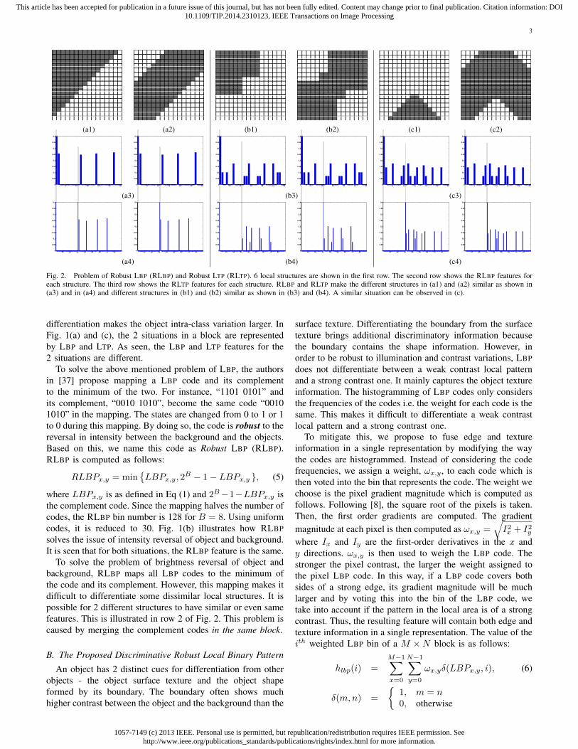
Fig. 2. Problem of Robust LBP (RLBP) and Robust LTP (RLTP). 6 local structures are shown in the first row. The second row shows the RLBP features foreach structure. The third row shows the RLTP features for each structure. RLBP and RLTP make the different structures in (a1) and (a2) similar as shown in(a3) and in (a4) and different structures in (b1) and (b2) similar as shown in (b3) and (b4). A similar situation can be observed in (c).
differentiation makes the object intra-class variation larger. InFig. 1(a) and (c), the 2 situations in a block are representedby LBP and LTP. As seen, the LBP and LTP features for the2 situations are different.
To solve the above mentioned problem of LBP, the authorsin [37] propose mapping a LBP code and its complementto the minimum of the two. For instance, “1101 0101” andits complement, “0010 1010”, become the same code “00101010” in the mapping. The states are changed from 0 to 1 or 1to 0 during this mapping. By doing so, the code is robust to thereversal in intensity between the background and the objects.Based on this, we name this code as Robust LBP (RLBP).RLBP is computed as follows:
RLBPx,y = min{LBPx,y, 2
B − 1− LBPx,y }, (5)
where LBPx,y is as defined in Eq (1) and 2B−1−LBPx,y isthe complement code. Since the mapping halves the number ofcodes, the RLBP bin number is 128 for B = 8. Using uniformcodes, it is reduced to 30. Fig. 1(b) illustrates how RLBPsolves the issue of intensity reversal of object and background.It is seen that for both situations, the RLBP feature is the same.
To solve the problem of brightness reversal of object andbackground, RLBP maps all LBP codes to the minimum ofthe code and its complement. However, this mapping makes itdifficult to differentiate some dissimilar local structures. It ispossible for 2 different structures to have similar or even samefeatures. This is illustrated in row 2 of Fig. 2. This problem iscaused by merging the complement codes in the same block.
B. The Proposed Discriminative Robust Local Binary Pattern
An object has 2 distinct cues for differentiation from otherobjects - the object surface texture and the object shapeformed by its boundary. The boundary often shows muchhigher contrast between the object and the background than the
surface texture. Differentiating the boundary from the surfacetexture brings additional discriminatory information becausethe boundary contains the shape information. However, inorder to be robust to illumination and contrast variations, LBPdoes not differentiate between a weak contrast local patternand a strong contrast one. It mainly captures the object textureinformation. The histogramming of LBP codes only considersthe frequencies of the codes i.e. the weight for each code is thesame. This makes it difficult to differentiate a weak contrastlocal pattern and a strong contrast one.
To mitigate this, we propose to fuse edge and textureinformation in a single representation by modifying the waythe codes are histogrammed. Instead of considering the codefrequencies, we assign a weight, ωx,y , to each code which isthen voted into the bin that represents the code. The weight wechoose is the pixel gradient magnitude which is computed asfollows. Following [8], the square root of the pixels is taken.Then, the first order gradients are computed. The gradientmagnitude at each pixel is then computed as ωx,y =
√I2x + I2y
where Ix and Iy are the first-order derivatives in the x andy directions. ωx,y is then used to weigh the LBP code. Thestronger the pixel contrast, the larger the weight assigned tothe pixel LBP code. In this way, if a LBP code covers bothsides of a strong edge, its gradient magnitude will be muchlarger and by voting this into the bin of the LBP code, wetake into account if the pattern in the local area is of a strongcontrast. Thus, the resulting feature will contain both edge andtexture information in a single representation. The value of theith weighted LBP bin of a M ×N block is as follows:
hlbp(i) =
M−1∑x=0
N−1∑y=0
ωx,yδ(LBPx,y, i), (6)
δ(m,n) =
{1, m = n0, otherwise
1057-7149 (c) 2013 IEEE. Personal use is permitted, but republication/redistribution requires IEEE permission. Seehttp://www.ieee.org/publications_standards/publications/rights/index.html for more information.
This article has been accepted for publication in a future issue of this journal, but has not been fully edited. Content may change prior to final publication. Citation information: DOI10.1109/TIP.2014.2310123, IEEE Transactions on Image Processing
4
(a) (b) (c) (d) (e) (f)
LB
P
5 10 15 20 25 30 35 40 45 50 550
0.05
0.1
0.15
0.2
0.25
0.3
0.35
0.4
5 10 15 20 25 30 35 40 45 50 550
0.05
0.1
0.15
0.2
0.25
0.3
0.35
0.4
5 10 15 20 25 30 35 40 45 50 550
0.05
0.1
0.15
0.2
0.25
0.3
0.35
0.4
5 10 15 20 25 30 35 40 45 50 550
0.05
0.1
0.15
0.2
0.25
0.3
0.35
0.4
5 10 15 20 25 30 35 40 45 50 550
0.05
0.1
0.15
0.2
0.25
0.3
0.35
0.4
5 10 15 20 25 30 35 40 45 50 550
0.05
0.1
0.15
0.2
0.25
0.3
0.35
0.4
RL
BP
5 10 15 20 25 300
0.05
0.1
0.15
0.2
0.25
0.3
0.35
0.4
5 10 15 20 25 300
0.05
0.1
0.15
0.2
0.25
0.3
0.35
0.4
5 10 15 20 25 300
0.05
0.1
0.15
0.2
0.25
0.3
0.35
0.4
5 10 15 20 25 300
0.05
0.1
0.15
0.2
0.25
0.3
0.35
0.4
5 10 15 20 25 300
0.05
0.1
0.15
0.2
0.25
0.3
0.35
0.4
5 10 15 20 25 300
0.05
0.1
0.15
0.2
0.25
0.3
0.35
0.4
DR
LB
P
10 20 30 40 50 600
0.05
0.1
0.15
0.2
0.25
10 20 30 40 50 600
0.05
0.1
0.15
0.2
0.25
10 20 30 40 50 600
0.05
0.1
0.15
0.2
0.25
10 20 30 40 50 600
0.05
0.1
0.15
0.2
0.25
10 20 30 40 50 600
0.05
0.1
0.15
0.2
0.25
10 20 30 40 50 600
0.05
0.1
0.15
0.2
0.25
LTP
10 20 30 40 50 60 70 80 90 100 1100
0.05
0.1
0.15
0.2
0.25
0.3
0.35
0.4
10 20 30 40 50 60 70 80 90 100 1100
0.05
0.1
0.15
0.2
0.25
0.3
0.35
0.4
10 20 30 40 50 60 70 80 90 100 1100
0.05
0.1
0.15
0.2
0.25
0.3
0.35
0.4
10 20 30 40 50 60 70 80 90 100 1100
0.05
0.1
0.15
0.2
0.25
0.3
0.35
0.4
10 20 30 40 50 60 70 80 90 100 1100
0.05
0.1
0.15
0.2
0.25
0.3
0.35
0.4
10 20 30 40 50 60 70 80 90 100 1100
0.05
0.1
0.15
0.2
0.25
0.3
0.35
0.4
RLT
P
10 20 30 40 50 60 70 800
0.05
0.1
0.15
0.2
0.25
0.3
0.35
0.4
10 20 30 40 50 60 70 800
0.05
0.1
0.15
0.2
0.25
0.3
0.35
0.4
10 20 30 40 50 60 70 800
0.05
0.1
0.15
0.2
0.25
0.3
0.35
0.4
10 20 30 40 50 60 70 800
0.05
0.1
0.15
0.2
0.25
0.3
0.35
0.4
10 20 30 40 50 60 70 800
0.05
0.1
0.15
0.2
0.25
0.3
0.35
0.4
10 20 30 40 50 60 70 800
0.05
0.1
0.15
0.2
0.25
0.3
0.35
0.4
DR
LTP
20 40 60 80 100 120 140 1600
0.05
0.1
0.15
0.2
0.25
20 40 60 80 100 120 140 1600
0.05
0.1
0.15
0.2
0.25
20 40 60 80 100 120 140 1600
0.05
0.1
0.15
0.2
0.25
20 40 60 80 100 120 140 1600
0.05
0.1
0.15
0.2
0.25
20 40 60 80 100 120 140 1600
0.05
0.1
0.15
0.2
0.25
20 40 60 80 100 120 140 1600
0.05
0.1
0.15
0.2
0.25
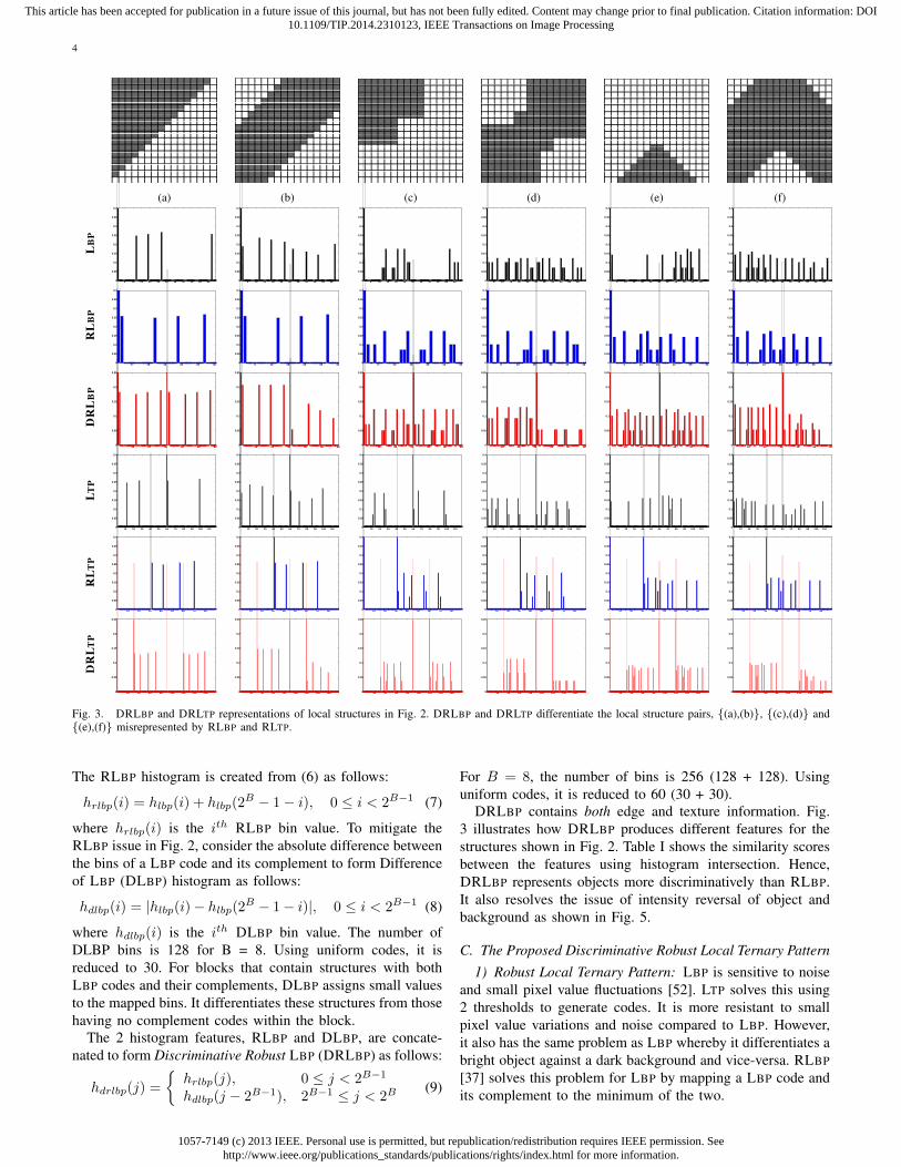
Fig. 3. DRLBP and DRLTP representations of local structures in Fig. 2. DRLBP and DRLTP differentiate the local structure pairs, {(a),(b)}, {(c),(d)} and{(e),(f)} misrepresented by RLBP and RLTP.
The RLBP histogram is created from (6) as follows:
hrlbp(i) = hlbp(i) + hlbp(2B − 1− i), 0 ≤ i < 2B−1 (7)
where hrlbp(i) is the ith RLBP bin value. To mitigate theRLBP issue in Fig. 2, consider the absolute difference betweenthe bins of a LBP code and its complement to form Differenceof LBP (DLBP) histogram as follows:
hdlbp(i) = |hlbp(i)− hlbp(2B − 1− i)|, 0 ≤ i < 2B−1 (8)
where hdlbp(i) is the ith DLBP bin value. The number ofDLBP bins is 128 for B = 8. Using uniform codes, it isreduced to 30. For blocks that contain structures with bothLBP codes and their complements, DLBP assigns small valuesto the mapped bins. It differentiates these structures from thosehaving no complement codes within the block.
The 2 histogram features, RLBP and DLBP, are concate-nated to form Discriminative Robust LBP (DRLBP) as follows:
hdrlbp(j) =
{hrlbp(j), 0 ≤ j < 2B−1
hdlbp(j − 2B−1), 2B−1 ≤ j < 2B(9)
For B = 8, the number of bins is 256 (128 + 128). Usinguniform codes, it is reduced to 60 (30 + 30).
DRLBP contains both edge and texture information. Fig.3 illustrates how DRLBP produces different features for thestructures shown in Fig. 2. Table I shows the similarity scoresbetween the features using histogram intersection. Hence,DRLBP represents objects more discriminatively than RLBP.It also resolves the issue of intensity reversal of object andbackground as shown in Fig. 5.
C. The Proposed Discriminative Robust Local Ternary Pattern1) Robust Local Ternary Pattern: LBP is sensitive to noise
and small pixel value fluctuations [52]. LTP solves this using2 thresholds to generate codes. It is more resistant to smallpixel value variations and noise compared to LBP. However,it also has the same problem as LBP whereby it differentiates abright object against a dark background and vice-versa. RLBP[37] solves this problem for LBP by mapping a LBP code andits complement to the minimum of the two.

1057-7149 (c) 2013 IEEE. Personal use is permitted, but republication/redistribution requires IEEE permission. Seehttp://www.ieee.org/publications_standards/publications/rights/index.html for more information.
This article has been accepted for publication in a future issue of this journal, but has not been fully edited. Content may change prior to final publication. Citation information: DOI10.1109/TIP.2014.2310123, IEEE Transactions on Image Processing
5
TABLE ISIMILARITY SCORES FOR LOCAL STRUCTURE PAIRS IN FIG. 3.
Approach Similarity Score{(a),(b)} {(c),(d)} {(e),(f)}
LBP 0.280 0.366 0.445RLBP 1.000 1.000 1.000DRLBP 0.109 0.169 0.111LTP 0.280 0.354 0.354RLTP 1.000 1.000 1.000DRLTP 0.109 0.148 0.112
However, RLBP cannot be applied to ULBP and LLBPof LTP. For a pair of object/background intensity invertedpatterns, their ULBP codes are not complements. Similarly,their LLBP codes are also not complements. This is illus-trated in Fig. 4 where 2 different cases of object/backgroundinverted intensity patterns are shown. In Fig. 4(a1) and (a2),a case illustrating a neighbourhood, where all 3 LTP statesoccur, is shown. From the two LTP codes, it is observed thatthe 2 patterns are simply intensity inverted. However, theircorresponding ULBP codes are not complements. Similarly,their corresponding LLBP codes are also not complements.A similar situation is observed in (b1) and (b2) where only2 LTP states are present. The ULBP and LLBP codes arenot complements. Hence, RLBP cannot be applied to ULBPand LLBP to obtain a feature that is robust to the reversal inintensity between the objects and background.
In order to alleviate this problem of LTP, we need toanalyze the 3-state LTP definition in (2): 1, 0 and -1. Thestate of 0 represent regions of small variations, noise anduniform regions. It will not change when there is an inversionof brightness between the background and objects as thevariations remain the same. Therefore, for a pair of brightnessinverted object/background patterns, only the state of -1 isinverted to 1 and vice-versa. Hence, for every LTP code, wecan find its corresponding inverted code. For instance, “-1-1001100” has an inverted code “1100 -1-100”. If both codes aremapped to a same bin, a feature that is robust to the reversal inintensity between the objects and background can be obtained.
In this paper, the maximum of a LTP code and its invertedrepresentation is chosen. We name it as Robust LTP (RLTP).Mathematically, RLTP is formulated as follows:
RLTPx,y = max {LTPx,y,−LTPx,y } (10)
The RLTP code can then be split into “upper” and “lower” LBPcodes. The “upper” code, URLBP , is expressed as follows:
URLBP =
B−1∑b=0
h(RLTPx,y,b)2b, (11)
h(z) =
{1, z = 10, otherwise
where RLTPx,y,b represents the RLTP state value at the b-thlocation. The “lower” code, LRLBP , is computed as follows:
LRLBP =
B−1∑b=0
h′(RLTPx,y,b)2b, (12)
h′(z) =
{1, z = −10, otherwise
(a1) (a2)
(b1) (b2)
Fig. 4. Illustration of ULBP and LLBP codes of LTP for 2 situationswhere the intensities are reversed. It can be seen that the ULBP and LLBPcodes are reversed for the 2 situations.
The most significant bit of LRLBP is 0 as the state at (B−1)-th location of RLTP is either 0 or 1. Fig. 1(d) illustrates howRLTP alleviates the brightness reversal problem of object andbackground. It is observed that for the two situations, the RLTPfeatures are the same.
However, similar to RLBP in Section II-A, RLTP also mapsa LTP code and its inverted representation in the same blockto the same value. This is illustrated in Fig. 2 in the last row.
2) Discriminative Robust Local Ternary Patterns: LTP andRLTP are also robust to illumination and contrast variationsand only capture texture information. Hence, the weightingscheme in Section II-B is also used. The kth weighted LTPbin value of a M ×N image block is as follows:
hltp(k) =
M−1∑x=0
N−1∑y=0
ωx,yδ(LTPx,y, k), (13)
The RLTP histogram is created from (13) as follows:
hrltp(k) =
{hltp(k), k = 0
hltp(k) + hltp(−k), 0 < k < 3B+12
(14)
where hrltp(k) is the kth RLTP bin value.The absolute difference between the bins of a LTP code and
its inverted representation is taken to form Difference of LTP(DLTP) histogram as follows:
hdltp(k) = |hltp(k)− hltp(−k)|, 0 < k <3B + 1
2(15)
where hdltp(k) is the kth DLTP bin value. RLTP and DLTPare concatenated to form Discriminative Robust LTP (DRLTP)as follows:
hdrltp(l) =
{hrltp(l), 0 ≤ l < 3B+1
2
hdltp(l − 3B−12 ), 3B+1
2 ≤ l < 3B(16)
Using (11) and (12), the “upper” and “lower” LBP histogramsof DRLTP are computed. Similar to DRLBP, DRLTP containsboth edge and texture information. Fig. 3 illustrates how

1057-7149 (c) 2013 IEEE. Personal use is permitted, but republication/redistribution requires IEEE permission. Seehttp://www.ieee.org/publications_standards/publications/rights/index.html for more information.
This article has been accepted for publication in a future issue of this journal, but has not been fully edited. Content may change prior to final publication. Citation information: DOI10.1109/TIP.2014.2310123, IEEE Transactions on Image Processing
6
10 20 30 40 50 600
0.05
0.1
0.15
0.2
0.25
20 40 60 80 100 120 140 1600
0.05
0.1
0.15
0.2
0.25
10 20 30 40 50 600
0.05
0.1
0.15
0.2
0.25
20 40 60 80 100 120 140 1600
0.05
0.1
0.15
0.2
0.25
DRLBP DRLTP
Fig. 5. Same DRLBPs and DRLTPs are produced for the two intensityreversed patterns in Fig. 1. The similarity values using histogram intersectionis 1 for both features.
DRLTP produces different features for the structures in Fig. 2.Table I shows the similarity scores between the features usinghistogram intersection. It also resolves the issue of brightnessreversal of object and background as shown in Fig. 5.
D. Efficient computation of DRLTP using ULBP and LLBP
Using LTP to find RLTP, DLTP and DRLTP is computa-tionally intensive and requires a large storage requirement. ForB = 8, the number of LTP codes is 6561. In order to generatethe RLTP and DLTP histograms from the LTP histogram, thereare 3280 addition and subtraction operations respectively. Thisis followed by 8 addition operations for each RLTP and DLTPcode to find the “upper” LBP code and 8 addition operationsto find the “lower” LBP code. If the “upper” and “lower” LBPcodes of RLTP and DLTP can be produced directly from thesplit LBP codes of LTP, the computational complexity andstorage requirements will be greatly reduced.
The behaviours of ULBP (3) and LLBP (4) for ob-ject/background intensity inverted situations are analyzed asfollows. Suppose there is a bright object against a dark back-ground. Consider a neighbourhood with an object boundary.Assume that the centre pixel resides in the background. Thedifferences between the object pixel values and the centre pixelvalue are larger than the threshold, T . The differences betweenthe background pixel values and the centre pixel value are inbetween T and −T . The ULBP bits corresponding to theobject are 1 while the rest are 0. The LLBP bits are all 0.If the brightness is now inverted for the situation, all ULBPbits are 0 and the LLBP bits corresponding to the object are1 while the rest are 0. The brightness inversion turns LLBPinto ULBP and ULBP into LLBP .
Now, assume that the centre pixel does not belong tothe background or object. Instead, it has a value betweenthe bright object and dark background pixel values. Theabsolute differences of the object and the centre pixel and thebackground and the centre pixel are larger than T . The ULBPbits corresponding to the object are 1 while the rest are 0. TheLLBP bits corresponding to the background are 1 while therest are 0. If the intensity is now inverted for the situation, theULBP bits corresponding to the background are all 1 whilethe rest are 0. Similarly, the LLBP bits corresponding to the
object are 1 while the rest are 0. Again, the intensity inversionturns LLBP into ULBP and ULBP into LLBP .
From the above analysis, we find that the ULBP andLLBP codes for object/background intensity inverted situ-ations are exchanged. If they are rearranged such that the“upper” and “lower” codes for both situations are the same,RLTP is achieved. This can be done as follows. For any LTPcode, the URLBP code is defined as follows:
URLBP = max {ULBP,LLBP }, (17)
The LRPBP code is defined as follows:
LRLBP = min {ULBP,LLBP }, (18)
By producing URLBP and LRLBP codes for any LTP code,RLTP is obtained in the split LBP code representation. For thesituation where ULBP = 0 and LLBP = 0, only 1 LBPresult is considered and assigned to LRLBP . In Fig. 4(a) and(b), for each case, the LBP codes of the 2 intensity invertedLTP codes are reversed. For instance, in Fig. 4(a1), the ULBPcode is the LLBP code in (a2). Similarly, the LLBP code isthe ULBP code in (a2). By following (17) and (18), we canobtain the URLBP and LRLBP easily from ULBP andLLBP for both cases.
The sth URLBP bin value, 0 < s < 2B , is generated fromULBP and LLBP codes as follows:
hurlbp(s) =
M−1∑x=0
N−1∑y=0
ωx,yδ(max(ULBP,LLBP ), s), (19)
The tth LRLBP bin value, 0 ≤ t < 2B−1, is as follows:
hlrlbp(t) =
M−1∑x=0
N−1∑y=0
ωx,yδ(min(ULBP,LLBP ), t), (20)
The split LBP histograms, UDLBP and LDLBP , of DLTPare also generated from the ULBP and LLBP codes. Forevery LTP code whose ULBP and LLBP are swapped,the corresponding UDLBP and LDLBP bin values aredecremented by ωx,y accordingly. Otherwise, the bins areincremented by ωx,y .The sth UDLBP bin value is as follows:
hudlbp(s) =
∣∣∣∣∣M−1∑x=0
N−1∑y=0
ωx,yδ′(λ(ULBP,LLBP ), s)
∣∣∣∣∣ , (21)
λ(p, q) =
{p, p > q−q, p < q
δ′(m,n) =
1, m = n,m > 0−1, |m| = n,m < 00, otherwise
λ(•) determines whether the ULBP and LLBP codes arebeing swapped. If a swap occurs, the negative maximum codeis assigned to the result. δ′(•) checks the value output fromλ with s. If the value is positive and matches s, the sth binvalue is incremented. Otherwise, it is decremented. The tth
1057-7149 (c) 2013 IEEE. Personal use is permitted, but republication/redistribution requires IEEE permission. Seehttp://www.ieee.org/publications_standards/publications/rights/index.html for more information.
This article has been accepted for publication in a future issue of this journal, but has not been fully edited. Content may change prior to final publication. Citation information: DOI10.1109/TIP.2014.2310123, IEEE Transactions on Image Processing
7
10−2
10−1
100
.17
.20
.30
.40
.50
.64
.80
False Positives Per Image
Mis
s R
ate
47% RLBP
43% LBP
38% LTP
36% DRLBP
29% DRLTP
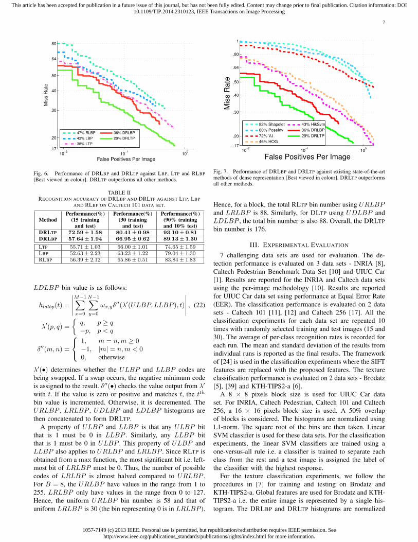
Fig. 6. Performance of DRLBP and DRLTP against LBP, LTP and RLBP[Best viewed in colour]. DRLTP outperforms all other methods.
TABLE IIRECOGNITION ACCURACY OF DRLBP AND DRLTP AGAINST LTP, LBP
AND RLBP ON CALTECH 101 DATA SET.
MethodPerformance(%) Performance(%) Performance(%)
(15 training (30 training (90% trainingand test) and test) and 10% test)
DRLTP 72.59± 1.58 80.41± 0.98 93.10± 0.81DRLBP 57.64± 1.94 66.95± 0.62 89.13± 1.30
LTP 55.71± 1.03 66.00± 1.01 74.65± 1.59LBP 52.63± 2.23 63.23± 1.22 79.04± 1.30RLBP 56.39± 2.12 65.86± 0.51 83.84± 1.83
LDLBP bin value is as follows:
hldlbp(t) =
∣∣∣∣∣M−1∑x=0
N−1∑y=0
ωx,yδ′′(λ′(ULBP,LLBP ), t)
∣∣∣∣∣ , (22)
λ′(p, q) =
{q, p ≥ q−p, p < q
δ′′(m,n) =
1, m = n,m ≥ 0−1, |m| = n,m < 00, otherwise
λ′(•) determines whether the ULBP and LLBP codes arebeing swapped. If a swap occurs, the negative minimum codeis assigned to the result. δ′′(•) checks the value output from λ′
with t. If the value is zero or positive and matches t, the tth
bin value is incremented. Otherwise, it is decremented. TheURLBP , LRLBP , UDLBP and LDLBP histograms arethen concatenated to form DRLTP.
A property of ULBP and LLBP is that any ULBP bitthat is 1 must be 0 in LLBP . Similarly, any LLBP bitthat is 1 must be 0 in ULBP . This property of ULBP andLLBP also applies to URLBP and LRLBP . Since RLTP isobtained from a max function, the most significant bit i.e. left-most bit of LRLBP must be 0. Thus, the number of possiblecodes of LRLBP is almost halved compared to URLBP .For B = 8, the URLBP have values in the range from 1 to255. LRLBP only have values in the range from 0 to 127.Hence, the uniform URLBP bin number is 58 and that ofuniform LRLBP is 30 (the bin representing 0 is in LRLBP ).
10−2
10−1
100
.17
.20
.30
.40
.50
.64
.80
1
False Positives Per Image
Mis
s R
ate
82% Shapelet
80% PoseInv
72% VJ
46% HOG
43% HikSvm
36% DRLBP
29% DRLTP
Fig. 7. Performance of DRLBP and DRLTP against existing state-of-the-artmethods of dense representation [Best viewed in colour]. DRLTP outperformsall other methods.
Hence, for a block, the total RLTP bin number using URLBPand LRLBP is 88. Similarly, for DLTP using UDLBP andLDLBP , the total bin number is also 88. Overall, the DRLTPbin number is 176.
III. EXPERIMENTAL EVALUATION
7 challenging data sets are used for evaluation. The de-tection performance is evaluated on 3 data sets - INRIA [8],Caltech Pedestrian Benchmark Data Set [10] and UIUC Car[1]. Results are reported for the INRIA and Caltech data setsusing the per-image methodology [10]. Results are reportedfor UIUC Car data set using performance at Equal Error Rate(EER). The classification performance is evaluated on 2 datasets - Caltech 101 [11], [12] and Caltech 256 [17]. All theclassification experiments for each data set are repeated 10times with randomly selected training and test images (15 and30). The average of per-class recognition rates is recorded foreach run. The mean and standard deviation of the results fromindividual runs is reported as the final results. The frameworkof [24] is used in the classification experiments where the SIFTfeatures are replaced with the proposed features. The textureclassification performance is evaluated on 2 data sets - Brodatz[5], [39] and KTH-TIPS2-a [6].
A 8 × 8 pixels block size is used for UIUC Car dataset. For INRIA, Caltech Pedestrian, Caltech 101 and Caltech256, a 16 × 16 pixels block size is used. A 50% overlapof blocks is considered. The histograms are normalized usingL1-norm. The square root of the bins are then taken. LinearSVM classifier is used for these data sets. For the classificationexperiments, the linear SVM classifiers are trained using aone-versus-all rule i.e. a classifier is trained to separate eachclass from the rest and a test image is assigned the label ofthe classifier with the highest response.
For the texture classification experiments, we follow theprocedures in [7] for training and testing on Brodatz andKTH-TIPS2-a. Global features are used for Brodatz and KTH-TIPS2-a i.e. the entire image is represented by a single his-togram. The DRLBP and DRLTP histograms are normalized

1057-7149 (c) 2013 IEEE. Personal use is permitted, but republication/redistribution requires IEEE permission. Seehttp://www.ieee.org/publications_standards/publications/rights/index.html for more information.
This article has been accepted for publication in a future issue of this journal, but has not been fully edited. Content may change prior to final publication. Citation information: DOI10.1109/TIP.2014.2310123, IEEE Transactions on Image Processing
8
first using L2-norm followed by L1-norm. Similar to [7], weuse a 3-nearest neighbor classifier with normalized histogramintersection as the distance measure between features.
For all data sets, a circular neighbourhood of radius 1 (R)and 8 (B) pixels is considered. The uniform pattern represen-tation is used. For LTP and DRLTP in our experiments, thethreshold, T , is 3 for INRIA and Caltech Pedestrian, 9 forUIUC Car, Caltech 101 and Caltech 256, 15 for Brodatz and5 for KTH-TIPS2-a.
A. Performance comparison of DRLBP and DRLTP againstLBP, LTP and RLBP
We compare the performance of DRLBP and DRLTPagainst LBP, LTP and RLBP on INRIA for detection and onCaltech 101 for classification. The INRIA training set contains2416 cropped positive images and 1218 uncropped negativeimages. The sliding image window size is 128 × 64 pixels.We randomly take 10 samples from each negative image toobtain a total of 12180 negative samples for training thelinear SVM classifier. Bootstrapping is then performed acrossmultiple scales at a scale step of 1.05 to obtain hard negativeswhich are added to the original training set for retraining. Thistraining procedure is exactly the same as described in [8], [10].
The INRIA test set consist of 288 images. The images arescanned over multiple scales at a scale step of 1.05. Thewindow stride is 8 pixels in the x and y directions. Theseparameters are the same as those in [10]. The miss rate (MR)against false positives per image (FPPI) (using log-log plots)is plotted to compare between different detectors. The log-average miss rate (LAMR) [10] is used to summarize thedetector performance which is computed by averaging the missrates at nine evenly spaced FPPI rates in the range 10−2 to 100.If any of the curves end before reaching 100, the minimummiss rate achieved is used [10].
From Fig. 6, it is seen that our proposed features outperformits predecessors. RLBP underperforms LBP as there is a lossof information due to the mapping of LBP codes and theircomplements to the same code. DRLBP outperforms RLBPand LBP. LTP outperforms LBP thanks to its robustness tonoise and small pixel value fluctuations. Similarly, DRLTPoutperforms LTP. Overall, DRLTP performs the best at 29%.
The two columns of Table II show the classification per-formances of DRLBP and DRLTP against LBP, LTP andRLBP on Caltech 101 using respective 15 and 30 trainingsamples per class where the number of test samples are upto the number of training samples for each class. Again, it isseen that our proposed features outperform its predecessors.DRLTP has a recognition rate of 72.59% while LTP has arecognition rate of 55.71% for the 15 training and test imagescase. This shows a significant gain of 17%. Furthermore, for30 training and test images case, the gain is 14%. Similarly,DRLBP has a gain of 1% and approximately 3% in comparisonto RLBP and LBP for both cases. Furthermore, we alsoperform another experiment using 90% of the samples perclass as training data with the remaining 10% as test data.The third column of the table shows the results. There is asignificant improvement in performance for all features. This
TABLE IIIRECOGNITION ACCURACY AT EQUAL ERROR RATE ON UIUC CARS DATASET. THE RESULTS OF HIKSVM FOR TEST SET II IS NOT PROVIDED IN [31].
Method Performance(%)Test Set I Test Set II
DRLTP 99.5 96.4DRLBP 98.3 88.5HIKSVM [31] 98.5 -Agarwal et al. [1] 79.0 45.0Mutch et al. [36] 99.9 90.6Hae et al. [49] 88.1 77.7Gall et al. [14] 98.5 98.6
is expected as there are more samples available for trainingwhich improves classification performance. DRLTP still givesthe best performance at 93.1%.
In the subsequent sections, only DRLBP and DRLTP willbe compared against some other state-of-the-art approaches.
B. Comparisons with other approaches on INRIA Data Set
We compare the DRLBP and DRLTP performance withVJ [55], SHAPELET [43], POSEINV [29], HIKSVM [31] andHOG [8]. The results of all compared detectors are given in[10]. These detectors are optimized, trained and tested in [10]by their respective authors. From Fig. 7, DRLTP achieves aLAMR of 29% which is significantly lower than all comparedstate-of-the-art methods. DRLBP has a LAMR of 36%.
C. Comparisons with other approaches on Caltech Data Set
The Caltech Pedestrian data set [10] contains color videosequences and pedestrians with a wide range of scales andscene variations. It has been created from a recorded video ona car moving through some densely populated human areas.It contains motion, blur and noise artifacts, and has variousstages of occlusion. The data set is divided into 11 sessions.The first 6 sessions are designated as the training set with theremaining 5 as the test set.
Results were reported in [10] using detectors trained onother data sets like INRIA for detection on their test set. Ourresults are also presented in a similar manner where detectorsare trained using the INRIA data set and tested on the testsessions. The scale step is 1.05. The window stride is 8 pixelsin the x and y directions. To detect humans at smaller scales,the original images are upscaled. Only every 30th frame isevaluated. The settings used are the same as [10].
The detectors compared with our implemented detectors arethe same as those in Section III-B. The results of the compareddetectors are given in [10]. These detectors are optimized,trained and tested in [10] by their respective authors. Theperformance is analyzed under six conditions [10] as shownin Fig. 8. The results are discussed under each condition asfollows.
Overall: Fig. 8(a) plots the performance on all test sessionsfor every annotated pedestrian. DRLBP and DRLTP rank firstat 86%. HOG is second at 90%. At lower FPPIs, DRLTPperforms better than DRLBP. For detection systems thatrequire low false positives with low MRs, DRLTP is preferred.

1057-7149 (c) 2013 IEEE. Personal use is permitted, but republication/redistribution requires IEEE permission. Seehttp://www.ieee.org/publications_standards/publications/rights/index.html for more information.
This article has been accepted for publication in a future issue of this journal, but has not been fully edited. Content may change prior to final publication. Citation information: DOI10.1109/TIP.2014.2310123, IEEE Transactions on Image Processing
9
10−3
10−2
10−1
100
.77
.80
.90
1
False Positives Per Image
Mis
s R
ate
100% VJ
97% Shapelet
96% PoseInv
91% HikSvm
90% HOG
86% DRLTP
86% DRLBP
10−3
10−2
10−1
100
.20
.30
.40
.50
.64
.80
1
False Positives Per Image
Mis
s R
ate
90% VJ
83% Shapelet
78% PoseInv
48% HikSvm
44% HOG
38% DRLBP
30% DRLTP
10−3
10−2
10−1
100
.72
.80
.90
1
False Positives Per Image
Mis
s R
ate
99% VJ
97% Shapelet
93% PoseInv
89% HikSvm
87% HOG
85% DRLTP
82% DRLBP
(a) Overall (b) Near Scale (c) Medium Scale
10−3
10−2
10−1
100
.40
.50
.64
.80
1
False Positives Per Image
Mis
s R
ate
94% VJ
91% Shapelet
86% PoseInv
72% HikSvm
66% HOG
60% DRLBP
56% DRLTP
10−3
10−2
10−1
100
.61
.70
.80
.90
1
False Positives Per Image
Mis
s R
ate
99% VJ
93% Shapelet
92% PoseInv
88% HikSvm
84% HOG
81% DRLBP
74% DRLTP
10−3
10−2
10−1
100
.42
.50
.64
.80
1
False Positives Per Image
Mis
s R
ate
95% VJ
91% Shapelet
86% PoseInv
73% HikSvm
68% HOG
62% DRLBP
58% DRLTP
(d) No Occlusion (e) Partial Occlusion (f) Reasonable
Fig. 8. Evaluation results under six different conditions on the test set of the Caltech Pedestrian Data Set [Best viewed in colour]. (a) DRLBP and DRLBPrank first in overall performance of all detectors on all annotated pedestrians. (b) DRLTP ranks first in performance on unoccluded pedestrians over 80 pixels(near scale). (c) DRLBP ranks first in performance on unoccluded pedestrians between 30-80 pixels. (d) DRLTP ranks first in performance on unoccludedpedestrians over 50 pixels tall. (e) Even under partial occlusion, DRLTP performs the best among all other methods. DRLBP ranks second. (f) DRLTP ranksfirst in performance on 50-pixel or taller, unoccluded or partially occluded pedestrians (reasonable).
Scale: Fig. 8(b) plots the performance on unoccluded pedes-trians with heights over 80 pixels. DRLTP performs the bestat 30% with DRLBP second at 38%. Fig. 8(c) plots theperformance on unoccluded pedestrians with heights between30 - 80 pixels. DRLBP ranks first at 82% followed by DRLTPat 85%. At lower FPPIs, DRLTP performs better than DRLBP.
Occlusion: Fig. 8(d) plots the performance on unoccludedpedestrians with heights over 50 pixels. DRLTP ranks firstat 56% and DRLBP ranks second at 60%. Fig. 8(e) plotsthe performance on partially occluded (1 - 35% occluded)pedestrians with heights over 50 pixels. DRLTP ranks firstat 74% and DRLBP ranks second at 81%.
Reasonable: Fig. 8(f) shows evaluation of performance onpedestrians that are over 50 pixels tall under no or partialocclusion (reasonable condition). DRLTP ranks first at 58%and DRLBP ranks second at 62%.
D. Comparisons with other approaches on UIUC Car
The data set contains side views of cars taken with cameras.The cars are of different resolutions and contain instances ofpartial occlusion, low contrast and highly noisy and texturedbackground. The training set contains 550 cars and 500 non-car images of 40 × 100 pixels.
There are 2 test sets. The first set contains 170 images with200 cars of the same size as those in the training set i.e. singlescale. The second set contains 108 images with 139 cars ofdifferent sizes ranging from 0.8 to 2 times the size of the cars
TABLE IVRECOGNITION ACCURACY ON CALTECH 101 DATA SET.
Approach Performance(%) Performance(%)(15 test) (30 test)
DRLTP 72.59± 1.58 80.41± 0.98DRLBP 57.64± 1.94 66.95± 0.62
Lazebnik et al. [24] 56.40 64.40± 0.80HIKSVM [31] 50.15± 0.61 56.49± 0.78Feature Context [57] 69.63± 0.84 77.09± 0.74Boiman et al. [4] 65.00± 1.14 70.04Gehler et al. [15] 70.00 77.70± 0.30Yang et al. [58] 67.00± 0.45 73.20± 0.54
in the training set i.e. multi scale. During testing, the windowstride is 5 pixels horizontally and 2 pixels vertically.
Table. III presents the DRLBP and DRLTP recognition ac-curacy at Equal Error Rate (EER) against some other methodsfor both test sets. In comparison with the other state-of-the-artmethods, DRLTP is second to [14] for multi scale test set andto [36] for the single scale test set. In [14], hybrid featureswith complex classification architecture is used. In [36], thefeatures are created from multiple convolutions with 8 filters (4Gabor and 4 3-D Max filters) over 10 scales. These are muchmore computationally intensive compared to our method andyet, we achieve a comparable performance.
E. Comparisons with other approaches on Caltech 101Caltech 101 contains 101 different object classes like an-
imals, vehicles, etc. with significant variance in shape and
1057-7149 (c) 2013 IEEE. Personal use is permitted, but republication/redistribution requires IEEE permission. Seehttp://www.ieee.org/publications_standards/publications/rights/index.html for more information.
This article has been accepted for publication in a future issue of this journal, but has not been fully edited. Content may change prior to final publication. Citation information: DOI10.1109/TIP.2014.2310123, IEEE Transactions on Image Processing
10
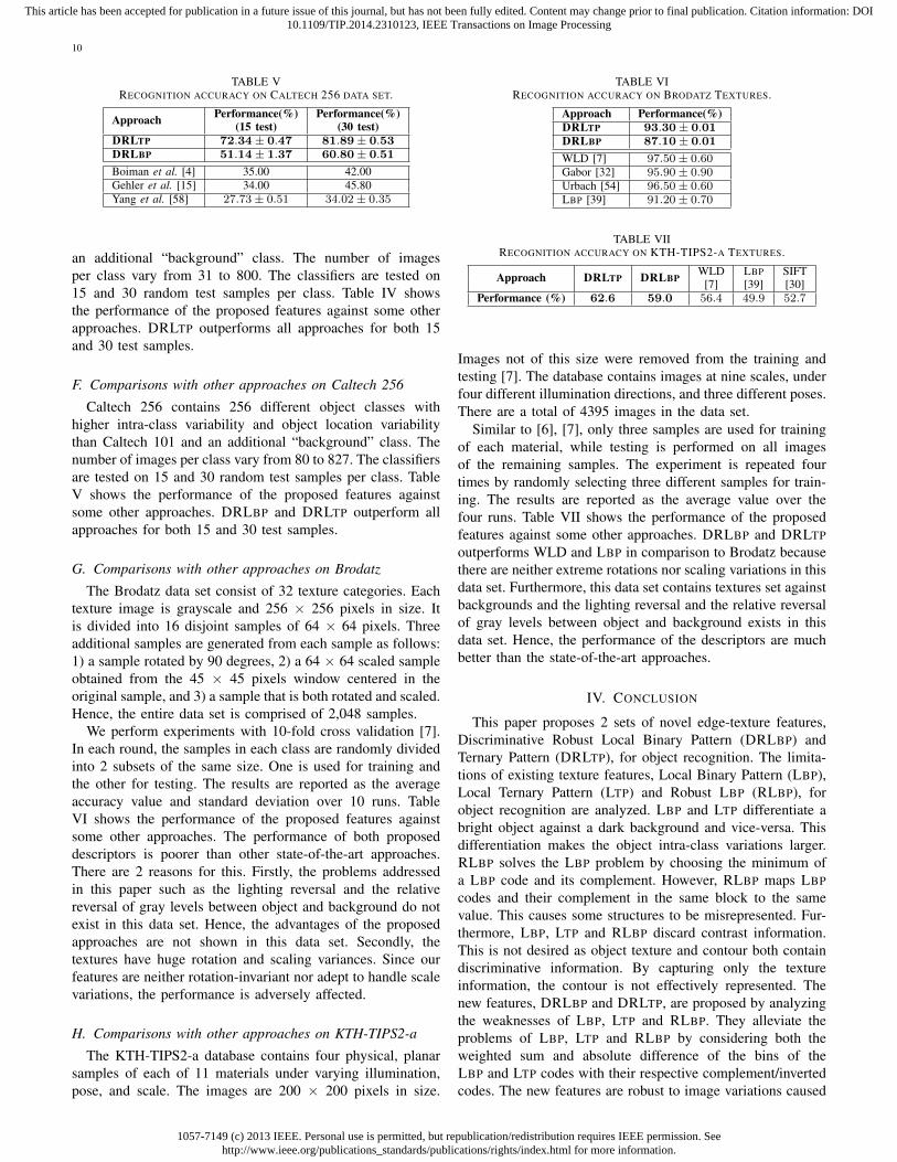
TABLE VRECOGNITION ACCURACY ON CALTECH 256 DATA SET.
Approach Performance(%) Performance(%)(15 test) (30 test)
DRLTP 72.34± 0.47 81.89± 0.53DRLBP 51.14± 1.37 60.80± 0.51
Boiman et al. [4] 35.00 42.00Gehler et al. [15] 34.00 45.80Yang et al. [58] 27.73± 0.51 34.02± 0.35
an additional “background” class. The number of imagesper class vary from 31 to 800. The classifiers are tested on15 and 30 random test samples per class. Table IV showsthe performance of the proposed features against some otherapproaches. DRLTP outperforms all approaches for both 15and 30 test samples.
F. Comparisons with other approaches on Caltech 256
Caltech 256 contains 256 different object classes withhigher intra-class variability and object location variabilitythan Caltech 101 and an additional “background” class. Thenumber of images per class vary from 80 to 827. The classifiersare tested on 15 and 30 random test samples per class. TableV shows the performance of the proposed features againstsome other approaches. DRLBP and DRLTP outperform allapproaches for both 15 and 30 test samples.
G. Comparisons with other approaches on Brodatz
The Brodatz data set consist of 32 texture categories. Eachtexture image is grayscale and 256 × 256 pixels in size. Itis divided into 16 disjoint samples of 64 × 64 pixels. Threeadditional samples are generated from each sample as follows:1) a sample rotated by 90 degrees, 2) a 64 × 64 scaled sampleobtained from the 45 × 45 pixels window centered in theoriginal sample, and 3) a sample that is both rotated and scaled.Hence, the entire data set is comprised of 2,048 samples.
We perform experiments with 10-fold cross validation [7].In each round, the samples in each class are randomly dividedinto 2 subsets of the same size. One is used for training andthe other for testing. The results are reported as the averageaccuracy value and standard deviation over 10 runs. TableVI shows the performance of the proposed features againstsome other approaches. The performance of both proposeddescriptors is poorer than other state-of-the-art approaches.There are 2 reasons for this. Firstly, the problems addressedin this paper such as the lighting reversal and the relativereversal of gray levels between object and background do notexist in this data set. Hence, the advantages of the proposedapproaches are not shown in this data set. Secondly, thetextures have huge rotation and scaling variances. Since ourfeatures are neither rotation-invariant nor adept to handle scalevariations, the performance is adversely affected.
H. Comparisons with other approaches on KTH-TIPS2-a
The KTH-TIPS2-a database contains four physical, planarsamples of each of 11 materials under varying illumination,pose, and scale. The images are 200 × 200 pixels in size.
TABLE VIRECOGNITION ACCURACY ON BRODATZ TEXTURES.
Approach Performance(%)DRLTP 93.30± 0.01DRLBP 87.10± 0.01
WLD [7] 97.50± 0.60Gabor [32] 95.90± 0.90Urbach [54] 96.50± 0.60LBP [39] 91.20± 0.70
TABLE VIIRECOGNITION ACCURACY ON KTH-TIPS2-A TEXTURES.
Approach DRLTP DRLBPWLD LBP SIFT
[7] [39] [30]Performance (%) 62.6 59.0 56.4 49.9 52.7
Images not of this size were removed from the training andtesting [7]. The database contains images at nine scales, underfour different illumination directions, and three different poses.There are a total of 4395 images in the data set.
Similar to [6], [7], only three samples are used for trainingof each material, while testing is performed on all imagesof the remaining samples. The experiment is repeated fourtimes by randomly selecting three different samples for train-ing. The results are reported as the average value over thefour runs. Table VII shows the performance of the proposedfeatures against some other approaches. DRLBP and DRLTPoutperforms WLD and LBP in comparison to Brodatz becausethere are neither extreme rotations nor scaling variations in thisdata set. Furthermore, this data set contains textures set againstbackgrounds and the lighting reversal and the relative reversalof gray levels between object and background exists in thisdata set. Hence, the performance of the descriptors are muchbetter than the state-of-the-art approaches.
IV. CONCLUSION
This paper proposes 2 sets of novel edge-texture features,Discriminative Robust Local Binary Pattern (DRLBP) andTernary Pattern (DRLTP), for object recognition. The limita-tions of existing texture features, Local Binary Pattern (LBP),Local Ternary Pattern (LTP) and Robust LBP (RLBP), forobject recognition are analyzed. LBP and LTP differentiate abright object against a dark background and vice-versa. Thisdifferentiation makes the object intra-class variations larger.RLBP solves the LBP problem by choosing the minimum ofa LBP code and its complement. However, RLBP maps LBPcodes and their complement in the same block to the samevalue. This causes some structures to be misrepresented. Fur-thermore, LBP, LTP and RLBP discard contrast information.This is not desired as object texture and contour both containdiscriminative information. By capturing only the textureinformation, the contour is not effectively represented. Thenew features, DRLBP and DRLTP, are proposed by analyzingthe weaknesses of LBP, LTP and RLBP. They alleviate theproblems of LBP, LTP and RLBP by considering both theweighted sum and absolute difference of the bins of theLBP and LTP codes with their respective complement/invertedcodes. The new features are robust to image variations caused

1057-7149 (c) 2013 IEEE. Personal use is permitted, but republication/redistribution requires IEEE permission. Seehttp://www.ieee.org/publications_standards/publications/rights/index.html for more information.
This article has been accepted for publication in a future issue of this journal, but has not been fully edited. Content may change prior to final publication. Citation information: DOI10.1109/TIP.2014.2310123, IEEE Transactions on Image Processing
11
by the intensity inversion and are discriminative to the imagestructures within the histogram block.
We present results of the proposed features on 7 data setsand compare them with several methods for object recognition.Results demonstrate that the proposed features outperform thecompared recognition approaches on most data sets.
REFERENCES
[1] S. Agarwal, A. Awan, and D. Roth, “Learning to detect objects in imagesvia a sparse, part-based representation,” IEEE Trans. Pattern Anal. Mach.Intell., vol. 26, no. 11, pp. 1475 –1490, Nov. 2004.
[2] T. Ahonen, A. Hadid, and M. Pietikainen, “Face description with localbinary patterns: Application to face recognition,” IEEE Trans. PatternAnal. Mach. Intell., vol. 28, no. 12, pp. 2037 – 2041, Dec. 2006.
[3] H. Bay, A. Ess, T. Tuytelaars, and L. J. V. Gool, “Speeded-up robustfeatures (surf),” Computer Vision and Image Understanding, vol. 110,no. 3, pp. 346–359, 2008.
[4] O. Boiman, E. Shechtman, and M. Irani, “In defense of nearest-neighborbased image classification,” in Proc. IEEE Int. Conf. Comput. Vis.Pattern Recognit., Jun. 2008, pp. 1–8.
[5] P. Brodatz, Textures: A Photographic Album for Artists and Designers.Dover Publications, Aug 1999.
[6] B. Caputo, E. Hayman, and P. Mallikarjuna, “Class-specific materialcategorisation,” in Proc. IEEE Int. Conf. Comput. Vis., vol. 2, 2005, pp.1597–1604 Vol. 2.
[7] J. Chen, S. Shan, C. He, G. Zhao, M. Pietikainen, X. Chen, and W. Gao,“Wld: A robust local image descriptor,” IEEE Trans. Pattern Anal. Mach.Intell., vol. 32, no. 9, pp. 1705–1720, 2010.
[8] N. Dalal and B. Triggs, “Histograms of oriented gradients for humandetection,” in Proc. IEEE Int. Conf. Comput. Vis. Pattern Recognit.,2005, pp. I: 886–893.
[9] H. Deng, W. Zhang, E. Mortensen, T. Dietterich, and L. Shapiro,“Principal curvature-based region detector for object recognition,” inProc. IEEE Int. Conf. Comput. Vis. Pattern Recognit., Jun. 2007, pp. 1–8.
[10] P. Dollar, C. Wojek, B. Schiele, and P. Perona, “Pedestrian detection:An evaluation of the state of the art,” IEEE Trans. Pattern Anal. Mach.Intell., vol. 34, no. 4, pp. 743 –761, Apr. 2012.
[11] L. Fei-fei, R. Fergus, and P. Perona, “One-shot learning of objectcategories,” IEEE Trans. Pattern Anal. Mach. Intell., vol. 28, no. 4,pp. 594 –611, Apr. 2006.
[12] R. Fergus, P. Perona, and A. Zisserman, “Object class recognition byunsupervised scale-invariant learning,” in Proc. IEEE Int. Conf. Comput.Vis. Pattern Recognit., vol. 2, Jun. 2003, pp. 264–271.
[13] A. Fernndez, M. lvarez, and F. Bianconi, “Texture description throughhistograms of equivalent patterns,” Journal of Mathematical Imagingand Vision, pp. 1–27, 2012.
[14] J. Gall and V. Lempitsky, “Class-specific hough forests for objectdetection,” in Proc. IEEE Int. Conf. Comput. Vis. Pattern Recognit.,Jun. 2009, pp. 1022 –1029.
[15] P. Gehler and S. Nowozin, “On feature combination for multiclass objectclassification,” in Proc. IEEE Int. Conf. Comput. Vis., Oct. 2009, pp. 221–228.
[16] C. Geng and X. Jiang, “Face recognition based on the multi-scale localimage structures,” Pattern Recognition, vol. 44, no. 10-11, pp. 2565 –2575, 2011.
[17] G. Griffin, A. Holub, and P. Perona, “Caltech-256 object categorydataset,” California Institute of Technology, Tech. Rep. 7694, 2007.[Online]. Available: http://authors.library.caltech.edu/7694
[18] Z. Guo, L. Zhang, and D. Zhang, “A completed modeling of local binarypattern operator for texture classification,” IEEE Trans. Image Process.,vol. 19, no. 6, pp. 1657 – 1663, Jun. 2010.
[19] A. Hadid, “The local binary pattern approach and its applications to faceanalysis,” in Image Processing Theory, Tools and Applications. FirstWorkshops on, Nov. 2008, pp. 1 – 9.
[20] C. He, T. Ahonen, and M. Pietikainen, “A bayesian local binary patterntexture descriptor,” in Proc. IEEE Int. Conf. Pattern Recognit., Dec.2008, pp. 1 –4.
[21] M. Heikkil, M. Pietikinen, and C. Schmid, “Description of interestregions with local binary patterns,” Pattern Recognition, vol. 42, no. 3,pp. 425 – 436, 2009.
[22] C. K. Heng, S. Yokomitsu, Y. Matsumoto, and H. Tamura, “Shrink boostfor selecting multi-lbp histogram features in object detection,” in Proc.IEEE Int. Conf. Comput. Vis. Pattern Recognit., Jun. 2012, pp. 3250–3257.
[23] S. Hussain and B. Triggs, “Visual recognition using local quantizedpatterns,” in Proc. Eur. Conf. Comput. Vis., ser. Lecture Notes inComputer Science. Springer Berlin Heidelberg, 2012, pp. 716–729.
[24] S. Lazebnik, C. Schmid, and J. Ponce, “Beyond bags of features: Spatialpyramid matching for recognizing natural scene categories,” in Proc.IEEE Int. Conf. Comput. Vis. Pattern Recognit., vol. 2, 2006, pp. 2169–2178.
[25] K. Levi and Y. Weiss, “Learning object detection from a small numberof examples: the importance of good features,” in Proc. IEEE Int. Conf.Comput. Vis. Pattern Recognit., vol. 2, Jun. 2004, pp. 53 – 60.
[26] S. Li, R. Chu, S. Liao, and L. Zhang, “Illumination invariant facerecognition using near-infrared images,” IEEE Trans. Pattern Anal.Mach. Intell., vol. 29, no. 4, pp. 627 – 639, Apr. 2007.
[27] S. Liao, M. Law, and A. Chung, “Dominant local binary patterns fortexture classification,” IEEE Trans. Image Process., vol. 18, no. 5, pp.1107 – 1118, May 2009.
[28] S. Liao, G. Zhao, V. Kellokumpu, M. Pietika andinen, and S. Li, “Mod-eling pixel process with scale invariant local patterns for backgroundsubtraction in complex scenes,” in Proc. IEEE Int. Conf. Comput. Vis.Pattern Recognit., Jun. 2010, pp. 1301 –1306.
[29] Z. Lin and L. Davis, “Shape-based human detection and segmentationvia hierarchical part-template matching,” IEEE Trans. Pattern Anal.Mach. Intell., vol. 32, no. 4, pp. 604 –618, Apr. 2010.
[30] D. Lowe, “Distinctive image features from scale-invariant keypoints,”Int. J. Comput. Vis., vol. 60, no. 2, pp. 91–110, Nov. 2004.
[31] S. Maji, A. C. Berg, and J. Malik, “Efficient classification for additivekernel svms,” IEEE Trans. Pattern Anal. Mach. Intell., vol. 35, no. 1,pp. 66 –77, Jan. 2013.
[32] B. Manjunath and W. Ma, “Texture features for browsing and retrievalof image data,” IEEE Trans. Pattern Anal. Mach. Intell., vol. 18, no. 8,pp. 837–842, 1996.
[33] J. Maver, “Self-similarity and points of interest,” IEEE Trans. PatternAnal. Mach. Intell., vol. 32, no. 7, pp. 1211 –1226, Jul. 2010.
[34] Z. Miao and X. Jiang, “Interest point detection using rank order logfilter,” Pattern Recognition, vol. 46, no. 11, pp. 2890 – 2901, 2013.
[35] K. Mikolajczyk and C. Schmid, “A performance evaluation of localdescriptors,” IEEE Trans. Pattern Anal. Mach. Intell., vol. 27, no. 10,pp. 1615 –1630, Oct. 2005.
[36] J. Mutch and D. Lowe, “Multiclass object recognition with sparse,localized features,” in Proc. IEEE Int. Conf. Comput. Vis. PatternRecognit., vol. 1, Jun. 2006, pp. 11 – 18.
[37] D. T. Nguyen, Z. Zong, P. Ogunbona, and W. Li, “Object detection usingnon-redundant local binary patterns,” in Proc. IEEE Int. Conf. Image.Process., Sep. 2010, pp. 4609 –4612.
[38] T. Ojala, M. Pietikainen, and T. Maenpaa, “Multiresolution gray-scaleand rotation invariant texture classification with local binary patterns,”IEEE Trans. Pattern Anal. Mach. Intell., vol. 24, no. 7, pp. 971 –987,Jul. 2002.
[39] T. Ojala, K. Valkealahti, E. Oja, and M. Pietikinen, “Texture dis-crimination with multidimensional distributions of signed gray-leveldifferences,” Pattern Recognition, vol. 34, no. 3, pp. 727 – 739, 2001.
[40] C. Papageorgiou and T. Poggio, “A trainable system for object detec-tion,” Int. J. Comput. Vis., vol. 38, no. 1, pp. 15–33, Jun. 2000.
[41] A. Porebski, N. Vandenbroucke, and L. Macaire, “Haralick featureextraction from LBP images for color texture classification,” in ImageProcessing Theory, Tools and Applications. First Workshops on, Nov.2008, pp. 1 – 8.
[42] J. Ren, X. Jiang, and J. Yuan, “Noise-resistant local binary pattern withan embedded error-correction mechanism,” IEEE Trans. Image Process.,vol. 22, no. 10, pp. 4049–4060, 2013.
[43] P. Sabzmeydani and G. Mori, “Detecting pedestrians by learning shapeletfeatures,” in Proc. IEEE Int. Conf. Comput. Vis. Pattern Recognit., Jun.2007, pp. 1 –8.
[44] A. Satpathy, X. Jiang, and H.-L. Eng, “Human detection by quadraticclassification on subspace of extended histogram of gradients,” IEEETrans. Image Process., vol. 23, no. 1, pp. 287–297, 2014.
[45] A. Satpathy, X. Jiang, and H.-L. Eng, “Extended histogram of gradientsfeature for human detection,” in Proc. IEEE Int. Conf. Image. Process.,Sep. 2010, pp. 3473 –3476.
[46] A. Satpathy, X. Jiang, and H.-L. Eng, “Extended histogram of gradientswith asymmetric principal component and discriminant analyses forhuman detection,” in Proc. IEEE Canad. Conf. Comput. Robot. Vis.,May 2011, pp. 64 –71.

1057-7149 (c) 2013 IEEE. Personal use is permitted, but republication/redistribution requires IEEE permission. Seehttp://www.ieee.org/publications_standards/publications/rights/index.html for more information.
This article has been accepted for publication in a future issue of this journal, but has not been fully edited. Content may change prior to final publication. Citation information: DOI10.1109/TIP.2014.2310123, IEEE Transactions on Image Processing
12
[47] A. Satpathy, X. Jiang, and H.-L. Eng, “Human detection using discrim-inative and robust local binary pattern,” in Proc. IEEE Int. Conf. Acous.Speech. Sig. Process., May 2013, pp. 2376 – 2380.
[48] A. Satpathy, X. Jiang, and H.-L. Eng, “Visual object detection by parts-based modeling using extended histogram of gradients,” in Proc. IEEEInt. Conf. Image. Process., Sept 2013, pp. 2738 – 2742.
[49] H. J. Seo and P. Milanfar, “Training-free, generic object detection usinglocally adaptive regression kernels,” IEEE Trans. Pattern Anal. Mach.Intell., vol. 32, no. 9, pp. 1688 –1704, Sep. 2010.
[50] E. Shechtman and M. Irani, “Matching local self-similarities acrossimages and videos,” in Proc. IEEE Int. Conf. Comput. Vis. PatternRecognit., Jun. 2007, pp. 1–8.
[51] J. Stottinger, A. Hanbury, N. Sebe, and T. Gevers, “Sparse color interestpoints for image retrieval and object categorization,” IEEE Trans. ImageProcess., vol. 21, no. 5, pp. 2681 –2692, May 2012.
[52] X. Tan and B. Triggs, “Enhanced local texture feature sets for facerecognition under difficult lighting conditions,” IEEE Trans. ImageProcess., vol. 19, no. 6, pp. 1635 –1650, Jun. 2010.
[53] T. Tuytelaars and C. Schmid, “Vector quantizing feature space with aregular lattice,” in Proc. IEEE Int. Conf. Comput. Vis., Oct. 2007, pp. 1–8.
[54] E. Urbach, J. B. T. M. Roerdink, and M. H. F. Wilkinson, “Connectedshape-size pattern spectra for rotation and scale-invariant classificationof gray-scale images,” IEEE Trans. Pattern Anal. Mach. Intell., vol. 29,no. 2, pp. 272–285, 2007.
[55] P. Viola, M. J. Jones, and D. Snow, “Detecting pedestrians using patternsof motion and appearance,” Int. J. Comput. Vis., vol. 63, no. 2, pp. 153–161, 2005.
[56] J. Wang, J. Yang, K. Yu, F. Lv, T. Huang, and Y. Gong, “Locality-constrained linear coding for image classification,” in Proc. IEEE Int.Conf. Comput. Vis. Pattern Recognit., Jun. 2010, pp. 3360 –3367.
[57] X. Wang, X. Bai, W. Liu, and L. Latecki, “Feature context for imageclassification and object detection,” in Proc. IEEE Int. Conf. Comput.Vis. Pattern Recognit., Jun. 2011, pp. 961 –968.
[58] J. Yang, K. Yu, Y. Gong, and T. Huang, “Linear spatial pyramidmatching using sparse coding for image classification,” in Proc. IEEEInt. Conf. Comput. Vis. Pattern Recognit., Jun. 2009, pp. 1794 –1801.
[59] H. Zhang, A. Berg, M. Maire, and J. Malik, “Svm-knn: Discriminativenearest neighbor classification for visual category recognition,” in Proc.IEEE Int. Conf. Comput. Vis. Pattern Recognit., vol. 2, 2006, pp. 2126–2136.
[60] J. Zhang, J. Liang, and H. Zhao, “Local energy pattern for textureclassification using self-adaptive quantization thresholds,” IEEE Trans.Image Process., vol. PP, no. 99, p. 1, 2012.
[61] W. Zhang, S. Shan, X. Chen, and W. Gao, “Local gabor binarypatterns based on kullback-leibler divergence for partially occluded facerecognition,” IEEE Signal Process. Lett., vol. 14, no. 11, pp. 875 – 878,Nov. 2007.
[62] G. Zhao and M. Pietikainen, “Dynamic texture recognition using localbinary patterns with an application to facial expressions,” IEEE Trans.Pattern Anal. Mach. Intell., vol. 29, no. 6, pp. 915 – 928, Jun. 2007.
Amit Satpathy received his B.Eng. and Ph.D. de-grees both in Electrical and Electronic Engineeringfrom Nanyang Technological University, Singapore,in 2007 and 2014, respectively. He is the recipientof the A*STAR Graduate Scholarship. His currentresearch focuses on feature development and ex-traction for object detection and recognition, im-age/video processing, pattern recognition, computervision and machine learning. Currently, he is withthe Programme Director’s Office in Institute for In-focomm Research, Agency for Science, Technology
and Research, Singapore as a Scientist.
Xudong Jiang (M’02-SM’06) received the B.Eng.and M.Eng. degrees from the University of Elec-tronic Science and Technology of China (UESTC),Chengdu, China, in 1983 and 1986, respectively, andthe Ph.D. degree from Helmut Schmidt University,Hamburg, Germany, in 1997, all in electrical en-gineering. From 1986 to 1993, he was a Lecturerwith UESTC, where he received two Science andTechnology Awards from the Ministry for ElectronicIndustry of China. From 1993 to 1997, he was aScientific Assistant with Helmut Schmidt University.
From 1998 to 2004, he was with the Institute for Infocomm Research,Agency for Science, Technology and Research, Singapore, as a Lead Scientistand the Head of the Biometrics Laboratory, where he developed a systemthat achieved the most efficiency and the second most accuracy at theInternational Fingerprint Verification Competition in 2000. He joined NanyangTechnological University, Singapore, as a Faculty Member, in 2004, andserved as the Director of the Centre for Information Security from 2005 to2011. Currently, he is a Tenured Associate Professor with the School of EEE,NTU. He has published over 100 papers, where 17 papers in IEEE Journals:TIP (5), TPAMI (4), TSP (3), SPM, TIFS, TCSVT, TCS-II, and SPL. He holdsseven patents. His current research interests include signal/image processing,pattern recognition, computer vision, machine learning, and biometrics.
Biodata:
How-Lung Eng (M'03) received his BEng and PhD degrees both in Electrical and Electronic Engineering from Nanyang Technological University, Singapore, in 1998 and 2002, respectively. Currently, he is with the Institute for Infocomm Research, Singapore as a research scientist and Programme Manager of Video Behavioral Analytics Programme. His research interest includes real-time vision, pattern classification and machine learning for abnormal event detection. He has made several PCT fillings related to video surveillance applications and has actively published his works in the above areas of interest. He was a recipient of the Tan Kah Kee Young Inventors' Award 2000 (Silver, Open Section) for his PhD study, and a recipient of the TEC Innovator Award 2002, the IES Prestigious Engineering Awards 2006 and 2008 and IWA PIA Asia Pacific Regional
Award 2012 for his works in the areas of video surveillance and video monitoring to ensure safe drinking water.
Contact: How-Lung Eng Research Scientist Programme Manager Institute for Infocomm Research 1 Fusionopolis Way #21-01 Connexis (South Tower) Singapore 138632 Tel: +65 6408 2501 Fax: +65 6776 1378 Email: [email protected], [email protected]
How-Lung Eng (M’03) received his B.Eng. andPh.D. degrees both in Electrical and Electronic En-gineering from Nanyang Technological University,Singapore, in 1998 and 2002, respectively. He iscurrently CTO of Zweec Analytics, a Singaporehomegrown technology company spun out from theInstitute for Infocomm Research (I2R). Prior to this,he was with the Institute for Infocomm Researchas a research scientist and Programme Managerfor Video Behavioral Analytics Programme. Hisresearch interest includes real-time vision, pattern
classification and machine learning for abnormal event detection. He has madeseveral PCT fillings related to video surveillance applications and has activelypublished his works in the above areas of interest. He was a recipient ofthe Tan Kah Kee Young Inventors’ Award 2000 (Silver, Open Section) forhis PhD study, and a recipient of the TEC Innovator Award 2002, the IESPrestigious Engineering Awards 2006 and 2008 and IWA PIA Asia PacificRegional Award 2012 for his works in the areas of video surveillance andvideo analytic to ensure safe drinking water.