lcd tv tanzanite training manual€¦ · lcd tv advantage Ⅰ.understanding of lcd tv high...
TRANSCRIPT
LCD TV
Tanzanite
TRAINING MANUAL
AgendaAgenda
I. Understanding of LCD TV
II. Inside of Tanzanite Model
III. Board description
IV. Disassembly
V. Trouble Shooting
VI. How to Upgrade
VII. Attachment.

Ⅰ. Understanding of LCD TV
UNDERSTANDINGOF LCD TV
Ⅰ. Understanding of LCD TV
CONTENTSCONTENTS
I. LCD TV advantage
II. Basic theory of LCD PANEL
III. Basic block of LCD TV
IV. Basic block of main PBA
V. What is scaler?
VI. TV signal types
VII. TV connector types
LCD TV Advantage
Ⅰ. Understanding of LCD TV
High Sharpness, Resolution
Thin and Light ( 40 Inch is 5cm thickness )
Low Power Consumption
Real HDTV
Long Life
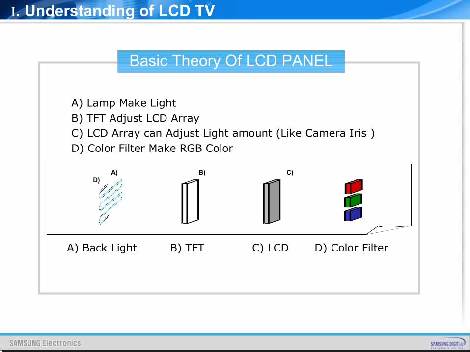
Basic Theory Of LCD PANEL
Ⅰ. Understanding of LCD TV
A) B) C) D)
A) Back Light B) TFT C) LCD D) Color Filter
A) Lamp Make LightB) TFT Adjust LCD ArrayC) LCD Array can Adjust Light amount (Like Camera Iris )D) Color Filter Make RGB Color
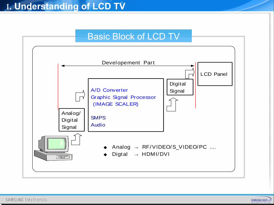
Basic Block of LCD TV
Ⅰ. Understanding of LCD TV
Analog/
Digital
Signal
Digital
Signal
Developement Par t
A/D Converter
Graphic Signal Processor
(IMAGE SCALER)
SMPS
Audio
LCD Panel
◆ Analog → RF/VIDEO/S_VIDEO/PC ....◆ Digtal → HDMI/DVI
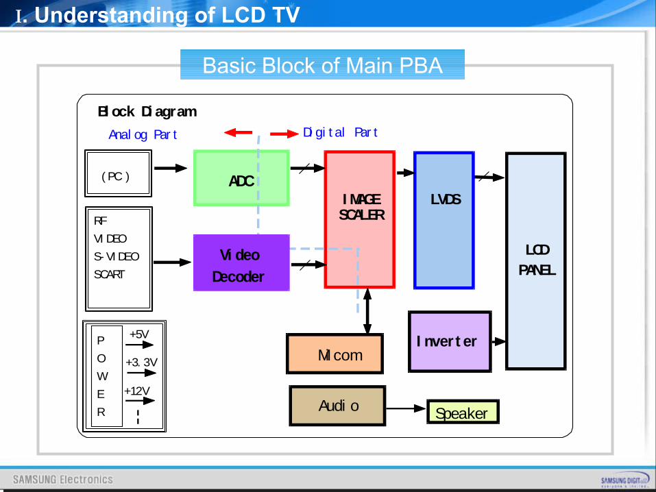
Basic Block of Main PBA
Ⅰ. Understanding of LCD TV
Bl ock Di agram
( PC )
P
O
W
E
R
LCDPANEL
+5V
+12V
ADCI MAGESCALER
Mi com
Anal og Par t Di gi t al Par t
RF
VI DEO
S- VI DEO
SCART
+3. 3V
LVDS
I nver t er
Audi o Speaker
ADCVi deo
Decoder
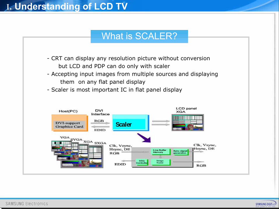
What is SCALER?
Ⅰ. Understanding of LCD TV
- CRT can display any resolution picture without conversion but LCD and PDP can do only with scaler- Accepting input images from multiple sources and displaying them on any flat panel display- Scaler is most important IC in flat panel display
Scaler
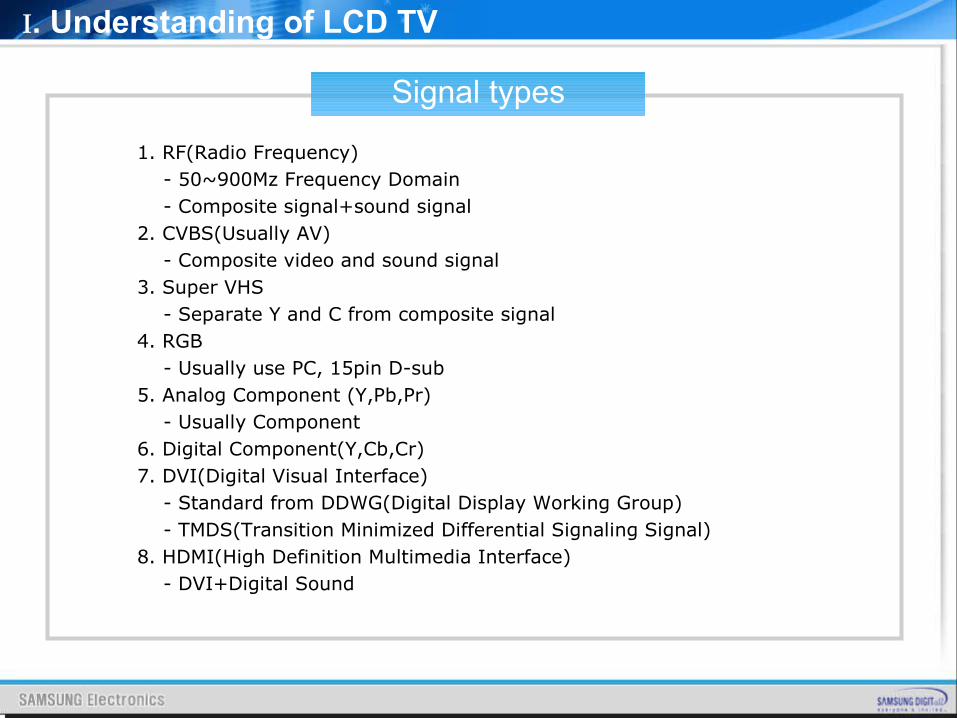
1. RF(Radio Frequency) - 50~900Mz Frequency Domain - Composite signal+sound signal2. CVBS(Usually AV) - Composite video and sound signal3. Super VHS - Separate Y and C from composite signal4. RGB - Usually use PC, 15pin D-sub 5. Analog Component (Y,Pb,Pr) - Usually Component6. Digital Component(Y,Cb,Cr)7. DVI(Digital Visual Interface) - Standard from DDWG(Digital Display Working Group) - TMDS(Transition Minimized Differential Signaling Signal) 8. HDMI(High Definition Multimedia Interface) - DVI+Digital Sound
Signal types
Ⅰ. Understanding of LCD TV
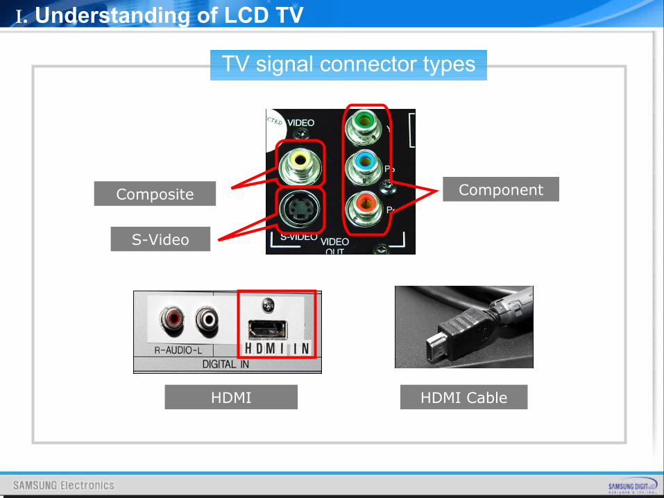
TV signal connector types
Ⅰ. Understanding of LCD TV
Composite
S-Video
Component
HDMI HDMI Cable
Ⅱ. Inside of Tanzanite Model
Inside of Tanzanite Model
CONTENTSCONTENTS
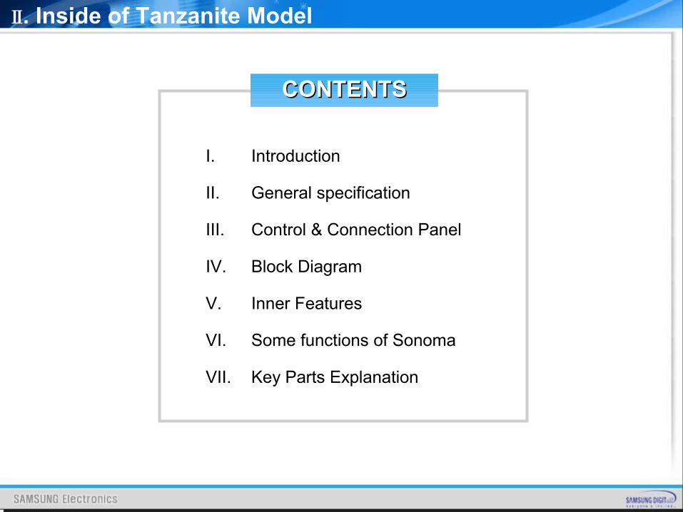
I. Introduction
II. General specification
III. Control & Connection Panel
IV. Block Diagram
V. Inner Features
VI. Some functions of Sonoma
VII. Key Parts Explanation
Ⅱ. Inside of Tanzanite Model
IntroductionIntroduction
Best Picture Quality
Simple Function, New Design
Acceptable Price
Support HDMI
Some Functions
Ⅱ. Inside of Tanzanite Model
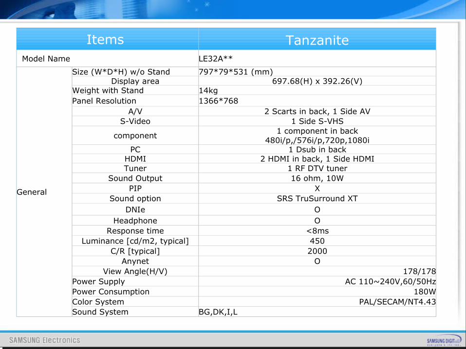
Items Tanzanite Model Name LE32A**
General
Size (W*D*H) w/o Stand 797*79*531 (mm) Display area 697.68(H) x 392.26(V)
Weight with Stand 14kg Panel Resolution 1366*768
A/V 2 Scarts in back, 1 Side AVS-Video 1 Side S-VHS
component 1 component in back480i/p,/576i/p,720p,1080i
PC 1 Dsub in backHDMI 2 HDMI in back, 1 Side HDMITuner 1 RF DTV tuner
Sound Output 16 ohm, 10WPIP X
Sound option SRS TruSurround XTDNIe O
Headphone OResponse time <8ms
Luminance [cd/m2, typical] 450C/R [typical] 2000
Anynet OView Angle(H/V) 178/178
Power Supply AC 110~240V,60/50HzPower Consumption 180WColor System PAL/SECAM/NT4.43Sound System BG,DK,I,L
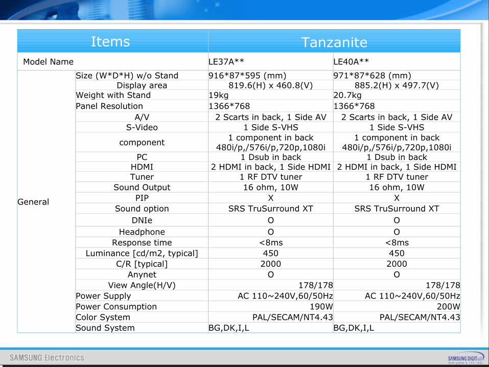
Items Tanzanite Model Name LE37A** LE40A**
General
Size (W*D*H) w/o Stand 916*87*595 (mm) 971*87*628 (mm) Display area 819.6(H) x 460.8(V) 885.2(H) x 497.7(V)
Weight with Stand 19kg 20.7kg Panel Resolution 1366*768 1366*768
A/V 2 Scarts in back, 1 Side AV 2 Scarts in back, 1 Side AVS-Video 1 Side S-VHS 1 Side S-VHS
component 1 component in back480i/p,/576i/p,720p,1080i
1 component in back480i/p,/576i/p,720p,1080i
PC 1 Dsub in back 1 Dsub in backHDMI 2 HDMI in back, 1 Side HDMI 2 HDMI in back, 1 Side HDMITuner 1 RF DTV tuner 1 RF DTV tuner
Sound Output 16 ohm, 10W 16 ohm, 10WPIP X X
Sound option SRS TruSurround XT SRS TruSurround XTDNIe O O
Headphone O OResponse time <8ms <8ms
Luminance [cd/m2, typical] 450 450C/R [typical] 2000 2000
Anynet O OView Angle(H/V) 178/178 178/178
Power Supply AC 110~240V,60/50Hz AC 110~240V,60/50HzPower Consumption 190W 200WColor System PAL/SECAM/NT4.43 PAL/SECAM/NT4.43Sound System BG,DK,I,L BG,DK,I,L
Ⅱ. Inside of Tanzanite Model
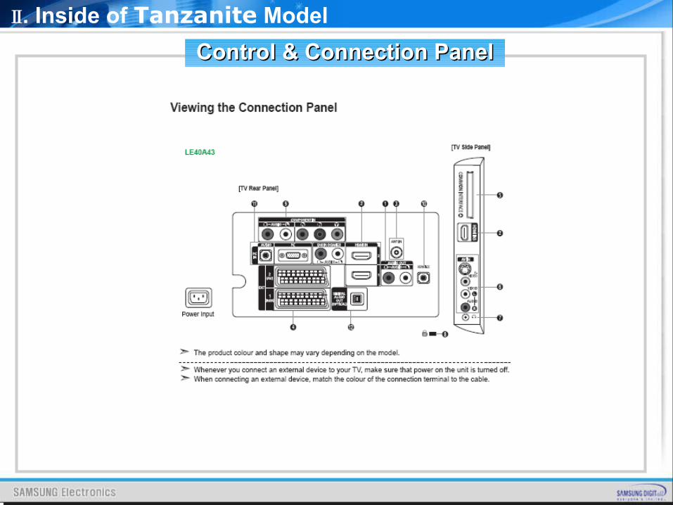
Control & Connection PanelControl & Connection Panel
Control & Connection PanelControl & Connection Panel
Ⅱ. Inside of Tanzanite Model
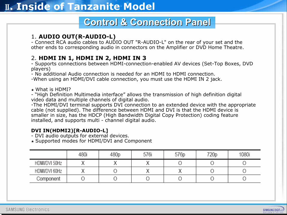
1. AUDIO OUT(R-AUDIO-L)- Connect RCA audio cables to AUDIO OUT "R-AUDIO-L" on the rear of your set and the other ends to corresponding audio in connectors on the Amplifier or DVD Home Theatre.
2. HDMI IN 1, HDMI IN 2, HDMI IN 3- Supports connections between HDMI-connection-enabled AV devices (Set-Top Boxes, DVD players)- No additional Audio connection is needed for an HDMI to HDMI connection.-When using an HDMI/DVI cable connection, you must use the HDMI IN 2 jack.
★ What is HDMI?- “High Definition Multimedia interface” allows the transmission of high definition digital video data and multiple channels of digital audio.-The HDMI/DVI terminal supports DVI connection to an extended device with the appropriate cable (not supplied). The difference between HDMI and DVI is that the HDMI device is smaller in size, has the HDCP (High Bandwidth Digital Copy Protection) coding feature installed, and supports multi - channel digital audio.
DVI IN(HDMI2)[R-AUDIO-L]- DVI audio outputs for external devices.
★ Supported modes for HDMI/DVI and Component
Control & Connection PanelControl & Connection Panel
Ⅱ. Inside of Tanzanite Model
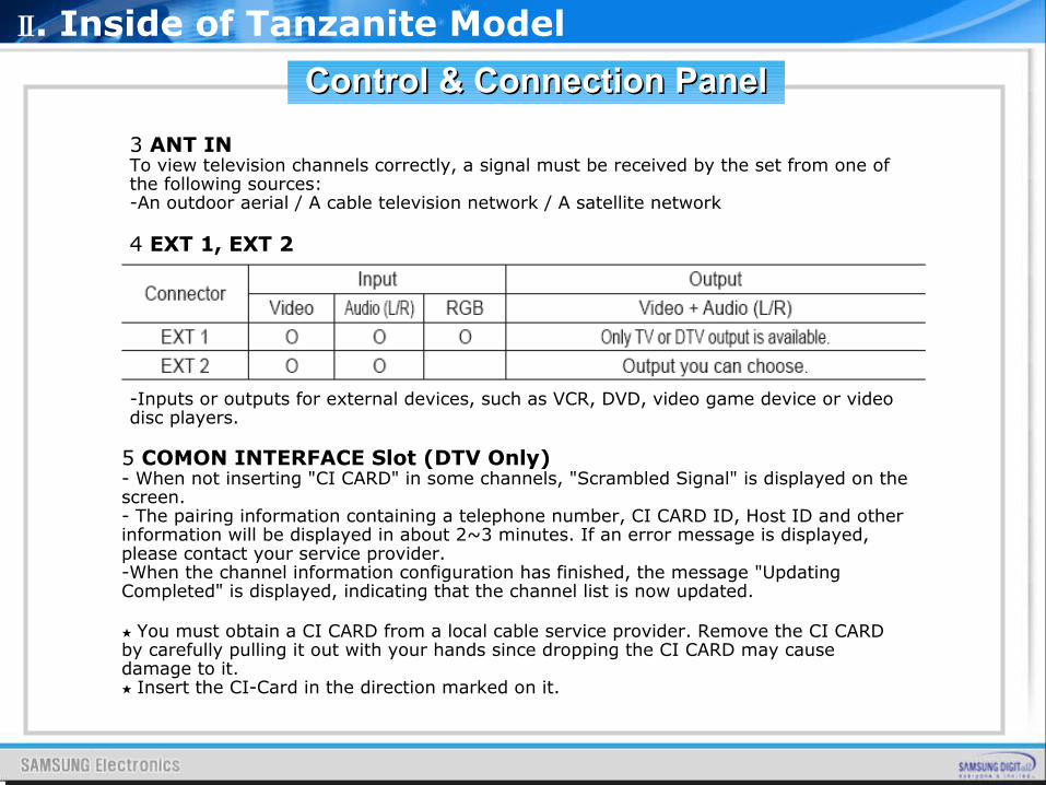
3 ANT INTo view television channels correctly, a signal must be received by the set from one of the following sources:-An outdoor aerial / A cable television network / A satellite network
4 EXT 1, EXT 2
-Inputs or outputs for external devices, such as VCR, DVD, video game device or video disc players.
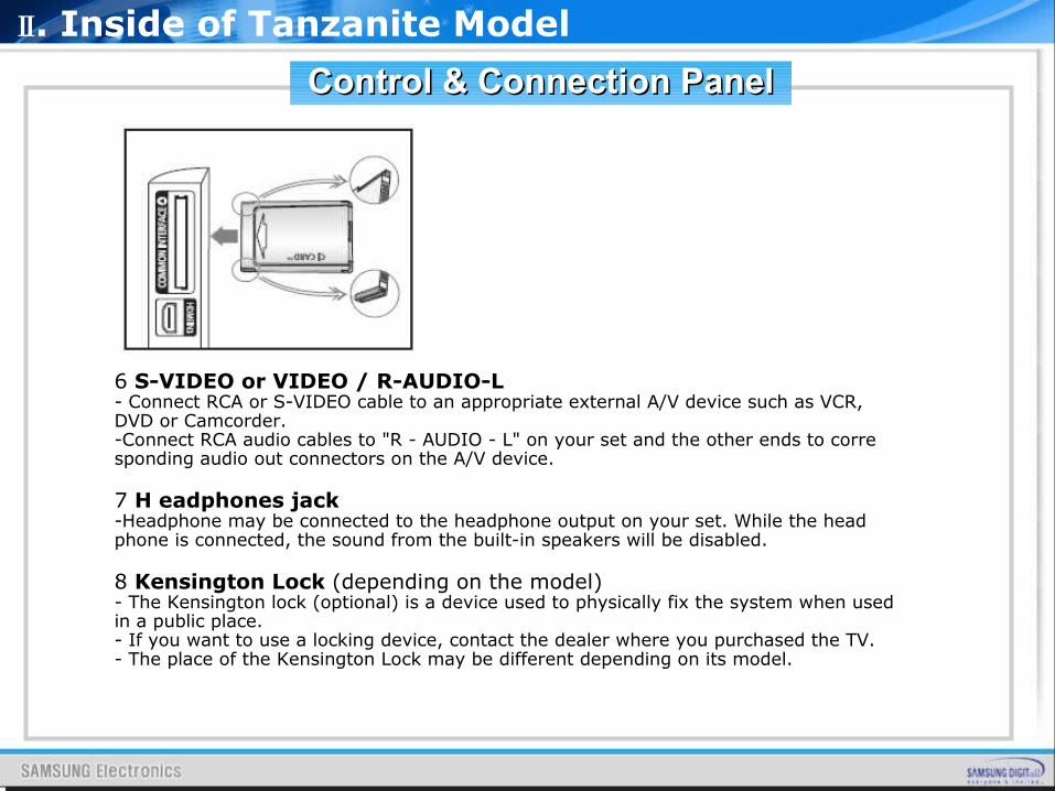
5 COMON INTERFACE Slot (DTV Only)- When not inserting "CI CARD" in some channels, "Scrambled Signal" is displayed on the screen.- The pairing information containing a telephone number, CI CARD ID, Host ID and other information will be displayed in about 2~3 minutes. If an error message is displayed, please contact your service provider.-When the channel information configuration has finished, the message "Updating Completed" is displayed, indicating that the channel list is now updated.
★ You must obtain a CI CARD from a local cable service provider. Remove the CI CARD by carefully pulling it out with your hands since dropping the CI CARD may cause damage to it.
★ Insert the CI-Card in the direction marked on it.
Control & Connection PanelControl & Connection Panel
Ⅱ. Inside of Tanzanite Model
6 S-VIDEO or VIDEO / R-AUDIO-L- Connect RCA or S-VIDEO cable to an appropriate external A/V device such as VCR, DVD or Camcorder.-Connect RCA audio cables to "R - AUDIO - L" on your set and the other ends to corre sponding audio out connectors on the A/V device.
7 H eadphones jack-Headphone may be connected to the headphone output on your set. While the head phone is connected, the sound from the built-in speakers will be disabled.
8 Kensington Lock (depending on the model)- The Kensington lock (optional) is a device used to physically fix the system when used in a public place.- If you want to use a locking device, contact the dealer where you purchased the TV.- The place of the Kensington Lock may be different depending on its model.
Control & Connection PanelControl & Connection Panel
Ⅱ. Inside of Tanzanite Model
9 COMPONENT IN- Connect component video cables (optional) to component connector ("PR", "PB", "Y") on the rear of your set and the other ends to corresponding component video out connectors on the DTV or DVD.- If you wish to connect both the Set-Top Box and DTV (or DVD), you should connect the Set-Top Box to the DTV (or DVD) and connect the DTV (or DVD) to component connector ("PR", "PB", "Y") on your set.- The PR, PB and Y connectors on your component devices (DTV or DVD) are sometimes labeled Y, B-Y and R-Y or Y, Cb and Cr.- Connect RCA audio cables (optional) to "R - AUDIO - L" on the rear of your set and the other ends to corresponding audio out connectors on the DTV or DVD.
10 SERVICE-Connector for SERVICE only.
11 PC IN [PC] / [AUDIO]-Connect to the video and audio output jack on your PC.
12 DIGITAL AUDIO OUT (OPTICAL) DTV Only- Connect to a Digital Audio Component.
★ When the HDMI IN jacks are connected, the DIGITAL AUDIO OUT (OPTICAL) jack on the TV outputs 2 channel audio only. If you want to hear 5.1 channel audio, connect the Optical jack on the DVD player or Cable/Satellite Box directly to an Amplifier or Home Theater, not the TV.
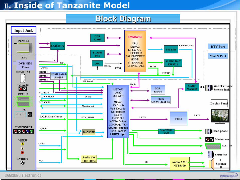
Block DiagramBlock Diagram
Ⅱ. Inside of Tanzanite Model
VIDEO AUDIO BUS I2C NORMAL SIGNAL
HDMI 1,2,3
DVI Audio
COMPONENT
Audio AMPNTP3100
LSpeaker
R
S-VIDEO
DDR 8M*16
LVDS
ANT
DVB NIM Tuner
PC
Input Jack
Display Panel
MSTARLola2
(256-QFP)
Micom3D Comb
Multi DecoderDe-iterlacer
ScalerLVDS Out
WXGA Output1000Page TTX
Sound Process10bit Process2 HDMI input
Monitor out
SPDIF out
EMMA2SL
CPUIDEMUX
MPEG A/V-DECODER
PAL ENCODERHOST-
INTERFACEPERIPHERALS
PCMCIA
TS
FLASH4MB
DDR32MB
OSC27MHz
PWM
UARTMAX232
FILTER
AUDIO DACEW8521
R,G,B,Hsync,Vsync
Y,Pb,Pr
Y,C
CVBS
EXT 1/2SC1:CVBS,FB
SC2:CVBS
DTV R/L
SIF
SPDIF
Y,Pb,Pr,CVBS
Rx,Tx
I2S
DTV Part
MAIN Part
SC1:RGB
VIDEO CVBS
BA7657F
Audio SW74HC4052
I2S Sound
FlashMX25L,16M Bit
EXT1_out
Monitor out
HDMI 2
HDMI 1
FBE3LVDS
Head phone
DTV_SPDIF
Main/DTV/LogicService Jack
TV out
HDMI SwitchSii9185
HDMI 3
Max9728AAMP
CX16244*2

SMPS, Main Board, Panel
Inner Feature of 32”Inner Feature of 32”
Ⅱ. Inside of Tanzanite Model
SPEAKER SPEAKER
MAIN B’DSMPS
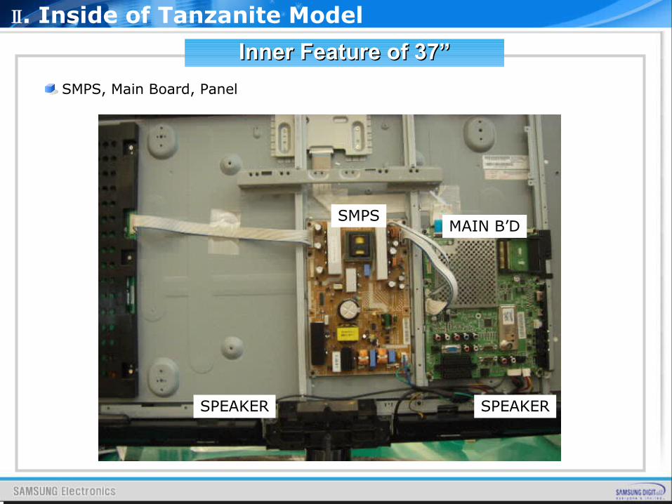
SMPS, Main Board, Panel
Inner Feature of 37”Inner Feature of 37”
Ⅱ. Inside of Tanzanite Model
SPEAKER SPEAKER
MAIN B’DSMPS
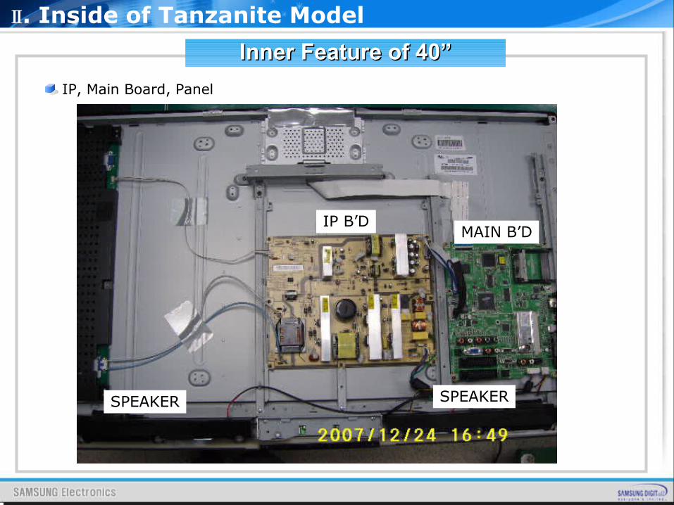
IP, Main Board, Panel
Inner Feature of 40”Inner Feature of 40”
Ⅱ. Inside of Tanzanite Model
SPEAKER
MAIN B’DIP B’D
SPEAKER
My Color Control : Preferred Color Adjustment ( Blue, Green, Pink )
Dynamic Contrast : Enhancing Contrast Ratio (Up to 2000:1)
Brightness Sensor : Sensing the outside brightness and controlling brightness
Some Functions of TanzaniteSome Functions of Tanzanite
Ⅱ. Inside of Tanzanite Model
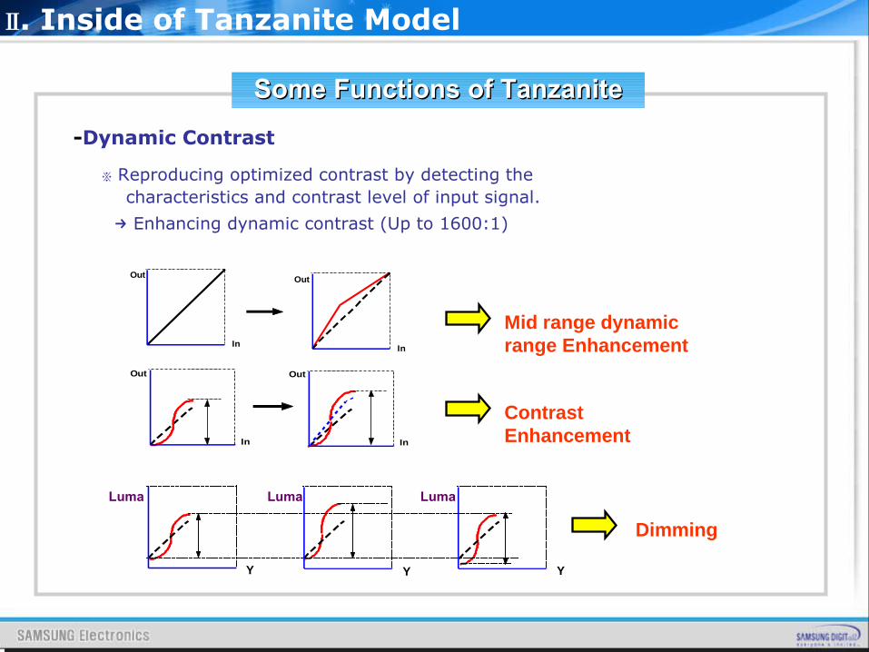
-Dynamic Contrast
※ Reproducing optimized contrast by detecting the characteristics and contrast level of input signal.
→ Enhancing dynamic contrast (Up to 1600:1)
In
Out
In
Out
Out
In
Out
In
Luma
Y Y Y
Mid range dynamic range Enhancement
Contrast Enhancement
Dimming
Luma Luma
Ⅱ. Inside of Tanzanite Model
Some Functions of TanzaniteSome Functions of Tanzanite
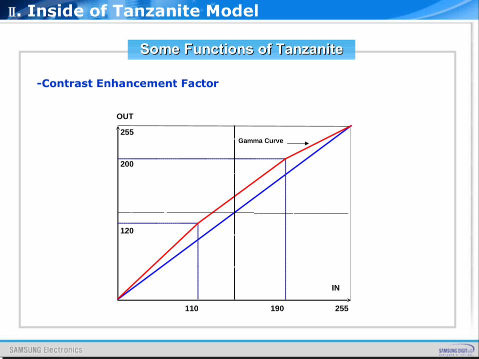
OUT
110 190
120
200
255
255
IN
Gamma Curve
-Contrast Enhancement Factor
Ⅱ. Inside of Tanzanite Model
Some Functions of TanzaniteSome Functions of Tanzanite
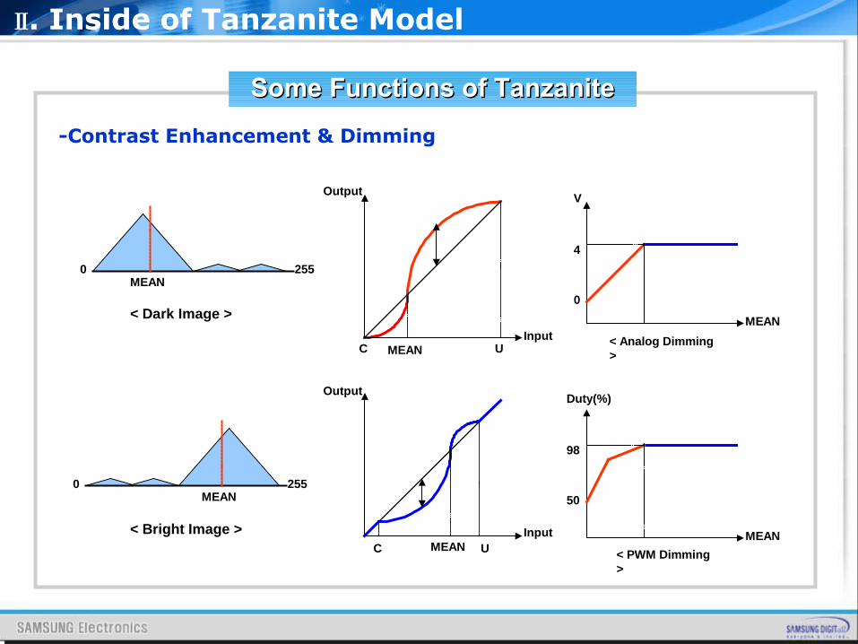
-Contrast Enhancement & Dimming
2550MEAN
2550MEAN
Input
Output
MEAN UC
MEAN
V
4
0
< Analog Dimming >
MEAN
Duty(%)
98
50
< PWM Dimming >
Input
Output
MEAN UC
< Dark Image >
< Bright Image >
Ⅱ. Inside of Tanzanite Model
Some Functions of TanzaniteSome Functions of Tanzanite
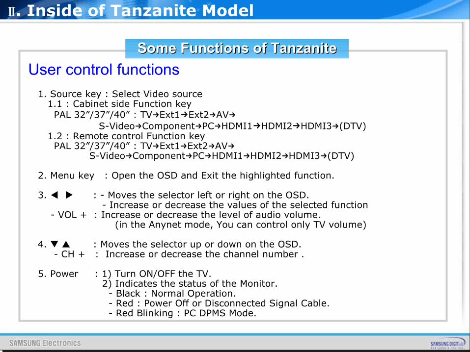
User control functions
1. Source key : Select Video source 1.1 : Cabinet side Function key PAL 32”/37”/40” : TV Ext1→ →Ext2 AV→ → S-Video Component PC HDMI1→ → → →HDMI2→HDMI3 (DTV)→ 1.2 : Remote control Function key PAL 32”/37”/40” : TV Ext1 Ext2 AV→ → → → S-Video Component PC HDMI1 HDMI2 HDMI3 (DTV)→ → → → → →
2. Menu key : Open the OSD and Exit the highlighted function.
3. : - ◀ ▶ Moves the selector left or right on the OSD. - Increase or decrease the values of the selected function - VOL + : Increase or decrease the level of audio volume. (in the Anynet mode, You can control only TV volume)
4. : ▼ ▲ Moves the selector up or down on the OSD. - CH + : Increase or decrease the channel number .
5. Power : 1) Turn ON/OFF the TV. 2) Indicates the status of the Monitor. - Black : Normal Operation. - Red : Power Off or Disconnected Signal Cable. - Red Blinking : PC DPMS Mode.
Ⅱ. Inside of Tanzanite Model
Some Functions of TanzaniteSome Functions of Tanzanite
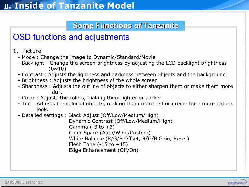
OSD functions and adjustments
1. Picture - Mode : Change the image to Dynamic/Standard/Movie - Backlight : Change the screen brightness by adjusting the LCD backlight brightness (0~10) - Contrast : Adjusts the lightness and darkness between objects and the background. - Brightness : Adjusts the brightness of the whole screen - Sharpness : Adjusts the outline of objects to either sharpen them or make them more dull. - Color : Adjusts the colors, making them lighter or darker - Tint : Adjusts the color of objects, making them more red or greem for a more natural look. - Detailed settings : Black Adjust (Off/Low/Medium/High) Dynamic Contrast (Off/Low/Medium/High) Gamma (-3 to +3) Color Space (Auto/Wide/Custom) White Balance (R/G/B Offset, R/G/B Gain, Reset) Flesh Tone (-15 to +15) Edge Enhancement (Off/On)
Ⅱ. Inside of Tanzanite Model
Some Functions of TanzaniteSome Functions of Tanzanite
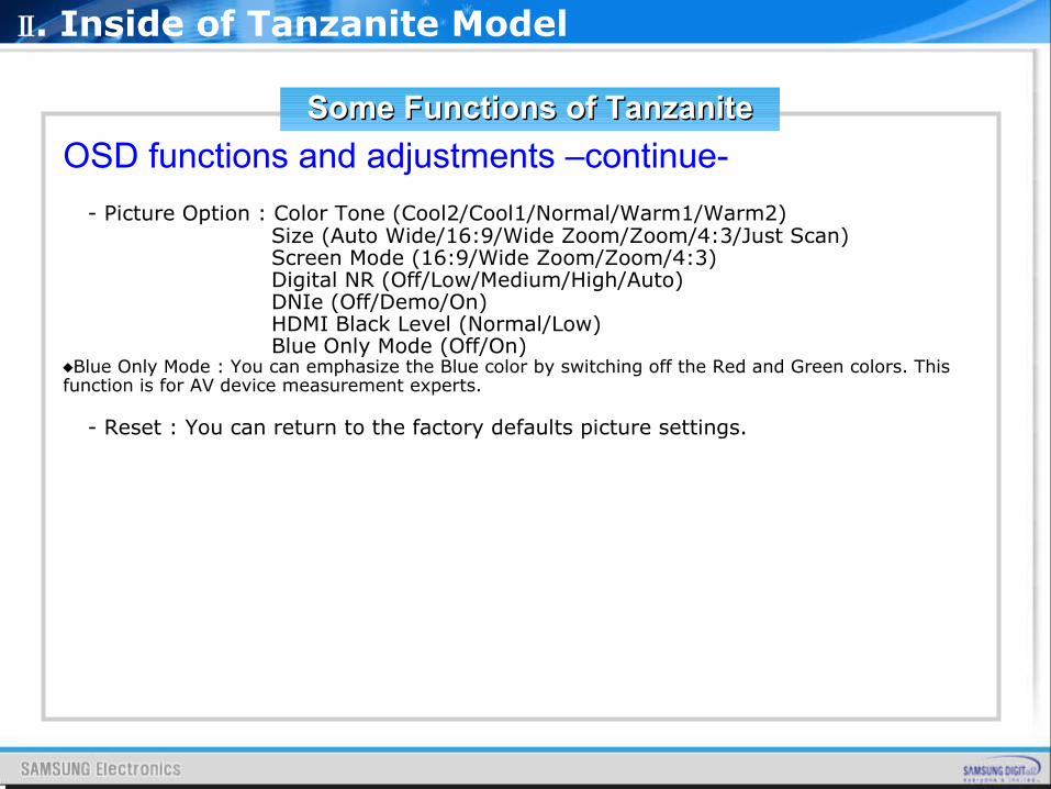
OSD functions and adjustments –continue-
- Picture Option : Color Tone (Cool2/Cool1/Normal/Warm1/Warm2) Size (Auto Wide/16:9/Wide Zoom/Zoom/4:3/Just Scan) Screen Mode (16:9/Wide Zoom/Zoom/4:3) Digital NR (Off/Low/Medium/High/Auto) DNIe (Off/Demo/On) HDMI Black Level (Normal/Low) Blue Only Mode (Off/On)♦Blue Only Mode : You can emphasize the Blue color by switching off the Red and Green colors. This function is for AV device measurement experts.
- Reset : You can return to the factory defaults picture settings.
Ⅱ. Inside of Tanzanite Model
Some Functions of TanzaniteSome Functions of Tanzanite
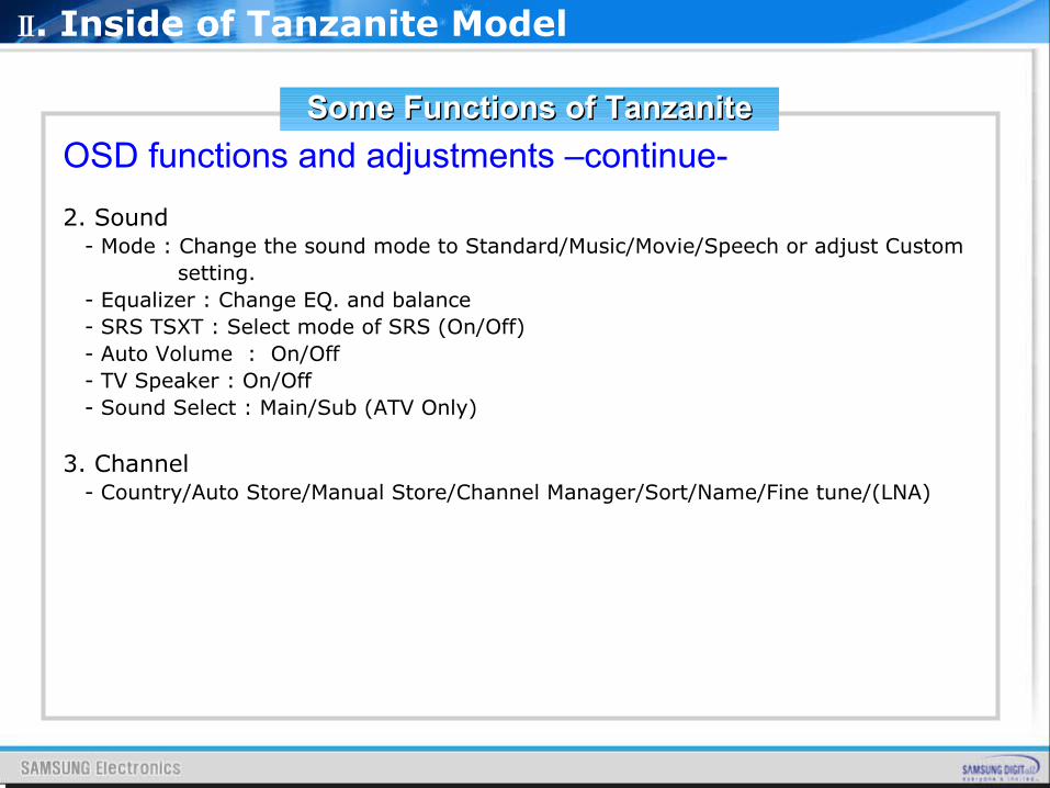
OSD functions and adjustments –continue-
2. Sound - Mode : Change the sound mode to Standard/Music/Movie/Speech or adjust Custom setting. - Equalizer : Change EQ. and balance - SRS TSXT : Select mode of SRS (On/Off) - Auto Volume : On/Off - TV Speaker : On/Off - Sound Select : Main/Sub (ATV Only)
3. Channel - Country/Auto Store/Manual Store/Channel Manager/Sort/Name/Fine tune/(LNA)
Ⅱ. Inside of Tanzanite Model
Some Functions of TanzaniteSome Functions of Tanzanite
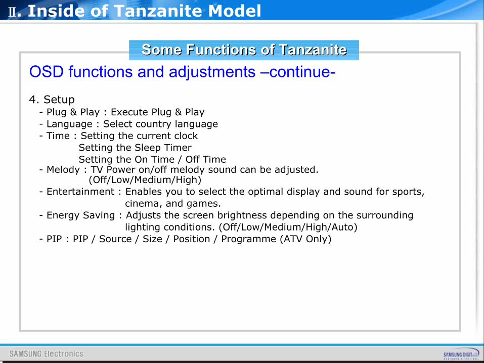
OSD functions and adjustments –continue- 4. Setup - Plug & Play : Execute Plug & Play - Language : Select country language - Time : Setting the current clock Setting the Sleep Timer Setting the On Time / Off Time - Melody : TV Power on/off melody sound can be adjusted. (Off/Low/Medium/High) - Entertainment : Enables you to select the optimal display and sound for sports, cinema, and games. - Energy Saving : Adjusts the screen brightness depending on the surrounding lighting conditions. (Off/Low/Medium/High/Auto) - PIP : PIP / Source / Size / Position / Programme (ATV Only)
Ⅱ. Inside of Tanzanite Model
Some Functions of TanzaniteSome Functions of Tanzanite
OSD functions and adjustments –continue-
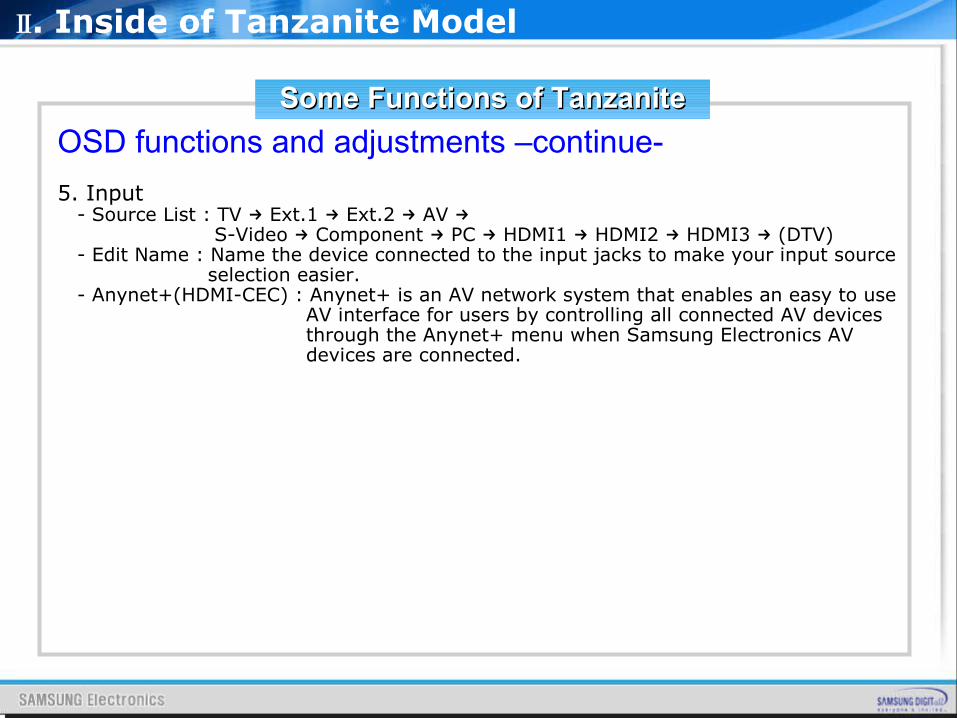
5. Input - Source List : TV → Ext.1 → Ext.2 → AV → S-Video → Component → PC → HDMI1 → HDMI2 → HDMI3 (→ DTV) - Edit Name : Name the device connected to the input jacks to make your input source selection easier. - Anynet+(HDMI-CEC) : Anynet+ is an AV network system that enables an easy to use AV interface for users by controlling all connected AV devices through the Anynet+ menu when Samsung Electronics AV devices are connected.
Ⅱ. Inside of Tanzanite Model
Some Functions of TanzaniteSome Functions of Tanzanite
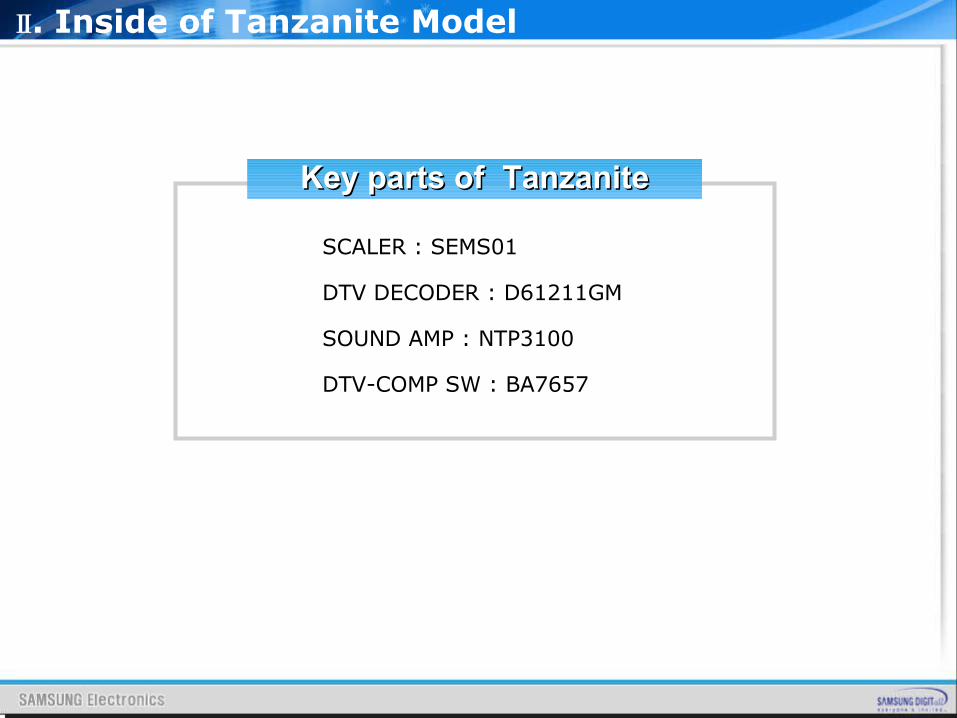
Key parts of Key parts of TanzaniteTanzanite
SCALER : SEMS01
DTV DECODER : D61211GM
SOUND AMP : NTP3100
DTV-COMP SW : BA7657
Ⅱ. Inside of Tanzanite Model
SCALER: SEMS01
Ⅱ. Inside of Tanzanite Model
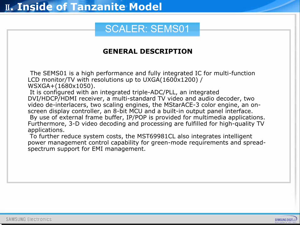
GENERAL DESCRIPTION
The SEMS01 is a high performance and fully integrated IC for multi-function LCD monitor/TV with resolutions up to UXGA(1600x1200) / WSXGA+(1680x1050). It is configured with an integrated triple-ADC/PLL, an integrated DVI/HDCP/HDMI receiver, a multi-standard TV video and audio decoder, two video de-interlacers, two scaling engines, the MStarACE-3 color engine, an on-screen display controller, an 8-bit MCU and a built-in output panel interface. By use of external frame buffer, IP/POP is provided for multimedia applications. Furthermore, 3-D video decoding and processing are fulfilled for high-quality TV applications. To further reduce system costs, the MST69981CL also integrates intelligent power management control capability for green-mode requirements and spread-spectrum support for EMI management.
SCALER: SEMS01
Ⅱ. Inside of Tanzanite Model
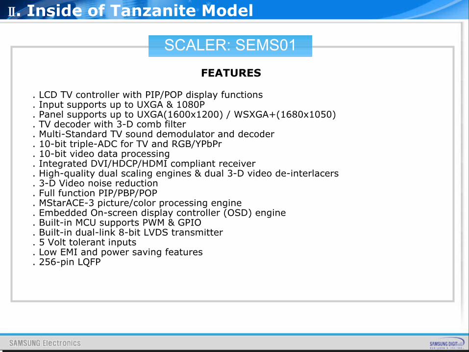
FEATURES
. LCD TV controller with PIP/POP display functions
. Input supports up to UXGA & 1080P
. Panel supports up to UXGA(1600x1200) / WSXGA+(1680x1050)
. TV decoder with 3-D comb filter
. Multi-Standard TV sound demodulator and decoder
. 10-bit triple-ADC for TV and RGB/YPbPr
. 10-bit video data processing
. Integrated DVI/HDCP/HDMI compliant receiver
. High-quality dual scaling engines & dual 3-D video de-interlacers
. 3-D Video noise reduction
. Full function PIP/PBP/POP
. MStarACE-3 picture/color processing engine
. Embedded On-screen display controller (OSD) engine
. Built-in MCU supports PWM & GPIO
. Built-in dual-link 8-bit LVDS transmitter
. 5 Volt tolerant inputs
. Low EMI and power saving features
. 256-pin LQFP
SCALER: SEMS01
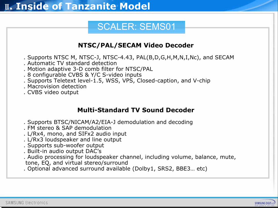
NTSC/PAL/SECAM Video Decoder
. Supports NTSC M, NTSC-J, NTSC-4.43, PAL(B,D,G,H,M,N,I,Nc), and SECAM
. Automatic TV standard detection
. Motion adaptive 3-D comb filter for NTSC/PAL
. 8 configurable CVBS & Y/C S-video inputs
. Supports Teletext level-1.5, WSS, VPS, Closed-caption, and V-chip
. Macrovision detection
. CVBS video output
Multi-Standard TV Sound Decoder
. Supports BTSC/NICAM/A2/EIA-J demodulation and decoding
. FM stereo & SAP demodulation
. L/Rx4, mono, and SIFx2 audio input
. L/Rx3 loudspeaker and line output
. Supports sub-woofer output
. Built-in audio output DAC’s
. Audio processing for loudspeaker channel, including volume, balance, mute, tone, EQ, and virtual stereo/surround. Optional advanced surround available (Dolby1, SRS2, BBE3… etc)
Ⅱ. Inside of Tanzanite Model
SCALER: SEMS01
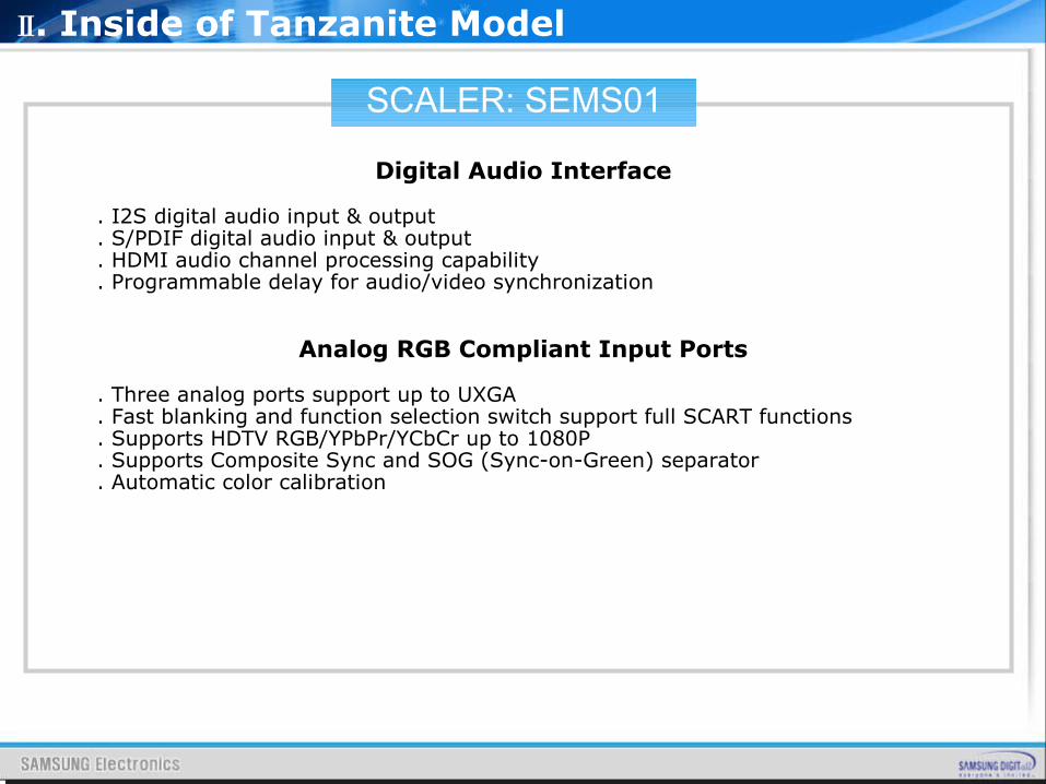
Digital Audio Interface
. I2S digital audio input & output
. S/PDIF digital audio input & output
. HDMI audio channel processing capability
. Programmable delay for audio/video synchronization
Analog RGB Compliant Input Ports
. Three analog ports support up to UXGA
. Fast blanking and function selection switch support full SCART functions
. Supports HDTV RGB/YPbPr/YCbCr up to 1080P
. Supports Composite Sync and SOG (Sync-on-Green) separator
. Automatic color calibration
Ⅱ. Inside of Tanzanite Model
SCALER: SEMS01
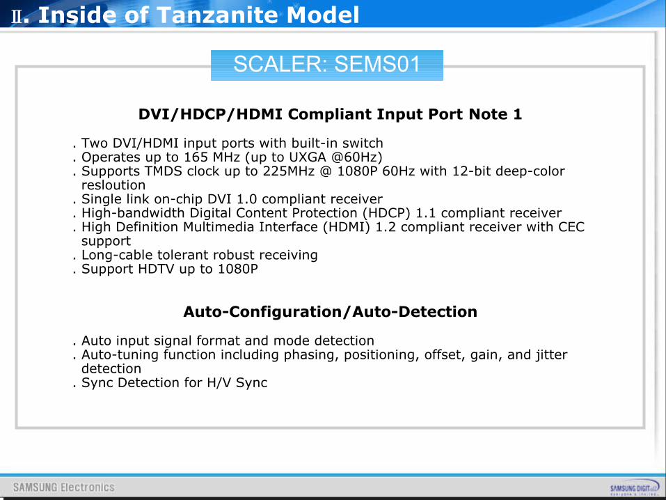
DVI/HDCP/HDMI Compliant Input Port Note 1
. Two DVI/HDMI input ports with built-in switch
. Operates up to 165 MHz (up to UXGA @60Hz)
. Supports TMDS clock up to 225MHz @ 1080P 60Hz with 12-bit deep-color resloution. Single link on-chip DVI 1.0 compliant receiver. High-bandwidth Digital Content Protection (HDCP) 1.1 compliant receiver. High Definition Multimedia Interface (HDMI) 1.2 compliant receiver with CEC support. Long-cable tolerant robust receiving. Support HDTV up to 1080P
Auto-Configuration/Auto-Detection
. Auto input signal format and mode detection
. Auto-tuning function including phasing, positioning, offset, gain, and jitter detection. Sync Detection for H/V Sync
Ⅱ. Inside of Tanzanite Model
SCALER: SEMS01
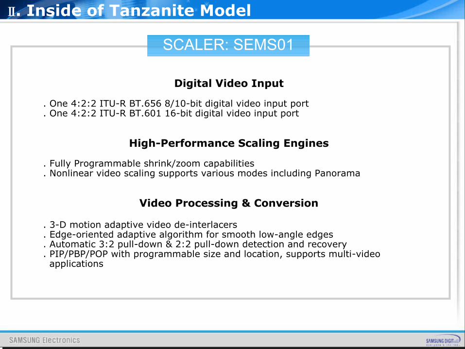
Digital Video Input
. One 4:2:2 ITU-R BT.656 8/10-bit digital video input port
. One 4:2:2 ITU-R BT.601 16-bit digital video input port
High-Performance Scaling Engines
. Fully Programmable shrink/zoom capabilities
. Nonlinear video scaling supports various modes including Panorama
Video Processing & Conversion
. 3-D motion adaptive video de-interlacers
. Edge-oriented adaptive algorithm for smooth low-angle edges
. Automatic 3:2 pull-down & 2:2 pull-down detection and recovery
. PIP/PBP/POP with programmable size and location, supports multi-video applications
Ⅱ. Inside of Tanzanite Model
SCALER: SEMS01
. MStar 3rd Generation Advanced Color Engine (MStarACE-3) automatic picture enhancement gives: - Brilliant and fresh color - Intensified contrast and details - Vivid skin tone - Sharp edge - Enhanced depth of field perception - Accurate and independent color control. sRGB compliance allows end-user to experience the same colors as viewed on CRTs and other displays. Programmable 12-bit RGB gamma CLUT. DLC with 32-segment histogram. 3-D video noise reduction. Frame rate conversion
Ⅱ. Inside of Tanzanite Model
SCALER: SEMS01
On-Screen OSD Controller
. 16/256 color palette
. 256/512 1-bit/pixel font
. 128/256 4-bit/pixel font
. Supports texture function
. Supports 4K attribute/code
. Horizontal and vertical stretch of OSD menus
. Pattern generator for production test
. Supports OSD MUX and alpha blending capability
. Supports blinking and scrolling for closed caption applications
8-bit LVDS/TTL Panel Interface
. Supports dual link LVDS up to UXGA(1600x1200) / WSXGA+(1680x1050)
. Supports 8-bit single TTL panel
. Supports 2 data output formats: Thine & TI data mappings
. Compatible with TIA/EIA
. With 6/8 bits options
. Reduced swing for LVDS for low EMI
. Supports flexible spread spectrum frequency with 360Hz~11.8MHz and up to 25% modulation
Ⅱ. Inside of Tanzanite Model
SCALER: SEMS01
Integrated Micro Controller
. Embedded 8032 micro controller
. Configurable PWM’s and GPIO’s
. Low-speed ADC inputs for system control
. SPI bus for external flash
. Supports external MCU option controlled through 4-wire double-data-rate direct MCU bus or 8-bit direct MCU bus
External Connection/Component
. 16-bit data bus for external frame buffer (SDR or DDR DRAM)
. All system clocks synthesized from a single external clock
Ⅱ. Inside of Tanzanite Model
DECODER:D61211GM
DESCRIPTION
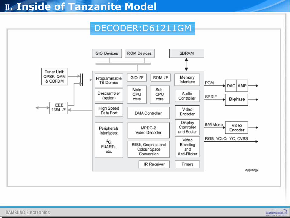
The μPD61211/13 devices, EMMA2SL, are members of the second generation of multimedia processors based on NEC’s Enhanced MultiMedia Architecture (EMMA™). These devices provide nearly all the functionality required to realise a high performance and cost-effective digital set-top box or integrated digital TV.
FEATURES
▪ MPEG1 and MPEG2-TS/PS compliant▪ High performance MIPS32™ 4KEc™ main CPU core▪ High performance MIPS32™ 4KEm™ sub-CPU core▪ Integrated DVB descrambling with family options for Irdeto▪ 36 PID filters, 32 section filters▪ Video Outputs: 4 DACs for RGB, component video, S-video and composite output with support for PAL, NTSC and SECAM▪ 5 graphics planes
Ⅱ. Inside of Tanzanite Model
DECODER:D61211GM
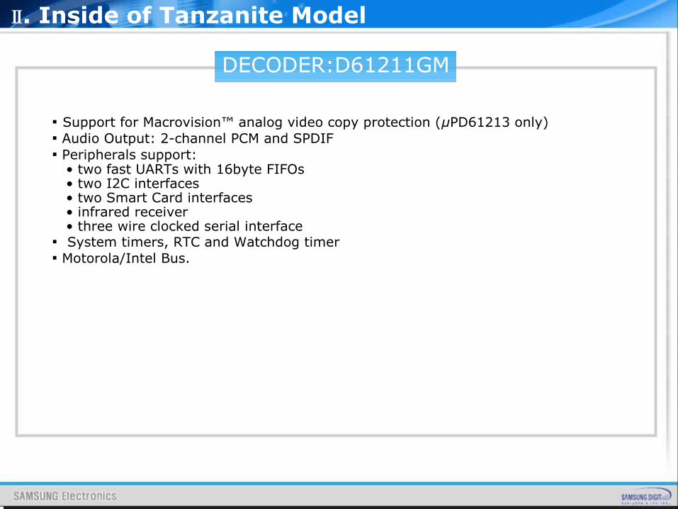
▪ Support for Macrovision™ analog video copy protection (μPD61213 only)▪ Audio Output: 2-channel PCM and SPDIF▪ Peripherals support: • two fast UARTs with 16byte FIFOs • two I2C interfaces • two Smart Card interfaces • infrared receiver • three wire clocked serial interface▪ System timers, RTC and Watchdog timer▪ Motorola/Intel Bus.
Ⅱ. Inside of Tanzanite Model
DECODER:D61211GM
Ⅱ. Inside of Tanzanite Model
DECODER:D61211GM
Main Processor
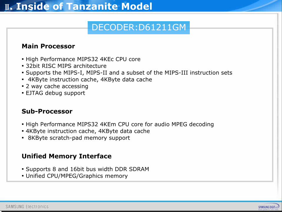
▪ High Performance MIPS32 4KEc CPU core▪ 32bit RISC MIPS architecture▪ Supports the MIPS-I, MIPS-II and a subset of the MIPS-III instruction sets▪ 4KByte instruction cache, 4KByte data cache▪ 2 way cache accessing▪ EJTAG debug support
Sub-Processor
▪ High Performance MIPS32 4KEm CPU core for audio MPEG decoding▪ 4KByte instruction cache, 4KByte data cache▪ 8KByte scratch-pad memory support
Unified Memory Interface
▪ Supports 8 and 16bit bus width DDR SDRAM▪ Unified CPU/MPEG/Graphics memory
Ⅱ. Inside of Tanzanite Model
DECODER:D61211GM
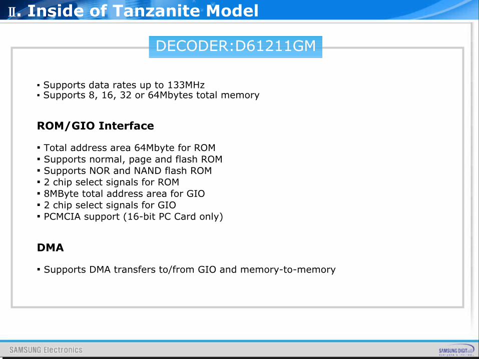
▪ Supports data rates up to 133MHz▪ Supports 8, 16, 32 or 64Mbytes total memory
ROM/GIO Interface
▪ Total address area 64Mbyte for ROM▪ Supports normal, page and flash ROM▪ Supports NOR and NAND flash ROM▪ 2 chip select signals for ROM▪ 8MByte total address area for GIO▪ 2 chip select signals for GIO▪ PCMCIA support (16-bit PC Card only)
DMA
▪ Supports DMA transfers to/from GIO and memory-to-memory
Ⅱ. Inside of Tanzanite Model
DECODER:D61211GM
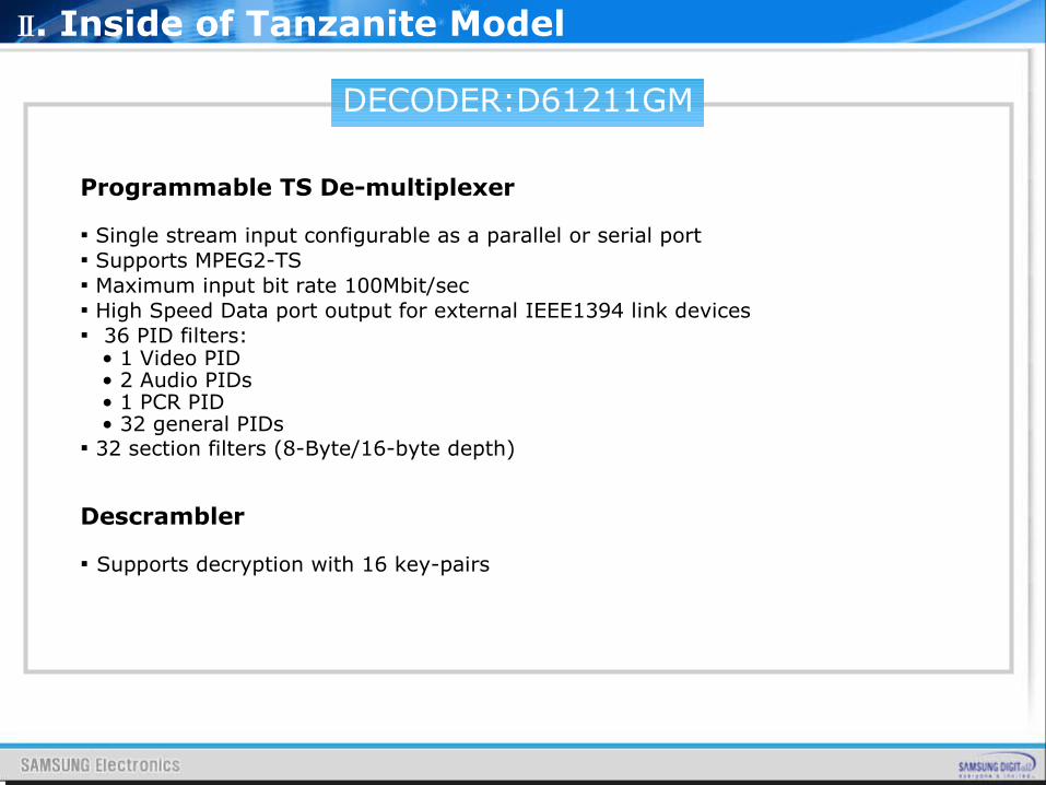
Programmable TS De-multiplexer
▪ Single stream input configurable as a parallel or serial port▪ Supports MPEG2-TS▪ Maximum input bit rate 100Mbit/sec▪ High Speed Data port output for external IEEE1394 link devices▪ 36 PID filters: • 1 Video PID • 2 Audio PIDs • 1 PCR PID • 32 general PIDs▪ 32 section filters (8-Byte/16-byte depth)
Descrambler
▪ Supports decryption with 16 key-pairs
Ⅱ. Inside of Tanzanite Model
DECODER:D61211GM
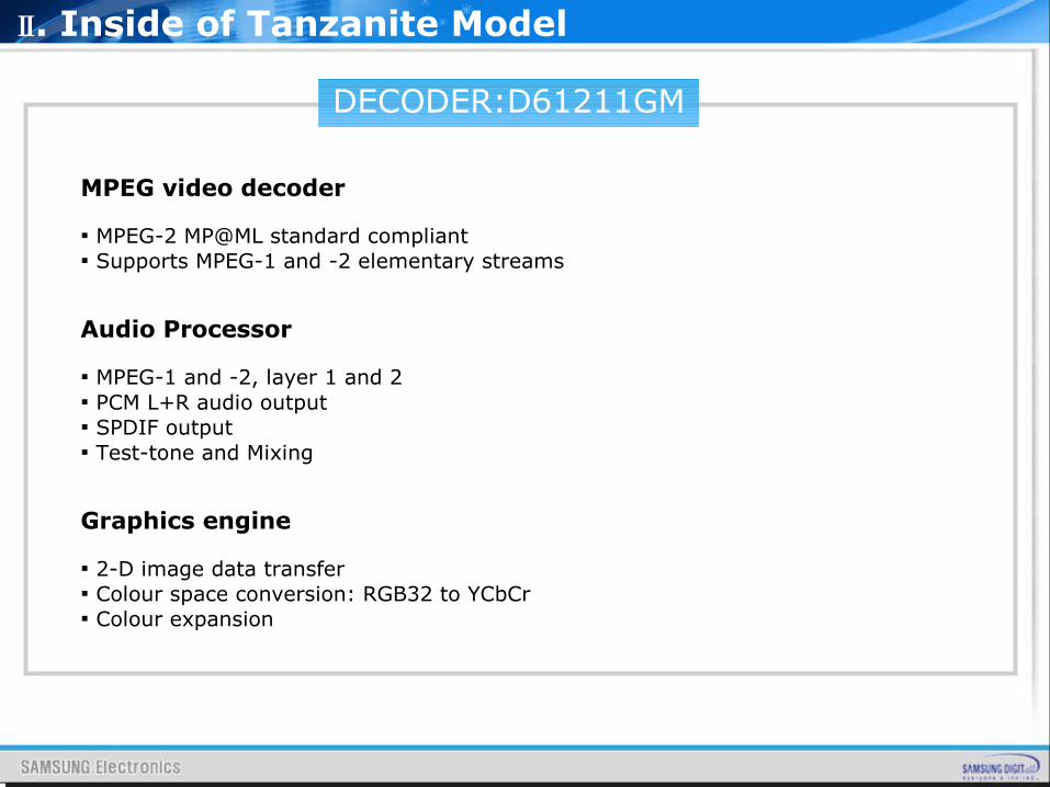
MPEG video decoder
▪ MPEG-2 MP@ML standard compliant▪ Supports MPEG-1 and -2 elementary streams
Audio Processor
▪ MPEG-1 and -2, layer 1 and 2▪ PCM L+R audio output▪ SPDIF output▪ Test-tone and Mixing
Graphics engine
▪ 2-D image data transfer▪ Colour space conversion: RGB32 to YCbCr▪ Colour expansion
Ⅱ. Inside of Tanzanite Model
SOUND AMP:NTP3100
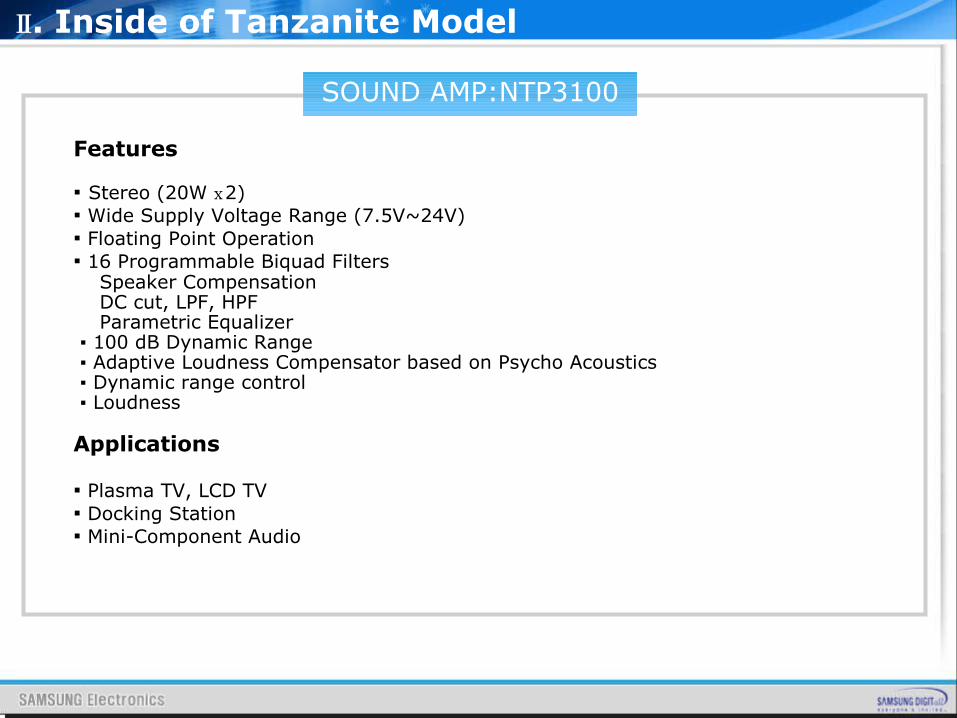
Features ▪ Stereo (20W 2)ⅹ▪ Wide Supply Voltage Range (7.5V~24V)▪ Floating Point Operation▪ 16 Programmable Biquad Filters Speaker Compensation DC cut, LPF, HPF Parametric Equalizer ▪ 100 dB Dynamic Range ▪ Adaptive Loudness Compensator based on Psycho Acoustics ▪ Dynamic range control ▪ Loudness
Applications
▪ Plasma TV, LCD TV▪ Docking Station▪ Mini-Component Audio
Ⅱ. Inside of Tanzanite Model
SOUND AMP:NTP3100
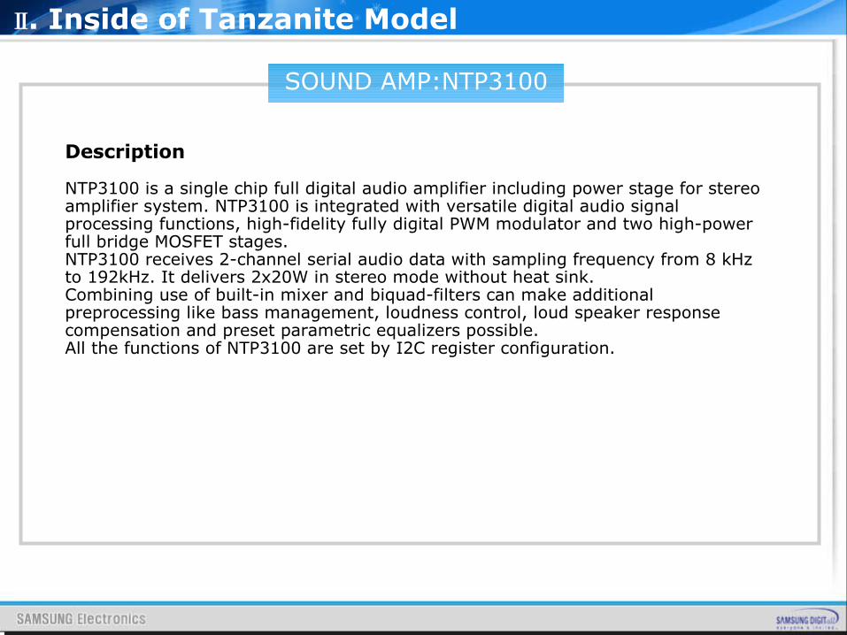
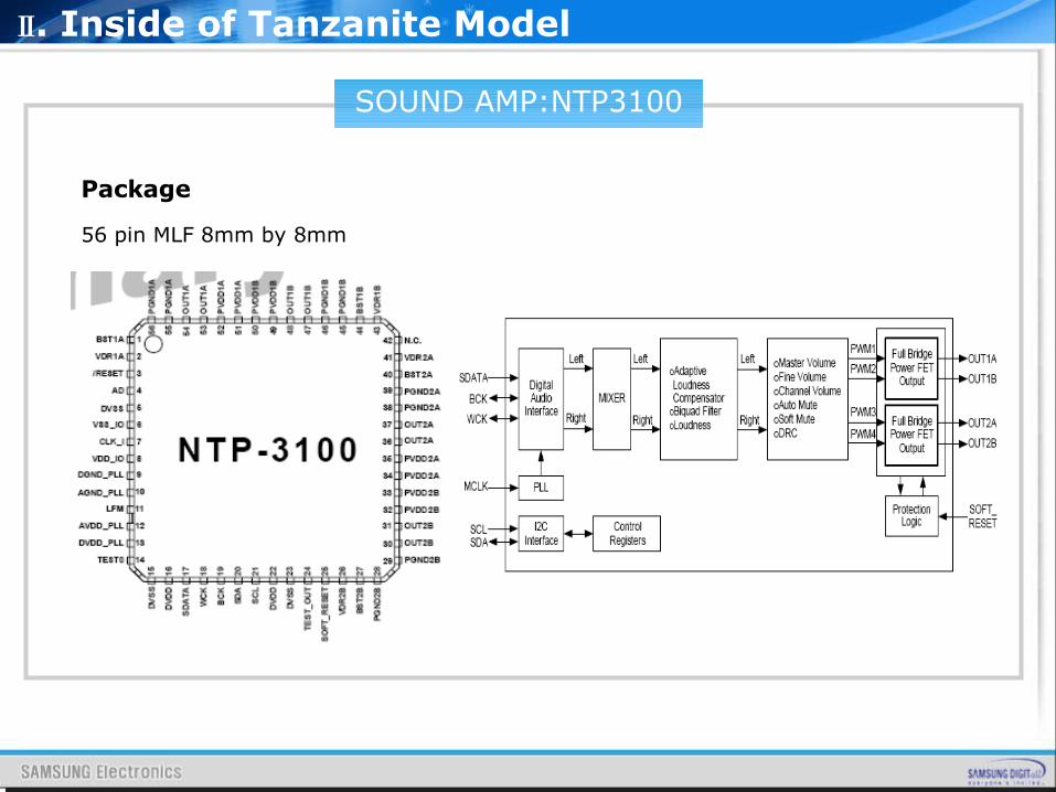
Description
NTP3100 is a single chip full digital audio amplifier including power stage for stereo amplifier system. NTP3100 is integrated with versatile digital audio signal processing functions, high-fidelity fully digital PWM modulator and two high-power full bridge MOSFET stages.NTP3100 receives 2-channel serial audio data with sampling frequency from 8 kHz to 192kHz. It delivers 2x20W in stereo mode without heat sink.Combining use of built-in mixer and biquad-filters can make additional preprocessing like bass management, loudness control, loud speaker response compensation and preset parametric equalizers possible.All the functions of NTP3100 are set by I2C register configuration.
Ⅱ. Inside of Tanzanite Model
SOUND AMP:NTP3100
Package
56 pin MLF 8mm by 8mm
Ⅱ. Inside of Tanzanite Model
SOUND AMP:NTP3100
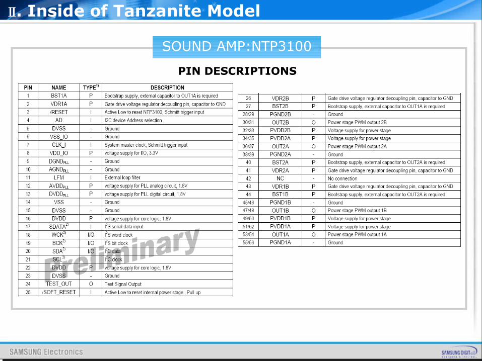
PIN DESCRIPTIONS
Ⅱ. Inside of Tanzanite Model
DTV-COMP SW:BA7657
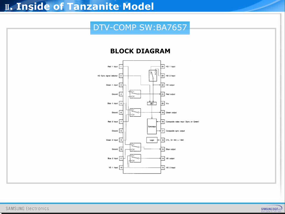
BLOCK DIAGRAM
Ⅱ. Inside of Tanzanite Model
DTV-COMP SW:BA7657
FEATURES
▪ Operates on a single 5V power supply.▪ Internal broadband RGB switch (frequency characteristics : 250MHz, -3dB)▪ Internal HD / VD switch.▪ Internal synchronization separator for synchronizing signals superimposed onto G signals.
Ⅱ. Inside of Tanzanite Model
BOARDDESCRIPTION
Ⅲ. Board description
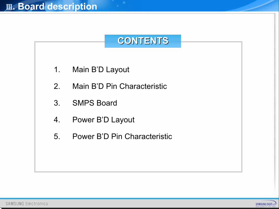
1. Main B’D Layout
2. Main B’D Pin Characteristic
3. SMPS Board
4. Power B’D Layout
5. Power B’D Pin Characteristic
Ⅲ. Board description
CONTENTSCONTENTS
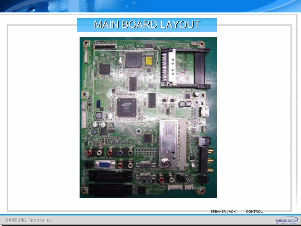
CONTROLSPEAKER JACK
MAIN BOARD LAYOUTMAIN BOARD LAYOUT
Ⅲ. Board description
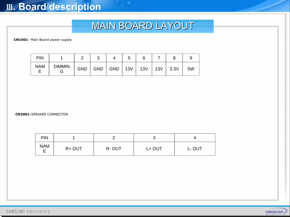
CN1001- Main Board power supply
CN2001-SPEAKER CONNECTOR
MAIN BOARD LAYOUTMAIN BOARD LAYOUT
PIN 1 2 3 4 5 6 7 8 9
NAME
DIMMING GND GND GND 13V 13V 13V 3.3V SW
PIN 1 2 3 4
NAME R+ OUT R- OUT L+ OUT L- OUT
Ⅲ. Board description
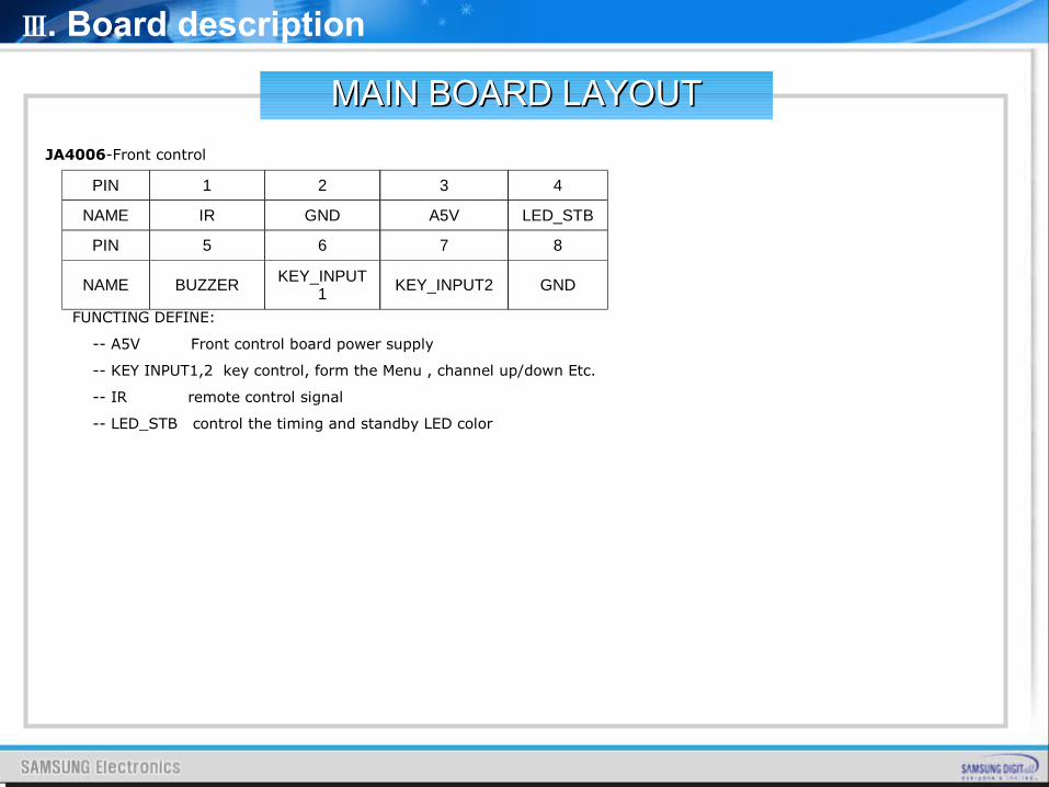
JA4006-Front control
FUNCTING DEFINE:
-- A5V Front control board power supply
-- KEY INPUT1,2 key control, form the Menu , channel up/down Etc.
-- IR remote control signal
-- LED_STB control the timing and standby LED color
PIN 1 2 3 4
NAME IR GND A5V LED_STB
PIN 5 6 7 8
NAME BUZZER KEY_INPUT1
KEY_INPUT2 GND
MAIN BOARD LAYOUTMAIN BOARD LAYOUT
Ⅲ. Board description
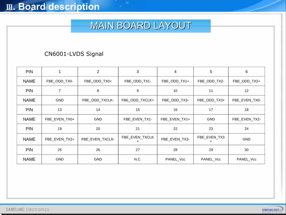
CN6001-LVDS Signal
PIN 1 2 3 4 5 6
NAME FBE_ODD_TX0- FBE_ODD_TX0+ FBE_ODD_TX1- FBE_ODD_TX1+ FBE_ODD_TX2- FBE_ODD_TX2+
PIN 7 8 9 10 11 12
NAME GND FBE_ODD_TXCLK- FBE_ODD_TXCLK+ FBE_ODD_TX3- FBE_ODD_TX3+ FBE_EVEN_TX0-
PIN 13 14 15 16 17 18
NAME FBE_EVEN_TX0+ GND FBE_EVEN_TX1- FBE_EVEN_TX1+ GND FBE_EVEN_TX2-
PIN 19 20 21 22 23 24
NAME FBE_EVEN_TX2+ FBE_EVEN_TXCLK- FBE_EVEN_TXCLK+ FBE_EVEN_TX3- FBE_EVEN_TX3
+ GND
PIN 25 26 27 28 29 30
NAME GND GND N.C. PANEL_Vcc PANEL_Vcc PANEL_Vcc
MAIN BOARD LAYOUTMAIN BOARD LAYOUT
Ⅲ. Board description
IP SPECIP SPEC
MAIN BOARD LAYOUTMAIN BOARD LAYOUT
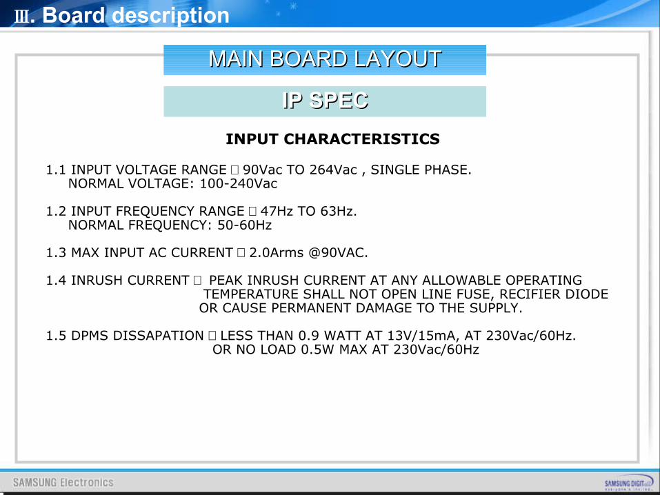
INPUT CHARACTERISTICS
1.1 INPUT VOLTAGE RANGE : 90Vac TO 264Vac , SINGLE PHASE. NORMAL VOLTAGE: 100-240Vac
1.2 INPUT FREQUENCY RANGE : 47Hz TO 63Hz. NORMAL FREQUENCY: 50-60Hz
1.3 MAX INPUT AC CURRENT : 2.0Arms @90VAC.
1.4 INRUSH CURRENT : PEAK INRUSH CURRENT AT ANY ALLOWABLE OPERATING TEMPERATURE SHALL NOT OPEN LINE FUSE, RECIFIER DIODE OR CAUSE PERMANENT DAMAGE TO THE SUPPLY.
1.5 DPMS DISSAPATION : LESS THAN 0.9 WATT AT 13V/15mA, AT 230Vac/60Hz. OR NO LOAD 0.5W MAX AT 230Vac/60Hz
Ⅲ. Board description
IP SPECIP SPEC
MAIN BOARD LAYOUTMAIN BOARD LAYOUT
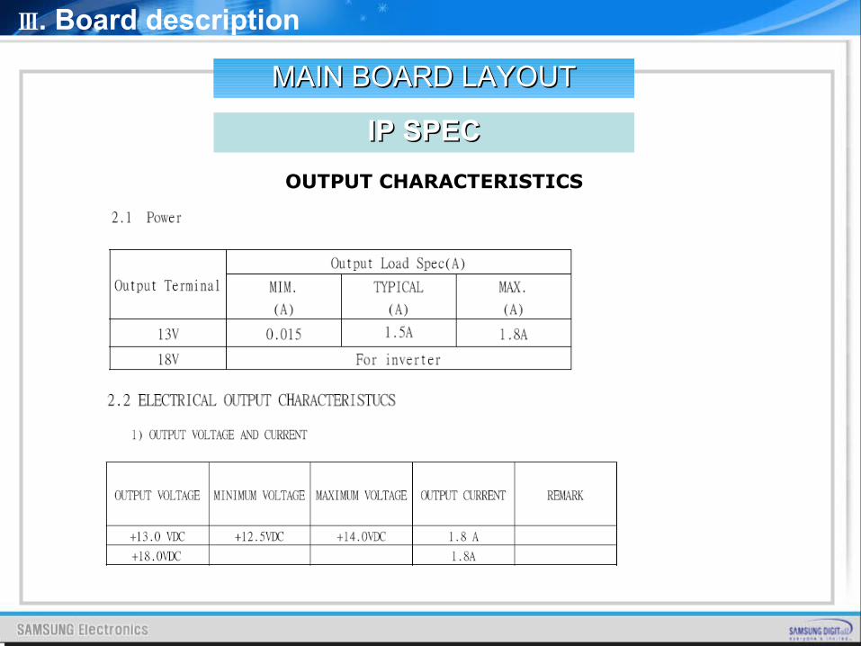
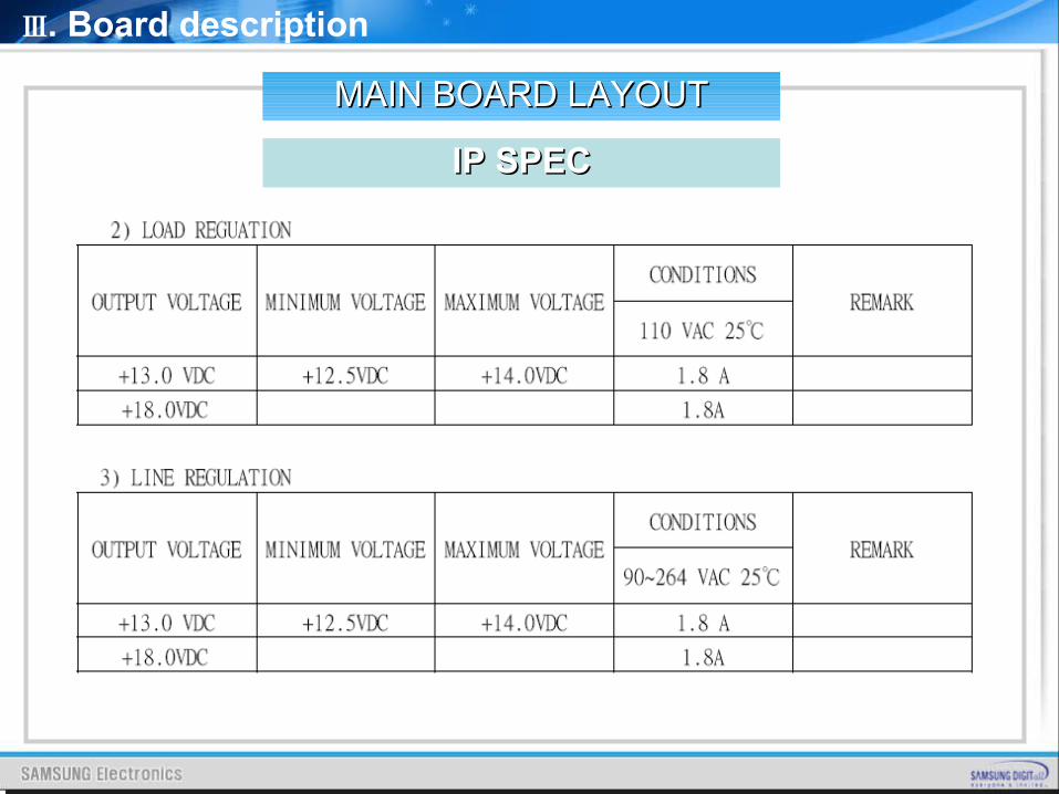
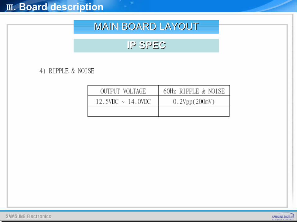
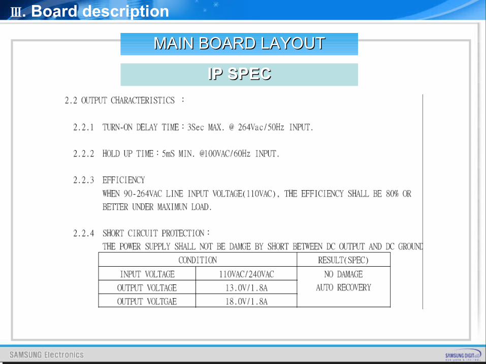
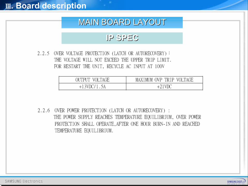
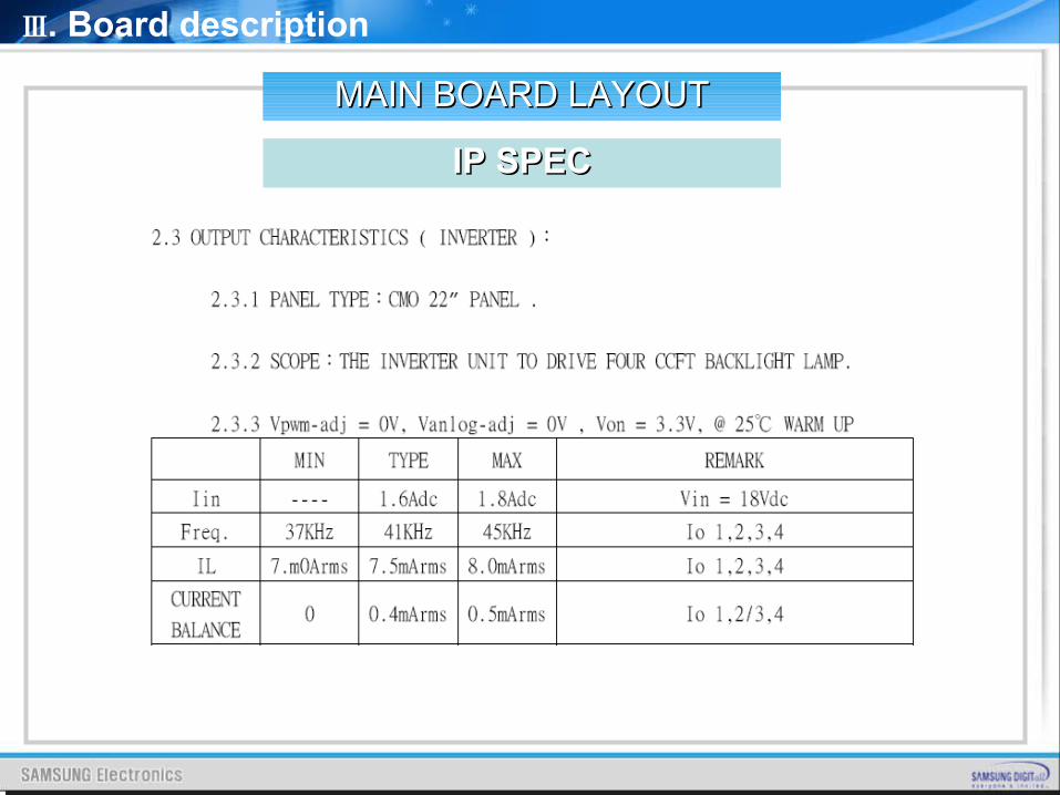
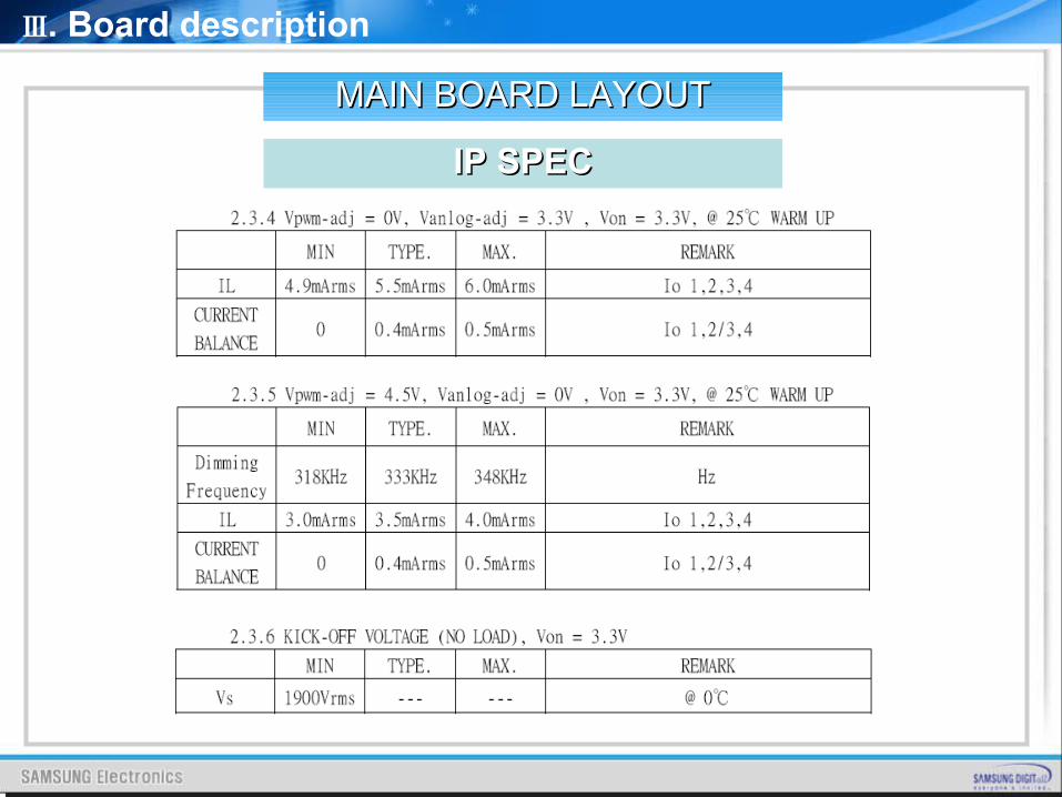
OUTPUT CHARACTERISTICS
Ⅲ. Board description
IP SPECIP SPEC
MAIN BOARD LAYOUTMAIN BOARD LAYOUT
Ⅲ. Board description
IP SPECIP SPEC
MAIN BOARD LAYOUTMAIN BOARD LAYOUT
Ⅲ. Board description
IP SPECIP SPEC
MAIN BOARD LAYOUTMAIN BOARD LAYOUT
Ⅲ. Board description
IP SPECIP SPEC
MAIN BOARD LAYOUTMAIN BOARD LAYOUT
Ⅲ. Board description
IP SPECIP SPEC
MAIN BOARD LAYOUTMAIN BOARD LAYOUT
Ⅲ. Board description
IP SPECIP SPEC
MAIN BOARD LAYOUTMAIN BOARD LAYOUT
Ⅲ. Board description
IP SPECIP SPEC
MAIN BOARD LAYOUTMAIN BOARD LAYOUT
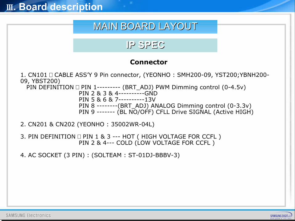
Connector
1. CN101 : CABLE ASS’Y 9 Pin connector, (YEONHO : SMH200-09, YST200;YBNH200-09, YBST200) PIN DEFINITION : PIN 1--------- (BRT_ADJ) PWM Dimming control (0-4.5v) PIN 2 & 3 & 4----------GND PIN 5 & 6 & 7----------13V PIN 8 --------(BRT_ADJ) ANALOG Dimming control (0-3.3v) PIN 9 ------- (BL NO/OFF) CFLL Drive SIGNAL (Active HIGH)
2. CN201 & CN202 (YEONHO : 35002WR-04L)
3. PIN DEFINITION : PIN 1 & 3 --- HOT ( HIGH VOLTAGE FOR CCFL ) PIN 2 & 4--- COLD (LOW VOLTAGE FOR CCFL )
4. AC SOCKET (3 PIN) : (SOLTEAM : ST-01DJ-BBBV-3)
Ⅲ. Board description
IP SPECIP SPEC
MAIN BOARD LAYOUTMAIN BOARD LAYOUT
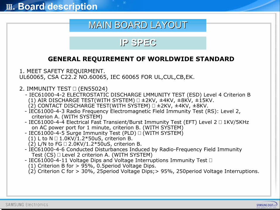
GENERAL REQUIREMENT OF WORLDWIDE STANDARD
1. MEET SAFETY REQUIRMENT.UL60065, CSA C22.2 NO.60065, IEC 60065 FOR UL,CUL,CB,EK.
2. IMMUNITY TEST : (EN55024) - IEC61000-4-2 ELECTROSTATIC DISCHARGE LMMUNITY TEST (ESD) Level 4 Criterion B (1) AIR DISCHARGE TEST(WITH SYSTEM) : ±2KV, ±4KV, ±8KV, ±15KV. (2) CONTACT DISCHARGE TEST(WITH SYSTEM) : ±2KV, ±4KV, ±8KV. - IEC61000-4-3 Radio Frequency Electromagnetic Field Immunity Test (RS): Level 2, criterion A. (WITH SYSTEM) - IEC61000-4-4 Electrical Fast Transient/Burst Immunity Test (EFT) Level 2 : 1KV/5KHz on AC power port for 1 minute, criterion B. (WITH SYSTEM) - IEC61000-4-5 Surge Immunity Test (PLD) : (WITH SYSTEM) (1) L to N : 1.0KV/1.2*50uS, criterion B. (2) L/N to FG : 2.0KV/1.2*50uS, criterion B. - IEC61000-4-6 Conducted Disturbances Induced by Radio-Frequency Field Immunity Test (CS) : Level 2 criterion A. (WITH SYSTEM) - IEC61000-4-11 Voltage Dips and Voltage Interruptions Immunity Test : (1) Criterion B for > 95%, 0.5period Voltage Dips. (2) Criterion C for > 30%, 25period Voltage Dips;> 95%, 250period Voltage Interruptions.

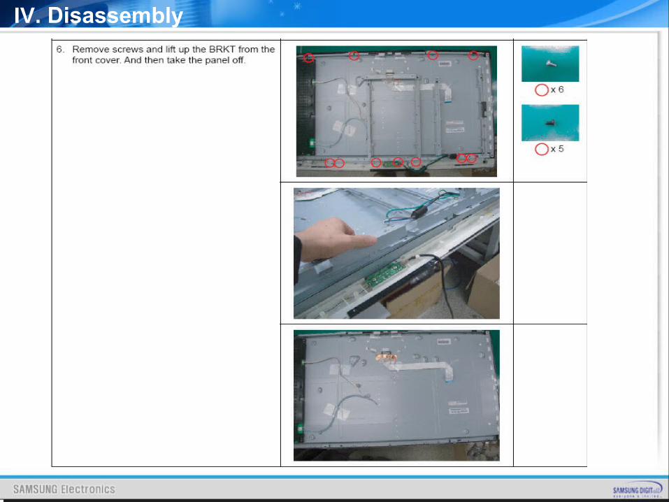
IV. Disassembly
DISASSEMBLY
IV. Disassembly
Disassembly Tanzanite
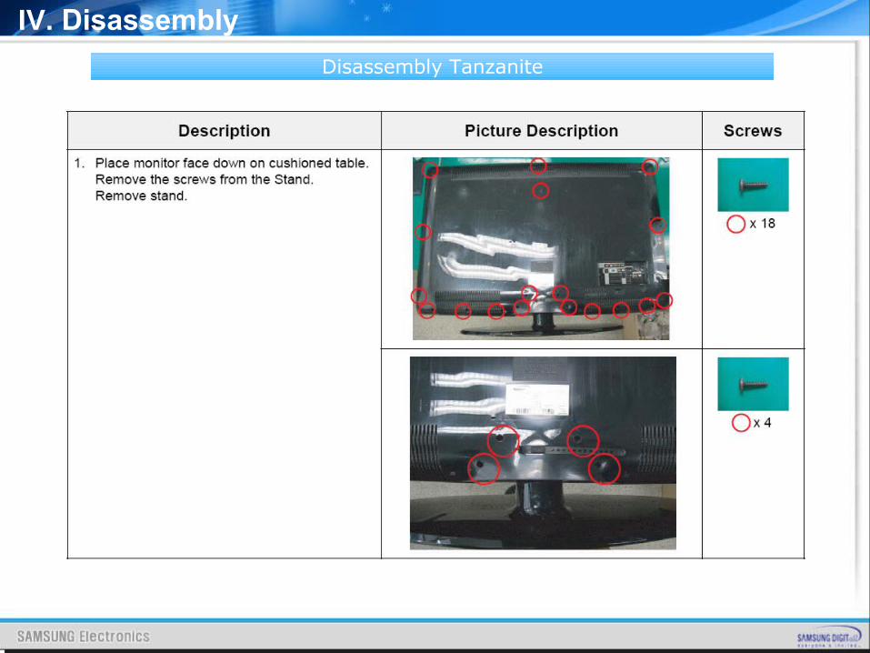
IV. Disassembly
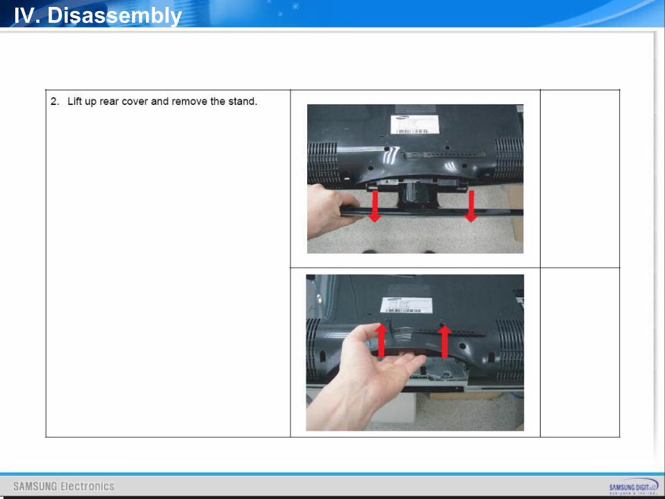
IV. Disassembly
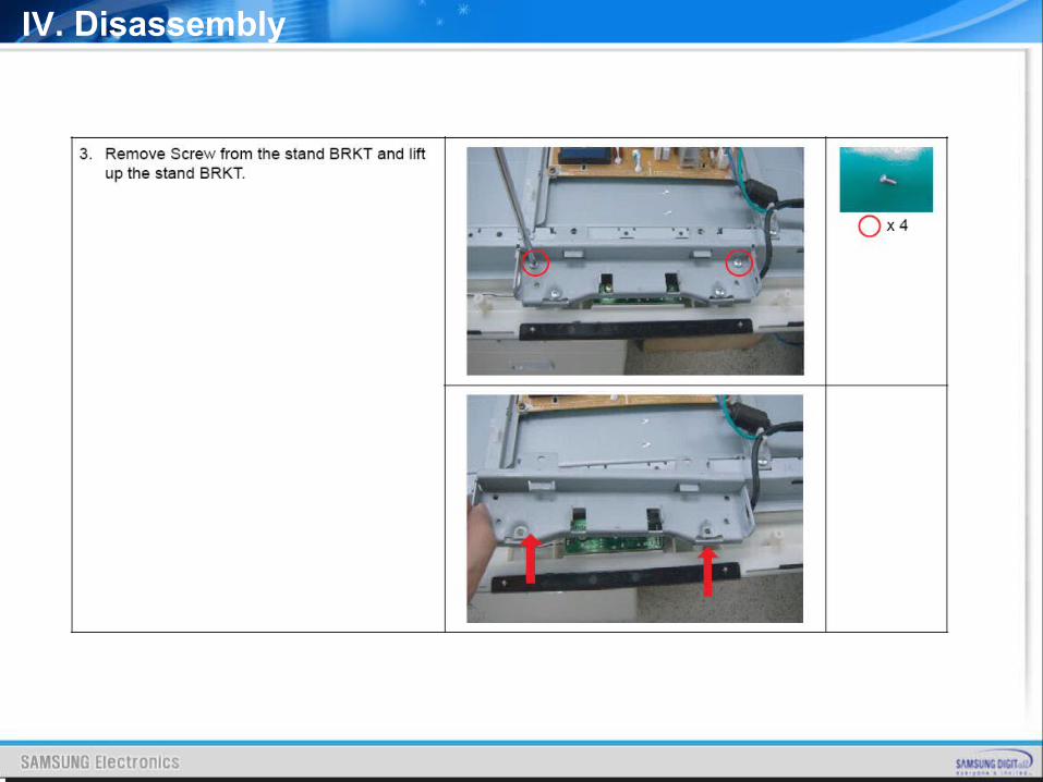
IV. Disassembly
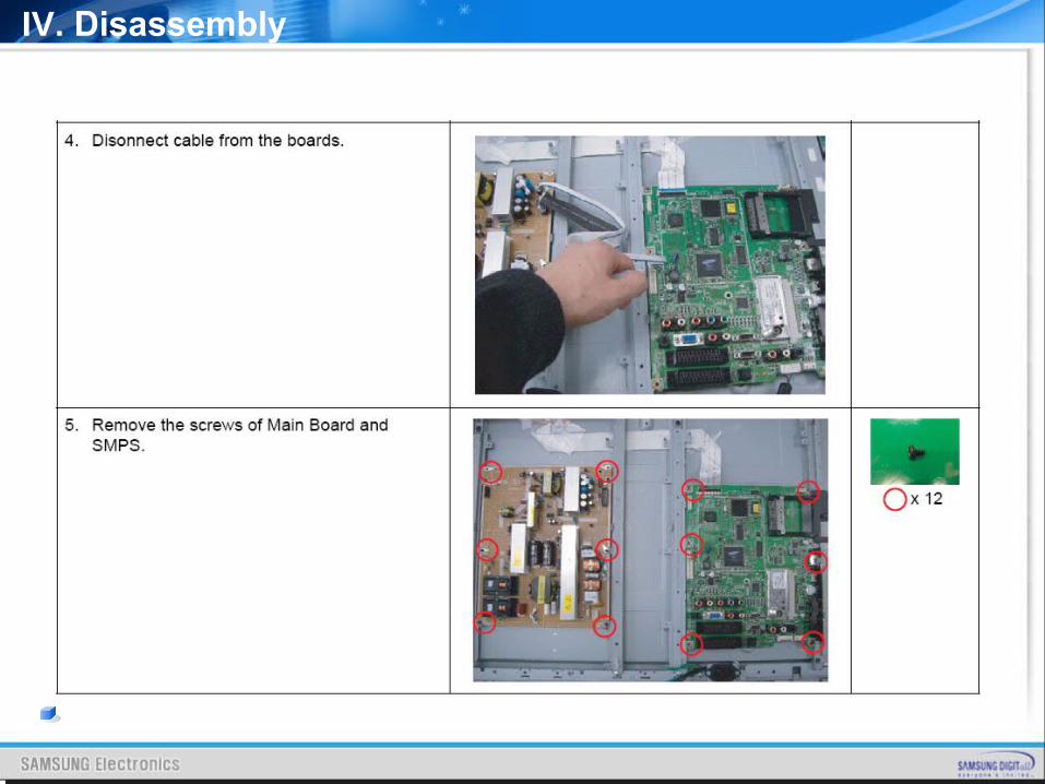
IV. Disassembly
V. Trouble Shooting
TROUBLESHOOTING
CONTENTSCONTENTS
V. Trouble Shooting
I. Power Trouble Shooting
II. Analog Part
III. Digital Part
IV. Sound Part
V. Flow Chart & Waveforms
VI. White Balance
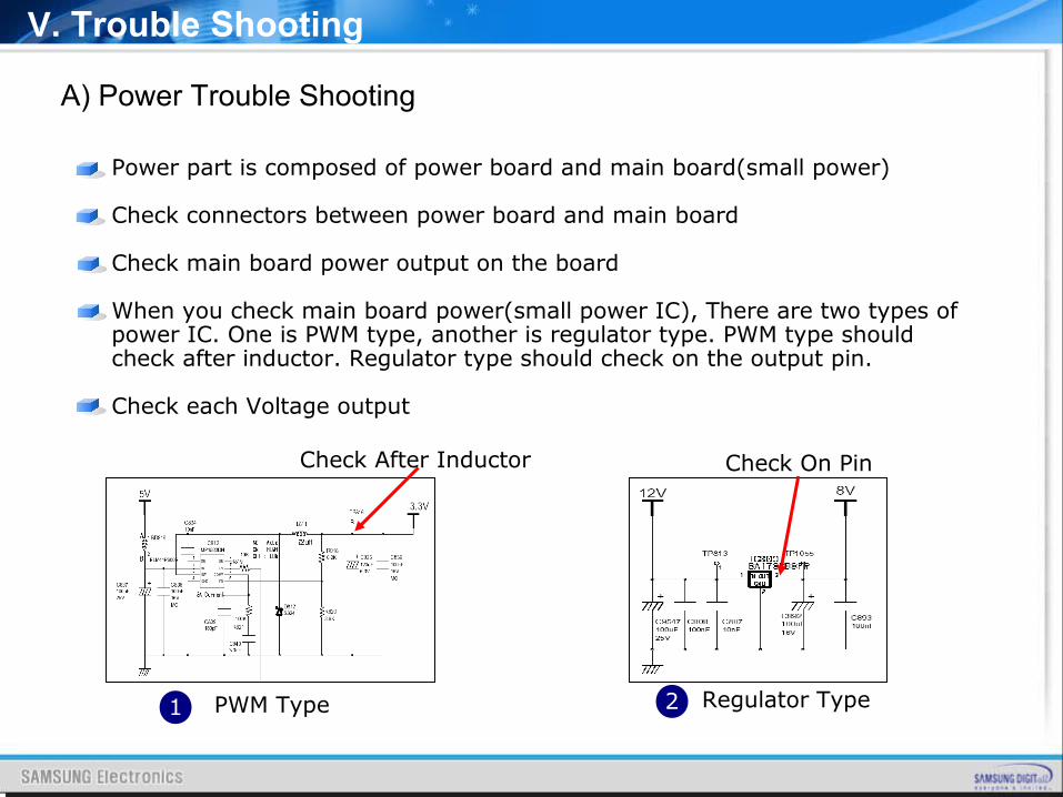
A) Power Trouble Shooting
Power part is composed of power board and main board(small power)
Check connectors between power board and main board
Check main board power output on the board
When you check main board power(small power IC), There are two types of power IC. One is PWM type, another is regulator type. PWM type should check after inductor. Regulator type should check on the output pin.
Check each Voltage output
1 PWM Type 2 Regulator Type
Check After Inductor Check On Pin
V. Trouble Shooting
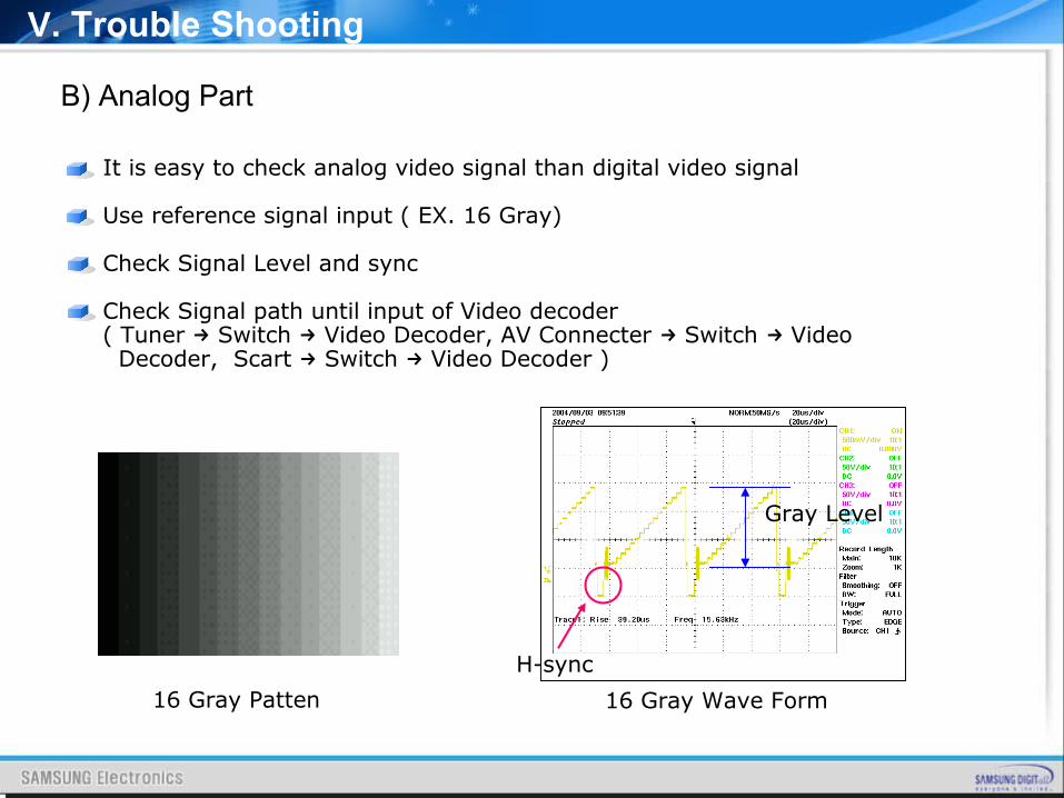
B) Analog Part
It is easy to check analog video signal than digital video signal
Use reference signal input ( EX. 16 Gray)
Check Signal Level and sync
Check Signal path until input of Video decoder ( Tuner Switch Video Decoder, AV Connecter Switch Video→ → → → Decoder, Scart Switch Video Decoder )→ →
16 Gray Patten 16 Gray Wave Form
H-sync
Gray Level
V. Trouble Shooting
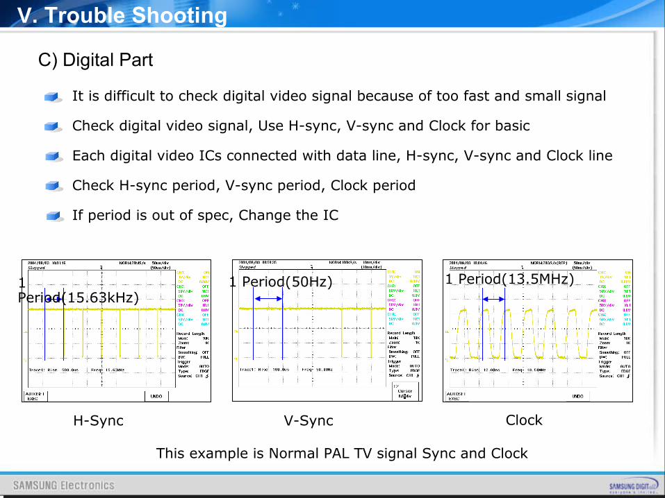
C) Digital Part
It is difficult to check digital video signal because of too fast and small signal
Check digital video signal, Use H-sync, V-sync and Clock for basic
Each digital video ICs connected with data line, H-sync, V-sync and Clock line
Check H-sync period, V-sync period, Clock period If period is out of spec, Change the IC
H-Sync
1 Period(15.63kHz)
V-Sync
1 Period(50Hz)
Clock
1 Period(13.5MHz)
V. Trouble Shooting
This example is Normal PAL TV signal Sync and Clock
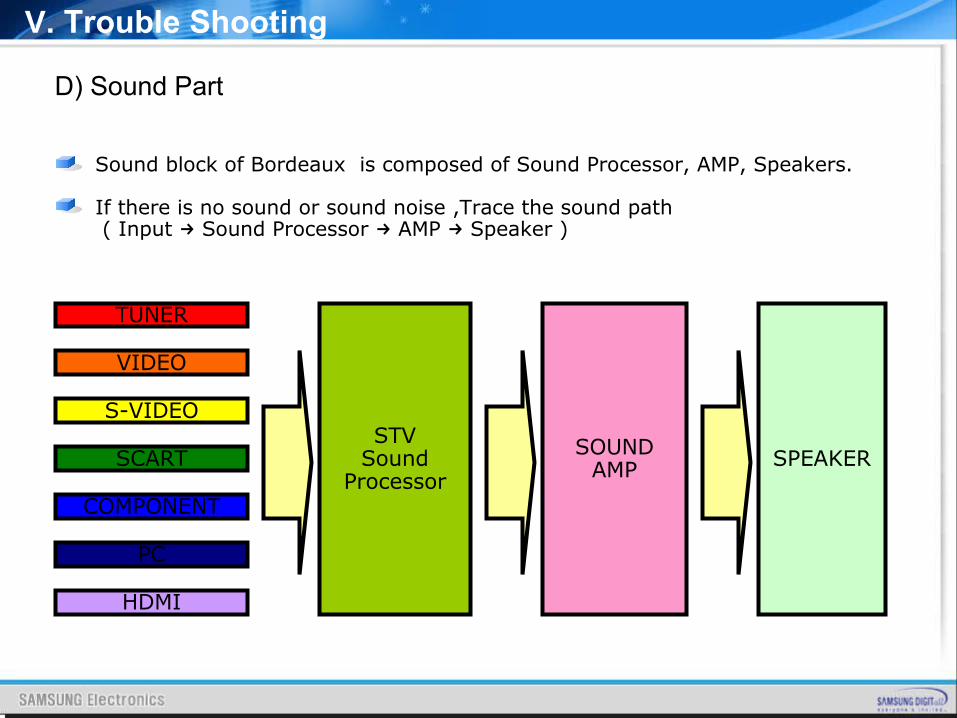
D) Sound Part
Sound block of Bordeaux is composed of Sound Processor, AMP, Speakers.
If there is no sound or sound noise ,Trace the sound path ( Input Sound Processor AMP Speaker )→ → →
V. Trouble Shooting
TUNER
VIDEO
S-VIDEO
SCART
COMPONENT
PC
HDMI
SOUNDAMP
STVSound
ProcessorSPEAKER
V. Trouble Shooting
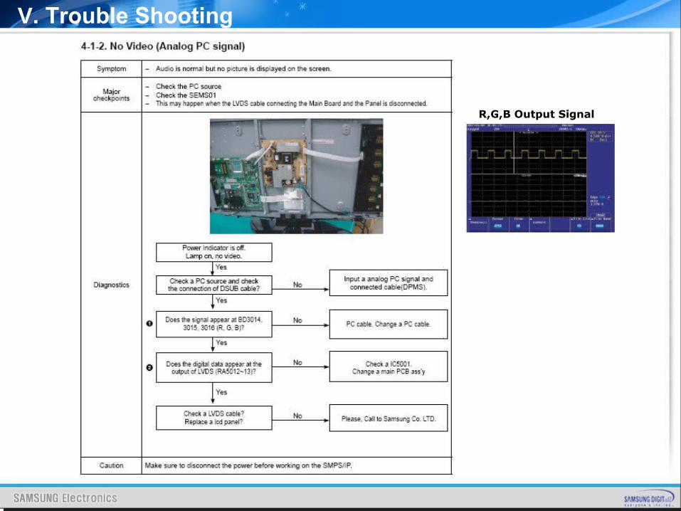
V. Trouble Shooting
R,G,B Output Signal
V. Trouble Shooting
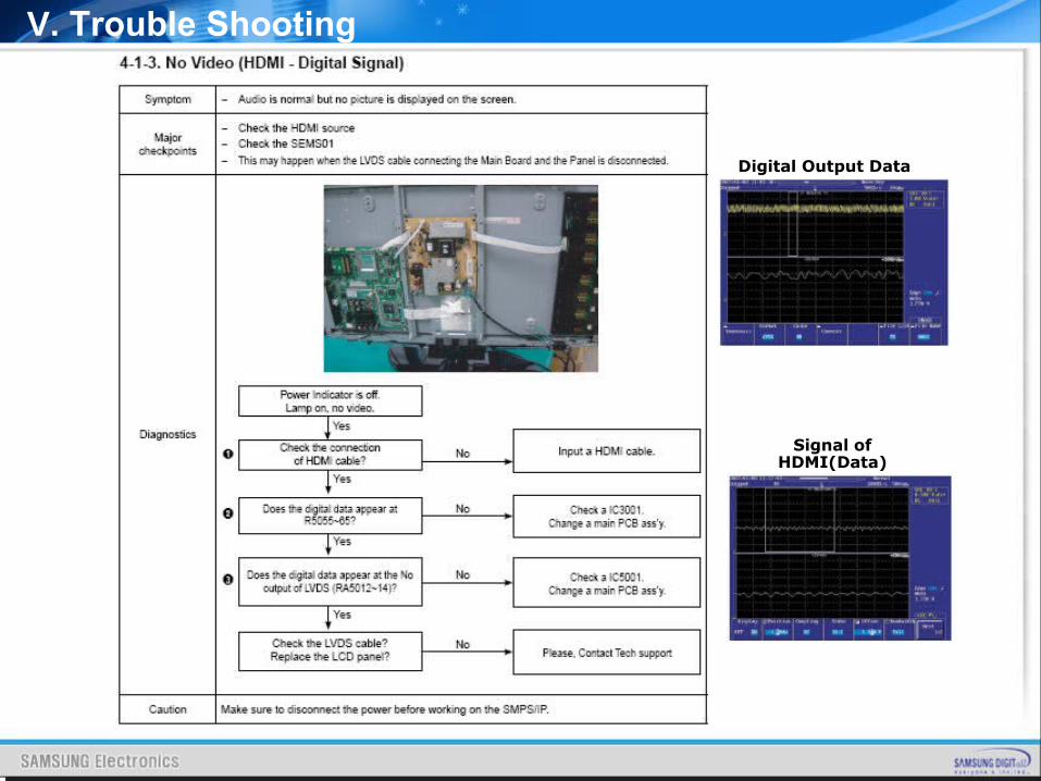
Digital Output Data
Signal of HDMI(Data)
V. Trouble Shooting
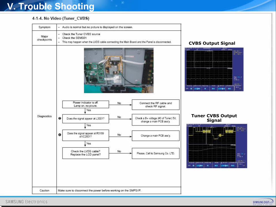
CVBS Output Signal
Tuner CVBS Output Signal
V. Trouble Shooting
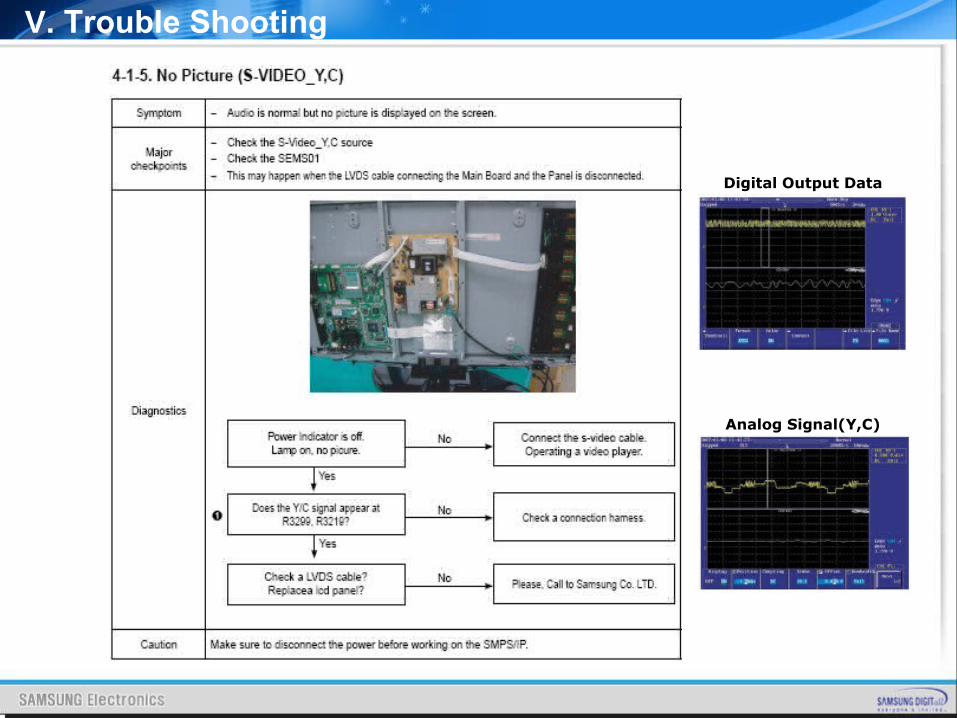
Digital Output Data
Analog Signal(Y,C)
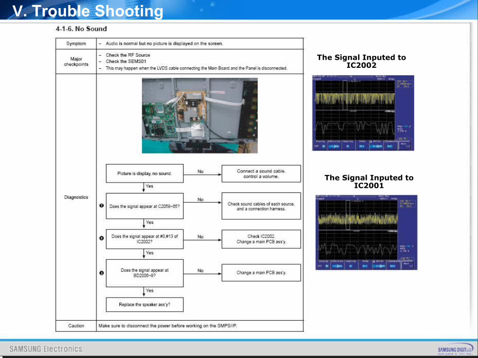
V. Trouble Shooting
The Signal Inputed to IC2002
The Signal Inputed to IC2001
V. Trouble Shooting
HOW TO UPGRADE
HOW TO UPGRADEHOW TO UPGRADE
VI. How to Upgrade
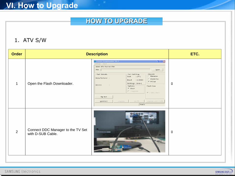
1. ATV S/W
Order Description ETC.
1 Open the Flash Downloader.
2 Connect DDC Manager to the TV Set with D-SUB Cable.
HOW TO UPGRADEHOW TO UPGRADE
VI. How to Upgrade
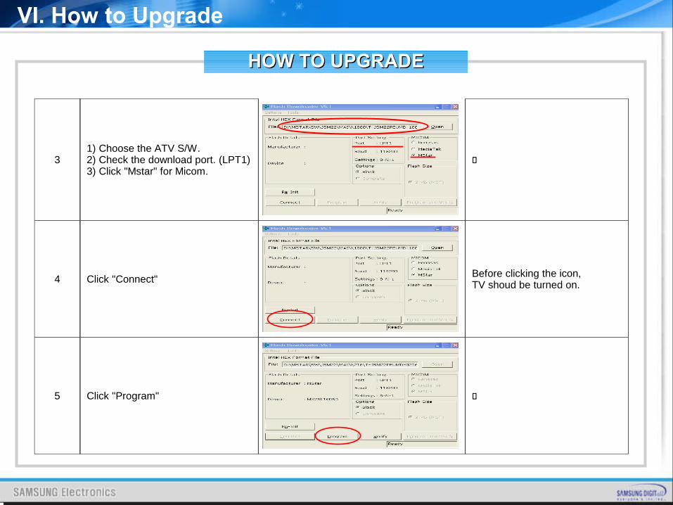
31) Choose the ATV S/W.2) Check the download port. (LPT1)3) Click "Mstar" for Micom.
4 Click "Connect" Before clicking the icon, TV shoud be turned on.
5 Click "Program"
HOW TO UPGRADEHOW TO UPGRADE
VI. How to Upgrade
2. DTV S/W
Order Description ETC.
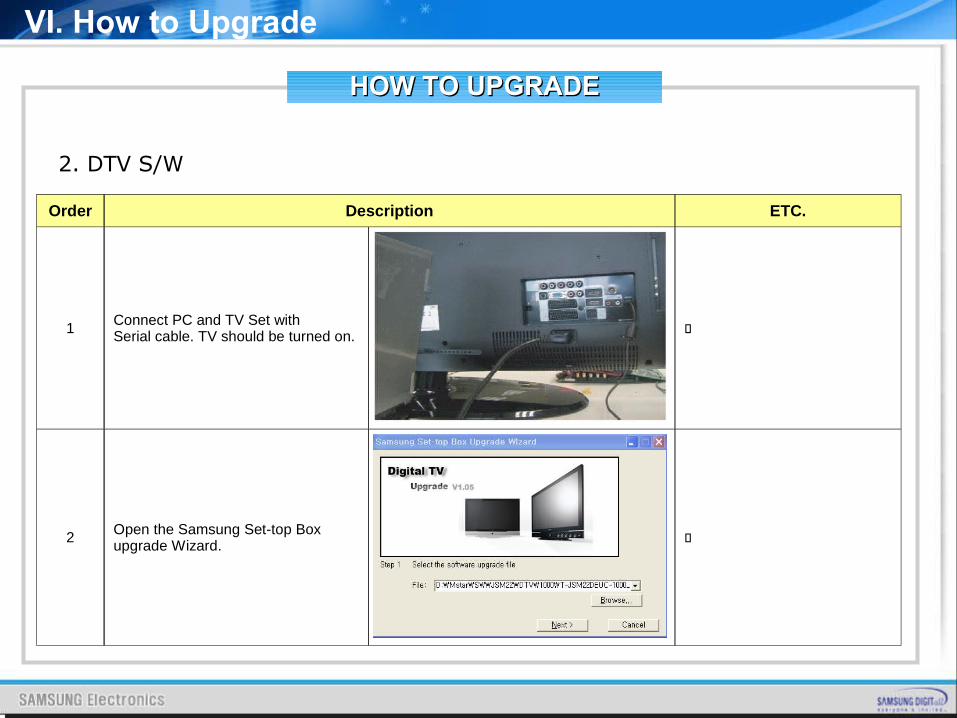
1Connect PC and TV Set with Serial cable. TV should be turned on.
2 Open the Samsung Set-top Box upgrade Wizard.
HOW TO UPGRADEHOW TO UPGRADE
VI. How to Upgrade
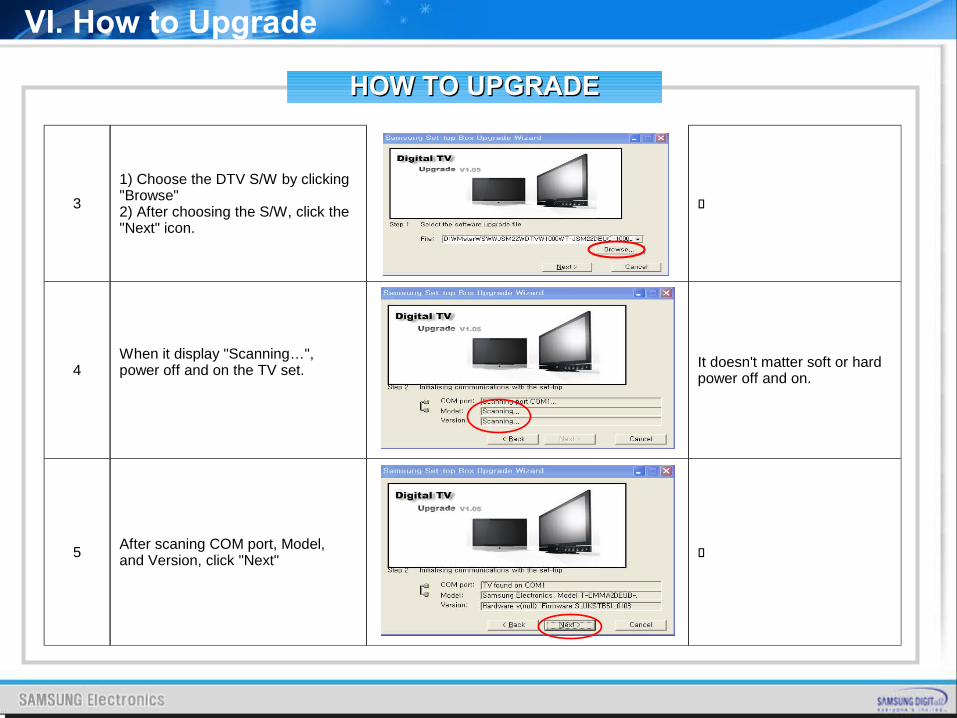
3
1) Choose the DTV S/W by clicking "Browse"2) After choosing the S/W, click the "Next" icon.
4When it display "Scanning…", power off and on the TV set. It doesn't matter soft or hard
power off and on.
5After scaning COM port, Model, and Version, click "Next"
HOW TO UPGRADEHOW TO UPGRADE
After S/W Upgrade
▪ How to Access Service Mode▪ Entering Factory Mode <Power OFF> ☞ <INFO> ☞ <MENU> ☞ <MUTE> ☞ <Power ON>
▪ Factory Data 1. Option Table(Service) 2. WB Adjust 3. Information 4. Advanced Menu If you want to enter here, press “0000”.
VI. How to Upgrade
HOW TO UPGRADEHOW TO UPGRADE
▪ How to Initialize.
Click “1. Option Table(Service)” “Factory Reset” → in Factory Menu. You can make every setting in Factory Initial Status.
VI. How to Upgrade
ATTACHMENT
CONTENTSCONTENTS
I. What is HDMI?
II. What is a TrusurroundXT
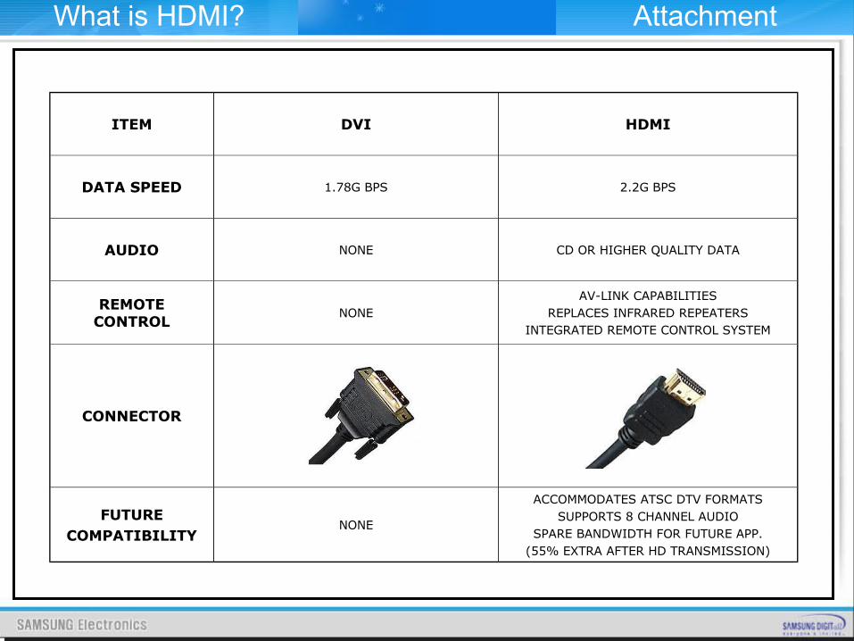
ITEM DVI HDMI
DATA SPEED 1.78G BPS 2.2G BPS
AUDIO NONE CD OR HIGHER QUALITY DATA
REMOTE CONTROL
NONEAV-LINK CAPABILITIES
REPLACES INFRARED REPEATERSINTEGRATED REMOTE CONTROL SYSTEM
CONNECTOR
FUTURECOMPATIBILITY
NONE
ACCOMMODATES ATSC DTV FORMATSSUPPORTS 8 CHANNEL AUDIO
SPARE BANDWIDTH FOR FUTURE APP.(55% EXTRA AFTER HD TRANSMISSION)
What is HDMI? Attachment
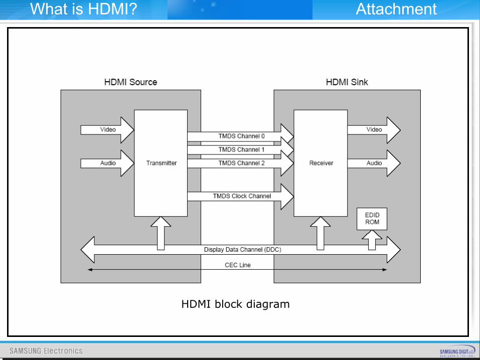
HDMI block diagram
What is HDMI? Attachment
HDMI system architecture is defined to consist of Sources and Sinks. A given device may have one or more HDMI inputs and one or more HDMI outputs. Each HDMI input on these devices shall follow all of the rules for an HDMI Sink and each HDMI output shall follow all of the rules for an HDMI Source.
As shown HDMI block diagram the HDMI cable and connectors carry four differential pairs that make up the TMDS data and clock channels. These channels are used to carry video, audio and auxiliary data. In addition, HDMI carries a VESA DDC channel. The DDC is used for configuration and status exchange between a single Source and a single Sink. The optional CEC protocol provides high-level control functions between all of the various audiovisual products in a user’s environment.
Audio, video and auxiliary data is transmitted across the three TMDS data channels. The video pixel clock is transmitted on the TMDS clock channel and is used by the receiver as a frequency reference for data recovery on the three TMDS data channels. Video data is carried as a series of 24-bit pixels on the three TMDS data channels. TMDS encoding converts the 8 bits per channel into the 10 bit DC-balanced, transition minimized sequence which is then transmitted serially across the pair at a rate of 10 bits per pixel clock period.
What is HDMI? Attachment
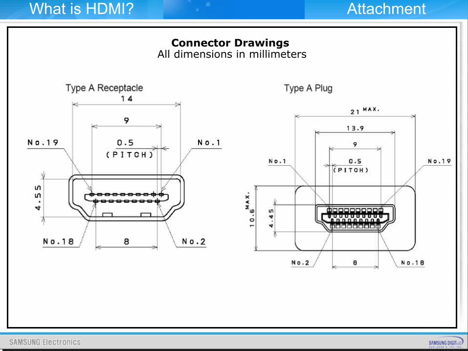
Connector Drawings All dimensions in millimeters
What is HDMI? Attachment
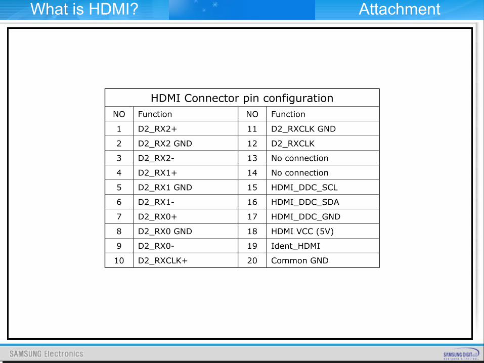
HDMI Connector pin configurationNO Function NO Function
1 D2_RX2+ 11 D2_RXCLK GND
2 D2_RX2 GND 12 D2_RXCLK
3 D2_RX2- 13 No connection
4 D2_RX1+ 14 No connection
5 D2_RX1 GND 15 HDMI_DDC_SCL
6 D2_RX1- 16 HDMI_DDC_SDA
7 D2_RX0+ 17 HDMI_DDC_GND
8 D2_RX0 GND 18 HDMI VCC (5V)
9 D2_RX0- 19 Ident_HDMI
10 D2_RXCLK+ 20 Common GND
What is HDMI? Attachment
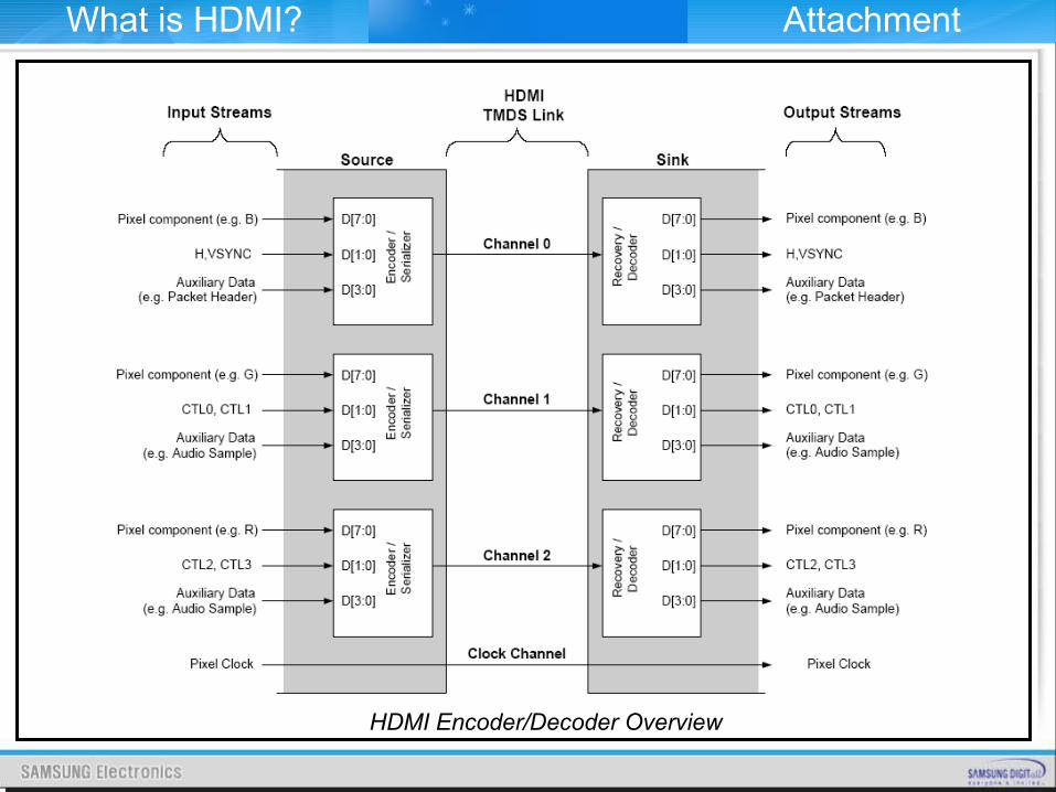
HDMI Encoder/Decoder Overview
What is HDMI? Attachment
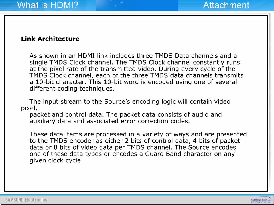
Link Architecture
As shown in an HDMI link includes three TMDS Data channels and a single TMDS Clock channel. The TMDS Clock channel constantly runs at the pixel rate of the transmitted video. During every cycle of the TMDS Clock channel, each of the three TMDS data channels transmits a 10-bit character. This 10-bit word is encoded using one of several different coding techniques.
The input stream to the Source’s encoding logic will contain video pixel, packet and control data. The packet data consists of audio and auxiliary data and associated error correction codes.
These data items are processed in a variety of ways and are presented to the TMDS encoder as either 2 bits of control data, 4 bits of packet data or 8 bits of video data per TMDS channel. The Source encodes one of these data types or encodes a Guard Band character on any given clock cycle.
What is HDMI? Attachment
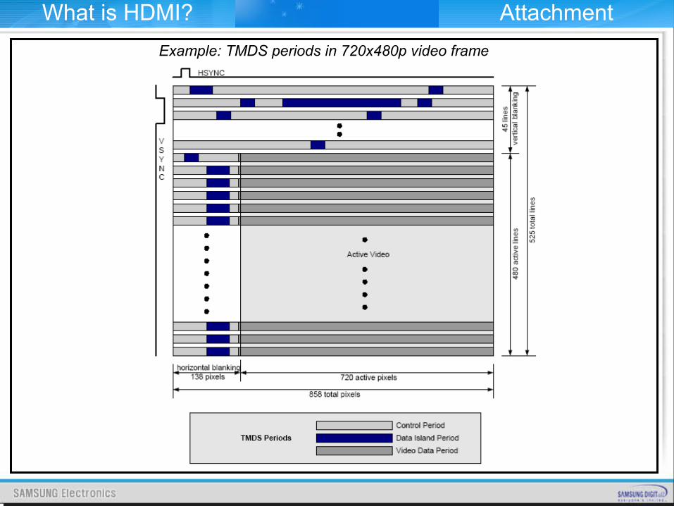
Example: TMDS periods in 720x480p video frame
What is HDMI? Attachment
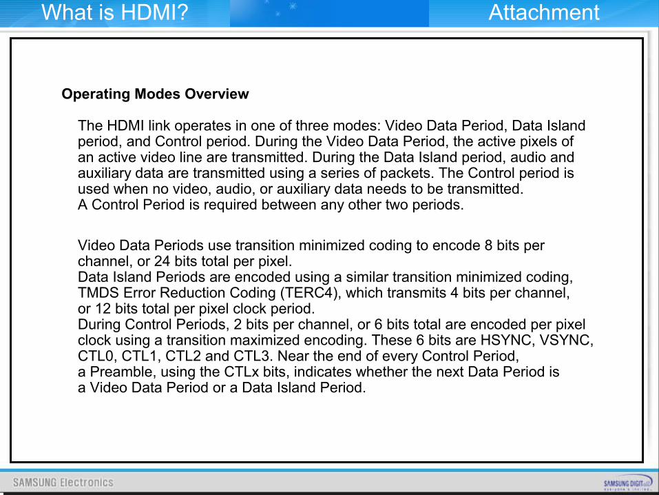
Operating Modes Overview
The HDMI link operates in one of three modes: Video Data Period, Data Island period, and Control period. During the Video Data Period, the active pixels of an active video line are transmitted. During the Data Island period, audio and auxiliary data are transmitted using a series of packets. The Control period is used when no video, audio, or auxiliary data needs to be transmitted. A Control Period is required between any other two periods.
Video Data Periods use transition minimized coding to encode 8 bits per channel, or 24 bits total per pixel. Data Island Periods are encoded using a similar transition minimized coding, TMDS Error Reduction Coding (TERC4), which transmits 4 bits per channel, or 12 bits total per pixel clock period. During Control Periods, 2 bits per channel, or 6 bits total are encoded per pixel clock using a transition maximized encoding. These 6 bits are HSYNC, VSYNC, CTL0, CTL1, CTL2 and CTL3. Near the end of every Control Period, a Preamble, using the CTLx bits, indicates whether the next Data Period is a Video Data Period or a Data Island Period.
What is HDMI? Attachment
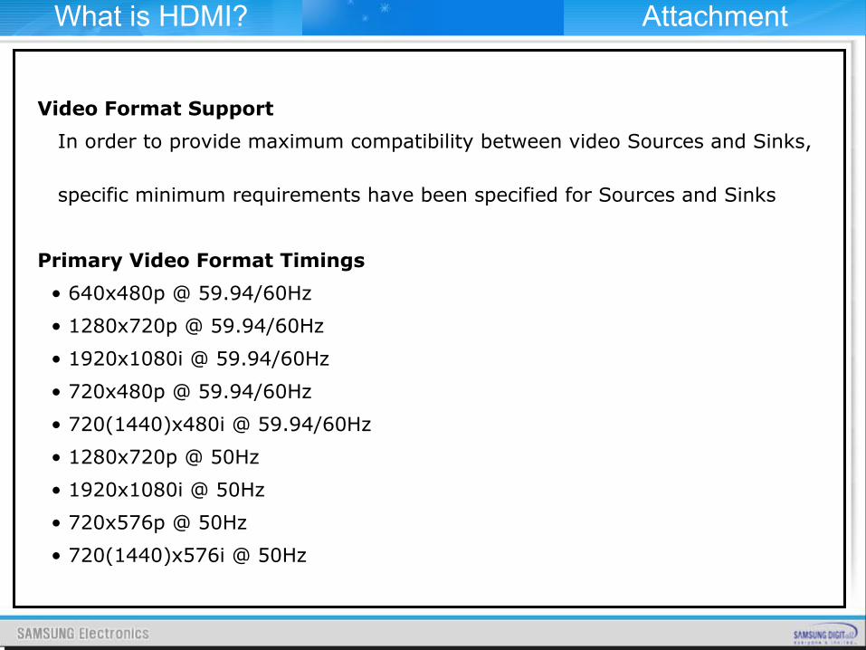
Video Format Support
In order to provide maximum compatibility between video Sources and Sinks,
specific minimum requirements have been specified for Sources and Sinks
Primary Video Format Timings
• 640x480p @ 59.94/60Hz
• 1280x720p @ 59.94/60Hz
• 1920x1080i @ 59.94/60Hz
• 720x480p @ 59.94/60Hz
• 720(1440)x480i @ 59.94/60Hz
• 1280x720p @ 50Hz
• 1920x1080i @ 50Hz
• 720x576p @ 50Hz
• 720(1440)x576i @ 50Hz
What is HDMI? Attachment
Audio Sample Rates and Support Requirements
If an HDMI Source supports audio transmission across any output, then it shall support HDMI audio transmission. If an HDMI Source supports any HDMI audio transmission, then it shall support 2 channel L-PCM using an IEC 60958 Subpacket structure, with either 32kHz, 44.1kHz or 48kHz sampling rate and a sample size of 16 bits or more.
An HDMI Source is permitted to transmit L-PCM or encoded audio data at sample rates of 32kHz, 44.1kHz, 48kHz, 88.2kHz, 96kHz, 176.4kHz and 192kHz using either IEC 60958 format or IEC 61937 format. If an HDMI Sink supports audio reception across any input, then it shall support audio reception from all HDMI inputs.
Basic Audio. is defined as two channel L-PCM audio at sample rates of 32kHz, 44.1kHz, or 48kHz, with a sample size of at least 16 bits. For EIA/CEA-861B references to DTV devices, .Basic Audio. is defined as two channel L-PCM audio at sample rates of 32kHz, 44.1kHz, and 48kHz. There is no sample size usage restriction for DTV devices. An HDMI Sink may optionally accept audio at sample rates of 88.2kHz, 96kHz, 176.4kHz and/or 192kHz using either IEC 60958 format or IEC 61937 format, and should indicate these capabilities in the E-EDID data structure.
What is HDMI? Attachment
Compatibility With DVI
All HDMI Sources shall be compatible with DVI 1.0 compliant sink devices (i.e. “monitors” or “displays”) through the use of a passive cable converter. Likewise, all HDMI Sinks shall be compatible with DVI 1.0 compliant sources (i.e. “systems” or “hosts”) through the use of a similar cable converter.
When communicating with a DVI device, an HDMI device shall operate according to the DVI 1.0 specification, with the following exception - these devices are not required to comply with DVI 1.0 rules regarding:
• Monitor scaling requirements • Physical Interconnect specifications • System Low Pixel Format Support Requirements
Furthermore, for HDMI devices which do not have a “BIOS” or “operating system”, there are the following additional exceptions:
• “BIOS” requirements• “Operating system” requirements • “System level event” requirements• Power management requirements
What is HDMI? Attachment
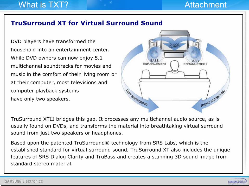
TruSurround XT for Virtual Surround Sound
DVD players have transformed the
household into an entertainment center.
While DVD owners can now enjoy 5.1
multichannel soundtracks for movies and
music in the comfort of their living room or
at their computer, most televisions and
computer playback systems
have only two speakers.
TruSurround XT bridges this gap. It processes any multichannel audio source, as is usually found on DVDs, and transforms the material into breathtaking virtual surround sound from just two speakers or headphones.
Based upon the patented TruSurround® technology from SRS Labs, which is the established standard for virtual surround sound, TruSurround XT also includes the unique features of SRS Dialog Clarity and TruBass and creates a stunning 3D sound image from standard stereo material.
What is TXT? Attachment
TruSurround XT features
� TruSurround: TruSurround is a patented SRS technology that solves the problem of playing 5.1 multichannel content over two speakers. TruSurround delivers a compelling, virtual surround sound experience through any two-speaker playback system, including internal television speakers and headphones. It is fully compatible with all multichannel formats up to 6.1 channels.
� SRS Dialog Clarity Enhancement: Playback of dialog often suffers due to competing signals from other speakers. In addition, feature film soundtracks are mixed specifically for cinema playback and are loaded with the latest advancements in special audio effects. When translated over home theatre or computers systems, dialog may become unintelligible. This patented SRS algorithm enhances signal clarity to address these problems, thus improving dialog intelligibility from all such source material.
What is TXT? Attachment
TruSurround XT features
� TruBass: TruBass is a patented SRS technology that enhances bass performance utilizing proprietary psychoacoustic techniques. These techniques restore the perception of fundamental low frequency tones by dynamically augmenting harmonics, which are more easily reproduced by contemporary loudspeakers.
Using TruBass, TruSurround XT takes the bass information contained within the original audio track and helps the speakers or headphones re-create it – even if it is below the speaker’s low frequency limitations.
� WOW: WOW™ is an award winning stereo enhancement technology that significantly improves the performance of stereo (non-surround sound encoded material) signals through any two-speaker system, including headphones. It extends the sound image in both the horizontal and vertical planes well beyond the speakers themselves. In addition, WOW incorporates TruBass and SRS Dialog Clarity Enhancement.
When TruSurround XT accepts a stereo signal, WOW is enabled for a better listening experience. Wow is also used by Microsoft in their new Media Player for Windows XP and Windows Media Player 7.
What is TXT? Attachment