lcls-ii vacuum design and manufacturingslac.stanford.edu/pubs/slacpubs/16750/slac-pub-16975.pdf ·...
TRANSCRIPT
LCLS-II Vacuum Design and
Manufacturing
G. Lanza, D. Gill, L. Young, S. Saraf
SLAC National Accelerator Laboratory
OLAV, May 9th 2017
Guidelines and an Approach to Implementation
Work described in this presentation is supported by the U.S. Department of Energy, Office of Science, under Contract No. DE-AC02-76SF00515.
Doc. N. SLAC-PUB-16975

2
Overview
1. LCLS-II Project Background
2. Vacuum Systems and Challenges
3. Beam line vacuum
- Design
- Manufacturing
• UHV
• Particle Free
4. Beamline Failure Mode Analysis

3
LCLS-II project
….
LCLS-II DOE Review, Oct 12-14, 2016
Slide 3
LCLS-II
New Injector and
New Superconducting Linac
Existing Bypass Line
New Transport Line Two New Undulators
And X-Ray Transport
Exploit Existing
Experimental Stations
New Cryoplant
Sector 0 Sector 10 Sector 20 Sector 30
0 500 1000 1500 2000 2500 3000 3500
Extension lineBypass line
LCLS-I
Bypass BSY LTU EBD
Undulators
SXU
HXUL1 L2 L3
SRF Cryomodules (L0, L1, L2, L3)
joined by warm beamline sections
Z (m)
crossover
Beam SpreaderDogleg
m wall
Cryoplant & cryo distribution
Injector & L0
Dumps
Proposed FACET II
FEE
End Stations
4
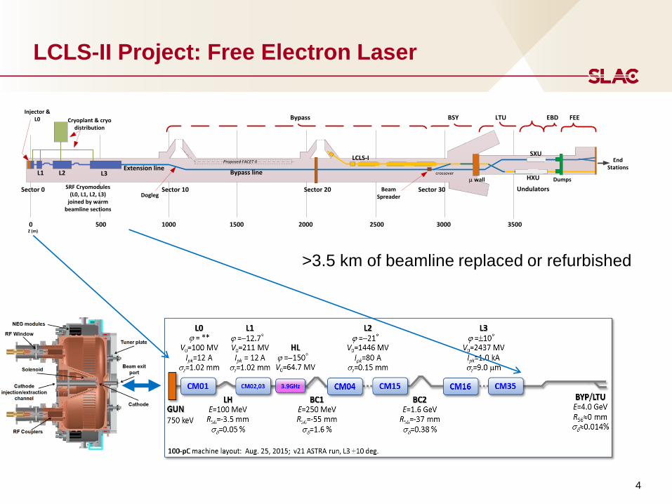
LCLS-II Project: Free Electron Laser
>3.5 km of beamline replaced or refurbished
Helium (2.2K )
Cryo Distribution Insulating Vacuum
Beamline Vacuum
RF Coupler Vacuum
To Cryo Distribution
Cryo Module
2.2K
45K
300K
Vacuum wall
Cryo Module Insulating Vacuum
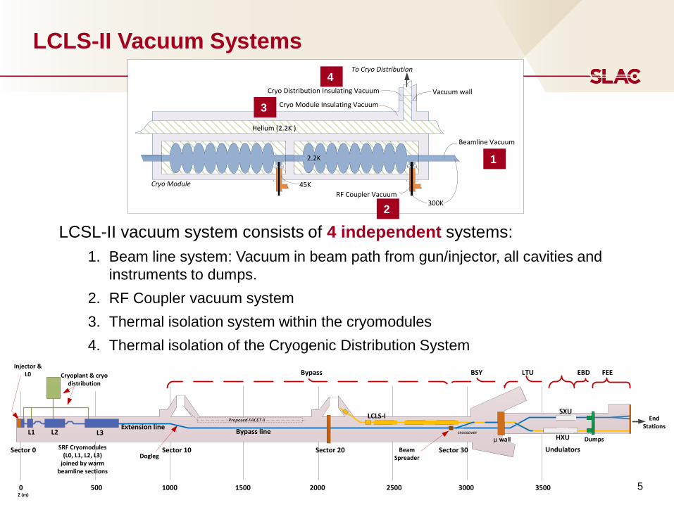
LCLS-II Vacuum Systems
LCSL-II vacuum system consists of 4 independent systems:
1. Beam line system: Vacuum in beam path from gun/injector, all cavities and
instruments to dumps.
2. RF Coupler vacuum system
3. Thermal isolation system within the cryomodules
4. Thermal isolation of the Cryogenic Distribution System
Sector 0 Sector 10 Sector 20 Sector 30
0 500 1000 1500 2000 2500 3000 3500
Extension lineBypass line
LCLS-I
Bypass BSY LTU EBD
Undulators
SXU
HXUL1 L2 L3
SRF Cryomodules (L0, L1, L2, L3)
joined by warm beamline sections
Z (m)
crossover
Beam SpreaderDogleg
m wall
Cryoplant & cryo distribution
Injector & L0
Dumps
Proposed FACET II
FEE
End Stations
1
2
3
4
5

LCLS-II Vacuum Systems
LCSL-II Vacuum System is comprised of multiple environmental conditions:
• Ambient temperature, UHV pressure (most of downstream beamline)
• Ambient temperature, UHV pressure, particle-free (between cryomodules)
• Cryo temperature, UHV, particle-free (cryomodules)
• Cryo temperature, high vacuum (insulating vacuum)
Sector 0 Sector 10 Sector 20 Sector 30
0 500 1000 1500 2000 2500 3000 3500
Extension lineBypass line
LCLS-I
Bypass BSY LTU EBD
Undulators
SXU
HXUL1 L2 L3
SRF Cryomodules (L0, L1, L2, L3)
joined by warm beamline sections
Z (m)
crossover
Beam SpreaderDogleg
m wall
Cryoplant & cryo distribution
Injector & L0
Dumps
Proposed FACET II
FEE
End Stations
6
Helium (2.2K )
Cryo Distribution Insulating Vacuum
Beamline Vacuum
RF Coupler Vacuum
To Cryo Distribution
Cryo Module
2.2K
45K
300K
Vacuum wall
Cryo Module Insulating Vacuum
1
2
3
4
7
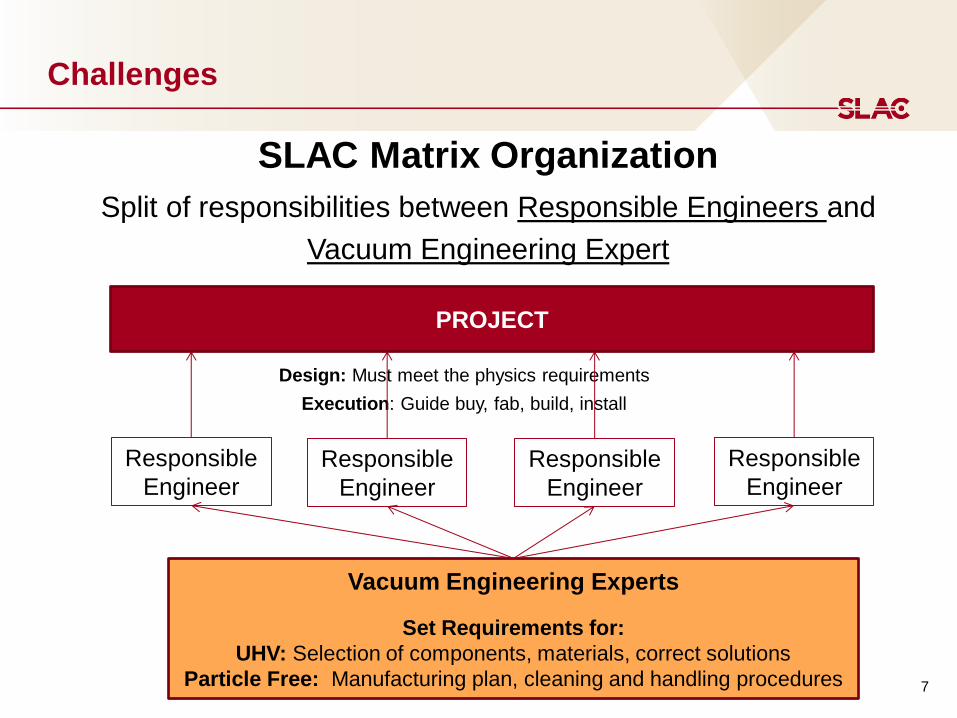
Challenges
Design: Must meet the physics requirements
Execution: Guide buy, fab, build, install
SLAC Matrix Organization
Split of responsibilities between Responsible Engineers and
Vacuum Engineering Expert
Responsible
Engineer
Responsible
Engineer Responsible
Engineer
Responsible
Engineer
PROJECT
Vacuum Engineering Experts
Set Requirements for:
UHV: Selection of components, materials, correct solutions
Particle Free: Manufacturing plan, cleaning and handling procedures
BEAM LINE VACUUM SYSTEM:
DESIGN
9
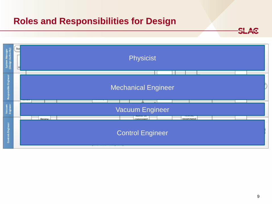
Roles and Responsibilities for Design
Physicist
Mechanical Engineer
Vacuum Engineer
Control Engineer

10
Roles and Responsibilities for Design
• High level requirements are defined by physics.
• Vacuum Engineering converts to Vacuum Specifications
• Mechanical Engineering converts specs to design
• Control Engineer implement the system logic and protection
11
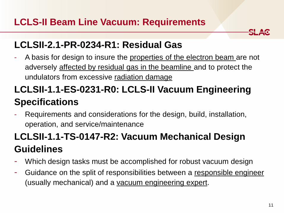
LCLS-II Beam Line Vacuum: Requirements
LCLSII-2.1-PR-0234-R1: Residual Gas
- A basis for design to insure the properties of the electron beam are not
adversely affected by residual gas in the beamline and to protect the
undulators from excessive radiation damage
LCLSII-1.1-ES-0231-R0: LCLS-II Vacuum Engineering
Specifications
- Requirements and considerations for the design, build, installation,
operation, and service/maintenance
LCLSII-1.1-TS-0147-R2: Vacuum Mechanical Design
Guidelines
- Which design tasks must be accomplished for robust vacuum design
- Guidance on the split of responsibilities between a responsible engineer
(usually mechanical) and a vacuum engineering expert.

12
Vacuum Requirements
Table 7.1, Vacuum ESD, LCLSII-1.1-ES-0231, rev. 1 (page 1)
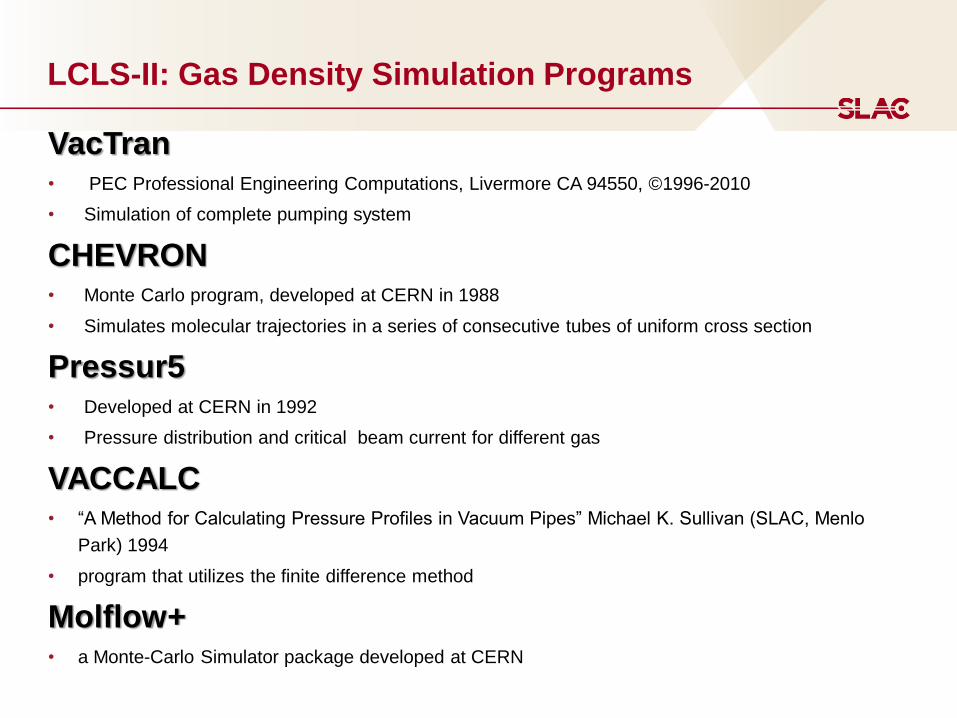
VacTran • PEC Professional Engineering Computations, Livermore CA 94550, ©1996-2010
• Simulation of complete pumping system
CHEVRON • Monte Carlo program, developed at CERN in 1988
• Simulates molecular trajectories in a series of consecutive tubes of uniform cross section
Pressur5 • Developed at CERN in 1992
• Pressure distribution and critical beam current for different gas
VACCALC
• “A Method for Calculating Pressure Profiles in Vacuum Pipes” Michael K. Sullivan (SLAC, Menlo
Park) 1994
• program that utilizes the finite difference method
Molflow+ • a Monte-Carlo Simulator package developed at CERN
LCLS-II: Gas Density Simulation Programs
14
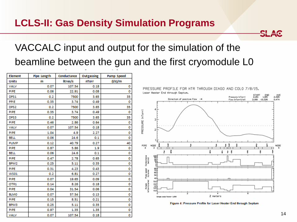
LCLS-II: Gas Density Simulation Programs
VACCALC input and output for the simulation of the
beamline between the gun and the first cryomodule L0
15
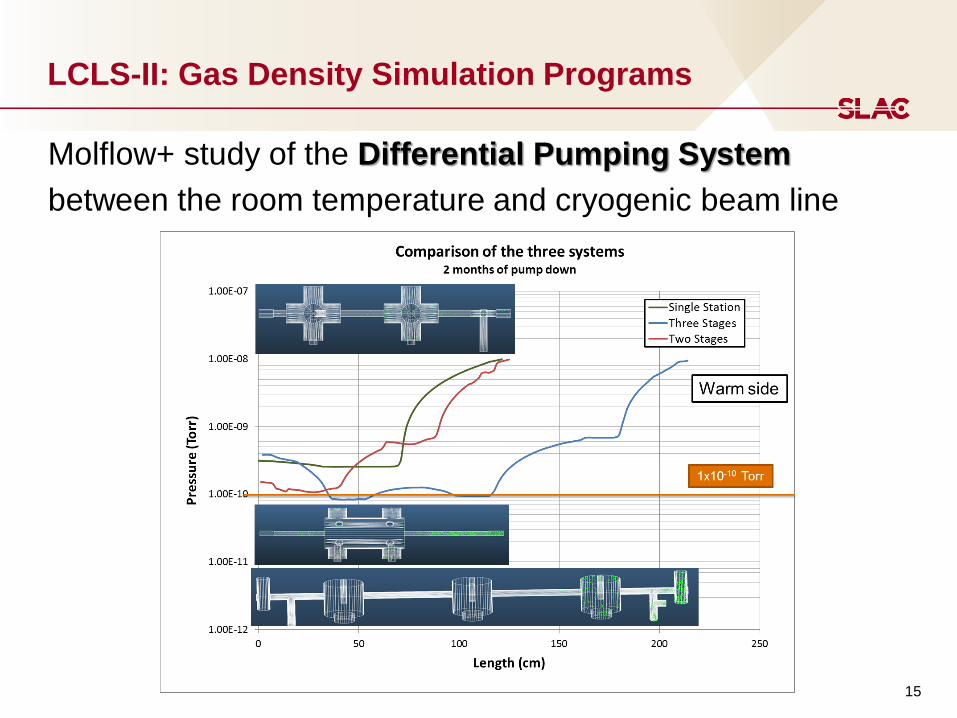
LCLS-II: Gas Density Simulation Programs
Molflow+ study of the Differential Pumping System
between the room temperature and cryogenic beam line
Sector 0 Sector 10 Sector 20 Sector 30
0 500 1000 1500 2000 2500 3000 3500
Extension lineBypass line
LCLS-I
Bypass BSY LTU EBD
Undulators
SXU
HXUL1 L2 L3
SRF Cryomodules (L0, L1, L2, L3)
joined by warm beamline sections
Z (m)
crossover
Beam SpreaderDogleg
m wall
Cryoplant & cryo distribution
Injector & L0
Dumps
Proposed FACET II
FEE
End Stations
16
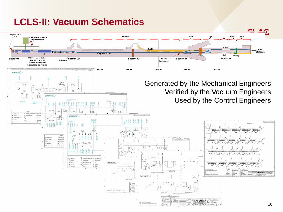
LCLS-II: Vacuum Schematics
Generated by the Mechanical Engineers
Verified by the Vacuum Engineers
Used by the Control Engineers
BEAM LINE VACUUM SYSTEM:
SLAC MANUFACTURING - UHV REQUIREMENTS
18
SLAC UHV Acceptance Test Criteria
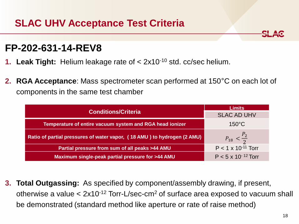
FP-202-631-14-REV8
1. Leak Tight: Helium leakage rate of < 2x10⁻¹⁰ std. cc/sec helium.
2. RGA Acceptance: Mass spectrometer scan performed at 150°C on each lot of
components in the same test chamber
3. Total Outgassing: As specified by component/assembly drawing, if present,
otherwise a value < 2x10-12 Torr-L/sec-cm2 of surface area exposed to vacuum shall
be demonstrated (standard method like aperture or rate of raise method)
Conditions/Criteria Limits
SLAC AD UHV
Temperature of entire vacuum system and RGA head ionizer 150°C
Ratio of partial pressures of water vapor, ( 18 AMU ) to hydrogen (2 AMU) 𝑃18 <𝑃2
2
Partial pressure from sum of all peaks >44 AMU P < 1 x 10-11 Torr
Maximum single-peak partial pressure for >44 AMU P < 5 x 10- 12 Torr
19
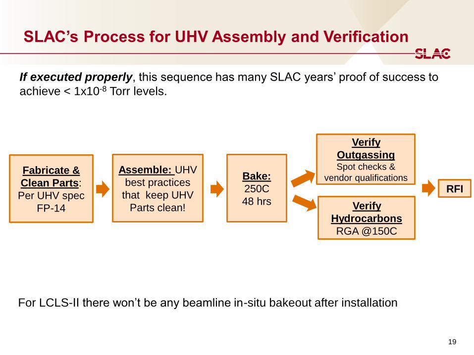
SLAC’s Process for UHV Assembly and Verification
Fabricate &
Clean Parts:
Per UHV spec
FP-14
Assemble: UHV
best practices
that keep UHV
Parts clean!
Bake:
250C
48 hrs
Verify
Outgassing Spot checks &
vendor qualifications
Verify
Hydrocarbons
RGA @150C
If executed properly, this sequence has many SLAC years’ proof of success to
achieve < 1x10⁻⁸ Torr levels.
RFI
For LCLS-II there won’t be any beamline in-situ bakeout after installation
BEAM LINE VACUUM SYSTEM:
SLAC MANUFACTURING - PARTICLE FREE REQUIREMENTS
21
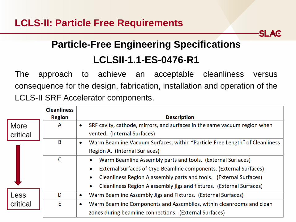
LCLS-II: Particle Free Requirements
Particle-Free Engineering Specifications
LCLSII-1.1-ES-0476-R1
The approach to achieve an acceptable cleanliness versus
consequence for the design, fabrication, installation and operation of the
LCLS-II SRF Accelerator components.
More
critical
Less
critical

22
LCLS-II: Particle Free Requirements
Graded
approach
23
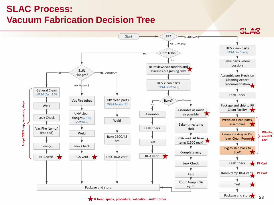
SLAC Process:
Vacuum Fabrication Decision Tree
= Need specs, procedure, validation, and/or other
Start PF?
Drift Tube?
Bake?
Assemble
Test
UHV clean parts (FP14, Section 3)
Leak Check
RGA verif.
Assemble as much as possible
Bake (time/temp tbd)
RGA verif. At bake temp (150C max)
Complete assy
Leak Check
Test
Room temp RGA verif.
RE reviews vac models and assesses outgassing risks
Package and store
No (UHV only)
No
Yes
Yes
No
Yes (UHV/PF)
DE
316L Flanges?
General Clean(FP14, Sect 2.D)
Weld
Leak Check
RGA verif.
UHV clean flanges (FP14,
Section 3)
UHV clean parts (FP14,Section 3)
Vac Fire (temp/time tbd)
Clean(?)
Vac Fire tubes
Weld
Leak Check
RGA verif.
Weld
Bake 250C/48 hrs
150C RGA verif.
No, Option B
Yes No, Option C
A
B C
Ad
op
t C
ERN
re
qs,
se
qu
en
ce, s
tep
s
UHV clean parts (FP14, Section 3)
Bake parts where possible
Assemble per Precision Cleaning expert
recommendation
Leak Check
Leak Check
Room temp RGA verif.
Test
Package and ship to PF Clean Facility
Precision clean parts, assemblies
Complete Assy in PF-level Clean Room
Pkg to ship back to SLAC
Package and store
PF Cart
PF Cart
Off-site, need PF Cart
F
24
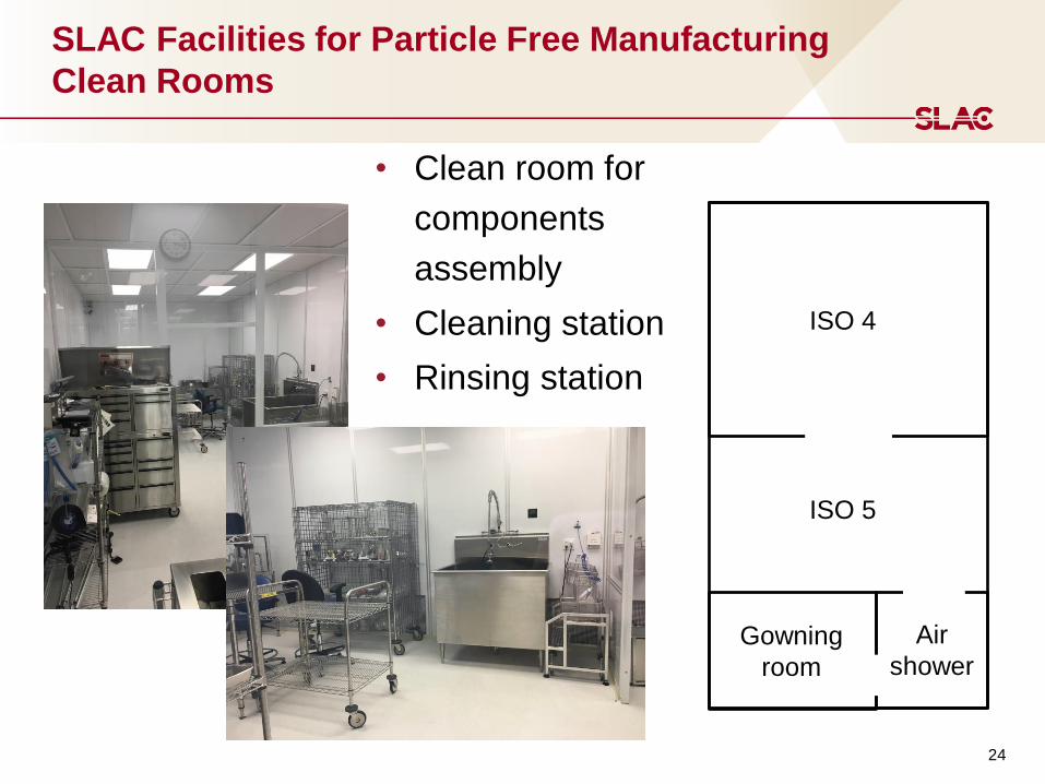
SLAC Facilities for Particle Free Manufacturing
Clean Rooms
ISO 4
ISO 5
Air
shower Gowning
room
• Clean room for
components
assembly
• Cleaning station
• Rinsing station

25
LCLS-II: Particle Free Pump Cart
• LCLS-II installation Particle Free zones:
• Venting
• Pumping
• Leak detection
• Prior to installation, every component
designated for the LCLS-II Particle Free zone
will be pumped and tested with the Particle
Free cart, following specific procedures
• For pumping and venting the Mass Flow
Controller is set up at 3 lN/min (40 Torr l/s)
Reference:
• “Particle Free Pump Down and Venting of UHV Vacuum
Systems” by K. Zapfe and J. Wojtkiewicz, SRF2007
26
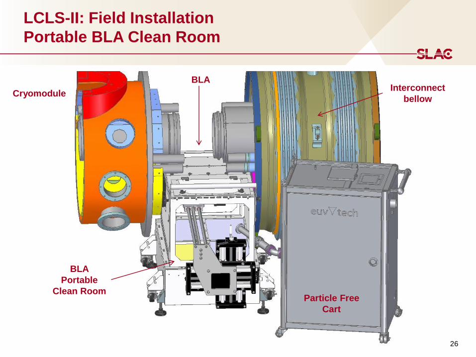
LCLS-II: Field Installation
Portable BLA Clean Room
BLA
BLA
Portable
Clean Room Particle Free
Cart
Cryomodule Interconnect
bellow

27
LCLS-II: Field Installation
Portable Overhead Clean Room
Used for
interconnection of the
room temperature
beam line
BEAM LINE VACUUM SYSTEM:
FAILURE ANALYSIS
29
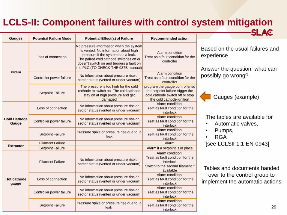
LCLS-II: Component failures with control system mitigation
Gauges (example)
The tables are available for
• Automatic valves,
• Pumps,
• RGA
[see LCLSII-1.1-EN-0943]
Gauges Potential Failure Mode Potential Effect(s) of Failure Recommended action
Pirani
loss of connection
No pressure information when the system
is vented. No information about high
pressure if the system has a leak.
The paired cold cathode switches off or
doesn't switch on and triggers a fault on
the PLC (TO CHECK THE 937B manual)
Alarm condition
Treat as a fault condition for the
controller
Controller power failure No information about pressure rise or
sector status (vented or under vacuum)
Alarm condition
Treat as a fault condition for the
controller
Setpoint Failure
The pressure is too high for the cold
cathode to switch on. The cold cathode
stay on at high pressure and get
damaged
program the gauge controller so
the setpoint failure trigger the
cold cathode switch off or stop
the cold cathode ignition
Cold Cathode
Gauge
Loss of connection No information about pressure rise or
sector status (vented or under vacuum)
Alarm condition,
Treat as fault condition for the
interlock
Controller power failure No information about pressure rise or
sector status (vented or under vacuum)
Alarm condition,
Treat as fault condition for the
interlock
Setpoint Failure Pressure spike or pressure rise due to a
leak
Alarm condition,
Treat as fault condition for the
interlock
Extractor Filament Failure Alarm
Setpoint Failure Alarm if a setpoint is in place
Hot cathode
gauge
Filament Failure No information about pressure rise or
sector status (vented or under vacuum)
Alarm condition,
Treat as fault condition for the
interlock
Switch to the second filament if
available
Loss of connection No information about pressure rise or
sector status (vented or under vacuum)
Alarm condition,
Treat as fault condition for the
interlock
Controller power failure No information about pressure rise or
sector status (vented or under vacuum)
Alarm condition,
Treat as fault condition for the
interlock
Setpoint Failure Pressure spike or pressure rise due to a
leak
Alarm condition,
Treat as fault condition for the
interlock
Based on the usual failures and
experience
Answer the question: what can
possibly go wrong?
Tables and documents handed
over to the control group to
implement the automatic actions

30
LCLS-II: Alerts and automatic actions: rules and logic (1)
The logic of the operating system for gate valves
General Rules:
• Interlock sensors are Pirani, Cold Cathode gauges and Ion pumps
- Reliable pressure measurement in the range we use them
- More tolerant of high pressure than filament gauges
• Hot Filament Ion gauge are used for interlock only when there is no other choice (CC
or IP) available
- The filament is sensitive to sudden pressure variation
• The Particle Free (PF) area has an interlock redundancy, coincidence detection of at
least 2 of 3
- To make sure the gate valves don’t close due to electric glitch
• Each PF sector has at least two interlock sensors per sector
- If the sector is vented two of three sensors will be interlocking the gate valves to
stay close
• Each triplet closes the two valves of the sector
- The problem arising in one sector will stay confined in that sector
• Fast shutters are triggered by coincidence of two cold cathode gauges
31
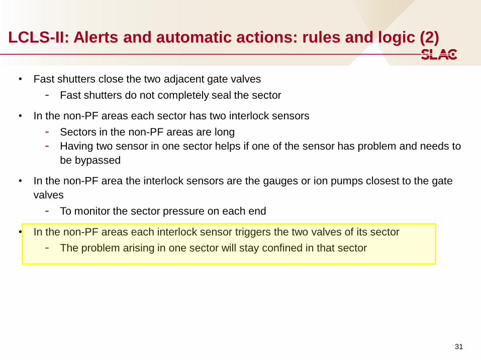
LCLS-II: Alerts and automatic actions: rules and logic (2)
• Fast shutters close the two adjacent gate valves
- Fast shutters do not completely seal the sector
• In the non-PF areas each sector has two interlock sensors
- Sectors in the non-PF areas are long
- Having two sensor in one sector helps if one of the sensor has problem and needs to
be bypassed
• In the non-PF area the interlock sensors are the gauges or ion pumps closest to the gate
valves
- To monitor the sector pressure on each end
• In the non-PF areas each interlock sensor triggers the two valves of its sector
- The problem arising in one sector will stay confined in that sector
32
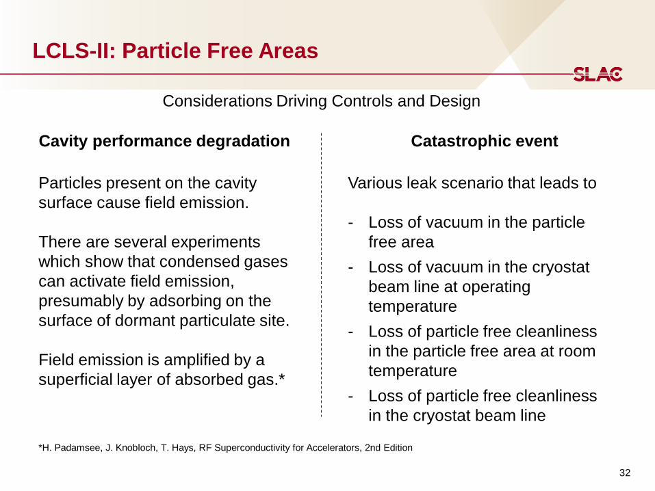
LCLS-II: Particle Free Areas
Cavity performance degradation Catastrophic event
Particles present on the cavity
surface cause field emission.
There are several experiments
which show that condensed gases
can activate field emission,
presumably by adsorbing on the
surface of dormant particulate site.
Field emission is amplified by a
superficial layer of absorbed gas.*
*H. Padamsee, J. Knobloch, T. Hays, RF Superconductivity for Accelerators, 2nd Edition
Various leak scenario that leads to
- Loss of vacuum in the particle
free area
- Loss of vacuum in the cryostat
beam line at operating
temperature
- Loss of particle free cleanliness
in the particle free area at room
temperature
- Loss of particle free cleanliness
in the cryostat beam line
Considerations Driving Controls and Design
33
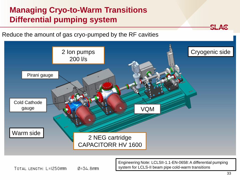
Managing Cryo-to-Warm Transitions
Differential pumping system
Warm side
Cryogenic side
2 NEG cartridge
CAPACITORR HV 1600
2 Ion pumps
200 l/s
Cold Cathode
gauge
Pirani gauge
VQM
Total length: L=1250mm =mm Engineering Note: LCLSII-1.1-EN-0658: A differential pumping
system for LCLS-II beam pipe cold-warm transitions
Reduce the amount of gas cryo-pumped by the RF cavities

34
Managing Cryo-to-Warm Transitions:
Example of leak in BC2B
Moving parts –
weak point for
possible leak
Gate valves close
Interlock 1.
2.
3.
Fast shutter closes
Fast shutters are intended to limit the propagation of acoustic shock waves, such as
from a thin window break or accidental opening of an isolation valve to a vented volume

Summary
36
LCLS-II Project`
LCLS-II beam line design is completed
To support the mechanical engineers in their work the vacuum group set
the new SLAC standards for:
• design and manufacture UHV vacuum system
• Test and accept the UHV components
• clean for particle free
The effort for preparing the infrastructures (bakeout stations, clean
rooms, pumping carts, …) to accommodate the LCLS-II incoming
activities is ongoing.
Next Steps:
- Test/validate the external companies
- Train our technicians for clean room work
END
Thank you