lcv3, lcv4, lcv6 and lcv7 lift check valves
TRANSCRIPT

IM-P029-17 CMGT Issue 6 1
LCV3, LCV4, LCV6 and LCV7 Lift Check Valves
0290050/6
LCV3, LCV4, LCV6 and LCV7 Lift Check Valves
Installation and Maintenance Instructions
IM-P029-17CMGT Issue 6
1. Safety information
2. General product information
3. Installation
4. Commissioning
5. Operation
6. Spare parts and Maintenance
© Copyright 2021
Printed in GB

IM-P029-17 CMGT Issue 62
LCV3, LCV4, LCV6 and LCV7 Lift Check Valves
Safe operation of these products can only be guaranteed if they are properly installed, commissioned, used and maintained by qualified personnel (see Section 1.11) in compliance with the operating instructions. General installation and safety instructions for pipeline and plant construction, as well as the proper use of tools and safety equipment must also be complied with.
1.1 Intended useReferring to the Installation and Maintenance Instructions, name-plate and Technical Information Sheet, check that the product is suitable for the intended use/application. The products listed below comply with the requirements of the EU Pressure Equipment Directive/UK Pressure
Equipment (Safety) Regulations and carry the mark when so required. It should be noted
that products rated as 'SEP' are required by the Directive not to carry the mark.
The products fall within the following Pressure Equipment Directive categories:
Unit Sizes Connections Group 1Gases
Group 2Gases
Group 1Liquids
Group 2Liquids
LCV3
DN15 to DN25 All SEP SEP SEP SEP
DN32 to DN50 All 1 SEP SEP SEP
DN65 to DN100 All 2 1 SEP SEP
LCV4
DN15 to DN25 All SEP SEP SEP SEP
DN32 All 2 SEP SEP SEP
DN40 to DN50
ASME 1501 SEP SEP SEP
JIS/KS 10
PN25 and PN402 1 SEP SEP
JIS/KS 20
Others 2 1 2 SEP
DN65 to DN100 All 2 1 2 SEP
LCV6
DN15 to DN25 All SEP SEP SEP SEP
DN32 All 2 SEP SEP SEP
DN40 to DN50
ASME 1501 SEP SEP SEP
JIS/KS 10
BSP
2 1 SEP SEPPN16, PN25 and PN40
JIS/KS 20
Others 2 1 2 SEP
DN65 to DN100 All SEP 1 2 SEP
1. Safety information

IM-P029-17 CMGT Issue 6 3
LCV3, LCV4, LCV6 and LCV7 Lift Check Valves
Unit Sizes Connections Group 1Gases
Group 2Gases
Group 1Liquids
Group 2Liquids
LCV7
DN15 to DN25 All SEP SEP SEP SEP
DN32 to DN40
ASME 2502 1 SEP SEP
NPT
Others 1 SEP SEP SEP
DN50 to DN65
ASME 1251 SEP SEP SEP
JIS/KS 10
Others 2 1 SEP SEP
DN80ASME 250 2 1 2 SEP
Others 2 1 SEP SEP
DN100
ASME 125
2 1 SEP SEPPN16
JIS/KS 10
Others 2 1 2 SEP
i) These products have been specifically designed for use on steam, air or water/condensate as stated in Groups 1 and 2 of the above mentioned Pressure Equipment Directive. The products’ use on other fluids may be possible but, if this is contemplated, Spirax Sarco should be contacted to confirm the suitability of the product for the application being considered.
ii) Check material suitability, pressure and temperature and their maximum and minimum values. If the maximum operating limits of the product are lower than those of the system in which it is being fitted, or if malfunction of the product could result in a dangerous overpressure or overtemperature occurrence, ensure a safety device is included in the system to prevent such over-limit situations.
iii) Determine the correct installation situation and direction of fluid flow.
iv) Spirax Sarco products are not intended to withstand external stresses that may be induced by any system to which they are fitted. It is the responsibility of the installer to consider these stresses and take adequate precautions to minimise them.
v) Remove protection covers from all connections and protective film from all name-plates, where appropriate, before installation on steam or other high temperature applications.
1.2 AccessEnsure safe access and if necessary a safe working platform (suitably guarded) before attempting to work on the product. Arrange suitable lifting gear if required.
1.3 LightingEnsure adequate lighting, particularly where detailed or intricate work is required.

IM-P029-17 CMGT Issue 64
LCV3, LCV4, LCV6 and LCV7 Lift Check Valves
1.4 Hazardous liquids or gases in the pipelineConsider what is in the pipeline or what may have been in the pipeline at some previous time. Consider: flammable materials, substances hazardous to health, extremes of temperature.
1.5 Hazardous environment around the productConsider: explosion risk areas, lack of oxygen (e.g. tanks, pits), dangerous gases, extremes of temperature, hot surfaces, fire hazard (e.g. during welding), excessive noise, moving machinery.
1.6 IsolationConsider the effect on the complete system of the work proposed. Will any proposed action (e.g. closing isolation valves, electrical isolation) put any other part of the system or any personnel at risk? Dangers might include isolation of vents or protective devices or the rendering ineffective of controls or alarms. Ensure isolation valves are turned on and off in a gradual way to avoid system shocks.
1.7 Pressure Before attempting any maintenance consider what is or may have been in the pipeline. Ensure that any pressure is isolated and safely vented to atmospheric pressure before attempting to maintain the product, this is easily achieved by fitting Spirax Sarco depressurisation valves type DV (see separate literature for details) and consider double isolation (double block and bleed) and the locking or labelling of closed valves. Do not assume that the system is depressurised even when a pressure gauge indicates zero.
1.8 TemperatureAllow time for temperature to normalise after isolation to avoid the danger of burns and consider whether protective clothing (including safety glasses) is required.
1.9 Tools and consumablesBefore starting work ensure that you have suitable tools and/or consumables available. Use only genuine Spirax Sarco replacement parts.
1.10 Protective clothingConsider whether you and/or others in the vicinity require any protective clothing to protect against the hazards of, for example, chemicals, high/low temperature, radiation, noise, falling objects, and dangers to eyes and face.
1.11 Permits to workAll work must be carried out or be supervised by a suitably competent person.Installation and operating personnel should be trained in the correct use of the product according to the Installation and Maintenance Instructions.Where a formal 'permit to work' system is in force it must be complied with. Where there is no such system, it is recommended that a responsible person should know what work is going on and, where necessary, arrange to have an assistant whose primary responsibility is safety.Post 'warning notices' if necessary.

IM-P029-17 CMGT Issue 6 5
LCV3, LCV4, LCV6 and LCV7 Lift Check Valves
1.12 HandlingManual handling of large and/or heavy products may present a risk of injury. Lifting, pushing, pulling, carrying or supporting a load by bodily force can cause injury particularly to the back. You are advised to assess the risks taking into account the task, the individual, the load and the working environment and use the appropriate handling method depending on the circumstances of the work being done.
1.13 Residual hazardsIn normal use the external surface of the product may be very hot. If used at the maximum permitted operating conditions the surface temperature of some products may reach temperatures of 400 °C (752 °F).Many products are not self-draining. Take due care when dismantling or removing the product from an installation (refer to 'Maintenance instructions').
1.14 FreezingProvision must be made to protect products which are not self-draining against frost damage in environments where they may be exposed to temperatures below freezing point.
1.15 DisposalUnless otherwise stated in the Installation and Maintenance Instructions, these products are recyclable and no ecological hazard is anticipated with their disposal providing due care is taken.
1.16 Returning productsCustomers and stockists are reminded that under EC Health, Safety and Environment Law, when returning products to Spirax Sarco they must provide information on any hazards and the precautions to be taken due to contamination residues or mechanical damage which may present a health, safety or environmental risk. This information must be provided in writing including Health and Safety data sheets relating to any substances identified as hazardous or potentially hazardous.
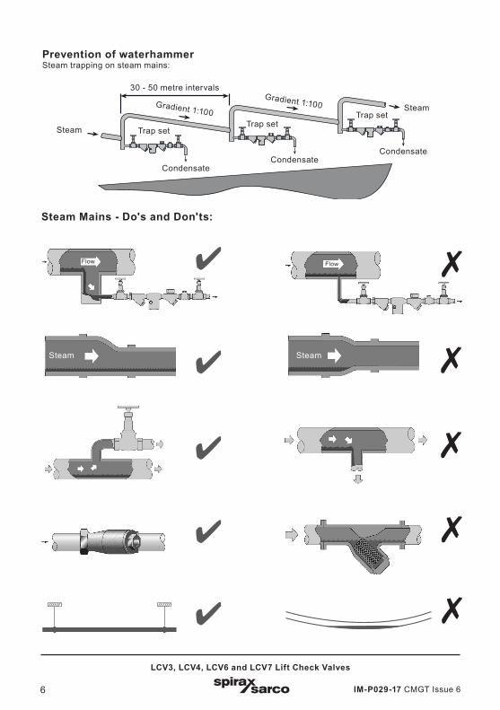
1.17 Working safely with cast iron products on steamCast iron products are commonly found on steam and condensate systems. If installed correctly using good steam engineering practices, it is perfectly safe. However, because of its mechanical properties, it is less forgiving compared to other materials such as SG iron or carbon steel. The following are the good engineering practices required to prevent waterhammer and ensure safe working conditions on a steam system.
Safe HandlingCast Iron is a brittle material. If the product is dropped during installation and there is any risk of damage the product should not be used unless it is fully inspected and pressure tested by the manufacturer.
IM-P029-17 CMGT Issue 66
LCV3, LCV4, LCV6 and LCV7 Lift Check Valves
Prevention of waterhammer Steam trapping on steam mains:
Steam Mains - Do's and Don'ts:
Steam Steam
Flow Flow
30 - 50 metre intervalsGradient 1:100Gradient 1:100
Trap setTrap set
Trap set
CondensateCondensate
Condensate
Steam
Steam

IM-P029-17 CMGT Issue 6 7
LCV3, LCV4, LCV6 and LCV7 Lift Check Valves
Prevention of tensile stressing Pipe misalignment:
Installing products or re-assembling after maintenance:
Thermal expansion:
Do not over tighten.Use correct torque figures.
11
4 2
3
82
6
3
7
Flange bolts should be gradually tightened across diameters to ensure even load and alignment.
Guides
Guides
Limit rods
Limit rods
Fixing pointMedium distance
Small lateral
movement
Small lateral movement
Large lateral movement
Large lateral movement
Short distance Fixing point
Axial movement
Axial movement
Guides
Guides
5
4

IM-P029-17 CMGT Issue 68
LCV3, LCV4, LCV6 and LCV7 Lift Check Valves
2.1 General descriptionThe LCV3, LCV4, LCV6 and LCV7 lift check valves are designed in accordance withEN 12516 and ASME B16.34 to prevent reverse flow in the installations.
Available types:LCV3 Cast iron bodied with stainless steel internals.LCV4 Cast steel bodied with stainless steel internals.LCV6 Stainless steel bodied with stainless steel internals.LCV7 SG iron bodied with stainless steel internals.
Optional for the LCV4:High temperature bolting (stainless steel A2-80).
StandardsThese products fully comply with the requirements of the EU Pressure Equipment Directive/UK Pressure
Equipment (Safety) Regulations and carries the mark when so required.
Standard shut-offThis range of lift check valves conform to EN 12266-1: 2003 Rate F.
CertificationWith the exception of the LCV3 these products are available with certification to EN 10204 3.1. Note: All certification/inspection requirements must be stated at the time of order placement.
Note: For further information see the following Technical Information Sheet TI-P029-16.
Fig. 1
2. General product information
IM-P029-17 CMGT Issue 6 9
LCV3, LCV4, LCV6 and LCV7 Lift Check Valves
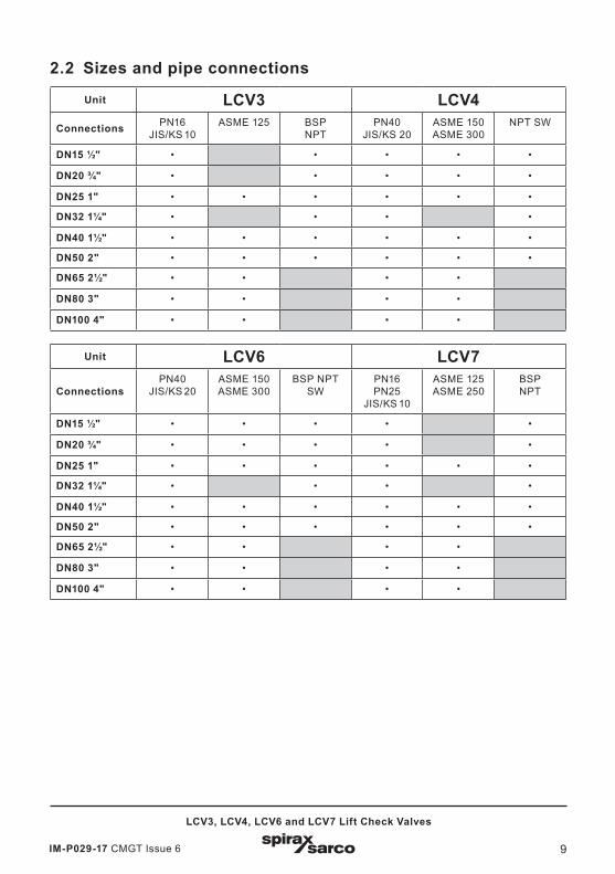
2.2 Sizes and pipe connections
Unit LCV3 LCV4Connections PN16
JIS/KS 10ASME 125 BSP
NPTPN40
JIS/KS 20ASME 150 ASME 300
NPT SW
DN15 ½" • • • • •
DN20 ¾" • • • • •
DN25 1" • • • • • •
DN32 1¼" • • • •
DN40 1½" • • • • • •
DN50 2" • • • • • •
DN65 2½" • • • •
DN80 3" • • • •
DN100 4" • • • •
Unit LCV6 LCV7
Connections PN40
JIS/KS 20ASME 150 ASME 300
BSP NPT SW
PN16PN25
JIS/KS 10
ASME 125ASME 250
BSPNPT
DN15 ½" • • • • •
DN20 ¾" • • • • •
DN25 1" • • • • • •
DN32 1¼" • • • •
DN40 1½" • • • • • •
DN50 2" • • • • • •
DN65 2½" • • • •
DN80 3" • • • •
DN100 4" • • • •

IM-P029-17 CMGT Issue 610
LCV3, LCV4, LCV6 and LCV7 Lift Check Valves
Tem
pera
ture
°C
��
��
���
���
������
� � � � �� �� ����
� ��� ��� ��� ��� ����� �� ��
���
���
���
���
����
��������������
���
� � � � � �� �� �� ��
� �� �� �� ��� ��� ��� ��� ��� ���
���
������
���
���
2.3 Pressure/temperature limits - LCV3
Tem
pera
ture
°C
Pressure bar g
Steam saturation curve
The product must not be used in this region.
A - B Screwed BSP and flanged EN 1092 PN16.
C - D Screwed NPT, socket weld and flanged ASME 125.
A
B
C
D
Pressure bar g
F
E
Body design conditions JIS/KS 10
PMA Maximum allowable pressure 13.7 bar g @ 120 °C (199 psi g @ 248 °F)
TMA Maximum allowable temperature 220 °C @ 9.8 bar g (428 °F @ 142 psi g)
Minimum allowable temperature 0 °C (32 °F)
PMO Maximum operating pressure for saturated steam service 11.2 bar g (162 psi g)
TMO Maximum operating temperature 220 °C @ 9.8 bar g (428 °F @ 142 psi g)
Minimum operating temperatureNote: For lower operating temperatures consult Spirax Sarco. 0 °C (32 °F)
Designed for a maximum cold hydraulic test pressure of: 20 bar g (290 psi g)
Flanged JIS/KS 10
Pressure psi g
Temperature °F
Pressure psi g
Temperature °F
Steam saturation curve
The product must not be used in this region.
E - F Flanged JIS/KS 10.

IM-P029-17 CMGT Issue 6 11
LCV3, LCV4, LCV6 and LCV7 Lift Check Valves
Screwed and Flanged EN 1092 PN16Body design conditions PN16
PMA Maximum allowable pressure 16 bar g @ 120 °C (232 psi g @ 248 °F)
TMA Maximum allowable temperature 300 °C @ 9.6 bar g (572 °F @ 139 psi g)
Minimum allowable temperature -10 °C (14 °F)
PMO Maximum operating pressure for saturated steam service 13 bar g
TMO Maximum operating temperature 300 °C @ 9.6 bar g (572 °F @ 139 psi g)
Minimum operating temperatureNote: For lower operating temperatures consult Spirax Sarco. -10 °C (14 °F)
Designed for a maximum cold hydraulic test pressure of: 24 bar g (348 psi g)
Flanged ASME 125Body design conditions ASME 125
PMA Maximum allowable pressure 13.8 bar g @ 65 °C (200 psi g @ 149 °F)
TMA Maximum allowable temperature 232 °C @ 8.6 bar g (449 °F @ 125 psi g)
Minimum allowable temperature -10 °C (14 °F)
PMO Maximum operating pressure for saturated steam service 10 bar g (145 psi g)
TMO Maximum operating temperature 232 °C @ 8.6 bar g (449 °F @ 125 psi g)
Minimum operating temperatureNote: For lower operating temperatures consult Spirax Sarco. -10 °C (14 °F)
Designed for a maximum cold hydraulic test pressure of 20.5 bar g (297 psi g)

IM-P029-17 CMGT Issue 612
LCV3, LCV4, LCV6 and LCV7 Lift Check Valves
Tem
pera
ture
°C
��
�����������������
� �� �� �� �� �� ��
� ��� ��� ��� ��� ���
���������
���
���
����
�
���
���
���
���
�� �� �� �� ����
� ��� ��� ��� ��� ��� ��� ���
���������������������
2.4 Pressure/temperature limits - LCV4 Te
mpe
ratu
re °
C
Pressure bar g
A
BCD
Pressure bar g
F
E
Flanged JIS/KS 20
Pressure psi g
Temperature °F
Pressure psi g
Temperature °F
Body design conditions JIS/KS 20
PMA Maximum allowable pressure 34 bar g @ 120 °C (493 psi g @ 248 °F)
TMA Maximum allowable temperature 300 °C @ 32 bar g (572 °F @ 464 psi g)
Minimum allowable temperature 0 °C (32 °F)
PMO Maximum operating pressure for saturated steam service 30 bar g (435 psi g)
TMO Maximum operating temperature 300 °C @ 32 bar g (572 °F @ 464 psi g)
Minimum operating temperatureNote: For lower operating temperatures consult Spirax Sarco. 0 °C (32 °F)
Designed for a maximum cold hydraulic test pressure of: 51 bar g (739 psi g)
Steam saturation curve
Steam saturation curve
The product must not be used in this region.
A - B Screwed NPT, socket weld and flanged ASME 300.
A - C Flanged EN 1092 PN40.
A - D Flanged ASME 150.
The product must not be used in this region.
E - F Flanged JIS/KS 20.
IM-P029-17 CMGT Issue 6 13
LCV3, LCV4, LCV6 and LCV7 Lift Check Valves
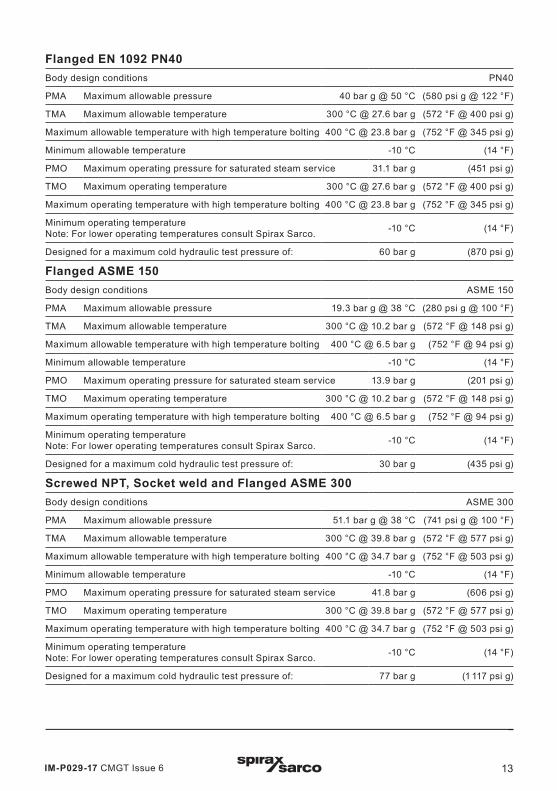
Flanged EN 1092 PN40Body design conditions PN40
PMA Maximum allowable pressure 40 bar g @ 50 °C (580 psi g @ 122 °F)
TMA Maximum allowable temperature 300 °C @ 27.6 bar g (572 °F @ 400 psi g)
Maximum allowable temperature with high temperature bolting 400 °C @ 23.8 bar g (752 °F @ 345 psi g)
Minimum allowable temperature -10 °C (14 °F)
PMO Maximum operating pressure for saturated steam service 31.1 bar g (451 psi g)
TMO Maximum operating temperature 300 °C @ 27.6 bar g (572 °F @ 400 psi g)
Maximum operating temperature with high temperature bolting 400 °C @ 23.8 bar g (752 °F @ 345 psi g)
Minimum operating temperatureNote: For lower operating temperatures consult Spirax Sarco. -10 °C (14 °F)
Designed for a maximum cold hydraulic test pressure of: 60 bar g (870 psi g)
Flanged ASME 150Body design conditions ASME 150
PMA Maximum allowable pressure 19.3 bar g @ 38 °C (280 psi g @ 100 °F)
TMA Maximum allowable temperature 300 °C @ 10.2 bar g (572 °F @ 148 psi g)
Maximum allowable temperature with high temperature bolting 400 °C @ 6.5 bar g (752 °F @ 94 psi g)
Minimum allowable temperature -10 °C (14 °F)
PMO Maximum operating pressure for saturated steam service 13.9 bar g (201 psi g)
TMO Maximum operating temperature 300 °C @ 10.2 bar g (572 °F @ 148 psi g)
Maximum operating temperature with high temperature bolting 400 °C @ 6.5 bar g (752 °F @ 94 psi g)
Minimum operating temperatureNote: For lower operating temperatures consult Spirax Sarco. -10 °C (14 °F)
Designed for a maximum cold hydraulic test pressure of: 30 bar g (435 psi g)
Screwed NPT, Socket weld and Flanged ASME 300Body design conditions ASME 300
PMA Maximum allowable pressure 51.1 bar g @ 38 °C (741 psi g @ 100 °F)
TMA Maximum allowable temperature 300 °C @ 39.8 bar g (572 °F @ 577 psi g)
Maximum allowable temperature with high temperature bolting 400 °C @ 34.7 bar g (752 °F @ 503 psi g)
Minimum allowable temperature -10 °C (14 °F)
PMO Maximum operating pressure for saturated steam service 41.8 bar g (606 psi g)
TMO Maximum operating temperature 300 °C @ 39.8 bar g (572 °F @ 577 psi g)
Maximum operating temperature with high temperature bolting 400 °C @ 34.7 bar g (752 °F @ 503 psi g)
Minimum operating temperatureNote: For lower operating temperatures consult Spirax Sarco. -10 °C (14 °F)
Designed for a maximum cold hydraulic test pressure of: 77 bar g (1 117 psi g)

IM-P029-17 CMGT Issue 614
LCV3, LCV4, LCV6 and LCV7 Lift Check Valves
Tem
pera
ture
°C
��
�����������������
� �� �� �� �� �� ��
� ��� ��� ��� ��� ���
���������
���
���
����������������
�
���
���
���
���� ��� ��� ��� ��� ��� ��� ���
���������������������
2.5 Pressure/temperature limits - LCV6
Tem
pera
ture
°C
Pressure bar g
A
BCD
Pressure bar g
F
E
Flanged JIS/KS 20
Pressure psi g
Temperature °F
Pressure psi g
Temperature °F
Body design conditions JIS/KS 20
PMA Maximum allowable pressure 34 bar g @ 120 °C (493 psi g @ 248 °F)
TMA Maximum allowable temperature 300 °C @ 32 bar g (572 °F @ 464 psi g)
Minimum allowable temperature 0 °C (32 °F)
PMO Maximum operating pressure for saturated steam service 23.5 bar g (431 psi g)
TMO Maximum operating temperature 300 °C @ 32 bar g (572 °F @ 464 psi g)
Minimum operating temperatureNote: For lower operating temperatures consult Spirax Sarco. 0 °C (32 °F)
Designed for a maximum cold hydraulic test pressure of: 51 bar g (739 psi g)
The product must not be used in this region.
A - B Screwed NPT, socket weld and flanged ASME 300.
A - C Flanged EN 1092 PN40.
A - D Flanged ASME 150.
The product must not be used in this region.
E - F Flanged JIS/KS 20.
Steam saturation curve
Steam saturation curve

IM-P029-17 CMGT Issue 6 15
LCV3, LCV4, LCV6 and LCV7 Lift Check Valves
Screwed BSP and Flanged EN 1092 PN40Body design conditions PN40
PMA Maximum allowable pressure 40 bar g @ 50 °C (580 psi g @ 122 °F)
TMA Maximum allowable temperature 400 °C @ 27.4 bar g (752 °F @ 397 psi g)
Minimum allowable temperature -10 °C (14 °F)
PMO Maximum operating pressure for saturated steam service 32.3 bar g (468 psi g)
TMO Maximum operating temperature 400 °C @ 27.4 bar g (752 °F @ 397 psi g)
Minimum operating temperatureNote: For lower operating temperatures consult Spirax Sarco. -10 °C (14 °F)
Designed for a maximum cold hydraulic test pressure of: 60 bar g (870 psi g)
Screwed NPT, Socket weld and Flanged ASME 300Body design conditions ASME 300
PMA Maximum allowable pressure 49.6 bar g @ 38 °C (719 psi g @ 100 °F)
TMA Maximum allowable temperature 400 °C @ 29.4 bar g (752 °F @ 426 psi g)
Minimum allowable temperature -10 °C (14 °F)
PMO Maximum operating pressure for saturated steam service 34 bar g (493 psi g)
TMO Maximum operating temperature 400 °C @ 29.4 bar g (752 °F @ 426 psi g)
Minimum operating temperatureNote: For lower operating temperatures consult Spirax Sarco. -10 °C (14 °F)
Designed for a maximum cold hydraulic test pressure of: 76 bar g (1 102 psi g)
Flanged ASME 150Body design conditions ASME 150
PMA Maximum allowable pressure 19 bar g @ 38 °C (275 psi g @ 100 °F)
TMA Maximum allowable temperature 400 °C @ 6.5 bar g (752 °F @ 94 psi g)
Minimum allowable temperature -10 °C (14 °F)
PMO Maximum operating pressure for saturated steam service 13.8 bar g (200 psi g)
TMO Maximum operating temperature 400 °C @ 6.5 bar g (752 °F @ 94 psi g)
Minimum operating temperatureNote: For lower operating temperatures consult Spirax Sarco. -10 °C (14 °F)
Designed for a maximum cold hydraulic test pressure of: 30 bar g (435 psi g)

IM-P029-17 CMGT Issue 616
LCV3, LCV4, LCV6 and LCV7 Lift Check Valves
Tem
pera
ture
°C
��
�����������������
� � � � �� �� ����
� ��� ��� ��� ��� ����� �� ��
���������
���
���
���
������
���
���
� ��� ��� ��� ��� ���
2.6 Pressure/temperature limits - LCV7
Tem
pera
ture
°C
Pressure bar g
A
D
H B G
Pressure bar g
F
E
C
Flanged JIS/KS 10
Pressure psi g
Temperature °F
Pressure psi g
Temperature °F
Body design conditions JIS/KS 10
PMA Maximum allowable pressure 13.7 bar g @ 120 °C (199 psi g @ 248 °F)
TMA Maximum allowable temperature 300 °C @ 9.8 bar g (572 °F @ 142 psi g)
Minimum allowable temperature 0 °C (32 °F)
PMO Maximum operating pressure for saturated steam service 12.3 bar g (178 psi g)
TMO Maximum operating temperature 300 °C @ 9.8 bar g (572 °F @ 142 psi g)
Minimum operating temperatureNote: For lower operating temperatures consult Spirax Sarco. 0 °C (32 °F)
Designed for a maximum cold hydraulic test pressure of: 20 bar g (290 psi g)
The product must not be used in this region.
A - B Screwed BSP and flanged EN 1092 PN25.
A - C Screwed NPT and flanged EN 1092 PN16.
D - G Flanged ASME 250.
D - H Flanged ASME 125.
The product must not be used in this region.
E - F Flanged JIS/KS 10
Steam saturation curve
Steam saturation curve

IM-P029-17 CMGT Issue 6 17
LCV3, LCV4, LCV6 and LCV7 Lift Check Valves
Flanged EN 1092 PN16Body design conditions PN16
PMA Maximum allowable pressure 16 bar g @ 120 °C (232 psi g @ 248 °F)
TMA Maximum allowable temperature 300 °C @ 12.8 bar g (572 °F @ 185 psi g)
Minimum allowable temperature -10 °C (14 °F)
PMO Maximum operating pressure for saturated steam service 14.7 bar g (213 psi g)
TMO Maximum operating temperature 300 °C @ 12.8 bar g (572 °F @ 185 psi g)
Minimum operating temperatureNote: For lower operating temperatures consult Spirax Sarco. -10 °C (14 °F)
Designed for a maximum cold hydraulic test pressure of: 24 bar g (348 psi g)
Screwed BSP and Flanged EN 1092 PN25Body design conditions PN25
PMA Maximum allowable pressure 25 bar g @ 120 °C (462 psi g @ 248 °F)
TMA Maximum allowable temperature 300 °C @ 20 bar g (572 °F @ 290 psi g)
Minimum allowable temperature -10 °C (14 °F)
PMO Maximum operating pressure for saturated steam service 22.5 bar g (326 psi g)
TMO Maximum operating temperature 300 °C @ 20 bar g (572 °F @ 290 psi g)
Minimum operating temperatureNote: For lower operating temperatures consult Spirax Sarco. -10 °C (14 °F)
Designed for a maximum cold hydraulic test pressure of: 38 bar g (551 psi g)
Flanged ASME 125Body design conditions ASME 125
PMA Maximum allowable pressure 13.8 bar g @ 65 °C (200 psi g @ 149 °F)
TMA Maximum allowable temperature 232 °C @ 8.6 bar g (449 °F @ 125 psi g)
Minimum allowable temperature -10 °C (14 °F)
PMO Maximum operating pressure for saturated steam service 10 bar g (145 psi g)
TMO Maximum operating temperature 232 °C @ 8.6 bar g (449 °F @ 125 psi g)
Minimum operating temperatureNote: For lower operating temperatures consult Spirax Sarco. -10 °C (14 °F)
Designed for a maximum cold hydraulic test pressure of: 20.5 bar g (297 psi g)
Screwed NPT and Flanged ASME 250Body design conditions ASME 250
PMA Maximum allowable pressure 34.5 bar g @ 65 °C (500 psi g @ 149 °F)
TMA Maximum allowable temperature 232 °C @ 17.2 bar g (449 °F @ 249 psi g)
Minimum allowable temperature -10 °C (14 °F)
PMO Maximum operating pressure for saturated steam service 19.4 bar g (281 psi g)
TMO Maximum operating temperature 232 °C @ 17.2 bar g (449 °F @ 249 psi g)
Minimum operating temperatureNote: For lower operating temperatures consult Spirax Sarco. -10 °C (14 °F)
Designed for a maximum cold hydraulic test pressure of: 52 bar g (754 psi g)

IM-P029-17 CMGT Issue 618
LCV3, LCV4, LCV6 and LCV7 Lift Check Valves
2.7 Dimensions (approximate) in mm Please note: Flanged ASME versions are (approximate) in inches
Dimension A
Connection
Screwed
BSP
Socket weld
Flanged
PN40PN16PN25
JIS 10/KS 10JIS 20/KS 20
Screwed
NPT
Flanged
ASME 125
Flanged
ASME 150
Flanged
ASME 250ASME 300
LCV3 LCV7
DN15 ½" 130 130 6½" 7¼" 7¼" 7½"
DN20 ¾" 155 150 6½" 7¼" 7¼" 7½"
DN25 1" 160 160 7¾" 7¼" 7¼" 7¼" 7¾"
DN32 1¼" 185 180 8½"
DN40 1½" 205 200 9¼" 8¾" 8¾" 8¾" 9¼"
DN50 2" 230 230 10½" 10" 10" 10" 10½"
DN65 2½" 290 10½" 10½" 107/8" 11½"
DN80 3" 310 11¾" 11¾" 11¾" 12½"
DN100 4" 350 13¾" 13¾" 137/8" 14½"
A
B
FlangedScrewed and Socket weld
Fig. 2
A
C Withdrawal distance

IM-P029-17 CMGT Issue 6 19
LCV3, LCV4, LCV6 and LCV7 Lift Check Valves
Dimension B
Connection
Screwed
BSP
Socket weld
Flanged
PN40PN16PN25
JIS 10/KS 10JIS 20/KS 20
Screwed
NPT
Flanged
ASME 125
Flanged
ASME 150
Flanged
ASME 250ASME 300
LCV3 LCV7
DN15 ½" 88 88 4" 4" 4" 4" 4"
DN20 ¾" 88 88 4" 4" 4" 4" 4"
DN25 1" 88 88 4" 4" 4" 4" 4"
DN32 1¼" 117 117 53/16"
DN40 1½" 117 117 53/16" 53/16" 53/16" 53/16" 53/16"
DN50 2" 117 117 53/16" 53/16" 53/16" 53/16" 53/16"
DN65 2½" 166 77/8" 77/8" 77/8" 77/8"
DN80 3" 166 77/8" 77/8" 77/8" 77/8"
DN100 4" 180 8½" 8½" 8½" 8½"
Dimension C
Connection All sizes
DN15 ½" 143
DN20 ¾" 143
DN25 1" 143
DN32 1¼" 182
DN40 1½" 182
DN50 2" 182
DN65 2½" 260
DN80 3" 260
DN100 4" 300

IM-P029-17 CMGT Issue 620
LCV3, LCV4, LCV6 and LCV7 Lift Check Valves
2.9 Weights (approximate) in kg
Unit
LCV3 LCV4 LCV6 LCV7
Flanged Screwed FlangedScrewedSocket weld
FlangedScrewedSocket weld
Flanged Screwed
DN15 ½" 4.30 3.10 5.05 3.65 5.19 3.79 4.64 3.24
DN20 ¾" 5.50 4.10 6.43 5.33 6.60 5.50 5.89 4.29
DN25 1" 5.82 4.10 6.58 4.18 6.77 4.37 6.04 3.74
DN32 1¼" 10.23 7.20 12.89 9.59 13.37 10.07 11.99 8.69
DN40 1½" 11.43 8.00 14.35 9.55 14.77 9.97 13.18 9.28
DN50 2" 14.96 10.50 16.86 12.06 17.51 12.71 15.65 10.65
DN65 2½" 27.04 32.25 33.13 29.53
DN80 3" 29.47 36.02 37.00 33.00
DN100 4" 48.93 52.06 53.47 48.82
2.8 Product name-plate
Fig. 3
Description
PMA
T max
Code number
TMO
T min

IM-P029-17 CMGT Issue 6 21
LCV3, LCV4, LCV6 and LCV7 Lift Check Valves
Note: Before actioning any installation observe the 'Safety information' in Section 1.
Referring to the Installation and Maintenance Instructions, name-plate and Technical Information Sheet, check that the product is suitable for the intended installation:
3.1 Check materials, pressure and temperature and their maximum values. If the maximum operating limit of the product is lower than that of the system in which it is being fitted, ensure that a safety device is included in the system to prevent overpressurisation.
3.2 Determine the correct installation situation and the direction of fluid flow.
3.3 Remove protective covers from all connections and the protective film from all name-plates, where appropriate, before installation on steam or other high temperature applications.
3.4 The LCV is designed for installation in horizontal and vertical pipework (see Figure 4).
3.5 Always fit a non-return (check) valve downstream of any steam traps which discharge into condensate return lines where backpressure is experienced. This is most commonly caused by a rising condensate line. The check valve will prevent the steam space flooding when the inlet pressure is reduced or the steam is shut off.
3.6 When the LCV is installed after a blast action steam trap (thermodynamic and inverted bucket), it should be positioned at least 1 m (3 ft) downstream of the outlet.
3.7 Isolation valves must be installed to allow for safe maintenance and check valve replacement.
3.8 Open isolation valves slowly until normal operating conditions are achieved.
3.9 Check for leaks and correct operation.
3.10 Ensure adequate space is left to remove the cover from the body for maintenance - See Section 2.4, minimum withdrawal distance 'C'.
3.11 Welding into the pipeline - LCV4 and LCV6 socket weld connections. For specific weld procedures consult the relevant National and International welding standards.
Note: If a trap is to discharge to atmosphere ensure it is to a safe place as the discharging fluid may be at a temperature of 100 °C (212 °F).
Fig. 4
Cover
Cover
Cover
3. Installation

IM-P029-17 CMGT Issue 622
LCV3, LCV4, LCV6 and LCV7 Lift Check Valves
After installation or maintenance ensure that the system is fully functional. Carry out tests on any alarms or protective devices.
LCV check valves are opened by the pressure of the fluid and closed by the spring as soon as the flow ceases and before the reverse flow occurs.
Fig. 5
Open
Closed
4. Commissioning
5. Operation

IM-P029-17 CMGT Issue 6 23
LCV3, LCV4, LCV6 and LCV7 Lift Check Valves
6.1 Spare partsThe spare parts available are shown in solid outline. Parts drawn in broken line are not supplied as spares.
Available sparesLCV Gaskets kit (Cover gasket and seat gasket) Spare 1
LCV Internals kit (Cover gasket, seat gasket, spring, disc and seat)
Spare 2
How to order sparesAlways order spares by using the description given in the column headed 'Available spares' and state the size and type of trap. Always order spares by using the description of the LCV and Spare 1 or Spare 2.Example: 1 off LCV Internals kit – Spare 2, for a Spirax Sarco DN15 LCV4 lift check valve having flanged EN 1092 PN40 connections.
1
1
2
Fig. 6
6. Spare parts and Maintenance

IM-P029-17 CMGT Issue 624
LCV3, LCV4, LCV6 and LCV7 Lift Check Valves
8
1
3a
5
9
7
6
3b
4
2
Fig. 7
6.2 MaintenanceNote: Before actioning any maintenance p r o g r a m m e o b s e r v e t h e ' S a f e t y information' in Section 1.
6.2.1 How to renew the cover gasket (3a) and seat gasket (3b):- Isolate the LCV and allow the pressure
and temperature to reduce to ambient conditions.
- After isolation, unscrew the bolts (8) and remove the cover (1), old gasket (3a) and cage (9).
- Remove the spring (7) and the disc (6).
- Remove the seat (4) and the seat gasket (3b).
- Carefully clean the recess.
- Refit new seat gasket (3b) and cover gasket (3a).
- Replace the internals - seat (4) and cage (9) after refitting the disc (6) and spring (7).
- Replace the cover (1) and the bolts (8) (for the LCV6 version you must lubricate the screws when refitting the bolt) and tighten to the recommended torque (see Table 1).
- After maintenance has been completed, isolation valves should be opened slowly to allow pressure and temperature to build up in a controlled manner.
- Check for leaks.

IM-P029-17 CMGT Issue 6 25
LCV3, LCV4, LCV6 and LCV7 Lift Check Valves
6.2.2 How to renew the internal parts - Disc (6), Spring (7) and Seat (4):- Isolate the LCV and allow the pressure
and temperature to reduce to ambient conditions.
- After isolation, unscrew the bolts (8) and remove the cover (1), old gasket (3a) and cage (9).
- Remove the spring (7) and the disc (6).
- Remove the seat (4) and the seat gasket (3b).
- Carefully clean the recess.
- Refit new seat gasket (3b) and cover gasket (3a).
- Refit new internals - Seat (4), Disc (6) and Spring (7).
- Replace the cage (9).
- Replace the cover (1) and the bolts (8) (for the LCV6 version you must lubricate the screws when refitting the bolt) and tighten to the recommended torque (see Table 1).
- After maintenance has been completed, isolation valves should be opened slowly to allow pressure and temperature to build up in a controlled manner.
- Check for leaks.
8
1
3a
5
9
7
6
3b
4
2
Fig. 8

IM-P029-17 CMGT Issue 626
LCV3, LCV4, LCV6 and LCV7 Lift Check Valves
Item Size TorqueN m
(Ibf ft)EN ASME EN ASME
8
DN15 to DN25(½" to 1")
LCV3 17 A/F7/8" A/F
LCV3 M10½" - 13 UNC 40 - 50
(30 - 37)Others 19 A/F Others M12
DN32 to DN50(1¼" to 2")
LCV3 19 A/F11/16" A/F
LCV3 M125/8" - 11 UNC 80 - 90
(59 - 66)Others 24 A/F Others M16
DN65 to DN80(2½" to 3") 24 A/F 1¼" A/F M16 ¾" - 9 UNC 90 - 100
(66 - 74)
DN100(4") 24 A/F 11/16" A/F M16 5/8" - 11 UNC 70 - 80
(52 - 59)
Table 1 Recommended tightening torque

IM-P029-17 CMGT Issue 6 27
LCV3, LCV4, LCV6 and LCV7 Lift Check Valves

IM-P029-17 CMGT Issue 628
LCV3, LCV4, LCV6 and LCV7 Lift Check Valves