ld9000 pole display user manual - home -...
TRANSCRIPT
i
USB Interface Customer Displays 2 by 20 character display
USER MANUAL
Rev 1.0
Model: LD1000 Series

ii
NOTICE
The manufacturer of the POS pole display makes no representations or warranties, either expressed or implied, by or with respect to anything in this manual, and shall not be liable for any implied warranties of fitness for a particular purpose or for any indirect, special or consequential damages. Information in this document is subject to change without notice and does not represent a commitment on the part of the manufacturer.
FCC NOTICE
This equipment generates, uses, and can radiate radio frequency energy and if not installed and used in accordance with this manual, may cause interference to radio communications. It has been tested and found to comply with the limits for a Class A digital device pursuant to Subpart J of Part 15 of FCC Rules, which are designed to provide reasonable protection against interference when operated in a commercial environment. Operation of this equipment in a residential area is likely to cause interference in which case the user at his own expense will be required to take whatever measures may be required to correct the interference.
LOGIC CONTROLS, INC.
355 Denton Avenue New Hyde Park, NY 11040
TEL: (516) 248-0400 FAX: (516) 248-0443
Email: [email protected] http://www.logiccontrols.com
iii
TABLE OF CONTENTS
FEATURES ............................................................................... 1
CARTON CONTENTS .............................................................. 2
HARDWARE INSTALLATION .................................................. 3
DRIVER INSTALLATION ......................................................... 3
SOFTWARE COMMAND SET DOWNLOAD .......................... 9
FUNCTIONAL TEST ............................................................... 11
SET COMMAND LD-1000 DESCRIPTION ........................... 13
LOGIC CONTROLS COMMAND SET (LCI) .......................................... 13 NORITAKI EMULATION COMMAND SET .......................................... 17 SUPPORTED AEDEX EMULATION COMMAND SET ........................ 19 EMAX EMULATION COMMAND SET .................................................. 20 FIRICH EMULATION COMMAND SET ................................................ 21 PTC 7220 EMULATION COMMAND SET ............................................. 22 PD 3400 EMULATION COMMAND SET................................................ 23 IEE EMULATION COMMAND SET ....................................................... 24 UTCE 1100E EMULATION COMMAND SET ........................................ 25 UTC 1100S EMULATION COMMAND SET .......................................... 26 EPSON 110-D202 EMULATION COMMAND SET ................................ 27
CHARACTER CODE TABLES ............................................... 28
GENERAL SPECIFICATIONS ............................................... 34

1
FEATURES
The LD1000 family of USB port powered universal pole displays has been pre-assembled to make the installation as simple as possible. The model identification chart will assist you in selecting the model best suited to the application needs.
Two line display with twenty 9mm high characters each line
Bright green fluorescent display
Downloadable command sets
OPOS/JPOS compatible
Available in dark gray
Standard USB interface
USB port powered with cable

2
CARTON CONTENTS
1. Pole display pre-assembled with cable USB connector.
2. Metal base plate with mounting hardware.
3. Quick Installation Guide.

3
HARDWARE INSTALLATION
1. Mount the pole display to the metal base plate using the mounting hardware provided.
2. The pole display can be used in a freestanding mode or attached to the
counter using the remaining mounting hardware.
3. Install USB driver first as described in “DRIVER INSTALLTION” section.
4. Plug the USB cable from the pole display into the computer‟s USB port.
DRIVER INSTALLATION a) For Windows XP, Vista and Seven:
The USB drivers are available on our web site at www.logiccontrols.com. Please download and unzip the driver files before installation. There are two types of driver interface available. If the POS software is only able to access standard COM ports for the pole displays, use the Virtual COM port interface. After the driver is installed, Windows Device Manager will assign a COM port name to the device so the POS software can communicate with the USB display as a standard serial RS232 device. Note that the operating system will assign the display a different COM port number if the display is plugged into a different USB port. Another driver interface uses a specific device name (\\.\LCLD1\) to access the pole display directly. In this case, if your POS application uses this device name instead of the COM name to control the pole display, you don‟t have to worry about different COM names for different USB ports. These are the steps to install the driver:
1. DO NOT plug the device in USB port
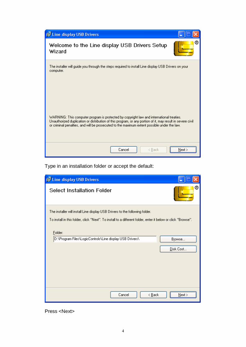
2. Run “setup.msi” program found in the driver package to pre-install line display driver software package.
4
Type in an installation folder or accept the default:
Press <Next>

5
Pres <Close> to end the installation process.

6
3. Plug the device in USB port and wait for the hardware wizard message box to
display (For Windows XP only):
4. (For Windows XP only) Check "No, not this time" radio button and then click
<Next> button.
5. (For Windows XP only) Click <Next> to continue installation automatically. When finished, click <Finish> to end installation (this can take some seconds):

7
6. Invoke Device Manager to check COM port number or the device driver's name. The device, when connected, will be shown under "Ports (COM & LPT)" :
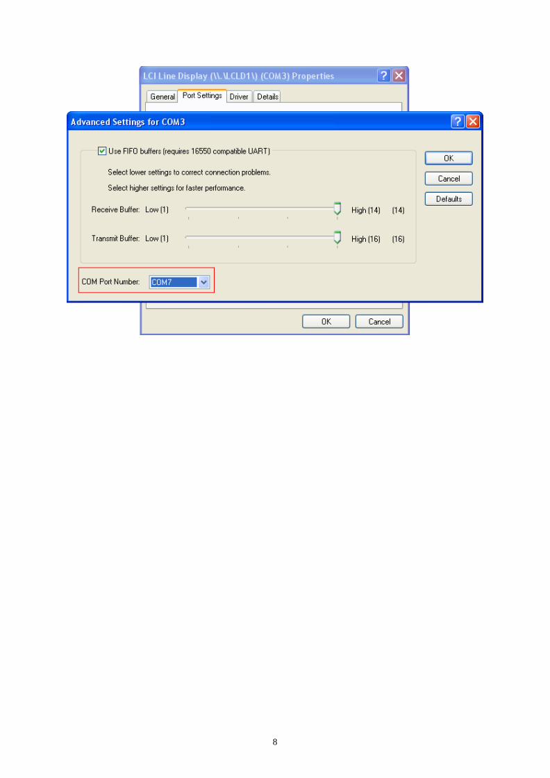
7. To change the assigned COM port number, double click "LCI Line Display (\\.\LCLD1\) (COMx)" to display the Properties dialog box and select <Port Settings> tab. Then click <Advanced...> button
8. Click on COM port number box to select from the list of unused port number and click <OK> to accept new settings (example COM7):
8

9
SOFTWARE COMMAND SET DOWNLOAD Logic Controls LD1000 pole displays are controlled by command codes and data sent from the computer. The display is able to emulate different popular command sets to meet requirements of different POS software. Please download the required command set to the display according to the POS software needs using the download utility software. This utility software (LD1000_Download.exe) and the command set hex files are available in our web site at www.logiccontrols.com. Please download and uncompress the files before installation. Check SET COMMAND LD-1000 DESCRIPTION for further information about the command sets supported by the device.
1. If the LD-1000 is connected to the PC, disconnect in and then connect it again. Do not send any command to the LD-1000 before transferring the hex file.
2. Launch the utility software. Select a port name or the device name “\\.\LCLD1\”. Click <OK> button:
3. Select the desired command set and click <Start Download> (example below shows the uploading of the Logic Controls command set):
4. The display of LD-1000 should show the message below:
LOGIC CONTROLS
DOWNLOADING CODE

10
5. Wait for the final message:
The display of LD-1000 should show:
xxxx = Name of command set.
Example: <LCI> for Logic Controls Vy.yy = Firmware version.
6. When display of LD-1000 shows the message below you have to go to step 2 – 5, and download the command set firmware again
LD1000
xxxxx Vy.yy
FIRMWARE IS BAD!
NEED DOWNLOADING

11
FUNCTIONAL TEST
The following test sequence will verify that your pole display is working properly. Before you start this procedure, you must install the pole display correctly as outlined under the INSTALLATION section. The functional test described below is for the LCI command set. Verify that the display is loaded with the LCI command set before testing. The functional test should be done under MSDOS COMMAND prompt in Windows XP, Vista and Seven. NOTE: The actual key entries in the text below are enclosed within quotation marks
(“ ”). Do not type the quotation marks as part of your entries.
Close all opened application programs that use the same COM port before going into COMMAND prompt. Enter the following command lines to open the COM port and test with the pole display: Virtual COM port driver interface
1. Check the assigned COM port number (x) under Device Manager. 2. Open Command Prompt Window.
Type “MODE COMx 96,N,8,1” and press the ENTER key. Type “TYPE CON > COMx” and press the ENTER key. And then you can type command codes to test the display. Use <Ctrl + C> to quit after finishing test.
Device name driver interface
Open Command Prompt Window. Type “TYPE CON > \\.\LCLD1\” and press the ENTER key. And then you can type command codes to test the display. Use <Ctrl + C> to quit after finishing test.
Examples:
1. LCI command set: Type “ABCDEFG”, and the display will show “ABCDEFG” on the first line.
2. Aedex command set:
Type “!#1ABCDEFG” and press the ENTER key. The display will show “ABCDEFG” on the first line.

12
OPOS DRIVER INSTALLATION
If the POS software uses OPOS (OLE-POS) software interface for controlling the pole display operations, OPOS drivers must be installed. The OPOS driver supplied by Logic Controls will work with the default Logic Controls command set.
1. The Logic Controls OPOS display drivers come in a CD or can be downloaded from our website. Either copy all files in the CD into a hard disk folder or use the CD directly for installation.
2. Click on file <setup.exe> to start installation and follow instructions on the screen to go through installation.
3. After installation, setup the OPOS driver by running PDSetup.exe. Start <PDSetup> under Start Menu -> Programs -> LC OPOS -> Setup. The left part of the dialog window is for setting up the configuration and the right part is for testing commands sent to the OPOS display.
4. Select appropriate port name (for USB with device name drivers, select LD1USB). Next, setup LDN (Logic Device Name). Click Add new LDN and a new form will be displayed. Enter a new LDN, for example, "Line Display" and then click OK.
5. To rename an LDN or delete an LDN, click Rename LDN or Delete LDN.
6. To test the pole display, follow the order of buttons. First click "Open", then "Claim", then "Enable Device". Now the pole display is ready to display messages.
7. Click on "DisplayText", a string is displayed on the pole display. Test other functions to verify operations.
8. Click on "Release" and then "Close". Click on "Exit" to quit the program. The OPOS driver has been setup and ready to run OPOS application software.
9. Set up the POS software to use the same Logical Device Name configured in the OPOS driver and test with the POS software.

13
SET COMMAND LD-1000 DESCRIPTION Commands are transmitted to the pole display as ASCII codes. The command codes listed below are expressed in:
Hexadecimal (base 16) numbers enclosed inside angle brackets < >
Decimal numbers enclosed in parenthesis ( )
ASCII characters enclosed in curly brackets { }. Do not include the brackets as part of the command. „ ^ „ character denotes „Ctrl‟ in the keyboard. Press and hold „Ctrl‟, then press the next key.
LOGIC CONTROLS COMMAND SET (LCI)
1. Vertical Scroll Mode <12> or (18) or {^R}
Default mode. Data written to the second row are transferred to the first row when line feed (value is <0A>) is received, leaving the second row empty. The cursor stays in the second line, but in the same column. Send carriage return (value is <0D>) to position the cursor in the first column (of second line).
2. Normal Display Mode <11> or (17) or {^Q}
When line is full, cursor moves to the next line (left aligned).
3. Brightness Control <04> <n> The brightness level (n) of the display can be adjusted using this command
followed by a data byte: n = <20>, 20% n = <40>, 40% n = <60>, 60% n = <FF>, 100%. Mode default.
4. Back Space <08> or (08) or {^H}
The cursor position moves one position to the left erasing the previous character.
5. Horizontal Tab <09> or (09) or {^I}
The cursor position shifts one position to the right without erasing character at original cursor position.
6. Line Feed <0A> or (10) or {^J} The cursor position moves to the same position in the other row. Under vertical scroll mode, if cursor was in second row, it will not move and display will scroll up.
7. Carriage Return <0D> or (13) or {^M}
The cursor moves to the left most position at the current row.
14
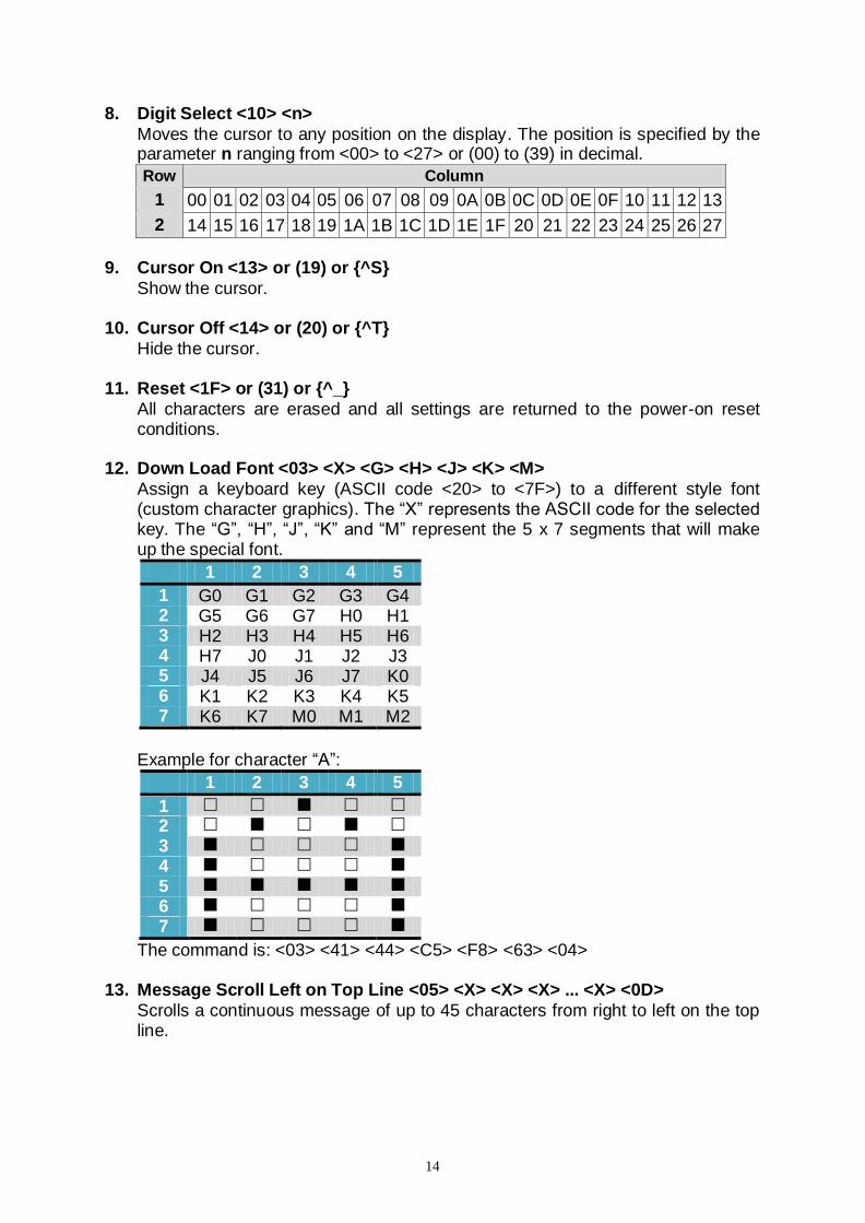
8. Digit Select <10> <n>
Moves the cursor to any position on the display. The position is specified by the parameter n ranging from <00> to <27> or (00) to (39) in decimal.
Row Column
1 00 01 02 03 04 05 06 07 08 09 0A 0B 0C 0D 0E 0F 10 11 12 13
2 14 15 16 17 18 19 1A 1B 1C 1D 1E 1F 20 21 22 23 24 25 26 27
9. Cursor On <13> or (19) or {^S}
Show the cursor. 10. Cursor Off <14> or (20) or {^T}
Hide the cursor.
11. Reset <1F> or (31) or {^_}
All characters are erased and all settings are returned to the power-on reset conditions.
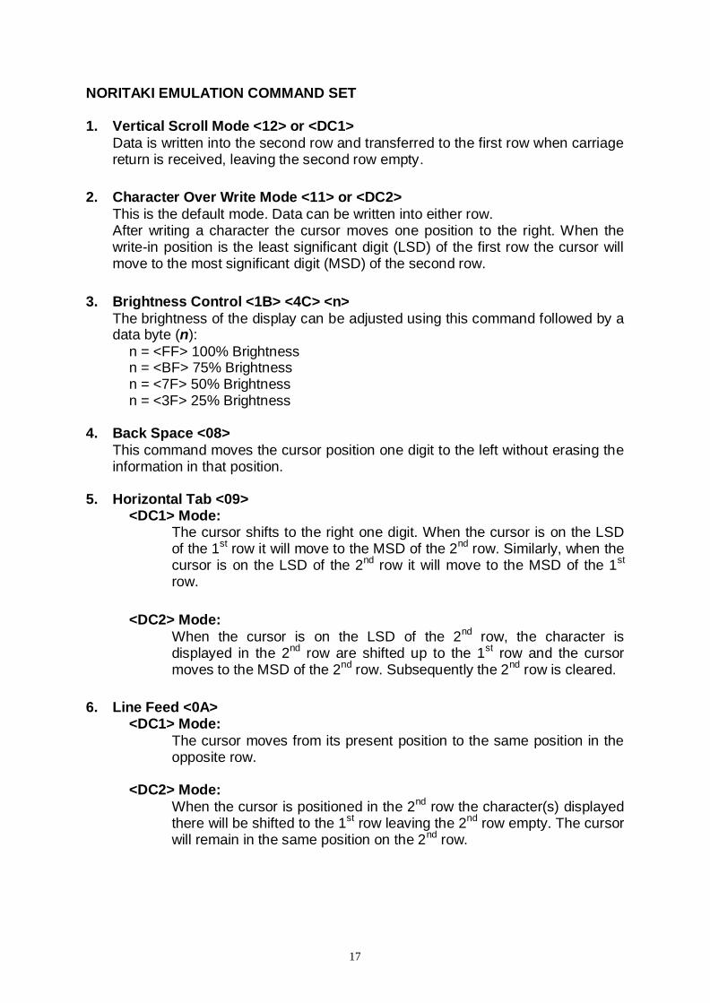
12. Down Load Font <03> <X> <G> <H> <J> <K> <M>
Assign a keyboard key (ASCII code <20> to <7F>) to a different style font (custom character graphics). The “X” represents the ASCII code for the selected key. The “G”, “H”, “J”, “K” and “M” represent the 5 x 7 segments that will make up the special font.
1 2 3 4 5
1 G0 G1 G2 G3 G4 2 G5 G6 G7 H0 H1 3 H2 H3 H4 H5 H6 4 H7 J0 J1 J2 J3 5 J4 J5 J6 J7 K0 6 K1 K2 K3 K4 K5 7 K6 K7 M0 M1 M2
Example for character “A”:
1 2 3 4 5
1
2
3
4
5
6
7
The command is: <03> <41> <44> <C5> <F8> <63> <04>
13. Message Scroll Left on Top Line <05> <X> <X> <X> ... <X> <0D>
Scrolls a continuous message of up to 45 characters from right to left on the top line.

15
14. Message Scroll Left on Bottom Line <1B> <06> <X> <X> <X> ... <X> <0D>
Scrolls a continuous message of up to 45 characters from right to left on the bottom line.
15. Message Scroll Right on Top Line <1B> <07> <X> <X> <X> ... <X> <0D>
Scrolls a continuous message of up to 45 characters from left to right on the top line.
16. Message Scroll Right on Bottom Line <1B> <0B> <X> <X> <X> ... <X><0D>
Scrolls a continuous message of up to 45 characters from left to right on the bottom line.
17. Both Side Display <1B> <0C> or (27) (12) or {^[ ] {^L}
Not applicable to this model of Customer Display.
18. Front Side Display <1B> <0E> or (27)(14) or {^[ ]{^N} Not applicable to this model of Customer Display.
19. Back Side Display <1B> <0F> or (27)(15) or {^[ ]{^O}
Not applicable to this model of Customer Display.
20. Clock Display <1B> <1A> <h><h> <3A> <m><m>
Displays real time clock on bottom line in the 12 hour format <hh:mm>.
21. Smart Message Scroll Left on Top Line <1B> <15> <X> <X> <X> ... <1C> … <1C> … <X> <0D>
Scrolls a multi-part message of up to total of 45 characters from right to left on the top line. Message parts are separated by <1C> and each part must be less than 20 characters.
22. Smart Message Scroll Left on Bottom Line <1B> <16> <X> <X> <X> ... <1C> … <1C> … <X> <0D>
Scrolls a multi-part message of up to total of 45 characters from right to left on the bottom line. Message parts are separated by <1C> and each part must be less than 20 characters.
23. Smart Message Scroll Right on Top Line <1B> <13> <X> <X> <X> ... <1C> … <1C> … <X> <0D>
Scrolls a multi-part message of up to total of 45 characters from left to right on the top line. Message parts are separated by <1C> and each part must be less than 20 characters.
24. Smart Message Scroll Right on Bottom Line <1B> <14> <X> <X> <X> ... <1C> … <1C> … <X> <0D>
Scrolls a multi-part message of up to total of 45 characters from left to right on the bottom line. Message parts are separated by <1C> and each part must be less than 20 characters.
25. Select Font Code <1B> <25> <X>

16
Select font code (0-6) for extended ASCII characters from <80> to <FF>. Refer to the font code tables for list of font selections (see “Character Code Tables” in the end of this manual).
26. Select International Symbols <1B> <26> <X>
Select international symbol set (0-13) for various languages. Refer to the international symbol table for list of language symbol selections (see “Character Code Tables” in the end of this manual).
27. Save Font Code and International Symbols <1B> <27> <n> <m> Save font code <n> (0-6) and international symbol set <m> (0-13). The setting
will be saved and will be loaded at power up. Refer to the font code tables and international symbol table for list of font and language symbol selections (see “Character Code Tables” in the end of this manual).
17
NORITAKI EMULATION COMMAND SET
1. Vertical Scroll Mode <12> or <DC1>
Data is written into the second row and transferred to the first row when carriage return is received, leaving the second row empty.
2. Character Over Write Mode <11> or <DC2>
This is the default mode. Data can be written into either row. After writing a character the cursor moves one position to the right. When the write-in position is the least significant digit (LSD) of the first row the cursor will move to the most significant digit (MSD) of the second row.
3. Brightness Control <1B> <4C> <n>
The brightness of the display can be adjusted using this command followed by a data byte (n):
n = <FF> 100% Brightness n = <BF> 75% Brightness n = <7F> 50% Brightness n = <3F> 25% Brightness
4. Back Space <08>
This command moves the cursor position one digit to the left without erasing the information in that position.
5. Horizontal Tab <09> <DC1> Mode:
The cursor shifts to the right one digit. When the cursor is on the LSD of the 1
st row it will move to the MSD of the 2
nd row. Similarly, when the
cursor is on the LSD of the 2nd
row it will move to the MSD of the 1st
row.
<DC2> Mode:
When the cursor is on the LSD of the 2nd
row, the character is displayed in the 2
nd row are shifted up to the 1
st row and the cursor
moves to the MSD of the 2nd
row. Subsequently the 2nd
row is cleared.
6. Line Feed <0A>
<DC1> Mode:
The cursor moves from its present position to the same position in the opposite row.
<DC2> Mode:
When the cursor is positioned in the 2nd
row the character(s) displayed there will be shifted to the 1
st row leaving the 2
nd row empty. The cursor
will remain in the same position on the 2nd
row.

18
7. Carriage Return <0D>
The cursor moves to the MSD of the row that it is in.
8. Digit Select <1B> <48> <P> Moves the cursor to any position on the display. “P” is the digit position where the cursor is to be moved to. P is represented as a 2 digit hex number.
9. Cursor On <15>
The cursor is on or lighted as an underline. Selected as the default value when power is turned on.
10. Cursor Off <16>
Turns off the cursor. 11. Reset <1B> <49>
All characters are erased and all settings are turned to the power-on reset conditions.
12. Clear <0E>
All displayed characters are cleared. The cursor does not move. 13. Alphanumeric Message Scroll <05> <X> … <0D>
A message of up 45 characters will be continuously scrolled on the first line of the display. The message will continue to scroll until another attention code is received by the display.
14. Back Space <08>
This command moves the cursor position one digit to the left without erasing the information in that position.
15. Down Load Font <1B> <43> <X> <F> <F> <F> <F> <F>
Allows a programmer to assign a keyboard key (00 Hex to FF Hex) a different style font.
- The <1B> <43> represents the command code; - The <X> represents the selected key; - The <F> represent the 5 segments which will make up the special font.

19
SUPPORTED AEDEX EMULATION COMMAND SET
Top Line - Alphanumeric <21> <23> <31> <Data> <0D>
Bottom Line – Alphanumeric <21> <23> <32> <Data> <0D>
Alphanumeric Message Scroll <21> <23> <34> <Data> <0D>
Time Display <21> <23> <35> <h><h> <3A> <m><m> <0D>
One Time Alphanumeric Message Scroll <21> <23> <36> <Data> <0D>
Change Attention Code <21> <23> <38> <H1> <H2>
Send Up to 40 Alphanumeric Characters <21> <23> <39> <Data>> <0D>

20
EMAX EMULATION COMMAND SET
Write to Line 1 <21> <23> <31> <Data> <0D>
Write to Line 2 <21> <23> <32> <Data> <0D>
Set and Display 24 Hour Clock:
Display 24 Hour Clock <21> <23> <35> <0D>
Change the Aedex Command Prefix <21> <23> <38> <Data> <0D>
Write Two Lines <21> <23> <39> <Data> <0D>
Auto Scan Message (Single Pass) <21> <23> <36> <Data> <0D>
Auto Scan Message (Continuous) <21> <23> <34> <Data> <0D>

21
FIRICH EMULATION COMMAND SET
Overwrite Mode <1B> <11> or <1B> <40>
Vertical Scroll Mode <1B> <12>
Horizontal Scroll Mode <1B> <13>
String Display Mode: o Write string to upper line <1B> <51> <41> d1…dn <0D> o Write string to lower line <1B> <51> <42> d1…dn <0D>
String Display Mode:
Write string to the upper line and scroll the message continuously: o <1B> <51> <44> d1…dn <0D>
Move the cursor up one line <1B> <5B> <41>
Move cursor down <1B> <5B> <42> or <0A>
Move cursor right <1B> <5B> <43> or <09>
Move cursor left <1B> <5B> <44> or <08>
Move cursor to home position <1B> <5B> <48> or <0B>
Move cursor to left-most position <1B> <5B> <4C> or <0D>
Move cursor to the right-most position <1B> <5B> <52>
Move cursor to the bottom position <1B> <5B> <4B>
Move cursor to the specified position <1B> <6C> X Y
Initialize display <1B> <40>
Clear display screen and clear string mode <0C>
Clear cursor line and clear string mode <18>
Set cursor ON or OFF <1B> <5F> n
Set or cancel the window range at horizontal scroll mode: o <1B> <57> <00> o <1B> <57> <01> X1 X2 Y
Define user-defined characters <1B><26><01> n m [a (p1.. pa) x (m – n + 1)]
Select International font set <1B> <66> n
Select code set <1B> <63> n
Undefined user-defined character <1B> <3F> n
Select/cancel user-defined character set <1B> <25> n
Store user-defined character in EEPROM <1B> <73> <01>
Restore user-defined character from EEPROM <1B> <64> <01>
Save current display data in EEPROM <1B> <53> n
Display saved data from EEPROM <1B> <44> n m
Adjust brightness <1B> <2A> n
Set output device mode <1B> <3D> n
22
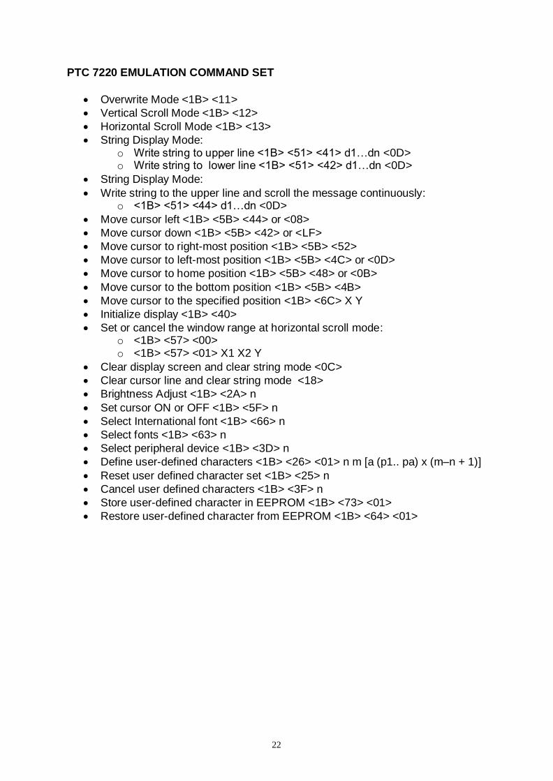
PTC 7220 EMULATION COMMAND SET
Overwrite Mode <1B> <11>
Vertical Scroll Mode <1B> <12>
Horizontal Scroll Mode <1B> <13>
String Display Mode: o Write string to upper line <1B> <51> <41> d1…dn <0D> o Write string to lower line <1B> <51> <42> d1…dn <0D>
String Display Mode:
Write string to the upper line and scroll the message continuously: o <1B> <51> <44> d1…dn <0D>
Move cursor left <1B> <5B> <44> or <08>
Move cursor down <1B> <5B> <42> or <LF>
Move cursor to right-most position <1B> <5B> <52>
Move cursor to left-most position <1B> <5B> <4C> or <0D>
Move cursor to home position <1B> <5B> <48> or <0B>
Move cursor to the bottom position <1B> <5B> <4B>
Move cursor to the specified position <1B> <6C> X Y
Initialize display <1B> <40>
Set or cancel the window range at horizontal scroll mode: o <1B> <57> <00> o <1B> <57> <01> X1 X2 Y
Clear display screen and clear string mode <0C>
Clear cursor line and clear string mode <18>
Brightness Adjust <1B> <2A> n
Set cursor ON or OFF <1B> <5F> n
Select International font <1B> <66> n
Select fonts <1B> <63> n
Select peripheral device <1B> <3D> n
Define user-defined characters <1B> <26> <01> n m [a (p1.. pa) x (m–n + 1)]
Reset user defined character set <1B> <25> n
Cancel user defined characters <1B> <3F> n
Store user-defined character in EEPROM <1B> <73> <01>
Restore user-defined character from EEPROM <1B> <64> <01>
23
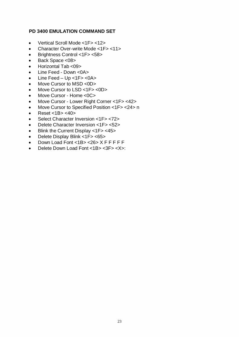
PD 3400 EMULATION COMMAND SET
Vertical Scroll Mode <1F> <12>
Character Over-write Mode <1F> <11>
Brightness Control <1F> <58>
Back Space <08>
Horizontal Tab <09>
Line Feed - Down <0A>
Line Feed – Up <1F> <0A>
Move Cursor to MSD <0D>
Move Cursor to LSD <1F> <0D>
Move Cursor - Home <0C>
Move Cursor - Lower Right Corner <1F> <42>
Move Cursor to Specified Position <1F> <24> n
Reset <1B> <40>
Select Character Inversion <1F> <72>
Delete Character Inversion <1F> <52>
Blink the Current Display <1F> <45>
Delete Display Blink <1F> <65>
Down Load Font <1B> <26> X F F F F F
Delete Down Load Font <1B> <3F> <X>:
24
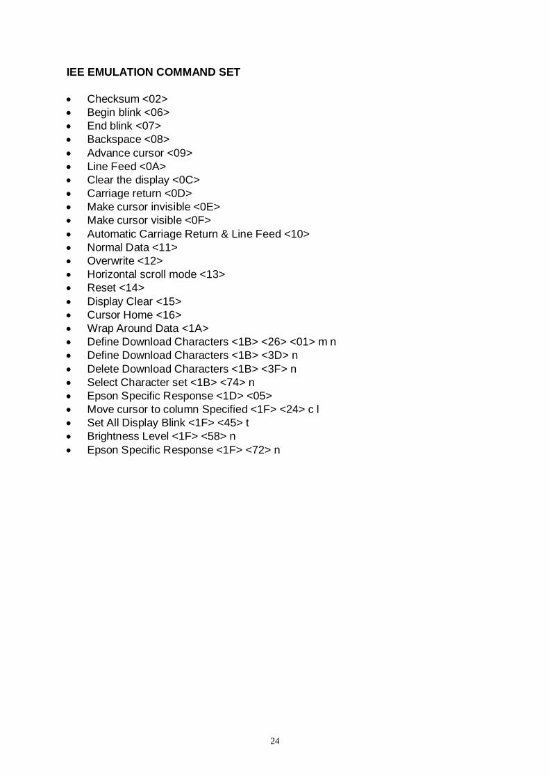
IEE EMULATION COMMAND SET
Checksum <02>
Begin blink <06>
End blink <07>
Backspace <08>
Advance cursor <09>
Line Feed <0A>
Clear the display <0C>
Carriage return <0D>
Make cursor invisible <0E>
Make cursor visible <0F>
Automatic Carriage Return & Line Feed <10>
Normal Data <11>
Overwrite <12>
Horizontal scroll mode <13>
Reset <14>
Display Clear <15>
Cursor Home <16>
Wrap Around Data <1A>
Define Download Characters <1B> <26> <01> m n
Define Download Characters <1B> <3D> n
Delete Download Characters <1B> <3F> n
Select Character set <1B> <74> n
Epson Specific Response <1D> <05>
Move cursor to column Specified <1F> <24> c l
Set All Display Blink <1F> <45> t
Brightness Level <1F> <58> n
Epson Specific Response <1F> <72> n

25
UTCE 1100E EMULATION COMMAND SET
Top line Alphanumeric <1B> <75> <41> Data <0D>
Bottom line Alphanumeric <1B> <75> <42> Data <0D>
Top Line Ongoing Message Scroll <1B> <75> <44> Data <0D>
Time Display Bottom Line <1B> <75> <45> hh:mm <0D>
Top Line 1 Time Message Scroll <1B> <75> <46> Data <0D>
Direct To Pole Mode <1B> <1E>
Flashing Text Start <0F>
Flashing Text End <0E>
Select Font <1B> <75> <49> n <0D>
Clear Display <1B> <75> <41> <0D> <1B> <75> <42> <0D>
Redefine Graphic <1B> <75> <48> cc H1 H2 H3 H4 H5 H6 H7 <0D>

26
UTC 1100S EMULATION COMMAND SET
Brightness <04> n
Back Spacing <08>
Horizontal Tab <09>
Line Feed <0A>
Carriage Return <0D>
Display Position <10> n
Normal Display Mode <11>
Vertical Scroll Mode <12>
Pass-Through Mode <1B> <64>
Reset Display <1F>
Flashing Text Start <1C>
Flashing Text End <1D>
Clear To End Of Line <18>
Clear To End Of Display <19>
Select Font <1A> n
Clear Display <1E>

27
EPSON 110-D202 EMULATION COMMAND SET
Move Cursor Left <08>
Move Cursor Right <09>
Move Cursor Down <0A>
Move Cursor Up <1F> <0A>
Move Cursor to home position <0B>
Move Cursor to left most position <0D>
Move Cursor to right most position <1F> <0D>
Move Cursor to bottom position <1F> <42>
Move Cursor to specified position <1F> <24> n m
Clear Display Screen <0C>
Clear Cursor Line <18>
Selected peripheral device <1B> <3D> n
Initialize Display <1B> <40>
Select / Cancel download Character Set <1B> <25> n
Define download characters <1B> <26> <01> n m [a (p1.. ps) x a] (m–n + 1)
Support to only one character at a time (n=m)
Delete Download Characters <1B> <3F> n
Select International Character Set <1B> <52> n
Specify overwrite mode <1F> <01>
Specify Vertical Scroll Mode <1F> <02>
Specify Horizontal Scroll Mode <1F> <03>
Turns blinking on and off <1F> <45> n
Setting and display of time counter <1F> <54> h m
Display of Time Counter <1F> <55>

28
CHARACTER CODE TABLES
The characters displayed are defined by character code tables. Character codes from 00h (hexadecimal) to 1Fh (hexadecimal) are non-displayable control codes. The standard ASCII code table displayable characters are from 20h (hexadecimal) to 7FH (hexadecimal) and are the same for all font set selections. For Logic Controls and other command sets, a few characters among character codes from 20h to 7Fh can be changed by selecting the international symbol set. Refer to International Symbol code table for details. Character codes 80h to FFh are special characters. Different command sets may have different sets of character fonts. The Logic Controls universal display command set contains 7 sets of font codes selectable by software command. Refer to the font code tables for details. With Logic Controls command set, both International symbol and font setting can be saved into power up default. Standard ASCII code table
0 1 2 3 4 5 6 7 8 9 A B C D E F
20h
30h
40h
50h
60h
70h

29
International Symbol code table
ASCII codes (Hexadecimal)
Code Country 23 24 40 5B 5C 5D 5E 60 7B 7C 7D 7E
0 USA
1 France
2 Germany
3 UK
4 Denmark I
5 Sweden
6 Italy
7 Spain I
8 Japan
9 Norway
10 Denmark II
11 Spain II
12 Latin America
13 Korea

30
Logic Controls default font (Font 0)
CP437 (Font 1)
A 0 1 2 3 4 5 6 7 8 9 B C D E F
80h
90h
A0h
B0h
C0h
D0h
E0h
F0h
A 0 1 2 3 4 5 6 7 8 9 B C D E F
80h
90h
A0h
B0h
C0h
D0h
E0h
F0h

31
CP850 (Font 2)
CP858 (Font 3)
A 0 1 2 3 4 5 6 7 8 9 B C D E F
80h
90h
A0h
B0h
C0h
D0h
E0h
F0h
A 0 1 2 3 4 5 6 7 8 9 B C D E F
80h
90h
A0h
B0h
C0h
D0h
E0h
F0h

32
CP863 (Font 4)
CP865 (Font 5)
A 0 1 2 3 4 5 6 7 8 9 B C D E F
80h
90h
A0h
B0h
C0h
D0h
E0h
F0h
A 0 1 2 3 4 5 6 7 8 9 B C D E F
80h
90h
A0h
B0h
C0h
D0h
E0h
F0h

33
CP852 (Font 6)
A 0 1 2 3 4 5 6 7 8 9 B C D E F
80h
90h
A0h
B0h
C0h
D0h
E0h
F0h

34
GENERAL SPECIFICATIONS
SPECIFICATIONS
Optical
Number of rows 2
Numbers of digits/row 20
Dot matrix 5 x 7
Digit height 0.362in. (9.2mm)
Digit width 0.150in. (3.8mm)
Character format ASCII
Brightness (typical) 1200 cd/m²
Display color Blue-Green
MTBF (hours) 300,000
Mechanical
Weight 1.8 lb.
Dimensions (in inches)
Display head (WxHxD) 6.90 x 2.95 x 1.71
Rectangular base 2.12 x 2.00 x 2.12
Base plate 4.0 x 0.09 x 8.0
Overall height (typical) 21.5
Electrical Power Supply USB port powered 5.0VDC, 350mA
Environmental
Operating temperature 0 to +50° C
Storage temperature -20 to +70° C
Relative Humidity 80% non condensing
Vibration (10 to 55 Hz) 4G’s
Shock 40G’s
Cables USB cable 4 pin, type A USB standard connector