ldc equipment - master hire · p) switch on slave unit, then master unit. switch lights into timer...
TRANSCRIPT

PTL2 Operation and Programming Version 1.7 Page 1
LDC EQUIPMENT PTL2 Traffic Lights
Operating and Programming
The Programmer Front Panel

PTL2 Operation and Programming Version 1.7 Page 2
Contents Pre-Delivery Checks ............................................................................................................... 3 Joining & Separating PTL2 Trailers ........................................................................................ 4 PTL2-R Remote Controller ..................................................................................................... 5
Introduction ................................................................................................................ 5 Channel Setting ........................................................................................................... 5 Operation .................................................................................................................... 5 Manual Mode .............................................................................................................. 6 Vehicle Trigger Mode .................................................................................................. 6 Charging ...................................................................................................................... 6
On-site Set Up for PTL2 ......................................................................................................... 7 On-site Pack Up for PTL2 ....................................................................................................... 8 Modes of Operation .............................................................................................................. 9 One Lane Traffic Control (alternate traffic directions)................................................ 9 Manually Operated Mode (MAN) ............................................................................... 9 Vehicle Actuated Mode (VA) ....................................................................................... 10 Vehicle Actuated Manual Override (VAM).................................................................. 10 Fixed Time Mode (FT) .................................................................................................. 11 Fixed Time Manual Override (FTM) ............................................................................ 11 Two Lane Traffic Control ............................................................................................. 12 Shuttle Working .......................................................................................................... 12 Vehicle Trigger 3 Way (If enabled) .............................................................................. 13 4 Way Mimic Mode (if enabled V.2.27+) .................................................................... 14 Fault Modes ........................................................................................................................... 15 Radio Channel Selection ........................................................................................................ 16 SMS Reporting ....................................................................................................................... 17 Setting the phone number .......................................................................................... 17 Setting the plant number ............................................................................................ 17 Testing the SMS system .............................................................................................. 17 Diagnostic Digits .................................................................................................................... 18 Setting the Date & Time ........................................................................................................ 18 Normal Values for All Red Time ............................................................................................ 19 Terms ..................................................................................................................................... 20 Troubleshooting .................................................................................................................... 21 Communication Errors .......................................................................................................... 22
PTL2 Operation and Programming Version 1.7 Page 3
Pre-Delivery Checks
The following checks should be performed:
a) Tire condition & pressure (200 kPa).
b) All wheel nuts tight.
c) Spare wheels secure & locked.
d) Tail light wiring & plugs are in good order and all lights working correctly.
e) Drawbar, joiner bar, towing gear and safety chains are in good order.
f) Hand brake adjusted & functioning properly (if fitted).
g) Jockey wheel and stabilizer legs are in good operating condition.
h) Winches operational and winch ropes are in good order.
i) Solar panels are clean.
j) SMS phone number set to contact appropriate person (982 SETUP).
k) SMS system tested for correct operation (997 SETUP).
l) Locks present for battery box (if required).
m) Locks present for controller box (if required).
n) Locks present for wheel locking chains and mast (if required).
o) Light head fully lowered, and mast pin locked into position before relocating the units.
p) Switch on Slave unit, then Master unit. Switch lights into Timer mode, and check the operation of all lights, including rear “red condition” amber lights. This is a lamp check only.
When testing equipment to ensure correct operation it is recommended the units are a minimum of 10m apart.

PTL2 Operation and Programming Version 1.7 Page 4
Joining & Separating PTL2 Trailers
For connecting trailers with the joiner bar, the following procedure should be adopted: PLEASE NOTE: IT IS REQUIRED THAT ALL OF THE STABILISER LEGS BE LOWERED BEFORE SEPARATING TRAILERS FOR SAFETY REASONS JOINING AND SEPARATING TRAILERS IS BEST DONE ON LEVEL GROUND
a) Install the “short” joiner bar into the “Slave” trailer.
b) Ensure the drawbar pins are fitted to the “Slave” trailer before connecting the two trailers.
c) Line-up both trailers, end on end. Ensure both trailers are close to level. Lower the coupling of the joiner bar onto the tow ball of the “Master” trailer.
d) DO NOT USE THE LONGER DRAWBAR (FOR CONNECTION TO THE TOWING VEHICLE) TO JOIN THE TWO TRAILERS.
e) The wheel locking chains are also used as safety chains when the two trailers are joined. Place the wheel locking chains from the “Master” trailer onto the studs on the inside front of the “Slave” trailer.
f) Connect the tail light leads and test tail light operation.
g) Repeat the above in reverse to separate the units.

PTL2 Operation and Programming Version 1.7 Page 5
PTL2-R Remote Controller
Introduction
The PTL2-R Remote controller is a Computerised Radio Transceiver unit designed specifically to operate with the PTL2 Portable Traffic Light System. The unit has three control buttons and a system status display on the front panel. On the side panel there is a radio antenna is a recharging socket for connecting to an approved recharging unit to replenish the internal Ni- MH batteries.
Before use the PTL2-R should be charged to ensure long operational life.
Channel Setting The PTL2-R Remote controller must be set to the same radio channel as the PTLs that it will be working with. To determine the PTL radio channel is set on the lamp controller located behind the amber lamp on each of the PTL units. To set the PTL2-R channel number hold down the “Master Green” and “Slave Green” buttons on the PTL2-R simultaneously for approximately five seconds until the number display in the centre of the remote begins blinking. To increment the channel number hold down the “Salve Green” button until the desire channel is selected (0-5). To decrement the channel hold down the “Master Green” button until the desired channel is selected (0-5). When the desired channel number is blinking press and hold the “All Stop” button, until the display changes, to store the selected channel.
Operation To power the unit on press any of the buttons, the unit will power off automatically after 30 seconds. Upon power up the three Request lights will be illuminated until the remote receives communication from the system. When communication from the system is received the display will show the status of the master and remote aspects and any pending requests. To use the remote the system is normally used in the PTL Manual mode. The remote may also be used in a limited manner when the PTL is in the Vehicle Trigger mode.

PTL2 Operation and Programming Version 1.7 Page 6
The corresponding light will blink when the remote has accepted a request and will light solidly when the system has acknowledged the request, the light will extinguish when the request has been processed by the system.
Manual Mode In Manual mode operation of the system is controlled from the remote, in order to request a green aspect be show the system must be showing red aspects at both master and slave. If either is showing green then the ALL STOP must be requested before either green can be requested. To cause the Master Unit to display a green aspect press and hold the MASTER GREEN button for 1 second when the unit is on. If the unit is off press the button briefly and release first and then hold for 1 second. To cause the Slave Unit to display a green aspect press and hold the SLAVE GREEN button for 1 second when the unit is on. If the unit is off press the button briefly and release first and then hold for 1 second. To cause both unit to display red aspects press and hold the ALL STOP button for 1 second when the unit is on. If the unit is off press the button briefly and release first and then hold for 1 second.
Vehicle Trigger Mode In vehicle trigger mode only the MASTER GREEN and SLAVE GREEN buttons may be used, when activated the function simulates a vehicle approaching the lights from the respective end. The remote can also be used when testing and setting up the vehicle sensors as the request from the vehicle sensor will be shown on the front panel indicators.
Charging The unit can be charged when connected to either the master or slave trailer units or by connecting to a vehicle lighter socket. Be sure to only use the supplied charger unit and the check that the switches are set to the
4-8 CELLS position and 1.5 AMPS position. Charging will take approximately 90 minutes from flat. It is recommended that the unit be left on charge whenever it is not in use.
PTL2 Operation and Programming Version 1.7 Page 7
On Site Setup For PTL2
a) Before removing the PTL2 Slave (THE REAR TRAILER IS REFERED TO AS THE SLAVE UNIT) trailer from the vehicle establish the final position for the traffic lights with a clear view to desired traffic. Ensure that the unit is not in a position where the PTL2 is too close to traffic for adequate safety clearance or where as it may be hit by a vehicle. Further ensure that the unit is not in a position to hinder or endanger pedestrian traffic. If the unit has to be positioned close to the flow of traffic or pedestrians, it is recommended that appropriate safety barriers be utilised.
b) A suitable location also requires the units to be positioned where the solar panels receive direct sun light.
NB. If there are successive overcast days, trees, buildings or other obstacles blocking the sunlight from the solar panels, the battery units will need periodic external charging.
c) Clean the solar panels regularly to ensure no dirt/dust stops the recharge process.
d) If fitted, engage the hand brake before releasing the Slave trailer from the towing vehicle.
e) Remove the tail light cable and safety chains.
f) Move the units to their final position and lower the jack legs.
g) Level the units with the jack legs.
h) If required remove the wheels or use the wheel locking chains to secure them.
i) Disengage mast pin and raise light head up.
j) Lock the safety pin on the mast into position, the mast must be fully raised.
k) Carry out a final check of the unit to ensure it is in a safe position and correctly aligned with the light head facing oncoming traffic.
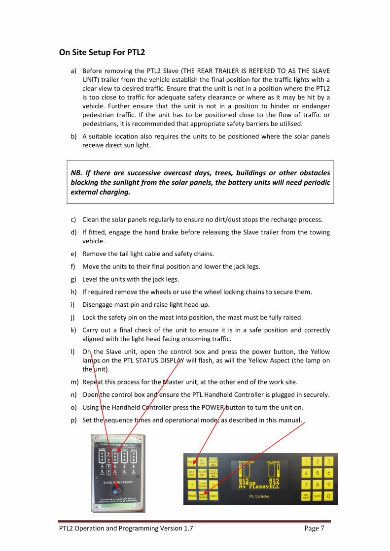
l) On the Slave unit, open the control box and press the power button, the Yellow lamps on the PTL STATUS DISPLAY will flash, as will the Yellow Aspect (the lamp on the unit).
m) Repeat this process for the Master unit, at the other end of the work site.
n) Open the control box and ensure the PTL Handheld Controller is plugged in securely.
o) Using the Handheld Controller press the POWER button to turn the unit on.
p) Set the sequence times and operational mode, as described in this manual.
PTL2 Operation and Programming Version 1.7 Page 8
On Site Pack Up For PTL2 PICK UP THE MASTER UNIT FIRST
a) Turn off the PTL2 Master unit by pressing the POWER button on the PTL Controller, located in the control box. To turn off the Slave unit the system must be in Flash Yellow mode, and then press the POWER button on the STATUS DISPLAY unit on the control box.
b) Ensure that the wheels are properly fitted and wheel nuts correctly tightened.
c) Check that the hand brake is engaged (if fitted) and any wheel locks are removed and stowed.
d) Release the mast locking pin and lower the lamp head.
e) Raise jack legs and swivel into the transport position.
f) Lower the trailer to the towing vehicle (using jockey wheel).
g) Ensure the tow hitch is properly fitted to the tow ball of the towing vehicle and the latch is in the locked position.
h) Connect safety chain/s and 7 pin connecter.
i) Raise and swivel jockey wheel to transport position.
j) It is recommended that the handles for the jockey wheel and jack legs be rotated to “sit” on the trailer frame and not left hanging down.
k) Release hand brake (if fitted).
l) Check tail lights are operating correctly.
m) Check all legs and jockey wheel swivels have locked into position correctly.
n) PICK UP THE SLAVE UNIT NEXT.
o) Follow the procedure listed above.
p) Refer to the section “Joining & Separating PTL2 Trailers”.
PTL2 Operation and Programming Version 1.7 Page 9
MODES OF OPERATION
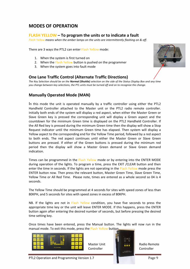
FLASH YELLOW – To program the units or to indicate a fault Flash Yellow means when the amber lamps on the units are intermittently flashing on & off.
There are 3 ways the PTL2 can enter Flash Yellow mode:
1. When the system is first turned on 2. When the Flash Yellow button is pushed on the programmer 3. When the system goes into fault mode
One Lane Traffic Control (Alternate Traffic Directions) The Key Selection should be on the Normal (Shuttle) selection on the side of the Status Display Box and any time you change between key selections, the PTL units must be turned off and on to recognize the change.
Manually Operated Mode (MAN)
In this mode the unit is operated manually by a traffic controller using either the PTL2
Handheld Controller attached to the Master unit or the PTL2 radio remote controller. Initially both ends of the system will display a red aspect, when either the Master Green or Slave Green key is pressed the corresponding unit will display a Green aspect and the countdown for the minimum Green time is displayed on the PTL2 Handheld Controller. If the All Red key is pressed during the minimum Green time then the display will show a Stop Request indicator until the minimum Green time has elapsed. Then system will display a Yellow aspect to the corresponding end for the Yellow Time period, followed by a red aspect to both ends. The red aspect continues until either the Master Green or Slave Green buttons are pressed. If either of the Green buttons is pressed during the minimum red period then the display will show a Master Green demand or Slave Green demand indication. Times can be programmed in the Flash Yellow mode or by entering into the ENTER MODE during operation of the lights. To program a time, press the EXIT /CLEAR button and then enter the time in seconds. If the lights are not operating in the Flash Yellow mode press the ENTER button now. Then press the relevant button, Master Green Time, Slave Green Time, Yellow Time or All Red Time. Please note, times are entered as a whole second so 04 is 4 seconds. The Yellow Time should be programmed at 4 seconds for sites with speed zones of less than 80KPH, and 5 seconds for sites with speed zones in excess of 80KPH. NB. If the lights are not in Flash Yellow condition, you have five seconds to press the appropriate time key or the unit will leave ENTER MODE. If this happens, press the ENTER button again after entering the desired number of seconds, but before pressing the desired time setting key. Once times have been entered, press the Manual button. The lights will now run in the manual mode. To exit this mode, press the Flash Yellow button.
Master Unit Controller
Radio Remote Controller
PTL2 Operation and Programming Version 1.7 Page 10
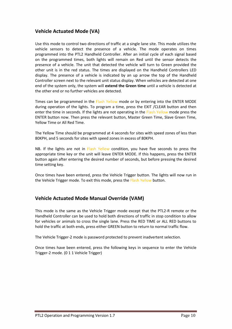
Vehicle Actuated Mode (VA) Use this mode to control two directions of traffic at a single lane site. This mode utilizes the vehicle sensors to detect the presence of a vehicle. The mode operates on times programmed into the PTL2 Handheld Controller. After an initial cycle of each signal based on the programmed times, both lights will remain on Red until the sensor detects the presence of a vehicle. The unit that detected the vehicle will turn to Green provided the other unit is in the red status. The times are displayed on the Handheld Controllers LED display. The presence of a vehicle is indicated by an up arrow the top of the Handheld Controller screen next to the relevant unit status display. When vehicles are detected at one end of the system only, the system will extend the Green time until a vehicle is detected at the other end or no further vehicles are detected. Times can be programmed in the Flash Yellow mode or by entering into the ENTER MODE during operation of the lights. To program a time, press the EXIT /CLEAR button and then enter the time in seconds. If the lights are not operating in the Flash Yellow mode press the ENTER button now. Then press the relevant button, Master Green Time, Slave Green Time, Yellow Time or All Red Time. The Yellow Time should be programmed at 4 seconds for sites with speed zones of less than 80KPH, and 5 seconds for sites with speed zones in excess of 80KPH. NB. If the lights are not in Flash Yellow condition, you have five seconds to press the appropriate time key or the unit will leave ENTER MODE. If this happens, press the ENTER button again after entering the desired number of seconds, but before pressing the desired time setting key. Once times have been entered, press the Vehicle Trigger button. The lights will now run in the Vehicle Trigger mode. To exit this mode, press the Flash Yellow button.
Vehicle Actuated Mode Manual Override (VAM) This mode is the same as the Vehicle Trigger mode except that the PTL2-R remote or the Handheld Controller can be used to hold both directions of traffic in stop condition to allow for vehicles or animals to cross the single lane. Press the RED TIME or ALL RED buttons to hold the traffic at both ends, press either GREEN button to return to normal traffic flow. The Vehicle Trigger-2 mode is password protected to prevent inadvertent selection. Once times have been entered, press the following keys in sequence to enter the Vehicle Trigger-2 mode. (0 1 1 Vehicle Trigger)
PTL2 Operation and Programming Version 1.7 Page 11
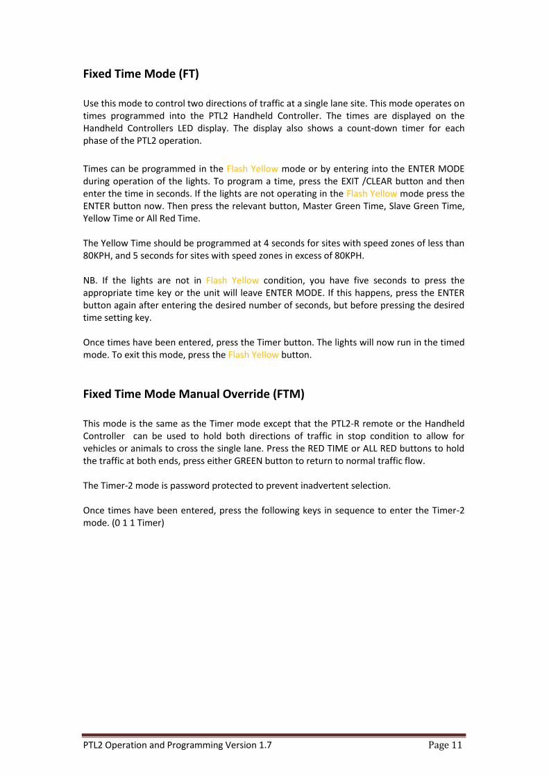
Fixed Time Mode (FT) Use this mode to control two directions of traffic at a single lane site. This mode operates on times programmed into the PTL2 Handheld Controller. The times are displayed on the Handheld Controllers LED display. The display also shows a count-down timer for each phase of the PTL2 operation.
Times can be programmed in the Flash Yellow mode or by entering into the ENTER MODE during operation of the lights. To program a time, press the EXIT /CLEAR button and then enter the time in seconds. If the lights are not operating in the Flash Yellow mode press the ENTER button now. Then press the relevant button, Master Green Time, Slave Green Time, Yellow Time or All Red Time. The Yellow Time should be programmed at 4 seconds for sites with speed zones of less than 80KPH, and 5 seconds for sites with speed zones in excess of 80KPH. NB. If the lights are not in Flash Yellow condition, you have five seconds to press the appropriate time key or the unit will leave ENTER MODE. If this happens, press the ENTER button again after entering the desired number of seconds, but before pressing the desired time setting key. Once times have been entered, press the Timer button. The lights will now run in the timed mode. To exit this mode, press the Flash Yellow button.
Fixed Time Mode Manual Override (FTM) This mode is the same as the Timer mode except that the PTL2-R remote or the Handheld Controller can be used to hold both directions of traffic in stop condition to allow for vehicles or animals to cross the single lane. Press the RED TIME or ALL RED buttons to hold the traffic at both ends, press either GREEN button to return to normal traffic flow. The Timer-2 mode is password protected to prevent inadvertent selection. Once times have been entered, press the following keys in sequence to enter the Timer-2 mode. (0 1 1 Timer)
PTL2 Operation and Programming Version 1.7 Page 12
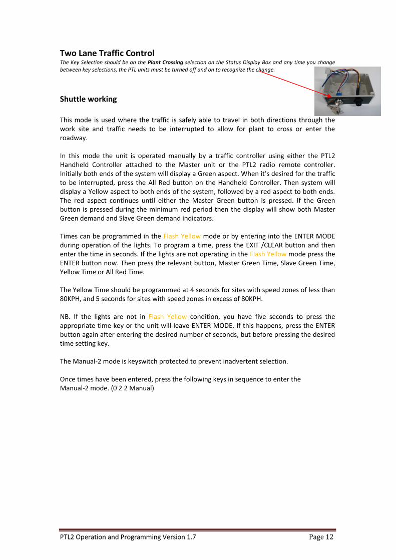
Two Lane Traffic Control The Key Selection should be on the Plant Crossing selection on the Status Display Box and any time you change between key selections, the PTL units must be turned off and on to recognize the change.
Shuttle working
This mode is used where the traffic is safely able to travel in both directions through the work site and traffic needs to be interrupted to allow for plant to cross or enter the roadway. In this mode the unit is operated manually by a traffic controller using either the PTL2 Handheld Controller attached to the Master unit or the PTL2 radio remote controller. Initially both ends of the system will display a Green aspect. When it’s desired for the traffic to be interrupted, press the All Red button on the Handheld Controller. Then system will display a Yellow aspect to both ends of the system, followed by a red aspect to both ends. The red aspect continues until either the Master Green button is pressed. If the Green button is pressed during the minimum red period then the display will show both Master Green demand and Slave Green demand indicators. Times can be programmed in the Flash Yellow mode or by entering into the ENTER MODE during operation of the lights. To program a time, press the EXIT /CLEAR button and then enter the time in seconds. If the lights are not operating in the Flash Yellow mode press the ENTER button now. Then press the relevant button, Master Green Time, Slave Green Time, Yellow Time or All Red Time. The Yellow Time should be programmed at 4 seconds for sites with speed zones of less than 80KPH, and 5 seconds for sites with speed zones in excess of 80KPH. NB. If the lights are not in Flash Yellow condition, you have five seconds to press the appropriate time key or the unit will leave ENTER MODE. If this happens, press the ENTER button again after entering the desired number of seconds, but before pressing the desired time setting key. The Manual-2 mode is keyswitch protected to prevent inadvertent selection. Once times have been entered, press the following keys in sequence to enter the Manual-2 mode. (0 2 2 Manual)

PTL2 Operation and Programming Version 1.7 Page 13
Vehicle Trigger 3-Way (If Enabled) This mode is used to independently control three individual flows of traffic. This mode is set-up using 3 units: Master, Slave 1 & Slave 2. Any unit (either a standard Master or Slave) can be programmed to be a Slave 2. To program a unit to become a Slave 2, plug the hand controller into the Status Display (located in the control box on the trailer base). Turn the unit on, type 331, then press the Setup Button. Turn the unit off with the hand controller (do not unplug the hand controller at this stage). Turn the unit on again, this time using the push button on the Status Display. The unit will now be set as Slave 2. This can be confirmed by viewing the hand controller, which will indicate the unit is now Slave 2. The hand controller can now be removed for programming the Master unit. Turn Slave 1 on as usual (no programming required) using the button on the Status Display. Turn the Master unit on with the hand controller. Type 331 and press the Setup Button. The hand controller will now display the 3 lights on the screen. NB. All units need to be set to the same radio channel. To exit 3 Way Mode (on the Master & Slave 2 units) type 330, then press the Setup Button. Times can be programmed in the Flash Yellow mode or by entering into the ENTER MODE during operation of the lights. To program a time, press the EXIT /CLEAR button and then enter the time in seconds. If the lights are not operating in the YELLOW FLASH mode press the ENTER button now. Then press the relevant button, Master Green Time, Slave Green Time, Yellow Time or All Red Time. To program the Green Time for Slave 2 press the F2 button. The Yellow Time should be programmed at 4 seconds for sites with speed zones of less than 80KPH, and 5 seconds for sites with speed zones in excess of 80KPH. NB. If the lights are not in FLASH YELLOW condition, you have five seconds to press the appropriate time key or the unit will leave ENTER MODE. If this happens, press the ENTER button again after entering the desired number of seconds, but before pressing the desired time setting key. NB: The vehicle detectors MUST be faced away from the roadway toward the direction of approaching plant that will trigger the interruption of traffic flow. It is important that the operator of the plant are aware that the system in displaying red to the oncoming traffic only when the rear amber lamp is flashing.
PTL2 Operation and Programming Version 1.7 Page 14
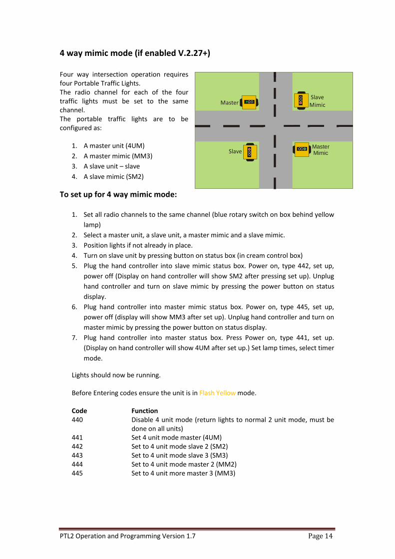
4 way mimic mode (if enabled V.2.27+) Four way intersection operation requires four Portable Traffic Lights. The radio channel for each of the four traffic lights must be set to the same channel. The portable traffic lights are to be configured as:
1. A master unit (4UM)
2. A master mimic (MM3)
3. A slave unit – slave
4. A slave mimic (SM2)
To set up for 4 way mimic mode:
1. Set all radio channels to the same channel (blue rotary switch on box behind yellow
lamp)
2. Select a master unit, a slave unit, a master mimic and a slave mimic.
3. Position lights if not already in place.
4. Turn on slave unit by pressing button on status box (in cream control box)
5. Plug the hand controller into slave mimic status box. Power on, type 442, set up,
power off (Display on hand controller will show SM2 after pressing set up). Unplug
hand controller and turn on slave mimic by pressing the power button on status
display.
6. Plug hand controller into master mimic status box. Power on, type 445, set up,
power off (display will show MM3 after set up). Unplug hand controller and turn on
master mimic by pressing the power button on status display.
7. Plug hand controller into master status box. Press Power on, type 441, set up.
(Display on hand controller will show 4UM after set up.) Set lamp times, select timer
mode.
Lights should now be running. Before Entering codes ensure the unit is in Flash Yellow mode. Code Function 440 Disable 4 unit mode (return lights to normal 2 unit mode, must be
done on all units) 441 Set 4 unit mode master (4UM) 442 Set to 4 unit mode slave 2 (SM2) 443 Set to 4 unit mode slave 3 (SM3) 444 Set to 4 unit mode master 2 (MM2) 445 Set to 4 unit more master 3 (MM3)
Slave MimicMaster
SlaveMaster Mimic
PTL2 Operation and Programming Version 1.7 Page 15
Reset the lights to normal operation. To reset lights to normal operation power each light off, Plug in the hand controller, Press ‘power on’, Type 440, set up. The lamp will now be in normal operating mode.
To set a time: (all times are set from master unit)
Times can be programmed in the Flash Yellow mode or by entering into the ENTER MODE during operation of the lights. To program a time, press the EXIT /CLEAR button and then enter the time in seconds. If the lights are not operating in the Flash Yellow mode press the ENTER button now. Then press the relevant button, Master Green Time, Slave Green Time, Yellow Time or All Red Time. The Yellow Time should be programmed at 4 seconds for sites with speed zones of less than 80KPH, and 5 seconds for sites with speed zones in excess of 80KPH. NB. If the lights are not in Flash Yellow condition, you have five seconds to press the appropriate time key or the unit will leave ENTER MODE. If this happens, press the ENTER button again after entering the desired number of seconds, but before pressing the desired time setting key. The times for the green light in each of the main and the cross road can be configured to allow a minimum green time.
1. Press ‘enter’
2. Enter the desired time in seconds using the number keys
3. Press the key for the time you with to set
The red time key will set the red time for both lights. The master green time key will set the minimum green time for the master lights The slave green time will set the minimum green time for the slave lights.
Fault Modes If any condition exists that would cause confusion to the approaching traffic or a failure condition exists, the unit will automatically revert to Flash Yellow mode. An SMS message will be sent to the pre-programmed phone number if the SMS system is installed (optional). The bottom line of the Handheld Controller screen will show the failure detected. Rectify the failure and then press the EXIT /CLEAR button to clear the fault display.
PTL2 Operation and Programming Version 1.7 Page 16
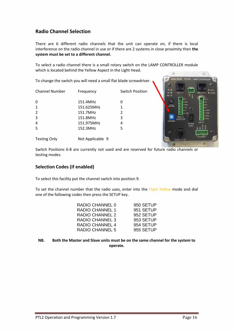
Radio Channel Selection There are 6 different radio channels that the unit can operate on, if there is local interference on the radio channel in use or if there are 2 systems in close proximity then the system must be set to a different channel. To select a radio channel there is a small rotary switch on the LAMP CONTROLLER module which is located behind the Yellow Aspect in the Light Head. To change the switch you will need a small flat blade screwdriver. Channel Number Frequency Switch Position 0 151.4MHz 0 1 151.625MHz 1 2 151.7MHz 2 3 151.8MHz 3 4 151.975MHz 4 5 152.3MHz 5 Testing Only Not Applicable 9 Switch Positions 6-8 are currently not used and are reserved for future radio channels or testing modes.
Selection Codes (if enabled) To select this facility put the channel switch into position 9. To set the channel number that the radio uses, enter into the Flash Yellow mode and dial one of the following codes then press the SETUP key.
RADIO CHANNEL 0 950 SETUP
RADIO CHANNEL 1 951 SETUP
RADIO CHANNEL 2 952 SETUP RADIO CHANNEL 3 953 SETUP
RADIO CHANNEL 4 954 SETUP
RADIO CHANNEL 5 955 SETUP
NB. Both the Master and Slave units must be on the same channel for the system to
operate.

PTL2 Operation and Programming Version 1.7 Page 17
SMS Reporting The System can send an SMS message when any failure event occurs; the message contains the Plant Number of the unit and a description of the fault along with the battery voltage of both the Master and Slave units.
Setting the Phone Number To set the Phone number that the system sends the error messages to, enter into the Flash Yellow mode and dial 982 then press the SETUP key. The screen will show that the Enter Phone number mode is active. Then simply type the number that the SMS reports are to be sent to and press the ENTER key. If you make an error or wish to clear the old number press the EXIT/CLEAR key and start again.
Testing the SMS System To send a test SMS message enter the Flash Yellow mode and dial 997 then press the SETUP key. 997 SETUP Send Test SMS
Setting the Plant Number To set the Plant number that the PTL2 sends in the SMS messages enter the Flash Yellow mode and dial 981 then press the SETUP key. The screen will show that the Enter Plant Number mode is active. Then simply type the Plant number of the unit and press the ENTER key. If you make an error or wish to clear the old number press the EXIT/CLEAR and start again.
PTL2 Operation and Programming Version 1.7 Page 18
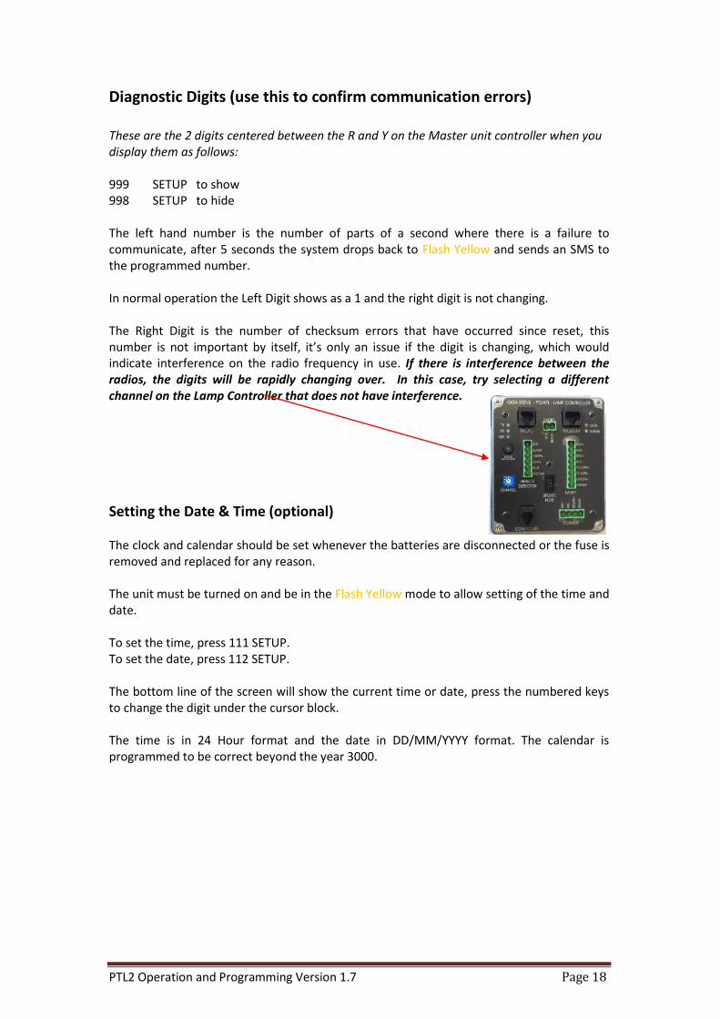
Diagnostic Digits (use this to confirm communication errors) These are the 2 digits centered between the R and Y on the Master unit controller when you display them as follows: 999 SETUP to show 998 SETUP to hide The left hand number is the number of parts of a second where there is a failure to communicate, after 5 seconds the system drops back to Flash Yellow and sends an SMS to the programmed number. In normal operation the Left Digit shows as a 1 and the right digit is not changing. The Right Digit is the number of checksum errors that have occurred since reset, this number is not important by itself, it’s only an issue if the digit is changing, which would indicate interference on the radio frequency in use. If there is interference between the radios, the digits will be rapidly changing over. In this case, try selecting a different channel on the Lamp Controller that does not have interference.
Setting the Date & Time (optional) The clock and calendar should be set whenever the batteries are disconnected or the fuse is removed and replaced for any reason. The unit must be turned on and be in the Flash Yellow mode to allow setting of the time and date. To set the time, press 111 SETUP. To set the date, press 112 SETUP. The bottom line of the screen will show the current time or date, press the numbered keys to change the digit under the cursor block. The time is in 24 Hour format and the date in DD/MM/YYYY format. The calendar is programmed to be correct beyond the year 3000.

PTL2 Operation and Programming Version 1.7 Page 19
Normal Values for All Red Time
TRAVEL DISTANCE (metres)
RELATIONSHIP BETWEEN ALL-RED CLEARANCE TIME ANDTRAVEL DISTANCE FOR A RANGE OF VEHICLE SPEEDS
100
0 100
60km/h
50km/h
40km/h
30km/h20km/h10km/h
200 300 400 500 600 700 800 900 1000
90
80
70
60
50
40
30
20
10
0
PTL2 Operation and Programming Version 1.7 Page 20
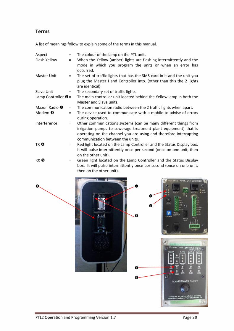
Terms A list of meanings follow to explain some of the terms in this manual. Aspect = The colour of the lamp on the PTL unit. Flash Yellow = When the Yellow (amber) lights are flashing intermittently and the
mode in which you program the units or when an error has occurred.
Master Unit = The set of traffic lights that has the SMS card in it and the unit you plug the Master Hand Controller into. (other than this the 2 lights are identical)
Slave Unit = The secondary set of traffic lights. Lamp Controller = The main controller unit located behind the Yellow lamp in both the
Master and Slave units. Maxon Radio = The communication radio between the 2 traffic lights when apart. Modem = The device used to communicate with a mobile to advise of errors
during operation. Interference = Other communications systems (can be many different things from
irrigation pumps to sewerage treatment plant equipment) that is operating on the channel you are using and therefore interrupting communication between the units.
TX = Red light located on the Lamp Controller and the Status Display box. It will pulse intermittently once per second (once on one unit, then on the other unit).
RX = Green light located on the Lamp Controller and the Status Display box. It will pulse intermittently once per second (once on one unit, then on the other unit).

PTL2 Operation and Programming Version 1.7 Page 21
Troubleshooting The fault condition will be shown on the hand-controller display along the bottom line. BATTERY ERRORS If there have been a few overcast days in succession or the lights have been parked in a shaded area continuously, you can expect a low battery warning, this is normal. At the first low battery warning, it is recommended to recharge or swap the batteries over. However, if you receive a battery critical warning, it is imperative that the batteries are recharged immediately, or else you risk damaging the battery life permanently. ERRSBATLOW = Slave Battery Low ERRMBATLOW = Master Battery Low ERRSBATCRIT = Slave Battery Critical ERRMBATCRIT = Master Battery Critical ERRSBATFLAT = Slave Battery Flat ERRMBATFLAT = Master Battery Flat NB: When batteries are flat, the units will enter into Flash Yellow mode. LAMP ERRORS When there is a lamp error, the units will enter into Flash Yellow mode. LAMPERRSGRN = Slave Green Lamp Error LAMPERRSYEL = Slave Yellow Lamp Error LAMPERRSRED = Slave Red Lamp Error LAMPERRSAUX = Slave Auxiliary Lamp Error (at the rear of the traffic light head) LAMPERRMGRN = Master Green Lamp Error LAMPERRMYEL = Master Yellow Lamp Error LAMPERRMRED = Master Red Lamp Error LAMPERRMAUX = Master Auxiliary Lamp Error (at the rear of the traffic light head) When a lamp error occurs, open the Yellow lamp cover on the appropriate unit (Slave or Master) and press and hold the lamp test button to confirm the lamp fault. If the lamp does not illuminate, then there is a fault. In the case of a confirmed fault:
a) Open the faulty lamp cover and locate the reset push button on the driver board (on the inside of the lamp module) and press briefly whilst holding the lamp test button.
b) If the lamp does not illuminate, check the wiring from the processor unit to the lamp.
c) If the fault continues, the lamp needs replacement. Contact LDC service on 0438 193 294 stating fault code #1a

PTL2 Operation and Programming Version 1.7 Page 22
COMMUNICATION ERRORS ERRCOMSLAVE = Communication between the Master and Slave units has been
broken for more than 5 seconds continuously and they are now in Flash Yellow mode.
The lights will try to re-establish communication for 5 minutes once a COMSLAVE error has occurred. If successful, the lights will resume normal operation. The error code will remain on the screen until the clear button is pressed, even when back to normal operation. If the lights remain in Flash Yellow mode, this means the communication between the Master and Slave units has malfunctioned. In this situation:
a) Check the Slave is turned ON b) Check the Antenna/s are intact c) Ensure the Master and Slave units are on the same frequency channel d) If a radio scanner is available, you can listen for other signals using the same radio
frequency to confirm interference. (you may not always be able to ascertain the actual interference, if in the case that it is an intermittent signal).
Diagnosing the Communication Errors
1. Look for the TX RX lights on the Master 2. Look for the RX TX lights on the Slave
If the TX is blinking on the Master, yet the RX is NOT blinking on the Slave, it indicates a likely radio transmitter fault. In this situation:
a) Open the Red Lamp on the Master to check for the light on the Maxon radio. If it is blinking red in synchronization of the TX lamp, this indicates that it is attempting to transmit. i) If it’s not blinking red, but on steady amber, then the data cable between the lamp controller and the maxon radio is either not correctly connected or the cable or lamp controller are faulty. Contact LDC Service quoting the fault code #2a. ii) If there is no light on the radio, then ensure the red and black power cable between the bottom of the radio and the front of the lamp controller is connected. If the fault continues, contact LDC Service quoting the fault code #2b.