le-200ps le-150ps le-200ps - hardware protocol … · product as explained in that manual. ......
TRANSCRIPT
*The photo is for illustrative purposes only.
®
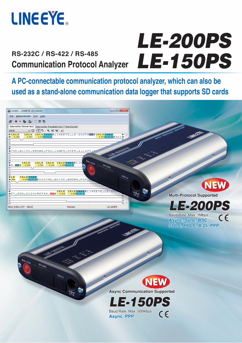
A PC-connectable communication protocol analyzer, which can also be used as a stand-alone communication data logger that supports SD cards
•All brand names and product names mentioned in this catalog are trademarks or registered trademarks of their respective companies. •Specifications and designs of products listed in this catalog are as of February 2012, and are subject to change without notice for improvement. •Colors of actual products may differ slightly from that listed due to printing condition. •This catalog may not be reprinted or duplicated, in part or in whole.©2012 by LINEEYE CO., LTD.
* LINEEYE CO., LTD. is a venture company founded by electronic equipment development members of the former Sekisui Chemical Co., Ltd. with investment from the Sekisui Venture Fund.
Printed in Japan
L-12202E/LE G
LINEEYE CO., LTD.Head Office/Sales Office Marufuku Bldg, 5F, 39-1 Karahashi Nishihiragaki-cho, Minami-ku, Kyoto, 601-8468 PHONE: 81-75-693-0161 FAX:81-75-693-0163
URL http://www.lineeye.comE-mail : [email protected]
Read the instruction manual provided with the product before use and use the product as explained in that manual. Using the product in ways not guaranteed in the manual, connecting it to systems outside of the specified ranges and remodeling can all cause trouble and damage. LINEEYE CO., LTD. will assume no responsibility whatsoever for trouble or damage arising because of unauthorized ways of use.
SAFETYWARNING
QR-00337ER-00094
LE-200PSLE-150PSCommunication Protocol Analyzer
Async Communication SupportedAsync Communication Supported
Async, PPPAsync, PPPBaud Rate: Max. 500KbpsBaud Rate: Max. 500Kbps
LE-150PSLE-150PS
Multi-Protocol SupportedMulti-Protocol Supported
Async, Sync, BSC, Async, Sync, BSC, SDLC, HDLC, X.25, PPPSDLC, HDLC, X.25, PPP
Baud Rate: Max. 1MbpsBaud Rate: Max. 1Mbps
LE-200PSLE-200PS
Async Communication Supported
Async, PPPBaud Rate: Max. 500Kbps
LE-150PS
Multi-Protocol Supported
Async, Sync, BSC, SDLC, HDLC, X.25, PPP
Baud Rate: Max. 1Mbps
LE-200PS
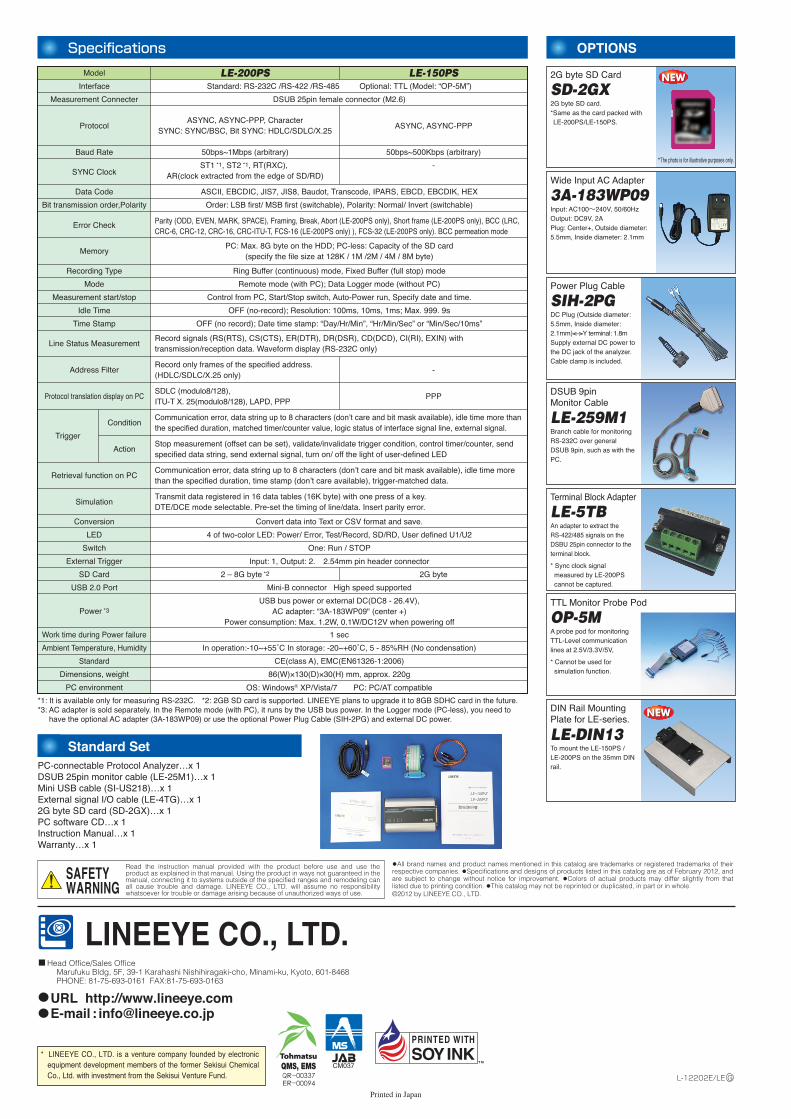
Specifications OPTIONS
SD-2GX
*1: It is available only for measuring RS-232C. *2: 2GB SD card is supported. LINEEYE plans to upgrade it to 8GB SDHC card in the future.*3: AC adapter is sold separately. In the Remote mode (with PC), it runs by the USB bus power. In the Logger mode (PC-less), you need to
have the optional AC adapter (3A-183WP09) or use the optional Power Plug Cable (SIH-2PG) and external DC power.
2G byte SD Card
3A-183WP09Wide Input AC Adapter
SIH-2PGPower Plug Cable
LE-259M1
DSUB 9pin Monitor Cable
LE-5TBTerminal Block Adapter
OP-5MTTL Monitor Probe Pod
LE-DIN13
DIN Rail Mounting Plate for LE-series.
Model LE-200PS LE-150PS
Measurement Connecter
Protocol
Baud Rate
SYNC Clock
Data Code
Bit transmission order,Polarity
Error Check
Memory
Recording Type
Mode
Measurement start/stop
Idle Time
Time Stamp
Line Status Measurement
DSUB 25pin female connector (M2.6)
ASYNC, ASYNC-PPP, Character SYNC: SYNC/BSC, Bit SYNC: HDLC/SDLC/X.25
ASYNC, ASYNC-PPP
50bps~1Mbps (arbitrary) 50bps~500Kbps (arbitrary)
ST1 *1, ST2 *1, RT(RXC), AR(clock extracted from the edge of SD/RD)
-
ASCII, EBCDIC, JIS7, JIS8, Baudot, Transcode, IPARS, EBCD, EBCDIK, HEX
Order: LSB first/ MSB first (switchable), Polarity: Normal/ Invert (switchable)
Ring Buffer (continuous) mode, Fixed Buffer (full stop) mode
Remote mode (with PC); Data Logger mode (without PC)
Control from PC, Start/Stop switch, Auto-Power run, Specify date and time.
OFF (no-record); Resolution: 100ms, 10ms, 1ms; Max. 999. 9s
OFF (no record); Date time stamp: “Day/Hr/Min”, “Hr/Min/Sec” or “Min/Sec/10ms”
Conversion Convert data into Text or CSV format and save.
LED 4 of two-color LED: Power/ Error, Test/Record, SD/RD, User defined U1/U2
Switch One: Run / STOP
External Trigger Input: 1, Output: 2. 2.54mm pin header connector
2 – 8G byte *2 2G byteSD Card
USB 2.0 Port Mini-B connector High speed supported
1 sec
In operation:-10~+55˚C In storage: -20~+60˚C, 5 - 85%RH (No condensation)
86(W)×130(D)×30(H) mm, approx. 220g
OS: Windows® XP/Vista/7 PC: PC/AT compatible
Power *3
USB bus power or external DC(DC8 - 26.4V),AC adapter: “3A-183WP09" (center +)
Power consumption: Max. 1.2W, 0.1W/DC12V when powering off
Work time during Power failure
Ambient Temperature, Humidity
Standard
Dimensions, weight
PC environment
Communication error, data string up to 8 characters (don’t care and bit mask available), idle time more than the specified duration, time stamp (don’t care available), trigger-matched data.
Record signals (RS(RTS), CS(CTS), ER(DTR), DR(DSR), CD(DCD), CI(RI), EXIN) with transmission/reception data. Waveform display (RS-232C only)
Communication error, data string up to 8 characters (don’t care and bit mask available), idle time more than the specified duration, matched timer/counter value, logic status of interface signal line, external signal.
Stop measurement (offset can be set), validate/invalidate trigger condition, control timer/counter, send specified data string, send external signal, turn on/ off the light of user-defined LED
Address Filter
Trigger
Action
Condition
Protocol translation display on PC
Transmit data registered in 16 data tables (16K byte) with one press of a key.DTE/DCE mode selectable. Pre-set the timing of line/data. Insert parity error.
Record only frames of the specified address. (HDLC/SDLC/X.25 only)
-
SDLC (modulo8/128), ITU-T X. 25(modulo8/128), LAPD, PPP
PPP
Parity (ODD, EVEN, MARK, SPACE), Framing, Break, Abort (LE-200PS only), Short frame (LE-200PS only), BCC (LRC, CRC-6, CRC-12, CRC-16, CRC-ITU-T, FCS-16 (LE-200PS only) ), FCS-32 (LE-200PS only). BCC permeation mode
PC: Max. 8G byte on the HDD; PC-less: Capacity of the SD card(specify the file size at 128K / 1M /2M / 4M / 8M byte)
Interface Standard: RS-232C /RS-422 /RS-485 Optional: TTL (Model: “OP-5M”)
Input: AC100~240V, 50/60HzOutput: DC9V, 2APlug: Center+, Outside diameter: 5.5mm, Inside diameter: 2.1mm
DC Plug (Outside diameter: 5.5mm, Inside diameter: 2.1mm)<–>Y terminal: 1.8mSupply external DC power to the DC jack of the analyzer. Cable clamp is included.
Branch cable for monitoring RS-232C over general DSUB 9pin, such as with the PC.
An adapter to extract the RS-422/485 signals on the DSBU 25pin connector to the terminal block.
* Sync clock signal measured by LE-200PS cannot be captured.
2G byte SD card.*Same as the card packed with LE-200PS/LE-150PS.
A probe pod for monitoring TTL-Level communication lines at 2.5V/3.3V/5V,
* Cannot be used for simulation function.
To mount the LE-150PS / LE-200PS on the 35mm DIN rail.
RS-232C / RS-422 / RS-485
PC-connectable Protocol Analyzer…x 1DSUB 25pin monitor cable (LE-25M1)…x 1Mini USB cable (SI-US218)…x 1External signal I/O cable (LE-4TG)…x 12G byte SD card (SD-2GX)…x 1PC software CD…x 1Instruction Manual…x 1Warranty…x 1
Standard Set
Simulation
Retrieval function on PC
CE(class A), EMC(EN61326-1:2006)
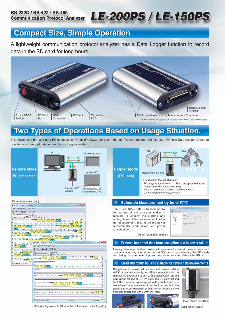
A lightweight communication protocol analyzer has a Data Logger function to record data in the SD card for long hours.
This device can be used as a PC-connectable Protocol Analyzer for use in the lab (Remote mode), and also as a PC-less Data Logger for use at
on-site tests to record data for long hours (Logger mode).
Measured data is saved as log files of the specified file size in the HDD of
the PC (Remote mode) or in the SD card of the analyzer (Logger mode).
It automatically records data until reaching the specified number of files,
and then deletes the oldest
file to record the new file. Also,
it can stop measurement on
reaching the specified number
of files. It is useful for
detecting any hindrance in
the line.
Long Hour Recording
Schedule Measurement by Inner RTC
Communication log files can be viewed
in detail on a PC. It offers seamless
operation that handles a single
measurement log file even when all
files are read collectively. The
measured data can be converted into
text or CSV format to use in a word
processor and/or spreadsheet software.
Seamless access to communication log files
Monitor data at any speed by setting the baud rate of any four digits.
The high-precision timer makes it possible to record idle time and time
stamps along with data, and is not related to the performance of the PC.
Measures at Arbitrary Speed.
It incorporates an easy-to-use simulation function that makes it possible
to transmit preset transmission data (16 types of data), or fixed data such
as FOX messages, at the flip of a key while checking reception data.
Easy-to-Operate Simulation Function
A newly developed instant power failure prevention circuit protects important communication log files stored in the SD cards, by protecting the SD cards from being corrupted even if power fails while recording data to the SD card.
Protects important data from corruption due to power failure
Small and robust housing suitable for severe field environments
[ Record Control Setting ]
*1: For attaching the optional DIN rail plate. Pitch: 70mm. Depth: 3.5mm (max).
RUN / STOPSwitch
SD CardSlot
USBConnector
DC Jack Two-color LED
Compact Size, Simple Operation
Two Types of Operations Based on Usage Situation.
Compact Size, Simple Operation
Two Types of Operations Based on Usage Situation.
The device comes standard with RS-232C/RS-422/RS-485 interfaces, which are used widely in medical equipment and electronic products. With an optional TTL probe pod (OP-5M), it can monitor TTL-level communication at 2.5V/ 3.3V/ 5V. LE-200PS can measure Sync communication, which has transmission/ reception clocks.
Supports RS-232C/RS-422/RS-485 (Standard Feature)
*1: A terminal-supplied power from analyzer. ON/OFF switchable.
*2: LE-5TB is useful for connecting the signals.*3: LE-200PS only.*4: Signal pins not defined here are not connected.
Signal
FG
RS-232C SD
RS-232C RD
RS-232C RS
RS-232C CS
RS-232C DR
GND *2
RS-232C CD
+5VDC *1
RS-422 RXDB+ *2
RS-422 RXDA- *2
RS-422 RXCB+ *3
RS-422 RXCA- *3
RS-232C ST2 *3
RS-232C RT *3
RS-422/485 TXDB+/TR+ *2
RS-422/485 TXDA-/TR- *2
RS-232C ER
RS-232C CI
RS-232C ST1 *3
Pin
1
2
3
4
5
6
7
8
9
10
11
12
13
15
17
18
19
20
22
24
Pin Assignment of Connector (DSUB 25 pin) [ Terminal Block Adapter (LE-5TB) ]
[ TTL Monitor Probe Pod (OP-5M) ]
[ Example of Simulation ]
[ Simulation Data Tables ]
[ Text Conversion Setting ]
RS-232C / RS-422 / RS-485Communication Protocol Analyzer
[ Recording Time ]
*: In the case of full-duplex transmission of 1K byte data at 1ms intervals.
Capacity: 1.8G byte (e.g. 4M byte×450 files)
Approx. 100 Hours
Approx. 4 Hours
Baud Rate
9600bps
230.4Kbps
Communication errors can be detected with high reliability.
It can judge parity error, framing error, BCC error of various block check
codes, and short SDLC/HDLC frame (LE-200PS only). It can find the
communication sequence in the event of an error, by setting an
application-level error notification character string to the character string
agreement criteria of the triggering function. It can notify an error to
external devices and alert a communication error in the logger mode
(with a panel LED lighting), by specifying an external trigger signal
output and user-defined LED lighting as a triggering action.
It is useful in the situations of:*PC usage is not allowed.*Dusty places (PC cannot be used).*Need to record data for more than one month.*Cannot operate the analyzer well
Logger Mode
(PC less)
*There are space limitations.
Record in the SD cardRemote Mode
(PC connected)
Real Time Clock (RTC) backed up by the battery of the analyzer makes it possible to specify the starting and ending times of the measurement. After the measurement, it turns off the power automatically and saves on power consumption.
PC Developing Device
Analysis PC
Connect to PC via USB Record in the HDD of PC
[ Dust-proof Covers ]
[ Data display example ]
[ Data display example (Control line information is displayed.) ]
[ Onto 35mm DIN Rail ]
[ Auto RUN/STOP setting ]
[ Configuration Setting ]
[ Trigger Setting ]
PLC Robot
M3 Screw Holes *1 Measurement Connector
External Signal Terminal
The palm-sized robust unit can be used between –10 to +55̊C. It operates not only on USB bus power, but also on external DC power of 8 to 26.4V. The consumption current is as low as 100mA at DC12V input. The SD card slot and the USB connector are equipped with a dust-proof cover that allows 2-way operation. It can be fixed easily to the equipment to be examined or built into an inspection line, since it is compatible with 35mm DIN rails.
RDSD
RDSD
*The photo is for illustrative purposes only.
®
A PC-connectable communication protocol analyzer, which can also be used as a stand-alone communication data logger that supports SD cards
•All brand names and product names mentioned in this catalog are trademarks or registered trademarks of their respective companies. •Specifications and designs of products listed in this catalog are as of February 2012, and are subject to change without notice for improvement. •Colors of actual products may differ slightly from that listed due to printing condition. •This catalog may not be reprinted or duplicated, in part or in whole.©2012 by LINEEYE CO., LTD.
* LINEEYE CO., LTD. is a venture company founded by electronic equipment development members of the former Sekisui Chemical Co., Ltd. with investment from the Sekisui Venture Fund.
Printed in Japan
L-12202E/LE G
LINEEYE CO., LTD.Head Office/Sales Office Marufuku Bldg, 5F, 39-1 Karahashi Nishihiragaki-cho, Minami-ku, Kyoto, 601-8468 PHONE: 81-75-693-0161 FAX:81-75-693-0163
URL http://www.lineeye.comE-mail : [email protected]
Read the instruction manual provided with the product before use and use the product as explained in that manual. Using the product in ways not guaranteed in the manual, connecting it to systems outside of the specified ranges and remodeling can all cause trouble and damage. LINEEYE CO., LTD. will assume no responsibility whatsoever for trouble or damage arising because of unauthorized ways of use.
SAFETYWARNING
QR-00337ER-00094
LE-200PSLE-150PSCommunication Protocol Analyzer
Async Communication SupportedAsync Communication Supported
Async, PPPAsync, PPPBaud Rate: Max. 500KbpsBaud Rate: Max. 500Kbps
LE-150PSLE-150PS
Multi-Protocol SupportedMulti-Protocol Supported
Async, Sync, BSC, Async, Sync, BSC, SDLC, HDLC, X.25, PPPSDLC, HDLC, X.25, PPP
Baud Rate: Max. 1MbpsBaud Rate: Max. 1Mbps
LE-200PSLE-200PS
Async Communication Supported
Async, PPPBaud Rate: Max. 500Kbps
LE-150PS
Multi-Protocol Supported
Async, Sync, BSC, SDLC, HDLC, X.25, PPP
Baud Rate: Max. 1Mbps
LE-200PS
Specifications OPTIONS
SD-2GX
*1: It is available only for measuring RS-232C. *2: 2GB SD card is supported. LINEEYE plans to upgrade it to 8GB SDHC card in the future.*3: AC adapter is sold separately. In the Remote mode (with PC), it runs by the USB bus power. In the Logger mode (PC-less), you need to
have the optional AC adapter (3A-183WP09) or use the optional Power Plug Cable (SIH-2PG) and external DC power.
2G byte SD Card
3A-183WP09Wide Input AC Adapter
SIH-2PGPower Plug Cable
LE-259M1
DSUB 9pin Monitor Cable
LE-5TBTerminal Block Adapter
OP-5MTTL Monitor Probe Pod
LE-DIN13
DIN Rail Mounting Plate for LE-series.
Model LE-200PS LE-150PS
Measurement Connecter
Protocol
Baud Rate
SYNC Clock
Data Code
Bit transmission order,Polarity
Error Check
Memory
Recording Type
Mode
Measurement start/stop
Idle Time
Time Stamp
Line Status Measurement
DSUB 25pin female connector (M2.6)
ASYNC, ASYNC-PPP, Character SYNC: SYNC/BSC, Bit SYNC: HDLC/SDLC/X.25
ASYNC, ASYNC-PPP
50bps~1Mbps (arbitrary) 50bps~500Kbps (arbitrary)
ST1 *1, ST2 *1, RT(RXC), AR(clock extracted from the edge of SD/RD)
-
ASCII, EBCDIC, JIS7, JIS8, Baudot, Transcode, IPARS, EBCD, EBCDIK, HEX
Order: LSB first/ MSB first (switchable), Polarity: Normal/ Invert (switchable)
Ring Buffer (continuous) mode, Fixed Buffer (full stop) mode
Remote mode (with PC); Data Logger mode (without PC)
Control from PC, Start/Stop switch, Auto-Power run, Specify date and time.
OFF (no-record); Resolution: 100ms, 10ms, 1ms; Max. 999. 9s
OFF (no record); Date time stamp: “Day/Hr/Min”, “Hr/Min/Sec” or “Min/Sec/10ms”
Conversion Convert data into Text or CSV format and save.
LED 4 of two-color LED: Power/ Error, Test/Record, SD/RD, User defined U1/U2
Switch One: Run / STOP
External Trigger Input: 1, Output: 2. 2.54mm pin header connector
2 – 8G byte *2 2G byteSD Card
USB 2.0 Port Mini-B connector High speed supported
1 sec
In operation:-10~+55˚C In storage: -20~+60˚C, 5 - 85%RH (No condensation)
86(W)×130(D)×30(H) mm, approx. 220g
OS: Windows® XP/Vista/7 PC: PC/AT compatible
Power *3
USB bus power or external DC(DC8 - 26.4V),AC adapter: “3A-183WP09" (center +)
Power consumption: Max. 1.2W, 0.1W/DC12V when powering off
Work time during Power failure
Ambient Temperature, Humidity
Standard
Dimensions, weight
PC environment
Communication error, data string up to 8 characters (don’t care and bit mask available), idle time more than the specified duration, time stamp (don’t care available), trigger-matched data.
Record signals (RS(RTS), CS(CTS), ER(DTR), DR(DSR), CD(DCD), CI(RI), EXIN) with transmission/reception data. Waveform display (RS-232C only)
Communication error, data string up to 8 characters (don’t care and bit mask available), idle time more than the specified duration, matched timer/counter value, logic status of interface signal line, external signal.
Stop measurement (offset can be set), validate/invalidate trigger condition, control timer/counter, send specified data string, send external signal, turn on/ off the light of user-defined LED
Address Filter
Trigger
Action
Condition
Protocol translation display on PC
Transmit data registered in 16 data tables (16K byte) with one press of a key.DTE/DCE mode selectable. Pre-set the timing of line/data. Insert parity error.
Record only frames of the specified address. (HDLC/SDLC/X.25 only)
-
SDLC (modulo8/128), ITU-T X. 25(modulo8/128), LAPD, PPP
PPP
Parity (ODD, EVEN, MARK, SPACE), Framing, Break, Abort (LE-200PS only), Short frame (LE-200PS only), BCC (LRC, CRC-6, CRC-12, CRC-16, CRC-ITU-T, FCS-16 (LE-200PS only) ), FCS-32 (LE-200PS only). BCC permeation mode
PC: Max. 8G byte on the HDD; PC-less: Capacity of the SD card(specify the file size at 128K / 1M /2M / 4M / 8M byte)
Interface Standard: RS-232C /RS-422 /RS-485 Optional: TTL (Model: “OP-5M”)
Input: AC100~240V, 50/60HzOutput: DC9V, 2APlug: Center+, Outside diameter: 5.5mm, Inside diameter: 2.1mm
DC Plug (Outside diameter: 5.5mm, Inside diameter: 2.1mm)<–>Y terminal: 1.8mSupply external DC power to the DC jack of the analyzer. Cable clamp is included.
Branch cable for monitoring RS-232C over general DSUB 9pin, such as with the PC.
An adapter to extract the RS-422/485 signals on the DSBU 25pin connector to the terminal block.
* Sync clock signal measured by LE-200PS cannot be captured.
2G byte SD card.*Same as the card packed with LE-200PS/LE-150PS.
A probe pod for monitoring TTL-Level communication lines at 2.5V/3.3V/5V,
* Cannot be used for simulation function.
To mount the LE-150PS / LE-200PS on the 35mm DIN rail.
RS-232C / RS-422 / RS-485
PC-connectable Protocol Analyzer…x 1DSUB 25pin monitor cable (LE-25M1)…x 1Mini USB cable (SI-US218)…x 1External signal I/O cable (LE-4TG)…x 12G byte SD card (SD-2GX)…x 1PC software CD…x 1Instruction Manual…x 1Warranty…x 1
Standard Set
Simulation
Retrieval function on PC
CE(class A), EMC(EN61326-1:2006)