le mans opti
TRANSCRIPT
Ferrari F458 GTInside Maranello’s GTE contender
Toyota TS030Designing the high tech hybrid
LE MANS
DeltaWingThe future of sportscar racing?
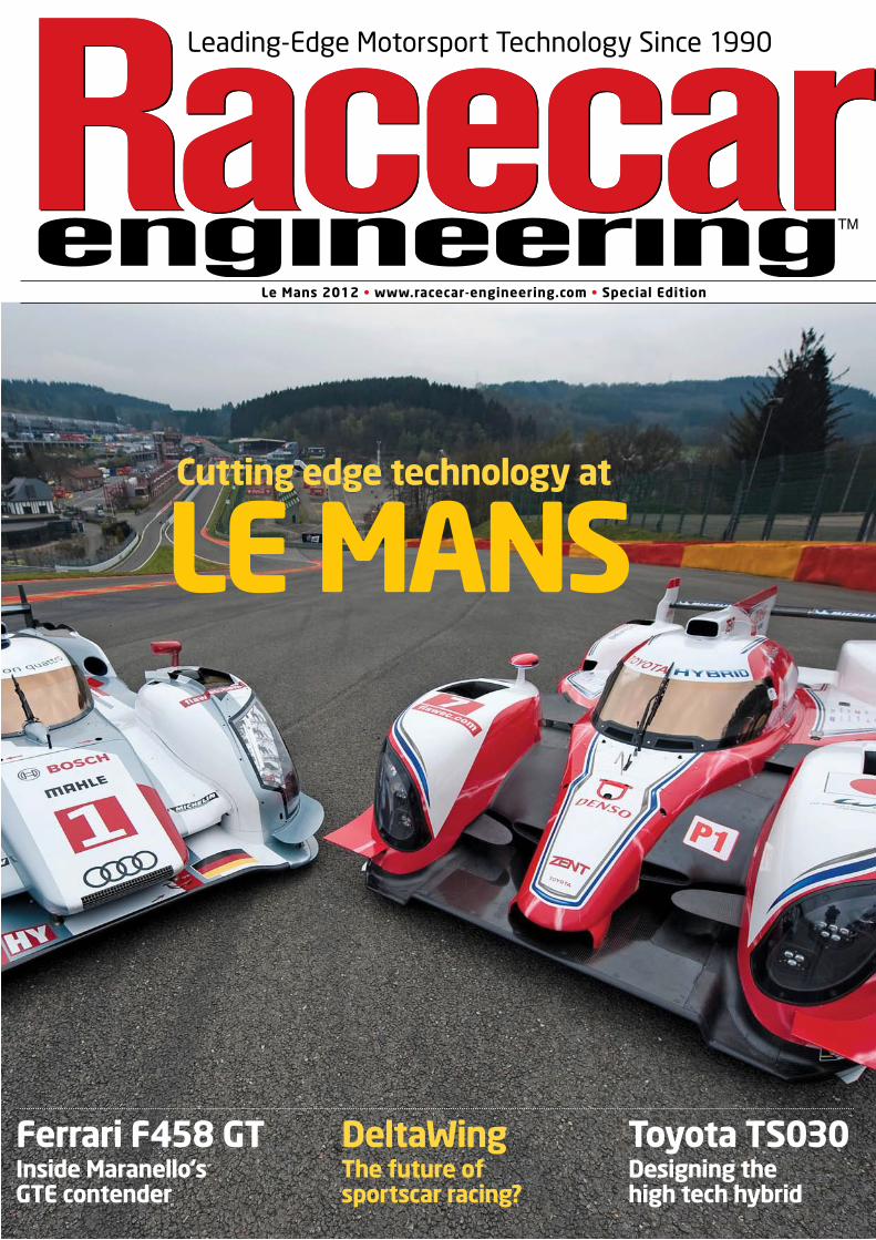
Cutting edge technology at
Leading-Edge Motorsport Technology Since 1990
Le Mans 2012 • www.racecar-engineering.com • Special Edition
Le Mans Cover 02.indd 1 28/05/2012 14:02
Lithionics Battery FP JUL12.indd 1 17/05/2012 11:25
Subscribe to Racecar Engineering – fi nd the best offers online www.racecar-engineering.com
Le Mans • www.racecar-engineering.com
CONTENTS – LE MANS EDITION
FEATURES
Toyota TS030The return of the Japanese manufacturer after a long-term evaluation of capacitor hybrid systems
Ferrari 458Taking a look at the latest Ferrari, originally designed for the now defunct GT1 category and adapted to GTEDome S101.5One of the most technically innovative manufacturers makes yet another evolution of a brilliant car
DeltaWing
A vision for the future? Lightweight design, effi cient aerodynamics and a 1.6-litre road car-derived engine
Open Source
DeltaWing designer, Ben Bowlby, on why he wants the
world to see the exact fi gures from his controversial project
HPD
Nick Wirth has come in for a lot of criticism for his design methods, but is he just a designer ahead of his time?
Aston Martin AMR-One
The car was a PR and competitive disaster, yet it will appear on this year’s Le Mans grid with Pescarolo and DeltaWing!
Nissan R90
We look back at the one that got away for Nissan
Le Mans 2011
Last year’s race was a battle of strategy, speed and true grit. We look back on how Le Mans was won last year
TECHNICAL
AerobytesUsing a real-world example to understand the impact of the 2012 ACO regulationsDeltaWing engineA new Nissan four-cylinder turbocharged race unit from British company, RML LMP wingsThe development of Prototype rear wings has taken some interesting turns
Flybrid KERSFinding the most effi cient way of keeping an LMP1 car stuck to the groundArchitecture of a dieselLooking at the development of Audi’s diesel engine, from V12 to V8 to V6
As the Le Mans 24 Hours steps into the future, we decided that now was a good time to look back at the major Sportscar stories featured in Racecar Engineering over the last 18 months.
From the Toyota TS030 to the DeltaWing and the Ferrari 458, we have featured the most exciting cars in detail. Technical innovation is at the heart of the Prototype classes, and we have also examined two of the most interesting developments in the last six years – KERS and diesel power.
Earlier this year, Greaves Motorsport allowed us to put its Zytek into the wind tunnel to test the effects of the 2012 aerodynamic modifi cations on a Le Mans Prototype. The results were enlightening.
We also take a look at rear wing innovations and delve into strategy, including a story on how the 2011 24 Hours was won, against the odds, by Audi.
If you like what you read here,take a look at the latest edition of Racecar Engineering. In it, you can read how we were granted exclusive access to a potential 2012 winner the world will never see, the Peugeot 908 HYbrid4. Our simulation expert, Danny Nowlan, discusses the effect of all-wheel drive on an LMP, and Sam Collins looks at how Sportscar teams are battling to re-direct airfl ow to their rear diffusers.
We hope you enjoy these pages, and future issues of Racecar Engineering, the magazine we consider to be the journal of motorsport technology.
WHAT’S INSIDE
Le Mans Contents-ACMP.indd 3 28/05/2012 10:35
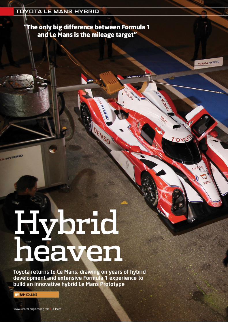
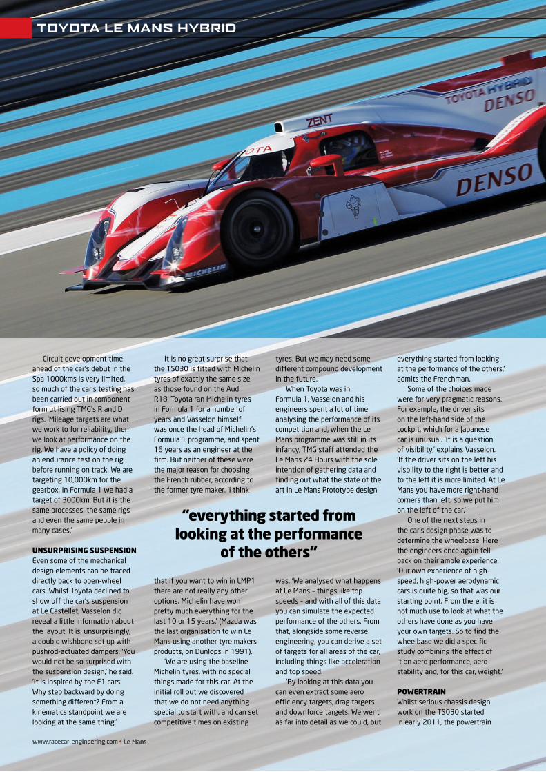
TOYOTA LE MANS HYBRID
Hybrid heavenToyota returns to Le Mans, drawing on years of hybrid development and extensive Formula 1 experience to build an innovative hybrid Le Mans Prototype
www.racecar-engineering.com • Le Mans
By SAM COLLINS
“The only big difference between Formula 1 and Le Mans is the mileage target”
REV22N3_Toyota LMP-MPAC.indd 8 21/05/2012 08:53
T oyota was one of only two teams in Formula 1 (the other being Ferrari) that built its own car in its entirety, from chassis to engine to gearbox. It was a philosophy the team had from the start and, to achieve its goal, built a vast 33km2
factory in Cologne, Germany in which to do it. But when the manufacturer pulled out of grand prix racing at the end of 2009, the facility was left somewhat redundant. Packed full of cutting-edge R and D facilities, Toyota Motorsport GmbH (TMG) could not stay dormant for long and many of the F1 engineering staff stayed on awaiting the next challenge. Soon, other F1 teams were taking advantage of the capabilities on offer, but there was still the desire amongst TMG staff to go racing again.
Then, in October 2011, it was announced that TMG was developing an all new Sports Prototype, and the philosophy of creating the entire project in house would be carried over. The result is the highly innovative new Toyota TS030 LMP1. As an example of just how integrated the project is, 86 per cent of the composites work has been done in house, a far higher amount than on similar cars such as the Audi R18 (composites by Dallara) and the now-retired Peugeot 908 (composites by Capricorn).
FORMULA 1 INFLUENCEThe Formula 1 infl uence in the TS030’s lineage is clear when its design is studied in detail. Many features found on Toyota’s TF109 and never-raced TF110 grand prix cars can also be found on the new Sports Prototype, from exhaust exits clearly based on those used on the 2009 F1 car to a steering wheel taken directly from the following year’s model.
The design and development programme also owes much to the knowledge built up by TMG in its previous incarnation as the Panasonic Toyota Racing Formula 1 team. ‘Really, for us, the only big difference between Formula 1 and Le Mans is the mileage target,’ explains Pascal Vasselon, the project’s technical director. ‘Most of the processes that we put in place for Formula 1 are being used for this project. For example, the aero development process. Whilst the regulations are different on what you can do, the process itself is a direct copy and paste from Formula 1. We start with CFD, then correlate that with scale tunnel testing, then we start to correlate with the full-scale car later on.’
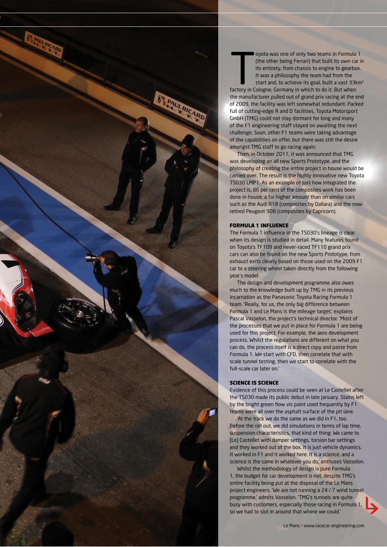
SCIENCE IS SCIENCEEvidence of this process could be seen at Le Castellet after the TS030 made its public debut in late January. Stains left by the bright green fl ow vis paint used frequently by F1 teams were all over the asphalt surface of the pit lane.
‘At the track we do the same as we did in F1, too. Before the roll out, we did simulations in terms of lap time, suspension characteristics, that kind of thing. We came to [Le] Castellet with damper settings, torsion bar settings and they worked out of the box. It is just vehicle dynamics. It worked in F1 and it worked here. It is a science, and a science is the same in whatever you do,’ enthuses Vasselon.
Whilst the methodology of design is pure Formula 1, the budget for car development is not, despite TMG’s entire facility being put at the disposal of the Le Mans project engineers. ‘We are not running a 24 / 7 wind tunnel programme,’ admits Vasselon. ‘TMG’s tunnels are quite busy with customers, especially those racing in Formula 1, so we had to slot in around that where we could.’
Le Mans • www.racecar-engineering.com
TOYOTA LE MANS HYBRID
REV22N3_Toyota LMP-MPAC.indd 9 21/05/2012 08:54
www.racecar-engineering.com • Le Manswww.racecar-engineering.com • Le Mans
TOYOTA LE MANS HYBRID
Circuit development time ahead of the car’s debut in the Spa 1000kms is very limited, so much of the car’s testing has been carried out in component form utilising TMG’s R and D rigs. ‘Mileage targets are what we work to for reliability, then we look at performance on the rig. We have a policy of doing an endurance test on the rig before running on track. We are targeting 10,000km for the gearbox. In Formula 1 we had a target of 3000km. But it is the same processes, the same rigs and even the same people in many cases.’
UNSURPRISING SUSPENSIONEven some of the mechanical design elements can be traced directly back to open-wheel cars. Whilst Toyota declined to show off the car’s suspension at Le Castellet, Vasselon did reveal a little information about the layout. It is, unsurprisingly, a double wishbone set up with pushrod-actuated dampers. ‘You would not be so surprised with the suspension design,’ he said. ‘It is inspired by the F1 cars. Why step backward by doing something different? From a kinematics standpoint we are looking at the same thing.’
It is no great surprise that the TS030 is fi tted with Michelin tyres of exactly the same size as those found on the Audi R18. Toyota ran Michelin tyres in Formula 1 for a number of years and Vasselon himself was once the head of Michelin’s Formula 1 programme, and spent 16 years as an engineer at the fi rm. But neither of these were the major reason for choosing the French rubber, according to the former tyre maker. ‘I think
that if you want to win in LMP1 there are not really any other options. Michelin have won pretty much everything for the last 10 or 15 years.’ (Mazda was the last organisation to win Le Mans using another tyre makers products, on Dunlops in 1991).
‘We are using the baseline Michelin tyres, with no special things made for this car. At the initial roll out we discovered that we do not need anything special to start with, and can set competitive times on existing
tyres. But we may need some different compound development in the future.’
When Toyota was in Formula 1, Vasselon and his engineers spent a lot of time analysing the performance of its competition and, when the Le Mans programme was still in its infancy, TMG staff attended the Le Mans 24 Hours with the sole intention of gathering data and fi nding out what the state of the art in Le Mans Prototype design
was. ‘We analysed what happens at Le Mans – things like top speeds – and with all of this data you can simulate the expected performance of the others. From that, alongside some reverse engineering, you can derive a set of targets for all areas of the car, including things like acceleration and top speed.
‘By looking at this data you can even extract some aero effi ciency targets, drag targets and downforce targets. We went as far into detail as we could, but
everything started from looking at the performance of the others,’ admits the Frenchman.
Some of the choices made were for very pragmatic reasons. For example, the driver sits on the left-hand side of the cockpit, which for a Japanese car is unusual. ‘It is a question of visibility,’ explains Vasselon. ‘If the driver sits on the left his visbility to the right is better and to the left it is more limited. At Le Mans you have more right-hand corners than left, so we put him on the left of the car.’
One of the next steps in the car’s design phase was to determine the wheelbase. Here the engineers once again fell back on their ample experience. ‘Our own experience of high-speed, high-power aerodynamic cars is quite big, so that was our starting point. From there, it is not much use to look at what the others have done as you have your own targets. So to fi nd the wheelbase we did a specifi c study combining the effect of it on aero performance, aero stability and, for this car, weight.’
POWERTRAIN Whilst serious chassis design work on the TS030 started in early 2011, the powertrain
“everything started fromlooking at the performance
of the others”
REV22N3_Toyota LMP-MPAC.indd 10 21/05/2012 08:54
Le Mans • www.racecar-engineering.com
TOYOTA LE MANS HYBRID
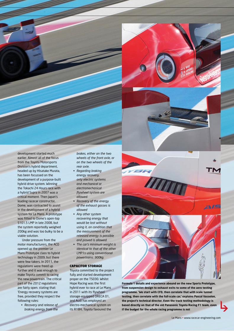
Formula 1 details and experience abound on the new Sports Prototype,
from suspension design to exhaust exits to some of the aero testing
programme. ‘We start with CFD, then correlate that with scale tunnel
testing, then correlate with the full-scale car,’ explains Pascal Vasselon,
the project’s technical director. Even the track testing methodology is
based directly on that of the old Panasonic Toyota Racing F1 team, even
if the budget for the whole racing programme is not
development started much earlier. Almost all of the focus from the Toyota Motorsports Division’s hybrid department, headed up by Hisatake Murata, has been focussed on the development of a purpose-built hybrid drive system. Winning the Tokachi 24 Hours race with a hybrid Supra in 2007 was a critical moment. Then Japan’s leading racecar constructor, Dome, was contracted to assist in the development of a hybrid system for Le Mans. A prototype was fi tted to Dome’s open-top S101.5 LMP in late 2008, but the system reportedly weighed 200kg and was too bulky to be a viable solution.
Under pressure from the motor manufacturers, the ACO opened up the premier Le Mans Prototype class to hybrid technology in 2009, but there were few takers. In 2011, the regulations were freed up further and it was enough to make Toyota commit to racing the new powertrain. The critical part of the 2012 regulations are fairly open. stating that: ‘Energy recovery systems are free, provided they respect the following rules:
• Recovery and release of braking energy from the
brakes, either on the two wheels of the front axle, or on the two wheels of the rear axle.
• Regarding braking energy recovery, only electric systems and mechanical or electromechanical fl ywheel system are allowed.
• Recovery of the energy of the exhaust gasses is allowed
• Any other system recovering energy that would be lost without using it, on condition that the measurement of the released energy is possible and proved is allowed.
• The car’s minimum weight is identical to that of the other LMP1s using conventional powertrains: 900kg.
CAPACITOR STORAGEToyota committed to the project fully and started development proper on the TS030. Whilst Hope Racing was the fi rst hybrid ever to race at Le Mans in 2011 with its fl ywheel storage-equipped ORECA 01, and Audi has employed an electro-mechanical system on its R18H, Toyota favoured the
REV22N3_Toyota LMP-MPAC.indd 11 21/05/2012 08:54
www.racecar-engineering.com • Le Manswww.racecar-engineering.com • Le Mans
electronic route. ‘Flywheels were not really an option for us,’ explains Vasselon. ‘We studied both batteries and capacitors and, at the moment, the best compromise was capacitors.It is a combination of the weight and regulations.’
The last major motorsport programme to develop a capacitor-based storage solution was BMW Sauber with its KERS-equipped F1.09. That car was not a success, but technology has moved on since then.
‘Capacitors have high power but low volume compared to a lithium battery, which has big storage but no power,’ explains Murata. ‘We evaluated both systems [and decided] capacitor is better than lithium battery for our usage. We found that the lithium battery has a big resistance, which causes heat. With this new type of capacitor it is much better and we are already working on better cooling and packaging solutions.’
Weight was a major factor in the decision to use the new capacitors made by team partner, Nisshinbo. The system tested in the Dome was too heavy and, despite the weight coming down substantially, Toyota admits openly that it is still an issue.
‘Our hybrid system is huge and heavy,’ admits a surprisingly candid Murata. ‘We have to keep to the minimum weight of 900kg.
Usually without the hybrid system, the car is around 750kg-800kg. The heaviest sub-system on the car is the hybrid, but we also carry ballast.’
Installing the system on the car without compromising the vehicle dynamics was a major challenge for the chassis team at
TMG, but a simple solution was arrived at: ‘We have [a] passenger in the car! These cars are fortunately two seaters so, on the left is the driver, on the right is the capacitor box,’ explains Vasselon, hinting that the two may weigh roughly the same.
‘Le Mans Sportscars are idealto develop the hybrid systemsas you have the space to put itin the car.’
One area of the system that Toyota has yet to fi nalise could create a major difference to the car’s dynamics. The new regulations stipulate that the
hybrid system can be front mounted, effectively making the car four-wheel drive. However, if the system acts on the front wheels it cannot activate below 120kph, whilst at the rear it can run at any speed.
Both a two-wheel drive
TOYOTA LE MANS HYBRID
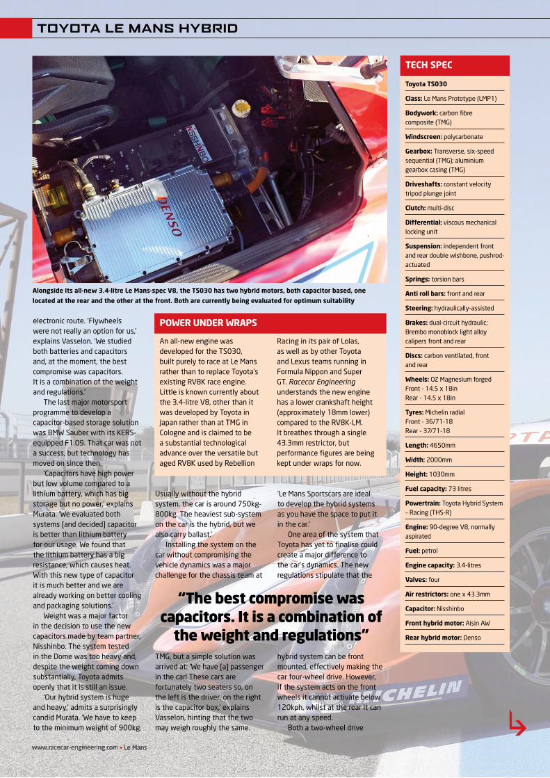
Toyota TS030
Class: Le Mans Prototype (LMP1)
Bodywork: carbon fi brecomposite (TMG)
Windscreen: polycarbonate
Gearbox: Transverse, six-speed sequential (TMG); aluminium gearbox casing (TMG)
Driveshafts: constant velocity tripod plunge joint
Clutch: multi-disc
Differential: viscous mechanical locking unit
Suspension: independent front and rear double wishbone, pushrod-actuated
Springs: torsion bars
Anti roll bars: front and rear
Steering: hydraulically-assisted
Brakes: dual-circuit hydraulic; Brembo monoblock light alloy calipers front and rear
Discs: carbon ventilated, front and rear
Wheels: OZ Magnesium forgedFront - 14.5 x 18inRear - 14.5 x 18in
Tyres: Michelin radialFront - 36/71-18Rear - 37/71-18
Length: 4650mm
Width: 2000mm
Height: 1030mm
Fuel capacity: 73 litres
Powertrain: Toyota Hybrid System – Racing (THS-R)
Engine: 90-degree V8, normally aspirated
Fuel: petrol
Engine capacity: 3.4-litres
Valves: four
Air restrictors: one x 43.3mm
Capacitor: Nisshinbo
Front hybrid motor: Aisin AW
Rear hybrid motor: Denso
TECH SPEC
An all-new engine was developed for the TS030, built purely to race at Le Mans rather than to replace Toyota’s existing RV8K race engine. Little is known currently about the 3.4-litre V8, other than it was developed by Toyota in Japan rather than at TMG in Cologne and is claimed to be a substantial technological advance over the versatile but aged RV8K used by Rebellion
Racing in its pair of Lolas, as well as by other Toyota and Lexus teams running in Formula Nippon and Super GT. Racecar Engineering understands the new engine has a lower crankshaft height (approximately 18mm lower) compared to the RV8K-LM.It breathes through a single 43.3mm restrictor, but performance fi gures are being kept under wraps for now.
POWER UNDER WRAPS
Alongside its all-new 3.4-litre Le Mans-spec V8, the TS030 has two hybrid motors, both capacitor based, one
located at the rear and the other at the front. Both are currently being evaluated for optimum suitability
“The best compromise was capacitors. It is a combination of
the weight and regulations”
REV22N3_Toyota LMP-MPAC.indd 12 21/05/2012 08:55

AS11_35_AutosportBearings:Layout 1 7/12/10 14:54 Page 1
THE MOTORSPORT SPECIALISTS
the result you need . . .where you need it . . .
on the track
AUTOSPORT BEARINGS & COMPONENTS
From initial concept through design & development, prototype to fi nal production,we are there to assist every step of the way
www.autosport-bearings.co.uk
Bearings, Fasteners, Adhesives, Oils, Lubricants and much more.
Unit 3, Shepperton Business Park, Govett Avenue, Shepperton, Middx TW17 8BATel: +44 (0)1932 225777 • Fax: +44 (0)1932 222215Email: [email protected]
Full live coverage at www.radiolemans.com
56 startmillions follow
Radio Le Mans Ad.indd 1 31/05/2012 11:37
As used at the 2012 Le Mans 24Hrs
TOYOTA LE MANS HYBRID
system and a four-wheel drive system have been developed for the TS030 and both have the capacitor storage in the passenger compartment. The rear-wheel system is mounted on the transmission casing and has been developed by Toyota group company, Denso, whilst the front motor, which seems to be the more experimental option, has been developed by Aisin AW. Both systems are being evaluated on the car and there is a complex web of trade offs as both have advantages and disadvantages.
‘Of course there is a direct correlation between the front motor and the aero balance target,’ Vasselon points out. The front motor requires cooling and driveshafts influence the airflow on this critical part of the car. ‘We are still investigating. It’s a balance between pure performance and weight. We are not going to run at the same weight with the two systems, and it is part of the performance too, as with one of the systems you can either run over weight or with less ballast,’ he continues.
The TS030 chassis has clearly been designed to be able to accommodate the four-wheel drive system and the wheelbase and overall weight distribution has taken that into account. ‘When we use the rear system we have to put ballast in the front. The ACO does not limit the weight of the hybrid system, but it is difficult to keep to the 900kg, and the ballast is actually very small,’ explains Murata.
Toyota is not totally happy with the regulations as they stand. In early drafts the technical regulations permitted energy storage of 1MJ but, in the final regulations issued late in 2011, that figure was halved, largely thanks to Peugeot lobbying.
energy release‘The final details came late, but the framework of the rules was done a long time ago. We could prepare the car to go in that direction but it did not go exactly where we were expecting it to go,’ explains Vasselon, with an air of reluctant acceptance. ‘We were in favour of much bigger energy
release between corners, and we are a little bit disappointed that we only have 0.5MJ of storage, but we understand and accept the ACO decision. We wanted 1MJ, bigger energy release, bigger impact of the hybrid system on performance and, with our system, we are able to cover a range of energy releases.’
The system has three driver-controlled modes, adjusted by a rotary switch on the steering wheel. Mode A sets up the hybrid system (and one assumes the engine map) for maximum performance, giving the TS030 the ability to easily drop below 3m30 around the circuit at Le Mans, whilst mode C is set for maximum fuel saving, allowing the car to run longer stints. Mode B is a halfway house between both. It is likely that there are other mapping adjustments that can be made to get the best traction from the systems also.
Despite being so new, the Toyota (and ORECA) engineers are already getting used to running the hybrid on track and Vasselon feels assured that the
monocoque itself has longevity, even though it is possible that next year another all-new car will roll out of Cologne. ‘We could do several seasons with the same monocoque,’ he says. ‘We improved our correlation in terms of mileage testing with the TF109 during the Pirelli tyre testing programme. We found out it was possible to do very long mileage with our monocoques, so it is still to be decided if we do a new design for next year or continue with this one.’
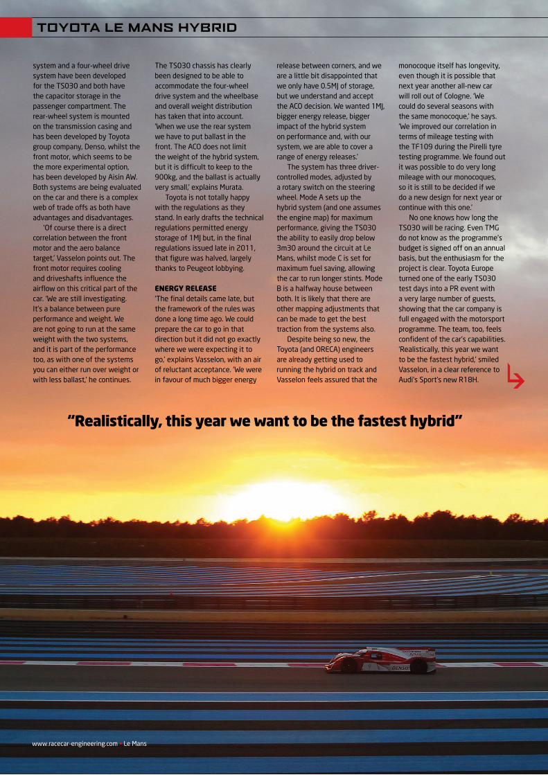
No one knows how long the TS030 will be racing. Even TMG do not know as the programme’s budget is signed off on an annual basis, but the enthusiasm for the project is clear. Toyota Europe turned one of the early TS030 test days into a PR event with a very large number of guests, showing that the car company is full engaged with the motorsport programme. The team, too, feels confident of the car’s capabilities. ‘Realistically, this year we want to be the fastest hybrid,’ smiled Vasselon, in a clear reference to Audi’s Sport’s new R18H.
“realistically, this year we want to be the fastest hybrid”
www.racecar-engineering.com • Le Mans
REV22N3_Toyota LMP-MPAC.indd 14 21/05/2012 08:55
www.racecar-engineering.com • Le Mans
‘It was cool to drive the car for the first time. Just leaving the garage on the
electric power is very futuristic, then when you let the clutch go and the internal combustion engine kicks in it is like an old friend has returned! When we put on the slick tyres I could feel that the car generates a very good amount of grip, so I think we have a good base and I think we can turn this into a really fast car. I am definitely very happy,
but my nature is to also be analytical so I know there is still a lot of work to be done.
‘Compared to the Peugeot
908, it feels different for many reasons. First of all you are sitting on the left-hand side of the car, not the right, which is a big difference.
‘In the driver seat for the knees and leg positioning, it is quite good – 10mm more than the Peugeot at least – but in
terms of space at the top, elbow, shoulder and head space it is much more squashed. I was scared of it at first but, once I had driven the car a bit, I was
okay, but there is less space than there is in a Formula 1 car, so you can tell how tight it is.
‘When you are operating on the limit, the delivery of torque and power of the diesel at low revs with a turbo is very different to a normally aspirated engine. You drive with power over a bigger band, so not so much torque but a different power shape. With high performance cars you can steer not only with the steering wheel but also with the throttle, so if your power output is very different, it influences your driving style. When you change the driving style, you change the tyres so, like everything in racing, it is a chain of small adjustments, but for a driver it is a big thing.
‘Under acceleration you really feel the hybrid system. It is a lot of little horses pushing when you want the power, which is very good. We are still optimising the system and it has caused a few problems with traction, but now the systems are communicating better and we can already see the improvements coming.’
Alex Wurz
TOYOTA LE MANS HYBRID
DRIVING THE TS030
“power output is very different, it influences your driving style”
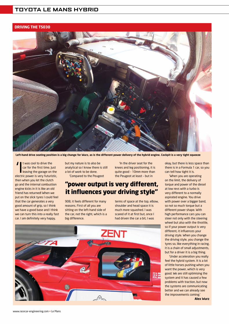
Left-hand drive seating position is a big change for Wurz, as is the different power delivery of the hybrid engine. Cockpit is a very tight squeeze
REV22N3_Toyota LMP-MPAC.indd 16 21/05/2012 08:55
www.racecar-engineering.com • June 201110
ENGINEERING SOLUTIONS
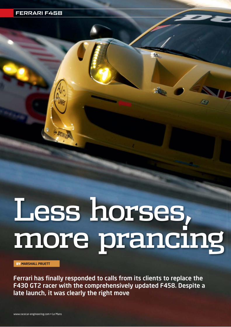
Ferrari has fi nally responded to calls from its clients to replace the F430 GT2 racer with the comprehensively updated F458. Despite a late launch, it was clearly the right move
BY MARSHALL PRUETT
www.racecar-engineering.com • Le Mans
Less horses, more prancing
FERRARI F458
REV21N6_Ferrari-MPAC.indd 10 21/05/2012 08:59
June 2011 • www.racecar-engineering.com 1111Le Mans • www.racecar-engineering.com
Less horses, more prancing W
ith two class wins at Le Mans and numerous championships in Europeand North America, Ferrari’s F430 racer took the fi ght
for supremacy in the hotly contested GT2 category to its nemisis, Porsche.
Except for the brief period during the 1990s when Ferrari’s F40 GT-LM was considered a worthy contender on the GT racing scene, Porsche’s various production-based racecars owned the lower tiers of GT competition, until the F430 moved to the forefront in 2008 and 2009.
That brief taste of glory was parried back by Weissach in 2010, with 997 RSRs winning their class at Le Mans, while championships in the ALMS and LMS drove the fi nal nails
into the F430’s coffi n.Ferrari had its nose bloodied, and had
to respond with something special. Luigi Dindo, Michelotto’s chief engineer for the F458 GTC programme, says that with the F430 at the end of its development cycle, sweeping changes were saved for the new-for-2011 F458. Rather than carry over proven elements of the F430, every section of the F458 was treated with a brand new approach.
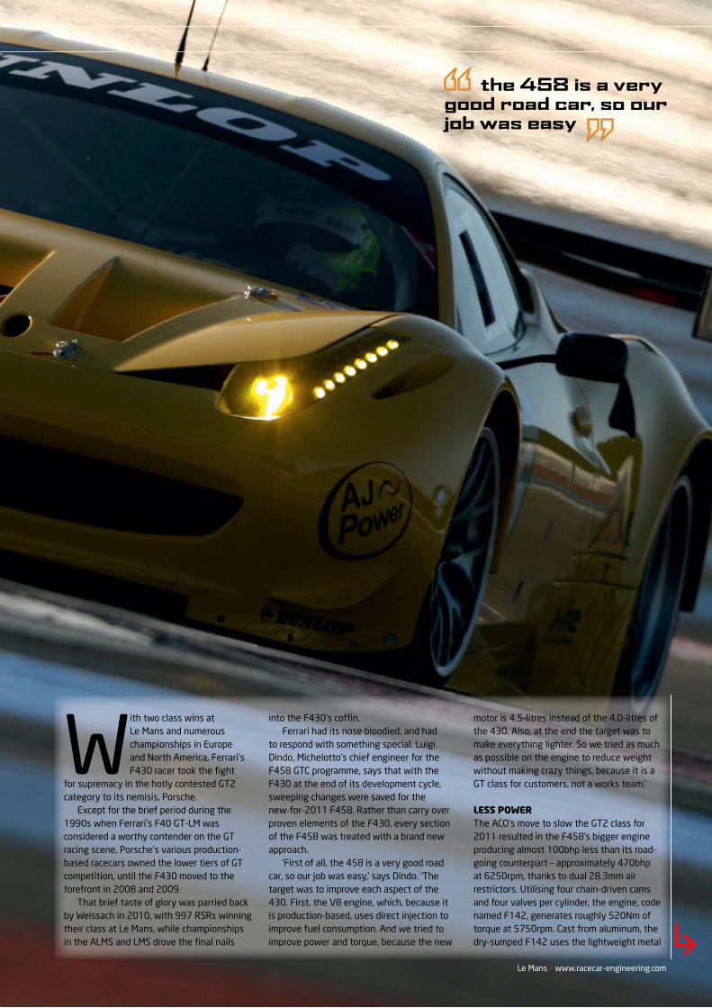
‘First of all, the 458 is a very good road car, so our job was easy,’ says Dindo. ‘The target was to improve each aspect of the 430. First, the V8 engine, which, because it is production-based, uses direct injection to improve fuel consumption. And we tried to improve power and torque, because the new
motor is 4.5-litres instead of the 4.0-litres of the 430. Also, at the end the target was to make everything lighter. So we tried as much as possible on the engine to reduce weight without making crazy things, because it is a GT class for customers, not a works team.’
LESS POWERThe ACO’s move to slow the GT2 class for 2011 resulted in the F458’s bigger engine producing almost 100bhp less than its road-going counterpart – approximately 470bhp at 6250rpm, thanks to dual 28.3mm air restrictors. Utilising four chain-driven cams and four valves per cylinder, the engine, code named F142, generates roughly 520Nm of torque at 5750rpm. Cast from aluminum, the dry-sumped F142 uses the lightweight metal
the 458 is a verygood road car, so ourjob was easy
FERRARI F458
REV21N6_Ferrari-MPAC.indd 11 21/05/2012 08:59
www.racecar-engineering.com • June 2011
FERRARI F458
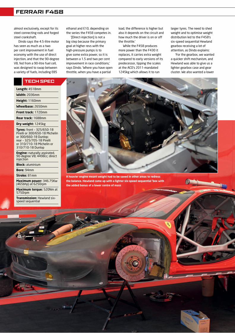
A heavier engine meant weight had to be saved in other areas to redress
the balance. Hewland came up with a lighter six-speed sequential ’box with
the added bonus of a lower centre of mass
almost exclusively, except for its steel connecting rods and forged steel crankshaft.
Dindo says the 4.5-litre motor has seen as much as a two per cent improvement in fuel economy with the use of direct injection, and that the 90-degree V8, fed from a 90-litre fuel cell, was designed to swap between a variety of fuels, including E85
ethanol and E10, depending on the series the F458 competes in.
‘[Direct-injection] is not a big step because the primary goal at higher revs with the high-pressure pumps is to give some extra power, so it is between a 1.5 and two per cent improvement in race conditions,’ says Dindo. ‘Where you have open throttle, when you have a partial
load, the difference is higher but also it depends on the circuit and how much the driver is on or off the throttle.’
While the F458 produces more power than the F430 it replaces, it carries extra weight compared to early versions of its predecessor, tipping the scales at the ACO’s 2011-mandated 1245kg which allows it to run
larger tyres. The need to shed weight and to optimise weight distribution led to the F458’s six-speed sequential Hewland gearbox receiving a lot of attention, as Dindo explains:
‘For the gearbox, we wanted a quicker shift mechanism, and Hewland was able to give us a lighter gearbox case and gear cluster. We also wanted a lower
tEch spEc
Length: 4518mm
Width: 2036mm
Height: 1160mm
Wheelbase: 2650mm
Front track: 1720mm
Rear track: 1688mm
Dry weight: 1245kg
Tyres: front – 325/650-18 Pirelli or 300/650-18 Michelin or 300/660-18 Dunlop; rear – 325/705-18 Pirelli or 310/710-18 Michelin or 310/710-18 Dunlop
Engine: naturally aspirated, 90-degree V8; 4498cc; direct injection
Block: aluminium
Bore: 94mm
Stroke: 81mm
Maximum power: 346.75Kw (465bhp) at 6250rpm
Maximum torque: 520Nm at 5750rpm
Transmission: Hewland six- speed sequential
REV21N6_Ferrari-MPAC.indd 12 21/05/2012 08:59
FERRARI F458
Le Mans • www.racecar-engineering.com
center of mass on the gearbox, and we have been able to get it. It was also made stronger because of the increased torque of the engine.’
Looks famiLiarThe F458 looks similar in some ways to the F430 but, barring the cabin’s interior, the majority of the chassis, major systems
and placement of the ancillaries have been re-worked. It would be a stretch to call the mid-engined two seater a completely new design, but the majority of the underpinnings and the body panels are different enough to stand out in a direct comparison.
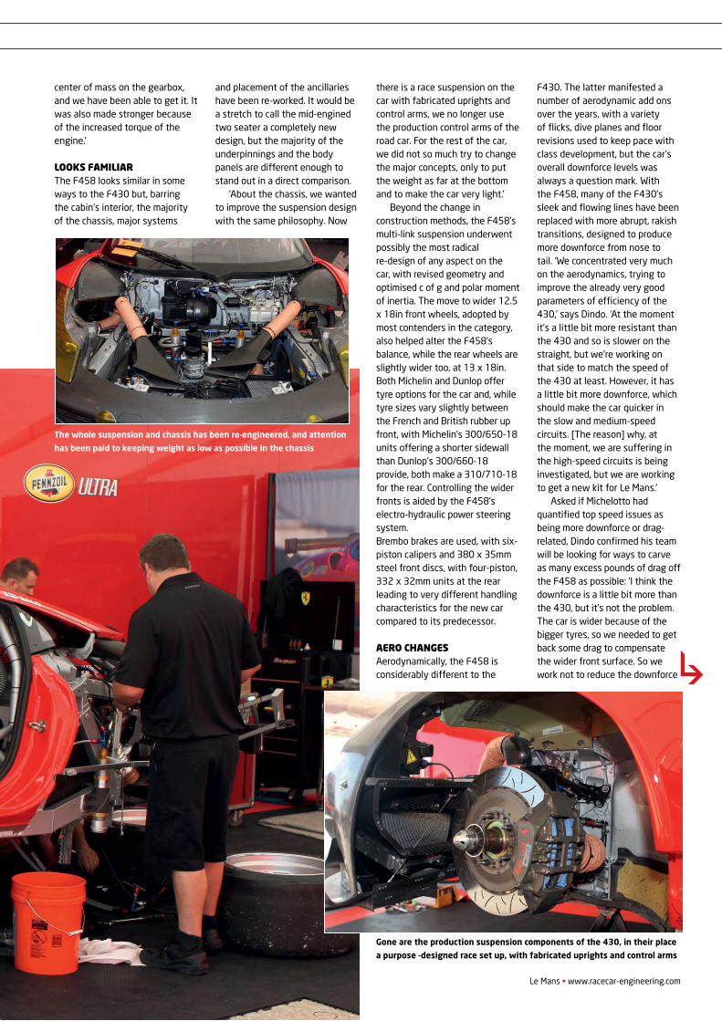
‘About the chassis, we wanted to improve the suspension design with the same philosophy. Now
there is a race suspension on the car with fabricated uprights and control arms, we no longer use the production control arms of the road car. For the rest of the car, we did not so much try to change the major concepts, only to put the weight as far at the bottom and to make the car very light.’
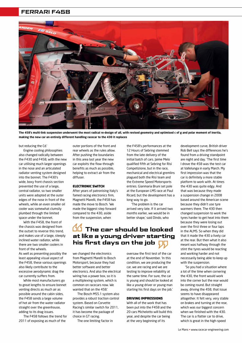
Beyond the change in construction methods, the F458’s multi-link suspension underwent possibly the most radical re-design of any aspect on the car, with revised geometry and optimised c of g and polar moment of inertia. The move to wider 12.5 x 18in front wheels, adopted by most contenders in the category, also helped alter the F458’s balance, while the rear wheels are slightly wider too, at 13 x 18in. Both Michelin and Dunlop offer tyre options for the car and, while tyre sizes vary slightly between the French and British rubber up front, with Michelin’s 300/650-18 units offering a shorter sidewall than Dunlop’s 300/660-18 provide, both make a 310/710-18 for the rear. Controlling the wider fronts is aided by the F458’s electro-hydraulic power steering system.Brembo brakes are used, with six-piston calipers and 380 x 35mm steel front discs, with four-piston, 332 x 32mm units at the rear leading to very different handling characteristics for the new car compared to its predecessor.
aero changesAerodynamically, the F458 is considerably different to the
F430. The latter manifested a number of aerodynamic add ons over the years, with a variety of flicks, dive planes and floor revisions used to keep pace with class development, but the car’s overall downforce levels was always a question mark. With the F458, many of the F430’s sleek and flowing lines have been replaced with more abrupt, rakish transitions, designed to produce more downforce from nose to tail. ‘We concentrated very much on the aerodynamics, trying to improve the already very good parameters of efficiency of the 430,’ says Dindo. ‘At the moment it’s a little bit more resistant than the 430 and so is slower on the straight, but we’re working on that side to match the speed of the 430 at least. However, it has a little bit more downforce, which should make the car quicker in the slow and medium-speed circuits. [The reason] why, at the moment, we are suffering in the high-speed circuits is being investigated, but we are working to get a new kit for Le Mans.’
Asked if Michelotto had quantified top speed issues as being more downforce or drag-related, Dindo confirmed his team will be looking for ways to carve as many excess pounds of drag off the F458 as possible: ‘I think the downforce is a little bit more than the 430, but it’s not the problem. The car is wider because of the bigger tyres, so we needed to get back some drag to compensate the wider front surface. So we work not to reduce the downforce
The whole suspension and chassis has been re-engineered, and attention
has been paid to keeping weight as low as possible in the chassis
Gone are the production suspension components of the 430, in their place
a purpose -designed race set up, with fabricated uprights and control arms
REV21N6_Ferrari-MPAC.indd 13 21/05/2012 08:59
FERRARI F458
Le Mans • www.racecar-engineering.com
but reducing the Cd.’Engine cooling philosophies
also changed radically between the F430 and F458, with the new car utilising much larger openings in the nose and an articulated radiator venting system designed into the bonnet. The F430’s wide, boxy front chassis section prevented the use of a large, central radiator, so two smaller units were adopted at the outer edges of the nose in front of the wheels, while an even smaller oil cooler was somewhat clumsily plumbed through the limited space under the bonnet.
With the F458, the front of the chassis was designed from the outset to reverse this trend, and makes use of a large, steeply inclined water radiator, while there are two smaller coolers in front of the wheels. As well as presenting possibly the least appealing visual aspect of the F458, these various openings also likely contribute to the excessive aerodynamic drag the car currently suffers from.
While most manufacturers go to great lengths to ensure bonnet venting directs as much air as possible around the cabin sides, the F458 sends a large volume of hot air from the water radiator straight over the greenhouse, adding to its drag issues.
The F458 follows the trend for 2011 of exposing as much of the
outer portions of the front and rear wheels as the rules allow. After pushing the boundaries in this area last year the new car exploits the flow-through benefits as much as possible, helping to extract air from the diffuser.
ElEctronic switchAfter years of patronising Italy’s famed racing electronics firm, Magnetti Marelli, the F458 has made the move to Bosch. ‘We made the biggest step forward compared to the 430, aside from the suspension, when
we changed the electronics from Magnetti Marelli to Bosch Motorsport, because they had better software and better electronics. And also the electrical wiring has a power box, so it is a multiplexing system, which is common on racecars now. We wanted that on the 458.’
The Bosch MS5.1 system also provides a robust traction control system. Based on Corvette Racing’s similar switch for 2011, it has become the package of choice in GT racing.
The one limiting factor in
the F458’s performances at the 12 Hours of Sebring stemmed from the late delivery of the initial batch of cars. Jaime Melo qualified fifth at Sebring for Risi Competizione, but in the race, mechanical and electrical gremlins plagued both the Risi team and the Extreme Speed Motorsports entries. Gianmaria Bruni set pole at the European LMS race at Paul Ricard, but the development has a long way to go.
‘The problem is the car arrived very late. If it arrived two months earlier, we would be in better shape,’ said Dindo, who
oversaw the first test of the car at the end of November. ‘In this condition, we are producing the car, we are racing and we are testing to improve reliability at the same time. For sure, the car is young and should be looked at like a young driver or young man starting his first days on the job.’
Driving imprEssionsWith all of the work that has been put into the F458 and the 20 cars Michelotto will build this year, and despite the car being at the very beginning of its
development curve, British driver Rob Bell says the differences he’s found from a driving standpoint are night and day. ‘The first time I drove the 458 was the test car at Vallelunga in early March. My first impression was that the car is definitely a more stable platform to work with. At times the 430 was quite edgy. And that was because they made a suspension change in 2008 based around the American scene because they didn’t use tyre warmers there. The 430 then changed suspension to work the tyres harder to get heat into them because they were losing out over the first three or four laps in the ALMS. So when they did that it made the 430 a lively car at the rear. But then what it also meant was halfway through the stint the tyres would be reacting and working harder and not necessarily being able to keep up with the suspension.
‘So you had a situation where a lot of the time when cornering the 430, the front would work into the corner but the rear would be coming round. But straight away, driving the 458, that issue seems to have disappeared altogether. It felt very, very stable on brakes and turning at the rear, which was our biggest concern when we finished with the 430. The car is a flatter car to drive, which is great in the high-speed
The 458’s multi-link suspension underwent the most radical re-design of all, with revised geometry and optimised c of g and polar moment of inertia,
making the new car an entirely different handling racecar to the 430 it replaces
The car should be looked at like a young driver starting his first days on the job
REV21N6_Ferrari-MPAC.indd 15 21/05/2012 09:00
www.racecar-engineering.com • Le Mans
FERRARI F458
stuff, really nice. The 458 is a case of, “wow, you can really attack the corner now and get turned in and be aggressive and not worry about the rear losing grip”. It’s a big step forward, for sure.’
Comparing the cornering attributes of the F430s and F458s at the 12 Hours of Sebring revealed how much Michelotto has accomplished by altering the ride quality of the new car. Where the F430s always used a bit of extra roll and dive to load the tyres and transfer weight, the F458 moves visibly less while cornering and under hard braking. Simply put, the normally demonstrative moves of the Prancing Horse have been muted.
After listening in to a number of conversations in the pit lane amongst F458 drivers, perhaps too much anti-dive geometry has been used, leading to the rather numb handling sensation some drivers reported, so it is believed the first batch of updates for the F458 will include geometry revisions to mitigate this.
Bell, who took the F458’s first major international win at the Paul Ricard in April, says his JMW team worked through a number of changes at the French circuit to try and improve the car’s straight-line limitations. ‘First, we’ve all got a new, taller Gurney on the rear now, and it’s quite obvious when you get up to a certain speed that it’s doing its job. It’s been put there to slow us down, and it does. You definitely feel like you get into top gear and not a lot really happens. So I would say that’s been true with most of the cars. Having said that, in the past with the Ferrari, when you’ve taken aero out of it, it’s responded very well. But I think the truth will be known at Le Mans, when we start taking aero off. We took a little bit off at Paul Ricard and played with bits and bobs, and didn’t really find a huge amount, to be honest. It’s little stuff we’re looking to improve, and Michelotto will get it sorted quickly, like they always do.’
Bell also reported that the change to the Bosch MS5.1
After racing Extreme Speed’s F458 at Sebring
on Michelins and winning Paul Ricard in JMW’s Dunlop-shod F458, British driver Rob Bell says the advanced state of tyre technology from both companies give Ferrari racers an excellent choice.
’Michelin has been there for years. They are the benchmark that everyone aims for, but I’ve done a lot of work with Dunlop over the last five or six years and I think they’re knocking on the door. They’ve won the first two major races of the year [Sebring and Paul Ricard], so they’ve done their sums. They’re both good companies, though, and their products both work very well on the car. The only thing I would say is, I suppose Michelin have about six months on the car ahead of Dunlop.
And there’s a slight difference in balance – one seems to be slightly stronger at front grip, the other is slightly stronger at rear grip. In the grand scheme of things, they’ve both done a great job.
‘When you get down to the finite, real last few per cent of tyre performance, that’s really getting down to the last one or two tenths per lap. Both seem to last very well on the car and again, only time will tell, but maybe the car is just good on its tyres. We’re still gathering data at the minute, and we don’t really know the answer, I guess because we’ve not had a really hot day, but Sebring is a pretty hard test on tyres and they lasted pretty well. Again, at Ricard, the tyre consistency was very good, so I think both have got parity at the minute.’
system has been seamless so far: ‘For a completely new system it’s been a very smooth transition. And certainly everything that we’ve had so far has worked perfectly. You’d expect electronic glitches for the first six months, but we haven’t really had any on the cars I’ve driven. And I think it’s a step forward because, for example, the traction control system is more advanced. It’s a nicer system to work with as a driver, and that can only be good – we don’t necessarily rely on traction control but, if it’s there
and you don’t feel it’s working, it’s going to be looking after the tyres better than we humanly can. I think that will be seen in long durations, as it does seem to be doing its job. The Marelli system was fine, but for example its traction control felt a bit basic.’
There’s no doubt the F458 has a long way to go to catch and surpass the F430’s record in competition but, if it’s early potential is anything to go by, it looks like Munich and Detroit might have another five years of hellish fighting ahead.
TyRE choIcE
With a choice of either Michelin or Dunlop tyres, drivers have two excellent
products on offer that, in early tests, have shown remarkable parity
Pict
ures
LAT
REV21N6_Ferrari-MPAC.indd 16 21/05/2012 09:00
www.racecar-engineering.com • Le Mans
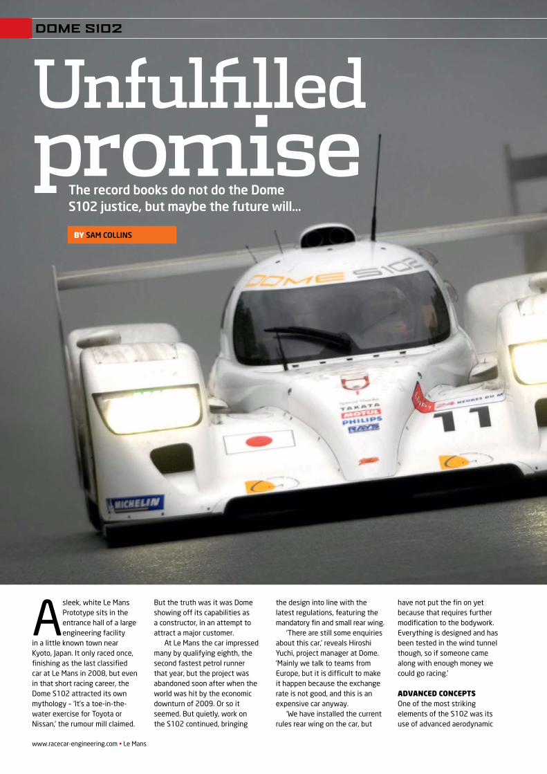
A sleek, white Le Mans Prototype sits in the entrance hall of a large engineering facility
in a little known town near Kyoto, Japan. It only raced once, finishing as the last classified car at Le Mans in 2008, but even in that short racing career, the Dome S102 attracted its own mythology – ‘It’s a toe-in-the-water exercise for Toyota or Nissan,’ the rumour mill claimed.
But the truth was it was Dome showing off its capabilities as a constructor, in an attempt to attract a major customer.
At Le Mans the car impressed many by qualifying eighth, the second fastest petrol runner that year, but the project was abandoned soon after when the world was hit by the economic downturn of 2009. Or so it seemed. But quietly, work on the S102 continued, bringing
the design into line with the latest regulations, featuring the mandatory fin and small rear wing.
‘There are still some enquiries about this car,’ reveals Hiroshi Yuchi, project manager at Dome. ‘Mainly we talk to teams from Europe, but it is difficult to make it happen because the exchange rate is not good, and this is an expensive car anyway.
‘We have installed the current rules rear wing on the car, but
have not put the fin on yet because that requires further modification to the bodywork. Everything is designed and has been tested in the wind tunnel though, so if someone came along with enough money we could go racing.’
AdvAnced conceptsOne of the most striking elements of the S102 was its use of advanced aerodynamic
The record books do not do the Dome S102 justice, but maybe the future will…
by SAM COLLINS
Unfulfilled promise
DOME S102
REV21N12_Dome-MPAC.indd 20 21/05/2012 09:02
concepts, developed in two wind tunnels over three years. Interestingly, the two tunnels were different scales. ‘It was easier to change the shape of the model quickly with the quarter-scale tunnel. We could test concepts like the separated fenders, and fi x the general shape of the car that way,’ Yuchi reveals. The quarter-scale model was also critical in making the choice between an open car and
the lower drag coupe. ‘With the 60 per cent scale model you need to use a sting attached to the top to support the model in the tunnel, and that interferes with the area you are looking at, but with the quarter-scale model we just use a wire. We found that on paper there was not much between the two concepts. Ifyou did very well with an open car you could get to within 0.5 per cent of the effi ciency of a
closed car, but at Le Mans 0.5 per cent is huge!’
The choice to build a coupe was further infl uenced by the limited range of engines available to the project. The popular 5.5-litre Judd V10 was chosen, but it was no match for the works’ diesel and petrol engines. Instead, the emphasis was placed on aerodynamic effi ciency, and there the larger wind tunnel programme came into play.
Using its well-regarded, on-site ‘Furyusha ‘tunnel, Yuchi’s team started to hone the S102’s shape at 60 per cent scale.
‘Once we had fi xed the shape we switched to the large tunnel. The small scale had allowed us to see trends, but you need a larger tunnel to do better detail. You can also be more accurate with a larger model. The repeatability of the data from the quarter-scale model could be plus or minus 0.3
Le Mans • www.racecar-engineering.com
Dome S102
Class: ACO LMP1 2008 (updated to 2011 specifi cations)
Chassis: Dome Carbon Magic composite monocoque coupe
Engine : Judd GV5, 5,496cc normally aspirated gasoline V8.
Suspension: Double wishbone front and rear with pushrod actuated dampers
Brakes: Carbon ceramic
Transmission: Xtrac 6 speed sequential gearbox
Electronics: Dome / Cosworth
Tyres: Michelin LMP1
Weight: 900kg
Dimensions: Length: 4650mmWidth: 1995mmHeight: 920mmWheelbase: 2900mm
TECH SPEC
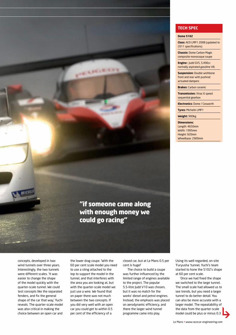
“if someone came along with enough money we could go racing”
DOME S102
REV21N12_Dome-MPAC.indd 21 21/05/2012 09:02
www.racecar-engineering.com • Le Mans
DOME S102
per cent so, if you are looking for a 0.2 per cent gain, you have to use a bigger model. At 60 per cent, it could be 0.1 per cent, so you can make those gains.’
Missed opportunityAfter the S102 and its engineers returned from Europe, they had a chance to reflect on the car’s performance and look for ways to improve. ‘When we took the car to Le Mans it was very young, just two or three months old,’ admits Yuchi. ‘We couldn’t do enough development on it in the time we had, not even enough to find a good set up. After we got back we did two more track tests, and even then we were finding better set ups all of the time. Also at Le Mans we had a traction problem, but we fixed this very quickly afterwards. So we knew that if we went back in 2009 we would have a much better mechanical set up, but it was not to be.’
The lessons learned from Le Mans in 2008 were many and, with the car still having a lot of development potential, it does not seem unreasonable to suspect that the S102 could have mixed it with the works’ diesels in 2009. ‘We have not
had an opportunity to show what the car can do,’ complains Yuchi. ‘I still have some ideas about changing the packaging. I have ideas about a whole new
car – the S103. We know we can make the monocoque much lighter, as we have made some steps there. We also did a loading test, to see how much it could take. We simply loaded that up
until it broke. Normally in a crash test you stop before the chassis breaks up but, for our knowledge, we destroyed a car. We went way beyond the maximum loads and
found our chassis was overspec’d. The tub currently weighs just below 90kg but we think we can match the 75kg of the Audi R18.’
Despite the project slowing after 2008, it has never stopped
entirely, and the car in the lobby at the Dome factory is fitted with some 2011-spec components. ‘At the front of the car we are happy. Other people have copied us, too. In 2005 we were testing concepts in the wind tunnel at quarter scale that we saw on the Audi R15, so we are confident with the front end. At the rear, however, there is much more development, getting more downforce for no more drag. We can make the rear deck much lower and look at some of the mechanical packaging of the car, like Adrian Newey with the rear of the Red Bull.’
Regulation changes since 2008 have also moved the focus to the rear of the car, notably because the big Judd V10 in the back of the S102 has been effectively outlawed, or at best rendered uncompetitive against new-rules engines.
‘On our car the engine was mounted much further forward than others, because the regulations stated that the engine and primary rollover structure should not overlap. But on a coupe there is no primary roll structure, such as the hoops on a roadster, so we discussed
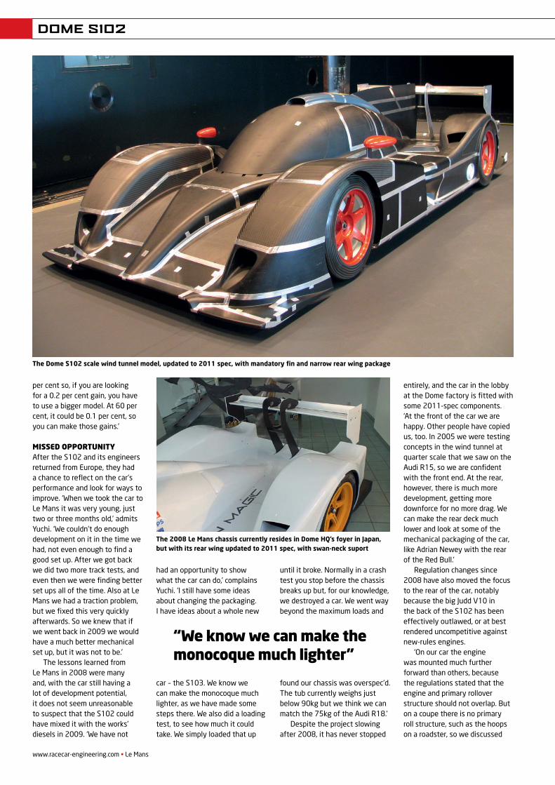
The Dome S102 scale wind tunnel model, updated to 2011 spec, with mandatory fin and narrow rear wing package
The 2008 Le Mans chassis currently resides in Dome HQ’s foyer in Japan, but with its rear wing updated to 2011 spec, with swan-neck suport
“We know we can make the monocoque much lighter”
REV21N12_Dome-MPAC.indd 22 21/05/2012 09:04
www.racecar-engineering.com • Le Mans
DOME S102
this with the ACO and they let us mount the engine with an overlap. But now we don’t need this layout with the smaller engines because that approach made the chassis slightly heavier than it could have been, [and this is] one of the ways we can save on chassis weight. Doing
that did mean we could put more weight on the front axle, and we achieved 48 per cent of the weight on the front. We had already started discussing with Michelin about using larger front tyres in 2008 because we had experience of it from our work in Super GT. Then, when the rear wing size was cut, that actually suited us, and the balance on the car would have been much better.’
Other teams independently discovered many of the developments planned by Dome for the S102, such as wider front tyres, but there are some that
Yuchi is still keeping to himself, perhaps to employ on any new Dome LMP1. Suffice to say, he is already thinking about some advanced concepts. ‘Looking at the rear of the Red Bull F1 car, there are some ideas there – like the suspension. You could even do a blown diffuser, but it would
destroy your fuel consumption. But as Le Mans is such a long lap, maybe it is something you could consider for the end of a stint. I suspect the ACO would not be too happy about it, even though it is within the rules!’
Dome continues to work on other racing projects, notably designing, building and developing the Super GT Honda GT500s. And whilst many of its other projects are confidential, we can now say with certainty that rumours of it being involved in the Toyota Le Mans project are wide of the mark.
Since 1979 Dome has been a fairly regular feature of the Le Mans 24 Hours, either under its own name or that of Toyota. Here are some of its more memorable entries
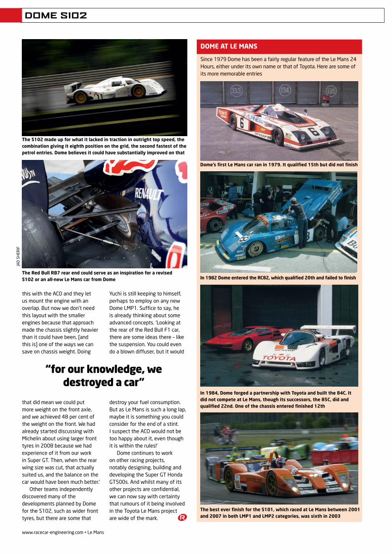
The S102 made up for what it lacked in traction in outright top speed, the combination giving it eighth position on the grid, the second fastest of the petrol entries. Dome believes it could have substantially improved on that
DOME AT LE MANS
The Red Bull RB7 rear end could serve as an inspiration for a revised S102 or an all-new Le Mans car from Dome
“for our knowledge, we destroyed a car”
Dome’s first Le Mans car ran in 1979. It qualified 15th but did not finish
In 1982 Dome entered the RC82, which qualified 20th and failed to finish
In 1984, Dome forged a partnership with Toyota and built the 84C. It did not compete at Le Mans, though its successors, the 85C, did and qualified 22nd. One of the chassis entered finished 12th
The best ever finish for the S101, which raced at Le Mans between 2001 and 2007 in both LMP1 and LMP2 categories, was sixth in 2003
JAD
SH
ERIF
REV21N12_Dome-MPAC.indd 24 21/05/2012 09:04
DELTAWING
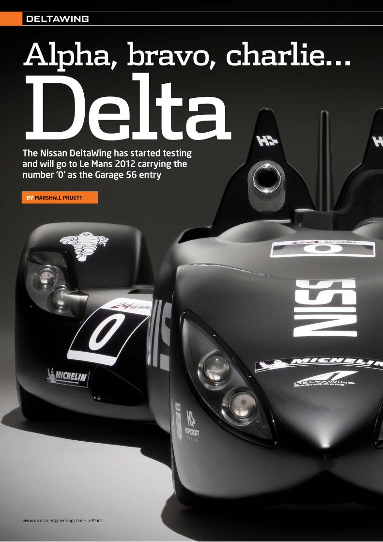
Alpha, bravo, charlie…
DeltaThe Nissan DeltaWing has started testing and will go to Le Mans 2012 carrying the number ‘0’ as the Garage 56 entry
by MarshaLL prueTT
www.racecar-engineering.com • Le Mans
REV22N5_Delta Wing-MPac.indd 8 21/05/2012 09:06
Le Mans • www.racecar-engineering.com
DELTAWING
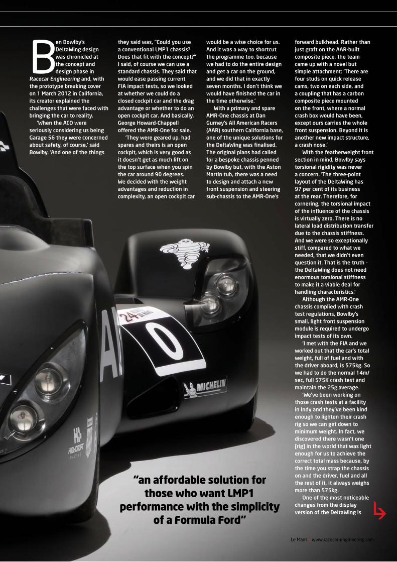
“an affordable solution for those who want LMP1
performance with the simplicity of a Formula Ford”
Ben Bowlby’s DeltaWing design was chronicled at the concept and design phase in
Racecar Engineering and, with the prototype breaking cover on 1 March 2012 in California, its creator explained the challenges that were faced with bringing the car to reality.
‘When the ACO were seriously considering us being Garage 56 they were concerned about safety, of course,’ said Bowlby. ‘And one of the things
they said was, “Could you use a conventional LMP1 chassis? Does that fit with the concept?” I said, of course we can use a standard chassis. They said that would ease passing current FIA impact tests, so we looked at whether we could do a closed cockpit car and the drag advantage or whether to do an open cockpit car. And basically, George Howard-Chappell offered the AMR-One for sale.
‘They were geared up, had spares and theirs is an open cockpit, which is very good as it doesn’t get as much lift on the top surface when you spin the car around 90 degrees. We decided with the weight advantages and reduction in complexity, an open cockpit car
would be a wise choice for us. And it was a way to shortcut the programme too, because we had to do the entire design and get a car on the ground, and we did that in exactly seven months. I don’t think we would have finished the car in the time otherwise.’
With a primary and spare AMR-One chassis at Dan Gurney’s All American Racers (AAR) southern California base, one of the unique solutions for the DeltaWing was finalised. The original plans had called for a bespoke chassis penned by Bowlby but, with the Aston Martin tub, there was a need to design and attach a new front suspension and steering sub-chassis to the AMR-One’s
forward bulkhead. Rather than just graft on the AAR-built composite piece, the team came up with a novel but simple attachment: ‘There are four studs on quick release cams, two on each side, and a coupling that has a carbon composite piece mounted on the front, where a normal crash box would have been, except ours carries the whole front suspension. Beyond it is another new impact structure, a crash nose.’
With the featherweight front section in mind, Bowlby says torsional rigidity was never a concern. ‘The three-point layout of the DeltaWing has 97 per cent of its business at the rear. Therefore, for cornering, the torsional impact of the influence of the chassis is virtually zero. There is no lateral load distribution transfer due to the chassis stiffness. And we were so exceptionally stiff, compared to what we needed, that we didn’t even question it. That is the truth – the DeltaWing does not need enormous torsional stiffness to make it a viable deal for handling characteristics.’
Although the AMR-One chassis complied with crash test regulations, Bowlby’s small, light front suspension module is required to undergo impact tests of its own.
‘I met with the FIA and we worked out that the car’s total weight, full of fuel and with the driver aboard, is 575kg. So we had to do the normal 14m/sec, full 575K crash test and maintain the 25g average.
‘We’ve been working on those crash tests at a facility in Indy and they’ve been kind enough to lighten their crash rig so we can get down to minimum weight. In fact, we discovered there wasn’t one [rig] in the world that was light enough for us to achieve the correct total mass because, by the time you strap the chassis on and the driver, fuel and all the rest of it, it always weighs more than 575kg.
One of the most noticeable changes from the display version of the DeltaWing is
REV22N5_Delta Wing-MPac.indd 9 21/05/2012 09:06
www.racecar-engineering.com • Le Mans
DELTAWING
the shortened wheelbase, a significant amount having been removed from the front of the chassis. ‘The real car has a 120in wheelbase, but the reason for that is not the use of the AMR-One,’ explained Bowlby. ‘It’s because the ACO requested that our car be no longer than 4.65m, simply because the pit box at Le Mans doesn’t allow a car longer than that.’
the nismo connectionWhile Bowlby’s team worked on the build and development of the DeltaWing in America, Ricardo Divila, technical advisor to NISMO (Nissan Motorsport International Ltd), was performing similar tasks on behalf of Nissan. ‘My initial brief from Nissan was to look over the design concept and see what were the possibilities and if it was a valid project,’ said the Brazilian. ‘To do so meant looking at the initial CFD and 40 per cent wind tunnel data and some dynamic simulations. After liaising with Ben Bowlby, I started receiving the aero maps and car data, and from there did some simulations on my side, and prepared the KPIs (key performance indicators).’
With performance benchmarks established by Divila for NISMO, he began the validation process that would define the on-track and wind tunnel targets the DeltaWing needed to achieve to activate Nissan’s official backing.
‘The car then had to match these marks in different phases of the project, like the 40 per cent wind tunnel, full-scale matching CFD data, latG, top speed at a given circuit, braking and yaw rates at the same.’
Although the DeltaWing is obviously a very different animal to most racecars, Divila cites first-hand experience and understanding of some Bowlby open-wheel designs as the reason for the easy collaboration between the two men.
‘We had overlapped already, as I had run his F3000 and ChampCars, plus he is someone who is very open. He did a very good job of creating and seeing through the concept and design of the DeltaWing, and it’s nice to work with people with experience and knowledge. It provides an incredible amount of synergy. You don’t have to explain anything, they know what you mean, and know
dynamics, aero and mechanics.’After working with his own
simulations and calculations, Divila says he was impressed with the detail work done by the team to maintain the car’s original performance goals after switching to the AMR-One tub,
amongst other things. ‘After getting the project and seeing the data, I can only say there was a very good job done to claw back the L/D, as the use of an existing tub from an LMP1 car reduced the downforce by about 35 per cent through the loss of
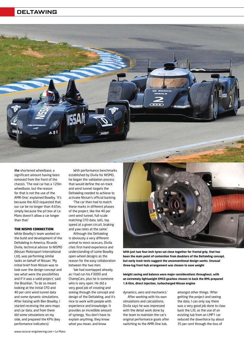
With just two four-inch tyres sat close together for frontal grip, that has
been the main point of contention from doubters of the DeltaWing concept,
but early track tests suggest the unconventional design works. Unusual
three-lug front hub arrangement was chosen to save weight
Weight saving and balance were major considerations throughout, with
an extremely lightweight EMCO gearbox chosen to back the RML-prepared
1.6-litre, direct injection, turbocharged Nissan engine
REV22N5_Delta Wing-MPac.indd 10 21/05/2012 09:07
the tunnel size. The only surprise to me was the exceptional straight-line stability. With a narrow front track, the car does not tramline over bumps in the way a conventional car would.’
In addition to Divila’s technical input, the France-based designer’s experience at La Sarthe should also benefit the team in June. ‘I’ve been racing at Le Mans for decades and have a considerable amount of experience in the set up, preparation and running of a car there, so this is an area that could also be beneficial.’
After incorporating more detail changes related to using the AMR-One tub, Bowlby’s DeltaWing design team, including Simon Marshall and Zack Eakin, along with AAR’s Justin Gurney and John Ward, worked through the manufacturing list to complete the car. With Eakin’s
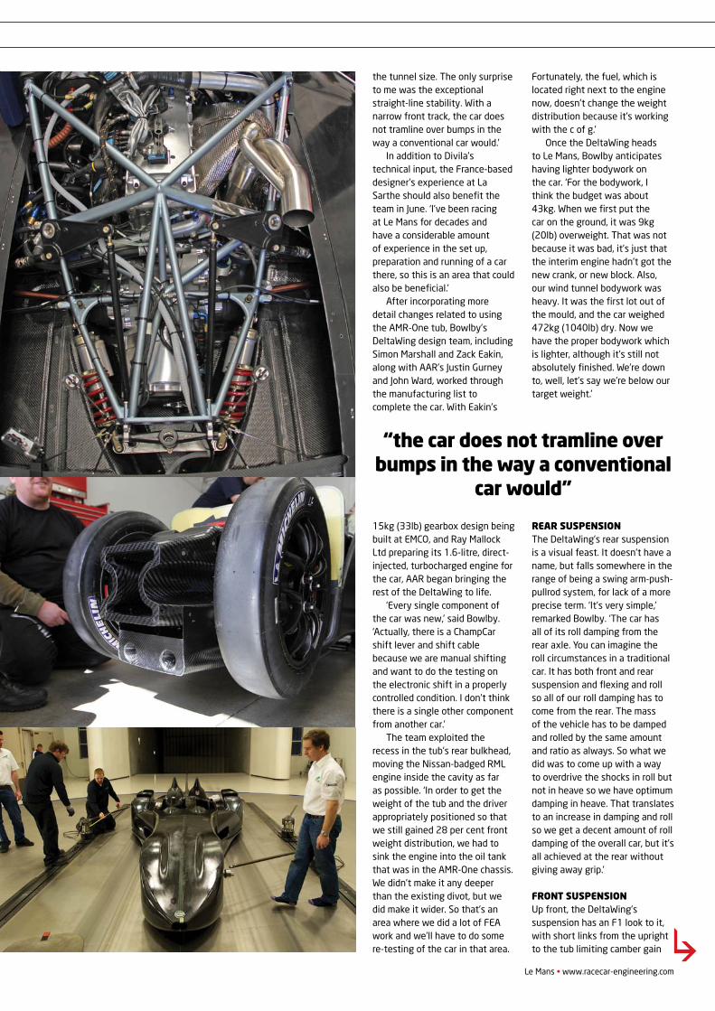
15kg (33lb) gearbox design being built at EMCO, and Ray Mallock Ltd preparing its 1.6-litre, direct-injected, turbocharged engine for the car, AAR began bringing the rest of the DeltaWing to life.
‘Every single component of the car was new,’ said Bowlby. ‘Actually, there is a ChampCar shift lever and shift cable because we are manual shifting and want to do the testing on the electronic shift in a properly controlled condition. I don’t think there is a single other component from another car.’
The team exploited the recess in the tub’s rear bulkhead, moving the Nissan-badged RML engine inside the cavity as far as possible. ‘In order to get the weight of the tub and the driver appropriately positioned so that we still gained 28 per cent front weight distribution, we had to sink the engine into the oil tank that was in the AMR-One chassis. We didn’t make it any deeper than the existing divot, but we did make it wider. So that’s an area where we did a lot of FEA work and we’ll have to do some re-testing of the car in that area.
Fortunately, the fuel, which is located right next to the engine now, doesn’t change the weight distribution because it’s working with the c of g.’
Once the DeltaWing heads to Le Mans, Bowlby anticipates having lighter bodywork on the car. ‘For the bodywork, I think the budget was about 43kg. When we first put the car on the ground, it was 9kg (20lb) overweight. That was not because it was bad, it’s just that the interim engine hadn’t got the new crank, or new block. Also, our wind tunnel bodywork was heavy. It was the first lot out of the mould, and the car weighed 472kg (1040lb) dry. Now we have the proper bodywork which is lighter, although it’s still not absolutely finished. We’re down to, well, let’s say we’re below our target weight.’
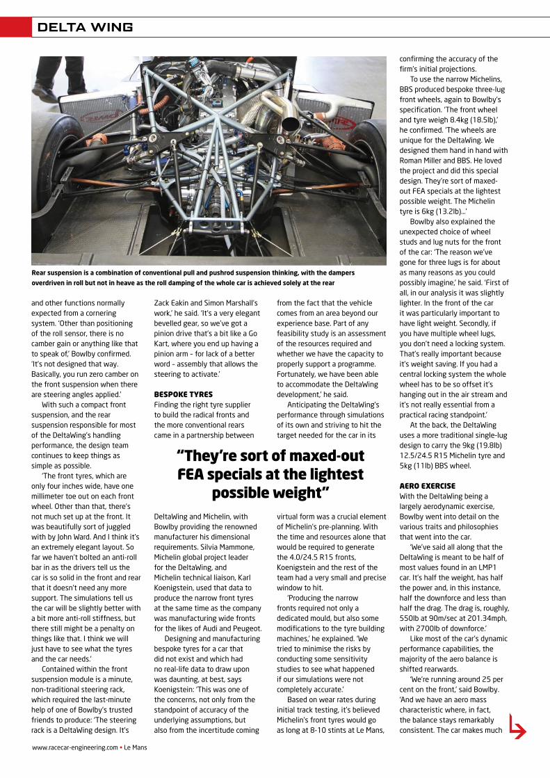
rear suspensionThe DeltaWing’s rear suspension is a visual feast. It doesn’t have a name, but falls somewhere in the range of being a swing arm-push-pullrod system, for lack of a more precise term. ‘It’s very simple,’ remarked Bowlby. ‘The car has all of its roll damping from the rear axle. You can imagine the roll circumstances in a traditional car. It has both front and rear suspension and flexing and roll so all of our roll damping has to come from the rear. The mass of the vehicle has to be damped and rolled by the same amount and ratio as always. So what we did was to come up with a way to overdrive the shocks in roll but not in heave so we have optimum damping in heave. That translates to an increase in damping and roll so we get a decent amount of roll damping of the overall car, but it’s all achieved at the rear without giving away grip.’
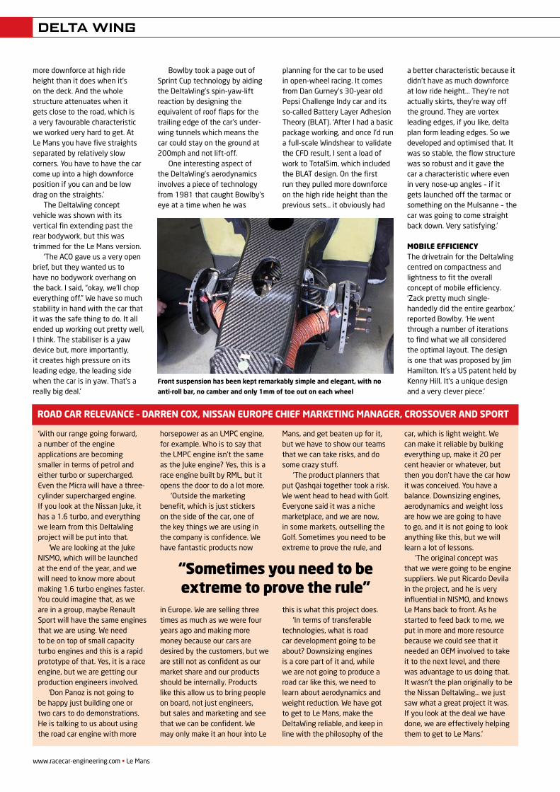
front suspensionUp front, the DeltaWing’s suspension has an F1 look to it, with short links from the upright to the tub limiting camber gain
Le Mans • www.racecar-engineering.com
DELTAWING
“the car does not tramline over bumps in the way a conventional
car would”
REV22N5_Delta Wing-MPac.indd 11 21/05/2012 09:07
www.racecar-engineering.com • Le Mans
DELTA WING
and other functions normally expected from a cornering system. ‘Other than positioning of the roll sensor, there is no camber gain or anything like that to speak of,’ Bowlby confirmed. ‘It’s not designed that way. Basically, you run zero camber on the front suspension when there are steering angles applied.’
With such a compact front suspension, and the rear suspension responsible for most of the DeltaWing’s handling performance, the design team continues to keep things as simple as possible.
‘The front tyres, which are only four inches wide, have one millimeter toe out on each front wheel. Other than that, there’s not much set up at the front. It was beautifully sort of juggled with by John Ward. And I think it’s an extremely elegant layout. So far we haven’t bolted an anti-roll bar in as the drivers tell us the car is so solid in the front and rear that it doesn’t need any more support. The simulations tell us the car will be slightly better with a bit more anti-roll stiffness, but there still might be a penalty on things like that. I think we will just have to see what the tyres and the car needs.’
Contained within the front suspension module is a minute, non-traditional steering rack, which required the last-minute help of one of Bowlby’s trusted friends to produce: ‘The steering rack is a DeltaWing design. It’s
Zack Eakin and Simon Marshall’s work,’ he said. ‘It’s a very elegant bevelled gear, so we’ve got a pinion drive that’s a bit like a Go Kart, where you end up having a pinion arm – for lack of a better word – assembly that allows the steering to activate.’
bespoke tyresFinding the right tyre supplier to build the radical fronts and the more conventional rears came in a partnership between
DeltaWing and Michelin, with Bowlby providing the renowned manufacturer his dimensional requirements. Silvia Mammone, Michelin global project leader for the DeltaWing, and Michelin technical liaison, Karl Koenigstein, used that data to produce the narrow front tyres at the same time as the company was manufacturing wide fronts for the likes of Audi and Peugeot.
Designing and manufacturing bespoke tyres for a car that did not exist and which had no real-life data to draw upon was daunting, at best, says Koenigstein: ‘This was one of the concerns, not only from the standpoint of accuracy of the underlying assumptions, but also from the incertitude coming
from the fact that the vehicle comes from an area beyond our experience base. Part of any feasibility study is an assessment of the resources required and whether we have the capacity to properly support a programme. Fortunately, we have been able to accommodate the DeltaWing development,’ he said.
Anticipating the DeltaWing’s performance through simulations of its own and striving to hit the target needed for the car in its
virtual form was a crucial element of Michelin’s pre-planning. With the time and resources alone that would be required to generate the 4.0/24.5 R15 fronts, Koenigstein and the rest of the team had a very small and precise window to hit.
‘Producing the narrow fronts required not only a dedicated mould, but also some modifications to the tyre building machines,’ he explained. ‘We tried to minimise the risks by conducting some sensitivity studies to see what happened if our simulations were not completely accurate.’
Based on wear rates during initial track testing, it’s believed Michelin’s front tyres would go as long at 8-10 stints at Le Mans,
confirming the accuracy of the firm’s initial projections.
To use the narrow Michelins, BBS produced bespoke three-lug front wheels, again to Bowlby’s specification. ‘The front wheel and tyre weigh 8.4kg (18.5lb),’ he confirmed. ‘The wheels are unique for the DeltaWing. We designed them hand in hand with Roman Miller and BBS. He loved the project and did this special design. They’re sort of maxed-out FEA specials at the lightest possible weight. The Michelin tyre is 6kg (13.2lb)…’
Bowlby also explained the unexpected choice of wheel studs and lug nuts for the front of the car: ‘The reason we’ve gone for three lugs is for about as many reasons as you could possibly imagine,’ he said. ‘First of all, in our analysis it was slightly lighter. In the front of the car it was particularly important to have light weight. Secondly, if you have multiple wheel lugs, you don’t need a locking system. That’s really important because it’s weight saving. If you had a central locking system the whole wheel has to be so offset it’s hanging out in the air stream and it’s not really essential from a practical racing standpoint.’
At the back, the DeltaWing uses a more traditional single-lug design to carry the 9kg (19.8lb) 12.5/24.5 R15 Michelin tyre and 5kg (11lb) BBS wheel.
aero exerciseWith the DeltaWing being a largely aerodynamic exercise, Bowlby went into detail on the various traits and philosophies that went into the car.
‘We’ve said all along that the DeltaWing is meant to be half of most values found in an LMP1 car. It’s half the weight, has half the power and, in this instance, half the downforce and less than half the drag. The drag is, roughly, 550lb at 90m/sec at 201.34mph, with 2700lb of downforce.’
Like most of the car’s dynamic performance capabilities, the majority of the aero balance is shifted rearwards.
‘We’re running around 25 per cent on the front,’ said Bowlby. ‘And we have an aero mass characteristic where, in fact, the balance stays remarkably consistent. The car makes much
Rear suspension is a combination of conventional pull and pushrod suspension thinking, with the dampers
overdriven in roll but not in heave as the roll damping of the whole car is achieved solely at the rear
“they’re sort of maxed-out Fea specials at the lightest
possible weight”
REV22N5_Delta Wing-MPac.indd 12 21/05/2012 09:07
Take cutting-edge wind tunnel technology. Add a 180 mph rolling road.
And build in the best in precision data acquisition capabilities. When we
created the world’s first and finest commercially available full-scale testing
environment of its kind, we did much more than create a new wind tunnel.
We created a new standard in aerodynamics.
1 8 0 m p h w i t h o u t m o v i n g a n i n c h
+1 704 788 9463 info@windshear inc .com w indshear inc .com
Take cutting-edge wind tunnel technology. Add a 180 mph rolling road.
And build in the best in precision data acquisition capabilities. When we
created the world’s first and finest commercially available full-scale testing
environment of its kind, we did much more than create a new wind tunnel.
We created a new standard in aerodynamics.
180 mph without moving an inch
+1 704 788 9463 [email protected] windshearinc.com
WINDSHEAR FPOMAY12.indd 1 03/04/2012 15:58
www.racecar-engineering.com • Le Mans
DELTA WING
more downforce at high ride height than it does when it’s on the deck. And the whole structure attenuates when it gets close to the road, which is a very favourable characteristic we worked very hard to get. At Le Mans you have five straights separated by relatively slow corners. You have to have the car come up into a high downforce position if you can and be low drag on the straights.’
The DeltaWing concept vehicle was shown with its vertical fin extending past the rear bodywork, but this was trimmed for the Le Mans version.
‘The ACO gave us a very open brief, but they wanted us to have no bodywork overhang on the back. I said, “okay, we’ll chop everything off.” We have so much stability in hand with the car that it was the safe thing to do. It all ended up working out pretty well, I think. The stabiliser is a yaw device but, more importantly, it creates high pressure on its leading edge, the leading side when the car is in yaw. That’s a really big deal.’
Bowlby took a page out of Sprint Cup technology by aiding the DeltaWing’s spin-yaw-lift reaction by designing the equivalent of roof flaps for the trailing edge of the car’s under-wing tunnels which means the car could stay on the ground at 200mph and not lift-off.
One interesting aspect of the DeltaWing’s aerodynamics involves a piece of technology from 1981 that caught Bowlby’s eye at a time when he was
planning for the car to be used in open-wheel racing. It comes from Dan Gurney’s 30-year old Pepsi Challenge Indy car and its so-called Battery Layer Adhesion Theory (BLAT). ‘After I had a basic package working, and once I’d run a full-scale Windshear to validate the CFD result, I sent a load of work to TotalSim, which included the BLAT design. On the first run they pulled more downforce on the high ride height than the previous sets… it obviously had
a better characteristic because it didn’t have as much downforce at low ride height... They’re not actually skirts, they’re way off the ground. They are vortex leading edges, if you like, delta plan form leading edges. So we developed and optimised that. It was so stable, the flow structure was so robust and it gave the car a characteristic where even in very nose-up angles – if it gets launched off the tarmac or something on the Mulsanne – the car was going to come straight back down. Very satisfying.’
Mobile efficiencyThe drivetrain for the DeltaWing centred on compactness and lightness to fit the overall concept of mobile efficiency. ‘Zack pretty much single-handedly did the entire gearbox,’ reported Bowlby. ‘He went through a number of iterations to find what we all considered the optimal layout. The design is one that was proposed by Jim Hamilton. It’s a US patent held by Kenny Hill. It’s a unique design and a very clever piece.’
Front suspension has been kept remarkably simple and elegant, with no
anti-roll bar, no camber and only 1mm of toe out on each wheel
‘With our range going forward, a number of the engine applications are becoming smaller in terms of petrol and either turbo or supercharged. Even the Micra will have a three-cylinder supercharged engine. If you look at the Nissan Juke, it has a 1.6 turbo, and everything we learn from this DeltaWing project will be put into that.
‘We are looking at the Juke NISMO, which will be launched at the end of the year, and we will need to know more about making 1.6 turbo engines faster. You could imagine that, as we are in a group, maybe Renault Sport will have the same engines that we are using. We need to be on top of small capacity turbo engines and this is a rapid prototype of that. Yes, it is a race engine, but we are getting our production engineers involved.
‘Don Panoz is not going to be happy just building one or two cars to do demonstrations. He is talking to us about using the road car engine with more
horsepower as an LMPC engine, for example. Who is to say that the LMPC engine isn’t the same as the Juke engine? Yes, this is a race engine built by RML, but it opens the door to do a lot more.
‘Outside the marketing benefit, which is just stickers on the side of the car, one of the key things we are using in the company is confidence. We have fantastic products now
in Europe. We are selling three times as much as we were four years ago and making more money because our cars are desired by the customers, but we are still not as confident as our market share and our products should be internally. Products like this allow us to bring people on board, not just engineers, but sales and marketing and see that we can be confident. We may only make it an hour into Le
Mans, and get beaten up for it, but we have to show our teams that we can take risks, and do some crazy stuff.
‘The product planners that put Qashqai together took a risk. We went head to head with Golf. Everyone said it was a niche marketplace, and we are now, in some markets, outselling the Golf. Sometimes you need to be extreme to prove the rule, and
this is what this project does. ‘In terms of transferable
technologies, what is road car development going to be about? Downsizing engines is a core part of it and, while we are not going to produce a road car like this, we need to learn about aerodynamics and weight reduction. We have got to get to Le Mans, make the DeltaWing reliable, and keep in line with the philosophy of the
car, which is light weight. We can make it reliable by bulking everything up, make it 20 per cent heavier or whatever, but then you don’t have the car how it was conceived. You have a balance. Downsizing engines, aerodynamics and weight loss are how we are going to have to go, and it is not going to look anything like this, but we will learn a lot of lessons.
‘The original concept was that we were going to be engine suppliers. We put Ricardo Devila in the project, and he is very influential in NISMO, and knows Le Mans back to front. As he started to feed back to me, we put in more and more resource because we could see that it needed an OEM involved to take it to the next level, and there was advantage to us doing that. It wasn’t the plan originally to be the Nissan DeltaWing… we just saw what a great project it was. If you look at the deal we have done, we are effectively helping them to get to Le Mans.’
road car relevance – darren cox, nissan europe chieF marketing manager, crossover and sport
“Sometimes you need to be extreme to prove the rule”
REV22N5_Delta Wing-MPac.indd 14 21/05/2012 09:07
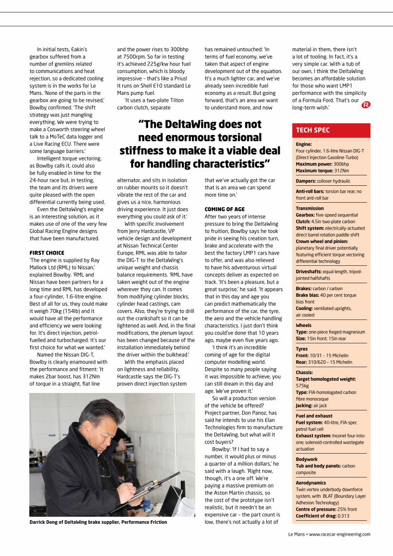
Le Mans • www.racecar-engineering.com
DELTA WING
In initial tests, Eakin’s gearbox suffered from a number of gremlins related to communications and heat rejection, so a dedicated cooling system is in the works for Le Mans. ‘None of the parts in the gearbox are going to be revised,’ Bowlby confirmed. ‘The shift strategy was just mangling everything. We were trying to make a Cosworth steering wheel talk to a MoTeC data logger and a Live Racing ECU. There were some language barriers.’
Intelligent torque vectoring, as Bowlby calls it, could also be fully enabled in time for the 24-hour race but, in testing, the team and its drivers were quite pleased with the open differential currently being used.
Even the DeltaWing’s engine is an interesting solution, as it makes use of one of the very few Global Racing Engine designs that have been manufactured.
first choice‘The engine is supplied by Ray Mallock Ltd (RML) to Nissan,’ explained Bowlby. ‘RML and Nissan have been partners for a long time and RML has developed a four-cylinder, 1.6-litre engine. Best of all for us, they could make it weigh 70kg (154lb) and it would have all the performance and efficiency we were looking for. It’s direct injection, petrol-fuelled and turbocharged. It’s our first choice for what we wanted.’
Named the Nissan DIG-T, Bowlby is clearly enamoured with the performance and fitment: ‘It makes 2bar boost, has 312Nm of torque in a straight, flat line
and the power rises to 300bhp at 7500rpm. So far in testing it’s achieved 225g/kw hour fuel consumption, which is bloody impressive – that’s like a Prius! It runs on Shell E10 standard Le Mans pump fuel.
‘It uses a two-plate Tilton carbon clutch, separate
alternator, and sits in isolation on rubber mounts so it doesn’t vibrate the rest of the car and gives us a nice, harmonious driving experience. It just does everything you could ask of it.’
With specific involvement from Jerry Hardcastle, VP vehicle design and development at Nissan Technical Center Europe, RML was able to tailor the DIG-T to the DeltaWing’s unique weight and chassis balance requirements. ‘RML have taken weight out of the engine wherever they can. It comes from modifying cylinder blocks, cylinder head castings, cam covers. Also, they’re trying to drill out the crankshaft so it can be lightened as well. And, in the final modifications, the plenum layout has been changed because of the installation immediately behind the driver within the bulkhead.’
With the emphasis placed on lightness and reliability, Hardcastle says the DIG-T’s proven direct injection system
has remained untouched: ‘In terms of fuel economy, we’ve taken that aspect of engine development out of the equation. It’s a much lighter car, and we’ve already seen incredible fuel economy as a result. But going forward, that’s an area we want to understand more, and now
that we’ve actually got the car that is an area we can spend more time on.’
coming of ageAfter two years of intense pressure to bring the DeltaWing to fruition, Bowlby says he took pride in seeing his creation turn, brake and accelerate with the best the factory LMP1 cars have to offer, and was also relieved to have his adventurous virtual concepts deliver as expected on track. ‘It’s been a pleasure, but a great surprise,’ he said. ‘It appears that in this day and age you can predict mathematically the performance of the car, the tyre, the aero and the vehicle handling characteristics. I just don’t think you could’ve done that 10 years ago, maybe even five years ago.
‘I think it’s an incredible coming of age for the digital computer modelling world. Despite so many people saying it was impossible to achieve, you can still dream in this day and age. We’ve proven it.’
So will a production version of the vehicle be offered? Project partner, Don Panoz, has said he intends to use his Elan Technologies firm to manufacture the DeltaWing, but what will it cost buyers?
Bowlby: ‘If I had to say a number, it would plus or minus a quarter of a million dollars,’ he said with a laugh. ‘Right now, though, it’s a one off. We’re paying a massive premium on the Aston Martin chassis, so the cost of the prototype isn’t realistic, but it needn’t be an expensive car – the part count is low, there’s not actually a lot of
material in them, there isn’t a lot of tooling. In fact, it’s a very simple car. With a tub of our own, I think the DeltaWing becomes an affordable solution for those who want LMP1 performance with the simplicity of a Formula Ford. That’s our long-term wish.’
Engine: Four cylinder, 1.6-litre Nissan DIG-T (Direct Injection Gasoline-Turbo) Maximum power: 300bhp Maximum torque: 312Nm
Dampers: coilover hydraulic
Anti-roll bars: torsion bar rear; no front anti-roll bar
Transmission Gearbox: five-speed sequential Clutch: 4.5in two-plate carbon Shift system: electrically-actuated direct barrel rotation paddle shift Crown wheel and pinion: planetary final driver potentially featuring efficient torque vectoring differential technology
Driveshafts: equal length, tripod-jointed halfshafts
Brakes: carbon / carbon Brake bias: 40 per cent torque bias front Cooling: ventilated uprights, air cooled
Wheels Type: one-piece forged magnesium Size: 15in front; 15in rear
Tyres Front: 10/31 – 15 Michelin Rear: 310/620 – 15 Michelin
Chassis: Target homologated weight: 575kg Type: FIA-homologated carbon fibre monocoque Jacking: air jack
Fuel and exhaust Fuel system: 40-litre, FIA-spec petrol fuel cell Exhaust system: Inconel four-into-one; solenoid-controlled wastegate actuation
Bodywork Tub and body panels: carbon composite
Aerodynamics Twin vortex underbody downforce system, with BLAT (Boundary Layer Adhesion Technology) Centre of pressure: 25% front Coefficient of drag: 0.313
TECH SPEC
Darrick Dong of DeltaWing brake supplier, Performance Friction
“the DeltaWing does not need enormous torsional
stiffness to make it a viable deal for handling characteristics”
REV22N5_Delta Wing-MPac.indd 15 21/05/2012 09:07
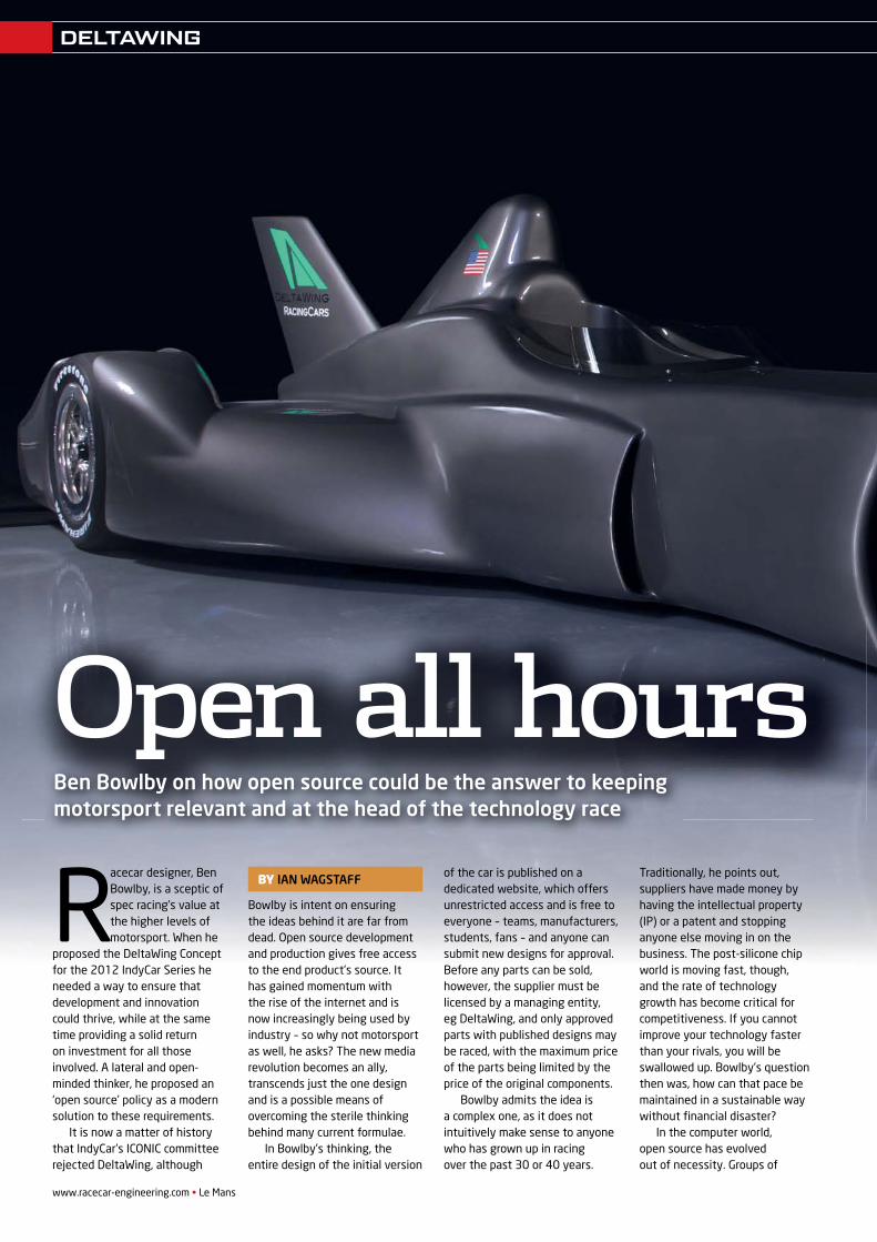
www.racecar-engineering.com • Le Mans
Racecar designer, Ben Bowlby, is a sceptic of spec racing’s value at the higher levels of motorsport. When he
proposed the DeltaWing Concept for the 2012 IndyCar Series he needed a way to ensure that development and innovation could thrive, while at the same time providing a solid return on investment for all those involved. A lateral and open-minded thinker, he proposed an ‘open source’ policy as a modern solution to these requirements.
It is now a matter of history that IndyCar’s ICONIC committee rejected DeltaWing, although
Bowlby is intent on ensuring the ideas behind it are far from dead. Open source development and production gives free access to the end product’s source. It has gained momentum with the rise of the internet and is now increasingly being used by industry – so why not motorsport as well, he asks? The new media revolution becomes an ally, transcends just the one design and is a possible means of overcoming the sterile thinking behind many current formulae.
In Bowlby’s thinking, the entire design of the initial version
of the car is published on a dedicated website, which offers unrestricted access and is free to everyone – teams, manufacturers, students, fans – and anyone can submit new designs for approval. Before any parts can be sold, however, the supplier must be licensed by a managing entity, eg DeltaWing, and only approved parts with published designs may be raced, with the maximum price of the parts being limited by the price of the original components.
Bowlby admits the idea is a complex one, as it does not intuitively make sense to anyone who has grown up in racing over the past 30 or 40 years.
Traditionally, he points out, suppliers have made money by having the intellectual property (IP) or a patent and stopping anyone else moving in on the business. The post-silicone chip world is moving fast, though, and the rate of technology growth has become critical for competitiveness. If you cannot improve your technology faster than your rivals, you will be swallowed up. Bowlby’s question then was, how can that pace be maintained in a sustainable way without fi nancial disaster?
In the computer world, open source has evolved out of necessity. Groups of
Open all hoursBen Bowlby on how open source could be the answer to keeping motorsport relevant and at the head of the technology race
BY IAN WAGSTAFF
DELTAWING
REV21N5_Open Source-MP.GJ.indd 48 21/05/2012 09:27
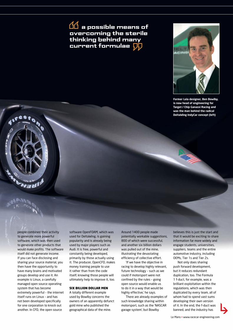
Le Mans • www.racecar-engineering.com
people combined their activity to generate more powerful software, which was then used to generate other products that would make profi ts. The software itself did not generate income. If you can face disclosing and sharing your source material, you then have the opportunity to have many brains and motivated groups develop and use it. An example is Linux, a carefully managed open source operating system that has become extremely powerful – the internet itself runs on Linux – and has not been developed specifi cally for one corporation to knock out another. In CFD, the open source
software OpenFOAM, which was used for DeltaWing, is gaining popularity and is already being used by major players such as Audi. It is free, powerful and constantly being developed, primarily by those actually using it. The producer, OpenCFD, makes money training people to use it rather than from the code itself, knowing those people will ultimately help to improve it, too.
SIX BILLION DOLLAR MENA totally different example used by Bowlby concerns the owners of an apparently defunct gold mine who published the geographical data of the mine.
Around 1400 people made potentially workable suggestions, 800 of which were successful, and another six billion dollars was pulled out of the mine, illustrating the devastating effi ciency of collective effort.
‘If we have the objective in racing to develop highly relevant, future technology – such as we could if motorsport were not confi ned by the rules – going open source would enable us to do it in a way that would be highly effective,’ he says.
There are already examples of such knowledge sharing within motorsport, such as the ‘NASCAR garage system’, but Bowlby
believes this is just the start and that it would be exciting to share information far more widely and engage students, universities, suppliers, teams and the entire automotive industry, including OEMs, Tier 1s and Tier 2s.
Not only does sharing push forward development, but it reduces redundant duplication, too. The Formula 1 f-duct, for example, was a brilliant exploitation within the regulations, which was then duplicated by every team, all of whom had to spend vast sums developing their own version of it. In the end, the f-duct was banned, and the industry has
Former Lola designer, Ben Bowlby, is now head of engineering for Target / Chip Ganassi Racing and was the man behind the radical DeltaWing IndyCar concept (left)
a possible means of overcoming the sterile thinking behind many current formulae
DELTAWING
REV21N5_Open Source-MP.GJ.indd 49 21/05/2012 09:28
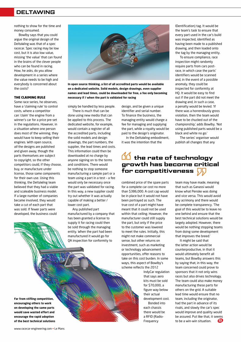
www.racecar-engineering.com • Le Mans
nothing to show for the time and money consumed.
Bowlby says that you could argue the original design of the DeltaWing was that of a spec racecar. Spec racing may be low cost, but it is also low value, missing ‘the value’ that can found in the brains of the clever people who can be found in racing. How, he asks, do you allow development in a series where the value needs to be high and everybody is concerned about the costs?
the claiming ruleSome race series, he observes, have a ‘claiming rule’ to control costs, where a competitor can ‘claim’ the engine from a winner’s car for a price pre-set in the regulations. However, in a situation where one person does most of the winning, they would have to keep selling their engines. With open source, all the designs are published and given away, though the parts themselves are subject to copyright, so the other competitors could, if they choose, buy, or manufacture under license, those same components for their own use. Using this thinking, the DeltaWing team believed that they had a viable and scaleable business model. If a large number of companies became involved, they would take a cut of each part that was sold. If fewer parts were developed, the business could
the rate of technology growth has become critical for competitiveness
In open source thinking, a list of all accredited parts would be available
on a dedicated website. Solid models, design drawings, even supplier
names and lead times, could be downloaded for free, a fee only becoming
necessary if / when the part is validated for racing
Far from stifling competition,
encouraging others to work
on developing the same parts
would save wasted effort and
encourage the rapid adoption
of the best technical solutions
simply be handled by less people.There is much that can be
done using new media that can be applied to this process. The dedicated website, for example, would contain a register of all the accredited parts, including the solid models and design drawings, the part numbers, the supplier, the lead times and costs. This information could then be downloaded at no charge by anyone signing on to the terms and conditions. There would be nothing to stop someone manufacturing a sample part or a team using a part in a test – a fee would only be necessary once the part was validated for racing. In this way, a new supplier could try out whether it was actually capable of making a better / lower cost part.
Any published part manufactured by a company that has been granted a license to supply it for racing could then be sold through the managing entity. When the part had been manufactured it would go for QA inspection for conformity to
design, and be given a unique identifier and serial number. To finance the business, the managing entity would charge a fee for managing and supplying the part, while a royalty would be paid to the design’s originator.
In the DeltaWing embodiment, it was the intention that the
combined price of the spare parts for a complete car cost no more than $386,000. A cost cap would be in place but it would not have been portrayed as such. The true cost of a part might have meant that it could not be used within that ceiling. However, the manufacturer could still supply the part, but only if the price to the customer was lowered to meet the rules. Initially, this might not make commercial sense, but other returns on investment, such as marketing or technology advancement opportunities, offer reasons to take on this cost burden. In some ways, this aspect of Bowlby’s scheme reflects the 2012
IndyCar regulation that says aero kits must be sold for $70,000, a figure way below their actual development cost.
Bonded into each chassis there would be a RFID (Radio-Frequency
IDentification) tag. It would be the team’s task to ensure that every part used in the car’s build was inspected, identified as having been made to a published drawing, and then loaded onto the tag by the managing entity.
To ensure compliance, race inspection might randomly require parts from cars post-race, in which case the parts’ identifiers would be scanned and, in the event of a possible anomaly, they could be inspected for conformity at HQ. It would be easy to find out if the part did not meet the drawing and, in such a case, a penalty would be levied. ‘If there was a horrendously gross violation, then the team would have to be chucked out of the championship,’ adds Bowlby. ‘Not using published parts would be a black and white no go.’
The series’ organiser would publish all changes that any
team may have made, meaning that such as Ganassi would know what Penske was doing and vice versa. This would avoid any acrimony and there would be complete transparency. ‘The goal of this would be to leave no one behind and ensure that the best technical solutions would be largely adopted. However, there would be nothing stopping teams from doing some development that improves the breed.’
It might be said that the latter action would be counterproductive, in that it would ultimately benefit all teams, but Bowlby answers this by saying that, in this way, the team concerned could prove to sponsors that it not only wins races but also drives technology. The team could also make money manufacturing these parts for others on the grid. A suitable lead time would ensure that no team, including the originator, had the part in advance of its rivals, and slowly the car’s spec would improve and quality would be assured. Put like that, it seems to be a win-win situation.
DELTAWING
REV21N5_Open Source-MP.GJ.indd 50 21/05/2012 09:28
Stockistsof highperformancemetals to the world’s most demanding markets
6AL4V 6246
6242 CR14
Bar, Plate & Forgings
Smiths High Performance Unit 0, Stratton Business Park, London Road, Biggleswade, Beds SG18 8QBTel: +44 (0) 1767 604 708 Fax: +44 (0) 1767 312 885
www.smithshp.com
TITANIUM ALLOYS
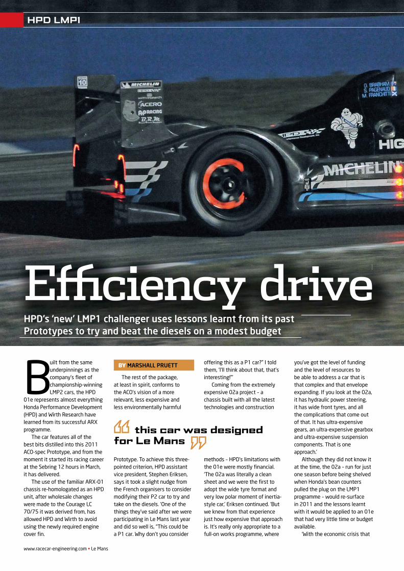
www.racecar-engineering.com • Le Mans
ENGINEERING SOLUTIONS
Built from the same underpinnings as the company’s fl eet of championship-winning LMP2 cars, the HPD
01e represents almost everything Honda Performance Development (HPD) and Wirth Research have learned from its successful ARX programme.
The car features all of the best bits distilled into this 2011 ACO-spec Prototype, and from the moment it started its racing career at the Sebring 12 hours in March, it has delivered.
The use of the familiar ARX-01 chassis re-homologated as an HPD unit, after wholesale changes were made to the Courage LC 70/75 it was derived from, has allowed HPD and Wirth to avoid using the newly required engine cover fi n.
The rest of the package, at least in spirit, conforms to the ACO’s vision of a more relevant, less expensive and less environmentally harmful
Prototype. To achieve this three-pointed criterion, HPD assistant vice president, Stephen Eriksen, says it took a slight nudge from the French organisers to consider modifying their P2 car to try and take on the diesels. ‘One of the things they’ve said after we were participating in Le Mans last year and did so well is, “This could be a P1 car. Why don’t you consider
offering this as a P1 car?” I told them, ‘I’ll think about that, that’s interesting!”’
Coming from the extremely expensive 02a project – a chassis built with all the latest technologies and construction
methods – HPD’s limitations with the 01e were mostly fi nancial. ‘The 02a was literally a clean sheet and we were the fi rst to adopt the wide tyre format and very low polar moment of inertia-style car,’ Eriksen continued. ‘But we knew from that experience just how expensive that approach is. It’s really only appropriate to a full-on works programme, where
you’ve got the level of funding and the level of resources to be able to address a car that is that complex and that envelope expanding. If you look at the 02a, it has hydraulic power steering, it has wide front tyres, and all the complications that come out of that. It has ultra-expensive gears, an ultra-expensive gearbox and ultra-expensive suspension components. That is one approach.’
Although they did not know it at the time, the 02a – run for just one season before being shelved when Honda’s bean counters pulled the plug on the LMP1 programme – would re-surface in 2011 and the lessons learnt with it would be applied to an 01e that had very little time or budget available.
‘With the economic crisis that
E� ciency driveHPD’s ‘new’ LMP1 challenger uses lessons learnt from its past Prototypes to try and beat the diesels on a modest budget
BY MARSHALL PRUETT
this car was designed for Le Mans
HPD LMP1
REV21N6_HPD ARX-mpacs.indd 30 21/05/2012 09:31
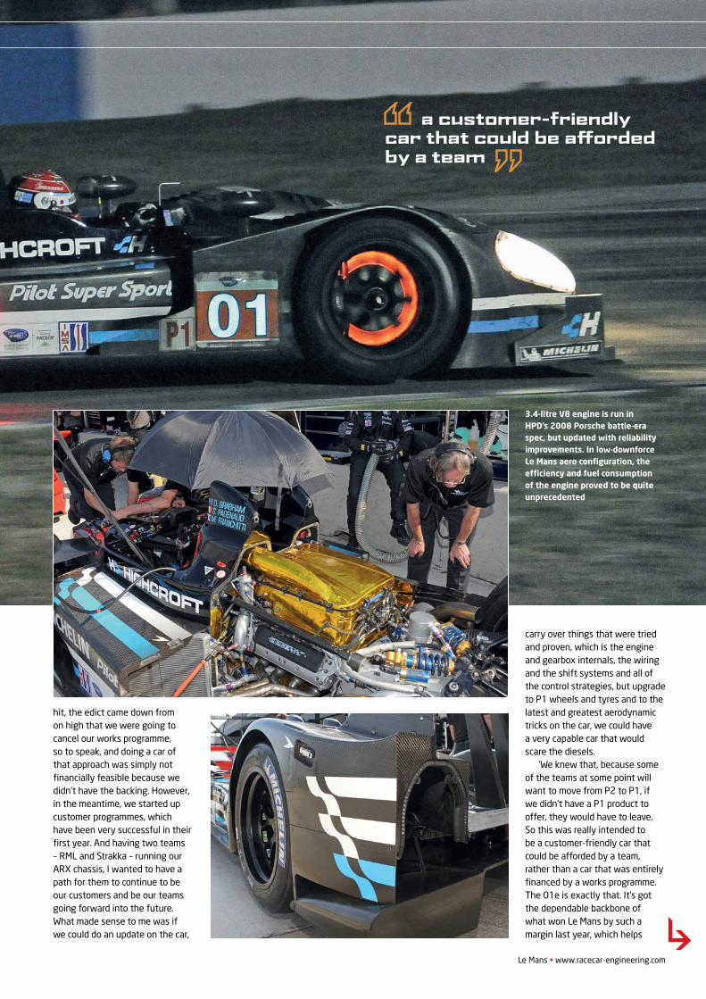
Le Mans • www.racecar-engineering.com
hit, the edict came down from on high that we were going to cancel our works programme, so to speak, and doing a car of that approach was simply not fi nancially feasible because we didn’t have the backing. However, in the meantime, we started up customer programmes, which have been very successful in their fi rst year. And having two teams – RML and Strakka – running our ARX chassis, I wanted to have a path for them to continue to be our customers and be our teams going forward into the future. What made sense to me was if we could do an update on the car,
carry over things that were tried and proven, which is the engine and gearbox internals, the wiring and the shift systems and all of the control strategies, but upgrade to P1 wheels and tyres and to the latest and greatest aerodynamic tricks on the car, we could havea very capable car that would scare the diesels.
‘We knew that, because some of the teams at some point will want to move from P2 to P1, if we didn’t have a P1 product to offer, they would have to leave. So this was really intended to be a customer-friendly car that could be afforded by a team, rather than a car that was entirely fi nanced by a works programme. The 01e is exactly that. It’s got the dependable backbone of what won Le Mans by such a margin last year, which helps
3.4-litre V8 engine is run in HPD’s 2008 Porsche battle-era spec, but updated with reliability improvements. In low-downforce Le Mans aero confi guration, the effi ciency and fuel consumption of the engine proved to be quite unprecedented
a customer-friendly car that could be a� orded by a team
HPD LMP1
REV21N6_HPD ARX-mpacs.indd 31 21/05/2012 09:31
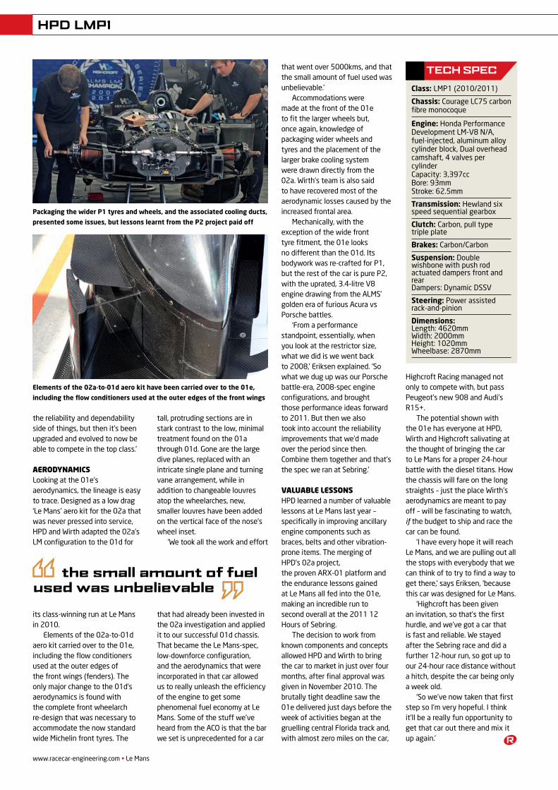
www.racecar-engineering.com • Le Mans
the small amount of fuel used was unbelievable
Elements of the 02a-to-01d aero kit have been carried over to the 01e,
including the flow conditioners used at the outer edges of the front wings
Packaging the wider P1 tyres and wheels, and the associated cooling ducts,
presented some issues, but lessons learnt from the P2 project paid off
the reliability and dependability side of things, but then it’s been upgraded and evolved to now be able to compete in the top class.’
AerodynAmicsLooking at the 01e’s aerodynamics, the lineage is easy to trace. Designed as a low drag ‘Le Mans’ aero kit for the 02a that was never pressed into service, HPD and Wirth adapted the 02a’s LM configuration to the 01d for
its class-winning run at Le Mans in 2010.
Elements of the 02a-to-01d aero kit carried over to the 01e, including the flow conditioners used at the outer edges of the front wings (fenders). The only major change to the 01d’s aerodynamics is found with the complete front wheelarch re-design that was necessary to accommodate the now standard wide Michelin front tyres. The
tall, protruding sections are in stark contrast to the low, minimal treatment found on the 01a through 01d. Gone are the large dive planes, replaced with an intricate single plane and turning vane arrangement, while in addition to changeable louvres atop the wheelarches, new, smaller louvres have been added on the vertical face of the nose’s wheel inset.
‘We took all the work and effort
that had already been invested in the 02a investigation and applied it to our successful 01d chassis. That became the Le Mans-spec, low-downforce configuration, and the aerodynamics that were incorporated in that car allowed us to really unleash the efficiency of the engine to get some phenomenal fuel economy at Le Mans. Some of the stuff we’ve heard from the ACO is that the bar we set is unprecedented for a car
that went over 5000kms, and that the small amount of fuel used was unbelievable.’
Accommodations were made at the front of the 01e to fit the larger wheels but, once again, knowledge of packaging wider wheels and tyres and the placement of the larger brake cooling system were drawn directly from the 02a. Wirth’s team is also said to have recovered most of the aerodynamic losses caused by the increased frontal area.
Mechanically, with the exception of the wide front tyre fitment, the 01e looks no different than the 01d. Its bodywork was re-crafted for P1, but the rest of the car is pure P2, with the uprated, 3.4-litre V8 engine drawing from the ALMS’ golden era of furious Acura vs Porsche battles.
‘From a performance standpoint, essentially, when you look at the restrictor size, what we did is we went back to 2008,’ Eriksen explained. ‘So what we dug up was our Porsche battle-era, 2008-spec engine configurations, and brought those performance ideas forward to 2011. But then we also took into account the reliability improvements that we’d made over the period since then. Combine them together and that’s the spec we ran at Sebring.’
VAluAble lessonsHPD learned a number of valuable lessons at Le Mans last year – specifically in improving ancillary engine components such as braces, belts and other vibration-prone items. The merging of HPD’s 02a project, the proven ARX-01 platform and the endurance lessons gained at Le Mans all fed into the 01e, making an incredible run to second overall at the 2011 12 Hours of Sebring.
The decision to work from known components and concepts allowed HPD and Wirth to bring the car to market in just over four months, after final approval was given in November 2010. The brutally tight deadline saw the 01e delivered just days before the week of activities began at the gruelling central Florida track and, with almost zero miles on the car,
Highcroft Racing managed not only to compete with, but pass Peugeot’s new 908 and Audi’s R15+.
The potential shown with the 01e has everyone at HPD, Wirth and Highcroft salivating at the thought of bringing the car to Le Mans for a proper 24-hour battle with the diesel titans. How the chassis will fare on the long straights – just the place Wirth’s aerodynamics are meant to pay off – will be fascinating to watch, if the budget to ship and race the car can be found.
‘I have every hope it will reach Le Mans, and we are pulling out all the stops with everybody that we can think of to try to find a way to get there,’ says Eriksen, ‘because this car was designed for Le Mans.
‘Highcroft has been given an invitation, so that’s the first hurdle, and we’ve got a car that is fast and reliable. We stayed after the Sebring race and did a further 12-hour run, so got up to our 24-hour race distance without a hitch, despite the car being only a week old.
‘So we’ve now taken that first step so I’m very hopeful. I think it’ll be a really fun opportunity to get that car out there and mix it up again.’
tech spec
Class: LMP1 (2010/2011)
Chassis: Courage LC75 carbon fibre monocoque
Engine: Honda Performance Development LM-V8 N/A, fuel-injected, aluminum alloy cylinder block, Dual overhead camshaft, 4 valves per cylinder Capacity: 3,397cc Bore: 93mm Stroke: 62.5mm
Transmission: Hewland six speed sequential gearbox
Clutch: Carbon, pull type triple plate
Brakes: Carbon/Carbon
Suspension: Double wishbone with push rod actuated dampers front and rear Dampers: Dynamic DSSV
Steering: Power assisted rack-and-pinion
Dimensions: Length: 4620mm Width: 2000mm Height: 1020mm Wheelbase: 2870mm
hpD LMp1
REV21N6_HPD ARX-mpacs.indd 32 21/05/2012 09:34

KONl Race Dampers
In modern racing applications damper sensitivity,
repeatability and ease of use are a must. All KONl
race dampers are specifically designed for these
purposes and have a proven F1 technology. Their
precision adjustment mechanisms allow for maxi-
mum control possible over the damping forces and
operate by closing or opening valve-loaded ports.
KONl race dampers give you best performance
based on more than 50 years of F1 experience.
www.koni.com
your partner from concept to competition
www.racecar-engineering.com • August 2011www.racecar-engineering.com • June 2011
ENGINEERING SOLUTIONSENGINEERING SOLUTIONS
How Aston Martin Racing developed a brand new and highly innovative LMP1 in six months and on a tight budget
BY SAM COLLINS
www.racecar-engineering.com • Le Mans
How Aston Martin Racing developed a
Uncommon engineering
A ston Martin Racing has come in for a lot of criticism over the development of its LMP1 challenger,
the AMR-One, but the team is stoically sticking to its guns and says that by Silverstone’s Intercontinental Le Mans Cup event it will have taken a large step forward. A revised engine design should be in place by then, along with updated aerodynamics, and the team can get on with some serious testing ahead of what should be a more competitive season in 2012.
The Le Mans 24 hours in June was a disappointment for the team, which has developed Prodrive’s fi rst ever ground-up engine and chassis combination in just six months. The team has previously run a modifi ed Lola Prototype alongside its fl eet of
self-developed GT cars but, in September 2010, Aston Martin Racing’s Team Principal George Howard-Chappell was given the green light to develop an all-new car for the new LMP1 formula. ‘We had had three years of experience of the Lola Aston Martin so we could have chosen to run another year with a grandfathered car, but we wanted to control every single design aspect and going for somebody else’s chassis doesn’t give you that freedom,’ said Howard-Chappell. ‘In the past we had our diffi culties with Lola, when you are not in control of the chassis and you can’t decide what to homologate, or can’t do it when you want to. Also, the name above the garage counts.’
OPEN OR CLOSED?Although minor design work had already started when the programme offi cially got off the ground, some key choices were still to be made about the car. ‘There were two fundamental decisions to make and they were whether we would build an open car or a closed car and what kind of power plant we would use,’ said Howard-Chappell. The choices made were controversial – an open-top chassis propelled by a 2.0-litre, turbocharged, in-line six.Although the only other works cars (Peugeot’s 908 and Audi’s R18) built to the new regulations were closed cars, and both manufacturers claim a clear advantage from that format, Howard-Chappell feels differently and claims that tyres were a key factor: ‘Driver changes are massively better in an open car
ASTON MARTIN - AMR-ONE
REV21N8_Aston Martin-MPACS.indd 10 21/05/2012 09:40
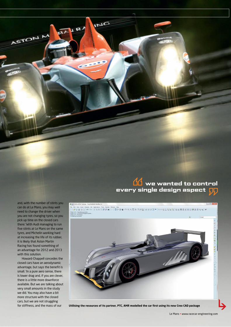
Le Mans • www.racecar-engineering.com
we wanted to control every single design aspect
and, with the number of stints you can do at Le Mans, you may well need to change the driver when you are not changing tyres, so you pick up time on the closed cars there.’ With Audi managing to run fi ve stints at Le Mans on the same tyres, and Michelin working hard at increasing the life of its rubber, it is likely that Aston Martin Racing has found something of an advantage for 2012 and 2013 with this solution.
Howard-Chappell concedes the closed cars have an aerodynamic advantage, but says the benefi t is small. ‘In a pure aero sense, there is lower drag and, if you are clever, there is a little more downforce available. But we are talking about very small amounts in the study we did. You may also have a bit more structure with the closed cars, but we are not struggling for stiffness, and the mass of our Utilising the resources of its partner, PTC, AMR modelled the car fi rst using its new Creo CAD package
ASTON MARTIN - AMR-ONE
REV21N8_Aston Martin-MPACS.indd 11 21/05/2012 09:41
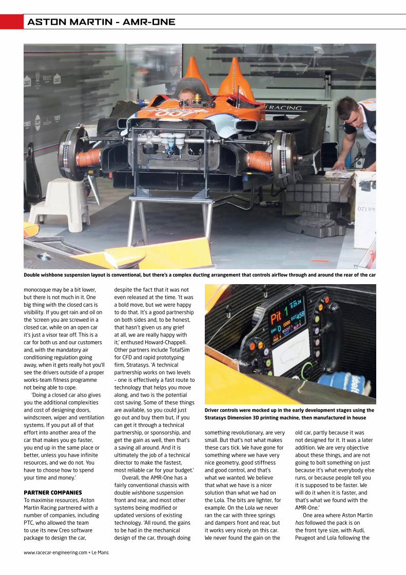
www.racecar-engineering.com • Le Mans
monocoque may be a bit lower, but there is not much in it. One big thing with the closed cars is visibility. If you get rain and oil on the ’screen you are screwed in a closed car, while on an open car it’s just a visor tear off. This is a car for both us and our customers and, with the mandatory air conditioning regulation going away, when it gets really hot you’ll see the drivers outside of a proper works-team fitness programme not being able to cope.
‘Doing a closed car also gives you the additional complexities and cost of designing doors, windscreen, wiper and ventilation systems. If you put all of that effort into another area of the car that makes you go faster, you end up in the same place or better, unless you have infinite resources, and we do not. You have to choose how to spend your time and money.’
Partner comPaniesTo maximise resources, Aston Martin Racing partnered with a number of companies, including PTC, who allowed the team to use its new Creo software package to design the car,
despite the fact that it was not even released at the time. ‘It was a bold move, but we were happy to do that. It’s a good partnership on both sides and, to be honest, that hasn’t given us any grief at all, we are really happy with it,’ enthused Howard-Chappell. Other partners include TotalSim for CFD and rapid prototyping firm, Stratasys. ‘A technical partnership works on two levels – one is effectively a fast route to technology that helps you move along, and two is the potential cost saving. Some of these things are available, so you could just go out and buy them but, if you can get it through a technical partnership, or sponsorship, and get the gain as well, then that’s a saving all around. And it is ultimately the job of a technical director to make the fastest, most reliable car for your budget.’
Overall, the AMR-One has a fairly conventional chassis with double wishbone suspension front and rear, and most other systems being modified or updated versions of existing technology. ‘All round, the gains to be had in the mechanical design of the car, through doing
something revolutionary, are very small. But that’s not what makes these cars tick. We have gone for something where we have very nice geometry, good stiffness and good control, and that’s what we wanted. We believe that what we have is a nicer solution than what we had on the Lola. The bits are lighter, for example. On the Lola we never ran the car with three springs and dampers front and rear, but it works very nicely on this car. We never found the gain on the
old car, partly because it was not designed for it. It was a later addition. We are very objective about these things, and are not going to bolt something on just because it’s what everybody else runs, or because people tell you it is supposed to be faster. We will do it when it is faster, and that’s what we found with the AMR-One.’
One area where Aston Martin has followed the pack is on the front tyre size, with Audi, Peugeot and Lola following the
Double wishbone suspension layout is conventional, but there’s a complex ducting arrangement that controls airflow through and around the rear of the car
Driver controls were mocked up in the early development stages using the
Stratasys Dimension 3D printing machine, then manufactured in house
ASTON MARTIN - AMR-ONE
REV21N8_Aston Martin-MPACS.indd 12 21/05/2012 09:41
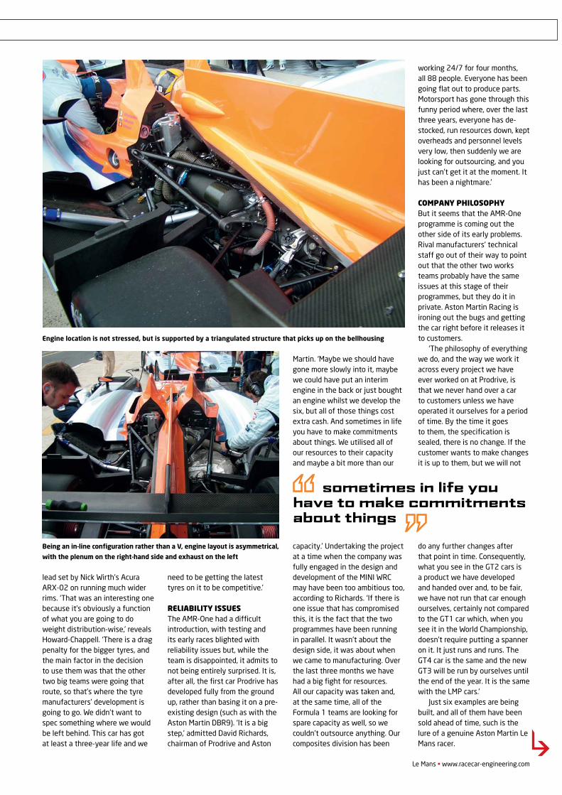
Le Mans • www.racecar-engineering.com
lead set by Nick Wirth’s Acura ARX-02 on running much wider rims. ‘That was an interesting one because it’s obviously a function of what you are going to do weight distribution-wise,’ reveals Howard-Chappell. ‘There is a drag penalty for the bigger tyres, and the main factor in the decision to use them was that the other two big teams were going that route, so that’s where the tyre manufacturers’ development is going to go. We didn’t want to spec something where we would be left behind. This car has got at least a three-year life and we
need to be getting the latest tyres on it to be competitive.’
Reliability issuesThe AMR-One had a difficult introduction, with testing and its early races blighted with reliability issues but, while the team is disappointed, it admits to not being entirely surprised. It is, after all, the first car Prodrive has developed fully from the ground up, rather than basing it on a pre-existing design (such as with the Aston Martin DBR9). ‘It is a big step,’ admitted David Richards, chairman of Prodrive and Aston
Martin. ‘Maybe we should have gone more slowly into it, maybe we could have put an interim engine in the back or just bought an engine whilst we develop the six, but all of those things cost extra cash. And sometimes in life you have to make commitments about things. We utilised all of our resources to their capacity and maybe a bit more than our
capacity.’ Undertaking the project at a time when the company was fully engaged in the design and development of the MINI WRC may have been too ambitious too, according to Richards. ‘If there is one issue that has compromised this, it is the fact that the two programmes have been running in parallel. It wasn’t about the design side, it was about when we came to manufacturing. Over the last three months we have had a big fight for resources. All our capacity was taken and, at the same time, all of the Formula 1 teams are looking for spare capacity as well, so we couldn’t outsource anything. Our composites division has been
working 24/7 for four months, all 88 people. Everyone has been going flat out to produce parts. Motorsport has gone through this funny period where, over the last three years, everyone has de-stocked, run resources down, kept overheads and personnel levels very low, then suddenly we are looking for outsourcing, and you just can’t get it at the moment. It has been a nightmare.’
Company philosophy But it seems that the AMR-One programme is coming out the other side of its early problems. Rival manufacturers’ technical staff go out of their way to point out that the other two works teams probably have the same issues at this stage of their programmes, but they do it in private. Aston Martin Racing is ironing out the bugs and getting the car right before it releases it to customers.
‘The philosophy of everything we do, and the way we work it across every project we have ever worked on at Prodrive, is that we never hand over a car to customers unless we have operated it ourselves for a period of time. By the time it goes to them, the specification is sealed, there is no change. If the customer wants to make changes it is up to them, but we will not
do any further changes after that point in time. Consequently, what you see in the GT2 cars is a product we have developed and handed over and, to be fair, we have not run that car enough ourselves, certainly not compared to the GT1 car which, when you see it in the World Championship, doesn’t require putting a spanner on it. It just runs and runs. The GT4 car is the same and the new GT3 will be run by ourselves until the end of the year. It is the same with the LMP cars.’
Just six examples are being built, and all of them have been sold ahead of time, such is the lure of a genuine Aston Martin Le Mans racer.
sometimes in life you have to make commitments about things
Being an in-line configuration rather than a V, engine layout is asymmetrical,
with the plenum on the right-hand side and exhaust on the left
Engine location is not stressed, but is supported by a triangulated structure that picks up on the bellhousing
ASTON MARTIN - AMR-ONE
REV21N8_Aston Martin-MPACS.indd 13 21/05/2012 09:41
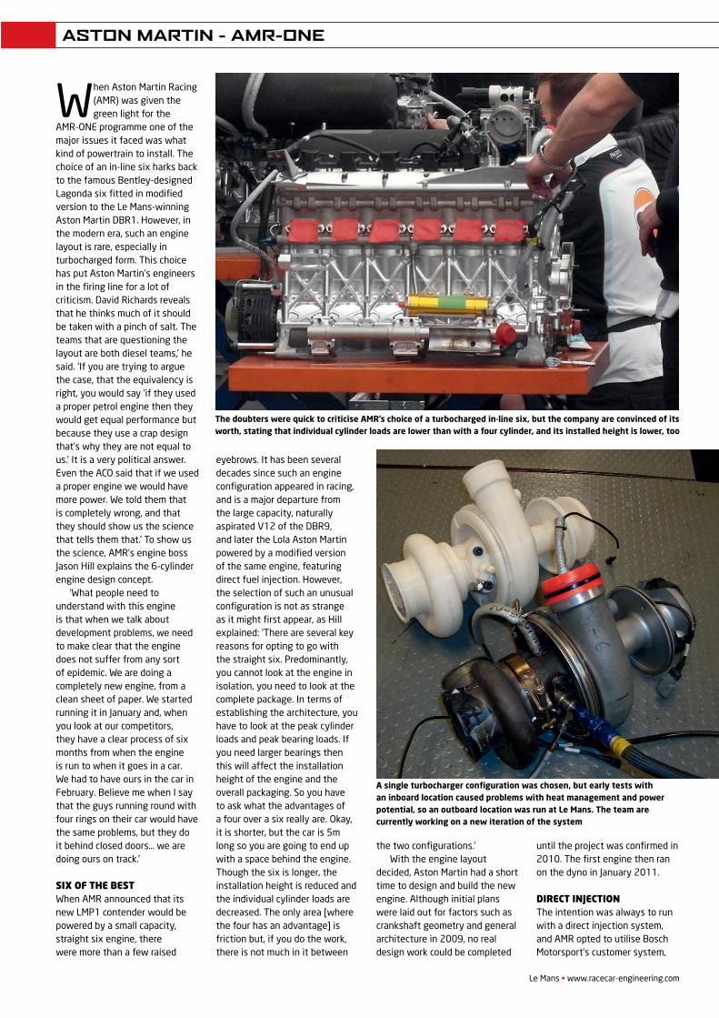
When Aston Martin Racing (AMR) was given the green light for the
AMR-ONE programme one of the major issues it faced was what kind of powertrain to install. The choice of an in-line six harks back to the famous Bentley-designed Lagonda six fitted in modified version to the Le Mans-winning Aston Martin DBR1. However, in the modern era, such an engine layout is rare, especially in turbocharged form. This choice has put Aston Martin’s engineers in the firing line for a lot of criticism. David Richards reveals that he thinks much of it should be taken with a pinch of salt. The teams that are questioning the layout are both diesel teams,’ he said. ‘If you are trying to argue the case, that the equivalency is right, you would say ‘if they used a proper petrol engine then they would get equal performance but because they use a crap design that’s why they are not equal to us.’ It is a very political answer. Even the ACO said that if we used a proper engine we would have more power. We told them that is completely wrong, and that they should show us the science that tells them that.’ To show us the science, AMR’s engine boss Jason Hill explains the 6-cylinder engine design concept.
‘What people need to understand with this engine is that when we talk about development problems, we need to make clear that the engine does not suffer from any sort of epidemic. We are doing a completely new engine, from a clean sheet of paper. We started running it in January and, when you look at our competitors, they have a clear process of six months from when the engine is run to when it goes in a car. We had to have ours in the car in February. Believe me when I say that the guys running round with four rings on their car would have the same problems, but they do it behind closed doors… we are doing ours on track.’
Six of the beStWhen AMR announced that its new LMP1 contender would be powered by a small capacity, straight six engine, there were more than a few raised
eyebrows. It has been several decades since such an engine configuration appeared in racing, and is a major departure from the large capacity, naturally aspirated V12 of the DBR9, and later the Lola Aston Martin powered by a modified version of the same engine, featuring direct fuel injection. However, the selection of such an unusual configuration is not as strange as it might first appear, as Hill explained: ‘There are several key reasons for opting to go with the straight six. Predominantly, you cannot look at the engine in isolation, you need to look at the complete package. In terms of establishing the architecture, you have to look at the peak cylinder loads and peak bearing loads. If you need larger bearings then this will affect the installation height of the engine and the overall packaging. So you have to ask what the advantages of a four over a six really are. Okay, it is shorter, but the car is 5m long so you are going to end up with a space behind the engine. Though the six is longer, the installation height is reduced and the individual cylinder loads are decreased. The only area [where the four has an advantage] is friction but, if you do the work, there is not much in it between
Le Mans • www.racecar-engineering.com
The doubters were quick to criticise AMR’s choice of a turbocharged in-line six, but the company are convinced of its worth, stating that individual cylinder loads are lower than with a four cylinder, and its installed height is lower, too
A single turbocharger configuration was chosen, but early tests with an inboard location caused problems with heat management and power potential, so an outboard location was run at Le Mans. The team are currently working on a new iteration of the system
the two configurations.’ With the engine layout
decided, Aston Martin had a short time to design and build the new engine. Although initial plans were laid out for factors such as crankshaft geometry and general architecture in 2009, no real design work could be completed
until the project was confirmed in 2010. The first engine then ran on the dyno in January 2011.
Direct injection The intention was always to run with a direct injection system, and AMR opted to utilise Bosch Motorsport’s customer system,
ASTON MARTIN - AMR-ONE
REV21N8_Aston Martin-MPACS.indd 15 21/05/2012 09:42
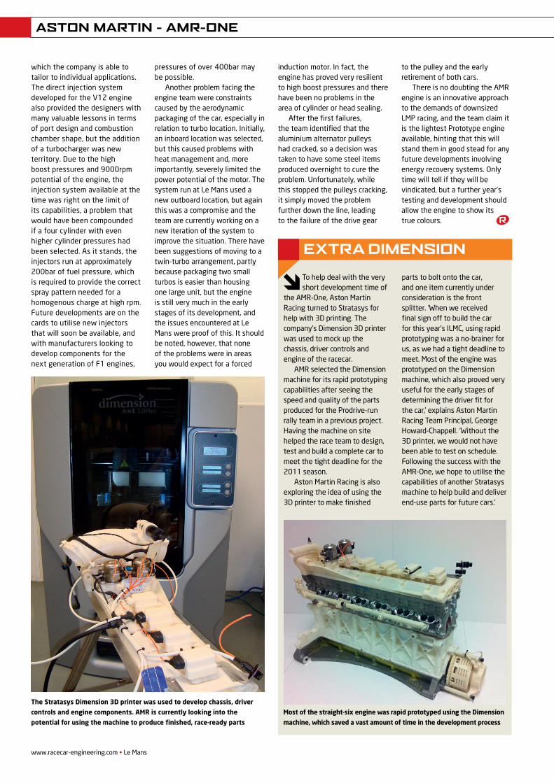
www.racecar-engineering.com • Le Mans
ASTON MARTIN - AMR-ONE
To help deal with the very short development time of
the AMR-One, Aston Martin Racing turned to Stratasys for help with 3D printing. The company’s Dimension 3D printer was used to mock up the chassis, driver controls and engine of the racecar.
AMR selected the Dimension machine for its rapid prototyping capabilities after seeing the speed and quality of the parts produced for the Prodrive-run rally team in a previous project. Having the machine on site helped the race team to design, test and build a complete car to meet the tight deadline for the 2011 season.
Aston Martin Racing is also exploring the idea of using the 3D printer to make finished
parts to bolt onto the car, and one item currently under consideration is the front splitter. ‘When we received final sign off to build the car for this year’s ILMC, using rapid prototyping was a no-brainer for us, as we had a tight deadline to meet. Most of the engine was prototyped on the Dimension machine, which also proved very useful for the early stages of determining the driver fit for the car,’ explains Aston Martin Racing Team Principal, George Howard-Chappell. ‘Without the 3D printer, we would not have been able to test on schedule. Following the success with the AMR-One, we hope to utilise the capabilities of another Stratasys machine to help build and deliver end-use parts for future cars.’
ExTRA DIMENSION
Most of the straight-six engine was rapid prototyped using the Dimension
machine, which saved a vast amount of time in the development process
which the company is able to tailor to individual applications. The direct injection system developed for the V12 engine also provided the designers with many valuable lessons in terms of port design and combustion chamber shape, but the addition of a turbocharger was new territory. Due to the high boost pressures and 9000rpm potential of the engine, the injection system available at the time was right on the limit of its capabilities, a problem that would have been compounded if a four cylinder with even higher cylinder pressures had been selected. As it stands, the injectors run at approximately 200bar of fuel pressure, which is required to provide the correct spray pattern needed for a homogenous charge at high rpm. Future developments are on the cards to utilise new injectors that will soon be available, and with manufacturers looking to develop components for the next generation of F1 engines,
pressures of over 400bar may be possible.
Another problem facing the engine team were constraints caused by the aerodynamic packaging of the car, especially in relation to turbo location. Initially, an inboard location was selected, but this caused problems with heat management and, more importantly, severely limited the power potential of the motor. The system run at Le Mans used a new outboard location, but again this was a compromise and the team are currently working on a new iteration of the system to improve the situation. There have been suggestions of moving to a twin-turbo arrangement, partly because packaging two small turbos is easier than housing one large unit, but the engine is still very much in the early stages of its development, and the issues encountered at Le Mans were proof of this. It should be noted, however, that none of the problems were in areas you would expect for a forced
The Stratasys Dimension 3D printer was used to develop chassis, driver
controls and engine components. AMR is currently looking into the
potential for using the machine to produce finished, race-ready parts
induction motor. In fact, the engine has proved very resilient to high boost pressures and there have been no problems in the area of cylinder or head sealing.
After the first failures, the team identified that the aluminium alternator pulleys had cracked, so a decision was taken to have some steel items produced overnight to cure the problem. Unfortunately, while this stopped the pulleys cracking, it simply moved the problem further down the line, leading to the failure of the drive gear
to the pulley and the early retirement of both cars.
There is no doubting the AMR engine is an innovative approach to the demands of downsized LMP racing, and the team claim it is the lightest Prototype engine available, hinting that this will stand them in good stead for any future developments involving energy recovery systems. Only time will tell if they will be vindicated, but a further year’s testing and development should allow the engine to show its true colours.
REV21N8_Aston Martin-MPACS.indd 16 21/05/2012 09:42
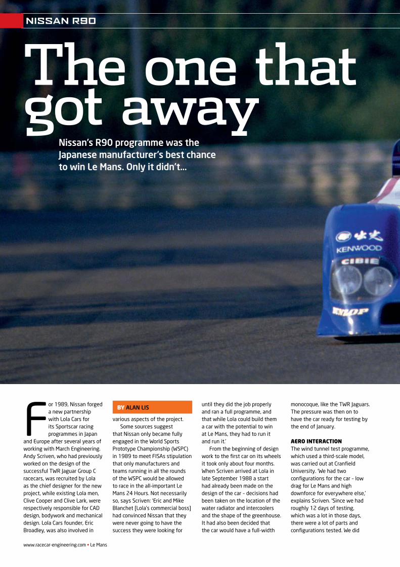
www.racecar-engineering.com • Le Mans
For 1989, Nissan forged a new partnership with Lola Cars for its Sportscar racing programmes in Japan
and Europe after several years of working with March Engineering. Andy Scriven, who had previously worked on the design of the successful TWR Jaguar Group C racecars, was recruited by Lola as the chief designer for the new project, while existing Lola men, Clive Cooper and Clive Lark, were respectively responsible for CAD design, bodywork and mechanical design. Lola Cars founder, Eric Broadley, was also involved in
various aspects of the project.Some sources suggest
that Nissan only became fully engaged in the World Sports Prototype Championship (WSPC) in 1989 to meet FISAs stipulation that only manufacturers and teams running in all the rounds of the WSPC would be allowed to race in the all-important Le Mans 24 Hours. Not necessarily so, says Scriven: ‘Eric and Mike Blanchet [Lola’s commercial boss] had convinced Nissan that they were never going to have the success they were looking for
until they did the job properly and ran a full programme, and that while Lola could build them a car with the potential to win at Le Mans, they had to run it and run it.’
From the beginning of design work to the first car on its wheels it took only about four months. When Scriven arrived at Lola in late September 1988 a start had already been made on the design of the car – decisions had been taken on the location of the water radiator and intercoolers and the shape of the greenhouse. It had also been decided that the car would have a full-width
monocoque, like the TWR Jaguars. The pressure was then on to have the car ready for testing by the end of January.
Aero interActionThe wind tunnel test programme, which used a third-scale model, was carried out at Cranfield University. ‘We had two configurations for the car – low drag for Le Mans and high downforce for everywhere else,’ explains Scriven. ‘Since we had roughly 12 days of testing, which was a lot in those days, there were a lot of parts and configurations tested. We did
Nissan’s R90 programme was the Japanese manufacturer’s best chance to win Le Mans. Only it didn’t…
by ALAN LIS
The one that got away
NISSAN R90
V21N12_Nissan R90-MPAC.indd 44 21/05/2012 09:44
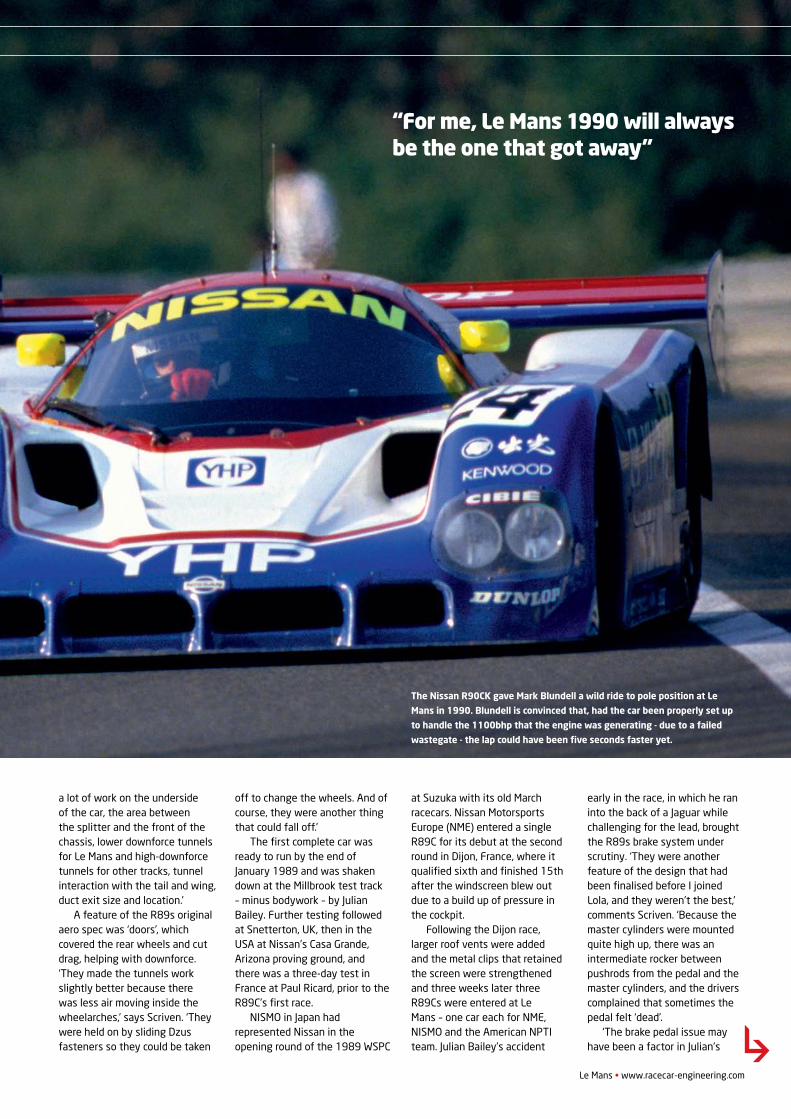
a lot of work on the underside of the car, the area between the splitter and the front of the chassis, lower downforce tunnels for Le Mans and high-downforce tunnels for other tracks, tunnel interaction with the tail and wing, duct exit size and location.’
A feature of the R89s original aero spec was ‘doors’, which covered the rear wheels and cut drag, helping with downforce. ‘They made the tunnels work slightly better because there was less air moving inside the wheelarches,’ says Scriven. ‘They were held on by sliding Dzus fasteners so they could be taken
off to change the wheels. And of course, they were another thing that could fall off.’
The first complete car was ready to run by the end of January 1989 and was shaken down at the Millbrook test track – minus bodywork – by Julian Bailey. Further testing followed at Snetterton, UK, then in the USA at Nissan’s Casa Grande, Arizona proving ground, and there was a three-day test in France at Paul Ricard, prior to the R89C’s first race.
NISMO in Japan had represented Nissan in the opening round of the 1989 WSPC
at Suzuka with its old March racecars. Nissan Motorsports Europe (NME) entered a single R89C for its debut at the second round in Dijon, France, where it qualified sixth and finished 15th after the windscreen blew out due to a build up of pressure in the cockpit.
Following the Dijon race, larger roof vents were added and the metal clips that retained the screen were strengthened and three weeks later three R89Cs were entered at Le Mans – one car each for NME, NISMO and the American NPTI team. Julian Bailey’s accident
early in the race, in which he ran into the back of a Jaguar while challenging for the lead, brought the R89s brake system under scrutiny. ‘They were another feature of the design that had been finalised before I joined Lola, and they weren’t the best,’ comments Scriven. ‘Because the master cylinders were mounted quite high up, there was an intermediate rocker between pushrods from the pedal and the master cylinders, and the drivers complained that sometimes the pedal felt ‘dead’.
‘The brake pedal issue may have been a factor in Julian’s
Le Mans • www.racecar-engineering.com
“For me, Le Mans 1990 will always be the one that got away”
NISSAN R90
The Nissan R90CK gave Mark Blundell a wild ride to pole position at Le
Mans in 1990. Blundell is convinced that, had the car been properly set up
to handle the 1100bhp that the engine was generating - due to a failed
wastegate - the lap could have been five seconds faster yet.
V21N12_Nissan R90-MPAC.indd 45 21/05/2012 09:44
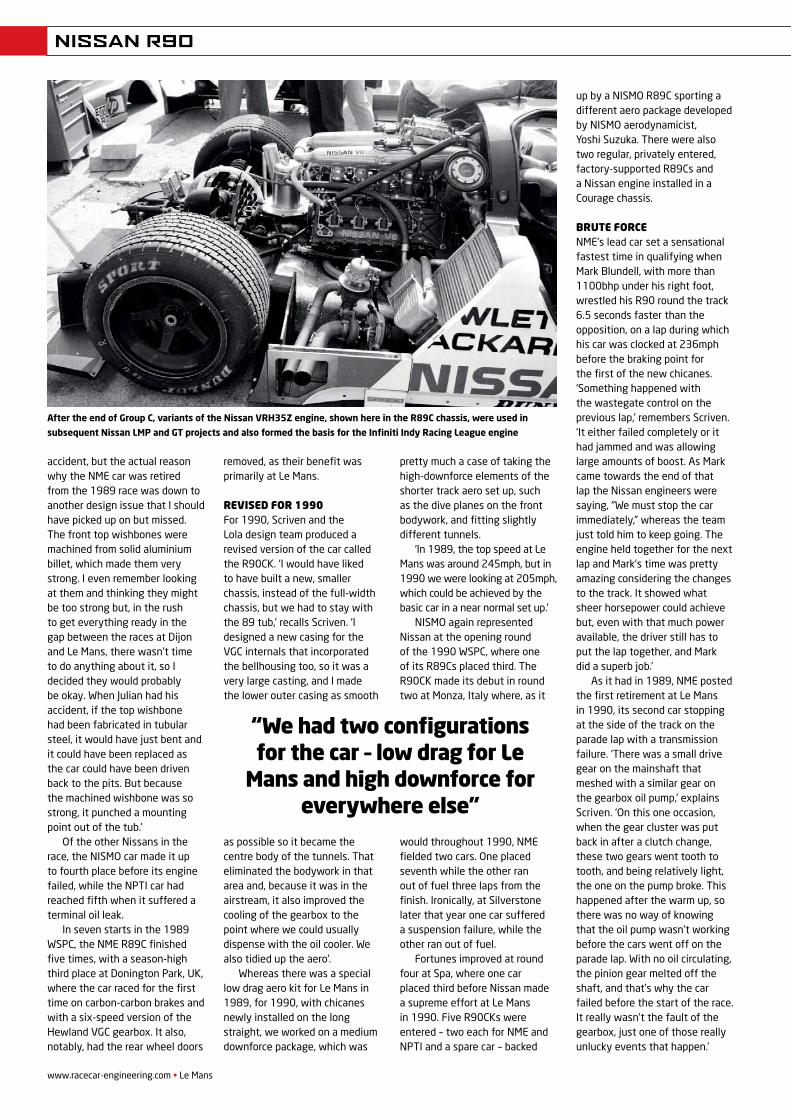
www.racecar-engineering.com • Le Mans
NISSAN R90
accident, but the actual reason why the NME car was retired from the 1989 race was down to another design issue that I should have picked up on but missed. The front top wishbones were machined from solid aluminium billet, which made them very strong. I even remember looking at them and thinking they might be too strong but, in the rush to get everything ready in the gap between the races at Dijon and Le Mans, there wasn’t time to do anything about it, so I decided they would probably be okay. When Julian had his accident, if the top wishbone had been fabricated in tubular steel, it would have just bent and it could have been replaced as the car could have been driven back to the pits. But because the machined wishbone was so strong, it punched a mounting point out of the tub.’
Of the other Nissans in the race, the NISMO car made it up to fourth place before its engine failed, while the NPTI car had reached fifth when it suffered a terminal oil leak.
In seven starts in the 1989 WSPC, the NME R89C finished five times, with a season-high third place at Donington Park, UK, where the car raced for the first time on carbon-carbon brakes and with a six-speed version of the Hewland VGC gearbox. It also, notably, had the rear wheel doors
removed, as their benefit was primarily at Le Mans.
Revised foR 1990 For 1990, Scriven and the Lola design team produced a revised version of the car called the R90CK. ‘I would have liked to have built a new, smaller chassis, instead of the full-width chassis, but we had to stay with the 89 tub,’ recalls Scriven. ‘I designed a new casing for the VGC internals that incorporated the bellhousing too, so it was a very large casting, and I made the lower outer casing as smooth
as possible so it became the centre body of the tunnels. That eliminated the bodywork in that area and, because it was in the airstream, it also improved the cooling of the gearbox to the point where we could usually dispense with the oil cooler. We also tidied up the aero’.
Whereas there was a special low drag aero kit for Le Mans in 1989, for 1990, with chicanes newly installed on the long straight, we worked on a medium downforce package, which was
pretty much a case of taking the high-downforce elements of the shorter track aero set up, such as the dive planes on the front bodywork, and fitting slightly different tunnels.
‘In 1989, the top speed at Le Mans was around 245mph, but in 1990 we were looking at 205mph, which could be achieved by the basic car in a near normal set up.’
NISMO again represented Nissan at the opening round of the 1990 WSPC, where one of its R89Cs placed third. The R90CK made its debut in round two at Monza, Italy where, as it
would throughout 1990, NME fielded two cars. One placed seventh while the other ran out of fuel three laps from the finish. Ironically, at Silverstone later that year one car suffered a suspension failure, while the other ran out of fuel.
Fortunes improved at round four at Spa, where one car placed third before Nissan made a supreme effort at Le Mans in 1990. Five R90CKs were entered – two each for NME and NPTI and a spare car – backed
up by a NISMO R89C sporting a different aero package developed by NISMO aerodynamicist, Yoshi Suzuka. There were also two regular, privately entered, factory-supported R89Cs and a Nissan engine installed in a Courage chassis.
bRute foRceNME’s lead car set a sensational fastest time in qualifying when Mark Blundell, with more than 1100bhp under his right foot, wrestled his R90 round the track 6.5 seconds faster than the opposition, on a lap during which his car was clocked at 236mph before the braking point for the first of the new chicanes. ‘Something happened with the wastegate control on the previous lap,’ remembers Scriven. ‘It either failed completely or it had jammed and was allowing large amounts of boost. As Mark came towards the end of that lap the Nissan engineers were saying, “We must stop the car immediately,” whereas the team just told him to keep going. The engine held together for the next lap and Mark’s time was pretty amazing considering the changes to the track. It showed what sheer horsepower could achieve but, even with that much power available, the driver still has to put the lap together, and Mark did a superb job.’
As it had in 1989, NME posted the first retirement at Le Mans in 1990, its second car stopping at the side of the track on the parade lap with a transmission failure. ‘There was a small drive gear on the mainshaft that meshed with a similar gear on the gearbox oil pump,’ explains Scriven. ‘On this one occasion, when the gear cluster was put back in after a clutch change, these two gears went tooth to tooth, and being relatively light, the one on the pump broke. This happened after the warm up, so there was no way of knowing that the oil pump wasn’t working before the cars went off on the parade lap. With no oil circulating, the pinion gear melted off the shaft, and that’s why the car failed before the start of the race. It really wasn’t the fault of the gearbox, just one of those really unlucky events that happen.’
After the end of Group C, variants of the Nissan VRH35Z engine, shown here in the R89C chassis, were used in
subsequent Nissan LMP and GT projects and also formed the basis for the Infiniti Indy Racing League engine
“We had two configurations for the car – low drag for Le
Mans and high downforce for everywhere else”
V21N12_Nissan R90-MPAC.indd 46 21/05/2012 09:45
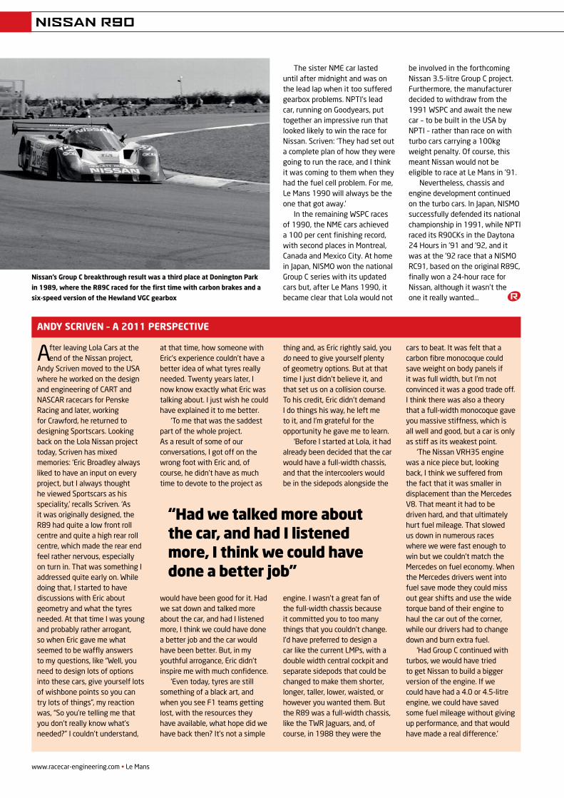
www.racecar-engineering.com • Le Mans
NISSAN R90
The sister NME car lasted until after midnight and was on the lead lap when it too suffered gearbox problems. NPTI’s lead car, running on Goodyears, put together an impressive run that looked likely to win the race for Nissan. Scriven: ‘They had set out a complete plan of how they were going to run the race, and I think it was coming to them when they had the fuel cell problem. For me, Le Mans 1990 will always be the one that got away.’
In the remaining WSPC races of 1990, the NME cars achieved a 100 per cent finishing record, with second places in Montreal, Canada and Mexico City. At home in Japan, NISMO won the national Group C series with its updated cars but, after Le Mans 1990, it became clear that Lola would not
be involved in the forthcoming Nissan 3.5-litre Group C project. Furthermore, the manufacturer decided to withdraw from the 1991 WSPC and await the new car – to be built in the USA by NPTI – rather than race on with turbo cars carrying a 100kg weight penalty. Of course, this meant Nissan would not be eligible to race at Le Mans in ’91.
Nevertheless, chassis and engine development continued on the turbo cars. In Japan, NISMO successfully defended its national championship in 1991, while NPTI raced its R90CKs in the Daytona 24 Hours in ’91 and ’92, and it was at the ’92 race that a NISMO RC91, based on the original R89C, finally won a 24-hour race for Nissan, although it wasn’t the one it really wanted…
After leaving Lola Cars at the end of the Nissan project,
Andy Scriven moved to the USA where he worked on the design and engineering of CART and NASCAR racecars for Penske Racing and later, working for Crawford, he returned to designing Sportscars. Looking back on the Lola Nissan project today, Scriven has mixed memories: ‘Eric Broadley always liked to have an input on every project, but I always thought he viewed Sportscars as his speciality,’ recalls Scriven. ‘As it was originally designed, the R89 had quite a low front roll centre and quite a high rear roll centre, which made the rear end feel rather nervous, especially on turn in. That was something I addressed quite early on. While doing that, I started to have discussions with Eric about geometry and what the tyres needed. At that time I was young and probably rather arrogant, so when Eric gave me what seemed to be waffly answers to my questions, like “Well, you need to design lots of options into these cars, give yourself lots of wishbone points so you can try lots of things”, my reaction was, “So you’re telling me that you don’t really know what’s needed?” I couldn’t understand,
at that time, how someone with Eric’s experience couldn’t have a better idea of what tyres really needed. Twenty years later, I now know exactly what Eric was talking about. I just wish he could have explained it to me better.
‘To me that was the saddest part of the whole project. As a result of some of our conversations, I got off on the wrong foot with Eric and, of course, he didn’t have as much time to devote to the project as
would have been good for it. Had we sat down and talked more about the car, and had I listened more, I think we could have done a better job and the car would have been better. But, in my youthful arrogance, Eric didn’t inspire me with much confidence.
‘Even today, tyres are still something of a black art, and when you see F1 teams getting lost, with the resources they have available, what hope did we have back then? It’s not a simple
thing and, as Eric rightly said, you do need to give yourself plenty of geometry options. But at that time I just didn’t believe it, and that set us on a collision course. To his credit, Eric didn’t demand I do things his way, he left me to it, and I’m grateful for the opportunity he gave me to learn.
‘Before I started at Lola, it had already been decided that the car would have a full-width chassis, and that the intercoolers would be in the sidepods alongside the
engine. I wasn’t a great fan of the full-width chassis because it committed you to too many things that you couldn’t change. I’d have preferred to design a car like the current LMPs, with a double width central cockpit and separate sidepods that could be changed to make them shorter, longer, taller, lower, waisted, or however you wanted them. But the R89 was a full-width chassis, like the TWR Jaguars, and, of course, in 1988 they were the
cars to beat. It was felt that a carbon fibre monocoque could save weight on body panels if it was full width, but I’m not convinced it was a good trade off. I think there was also a theory that a full-width monocoque gave you massive stiffness, which is all well and good, but a car is only as stiff as its weakest point.
‘The Nissan VRH35 engine was a nice piece but, looking back, I think we suffered from the fact that it was smaller in displacement than the Mercedes V8. That meant it had to be driven hard, and that ultimately hurt fuel mileage. That slowed us down in numerous races where we were fast enough to win but we couldn’t match the Mercedes on fuel economy. When the Mercedes drivers went into fuel save mode they could miss out gear shifts and use the wide torque band of their engine to haul the car out of the corner, while our drivers had to change down and burn extra fuel.
‘Had Group C continued with turbos, we would have tried to get Nissan to build a bigger version of the engine. If we could have had a 4.0 or 4.5-litre engine, we could have saved some fuel mileage without giving up performance, and that would have made a real difference.’
Andy scriven – A 2011 PersPecTive
nissan’s Group c breakthrough result was a third place at donington Park
in 1989, where the r89c raced for the first time with carbon brakes and a
six-speed version of the Hewland vGc gearbox
“Had we talked more about the car, and had I listened more, I think we could have done a better job”
V21N12_Nissan R90-MPAC.indd 48 21/05/2012 09:44
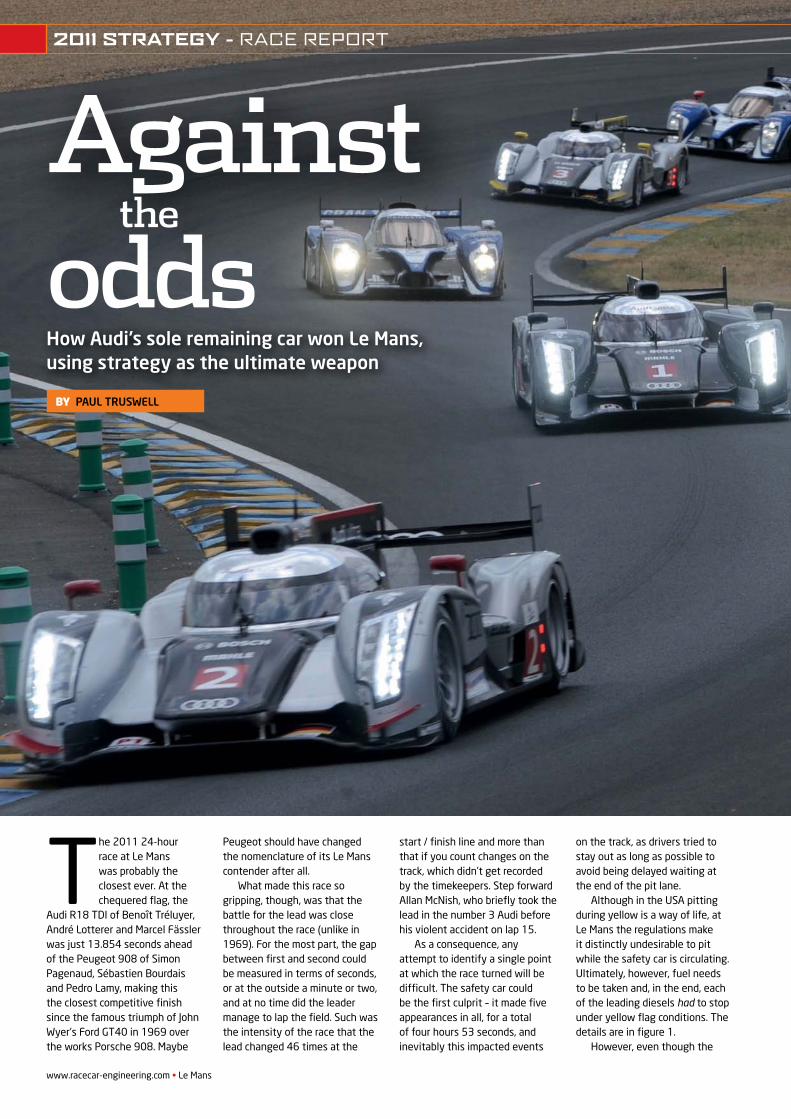
www.racecar-engineering.com • Le Mans
T he 2011 24-hour race at Le Mans was probably the closest ever. At the chequered fl ag, the
Audi R18 TDI of Benoît Tréluyer, André Lotterer and Marcel Fässler was just 13.854 seconds ahead of the Peugeot 908 of Simon Pagenaud, Sébastien Bourdais and Pedro Lamy, making this the closest competitive fi nish since the famous triumph of John Wyer’s Ford GT40 in 1969 over the works Porsche 908. Maybe
Peugeot should have changed the nomenclature of its Le Mans contender after all.
What made this race so gripping, though, was that the battle for the lead was close throughout the race (unlike in 1969). For the most part, the gap between fi rst and second could be measured in terms of seconds, or at the outside a minute or two, and at no time did the leader manage to lap the fi eld. Such was the intensity of the race that the lead changed 46 times at the
start / fi nish line and more than that if you count changes on the track, which didn’t get recorded by the timekeepers. Step forward Allan McNish, who briefl y took the lead in the number 3 Audi before his violent accident on lap 15.
As a consequence, any attempt to identify a single point at which the race turned will be diffi cult. The safety car could be the fi rst culprit – it made fi ve appearances in all, for a total of four hours 53 seconds, and inevitably this impacted events
on the track, as drivers tried to stay out as long as possible to avoid being delayed waiting at the end of the pit lane.
Although in the USA pitting during yellow is a way of life, at Le Mans the regulations make it distinctly undesirable to pit while the safety car is circulating. Ultimately, however, fuel needs to be taken and, in the end, each of the leading diesels had to stop under yellow fl ag conditions. The details are in fi gure 1.
However, even though the
How Audi’s sole remaining car won Le Mans, using strategy as the ultimate weapon
BY PAUL TRUSWELL
Againstodds
the
2011 STRATEGY - RACE REPORT
REV21N8_Le Mans-ACS.indd 32 21/05/2012 09:46
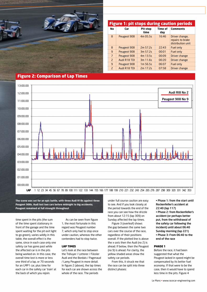
Le Mans • www.racecar-engineering.com
time spent in the pits (the sum of the time spent stationary in front of the garage and the time spent waiting for the pit exit light to go green), varies wildly in this table, the overall effect is the same, since in each case only one safety car has gone past while the affected car is in the pits being worked on. In this case, the overall time lost is more or less one third of a lap, or 70 seconds for an LMP1 car, plus time for each car in the safety car ‘train’ at the back of which you rejoin.
As can be seen from figure 1, the most fortunate in this regard was Peugeot number 7, which only had to stop once under caution, whereas the other contenders had to stop twice.
Lap timesLet’s look at the race between the Tréluyer / Lotterer / Fässler Audi and the Bordais / Pagenaud / Lamy Peugeot in more detail. In figure 2 (above), the lap times for each car are shown across the whole of the race. The periods
under full course caution are easy to see. And if you look closely at the period towards the end of the race you can see how the drizzle from about 12:15 (lap 309) on Sunday affected the lap times.
Figure 3 (overleaf) shows the gap between the same two cars over the course of the race, regardless of their positions overall. If the plotted line is above the x-axis then the Audi (no 2) is ahead. If below, then the Peugeot (no 9) is ahead. For clarity, the yellow shaded areas show the safety car periods.
From this, it struck me that the race can be split into three distinct phases:
• Phase 1: from the start until Rockenfeller’s accident at 22:40 (lap 117)• Phase 2: from Rockenfeller’s accident (or perhaps better put, from the withdrawal of the safety car following the incident) until about 06:40 Sunday morning (lap 221)• Phase 3: From 06:40 to the end of the race
phase 1 Before the race, it had been suggested that what the Peugeot lacked in speed might be compensated by its better fuel economy. If that were to be the case, then it would have to spend less time in the pits. Figure 4
Figure 1: pit stops during caution periodsNo Car Pit stop
timeTime of
dayComments
8 Peugeot 908 4m 05.5s 16:46 Driver change, repairs to brake distribution unit
8 Peugeot 908 2m 57.2s 22:43 Fuel only9 Peugeot 908 3m 57.2s 00:01 Fuel only7 Peugeot 908 4m 13.5s 00:09 Driver change2 Audi R18 TDI 3m 11.6s 00:20 Driver change9 Peugeot 908 1m 56.5s 06:07 Fuel only2 Audi R18 TDI 2m 17.2s 07:58 Driver change
13:00.00
12:00.00
11:00.00
10:00.00
09:00.00
08:00.00
07:00.00
06:00.00
05:00.00
04:00.00
03:00.00
02:00.00
01:00.00
00:00.00
Figure 2: Comparison of Lap times
Audi RI8 No 2
Peugeot 908 No 9
LAP 1 12 23 34 45 56 67 78 89 100 111 122 133 144 155 166 177 188 199 210 221 232 243 254 265 276 287 298 309 320 331 342 353
The scene was set for an epic battle, with three Audi R18s against three
Peugeot 908s. Audi lost two cars before midnight to big accidents;
Peugeot remained at full strength throughout
2011 STRATEGY - RACE REPORT
REV21N8_Le Mans-ACS.indd 33 21/05/2012 09:46
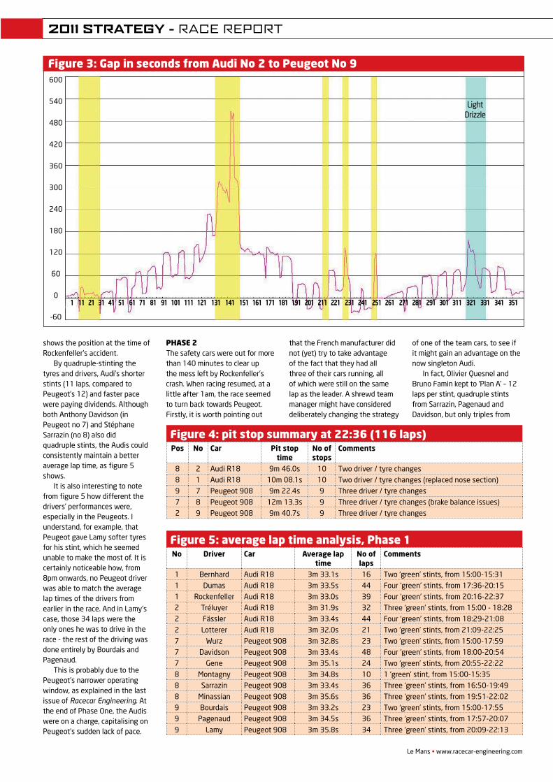
Le Mans • www.racecar-engineering.com 35
shows the position at the time of Rockenfeller’s accident.
By quadruple-stinting the tyres and drivers, Audi’s shorter stints (11 laps, compared to Peugeot’s 12) and faster pace were paying dividends. Although both Anthony Davidson (in Peugeot no 7) and Stéphane Sarrazin (no 8) also did quadruple stints, the Audis could consistently maintain a better average lap time, as figure 5 shows.
It is also interesting to note from figure 5 how different the drivers’ performances were, especially in the Peugeots. I understand, for example, that Peugeot gave Lamy softer tyres for his stint, which he seemed unable to make the most of. It is certainly noticeable how, from 8pm onwards, no Peugeot driver was able to match the average lap times of the drivers from earlier in the race. And in Lamy’s case, those 34 laps were the only ones he was to drive in the race - the rest of the driving was done entirely by Bourdais and Pagenaud.
This is probably due to the Peugeot’s narrower operating window, as explained in the last issue of Racecar Engineering. At the end of Phase One, the Audis were on a charge, capitalising on Peugeot’s sudden lack of pace.
Phase 2The safety cars were out for more than 140 minutes to clear up the mess left by Rockenfeller’s crash. When racing resumed, at a little after 1am, the race seemed to turn back towards Peugeot. Firstly, it is worth pointing out
that the French manufacturer did not (yet) try to take advantage of the fact that they had all three of their cars running, all of which were still on the same lap as the leader. A shrewd team manager might have considered deliberately changing the strategy
of one of the team cars, to see if it might gain an advantage on the now singleton Audi.
In fact, Olivier Quesnel and Bruno Famin kept to ‘Plan A’ – 12 laps per stint, quadruple stints from Sarrazin, Pagenaud and Davidson, but only triples from
Figure 4: pit stop summary at 22:36 (116 laps)Pos No Car Pit stop
timeNo of stops
Comments
8 2 Audi R18 9m 46.0s 10 Two driver / tyre changes8 1 Audi R18 10m 08.1s 10 Two driver / tyre changes (replaced nose section)9 7 Peugeot 908 9m 22.4s 9 Three driver / tyre changes7 8 Peugeot 908 12m 13.3s 9 Three driver / tyre changes (brake balance issues)2 9 Peugeot 908 9m 40.7s 9 Three driver / tyre changes
Figure 5: average lap time analysis, Phase 1No Driver Car Average lap
timeNo of laps
Comments
1 Bernhard Audi R18 3m 33.1s 16 Two ‘green’ stints, from 15:00-15:311 Dumas Audi R18 3m 33.5s 44 Four ‘green’ stints, from 17:36-20:151 Rockenfeller Audi R18 3m 33.0s 39 Four ‘green’ stints, from 20:16-22:372 Tréluyer Audi R18 3m 31.9s 32 Three ‘green’ stints, from 15:00 - 18:282 Fässler Audi R18 3m 33.4s 44 Four ‘green’ stints, from 18:29-21:082 Lotterer Audi R18 3m 32.0s 21 Two ‘green’ stints, from 21:09-22:257 Wurz Peugeot 908 3m 32.8s 23 Two ‘green’ stints, from 15:00-17:597 Davidson Peugeot 908 3m 33.4s 48 Four ‘green’ stints, from 18:00-20:547 Gene Peugeot 908 3m 35.1s 24 Two ‘green’ stints, from 20:55-22:228 Montagny Peugeot 908 3m 34.8s 10 1 ‘green’ stint, from 15:00-15:358 Sarrazin Peugeot 908 3m 33.4s 36 Three ‘green’ stints, from 16:50-19:498 Minassian Peugeot 908 3m 35.6s 36 Three ‘green’ stints, from 19:51-22:029 Bourdais Peugeot 908 3m 33.2s 23 Two ‘green’ stints, from 15:00-17:559 Pagenaud Peugeot 908 3m 34.5s 36 Three ‘green’ stints, from 17:57-20:079 Lamy Peugeot 908 3m 35.8s 34 Three ‘green’ stints, from 20:09-22:13
1 11 21 31 41 51 61 71 81 91 101 111 121 131 141 151 161 171 181 191 201 211 221 231 241 251 261 271 281 291 301 311 321 331 341 351
Light Drizzle
Figure 3: Gap in seconds from audi No 2 to Peugeot No 9600
540
480
420
360
300
240
180
120
60
0
-60
2011 STRATEGY - RACE REPORT
REV21N8_Le Mans-ACS.indd 35 21/05/2012 09:47
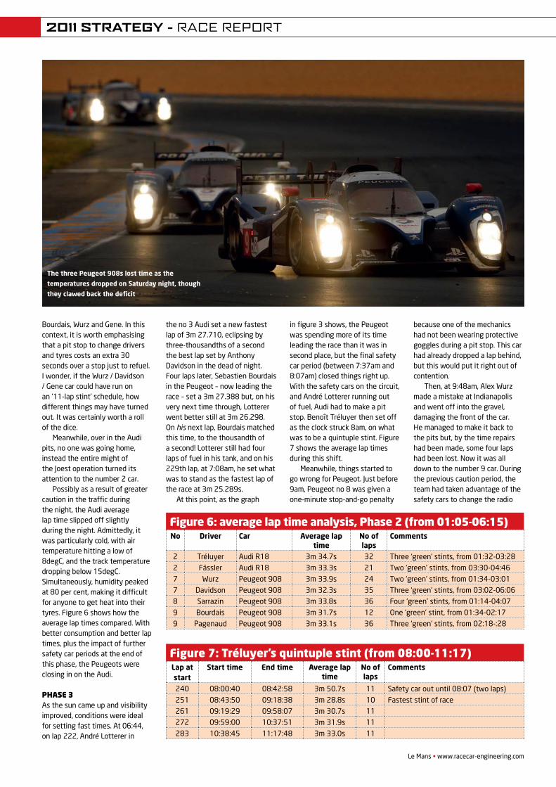
Le Mans • www.racecar-engineering.com
Bourdais, Wurz and Gene. In this context, it is worth emphasising that a pit stop to change drivers and tyres costs an extra 30 seconds over a stop just to refuel. I wonder, if the Wurz / Davidson / Gene car could have run on an ‘11-lap stint’ schedule, how different things may have turned out. It was certainly worth a roll of the dice.
Meanwhile, over in the Audi pits, no one was going home, instead the entire might of the Joest operation turned its attention to the number 2 car.
Possibly as a result of greater caution in the traffic during the night, the Audi average lap time slipped off slightly during the night. Admittedly, it was particularly cold, with air temperature hitting a low of 8degC, and the track temperature dropping below 15degC. Simultaneously, humidity peaked at 80 per cent, making it difficult for anyone to get heat into their tyres. Figure 6 shows how the average lap times compared. With better consumption and better lap times, plus the impact of further safety car periods at the end of this phase, the Peugeots were closing in on the Audi.
Phase 3As the sun came up and visibility improved, conditions were ideal for setting fast times. At 06:44, on lap 222, André Lotterer in
the no 3 Audi set a new fastest lap of 3m 27.710, eclipsing by three-thousandths of a second the best lap set by Anthony Davidson in the dead of night. Four laps later, Sebastien Bourdais in the Peugeot – now leading the race – set a 3m 27.388 but, on his very next time through, Lotterer went better still at 3m 26.298. On his next lap, Bourdais matched this time, to the thousandth of a second! Lotterer still had four laps of fuel in his tank, and on his 229th lap, at 7:08am, he set what was to stand as the fastest lap of the race at 3m 25.289s.
At this point, as the graph
in figure 3 shows, the Peugeot was spending more of its time leading the race than it was in second place, but the final safety car period (between 7:37am and 8:07am) closed things right up. With the safety cars on the circuit, and André Lotterer running out of fuel, Audi had to make a pit stop. Benoît Tréluyer then set off as the clock struck 8am, on what was to be a quintuple stint. Figure 7 shows the average lap times during this shift.
Meanwhile, things started to go wrong for Peugeot. Just before 9am, Peugeot no 8 was given a one-minute stop-and-go penalty
because one of the mechanics had not been wearing protective goggles during a pit stop. This car had already dropped a lap behind, but this would put it right out of contention.
Then, at 9:48am, Alex Wurz made a mistake at Indianapolis and went off into the gravel, damaging the front of the car. He managed to make it back to the pits but, by the time repairs had been made, some four laps had been lost. Now it was all down to the number 9 car. During the previous caution period, the team had taken advantage of the safety cars to change the radio
Figure 6: average lap time analysis, Phase 2 (from 01:05-06:15)No Driver Car Average lap
timeNo of laps
Comments
2 Tréluyer Audi R18 3m 34.7s 32 Three ‘green’ stints, from 01:32-03:282 Fässler Audi R18 3m 33.3s 21 Two ‘green’ stints, from 03:30-04:467 Wurz Peugeot 908 3m 33.9s 24 Two ‘green’ stints, from 01:34-03:017 Davidson Peugeot 908 3m 32.3s 35 Three ‘green’ stints, from 03:02-06:068 Sarrazin Peugeot 908 3m 33.8s 36 Four ‘green’ stints, from 01:14-04:079 Bourdais Peugeot 908 3m 31.7s 12 One ‘green’ stint, from 01:34-02:179 Pagenaud Peugeot 908 3m 33.1s 36 Three ‘green’ stints, from 02:18-:28
Figure 7: Tréluyer’s quintuple stint (from 08:00-11:17)Lap at start
Start time End time Average lap time
No of laps
Comments
240 08:00:40 08:42:58 3m 50.7s 11 Safety car out until 08:07 (two laps)251 08:43:50 09:18:38 3m 28.8s 10 Fastest stint of race261 09:19:29 09:58:07 3m 30.7s 11272 09:59:00 10:37:51 3m 31.9s 11283 10:38:45 11:17:48 3m 33.0s 11
The three Peugeot 908s lost time as the
temperatures dropped on Saturday night, though
they clawed back the deficit
2011 STRATEGY - RACE REPORT
REV21N8_Le Mans-ACS.indd 37 21/05/2012 09:47
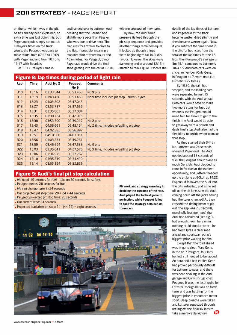
www.racecar-engineering.com • Le Mans38
on the car while it was in the pit. As has already been explained, no extra time was lost doing this, but Pagenaud could simply not match Tréluyer’s times on the track. Worse, the Peugeot was back to triple stints, from 07:45 to 10:09 with Pagenaud and from 10:10 to 12:17 with Bourdais.
At 11:17 Tréluyer came in
and handed over to Lotterer, Audi deciding that the German had slightly more pace than Fässler, who was due to drive next. The plan was for Lotterer to drive to the flag, if possible, meaning a monster stint of three hours and 43 minutes. For Peugeot, Simon Pagenaud would drive the final stint, getting into the car at 12:18,
with no prospect of new tyres.By now, the Audi could
preserve its lead through the pit-stop sequence and, provided all other things remained equal, it looked as though things were beginning to fall in Audi’s favour. However, the skies were darkening and at around 12:15 it started to rain. Figure 8 shows the
details of the lap times of Lotterer and Pagenaud as the track became wetter, dried slightly and then became wetter again. Now, if you subtract the time spent in the pits for both cars from the total of the lap times for the 16 laps, then Pagenaud’s average is 3m 45.1, compared to Lotterer’s 3m 47.5. And both cars were on slicks, remember. (Only Gene, in Peugeot no 7, went onto cut Michelin slick tyres.)
By 13:30, the rain had stopped, and the leading cars were separated by just 15 seconds, with the Audi ahead. Both cars would have to make two more stops for fuel, but whereas the Peugeot would need two full tanks to get to the finish, the Audi would be able to get away with a ‘splash and dash’ final stop. Audi also had the flexibility to decide when to make that stop.
As they started their 344th lap, Lotterer was 24 seconds ahead of Pagenaud. The Audi needed around 15 seconds of fuel, the Peugeot about twice as much. Sensibly, Audi decided to come in for fuel at the earliest opportunity, and Lotterer headed up the pit lane at 60kph at 14:22. Pagenaud followed the Audi into the pits, refuelled, and as he set off up the pit lane, saw the Audi coming down off the jacks having had the tyres changed! As they crossed the timing beam at pit out, the gap was 7.8 seconds, marginally less (perhaps) than Audi had calculated (see fig 9), but enough. From here on in, nothing could stop Lotterer – he had fresh tyres, a clear road ahead and sportscar racing’s biggest prize waiting for him.
Except that the road ahead wasn’t quite clear. Marc Gene, in the no 7 Peugeot, four laps behind, still needed to be lapped. An hour and a half earlier, Gene had proved particularly difficult for Lotterer to pass, and there was head shaking in the Audi garage and Gallic shrugs chez Peugeot. It was the last hurdle for Lotterer, though he was on fresh tyres and was battling for the biggest prize in endurance motor sport. Deep breaths were taken and Lotterer squeezed through, reeling off the final six laps to take a memorable victory.
Figure 9: Audi’s final pit stop calculation• We need: 15 seconds for fuel – take on 20 seconds for safety.
• Peugeot needs: 28 seconds for fuel
• We can change tyres in 24 seconds
• Our projected pit stop time: 20 + 24 = 44 seconds
• Peugeot projected pit stop time: 28 seconds
• Our current lead: 24 seconds.
• Projected lead after pit stop: 24 - (44-28) = eight seconds!
Figure 8: lap times during period of light rainLap Time Audi No 2 Peugeot
No 9Comments
310 12:16 03:33.544 03:53.463 No 9 pits311 12:19 03:43.438 03:53.463 No 9 time includes pit stop - driver / tyres312 12:23 04:03.202 03:47.045313 12:27 03:52.737 03:37.656314 12:31 03:35.863 03:37.084315 12:35 03:38.724 03:42.015316 12:38 03:53.390 03:39.217 No 2 pits317 12:43 04:38.661 03:45.164 No 2 time, includes refuelling pit stop318 12:47 04:02.382 03:56.897319 12:51 04:18.580 04:01.811320 12:56 04:03.231 03:49.261321 12:59 03:46.694 03:47.533 No 9 pits322 13:03 03:35.641 04:27.576 No 9 time, includes refuelling pit stop323 13:06 03:34.975 03:37.767324 13:10 03:35.219 03:34.419325 13:14 03:35.194 03:32.829
Pit work and strategy were key in
deciding the outcome of the race.
Audi played the tactical game to
perfection, while Peugeot failed
to split the strategy between its
three cars
2011 STRATEGY - RACE REPORT
REV21N8_Le Mans-ACS.indd 38 21/05/2012 09:47

want to know more, simply visit:
WHERE SIMPLICITY MEETS INNOVATION
What makes a MoTeC PDM the right choice when wiring your vehicle...
www.motec.com/pdm/racecar
- Continuous retry of failing devices- Fuel pump control and diagnostics- Single press button for headlight flashing- Smart allocation of battery load if alternator fails- Automated stall recovery initiation using Autostart- Itemised view of current draw on devices- Accident auto shutdown- Auto switch to reserve fuel pump- Rain light control for wet weather- Seamless CAN integration (logging and switching)- Diff and gearbox oil pump control- Unique pitlane light control- Programmable thermo fan control - Engine push button start/stop control- Automated intercooler water sprayer- Turbo timer, engine cool down function
as used in:
PDM-RaceCar Engineering V7 1 20/03/12 8:30 AM
CONNECTING INTELLIGENCE
To find out how the quality of your own fluid transfer requirements can be improved, call our Technical Sales Team on
+44 (0) 1753 513080Filtration
Rigid Lines and Swagetite
SERVICES:• 3D cad design service • hose assembly • hard-line manufacture • cnc machining • filtration design • laser marking
PRODUCTS: • Titeflex smoothbore and convoluted hose
products and fittings
• Swagetite fittings and hard-line system solutions
• Pall Filtration systems
• Industria Solenoid valves
Flexible Hose and Fittings
FHS Motor Racing Ltd | 656 Ajax Avenue | Slough, Berkshire | SL1 4BG UK Tel: +44 (0)1753 513080 Fax: +44 (0)1753 513099 Email: [email protected] Web: www.fhsracing.co.uk
Maintaining system integrity, saving weight and cutting costs. Make the connection now.
Interpreting the system requirements of top level motorsport designers takes more than simply applying tried and tested formulae, it takes years of experience and intuitive thinking. Blending this with an unrivalled engineering pedigree helps us produce innovative solutions for customers in F1, endurance and WRC – in fact, every form of motorsport.
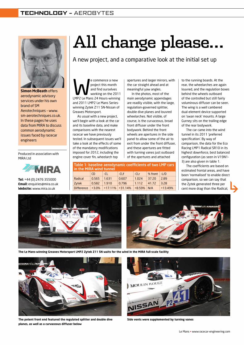
Simon McBeath offers aerodynamic advisory services under his own brand of SM Aerotechniques – www.sm-aerotechniques.co.uk. In these pages he uses data from MIRA to discuss common aerodynamic issues faced by racecar engineers
We commence a new project this month and find ourselves working on the 2011
LMP2 Le Mans 24 Hours-winning and 2011 LMP2 Le Mans Series-winning Zytek Z11 SN-Nissan of Greaves Motorsport.
As usual with a new project, we’ll begin with a look at the car and its baseline data, and make comparisons with the nearest racecar we have previously tested. In subsequent issues we’ll take a look at the effects of some of the mandatory modifications imposed for 2012, including the engine cover fin, wheelarch top
apertures and larger mirrors, with the car straight ahead and at meaningful yaw angles.
In the photos, most of the main aerodynamic appendages are readily visible, with the large, regulation-governed splitter, double dive planes and louvred wheelarches. Not visible, of course, is the curvaceous, broad front diffuser under the front bodywork. Behind the front wheels are apertures in the side panel to allow some of the air to exit from under the front diffuser, and these apertures are fitted with turning vanes just outboard of the apertures and attached
to the running boards. At the rear, the wheelarches are again louvred, and the regulation boxes behind the wheels outboard of the controlled but still fairly voluminous diffuser can be seen. The wing is a well cambered dual-element device supported on ‘swan neck’ mounts. A large Gurney sits on the trailing edge of the rear bodywork.
The car came into the wind tunnel in its 2011 ‘preferred specification’. By way of comparison, the data for the Eco Racing LMP1 Radical SR10 in its highest downforce, best balanced configuration (as seen in V19N1-3) are also given in table 1.
The coefficients are based on estimated frontal areas, and have been ‘normalised’ to enable direct comparison, so we can say that the Zytek generated three per cent more drag than the Radical,
Le Mans • www.racecar-engineering.com
All change please…A new project, and a comparative look at the initial set up
Produced in association with MIRA Ltd
Tel: +44 (0) 2476 355000 Email: [email protected] Website: www.mira.co.uk
The Le Mans-winning Greaves Motorsport LMP2 Zytek Z11 SN waits for the wind in the MIRA full-scale facility
TECHNOLOGY – AEROBYTES
The potent front end featured the regulated splitter and double dive
planes, as well as a curvaceous diffuser below
Table 1: baseline aerodynamic coefficients of two LMP cars in the MIRA wind tunnel
CD -CL -CLf -CLr % front -L/D
Radical 0.565 1.631 0.607 1.024 37.20 2.89
Zytek 0.582 1.910 0.796 1.112 41.72 3.28
Difference +3.0% +17.11% +31.14% +8.59% N/A +13.49%
Side vents were supplemented by turning vanes
REV22N3_Aerobytes-MPAC.indd 47 21/05/2012 09:51
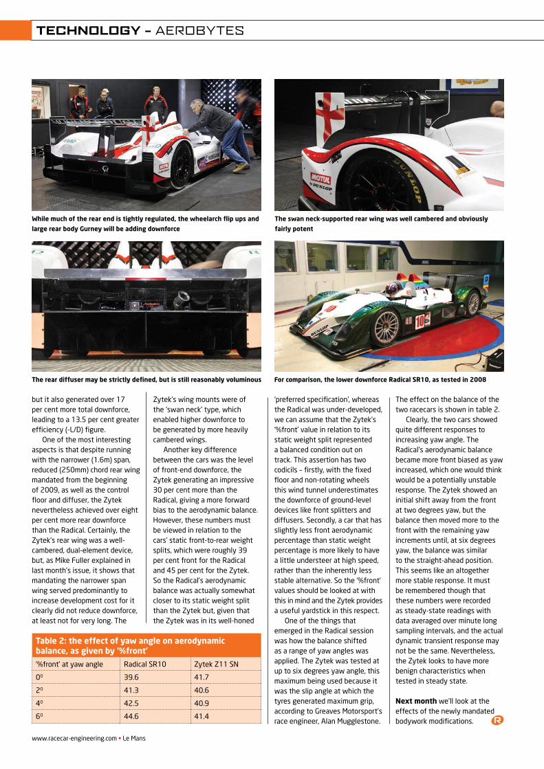
but it also generated over 17 per cent more total downforce, leading to a 13.5 per cent greater efficiency (-L/D) figure.
One of the most interesting aspects is that despite running with the narrower (1.6m) span, reduced (250mm) chord rear wing mandated from the beginning of 2009, as well as the control floor and diffuser, the Zytek nevertheless achieved over eight per cent more rear downforce than the Radical. Certainly, the Zytek’s rear wing was a well-cambered, dual-element device, but, as Mike Fuller explained in last month’s issue, it shows that mandating the narrower span wing served predominantly to increase development cost for it clearly did not reduce downforce, at least not for very long. The
Zytek’s wing mounts were of the ‘swan neck’ type, which enabled higher downforce to be generated by more heavily cambered wings.
Another key difference between the cars was the level of front-end downforce, the Zytek generating an impressive 30 per cent more than the Radical, giving a more forward bias to the aerodynamic balance. However, these numbers must be viewed in relation to the cars’ static front-to-rear weight splits, which were roughly 39 per cent front for the Radical and 45 per cent for the Zytek. So the Radical’s aerodynamic balance was actually somewhat closer to its static weight split than the Zytek but, given that the Zytek was in its well-honed
‘preferred specification’, whereas the Radical was under-developed, we can assume that the Zytek’s ‘%front’ value in relation to its static weight split represented a balanced condition out on track. This assertion has two codicils – firstly, with the fixed floor and non-rotating wheels this wind tunnel underestimates the downforce of ground-level devices like front splitters and diffusers. Secondly, a car that has slightly less front aerodynamic percentage than static weight percentage is more likely to have a little understeer at high speed, rather than the inherently less stable alternative. So the ‘%front’ values should be looked at with this in mind and the Zytek provides a useful yardstick in this respect.
One of the things that emerged in the Radical session was how the balance shifted as a range of yaw angles was applied. The Zytek was tested at up to six degrees yaw angle, this maximum being used because it was the slip angle at which the tyres generated maximum grip, according to Greaves Motorsport’s race engineer, Alan Mugglestone.
The effect on the balance of the two racecars is shown in table 2.
Clearly, the two cars showed quite different responses to increasing yaw angle. The Radical’s aerodynamic balance became more front biased as yaw increased, which one would think would be a potentially unstable response. The Zytek showed an initial shift away from the front at two degrees yaw, but the balance then moved more to the front with the remaining yaw increments until, at six degrees yaw, the balance was similar to the straight-ahead position. This seems like an altogether more stable response. It must be remembered though that these numbers were recorded as steady-state readings with data averaged over minute long sampling intervals, and the actual dynamic transient response may not be the same. Nevertheless, the Zytek looks to have more benign characteristics when tested in steady state.
Next month we’ll look at the effects of the newly mandated bodywork modifications.
While much of the rear end is tightly regulated, the wheelarch flip ups and
large rear body Gurney will be adding downforce
www.racecar-engineering.com • Le Mans
TECHNOLOGY – AEROBYTES
Table 2: the effect of yaw angle on aerodynamic balance, as given by ‘%front’
‘%front’ at yaw angle Radical SR10 Zytek Z11 SN
0O 39.6 41.7
2O 41.3 40.6
4O 42.5 40.9
6O 44.6 41.4
The swan neck-supported rear wing was well cambered and obviously
fairly potent
The rear diffuser may be strictly defined, but is still reasonably voluminous For comparison, the lower downforce Radical SR10, as tested in 2008
REV22N3_Aerobytes-MPAC.indd 48 21/05/2012 09:51
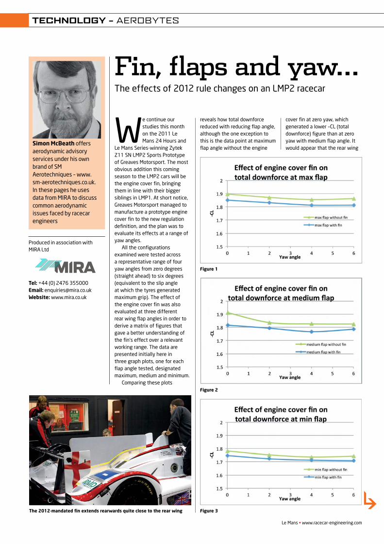
Simon McBeath offers aerodynamic advisory services under his own brand of SM Aerotechniques – www.sm-aerotechniques.co.uk. In these pages he uses data from MIRA to discuss common aerodynamic issues faced by racecar engineers
We continue our studies this month on the 2011 Le Mans 24 Hours and
Le Mans Series-winning Zytek Z11 SN LMP2 Sports Prototype of Greaves Motorsport. The most obvious addition this coming season to the LMP2 cars will be the engine cover fin, bringing them in line with their bigger siblings in LMP1. At short notice, Greaves Motorsport managed to manufacture a prototype engine cover fin to the new regulation definition, and the plan was to evaluate its effects at a range of yaw angles.
All the configurations examined were tested across a representative range of four yaw angles from zero degrees (straight ahead) to six degrees (equivalent to the slip angle at which the tyres generated maximum grip). The effect of the engine cover fin was also evaluated at three different rear wing flap angles in order to derive a matrix of figures that gave a better understanding of the fin’s effect over a relevant working range. The data are presented initially here in three graph plots, one for each flap angle tested, designated maximum, medium and minimum.
Comparing these plots
Le Mans • www.racecar-engineering.com
Fin, flaps and yaw…The effects of 2012 rule changes on an LMP2 racecar
Produced in association with MIRA Ltd
Tel: +44 (0) 2476 355000 Email: [email protected] Website: www.mira.co.uk
TECHNOLOGY – AEROBYTES
Figure 2
Figure 3
reveals how total downforce reduced with reducing flap angle, although the one exception to this is the data point at maximum flap angle without the engine
cover fin at zero yaw, which generated a lower –CL (total downforce) figure than at zero yaw with medium flap angle. It would appear that the rear wing
Figure 1
The 2012-mandated fin extends rearwards quite close to the rear wing
REV22N4_Aerobytes-MPAC.indd 47 21/05/2012 09:51
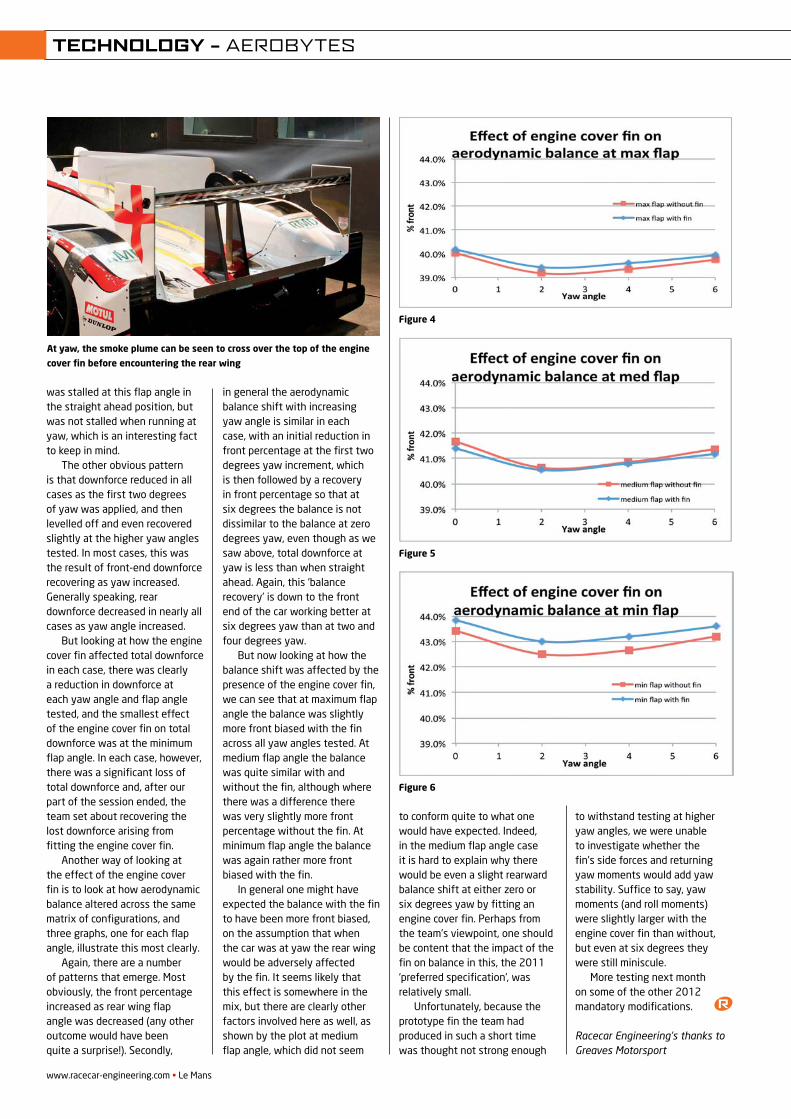
was stalled at this flap angle in the straight ahead position, but was not stalled when running at yaw, which is an interesting fact to keep in mind.
The other obvious pattern is that downforce reduced in all cases as the first two degrees of yaw was applied, and then levelled off and even recovered slightly at the higher yaw angles tested. In most cases, this was the result of front-end downforce recovering as yaw increased. Generally speaking, rear downforce decreased in nearly all cases as yaw angle increased.
But looking at how the engine cover fin affected total downforce in each case, there was clearly a reduction in downforce at each yaw angle and flap angle tested, and the smallest effect of the engine cover fin on total downforce was at the minimum flap angle. In each case, however, there was a significant loss of total downforce and, after our part of the session ended, the team set about recovering the lost downforce arising from fitting the engine cover fin.
Another way of looking at the effect of the engine cover fin is to look at how aerodynamic balance altered across the same matrix of configurations, and three graphs, one for each flap angle, illustrate this most clearly.
Again, there are a number of patterns that emerge. Most obviously, the front percentage increased as rear wing flap angle was decreased (any other outcome would have been quite a surprise!). Secondly,
in general the aerodynamic balance shift with increasing yaw angle is similar in each case, with an initial reduction in front percentage at the first two degrees yaw increment, which is then followed by a recovery in front percentage so that at six degrees the balance is not dissimilar to the balance at zero degrees yaw, even though as we saw above, total downforce at yaw is less than when straight ahead. Again, this ‘balance recovery’ is down to the front end of the car working better at six degrees yaw than at two and four degrees yaw.
But now looking at how the balance shift was affected by the presence of the engine cover fin, we can see that at maximum flap angle the balance was slightly more front biased with the fin across all yaw angles tested. At medium flap angle the balance was quite similar with and without the fin, although where there was a difference there was very slightly more front percentage without the fin. At minimum flap angle the balance was again rather more front biased with the fin.
In general one might have expected the balance with the fin to have been more front biased, on the assumption that when the car was at yaw the rear wing would be adversely affected by the fin. It seems likely that this effect is somewhere in the mix, but there are clearly other factors involved here as well, as shown by the plot at medium flap angle, which did not seem
to conform quite to what one would have expected. Indeed, in the medium flap angle case it is hard to explain why there would be even a slight rearward balance shift at either zero or six degrees yaw by fitting an engine cover fin. Perhaps from the team’s viewpoint, one should be content that the impact of the fin on balance in this, the 2011 ‘preferred specification’, was relatively small.
Unfortunately, because the prototype fin the team had produced in such a short time was thought not strong enough
to withstand testing at higher yaw angles, we were unable to investigate whether the fin’s side forces and returning yaw moments would add yaw stability. Suffice to say, yaw moments (and roll moments) were slightly larger with the engine cover fin than without, but even at six degrees they were still miniscule.
More testing next month on some of the other 2012 mandatory modifications.
Racecar Engineering’s thanks to Greaves Motorsport
www.racecar-engineering.com • Le Mans
TECHNOLOGY – AEROBYTES
At yaw, the smoke plume can be seen to cross over the top of the engine
cover fin before encountering the rear wing
Figure 4
Figure 5
Figure 6
REV22N4_Aerobytes-MPAC.indd 48 21/05/2012 09:52
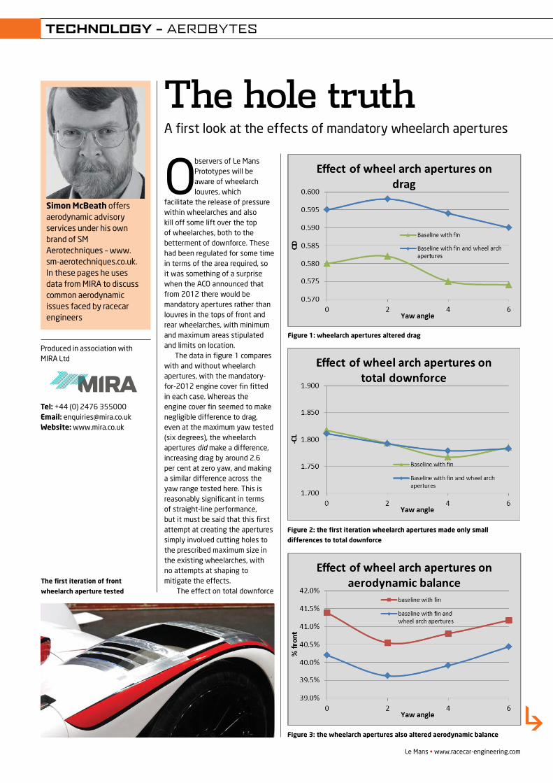
Simon McBeath offers aerodynamic advisory services under his own brand of SM Aerotechniques – www.sm-aerotechniques.co.uk. In these pages he uses data from MIRA to discuss common aerodynamic issues faced by racecar engineers
Observers of Le Mans Prototypes will be aware of wheelarch louvres, which
facilitate the release of pressure within wheelarches and also kill off some lift over the top of wheelarches, both to the betterment of downforce. These had been regulated for some time in terms of the area required, so it was something of a surprise when the ACO announced that from 2012 there would be mandatory apertures rather than louvres in the tops of front and rear wheelarches, with minimum and maximum areas stipulated and limits on location.
The data in fi gure 1 compares with and without wheelarch apertures, with the mandatory-for-2012 engine cover fi n fi tted in each case. Whereas the engine cover fi n seemed to make negligible difference to drag, even at the maximum yaw tested (six degrees), the wheelarch apertures did make a difference, increasing drag by around 2.6 per cent at zero yaw, and making a similar difference across the yaw range tested here. This is reasonably signifi cant in terms of straight-line performance, but it must be said that this fi rst attempt at creating the apertures simply involved cutting holes to the prescribed maximum size in the existing wheelarches, withno attempts at shaping to mitigate the effects.
The effect on total downforce
Le Mans • www.racecar-engineering.com
The hole truthA fi rst look at the effects of mandatory wheelarch apertures
Produced in association with MIRA Ltd
Tel: +44 (0) 2476 355000 Email: [email protected] Website: www.mira.co.uk
TECHNOLOGY – AEROBYTES
The fi rst iteration of front
wheelarch aperture tested
Figure 2: the fi rst iteration wheelarch apertures made only small
differences to total downforce
Figure 3: the wheelarch apertures also altered aerodynamic balance
Figure 1: wheelarch apertures altered drag
REV22N5_Aerobytes-MPac.indd 51 21/05/2012 09:52
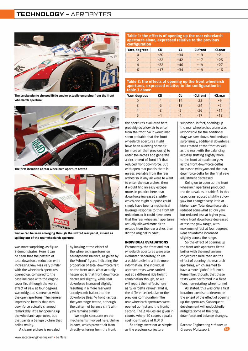
was more surprising, as figure 2 demonstrates. Here it can be seen that the pattern of total downforce reduction with increasing yaw was very similar with the wheelarch apertures opened up, compared to the baseline case with the engine cover fin, although the worst effect of yaw at four degrees was mitigated somewhat with the open apertures. The general impression here is that total downforce actually changed remarkably little by opening up the wheelarch apertures, but that paints a benign picture that belies reality.
A clearer picture is revealed
by looking at the effect of the wheelarch apertures on aerodynamic balance, as given by the ‘%front’ figure, indicating the proportion of total downforce felt on the front axle. What actually happened is that front downforce decreased slightly, while rear downforce increased slightly, resulting in a more rearward aerodynamic balance to the downforce (less ‘% front’) across the yaw range tested, although the pattern of balance shift with yaw remains similar.
We might speculate on the mechanisms involved here. Unlike louvres, which prevent air from directly entering from the front,
the apertures evaluated here probably do allow air to enter from the front. So it would also seem probable that the front wheelarch apertures might have been allowing some air (or more air than previously) to enter the arches and generate an increment of front lift that reduced front downforce. But with open rear panels there is egress available from the rear arches so, if any air were to want to enter the rear arches, then it would find an easy escape route. In practice here, rear downforce increased slightly, which one might suppose could simply have been a mechanical leverage response to the front lift reduction, or it could have been that the rear wheelarch apertures actually allowed more air to escape from the rear arches than did the original louvres.
IndIvIdual evaluatIonsFortunately, the front and rear wheelarch apertures were also evaluated separately, so we are able to divine a little more information. The individual aperture tests were carried out at a different ride height combination though, so we will report their effects here as ‘∆’ or ‘delta values’. That is, the differences relative to the previous configuration. The rear wheelarch apertures were opened up first and the fronts second. The ∆ values are given in counts, where 10 counts equal a coefficient value of 0.010.
So things were not as simple as the previous conjecture
supposed. In fact, opening up the rear wheelarches alone was responsible for the additional drag we saw above. And perhaps surprisingly, additional downforce was created at the front as well as the rear, with the balancing actually shifting slightly more to the front at maximum yaw as the front downforce deltas increased with yaw and the rear downforce delta for the final yaw adjustment decreased.
Going on to open up the front wheelarch apertures produced the delta values in table 2. In this case, drag reduced slightly at low yaw but changed very little at higher yaw. Total downforce also reduced somewhat at low yaw but reduced less at higher yaw, while front downforce decreased across the yaw range, with maximum effect at four degrees. Rear downforce increased slightly across the range.
So the effect of opening up the front arch apertures fitted better with the mechanisms conjectured here than did the effect of opening the rear arch apertures, which seemed to have a more ‘global’ influence. Remember, though, that these tests were performed in a fixed floor, non-rotating wheel tunnel.
As stated, this was only a first iteration exercise to determine the extent of the effect of opening up the apertures. Subsequent development will undoubtedly mitigate some of the drag, downforce and balance changes.
Racecar Engineering’s thanks to Greaves Motorsport.
The first iteration of rear wheelarch aperture tested
www.racecar-engineering.com • Le Mans
TECHNOLOGY – AEROBYTES
The smoke plume showed little smoke actually emerging from the front
wheelarch aperture
Table 1: the effects of opening up the rear wheelarch apertures alone, expressed relative to the previous configurationYaw, degrees CD -CL -CLfront -CLrear
0 +20 +34 +13 +212 +22 +42 +17 +254 +22 +46 +19 +276 +17 +34 +19 +16
Table 2: the effects of opening up the front wheelarch apertures, expressed relative to the configuration in table 1 aboveYaw, degrees CD -CL -CLfront -CLrear
0 -4 -14 -22 +92 -6 -18 -24 +74 -2 -5 -26 +116 +1 -4 -17 +12
Smoke can be seen emerging through the slotted rear panel, as well as
spilling out of the rear wheelarch aperture
REV22N5_Aerobytes-MPac.indd 52 21/05/2012 09:53
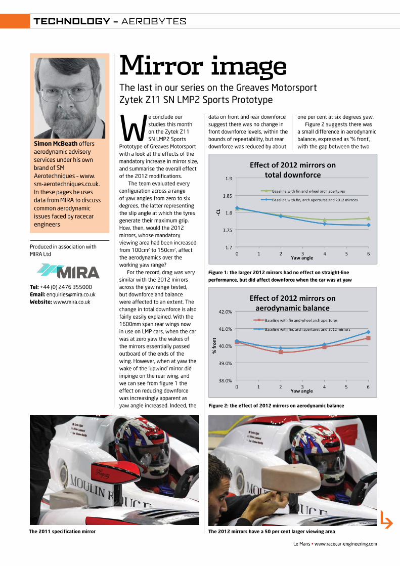
Simon McBeath offers aerodynamic advisory services under his own brand of SM Aerotechniques – www.sm-aerotechniques.co.uk. In these pages he uses data from MIRA to discuss common aerodynamic issues faced by racecar engineers
We conclude our studies this month on the Zytek Z11 SN LMP2 Sports
Prototype of Greaves Motorsport with a look at the effects of the mandatory increase in mirror size, and summarise the overall effect of the 2012 modifications.
The team evaluated every configuration across a range of yaw angles from zero to six degrees, the latter representing the slip angle at which the tyres generate their maximum grip. How, then, would the 2012 mirrors, whose mandatory viewing area had been increased from 100cm2 to 150cm2, affect the aerodynamics over the working yaw range?
For the record, drag was very similar with the 2012 mirrors across the yaw range tested, but downforce and balance were affected to an extent. The change in total downforce is also fairly easily explained. With the 1600mm span rear wings now in use on LMP cars, when the car was at zero yaw the wakes of the mirrors essentially passed outboard of the ends of the wing. However, when at yaw the wake of the ‘upwind’ mirror did impinge on the rear wing, and we can see from figure 1 the effect on reducing downforce was increasingly apparent as yaw angle increased. Indeed, the
data on front and rear downforce suggest there was no change in front downforce levels, within the bounds of repeatability, but rear downforce was reduced by about
one per cent at six degrees yaw.Figure 2 suggests there was
a small difference in aerodynamic balance, expressed as ‘% front’, with the gap between the two
Le Mans • www.racecar-engineering.com
Mirror imageThe last in our series on the Greaves Motorsport Zytek Z11 SN LMP2 Sports Prototype
Produced in association with MIRA Ltd
Tel: +44 (0) 2476 355000 Email: [email protected] Website: www.mira.co.uk
TECHNOLOGY – AEROBYTES
The 2011 specification mirror
Figure 1: the larger 2012 mirrors had no effect on straight-line
performance, but did affect downforce when the car was at yaw
Figure 2: the effect of 2012 mirrors on aerodynamic balance
The 2012 mirrors have a 50 per cent larger viewing area
REV22N6_Aerobytes-MPAC.indd 43 28/05/2012 14:42
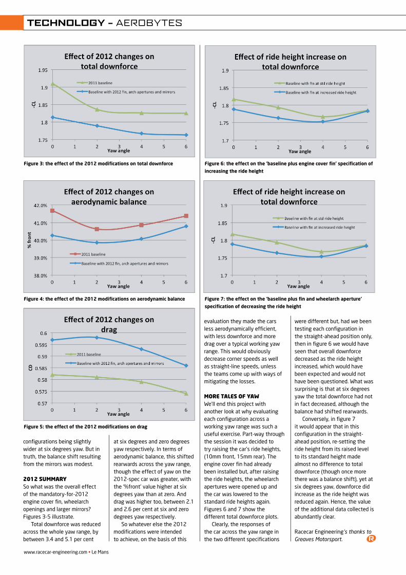
configurations being slightly wider at six degrees yaw. But in truth, the balance shift resulting from the mirrors was modest.
2012 summarySo what was the overall effect of the mandatory-for-2012 engine cover fin, wheelarch openings and larger mirrors? Figures 3-5 illustrate.
Total downforce was reduced across the whole yaw range, by between 3.4 and 5.1 per cent
at six degrees and zero degrees yaw respectively. In terms of aerodynamic balance, this shifted rearwards across the yaw range, though the effect of yaw on the 2012-spec car was greater, with the ‘%front’ value higher at six degrees yaw than at zero. And drag was higher too, between 2.1 and 2.6 per cent at six and zero degrees yaw respectively.
So whatever else the 2012 modifications were intended to achieve, on the basis of this
evaluation they made the cars less aerodynamically efficient, with less downforce and more drag over a typical working yaw range. This would obviously decrease corner speeds as well as straight-line speeds, unless the teams come up with ways of mitigating the losses.
more tales of yawWe’ll end this project with another look at why evaluating each configuration across a working yaw range was such a useful exercise. Part-way through the session it was decided to try raising the car’s ride heights, (10mm front, 15mm rear). The engine cover fin had already been installed but, after raising the ride heights, the wheelarch apertures were opened up and the car was lowered to the standard ride heights again. Figures 6 and 7 show the different total downforce plots.
Clearly, the responses of the car across the yaw range in the two different specifications
were different but, had we been testing each configuration in the straight-ahead position only, then in figure 6 we would have seen that overall downforce decreased as the ride height increased, which would have been expected and would not have been questioned. What was surprising is that at six degrees yaw the total downforce had not in fact decreased, although the balance had shifted rearwards.
Conversely, in figure 7 it would appear that in this configuration in the straight-ahead position, re-setting the ride height from its raised level to its standard height made almost no difference to total downforce (though once more there was a balance shift), yet at six degrees yaw, downforce did increase as the ride height was reduced again. Hence, the value of the additional data collected is abundantly clear.
Racecar Engineering’s thanks to Greaves Motorsport.
Figure 5: the effect of the 2012 modifications on drag
www.racecar-engineering.com • Le Mans
TECHNOLOGY – AEROBYTES
Figure 4: the effect of the 2012 modifications on aerodynamic balance
Figure 6: the effect on the ‘baseline plus engine cover fin’ specification of
increasing the ride height
Figure 7: the effect on the ‘baseline plus fin and wheelarch aperture’
specification of decreasing the ride height
Figure 3: the effect of the 2012 modifications on total downforce
REV22N6_Aerobytes-MPAC.indd 44 28/05/2012 14:42
“Aerodynamics is a decisive factor. We count on RUAG’s testing expertise.”
Accuracy, efficiency, competence and
flexibility: This is what you expect from
aerodynamic specialists. And this is
what RUAG stands for. Whether you
are planning to outsource your full
aerodynamic development, whether
you require high quality wind tunnel
test data or just need a high precision
strain gauge balance: Our state-of-the-
art equipment and highly skilled staff
provides the perfect solution. The OAK
Racing-Team put us to the test. When
will you?
RUAG Switzerland AGRUAG Aviation Aerodynamics Department 6032 Emmen | Switzerland Phone +41 41 268 38 01 [email protected] www.ruag.com/aviation
Bertrand Baguette, Driver OAK Racing-Team
Pho
to M
arku
s B
erg
er
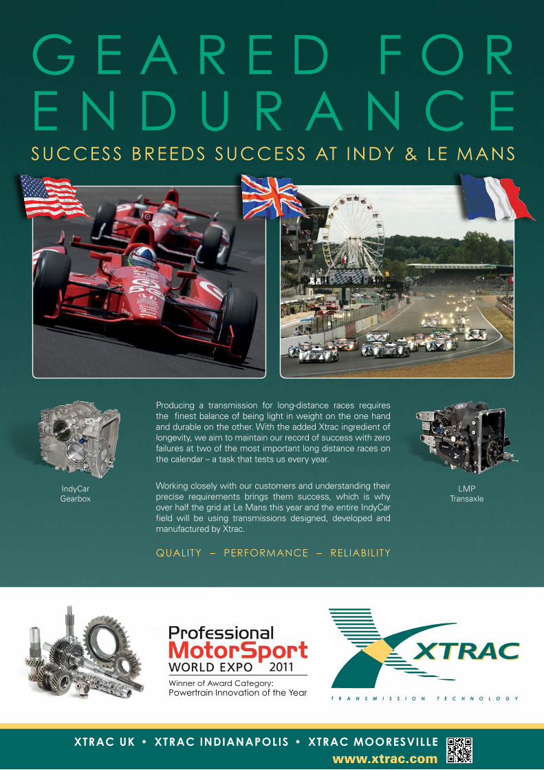
G E A R E D F O RE N D U R A N C ESUCCESS BREEDS SUCCESS AT INDY & LE MANS
Producing a transmission for long-distance races requires the finest balance of being light in weight on the one hand and durable on the other. With the added Xtrac ingredient of longevity, we aim to maintain our record of success with zero failures at two of the most important long distance races on the calendar – a task that tests us every year. Working closely with our customers and understanding their precise requirements brings them success, which is why over half the grid at Le Mans this year and the entire IndyCar field will be using transmissions designed, developed and manufactured by Xtrac.
QUALITY – PERFORMANCE – RELIABILITY
IndyCar Gearbox
LMP Transaxle
Winner of Award Category:Powertrain Innovation of the Year
www.xtrac.comXTRAC UK • XTRAC INDIANAPOLIS • XTRAC MOORESVILLE
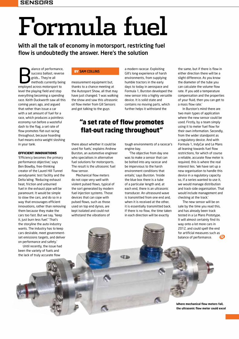
B alance of performance, success ballast, reverse grids… They’re all methods currently being
employed across motorsport to level the playing field and stop everything becoming a spending race. Keith Duckworth saw all this coming years ago, and argued that rather than issue a car with a set amount of fuel for a race, which produces a pointless economy run before a wasteful dash to the flag, a set rate of flow promotes flat-out racing throughout, because hoarding fuel means extra weight sloshing in your tank.
EfficiEnt innovations‘Efficiency becomes the primary performance objective,’ says Ben Bowlby, free-thinking creator of the Laurel Hill Tunnel aerodynamic test facility and the Delta Wing. ‘Reducing exhaust heat, friction and unburned fuel in the exhaust pipe will be paramount. It would be simple to slow the cars, and do so in a way that encourages efficient innovations, rather than removing them because they make the cars too fast. But we say, “keep it, just burn less fuel.” That’s the storyline the auto industry wants. The industry has to keep cars desirable, meet government-set emissions targets, and deliver on performance and safety.’
Until recently, the issue had been the variety of fuels and the lack of truly accurate flow
With all the talk of economy in motorsport, restricting fuel flow is undoubtedly the answer. Here’s the solution
Formula fuelby sam coLLins
“a set rate of flow promotes flat-out racing throughout”
Where mechanical flow meters fail,
the ultrasonic flow meter could excel
measurement equipment but, thanks to a chance meeting at the Autosport Show, all that may have just changed. ‘I was walking the show and saw this ultrasonic oil flow meter from Gill Sensors and got talking to the guys
there about whether it could be used for fuels,’ explains Andrew Burston, an automotive engineer who specialises in alternative fuel solutions for motorsports. The result is the ultrasonic fuel flow sensor.
Mechanical flow meters do not cope very well with violent pulsed flows, typical of the sort generated by modern fuel injection systems. Those devices that can cope with pulsed flows, such as those used on top end dynos, are kept isolated and could not withstand the vibrations of
a modern racecar. Exploiting Gill’s long experience of harsh environments, from supplying humble tractors in the early days to today in aerospace and Formula 1, Burston developed the new sensor into a highly versatile device. It is solid state and contains no moving parts, which further helps it withstand the
tough environments of a racecar’s engine bay.
‘The objective from day one was to make a sensor that can be bolted into any racecar and be impervious to the harsh environment conditions that entails,’ says Burston. ‘Inside the blue box there is a tube of a particular length and, at each end, there is an ultrasonic transducer. An ultrasound wave is transmitted from one end and, when it is received at the other, it is essentially transmitted back. If there is no flow, the time taken in each direction will be exactly
the same, but if there is flow in either direction there will be a slight difference. As you know the diameter of the tube you can calculate the volume flow rate. If you add a temperature compensation and the properties of your fluid, then you can get to a mass flow rate.’
In Burston’s mind there are two main types of application where the new sensor could be used. Firstly, by a team simply using it to meter fuel flow for their own information. Secondly, from the wider standpoint as a regulatory device. And with Formula 1, IndyCar and Le Mans all leaning towards fuel flow restrictions, for which of course a reliable, accurate flow meter is required, this is where the real interest lies. ‘We have set up a new organisation to handle this device in a regulatory capacity so, if a series wanted to use it, we would manage distribution and track-side organisation. That would include management and checking at the track.’
The new sensor will be on sale by the time you read this, and has already been track tested in a Le Mans Prototype. It will almost certainly find its way onto a lot more cars in 2012, and could spell the end for artificial measures such as balance of performance.
SENSORS
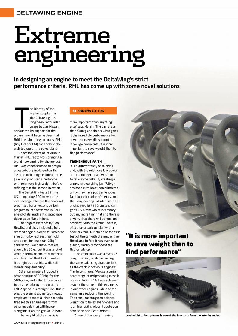
www.racecar-engineering.com • Le Mans
DELTAWING ENGINE
ExtremeengineeringIn designing an engine to meet the DeltaWing’s strict performance criteria, RML has come up with some novel solutions
“It is more important to save weight than to find performance”
T he identity of the engine supplier for the DeltaWing has long been kept under wraps but, as Nissan
announced its support for the programme, it became clear that British engineering company, RML (Ray Mallock Ltd), was behind the architecture of the powerplant.
Under the direction of Arnaud Martin, RML set to work creating a brand new engine for the project. RML was commissioned to design a bespoke engine based on the 1.6-litre turbo engine fitted to the Juke, and produced a prototype with relatively high weight, before refining it in the second iteration.
The DeltaWing tested in the US, completing 700km with the interim engine before the new unit was fitted for an extensive test programme at Snetterton in April, ahead of its much anticipated race debut at Le Mans in June.
‘The targets were set by Ben Bowlby, and they included a fully dressed engine, complete with heat shields, turbo, exhaust manifold and so on, for less than 95kg,’ said Martin. ‘We believe that we should hit 90kg, but it was a lot of work in terms of choice of material and design of the block to make it as light as possible, while still maintaining durability.’
Other parameters included a power output of 300bhp for the 500kg car, and a flat torque curve to be able to bring the car up to LMP2 speed in a straight line. But it was the weight saving techniques employed to meet all these criteria that set this engine apart from other models that will line up alongside it on the grid at Le Mans.
‘The weight of the chassis is
more important than anything else,’ says Martin. ‘The car is less than 500kg and that is what gives it the incredible performance for power, so every kilo you put on it, you go backwards. It is more important to save weight than to find performance.’
Tremendous faIThIt is a different way of thinking and, with the relatively low power output, the RML team was able to take some risks. By creating a crankshaft weighing just 7.8kg – achieved with holes bored into the unit – they have put tremendous faith in their choice of metals, and their engineering calculations. The engine revs to 7250rpm, and can go to 7500rpm where necessary, but any more than that and there is a worry that there will be torsional problems with the crank. There is, of course, a back-up plan with a heavier crank, but ahead of the first test of the car with the new engine fitted, and before it has even seen a dyno, Martin is confident the figures add up.
‘The crankshaft was a massive weight saving, whilst achieving the same balancing characteristic as the crank in previous engines,’ Martin continues. ‘We use a certain percentage of reciprocating mass in our calculations. We have achieved exactly the same in this engine as in our other engines, while at the same time reducing the weight. The crank has tungsten balance weight on it, holes everywhere and is an interesting piece. I doubt you have seen one like it before.
‘Some of the weight saving
by anDReW cotton
Low height carbon plenum is one of the few parts from the interim engine
REV22N6_DeltaWing Engine-acMP2 2.indd 54 28/05/2012 14:06
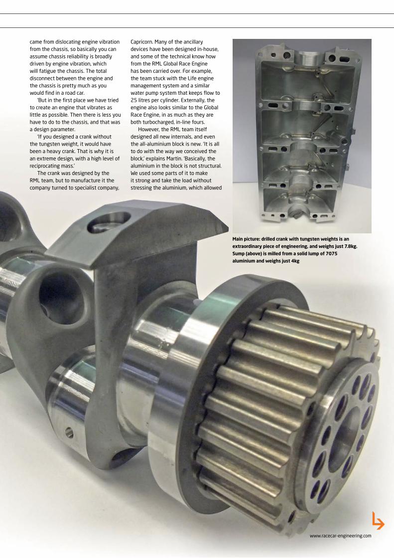
www.racecar-engineering.com
DELTAWING ENGINE
Main picture: drilled crank with tungsten weights is an
extraordinary piece of engineering, and weighs just 7.8kg.
Sump (above) is milled from a solid lump of 7075
aluminium and weighs just 4kg
came from dislocating engine vibration from the chassis, so basically you can assume chassis reliability is broadly driven by engine vibration, which will fatigue the chassis. The total disconnect between the engine and the chassis is pretty much as you would find in a road car.
‘But in the first place we have tried to create an engine that vibrates as little as possible. Then there is less you have to do to the chassis, and that was a design parameter.
‘If you designed a crank without the tungsten weight, it would have been a heavy crank. That is why it is an extreme design, with a high level of reciprocating mass.’
The crank was designed by the RML team, but to manufacture it the company turned to specialist company,
Capricorn. Many of the ancillary devices have been designed in-house, and some of the technical know how from the RML Global Race Engine has been carried over. For example, the team stuck with the Life engine management system and a similar water pump system that keeps flow to 25 litres per cylinder. Externally, the engine also looks similar to the Global Race Engine, in as much as they are both turbocharged, in-line fours.
However, the RML team itself designed all new internals, and even the all-aluminium block is new. ‘It is all to do with the way we conceived the block,’ explains Martin. ‘Basically, the aluminium in the block is not structural. We used some parts of it to make it strong and take the load without stressing the aluminium, which allowed
REV22N6_DeltaWing Engine-acMP2 2.indd 55 28/05/2012 14:06
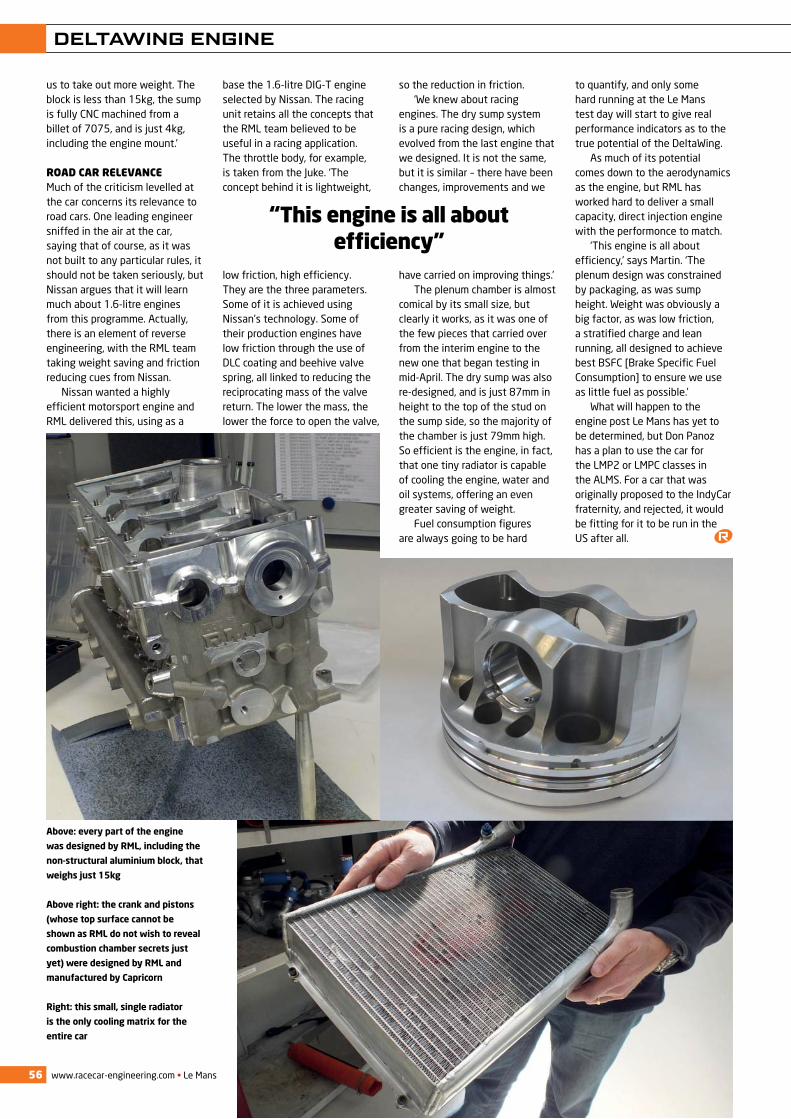
www.racecar-engineering.com • Le Mans
DELTAWING ENGINE
56
us to take out more weight. The block is less than 15kg, the sump is fully CNC machined from a billet of 7075, and is just 4kg, including the engine mount.’
road car relevanceMuch of the criticism levelled at the car concerns its relevance to road cars. One leading engineer sniffed in the air at the car, saying that of course, as it was not built to any particular rules, it should not be taken seriously, but Nissan argues that it will learn much about 1.6-litre engines from this programme. Actually, there is an element of reverse engineering, with the RML team taking weight saving and friction reducing cues from Nissan.
Nissan wanted a highly efficient motorsport engine and RML delivered this, using as a
base the 1.6-litre DIG-T engine selected by Nissan. The racing unit retains all the concepts that the RML team believed to be useful in a racing application. The throttle body, for example, is taken from the Juke. ‘The concept behind it is lightweight,
low friction, high efficiency. They are the three parameters. Some of it is achieved using Nissan’s technology. Some of their production engines have low friction through the use of DLC coating and beehive valve spring, all linked to reducing the reciprocating mass of the valve return. The lower the mass, the lower the force to open the valve,
so the reduction in friction.‘We knew about racing
engines. The dry sump system is a pure racing design, which evolved from the last engine that we designed. It is not the same, but it is similar – there have been changes, improvements and we
have carried on improving things.’The plenum chamber is almost
comical by its small size, but clearly it works, as it was one of the few pieces that carried over from the interim engine to the new one that began testing in mid-April. The dry sump was also re-designed, and is just 87mm in height to the top of the stud on the sump side, so the majority of the chamber is just 79mm high. So efficient is the engine, in fact, that one tiny radiator is capable of cooling the engine, water and oil systems, offering an even greater saving of weight.
Fuel consumption figures are always going to be hard
to quantify, and only some hard running at the Le Mans test day will start to give real performance indicators as to the true potential of the DeltaWing.
As much of its potential comes down to the aerodynamics as the engine, but RML has worked hard to deliver a small capacity, direct injection engine with the performonce to match.
‘This engine is all about efficiency,’ says Martin. ‘The plenum design was constrained by packaging, as was sump height. Weight was obviously a big factor, as was low friction, a stratified charge and lean running, all designed to achieve best BSFC [Brake Specific Fuel Consumption] to ensure we use as little fuel as possible.’
What will happen to the engine post Le Mans has yet to be determined, but Don Panoz has a plan to use the car for the LMP2 or LMPC classes in the ALMS. For a car that was originally proposed to the IndyCar fraternity, and rejected, it would be fitting for it to be run in the US after all.
Above: every part of the engine
was designed by RML, including the
non-structural aluminium block, that
weighs just 15kg
Above right: the crank and pistons
(whose top surface cannot be
shown as RML do not wish to reveal
combustion chamber secrets just
yet) were designed by RML and
manufactured by Capricorn
Right: this small, single radiator
is the only cooling matrix for the
entire car
“This engine is all about efficiency”
REV22N6_DeltaWing Engine-acMP2 2.indd 56 28/05/2012 14:07
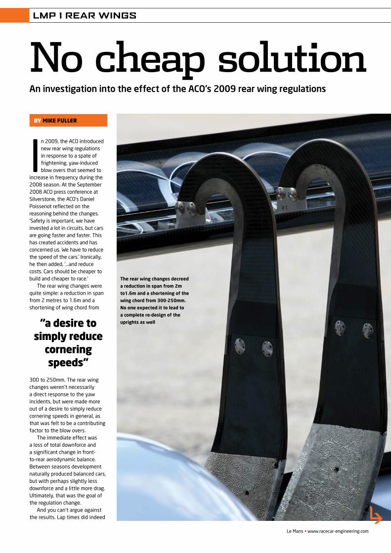
LMP 1 REAR WINGS
Le Mans • www.racecar-engineering.com
In 2009, the ACO introduced new rear wing regulations in response to a spate of frightening, yaw-induced blow overs that seemed to
increase in frequency during the 2008 season. At the September 2008 ACO press conference at Silverstone, the ACO’s Daniel Poissenot reflected on the reasoning behind the changes. ‘Safety is important, we have invested a lot in circuits, but cars are going faster and faster. This has created accidents and has concerned us. We have to reduce the speed of the cars.’ Ironically, he then added, ‘…and reduce costs. Cars should be cheaper to build and cheaper to race.’
The rear wing changes were quite simple: a reduction in span from 2 metres to 1.6m and a shortening of wing chord from
300 to 250mm. The rear wing changes weren’t necessarily a direct response to the yaw incidents, but were made more out of a desire to simply reduce cornering speeds in general, as that was felt to be a contributing factor to the blow overs.
The immediate effect was a loss of total downforce and a significant change in front-to-rear aerodynamic balance. Between seasons development naturally produced balanced cars, but with perhaps slightly less downforce and a little more drag. Ultimately, that was the goal of the regulation change.
And you can’t argue against the results. Lap times did indeed
An investigation into the effect of the ACO’s 2009 rear wing regulations
No cheap solutionby MIKE FULLER
“a desire to simply reduce
cornering speeds”
The rear wing changes decreed
a reduction in span from 2m
to1.6m and a shortening of the
wing chord from 300-250mm.
No one expected it to lead to
a complete re-design of the
uprights as well
REV22N1_LMP wings-MPAC.indd 73 21/05/2012 09:56
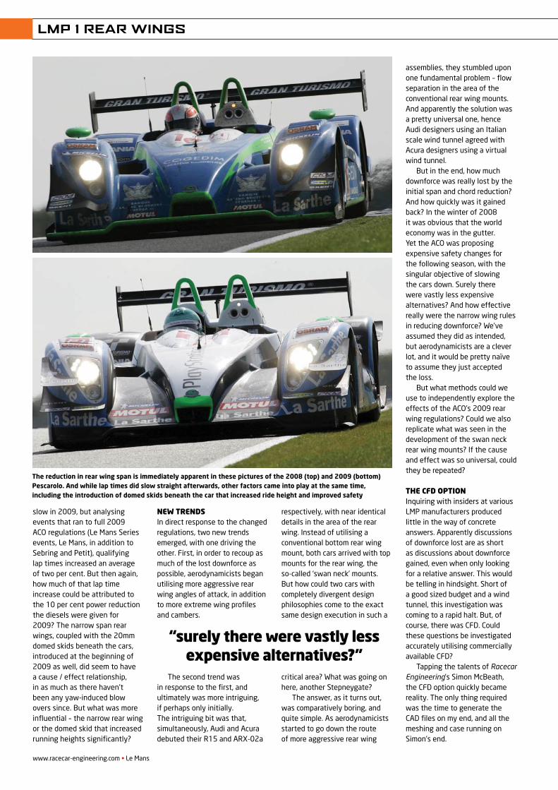
LMP 1 REAR WINGS
slow in 2009, but analysing events that ran to full 2009 ACO regulations (Le Mans Series events, Le Mans, in addition to Sebring and Petit), qualifying lap times increased an average of two per cent. But then again, how much of that lap time increase could be attributed to the 10 per cent power reduction the diesels were given for 2009? The narrow span rear wings, coupled with the 20mm domed skids beneath the cars, introduced at the beginning of 2009 as well, did seem to have a cause / effect relationship, in as much as there haven’t been any yaw-induced blow overs since. But what was more influential – the narrow rear wing or the domed skid that increased running heights significantly?
New treNdsIn direct response to the changed regulations, two new trends emerged, with one driving the other. First, in order to recoup as much of the lost downforce as possible, aerodynamicists began utilising more aggressive rear wing angles of attack, in addition to more extreme wing profiles and cambers.
The second trend was in response to the first, and ultimately was more intriguing, if perhaps only initially. The intriguing bit was that, simultaneously, Audi and Acura debuted their R15 and ARX-02a
respectively, with near identical details in the area of the rear wing. Instead of utilising a conventional bottom rear wing mount, both cars arrived with top mounts for the rear wing, the so-called ‘swan neck’ mounts. But how could two cars with completely divergent design philosophies come to the exact same design execution in such a
critical area? What was going on here, another Stepneygate?
The answer, as it turns out, was comparatively boring, and quite simple. As aerodynamicists started to go down the route of more aggressive rear wing
assemblies, they stumbled upon one fundamental problem – flow separation in the area of the conventional rear wing mounts. And apparently the solution was a pretty universal one, hence Audi designers using an Italian scale wind tunnel agreed with Acura designers using a virtual wind tunnel.
But in the end, how much downforce was really lost by the initial span and chord reduction? And how quickly was it gained back? In the winter of 2008 it was obvious that the world economy was in the gutter. Yet the ACO was proposing expensive safety changes for the following season, with the singular objective of slowing the cars down. Surely there were vastly less expensive alternatives? And how effective really were the narrow wing rules in reducing downforce? We’ve assumed they did as intended, but aerodynamicists are a clever lot, and it would be pretty naïve to assume they just accepted the loss.
But what methods could we use to independently explore the effects of the ACO’s 2009 rear wing regulations? Could we also replicate what was seen in the development of the swan neck rear wing mounts? If the cause and effect was so universal, could they be repeated?
the CFd optioNInquiring with insiders at various LMP manufacturers produced little in the way of concrete answers. Apparently discussions of downforce lost are as short as discussions about downforce gained, even when only looking for a relative answer. This would be telling in hindsight. Short of a good sized budget and a wind tunnel, this investigation was coming to a rapid halt. But, of course, there was CFD. Could these questions be investigated accurately utilising commercially available CFD?
Tapping the talents of Racecar Engineering’s Simon McBeath, the CFD option quickly became reality. The only thing required was the time to generate the CAD files on my end, and all the meshing and case running on Simon’s end.
www.racecar-engineering.com • Le Mans
“surely there were vastly less expensive alternatives?”
The reduction in rear wing span is immediately apparent in these pictures of the 2008 (top) and 2009 (bottom) Pescarolo. And while lap times did slow straight afterwards, other factors came into play at the same time, including the introduction of domed skids beneath the car that increased ride height and improved safety
REV22N1_LMP wings-MPAC.indd 74 21/05/2012 09:56
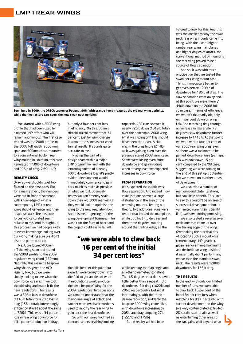
www.racecar-engineering.com • Le Mans
LMP 1 REAR WINGS
We started with a 2008 wing profile that had been used by a named LMP effort who will remain anonymous. The first case tested was the 2008 profile to the 2008 full width (2000mm) span and 300mm chord, mounted to a conventional bottom rear wing mount. In isolation, this case generated 1739lb of downforce and 226lb of drag, 7.69:1 L/D.
reality checkOkay, so we shouldn’t get too fixated on the absolutes. But, for a reality check, the numbers were put in front of someone with knowledge of what a contemporary LMP car rear wing should generate, and their response was: ‘The absolute forces you calculated seem reliable to me.’ And throughout this process we had people with relevant knowledge looking over our work, making sure we didn’t lose the plot too much.
Next, we lopped 400mm off the wing span and scaled the ‘2008’ profile to the 2009 regulated wing chord (250mm). Naturally, this wasn’t a bespoke wing shape, given the ACO legality box, but we were simply looking to see what the downforce loss was if we took the old wing and made it fit the new regulations. The results was a 593lb loss in downforce (1146lb total) for a 70lb loss in drag (156lb total). Interestingly, efficiency stayed about the same at 7.36:1. This was a 34 per cent loss in rear wing downforce for a 31 per cent reduction in drag,
but only a four per cent loss in efficiency. On this, Dome’s Hiroshi Yucchi commented: ‘34 per cent, just by wing change, is almost the same as our wind tunnel results. It sounds quite accurate to me.’
Playing the part of a design team within a major LMP programme, and with the ‘encouragement’ of a nearly 600lb downforce loss, it’s pretty evident development would immediately commence to gain back much as much as possible of what we lost. Obviously, teams wouldn’t merely scale down their old 2008 rear wings, they would look to optimise the wing to the new regulation box. And this meant getting into the wing development business. This wasn’t for the faint of heart and the project could easily fall off
the rails here. At this point our experts were brought back into the fold to get an idea of what manipulations would produce the best ‘bespoke’ wing for the 2009 regulations. In discussions, we came to understand that the mainplane angle of attack and camber were two basic methods used to modify the rear wing to gain back the lost downforce.
So with our wing modified as directed, and everything looking
copacetic, CFD runs showed it nearly 720lb down (1019lb total) over the benchmark 2008 wing. What was going on? This should have been the ticket. A clue was in the drag figure (214lb) as it was gaining even over the previous scaled 2008 wing case. So we were losing even more downforce and gaining drag when at very least we expected increases in downforce.
Flow separationWe suspected the culprit was flow separation. And indeed, flow visualisations showed a large disturbance in the area of the rear wing mounts. Testing our theory, two additional runs were tested that backed the mainplane angle out, first 1.5 degrees and then three degrees, rotating around the trailing edge, all the
while keeping the flap angle and all other parameters constant. The 1.5-degree reduction showed little better than a repeat: +3lb downforce, -8lb drag (1022lb and 206lb respectively). But most interestingly, with the three-degree reduction, suddenly the bespoke 2009 wing came alive, with downforce increasing by 205lb and drag dropping 27lb (1227lb and 179lb).
But in reality we had been
tutored to look for this. And this was the answer to why the swan neck rear wing mounts came into being. With the use of higher camber rear wing mainplanes and higher angles of attack, the conventional method of mounting the rear wing proved to be a source of flow separation.
And so, it was with much anticipation that we tested the swan neck wing mount case. Things immediately began to get even better: 1299lb of downforce for 186lb of drag. The flow separation went away and, at this point, we were ‘merely’ 440lb down on the 2008 full-span case. In terms of efficiency, we weren’t that badly off, only eight per cent down on wing L/D. And matching drag through an increase in flap angle (+8 degrees) saw downforce further increase to 1413lb. At that point, we were within four per cent of our 2008 rear wing drag level, so there was a tad more to be gained, downforce-wise (perhaps, L/D was now down 15 per cent compared to the ‘08 case, suggesting we were coming to the end of this set up’s potential), but we moved on to other areas of development.
We also tried a number of rear wing end plate iterations, but saw little benefit. This isn’t to say this couldn’t be an area of successful development but, in our limited running (all straight line), we saw nothing promising.
We also tested a reverse swan neck, one that came up over the trailing edge of the wing. Overlooking the practicalities of locating such a mount on a contemporary LMP gearbox, given rear overhang maximums and desired rear wing position, it essentially didn’t perform any worse than the standard swan neck. The results were 1288lb downforce, for 186lb drag.
the resultsIn the end, with only our limited number of runs, we were able to claw back 16 per cent of the initial 34 per cent loss when matching for drag. Certainly, with further development on the wing (we only contemplated extruded 2D sections, after all), as well as entertaining other areas of the car, gains well beyond what
“we were able to claw back 16 per cent of the initial
34 per cent loss”
Seen here in 2009, the ORECA customer Peugeot 908 (with orange livery) features the old rear wing uprights, while the two factory cars sport the new swan neck uprights
REV22N1_LMP wings-MPAC.indd 76 21/05/2012 09:56
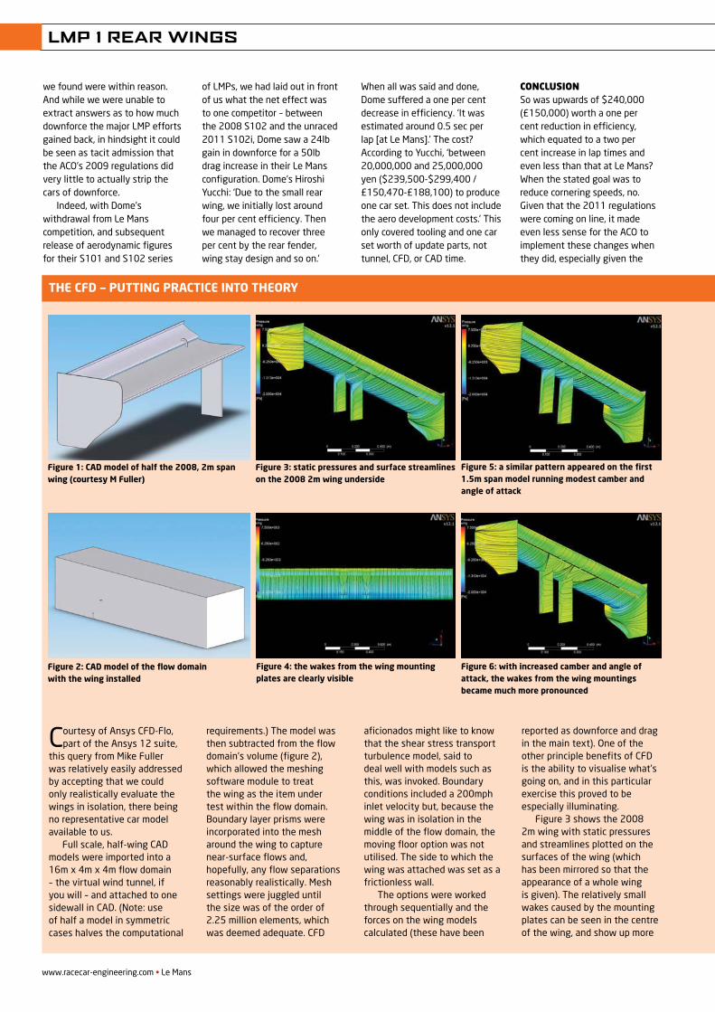
LMP 1 REAR WINGS
Courtesy of Ansys CFD-Flo, part of the Ansys 12 suite,
this query from Mike Fuller was relatively easily addressed by accepting that we could only realistically evaluate the wings in isolation, there being no representative car model available to us.
Full scale, half-wing CAD models were imported into a 16m x 4m x 4m flow domain – the virtual wind tunnel, if you will – and attached to one sidewall in CAD. (Note: use of half a model in symmetric cases halves the computational
requirements.) The model was then subtracted from the flow domain’s volume (figure 2), which allowed the meshing software module to treat the wing as the item under test within the flow domain. Boundary layer prisms were incorporated into the mesh around the wing to capture near-surface flows and, hopefully, any flow separations reasonably realistically. Mesh settings were juggled until the size was of the order of 2.25 million elements, which was deemed adequate. CFD
aficionados might like to know that the shear stress transport turbulence model, said to deal well with models such as this, was invoked. Boundary conditions included a 200mph inlet velocity but, because the wing was in isolation in the middle of the flow domain, the moving floor option was not utilised. The side to which the wing was attached was set as a frictionless wall.
The options were worked through sequentially and the forces on the wing models calculated (these have been
reported as downforce and drag in the main text). One of the other principle benefits of CFD is the ability to visualise what’s going on, and in this particular exercise this proved to be especially illuminating.
Figure 3 shows the 2008 2m wing with static pressures and streamlines plotted on the surfaces of the wing (which has been mirrored so that the appearance of a whole wing is given). The relatively small wakes caused by the mounting plates can be seen in the centre of the wing, and show up more
The CFD — PuTTing PraCTiCe inTo Theory
Figure 1: CaD model of half the 2008, 2m span wing (courtesy M Fuller)
Figure 2: CaD model of the flow domain with the wing installed
Figure 3: static pressures and surface streamlines on the 2008 2m wing underside
Figure 4: the wakes from the wing mounting plates are clearly visible
Figure 5: a similar pattern appeared on the first 1.5m span model running modest camber and angle of attack
Figure 6: with increased camber and angle of attack, the wakes from the wing mountings became much more pronounced
we found were within reason. And while we were unable to extract answers as to how much downforce the major LMP efforts gained back, in hindsight it could be seen as tacit admission that the ACO’s 2009 regulations did very little to actually strip the cars of downforce.
Indeed, with Dome’s withdrawal from Le Mans competition, and subsequent release of aerodynamic figures for their S101 and S102 series
of LMPs, we had laid out in front of us what the net effect was to one competitor – between the 2008 S102 and the unraced 2011 S102i, Dome saw a 24lb gain in downforce for a 50lb drag increase in their Le Mans configuration. Dome’s Hiroshi Yucchi: ‘Due to the small rear wing, we initially lost around four per cent efficiency. Then we managed to recover three per cent by the rear fender, wing stay design and so on.’
When all was said and done, Dome suffered a one per cent decrease in efficiency. ‘It was estimated around 0.5 sec per lap [at Le Mans].’ The cost? According to Yucchi, ‘between 20,000,000 and 25,000,000 yen ($239,500-$299,400 / £150,470-£188,100) to produce one car set. This does not include the aero development costs.’ This only covered tooling and one car set worth of update parts, not tunnel, CFD, or CAD time.
ConClusionSo was upwards of $240,000 (£150,000) worth a one per cent reduction in efficiency, which equated to a two per cent increase in lap times and even less than that at Le Mans? When the stated goal was to reduce cornering speeds, no. Given that the 2011 regulations were coming on line, it made even less sense for the ACO to implement these changes when they did, especially given the
www.racecar-engineering.com • Le Mans
REV22N1_LMP wings-MPAC.indd 78 21/05/2012 09:56
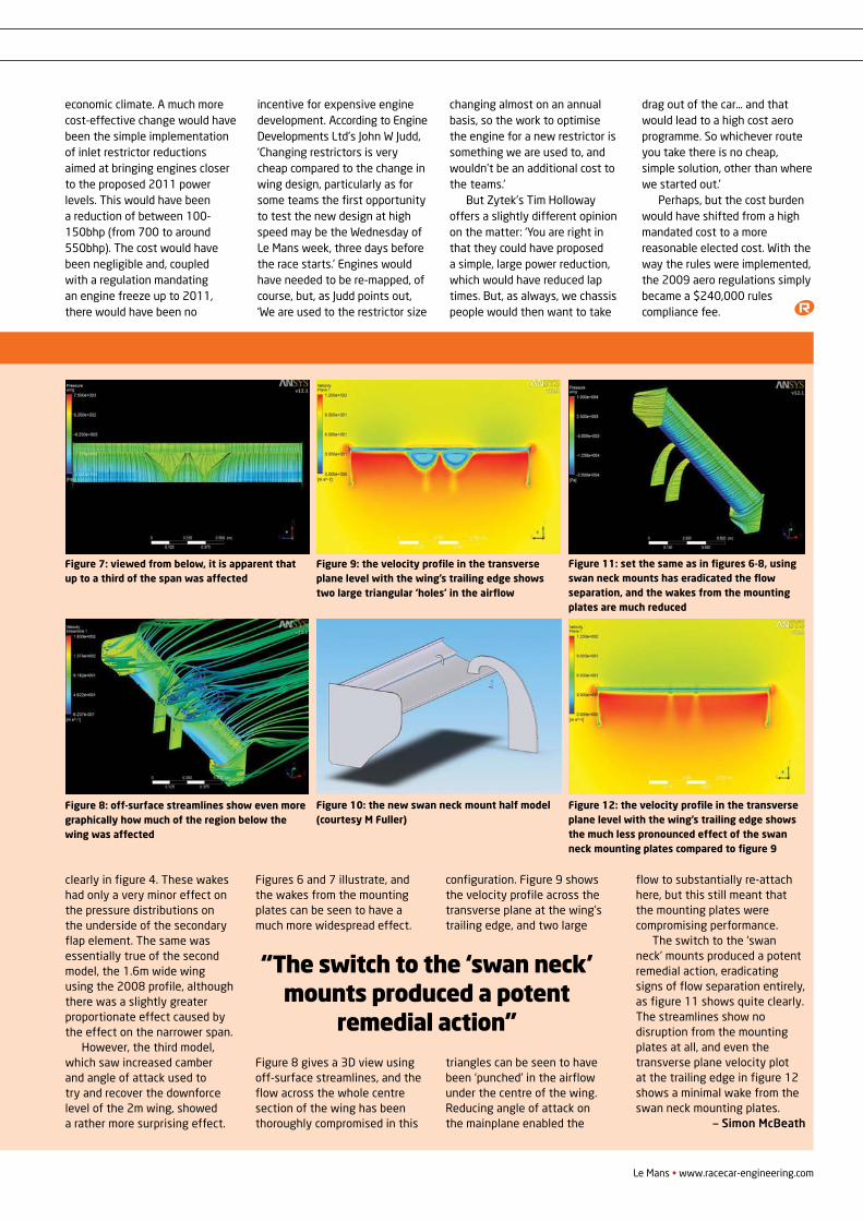
LMP 1 REAR WINGS
The CFD — PuTTing PraCTiCe inTo Theory
clearly in figure 4. These wakes had only a very minor effect on the pressure distributions on the underside of the secondary flap element. The same was essentially true of the second model, the 1.6m wide wing using the 2008 profile, although there was a slightly greater proportionate effect caused by the effect on the narrower span.
However, the third model, which saw increased camber and angle of attack used to try and recover the downforce level of the 2m wing, showed a rather more surprising effect.
Figures 6 and 7 illustrate, and the wakes from the mounting plates can be seen to have a much more widespread effect.
Figure 8 gives a 3D view using off-surface streamlines, and the flow across the whole centre section of the wing has been thoroughly compromised in this
configuration. Figure 9 shows the velocity profile across the transverse plane at the wing’s trailing edge, and two large
triangles can be seen to have been ‘punched’ in the airflow under the centre of the wing. Reducing angle of attack on the mainplane enabled the
flow to substantially re-attach here, but this still meant that the mounting plates were compromising performance.
The switch to the ‘swan neck’ mounts produced a potent remedial action, eradicating signs of flow separation entirely, as figure 11 shows quite clearly. The streamlines show no disruption from the mounting plates at all, and even the transverse plane velocity plot at the trailing edge in figure 12 shows a minimal wake from the swan neck mounting plates.
— Simon McBeath
Le Mans • www.racecar-engineering.com
“The switch to the ‘swan neck’ mounts produced a potent
remedial action”
Figure 7: viewed from below, it is apparent that up to a third of the span was affected
Figure 8: off-surface streamlines show even more graphically how much of the region below the wing was affected
Figure 9: the velocity profile in the transverse plane level with the wing’s trailing edge shows two large triangular ‘holes’ in the airflow
Figure 10: the new swan neck mount half model (courtesy M Fuller)
Figure 11: set the same as in figures 6-8, using swan neck mounts has eradicated the flow separation, and the wakes from the mounting plates are much reduced
Figure 12: the velocity profile in the transverse plane level with the wing’s trailing edge shows the much less pronounced effect of the swan neck mounting plates compared to figure 9
economic climate. A much more cost-effective change would have been the simple implementation of inlet restrictor reductions aimed at bringing engines closer to the proposed 2011 power levels. This would have been a reduction of between 100-150bhp (from 700 to around 550bhp). The cost would have been negligible and, coupled with a regulation mandating an engine freeze up to 2011, there would have been no
incentive for expensive engine development. According to Engine Developments Ltd’s John W Judd, ‘Changing restrictors is very cheap compared to the change in wing design, particularly as for some teams the first opportunity to test the new design at high speed may be the Wednesday of Le Mans week, three days before the race starts.’ Engines would have needed to be re-mapped, of course, but, as Judd points out, ‘We are used to the restrictor size
changing almost on an annual basis, so the work to optimise the engine for a new restrictor is something we are used to, and wouldn’t be an additional cost to the teams.’
But Zytek’s Tim Holloway offers a slightly different opinion on the matter: ‘You are right in that they could have proposed a simple, large power reduction, which would have reduced lap times. But, as always, we chassis people would then want to take
drag out of the car… and that would lead to a high cost aero programme. So whichever route you take there is no cheap, simple solution, other than where we started out.’
Perhaps, but the cost burden would have shifted from a high mandated cost to a more reasonable elected cost. With the way the rules were implemented, the 2009 aero regulations simply became a $240,000 rules compliance fee.
REV22N1_LMP wings-MPAC.indd 79 21/05/2012 09:57
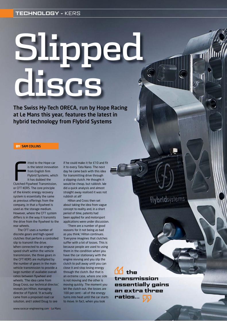
The Swiss Hy-Tech ORECA, run by Hope Racing at Le Mans this year, features the latest in hybrid technology from Flybrid Systems
Slipped discs
Fitted to the Hope car is the latest innovation from English fi rm Flybrid Systems, which it has dubbed the
Clutched Flywheel Transmission, or CFT KERS. The core principle of the kinetic energy recovery system is essentially the same as previous offerings from the company, in that a fl ywheel is used as the storage medium. However, where the CFT system differs is in the way it transmits the drive from the fl ywheel to the rear wheels.
The CFT uses a number of discrete gears and high-speed clutches that perform a controlled slip to transmit the drive. When connected to an engine-speed shaft within the vehicle transmission, the three gears in the CFT KERS are multiplied by the number of gears in the main vehicle transmission to provide a large number of available overall ratios between fl ywheel and wheels. ‘The idea came from Doug Cross, our technical director,’ reveals Jon Hilton, managing director of Flybrid. ‘It actually came from a proposed road car solution, and I asked Doug to see
if he could make it for £10 and fi t it to every Tata Nano. The next day he came back with this idea for transmitting drive through a slipping clutch. He thought it would be cheap, but rubbish. We did a quick analysis and almost straight away realised it was not rubbish at all!’
Hilton and Cross then set about taking the idea from vague concept to reality and, in a short period of time, patents had been applied for and motorsport applications were under discussion.
‘There are a number of good reasons for it not being as bad as you think,’ Hilton continues. ‘Everyone imagines that clutches suffer with a lot of losses. This is because people are used to using them in the condition when you have the car stationary with the engine revving and you slip the clutch to pull away until you can close it and stop losing energy through the clutch. But that is an extreme case, where one side is not moving and the other is moving quickly. The moment you let the clutch out, the losses are 100 per cent – all of the energy turns into heat until the car starts to move. In fact, when you look
the transmission essentially gains an extra three ratios…
BY SAM COLLINS
www.racecar-engineering.com • Le Mans
TECHNOLOGY - KERS
REV21N7_Flybrid-MPAC.indd 48 21/05/2012 09:58
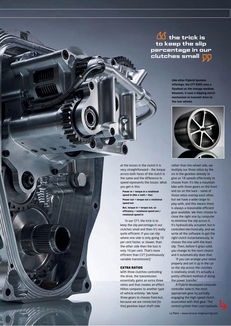
Le Mans • www.racecar-engineering.com
the trick is to keep the slip
percentage in our clutches small
at the losses in the clutch it is very straightforward – the torque across both faces of the clutch is the same and the difference in speed represents the losses. What you get is this:
Power in = torque in x rotational speed in (Nm x rad/s = Kw)
Power out = torque out x rotational speed out
But, torque in = torque out, so effi ciency = rotational speed out / rotational speed in
‘In our CFT, the trick is to keep the slip percentage in our clutches small and then it’s really quite effi cient. If you can slip where one side is only going 10 per cent faster, or slower, than the other side then the loss is only 10 per cent. That’s more effi cient than CVT [continuously variable transmission].’
EXTRA RATIOSWith three clutches controlling the drive, the transmission essentially gains an extra three ratios and that creates an effect Hilton compares to another type of vehicle entirely: ‘We have three gears to choose from but, because we are connected [to the] gearbox input shaft side
rather than the wheel side, we multiply our three ratios by the six in the gearbox already to give us 18 speeds effectively to choose from. It’s like a mountain bike with three gears on the front and six on the back – some of those ratios overlap each other, but we have a wide range to play with, and this means there is always a reasonable effi cient gear available. We then choose to close the right one by computer to minimise the slip across it. It’s hydraulically actuated, but is controlled electronically, and we write all the software to get the right clutch instantaneously, to choose the one with the least slip. Then, before it grips solid, you change to the next closest and it automatically does that.
‘If you can arrange your ratios properly and set it up in the car so the slip across the clutches is relatively small, it’s actually a pretty effi cient method of doing the power transfer.’
A Flybrid-developed computer controller selects the most appropriate gear by partially engaging the high-speed clutch associated with that gear. The control system then uses hydraulic
Like other Flybrid Systems
offerings, the CFT KERS uses a
fl ywheel as the storage medium.
However, it uses a slipping clutch
mechanism to transmit drive to
the rear wheels
TECHNOLOGY - KERS
REV21N7_Flybrid-MPAC.indd 49 21/05/2012 09:59
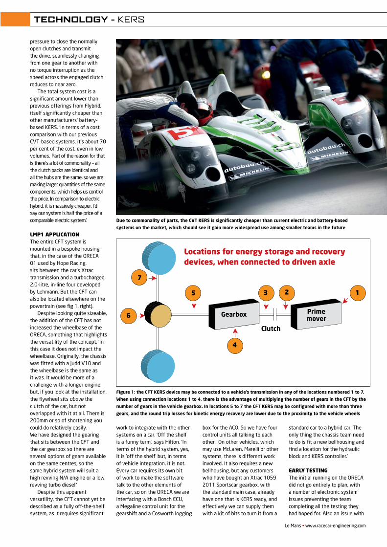
Le Mans • www.racecar-engineering.com
pressure to close the normally open clutches and transmit the drive, seamlessly changing from one gear to another with no torque interruption as the speed across the engaged clutch reduces to near zero.
The total system cost is a significant amount lower than previous offerings from Flybrid, itself significantly cheaper than other manufacturers’ battery-based KERS. ‘In terms of a cost comparison with our previous CVT-based systems, it’s about 70 per cent of the cost, even in low volumes. Part of the reason for that is there’s a lot of commonality – all the clutch packs are identical and all the hubs are the same, so we are making larger quantities of the same components, which helps us control the price. In comparison to electric hybrid, it is massively cheaper. I’d say our system is half the price of a comparable electric system.’
LMP1 aPPLicationThe entire CFT system is mounted in a bespoke housing that, in the case of the ORECA 01 used by Hope Racing, sits between the car’s Xtrac transmission and a turbocharged, 2.0-litre, in-line four developed by Lehmann. But the CFT can also be located elsewhere on the powertrain (see fig 1, right).
Despite looking quite sizeable, the addition of the CFT has not increased the wheelbase of the ORECA, something that highlights the versatility of the concept. ‘In this case it does not impact the wheelbase. Originally, the chassis was fitted with a Judd V10 and the wheelbase is the same as it was. It would be more of a challenge with a longer engine but, if you look at the installation, the flywheel sits above the clutch of the car, but not overlapped with it at all. There is 200mm or so of shortening you could do relatively easily. We have designed the gearing that sits between the CFT and the car gearbox so there are several options of gears available on the same centres, so the same hybrid system will suit a high revving N/A engine or a low revving turbo diesel.’
Despite this apparent versatility, the CFT cannot yet be described as a fully off-the-shelf system, as it requires significant
work to integrate with the other systems on a car. ‘Off the shelf is a funny term,’ says Hilton. ‘In terms of the hybrid system, yes, it is ‘off the shelf’ but, in terms of vehicle integration, it is not. Every car requires its own bit of work to make the software talk to the other elements of the car, so on the ORECA we are interfacing with a Bosch ECU, a Megaline control unit for the gearshift and a Cosworth logging
box for the ACO. So we have four control units all talking to each other. On other vehicles, which may use McLaren, Marelli or other systems, there is different work involved. It also requires a new bellhousing, but any customers who have bought an Xtrac 1059 2011 Sportscar gearbox, with the standard main case, already have one that is KERS ready, and effectively we can supply them with a kit of bits to turn it from a
standard car to a hybrid car. The only thing the chassis team need to do is fit a new bellhousing and find a location for the hydraulic block and KERS controller.’
EarLy tEstingThe initial running on the ORECA did not go entirely to plan, with a number of electronic system issues preventing the team completing all the testing they had hoped for. Also an issue with
Due to commonality of parts, the CVT KERS is significantly cheaper than current electric and battery-based
systems on the market, which should see it gain more widespread use among smaller teams in the future
Figure 1: the CFT KERS device may be connected to a vehicle’s transmission in any of the locations numbered 1 to 7.
When using connection locations 1 to 4, there is the advantage of multiplying the number of gears in the CFT by the
number of gears in the vehicle gearbox. In locations 5 to 7 the CFT KERS may be configured with more than three
gears, and the round trip losses for kinetic energy recovery are lower due to the proximity to the vehicle wheels
Locations for energy storage and recovery devices, when connected to driven axle
7
6
5
4
3 2 1
Gearbox Prime mover
Clutch
TECHNOLOGY - KERS
REV21N7_Flybrid-MPAC.indd 51 21/05/2012 09:59
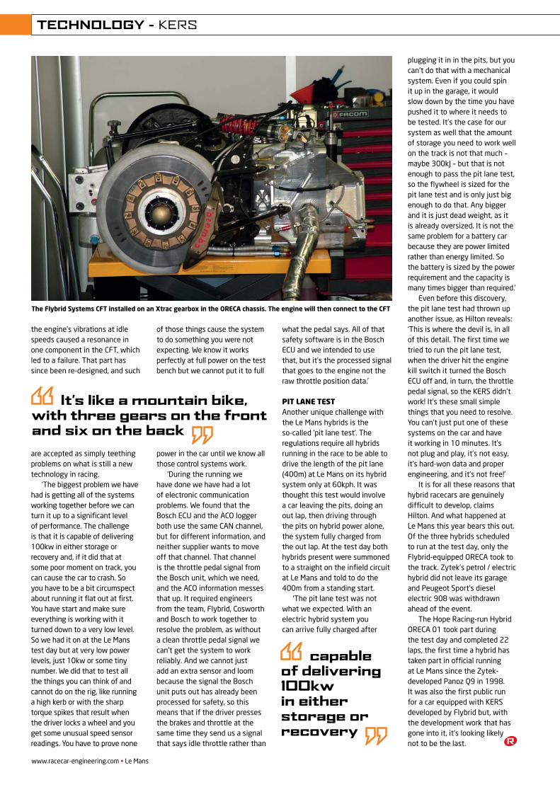
www.racecar-engineering.com • Le Mans
TECHNOLOGY - KERS
52
the engine’s vibrations at idle speeds caused a resonance in one component in the CFT, which led to a failure. That part has since been re-designed, and such
are accepted as simply teething problems on what is still a new technology in racing.
‘The biggest problem we have had is getting all of the systems working together before we can turn it up to a significant level of performance. The challenge is that it is capable of delivering 100kw in either storage or recovery and, if it did that at some poor moment on track, you can cause the car to crash. So you have to be a bit circumspect about running it flat out at first. You have start and make sure everything is working with it turned down to a very low level. So we had it on at the Le Mans test day but at very low power levels, just 10kw or some tiny number. We did that to test all the things you can think of and cannot do on the rig, like running a high kerb or with the sharp torque spikes that result when the driver locks a wheel and you get some unusual speed sensor readings. You have to prove none
of those things cause the system to do something you were not expecting. We know it works perfectly at full power on the test bench but we cannot put it to full
power in the car until we know all those control systems work.
‘During the running we have done we have had a lot of electronic communication problems. We found that the Bosch ECU and the ACO logger both use the same CAN channel, but for different information, and neither supplier wants to move off that channel. That channel is the throttle pedal signal from the Bosch unit, which we need, and the ACO information messes that up. It required engineers from the team, Flybrid, Cosworth and Bosch to work together to resolve the problem, as without a clean throttle pedal signal we can’t get the system to work reliably. And we cannot just add an extra sensor and loom because the signal the Bosch unit puts out has already been processed for safety, so this means that if the driver presses the brakes and throttle at the same time they send us a signal that says idle throttle rather than
what the pedal says. All of that safety software is in the Bosch ECU and we intended to use that, but it’s the processed signal that goes to the engine not the raw throttle position data.’
Pit lane testAnother unique challenge with the Le Mans hybrids is the so-called ‘pit lane test’. The regulations require all hybrids running in the race to be able to drive the length of the pit lane (400m) at Le Mans on its hybrid system only at 60kph. It was thought this test would involve a car leaving the pits, doing an out lap, then driving through the pits on hybrid power alone, the system fully charged from the out lap. At the test day both hybrids present were summoned to a straight on the infield circuit at Le Mans and told to do the 400m from a standing start.
‘The pit lane test was not what we expected. With an electric hybrid system you can arrive fully charged after
plugging it in in the pits, but you can’t do that with a mechanical system. Even if you could spin it up in the garage, it would slow down by the time you have pushed it to where it needs to be tested. It’s the case for our system as well that the amount of storage you need to work well on the track is not that much – maybe 300kJ – but that is not enough to pass the pit lane test, so the flywheel is sized for the pit lane test and is only just big enough to do that. Any bigger and it is just dead weight, as it is already oversized. It is not the same problem for a battery car because they are power limited rather than energy limited. So the battery is sized by the power requirement and the capacity is many times bigger than required.’
Even before this discovery, the pit lane test had thrown up another issue, as Hilton reveals: ‘This is where the devil is, in all of this detail. The first time we tried to run the pit lane test, when the driver hit the engine kill switch it turned the Bosch ECU off and, in turn, the throttle pedal signal, so the KERS didn’t work! It’s these small simple things that you need to resolve. You can’t just put one of these systems on the car and have it working in 10 minutes. It’s not plug and play, it’s not easy, it’s hard-won data and proper engineering, and it’s not free!’
It is for all these reasons that hybrid racecars are genuinely difficult to develop, claims Hilton. And what happened at Le Mans this year bears this out. Of the three hybrids scheduled to run at the test day, only the Flybrid-equipped ORECA took to the track. Zytek’s petrol / electric hybrid did not leave its garage and Peugeot Sport’s diesel electric 908 was withdrawn ahead of the event.
The Hope Racing-run Hybrid ORECA 01 took part during the test day and completed 22 laps, the first time a hybrid has taken part in official running at Le Mans since the Zytek-developed Panoz Q9 in 1998. It was also the first public run for a car equipped with KERS developed by Flybrid but, with the development work that has gone into it, it’s looking likely not to be the last.
The Flybrid Systems CFT installed on an Xtrac gearbox in the ORECA chassis. The engine will then connect to the CFT
It’s like a mountain bike, with three gears on the front and six on the back
capable of delivering 100kw in either storage or recovery
REV21N7_Flybrid-MPAC.indd 52 21/05/2012 09:59

Untitled-3 1 02/05/2012 18:12
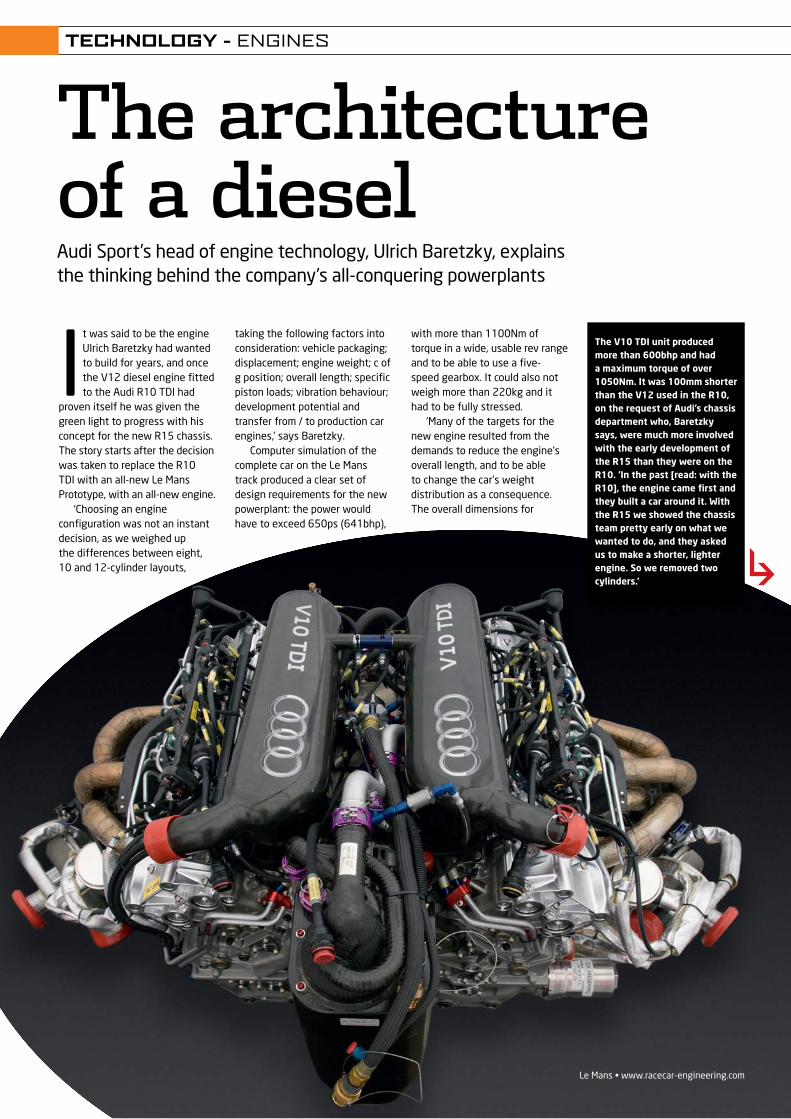
Le Mans • www.racecar-engineering.com
It was said to be the engine Ulrich Baretzky had wanted to build for years, and once the V12 diesel engine fitted to the Audi R10 TDI had
proven itself he was given the green light to progress with his concept for the new R15 chassis. The story starts after the decision was taken to replace the R10 TDI with an all-new Le Mans Prototype, with an all-new engine.
‘Choosing an engine configuration was not an instant decision, as we weighed up the differences between eight, 10 and 12-cylinder layouts,
The architecture of a dieselAudi Sport’s head of engine technology, Ulrich Baretzky, explains the thinking behind the company’s all-conquering powerplants
taking the following factors into consideration: vehicle packaging; displacement; engine weight; c of g position; overall length; specific piston loads; vibration behaviour; development potential and transfer from / to production car engines,’ says Baretzky.
Computer simulation of the complete car on the Le Mans track produced a clear set of design requirements for the new powerplant: the power would have to exceed 650ps (641bhp),
with more than 1100Nm of torque in a wide, usable rev range and to be able to use a five-speed gearbox. It could also not weigh more than 220kg and it had to be fully stressed.
‘Many of the targets for the new engine resulted from the demands to reduce the engine’s overall length, and to be able to change the car’s weight distribution as a consequence. The overall dimensions for
The V10 TDI unit produced more than 600bhp and had a maximum torque of over 1050Nm. It was 100mm shorter than the V12 used in the R10, on the request of Audi’s chassis department who, Baretzky says, were much more involved with the early development of the R15 than they were on the R10. ‘In the past [read: with the R10], the engine came first and they built a car around it. With the R15 we showed the chassis team pretty early on what we wanted to do, and they asked us to make a shorter, lighter engine. So we removed two cylinders.’
TECHNOLOGY - ENGINES
REV21N7_Diesel-MPAC.indd 41 21/05/2012 10:00
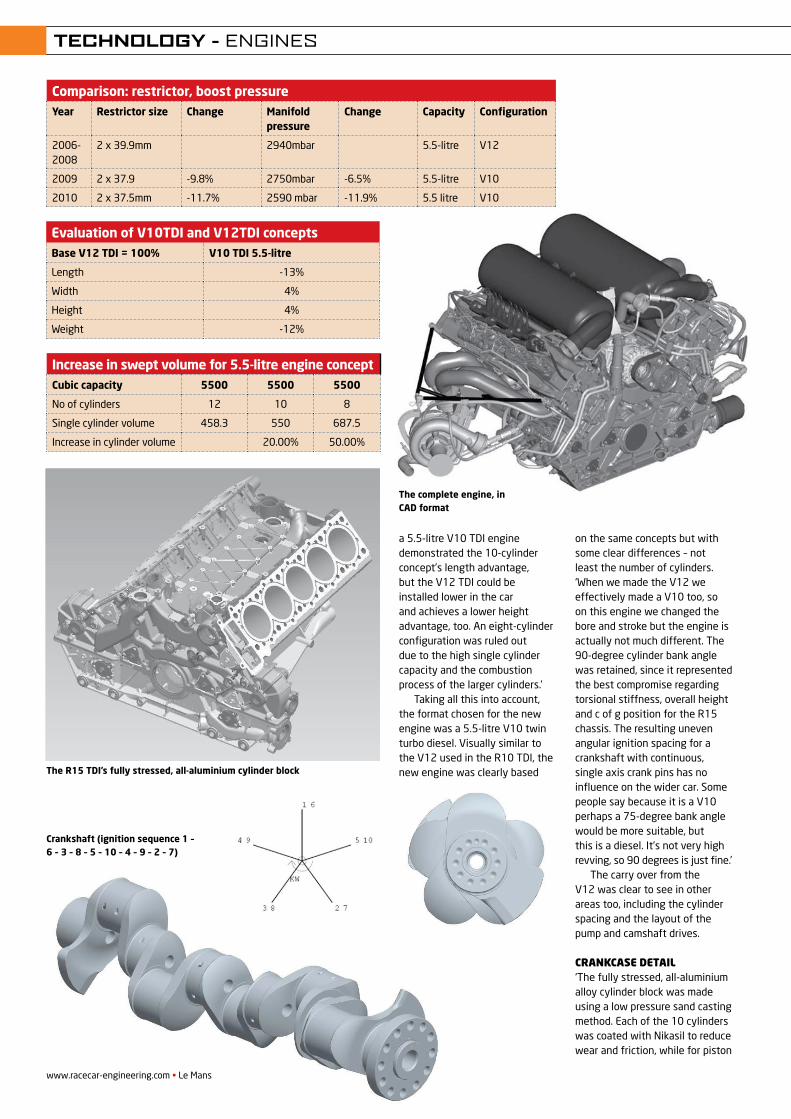
a 5.5-litre V10 TDI engine demonstrated the 10-cylinder concept’s length advantage, but the V12 TDI could be installed lower in the car and achieves a lower height advantage, too. An eight-cylinder configuration was ruled out due to the high single cylinder capacity and the combustion process of the larger cylinders.’
Taking all this into account, the format chosen for the new engine was a 5.5-litre V10 twin turbo diesel. Visually similar to the V12 used in the R10 TDI, the new engine was clearly based
on the same concepts but with some clear differences – not least the number of cylinders. ‘When we made the V12 we effectively made a V10 too, so on this engine we changed the bore and stroke but the engine is actually not much different. The 90-degree cylinder bank angle was retained, since it represented the best compromise regarding torsional stiffness, overall height and c of g position for the R15 chassis. The resulting uneven angular ignition spacing for a crankshaft with continuous, single axis crank pins has no influence on the wider car. Some people say because it is a V10 perhaps a 75-degree bank angle would be more suitable, but this is a diesel. It’s not very high revving, so 90 degrees is just fine.’
The carry over from the V12 was clear to see in other areas too, including the cylinder spacing and the layout of the pump and camshaft drives.
crankcase detail‘The fully stressed, all-aluminium alloy cylinder block was made using a low pressure sand casting method. Each of the 10 cylinders was coated with Nikasil to reduce wear and friction, while for piston
- 11 -
The crankcase below the main bearing centre line is manufactured identical to the R10 as complex, heavy-duty cast component – the so-called bedplate. Owing to directional solidification (Sophia® process) the precision casting has equally high strength (Rm 35 Mpa) and ductility. The minimum wall thickness is less than 2 mm. The dry sump‟s side mounted scavenge port and ribbings connect the bearing blocks with one another. A very stiff unit is created together with the upper crankcase part. Engine and monocoque have thus almost the same stiffness. The main bearings are fastened with two bolts on each side. The four lower engine mounting/monocoque studs are connected to the gear wheel shaft and are braced by stiffeners to the main bearings. 4.2 Crankshaft drive Owing to its design and construction as 10-cylinder, the crankshaft drive is subject to an unbalanced momentum. The crankshaft‟s design considers several aspects: Bearing load through maximum ignition pressure, inertial forces Unbalanced momentums of the 1st and 2nd order Torsion and bending stiffness Minimum weight
Picture 10: Crankshaft (ignition sequence 1 – 6 – 3 – 8 – 5 – 10 – 4 – 9 – 2 – 7) Even without compensating masses the moments of the first order acting towards the outside for the selected cranking layout are minimal. The moments of the second order are limited to a tolerable degree for a race car.
www.racecar-engineering.com • Le Mans
Comparison: restrictor, boost pressureYear Restrictor size Change Manifold
pressureChange Capacity Configuration
2006-2008
2 x 39.9mm 2940mbar 5.5-litre V12
2009 2 x 37.9 -9.8% 2750mbar -6.5% 5.5-litre V10
2010 2 x 37.5mm -11.7% 2590 mbar -11.9% 5.5 litre V10
Evaluation of V10TDI and V12TDI conceptsBase V12 TDI = 100% V10 TDI 5.5-litre
Length -13%
Width 4%
Height 4%
Weight -12%
Increase in swept volume for 5.5-litre engine conceptCubic capacity 5500 5500 5500
No of cylinders 12 10 8
Single cylinder volume 458.3 550 687.5
Increase in cylinder volume 20.00% 50.00%
- 9 -
Figure 7: Development process of R15 V10TDI engine development 4. Engine design The engine was designed with the following targets in mind: Compact dimensions High engine stiffness for low weight Very high mechanical durability High level of component integration Low number of exterior fittings and connectors
Figure 8: Complete engine
The complete engine, in CAD format
- 10 -
The 90 degree cylinder bank angle was retained, since it represented the best compromise regarding torsional stiffness, overall height and centre of gravity position for this car. The resulting uneven angular ignition spacing for a crankshaft with continuous, single axis crank pins has no influence in the race car The engine‟s installation height is influenced significantly by the stroke. Although the stroke was increased by 9%, the distance between the crankshaft centre-line and the base plate was reduced to by 4%. As a result the Audi engine has an extremely low installation height and a correspondingly low centre of gravity. The experience gathered in racing diesel-engine development is also reflected in this. Every peripheral component was optimised with regard to modular design and quick exchange. 4.1 Engine block and bed plate The cylinder block (closed deck) is manufactured from an aluminium alloy casting using the low-pressure sand casting method. The cylinders are Nikasil® coated. For piston cooling purposes corresponding oil grooves with cut-off control valves are integrated in the block. The integral cast water channels with junction to the heat-exchanger have only the connection to the water coolers in otherwise closed water circuits. Pressure and temperature sensor monitor the oil and water circuits.
Picture 9: R15 TDI cylinder block
The R15 TDI’s fully stressed, all-aluminium cylinder block
Crankshaft (ignition sequence 1 – 6 – 3 – 8 – 5 – 10 – 4 – 9 – 2 – 7)
TECHNOLOGY - ENGINES
REV21N7_Diesel-MPAC.indd 42 21/05/2012 10:01
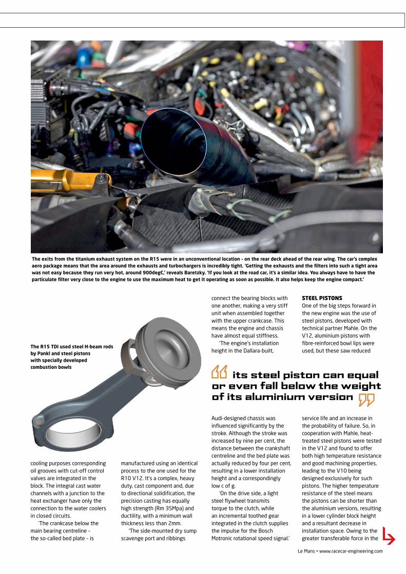
cooling purposes corresponding oil grooves with cut-off control valves are integrated in the block. The integral cast water channels with a junction to the heat exchanger have only the connection to the water coolers in closed circuits.
‘The crankcase below the main bearing centreline – the so-called bed plate – is
manufactured using an identical process to the one used for the R10 V12. It’s a complex, heavy duty, cast component and, due to directional solidification, the precision casting has equally high strength (Rm 35Mpa) and ductility, with a minimum wall thickness less than 2mm.
‘The side-mounted dry sump scavenge port and ribbings
connect the bearing blocks with one another, making a very stiff unit when assembled together with the upper crankcase. This means the engine and chassis have almost equal stiffness.
‘The engine’s installation height in the Dallara-built,
Audi-designed chassis was influenced significantly by the stroke. Although the stroke was increased by nine per cent, the distance between the crankshaft centreline and the bed plate was actually reduced by four per cent, resulting in a lower installation height and a correspondingly low c of g.
‘On the drive side, a light steel flywheel transmits torque to the clutch, while an incremental toothed gear integrated in the clutch supplies the impulse for the Bosch Motronic rotational speed signal.’
Steel piStonSOne of the big steps forward in the new engine was the use of steel pistons, developed with technical partner Mahle. On the V12, aluminium pistons with fibre-reinforced bowl lips were used, but these saw reduced
service life and an increase in the probability of failure. So, in cooperation with Mahle, heat-treated steel pistons were tested in the V12 and found to offer both high temperature resistance and good machining properties, leading to the V10 being designed exclusively for such pistons. The higher temperature resistance of the steel means the pistons can be shorter than the aluminium versions, resulting in a lower cylinder block height and a resultant decrease in installation space. Owing to the greater transferable force in the
Le Mans • www.racecar-engineering.com
- 12 -
The essential crankshaft dimensions were defined using bearing load and hydrodynamic lubrication gap calculations in conjunction with FEM. In this way the diameter and width of the main and connecting rod bearings were defined according to operational demands and the crankshaft webs also determined for greater stiffness of the journal connection. The counterweights were optimised for the rev range and load spectrum. A vibration damper could therefore be omitted. On the drive-side a light steel-flywheel transmits torque to the clutch. An incremental toothed gear integrated in the clutch supplies the impulse for the Bosch Motronik rotational speed signal. Another incremental toothed gear in front of the camshaft gear drive is a redundancy in the rotational speed recognition. The obliquely divided steel connecting rod is manufactured from H profile like the R10 and was optimised with regard to stiffness and minimum weight by FEM calculation.
Picture 11: R15 TDI connecting rod and piston The Mahle steel piston has a combustion bowl developed specifically for this use. The high thermal loads made using two piston spray nozzles necessary. One spray nozzle is for the piston base the other for to supply the cooling channel. 4.3 Piston The piston is manufactured from heat-treatable steel. This material combines the properties of high temperature resistance and good machining properties. In addition to the higher temperature resistance the steel piston has the advantage that the top-land is shorter than an aluminium piston‟s [7]. Owing to the greater transferable force in the pin bore the gudgeon pin fitted to the steel piston can be considerably shorter thus allowing a lighter component. All told, the piston can equal or even fall below the weight of its aluminium counterpart.
The R15 TDI used steel H-beam rods by Pankl and steel pistonswith specially developedcombustion bowls
its steel piston can equal or even fall below the weight of its aluminium version
The exits from the titanium exhaust system on the R15 were in an unconventional location – on the rear deck ahead of the rear wing. The car’s complex aero package means that the area around the exhausts and turbochargers is incredibly tight. ‘Getting the exhausts and the filters into such a tight area was not easy because they run very hot, around 900degC,’ reveals Baretzky. ‘If you look at the road car, it’s a similar idea. You always have to have the particulate filter very close to the engine to use the maximum heat to get it operating as soon as possible. It also helps keep the engine compact.’
TECHNOLOGY - ENGINES
REV21N7_Diesel-MPAC.indd 43 21/05/2012 10:01
We provide engineering, construction, operations, and maintenance services for the motorsport community’s most complex testing, research, and development facilities. To date, we have developed facilities for motorsport testing applications in Europe, Asia, and North America. Our wind tunnel experience spans the full spectrum of configurations: solid wall, open jet, slotted wall, and adaptive wall.
The latest release of our automated test measurement and control software, Test SLATE, offers a proven solution for integrating diverse hardware and subsystems, managing test configurations, and transforming test data into meaningful results.
We offer unique consulting services ranging from test planning to high powered computer simulation. We provide aerodynamic/flow analysis, stress and thermal analysis, acoustic analysis, and more to motorsport teams.
Please contact us to learn how we can support you!
Untitled-19 1 29/02/2012 15:50
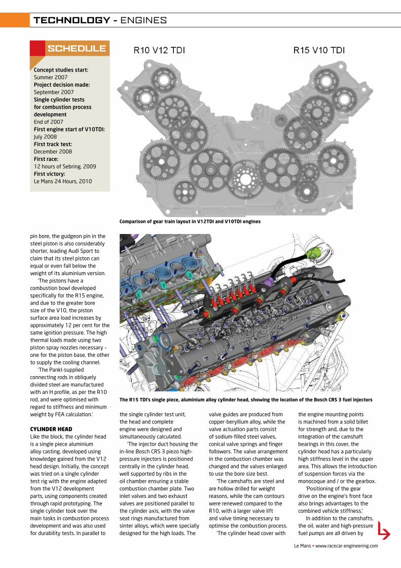
pin bore, the gudgeon pin in the steel piston is also considerably shorter, leading Audi Sport to claim that its steel piston can equal or even fall below the weight of its aluminium version.
‘The pistons have a combustion bowl developed specifically for the R15 engine, and due to the greater bore size of the V10, the piston surface area load increases by approximately 12 per cent for the same ignition pressure. The high thermal loads made using two piston spray nozzles necessary – one for the piston base, the other to supply the cooling channel.
‘The Pankl-supplied connecting rods in obliquely divided steel are manufactured with an H profile, as per the R10 rod, and were optimised with regard to stiffness and minimum weight by FEA calculation.’
Cylinder headLike the block, the cylinder head is a single piece aluminium alloy casting, developed using knowledge gained from the V12 head design. Initially, the concept was tried on a single cylinder test rig with the engine adapted from the V12 development parts, using components created through rapid prototyping. The single cylinder took over the main tasks in combustion process development and was also used for durability tests. In parallel to
the single cylinder test unit, the head and complete engine were designed and simultaneously calculated.
‘The injector duct housing the in-line Bosch CRS 3 piezo high-pressure injectors is positioned centrally in the cylinder head, well supported by ribs in the oil chamber ensuring a stable combustion chamber plate. Two inlet valves and two exhaust valves are positioned parallel to the cylinder axis, with the valve seat rings manufactured from sinter alloys, which were specially designed for the high loads. The
valve guides are produced from copper-beryllium alloy, while the valve actuation parts consist of sodium-filled steel valves, conical valve springs and finger followers. The valve arrangement in the combustion chamber was changed and the valves enlarged to use the bore size best.
‘The camshafts are steel and are hollow drilled for weight reasons, while the cam contours were renewed compared to the R10, with a larger valve lift and valve timing necessary to optimise the combustion process.
‘The cylinder head cover with
the engine mounting points is machined from a solid billet for strength and, due to the integration of the camshaft bearings in this cover, the cylinder head has a particularly high stiffness level in the upper area. This allows the introduction of suspension forces via the monocoque and / or the gearbox.
‘Positioning of the gear drive on the engine’s front face also brings advantages to the combined vehicle stiffness.’
In addition to the camshafts, the oil, water and high-pressure fuel pumps are all driven by
- 15 -
The subsequent intermediate gear to the water pump allows both the spiral housing to be positioned close to the engine as well as need-based adjustment of the water pump rotational speed. 4.6 Generator, starter motor The generator is positioned immediately behind the oil tank on the front side in the „V‟. The drive output from the camshaft gear drive is made by a short poly-V-belt. As a result the generator is decoupled from crankshaft vibrations. The starter motor is also found on the engine's left-hand side. In an emergency the starter motor can be changed without problems through an access panel in the under floor. 4.7 Cylinder head The cylinder head is manufactured as a one-piece aluminium casting. The injector duct positioned centrally in the cylinder head middle is well supported by ribs in the oil chamber thus ensuring a stable combustion chamber plate. Two inlet valves and two exhaust valves are positioned parallel to the cylinder axis. The valve seat rings are manufactured from sinter alloys which were specially designed for the high loads. The valve guides are produced from copper-beryllium alloy. The valve actuation parts consist of sodium filled steel valves, conical valve springs and finger followers. The valve arrangement in the combustion chamber was changed and the valves enlarged to use the bore size best. The camshafts are steel and are hollow drilled for weight reasons. The cam contours were renewed compared to the R10. A larger valve lift and valve timing were necessary to optimise the combustion.
Picture 15: General arrangement of the R15 TDI cylinder head The cylinder head cover with the engine mounting points is machined from a solid billet for strength reasons. Due to integration of the camshaft bearings in the cylinder head cover the cylinder head has a particularly high stiffness level in the upper area. This allows the introduction of suspension forces via the monocoque and/or the gearbox.
Le Mans • www.racecar-engineering.com
Concept studies start:Summer 2007 Project decision made:September 2007 Single cylinder tests for combustion process development End of 2007 First engine start of V10TDI: July 2008 First track test:December 2008 First race:12 hours of Sebring, 2009 First victory:Le Mans 24 Hours, 2010
SCHEDULE
- 13 -
4.4 Camshaft and ancillary drive Positioning of the gear drive on the engine‟s front face brings advantages to the combined vehicle stiffness. As a result, the concept was essentially carried over from the R10. In addition to the camshafts, the oil and water pumps and the high-pressure fuel pumps are driven by gears. The needle roller bearing steel gears are supported in the housing with floating axles. A floating axle per cylinder bank simultaneously assumes the function of compensating for tolerances and height differences in the cylinder head. Picture 12 shows that an idler gear and ratio step had to be integrated to achieve the required ratio change. The fuel pumps are no longer driven by the camshaft drive idler gear but in fact by the oil pump drive gear. The different cylinder block height has as well an influence on the camshaft drive
Picture 12: Comparison of gear train in V12TDI and V10TDI engines 4.5 Ancillary components Scavenge ports with windage trays are located as dry sump/oil pump system component on the right-hand side of the bedplate. The oil and water pumps are located on both sides of the cylinder crankcase. The external gear pressure stage is positioned on the left together with scavenge stage for the turbocharger and gear shaft. The oil filter is positioned on the side for greater accessibility. All scavenge pump stages for the crankcase, gear shaft and turbochargers are arranged on the right-hand side. The cylinder heads are scavenged via the gear shaft. The two Bosch high-pressure fuel pumps are mounted above the oil pumps.
Comparison of gear train layout in V12TDI and V10TDI engines
The R15 TDI’s single piece, aluminium alloy cylinder head, showing the location of the Bosch CRS 3 fuel injectors
TECHNOLOGY - ENGINES
REV21N7_Diesel-MPAC.indd 45 21/05/2012 10:01
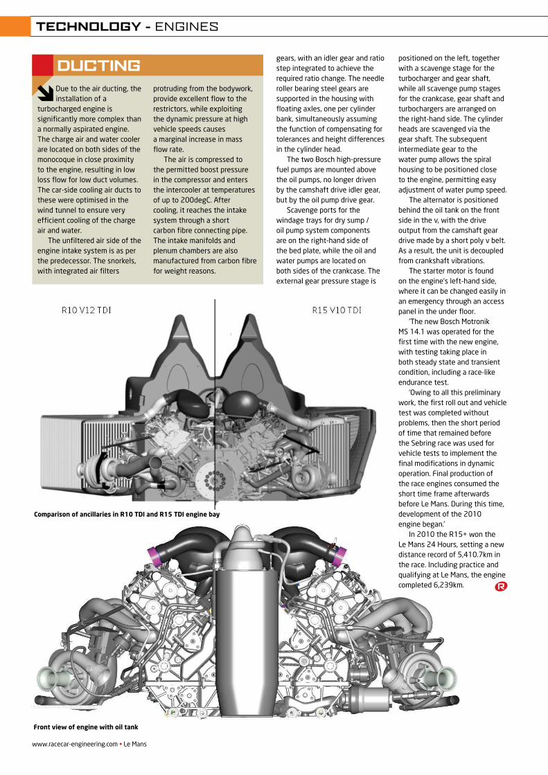
www.racecar-engineering.com • Le Mans
- 17 -
5. The engine in the car
The development of a diesel engine as thoroughbred race engine makes high demands. The task is further complicated by the necessity to integrate the engine perfectly in the very small overall package of a sports prototype. As with the R10, engine and car were designed as harmonic unit without weak points.
Picture 17: Comparison of R10 TDI and R15 TDI engine bay
Picture 18: R15 installed in the car
- 20 -
Picture 20: Front view of engine with oil tank 6. Engine development The decision, within the scope of the overall R15 concept to field a V10TDI at Le Mans, led to new constraints for engine mechanics and thermodynamics. The ideal displacement of 5.5 litres remained unchanged, the stroke-bore ratio, however, had to be changed. As a result the production based combustion process, many details of which had been so successfully developed with the future in mind over the years, could no longer be used. However, there was already an enormous amount of experience available owing to the intensive and comprehensive tests made on the R10 V12TDI. As had been the case with the V12TDI it was also advantageous that all the results from the single-cylinder dynamometer could be transferred entirely to the full engine. Because of this it was possible to develop faster and more cost effectively, and for the now new geometrical constraints to define a very broad matrix of components and component versions optimised thermodynamically. Below a list of the most important components and targets optimised within the constraints of the thermodynamic development: Air flow and charge exchange development
- Intake manifolds and air plenum - Valve timing - Inlet and exhaust channels (swirl and flow) - Gas exhaust
gears, with an idler gear and ratio step integrated to achieve the required ratio change. The needle roller bearing steel gears are supported in the housing with floating axles, one per cylinder bank, simultaneously assuming the function of compensating for tolerances and height differences in the cylinder head.
The two Bosch high-pressure fuel pumps are mounted above the oil pumps, no longer driven by the camshaft drive idler gear, but by the oil pump drive gear.
Scavenge ports for the windage trays for dry sump / oil pump system components are on the right-hand side of the bed plate, while the oil and water pumps are located on both sides of the crankcase. The external gear pressure stage is
positioned on the left, together with a scavenge stage for the turbocharger and gear shaft, while all scavenge pump stages for the crankcase, gear shaft and turbochargers are arranged on the right-hand side. The cylinder heads are scavenged via the gear shaft. The subsequent intermediate gear to the water pump allows the spiral housing to be positioned close to the engine, permitting easy adjustment of water pump speed.
The alternator is positioned behind the oil tank on the front side in the v, with the drive output from the camshaft gear drive made by a short poly v belt. As a result, the unit is decoupled from crankshaft vibrations.
The starter motor is found on the engine’s left-hand side, where it can be changed easily in an emergency through an access panel in the under floor.
‘The new Bosch Motronik MS 14.1 was operated for the first time with the new engine, with testing taking place in both steady state and transient condition, including a race-like endurance test.
‘Owing to all this preliminary work, the first roll out and vehicle test was completed without problems, then the short period of time that remained before the Sebring race was used for vehicle tests to implement the final modifications in dynamic operation. Final production of the race engines consumed the short time frame afterwards before Le Mans. During this time, development of the 2010 engine began.’
In 2010 the R15+ won the Le Mans 24 Hours, setting a new distance record of 5,410.7km in the race. Including practice and qualifying at Le Mans, the engine completed 6,239km.
Comparison of ancillaries in R10 TDI and R15 TDI engine bay
Front view of engine with oil tank
DuctingDue to the air ducting, the installation of a
turbocharged engine is significantly more complex than a normally aspirated engine. The charge air and water cooler are located on both sides of the monocoque in close proximity to the engine, resulting in low loss flow for low duct volumes. The car-side cooling air ducts to these were optimised in the wind tunnel to ensure very efficient cooling of the charge air and water.
The unfiltered air side of the engine intake system is as per the predecessor. The snorkels, with integrated air filters
protruding from the bodywork, provide excellent flow to the restrictors, while exploiting the dynamic pressure at high vehicle speeds causes a marginal increase in mass flow rate.
The air is compressed to the permitted boost pressure in the compressor and enters the intercooler at temperatures of up to 200degC. After cooling, it reaches the intake system through a short carbon fibre connecting pipe. The intake manifolds and plenum chambers are also manufactured from carbon fibre for weight reasons.
tEcHnOLOgY - ENGINES
REV21N7_Diesel-MPAC.indd 46 21/05/2012 10:02
Brake control from green light to chequered fl ag.
Pagid RS had a strong start to the 2012 racing season at the two classic US endurance races:24 h Daytona – All of the top 6 fi nishers overall and 60% of the entire fi eld used Pagid RS.12 h Sebring – 1st and 2nd in the World Endurance Championship with AF Corse Ferrari F458 Italia followed by Team Felbermayr Porsche 911 RSR, along with 55% of the GT fi eld used Pagid RS.
When it comes to brake modulation and control with ultimate reliance with a low wear rate, Pagid RS is your only choice. Race winners won’t settle for anything less.
www.pagidracing.com · [email protected]+49 6003 82 910Pagid is a registered trademark of TMD Friction
120403-anzeige-ferrari-e.indd 1 17.04.12 10:15

Untitled-83 1 10/27/11 10:10:00 AM