leakage inductance...
TRANSCRIPT

MeasuringLeakage
Inductance
VOLTECHNOTES
VPN 104-105/3
2
WHAT IS LEAKAGE INDUCTANCE?
VOLTECHNOTES
Main flux
No gap Windings Core
N1 N2
V1 V2
Leakage flux is a proportion of thetotal flux, stored in the primary windingMain fluxSmall
leakageinductance
Ideal transformer
© 2001 Voltech Instruments. All rights reserved.
Leakage inductance is an inductive component present in a transformer that results fromthe imperfect magnetic linking of one winding to another. Any magnetic flux that does notlink the primary winding to the secondary winding acts as inductive impedance in serieswith the primary, therefore this “leakage inductance” is shown on a schematic diagramas an additional inductance before the primary of an ideal transformer.
In certain applications, such as switched-mode power supplies and lighting ballasts,leakage inductance of the transformer may play a critical function in the product design.For this reason, accurate measurement of leakage inductance is often an important testfunction for transformer manufacturers. In order to avoid confusion with other transformercharacteristics, this technical note will not refer to other components of loss such aswinding resistance or inter-winding capacitance.
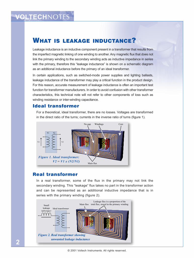
Ideal transformerFor a theoretical, ideal transformer, there are no losses. Voltages are transformedin the direct ratio of the turns; currents in the inverse ratio of turns (figure 1).
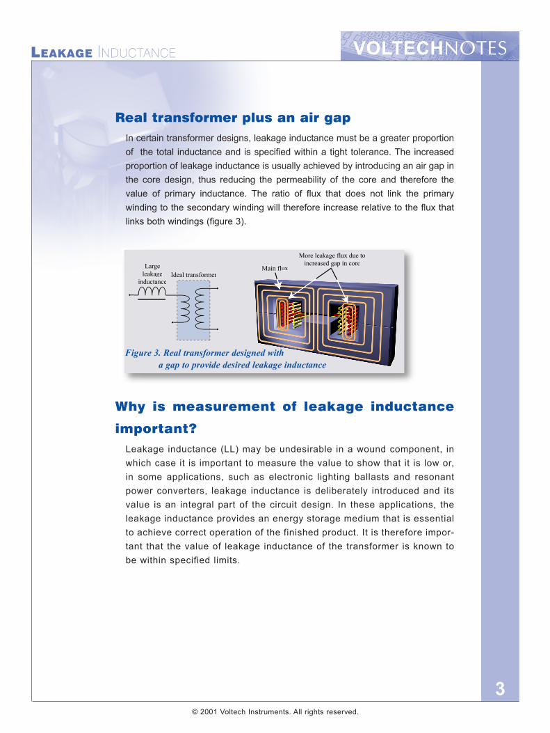
Real transformerIn a real transformer, some of the flux in the primary may not link thesecondary winding. This “leakage” flux takes no part in the transformer actionand can be represented as an additional inductive impedance that is inseries with the primary winding (figure 2).
Figure 1. Ideal transformer:V2 = V1 x (N2/N1)
Figure 2. Real transformer showing unwanted leakage inductance
VOLTECHNOTESLEAKAGE INDUCTANCE
3
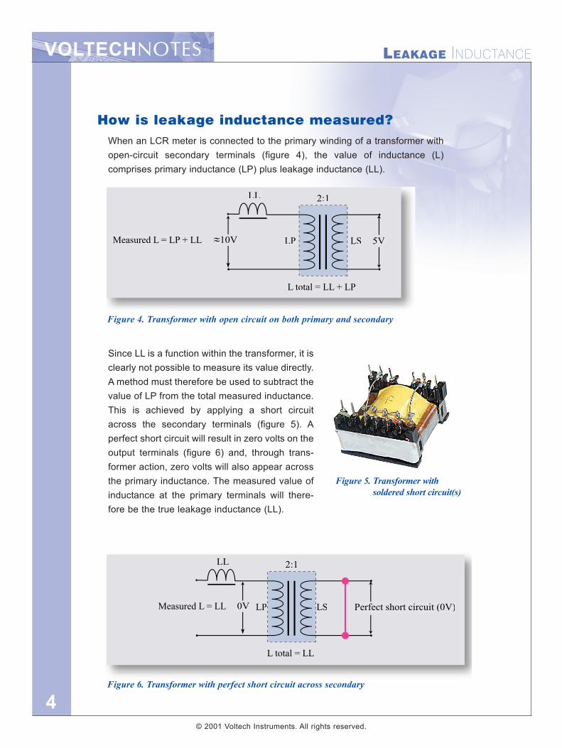
Real transformer plus an air gapIn certain transformer designs, leakage inductance must be a greater proportionof the total inductance and is specified within a tight tolerance. The increasedproportion of leakage inductance is usually achieved by introducing an air gap inthe core design, thus reducing the permeability of the core and therefore thevalue of primary inductance. The ratio of flux that does not link the primarywinding to the secondary winding will therefore increase relative to the flux thatlinks both windings (figure 3).
Why is measurement of leakage inductance
important?Leakage inductance (LL) may be undesirable in a wound component, inwhich case it is important to measure the value to show that it is low or,in some applications, such as electronic lighting ballasts and resonantpower converters, leakage inductance is deliberately introduced and itsvalue is an integral part of the circuit design. In these applications, theleakage inductance provides an energy storage medium that is essentialto achieve correct operation of the finished product. It is therefore impor-tant that the value of leakage inductance of the transformer is known tobe within specified limits.
More leakage flux due toincreased gap in core
Main fluxLargeleakage
inductanceIdeal transformer
Figure 3. Real transformer designed with a gap to provide desired leakage inductance
© 2001 Voltech Instruments. All rights reserved.
VOLTECHNOTES LEAKAGE INDUCTANCE
4
How is leakage inductance measured?When an LCR meter is connected to the primary winding of a transformer withopen-circuit secondary terminals (figure 4), the value of inductance (L)comprises primary inductance (LP) plus leakage inductance (LL).
Since LL is a function within the transformer, it isclearly not possible to measure its value directly.A method must therefore be used to subtract thevalue of LP from the total measured inductance.This is achieved by applying a short circuitacross the secondary terminals (figure 5). Aperfect short circuit will result in zero volts on theoutput terminals (figure 6) and, through trans-former action, zero volts will also appear acrossthe primary inductance. The measured value ofinductance at the primary terminals will there-fore be the true leakage inductance (LL).
L total = LL + LP
LP LS
2:1
5V
LL
10VMeasured L = LP + LL
Figure 4. Transformer with open circuit on both primary and secondary
L total = LL
Measured L = LL LP LS
2:1
Perfect short circuit (0V)
LL
0V
Figure 6. Transformer with perfect short circuit across secondary
Figure 5. Transformer withsoldered short circuit(s)
© 2001 Voltech Instruments. All rights reserved.
VOLTECHNOTESLEAKAGE INDUCTANCE
5
Voltage attributable toreflected short-circuit
impedance
Measured voltage onprimary attributable
to leakage impedanceand reflected s/c
impedance
Voltage attributable totrue leakage impedance
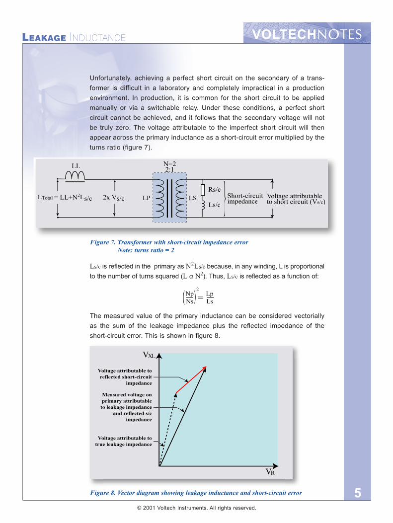
Unfortunately, achieving a perfect short circuit on the secondary of a trans-former is difficult in a laboratory and completely impractical in a productionenvironment. In production, it is common for the short circuit to be appliedmanually or via a switchable relay. Under these conditions, a perfect shortcircuit cannot be achieved, and it follows that the secondary voltage will notbe truly zero. The voltage attributable to the imperfect short circuit will thenappear across the primary inductance as a short-circuit error multiplied by theturns ratio (figure 7).
Ls/c is reflected in the primary as N2Ls/c because, in any winding, L is proportionalto the number of turns squared (L α N2). Thus, Ls/c is reflected as a function of:
The measured value of the primary inductance can be considered vectoriallyas the sum of the leakage impedance plus the reflected impedance of theshort-circuit error. This is shown in figure 8.
LSLP
N=22:1LL
2x Vs/cLTotal = LL+N2Ls/c Short-circuit impedance
Voltage attributableto short circuit (V
gh i i (Vs/c)
Rs/c
Ls/c
Figure 7. Transformer with short-circuit impedance errorNote: turns ratio = 2
Figure 8. Vector diagram showing leakage inductance and short-circuit error
NpNs
LpLs=
2
( (
© 2001 Voltech Instruments. All rights reserved.
VOLTECHNOTES LEAKAGE INDUCTANCE
6
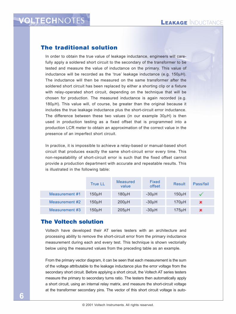
The traditional solutionIn order to obtain the true value of leakage inductance, engineers will care-fully apply a soldered short circuit to the secondary of the transformer to betested and measure the value of inductance on the primary. This value ofinductance will be recorded as the ‘true’ leakage inductance (e.g. 150µH).The inductance will then be measured on the same transformer after thesoldered short circuit has been replaced by either a shorting clip or a fixturewith relay-operated short circuit, depending on the technique that will bechosen for production. The measured inductance is again recorded (e.g.180µH). This value will, of course, be greater than the original because itincludes the true leakage inductance plus the short-circuit error inductance.The difference between these two values (in our example 30µH) is thenused in production testing as a fixed offset that is programmed into aproduction LCR meter to obtain an approximation of the correct value in thepresence of an imperfect short circuit.
In practice, it is impossible to achieve a relay-based or manual-based shortcircuit that produces exactly the same short-circuit error every time. Thisnon-repeatability of short-circuit error is such that the fixed offset cannotprovide a production department with accurate and repeatable results. Thisis illustrated in the following table:
The Voltech solutionVoltech have developed their AT series testers with an architecture andprocessing ability to remove the short-circuit error from the primary inductancemeasurement during each and every test. This technique is shown vectoriallybelow using the measured values from the preceding table as an example.
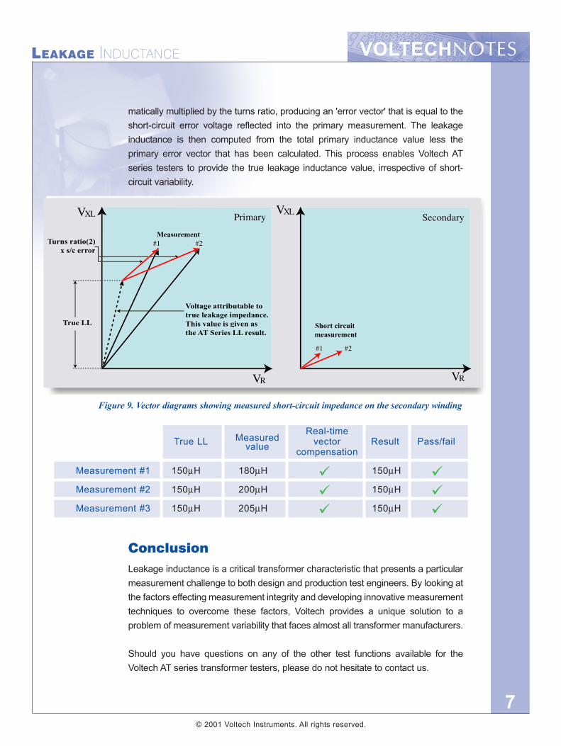
From the primary vector diagram, it can be seen that each measurement is the sumof the voltage attributable to the leakage inductance plus the error voltage from thesecondary short circuit. Before applying a short circuit, the Voltech AT series testersmeasure the primary to secondary turns ratio. The testers then automatically applya short circuit, using an internal relay matrix, and measure the short-circuit voltageat the transformer secondary pins. The vector of this short circuit voltage is auto-
True LL Measured Fixed Result Pass/failvalue offset
Measurement #1 150µH 180µH -30µH 150µH
Measurement #2 150µH 200µH -30µH 170µH
Measurement #3 150µH 205µH -30µH 175µH
© 2001 Voltech Instruments. All rights reserved.
VOLTECHNOTESLEAKAGE INDUCTANCE
7
matically multiplied by the turns ratio, producing an 'error vector' that is equal to theshort-circuit error voltage reflected into the primary measurement. The leakageinductance is then computed from the total primary inductance value less theprimary error vector that has been calculated. This process enables Voltech ATseries testers to provide the true leakage inductance value, irrespective of short-circuit variability.
ConclusionLeakage inductance is a critical transformer characteristic that presents a particularmeasurement challenge to both design and production test engineers. By looking atthe factors effecting measurement integrity and developing innovative measurementtechniques to overcome these factors, Voltech provides a unique solution to aproblem of measurement variability that faces almost all transformer manufacturers.
Should you have questions on any of the other test functions available for theVoltech AT series transformer testers, please do not hesitate to contact us.
Voltage attributable totrue leakage impedance.This value is given asthe AT Series LL result.
True LL Short circuitmeasurement
MeasurementTurns ratio(2)
x s/c error
MeasuredReal-time
True LL value vector Result Pass/failcompensation
Measurement #1 150µH 180µH 150µH
Measurement #2 150µH 200µH 150µH
Measurement #3 150µH 205µH 150µH
Figure 9. Vector diagrams showing measured short-circuit impedance on the secondary winding
© 2001 Voltech Instruments. All rights reserved.

VPN 104-105/3
VOLTECHNOTES
Voltech Instruments Ltd.148 Sixth Street
Harwell International Business Centre
Harwell, Didcot, Oxon OX11 0RA
United Kingdom
Telephone: +44 (0)1235 834555Facsimile: +44 (0)1235 835016E-mail: [email protected]
Voltech Instruments Inc.11637 Kelly Road, Suite 306
Fort Myers, FL 33908
U.S.A.
Telephone: +1 239 437 0494Facsimile: +1 239 437 3841
E-mail: [email protected]
www.voltech.com
Note: While every care has been taken in compiling the information for this publication, Voltech Instruments cannot accept legal liabil-ity for any inaccuracies. Voltech Instruments reserves the right to alter product specifications without notice and whenever necessaryto ensure optimum performance from its product range.