learning guide 1 - ndl.ethernet.edu.et
TRANSCRIPT

Ethiopian TVET
Program STEP-GIZ
CT program for Remote Teaching Title: Machining L-3
Perform Advanced Engineering Detail
Drafting
July 2020 Page 1 of 57
MACHINING
Level - III
Learning Guide 1 Unit of Competence: Perform Advanced Engineering Detail Drafting
Module Title: Performing Advanced Engineering Detail Drafting LG Code: IND MAC3 01 0217

Ethiopian TVET
Program STEP-GIZ
CT program for Remote Teaching Title: Machining L-3
Perform Advanced Engineering Detail
Drafting
July 2020 Page 2 of 57
Instruction Sheet Learning Guide #1
This learning guide is developed to provide you the necessary information regarding the following content
coverage and topics:
• Determine drawing requirements
• Prepare assembly, lay- out and detail drawing
• Quality assure drawing
This guide will also assist you to attain the learning outcome stated in the cover page. Specifically, upon
completion of this Learning Guide, you will be able to:
❖ drawing are checked and interpreted from work order Drawing, including auxiliary views,
sections and assemblies in ISO first and third angle projection are produced by using
manual instruments and CAD geometric tolerances and specifications.
❖ limits and fits assembly/fabrication is made possible based on applied standards
Learning Instructions:
1. Read the specific objectives of this Learning Guide.
2. Follow the instructions described below page 3 to 57.
3. Read the information written in the information sheet.
4. Accomplish the Self-check.
5. If you earned a satisfactory evaluation from the “Self-check”.
6. Do the “LAP test”.

Ethiopian TVET
Program STEP-GIZ
CT program for Remote Teaching Title: Machining L-3
Perform Advanced Engineering Detail
Drafting
July 2020 Page 3 of 57
Information Sheet-1 LO1: Determine drawing requirements
1. Determine drawing requirements
1.1. Check requirements and purpose of drawing from work order or similar
❖ Checking drawing requirements and purpose of drawing from work (customer) order is very essential
for any person who read drawing.
❖ Among the drawing requirement
➢ Necessary drawing equipment to prepare the drawing
➢ Necessary dimensions, symbols, and all information that complete the drawing.
➢ Any information which used for production of the given project including working (detail)
drawing.
Document Control Functions
The typical document control function does the following:
➢ Assign all part numbers, change numbers, and document revision levels.
➢ Control master design document after the appropriate point of initial release (master file, either
hard copy or electronic).
➢ Change request monitoring.
It is important, however, to assure that certain elements are present on drawing formats. It is also very
important to emphasize that certain data elements should not be on those formats.
Document Formats and Standards
Keep as few formats active as possible. A well thought out drafting standard will help in this area. Use
the commercially available Drawing Requirements Manual (DRM) as a guideline for your own
standard, taking care to assure that all the following rules and guidelines have been taken into account
as well. In other words, don’t just invoke one of these standards, read and modify it according to the
parts of this text that you wish to adopt, deleting those parts that are not applicable to your business.

Ethiopian TVET
Program STEP-GIZ
CT program for Remote Teaching Title: Machining L-3
Perform Advanced Engineering Detail
Drafting
July 2020 Page 4 of 57
Some general definition of the parts of design documents, regardless of size; drawings, specs, lists,
and other documents, should have a common format. They should all have a Body, Title Block, and
Revision Block, as seen in Fig. 1.1.
Fig. 1.1.
Drawing Requirements
When used in the field of the drawing, item numbers shall be enclosed in circular-shaped 1/2-inch-
diameter balloons.
The same find or item number shall be used for any group of reference designations assigned to
items of identical characteristics.
The item or find numbers on any drawing shall be assigned independently of those on any other
drawing. Find numbers assigned to subassemblies shown on an assembly drawing shall be
distinguished from those assigned to parts by adding a letter suffix to the subassembly find
number.
Purpose and Scope
Purpose
• Purpose is to describe the specification process, which defines the desired project result and
enumerates the project requirements.
Ethiopian TVET
Program STEP-GIZ
CT program for Remote Teaching Title: Machining L-3
Perform Advanced Engineering Detail
Drafting
July 2020 Page 5 of 57
Engineering departments document their agreements with other organizations in the form of
engineering specifications detailing the technical and project requirements of the system to be
provided.
It is important to note that managers and project leaders may introduce additional requirements,
such as further reviews or documentation, outside the technical specifications described in manual.
The design engineer must fulfill these requirements during the implementation of the engineering
project.
1.2. Source required information from workshop manuals, customer
specifications, product suppliers, and designers or similar.
Item Specifications
Specifications are words that describe an item. They are generally in a text format, but may have
text, charts, graphs, envelope drawings, or combinations of these and other techniques. They are
generally prepared to describe the end product, but may be defining a sublevel of the product.
The definition, therefore, becomes fairly general.
Definition: Specifications define the critical characteristics of an items form (appearance), physical, or
functional nature.
Specification Control Drawings are item specifications. Certain assemblies may be described by a
specification, whether made or purchased.
An assembly that is tested is usually defined by a test specification. There is one level of the
product that must have at least one specification that is the end product itself. These take various
forms and names. They will be called product specifications in this text.
Whatever they are called, they are so important that they need to be a released document and
under change control. When several products are combined into a system, the product
specification may be referred to as a System Integration Specification.
Product specifications requirements vary depending upon whether you are in a make to stock
make to order, or make to print environment.
Make-to-Stock Product Specifications

Ethiopian TVET
Program STEP-GIZ
CT program for Remote Teaching Title: Machining L-3
Perform Advanced Engineering Detail
Drafting
July 2020 Page 6 of 57
The single most important of all Design Documents is the Product Specification. This document must be
agreed upon by key company management. This agreement must occur very early in the product
definition phase.
❖ All Sources required information should be obtained from workshop manuals, customer
specifications, product suppliers, and designers or similar sources.
1.3. Plan Scope of drawing including layout, additional required information
and resources
➢ Scope; is limit or span or range of the project to be to be produced.
➢ Project Standards and Specification which should be regarded as a Recommended Practice,
specifies the minimum requirements for handling of a project in the detail design and procurement
stages.
❖ However, depending on the nature and extent of the contract between the Company and
Contractor, some parts/sections may be added, modified or deleted as required.
❖ The main activities for implementation of the detailed engineering, procurement services and
supply of equipment and materials are covered in this Standard Specification.
❖ The Project Standards and Specification does not deal with the construction/production activities
and/or efforts which normally should be made after or in parallel with the engineering phase for
completion of the project in the site.

Ethiopian TVET
Program STEP-GIZ
CT program for Remote Teaching Title: Machining L-3
Perform Advanced Engineering Detail
Drafting
July 2020 Page 7 of 57
Self-Check -1 Written Test
Self check questions
Choose the best answer from the best answer
1. ____________are words that describe an item.
A. Specifications
B. Symbols
C. Scope
D. All of the above
2. __________is limit or span or range of the project to be to be produced.
A. Scope
B. Symbols
C. Specifications
D. All of the above
3. Drawing Requirements
A. When used in the field of the drawing, item numbers shall be enclosed in circular-shaped 1/2-
inch-diameter balloons.
B. The same find or item number shall be used for any group of reference designations assigned
to items of identical characteristics.
C. The item or find numbers on any drawing shall be assigned independently of those on any
other drawing.
D. All of the above
4. One of the following is not true about Specifications
A. define the critical characteristics of an items form (appearance), physical, or functional nature
B. define the critical prices of an items form (appearance), physical, or functional nature
C. define the critical quantities of an items form (appearance), physical, or functional nature
D. All of the above

Ethiopian TVET
Program STEP-GIZ
CT program for Remote Teaching Title: Machining L-3
Perform Advanced Engineering Detail
Drafting
July 2020 Page 8 of 57
Answer for Self check questions
1. A
2. A
3. D
4. A
Ethiopian TVET
Program STEP-GIZ
CT program for Remote Teaching Title: Machining L-3
Perform Advanced Engineering Detail
Drafting
July 2020 Page 9 of 57
Information Sheet-2 LO2: Prepare assembly, lay-out and detail drawing
2.1. Determine drawing details, specifications
❖ Drawing detail and specification should be determined before start to design any project.
Working drawing is a set of drawing used during the work of making a product.
Working drawing
➢ Detail drawing
➢ Assembly drawing
Detail drawing is a multiview representation of a single part with dimensions and notes.
Assembly drawing is a drawing of various parts of a machine or structure assembled in their
relative working positions.
Purpose
Detail drawing conveys the information and instructions for manufacturing the part.
Assembly drawing conveys
1. Completed shape of the product.
2. Overall dimensions
3. Relative position of each part
4. Functional relationship among various components.
INFORMATION INDETAIL DRAWING
1. General information Title block
2. Part’s information
2.1. Shape description Object’s views
2.2. Size description
Ethiopian TVET
Program STEP-GIZ
CT program for Remote Teaching Title: Machining L-3
Perform Advanced Engineering Detail
Drafting
July 2020 Page 10 of 57
2.3 Specifications Notes
GENERAL INFORMATION
➢ Name of company
➢ Title of drawing (usually part’s name)
➢ Drawing sheet number
➢ Name of drafter, checker
➢ Relevant dates of action (drawn, checked, approved etc.)
➢ Revision table
➢ Unit
➢ Scale
➢ Method of projection
PART’ S INFORMATION
Shape
❖ Orthographic drawing
❖ Pictorial drawing
Size
❖ Dimensions and Tolerances
Specifications
❖ Part number, name, number required
❖ Type of material used
❖ General notes
❖ Heat treatment
❖ Surface finish
❖ General tolerances
RECOMMENDED PRACTICE
Draw one part to one sheet of paper.

Ethiopian TVET
Program STEP-GIZ
CT program for Remote Teaching Title: Machining L-3
Perform Advanced Engineering Detail
Drafting
July 2020 Page 11 of 57
If not the case,
- apply enough spacing between parts.
- draw all parts using the same scale.
Otherwise, the scale should be clearly note under each part’s drawing.
Standard parts such as bolt, nut, pin, and bearing do not require detail drawings.
Part No., Part name, material, Number required
Notes
Unit, fillets & rounds sizes etc.
Completed dimension
orthographic drawing
Title block
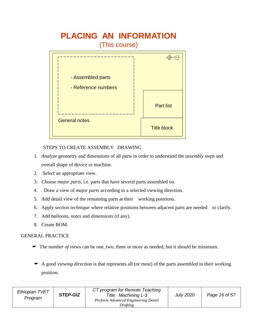
PLACING AN INFORMATION(This course)

Ethiopian TVET
Program STEP-GIZ
CT program for Remote Teaching Title: Machining L-3
Perform Advanced Engineering Detail
Drafting
July 2020 Page 12 of 57
EXAMPLE : Interpreting detail drawing
General note
Revision table
Title block
1. Orthographic
views
2. Dimensions
& Tolerances
3. Surface
finishing
ProjectionGen. tolerance
TYPES OF ASSEMBLY DRAWING
1. Exploded assembly drawings
The parts are separately display, but they are aligned according to their assembly positions and sequences.
2. General assembly drawings.
All parts are drawn in their working position.
3. Detail assembly drawings
All parts are drawn in their working position with a completed dimensions.

Ethiopian TVET
Program STEP-GIZ
CT program for Remote Teaching Title: Machining L-3
Perform Advanced Engineering Detail
Drafting
July 2020 Page 13 of 57
1. EXPLODED ASSEMBLY
Pictorial representation
Finished product
2. GENERAL ASSEMBLY
Pictorial Orthographic

Ethiopian TVET
Program STEP-GIZ
CT program for Remote Teaching Title: Machining L-3
Perform Advanced Engineering Detail
Drafting
July 2020 Page 14 of 57
3. DETAILED ASSEMBLY(working-drawing assembly)

Ethiopian TVET
Program STEP-GIZ
CT program for Remote Teaching Title: Machining L-3
Perform Advanced Engineering Detail
Drafting
July 2020 Page 15 of 57
DETAIL AND ASSEMBLY DRAWINGS
DETAIL ASSEMBLY DRAWING OF A SAWHORSE
REQUIRED INFORMATION IN GENERAL ASSEMBLY DRAWING
1. Part list (or bill of materials, BOM)
2. Part list (or bill of materials, BOM)
1. Item number
2. Descriptive name
3. Material, MATL.
4. Quantity required (per a unit of machine), QTY.
3. Leader lines with balloons around part numbers.
4. Machining and assembly operations and critical dimensions related to operation of the
machine.
Ethiopian TVET
Program STEP-GIZ
CT program for Remote Teaching Title: Machining L-3
Perform Advanced Engineering Detail
Drafting
July 2020 Page 16 of 57
- Assembled parts
- Reference numbers
General notes
Title block
Part list
PLACING AN INFORMATION(This course)
STEPS TO CREATE ASSEMBLY DRAWING
1. Analyze geometry and dimensions of all parts in order to understand the assembly steps and
overall shape of device or machine.
2. Select an appropriate view.
3. Choose major parts, i.e. parts that have several parts assembled on.
4. . Draw a view of major parts according to a selected viewing direction.
5. Add detail view of the remaining parts at their working positions.
6. Apply section technique where relative positions between adjacent parts are needed to clarify.
7. Add balloons, notes and dimensions (if any).
8. Create BOM.
GENERAL PRACTICE
The number of views can be one, two, three or more as needed, but it should be minimum.
A good viewing direction is that represents all (or most) of the parts assembled in their working
position.
Ethiopian TVET
Program STEP-GIZ
CT program for Remote Teaching Title: Machining L-3
Perform Advanced Engineering Detail
Drafting
July 2020 Page 17 of 57
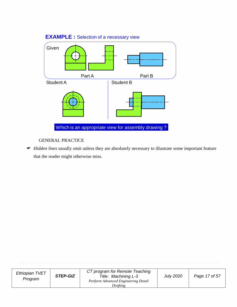
Part A Part B
EXAMPLE : Selection of a necessary view
Given
Student A Student B
Which is an appropriate view for assembly drawing ?
GENERAL PRACTICE
Hidden lines usually omit unless they are absolutely necessary to illustrate some important feature
that the reader might otherwise miss.

Ethiopian TVET
Program STEP-GIZ
CT program for Remote Teaching Title: Machining L-3
Perform Advanced Engineering Detail
Drafting
July 2020 Page 18 of 57
GENERAL PRACTICESection technique is usually need to clarify
mating of the parts.
Correct
Better
Part A
Part B
OFF
Use different section line styles for adjacent parts.
ONColor
Ethiopian TVET
Program STEP-GIZ
CT program for Remote Teaching Title: Machining L-3
Perform Advanced Engineering Detail
Drafting
July 2020 Page 19 of 57
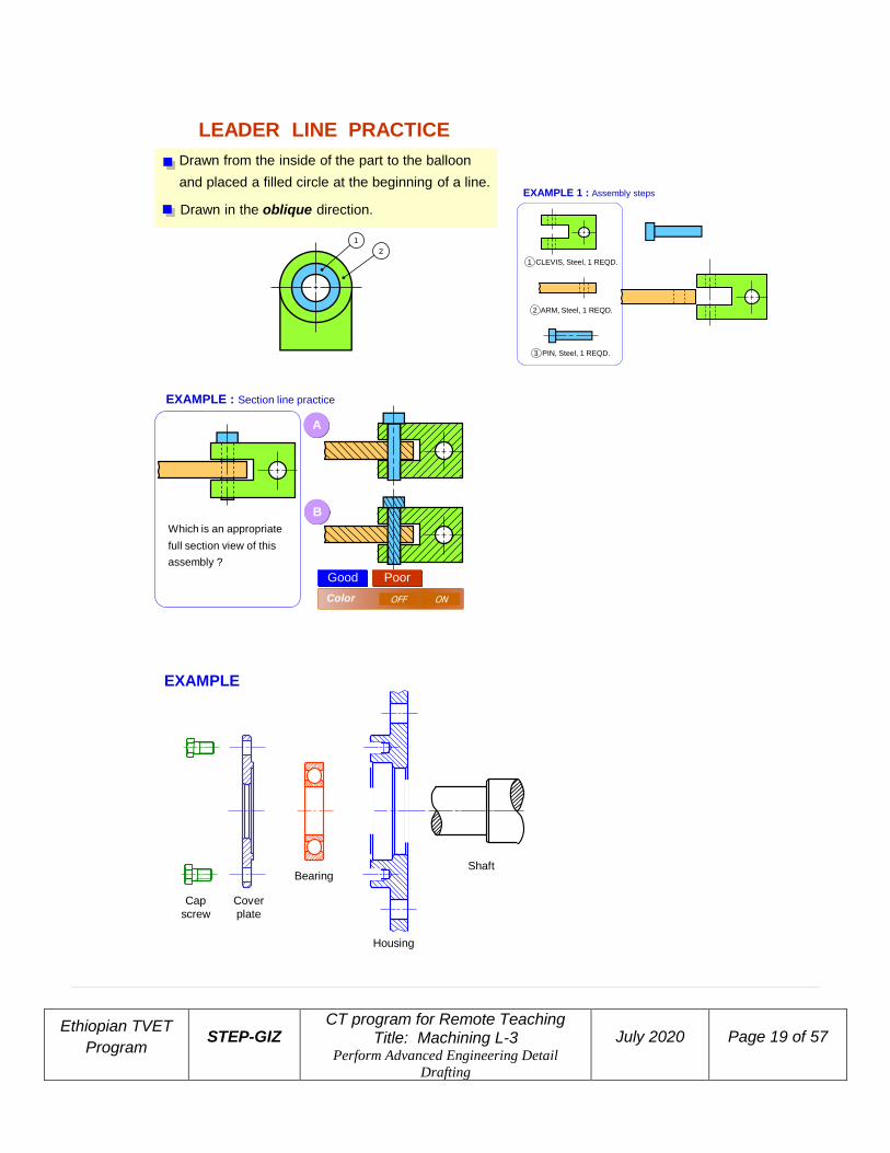
LEADER LINE PRACTICE
Drawn in the oblique direction.
Drawn from the inside of the part to the balloon
and placed a filled circle at the beginning of a line.
1
2
EXAMPLE 1 : Assembly steps
3 PIN, Steel, 1 REQD.
2 ARM, Steel, 1 REQD.
1 CLEVIS, Steel, 1 REQD.
EXAMPLE : Section line practice
A
B
Which is an appropriate
full section view of this
assembly ?
Good Poor
OFF ONColor
Shaft
Housing
Bearing
Cover
plate
Cap
screw
EXAMPLE
Ethiopian TVET
Program STEP-GIZ
CT program for Remote Teaching Title: Machining L-3
Perform Advanced Engineering Detail
Drafting
July 2020 Page 20 of 57
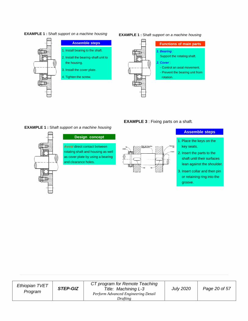
EXAMPLE 1 : Shaft support on a machine housing
Assemble steps
1. Install bearing to the shaft.
2. Install the bearing-shaft unit to
the housing.
3. Install the cover plate.
4. Tighten the screw.
1. Bearing :
Support the rotating shaft.
2. Cover :
- Control an axial movement.
- Prevent the bearing unit from
rotation.
Functions of main parts
EXAMPLE 1 : Shaft support on a machine housing
Avoid direct contact between
rotating shaft and housing as well
as cover plate by using a bearing
and clearance holes.
EXAMPLE 1 : Shaft support on a machine housing
Design concept
EXAMPLE 3 : Fixing parts on a shaft.
1. Place the keys on the
key seats.
2. Insert the parts to the
shaft until their surfaces
lean against the shoulder.
3. Insert collar and then pin
or retaining ring into the
groove.
Assemble steps

Ethiopian TVET
Program STEP-GIZ
CT program for Remote Teaching Title: Machining L-3
Perform Advanced Engineering Detail
Drafting
July 2020 Page 21 of 57
EXAMPLE : Fixing parts on a shaft.
Retaining ring can resist
lower axial force than collar
& pin unit.
Design concept
EXAMPLE : Parts with tapered holes on tapered shaft.
1. Insert the part on the
tapered end of the shaft.
2. Insert the washer
(non-standard).
3. Tightening the nut.
Assemble steps
EXAMPLE : Parts with tapered holes on tapered shaft.
1. Washer :
- Improve the distribution
the tightening force on
the part.
Function
EXAMPLE : Parts with tapered holes on tapered shaft.
Length of the tapered
portion and depth of the
tapered hole require a
calculation.
Design concept
EXAMPLE : Parts having preloaded spring
1. Insert the spring into the casing.
2. Tighten the rod to the spring
loader.
3. Close the cap and tighten.
Spring in
free length
Assemble steps

Ethiopian TVET
Program STEP-GIZ
CT program for Remote Teaching Title: Machining L-3
Perform Advanced Engineering Detail
Drafting
July 2020 Page 22 of 57
EXAMPLE : Parts having preloaded spring
1. Spring plunger :
- Transmit a force from rod to
spring.
- Keep the spring in a position.
Function
EXAMPLE : Parts having preloaded spring
Spring plunger has a spherical
surface contacts to the cap;
therefore, the rod can align itself
to original position.
Design concept
POINTS TO CONSIDER
1. Surface finishing
2. Tolerance
- Size
- Geometry
SURFACE FINISHING
Surface finishing means the quality of a surface. It relates to the level of roughness of a surface.
Purpose
1. To control the accuracy in positioning and tightness between mating parts.
2. To reduce the friction, especially for the part moves relative to other parts.
TOLERANCE
Tolerance is the total amount dimension may vary.
It is defined as the difference between the upper and lower limits.
Purpose
1. To control an interchangeability of parts.
2. To ensures the mating part will have a desired fit

Ethiopian TVET
Program STEP-GIZ
CT program for Remote Teaching Title: Machining L-3
Perform Advanced Engineering Detail
Drafting
July 2020 Page 23 of 57
2.2. Insert dimensions and geometric tolerances
Tolerances: Engineers realize that absolute accuracy is impossible, so they figure how much
variation is permissible. This allowance is known as tolerance.
Tolerances is stated on a drawing as (plus or minus) a certain amount, either by a
Fraction or
Decimal.
Limits are the maximum and/or minimum values prescribed for a specific dimension, while
tolerance represents the total amount by which a specific dimension may vary.
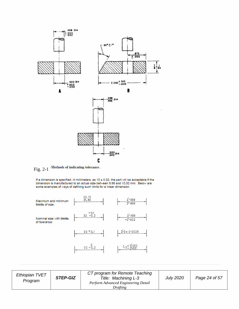
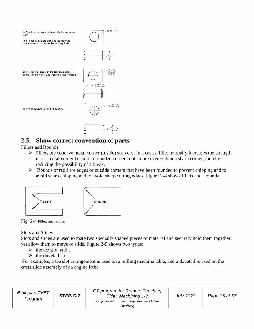
Tolerances may be shown on drawings by several different methods; figure 2-1 shows three
examples.
❖ The unilateral method (view A), is used when variation from the design size is permissible
in one direction only.
❖ In the bilateral method (view B), the dimension figure shows the plus or minus variation
that is acceptable. In the limit dimensioning method (view C), the maximum and minimum
measurements are both stated.
Ethiopian TVET
Program STEP-GIZ
CT program for Remote Teaching Title: Machining L-3
Perform Advanced Engineering Detail
Drafting
July 2020 Page 24 of 57
Fig. 2-1

Ethiopian TVET
Program STEP-GIZ
CT program for Remote Teaching Title: Machining L-3
Perform Advanced Engineering Detail
Drafting
July 2020 Page 25 of 57
The surfaces being tolerance have geometrical characteristics such as roundness, or perpendicularity to
another surface. Figure 2-2 shows typical geometrical characteristic symbols. A datum is a surface, line,
or point from which a geometric position is to be determined or from which a distance is to be measured.
Any letter of the alphabet except I, O, and Q may be used as a datum identifying symbol.
2.3. Include appropriate symbols for limits and fits, surface texture…

Ethiopian TVET
Program STEP-GIZ
CT program for Remote Teaching Title: Machining L-3
Perform Advanced Engineering Detail
Drafting
July 2020 Page 26 of 57
Fig. 2-2 Geometric characteristic symbols.
Datum • Datum surfaces and datum features are used as references to control other features on a part.
• Datum features can be actual features on the part, such as a point, line, plane, cylinder, or other
geometric form assumed to be exact.
A feature control symbol is made of geometric symbols and tolerances. Figure 2-3 shows how a
feature control symbol may include datum references.
Fig. 2-3 Feature control frame indicating a datum reference.
Flatness
Ethiopian TVET
Program STEP-GIZ
CT program for Remote Teaching Title: Machining L-3
Perform Advanced Engineering Detail
Drafting
July 2020 Page 27 of 57
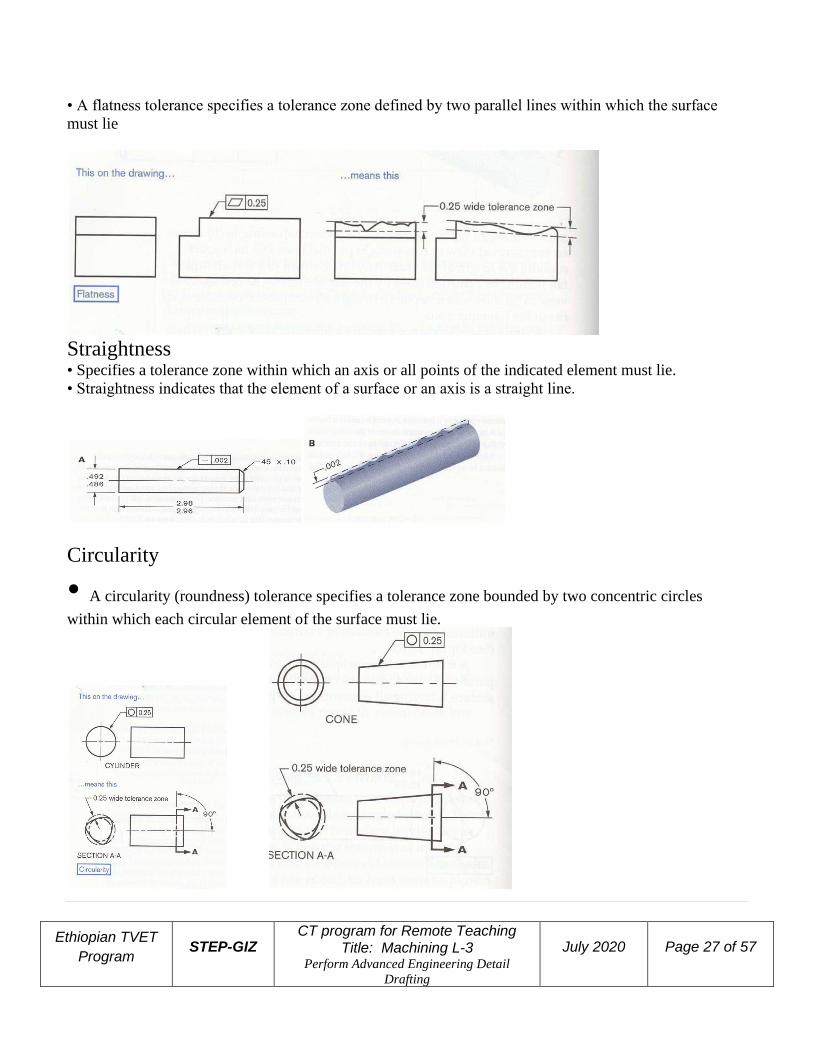
• A flatness tolerance specifies a tolerance zone defined by two parallel lines within which the surface
must lie
Straightness • Specifies a tolerance zone within which an axis or all points of the indicated element must lie.
• Straightness indicates that the element of a surface or an axis is a straight line.
Circularity
• A circularity (roundness) tolerance specifies a tolerance zone bounded by two concentric circles
within which each circular element of the surface must lie.

Ethiopian TVET
Program STEP-GIZ
CT program for Remote Teaching Title: Machining L-3
Perform Advanced Engineering Detail
Drafting
July 2020 Page 28 of 57
Cylindricity
• A cylindricity tolerance specifies a tolerance zone bounded by concentric cylinders within which the
surface must lie.
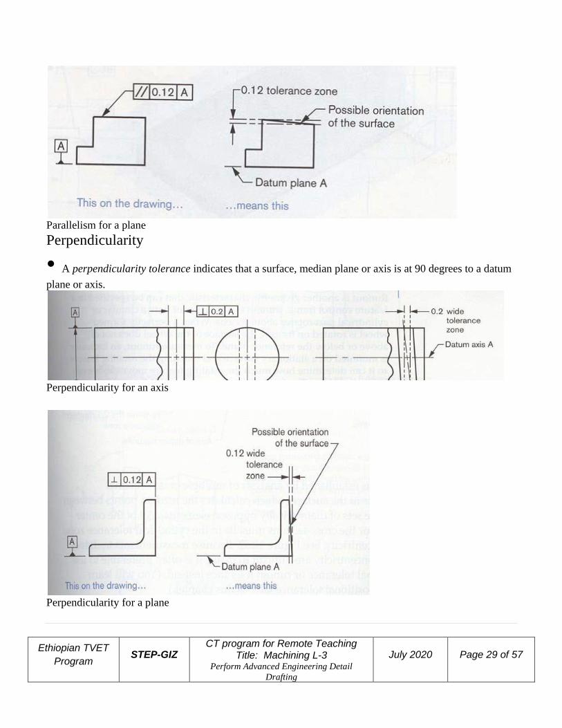
Parallelism
• A parallelism tolerance specifies a tolerance zone defined by two parallel planes or by two lines
parallel to a datum plane or axis within which the surface or axis of the feature must lie
Parallelism for an axis
Ethiopian TVET
Program STEP-GIZ
CT program for Remote Teaching Title: Machining L-3
Perform Advanced Engineering Detail
Drafting
July 2020 Page 29 of 57
Parallelism for a plane
Perpendicularity
• A perpendicularity tolerance indicates that a surface, median plane or axis is at 90 degrees to a datum
plane or axis.
Perpendicularity for an axis
Perpendicularity for a plane

Ethiopian TVET
Program STEP-GIZ
CT program for Remote Teaching Title: Machining L-3
Perform Advanced Engineering Detail
Drafting
July 2020 Page 30 of 57
Concentricity A concentricity tolerance indicates that a cylinder, cone, hex, square or surface of revolution
shares a common axis with a datum feature. It controls the location for the axis of the indicated
feature within a cylindrical tolerance zone whose axis coincides with the datum axis.
Other Form Tolerances are
➢ Profile tolerance
➢ Positional tolerance
➢ Angularity
2.3.1.Limits and fits for shafts and holes
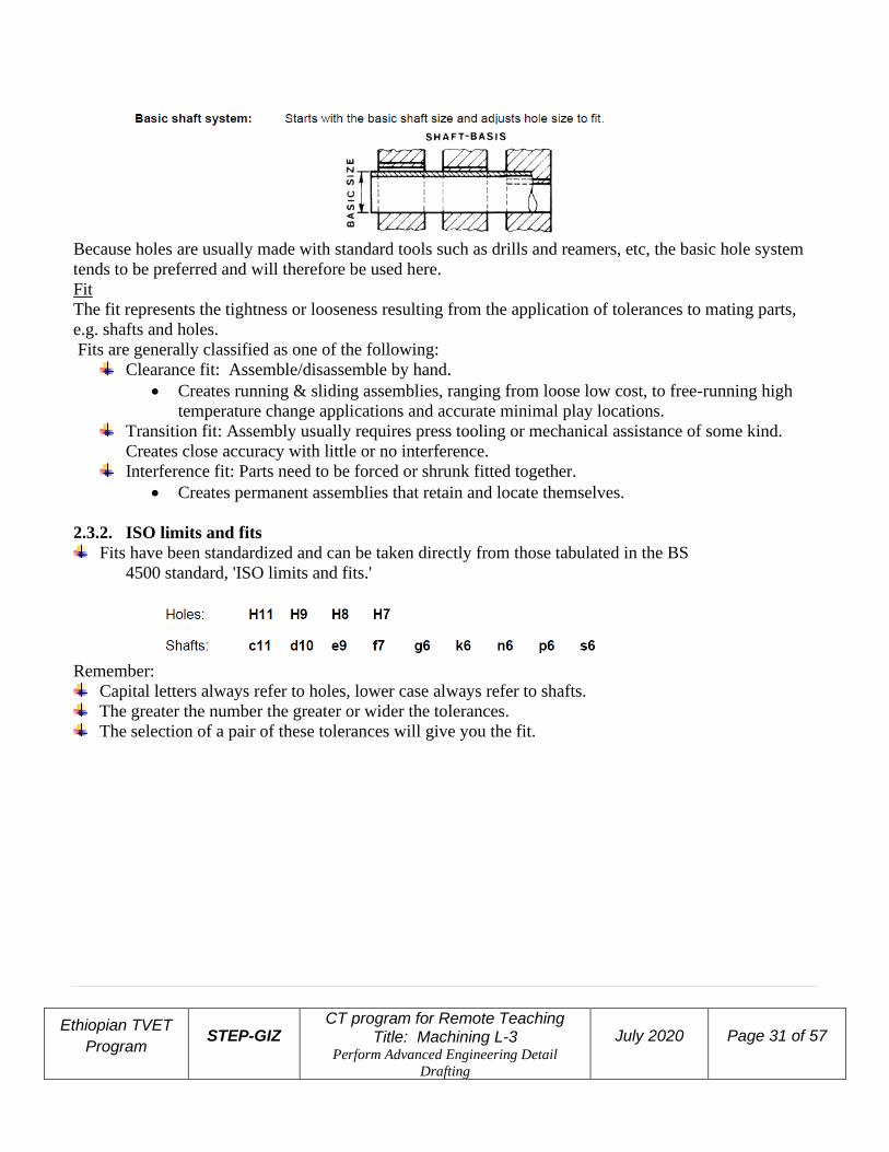
Basic size and shaft/hole tolerance systems
The basic size or nominal size is the size of shaft or hole that the designer specifies before applying the
limits to it. There are two systems used for specifying shaft/hole tolerances:
Ethiopian TVET
Program STEP-GIZ
CT program for Remote Teaching Title: Machining L-3
Perform Advanced Engineering Detail
Drafting
July 2020 Page 31 of 57
Because holes are usually made with standard tools such as drills and reamers, etc, the basic hole system
tends to be preferred and will therefore be used here.
Fit
The fit represents the tightness or looseness resulting from the application of tolerances to mating parts,
e.g. shafts and holes.
Fits are generally classified as one of the following:
Clearance fit: Assemble/disassemble by hand.
• Creates running & sliding assemblies, ranging from loose low cost, to free-running high
temperature change applications and accurate minimal play locations.
Transition fit: Assembly usually requires press tooling or mechanical assistance of some kind.
Creates close accuracy with little or no interference.
Interference fit: Parts need to be forced or shrunk fitted together.
• Creates permanent assemblies that retain and locate themselves.
2.3.2. ISO limits and fits
Fits have been standardized and can be taken directly from those tabulated in the BS
4500 standard, 'ISO limits and fits.'
Remember:
Capital letters always refer to holes, lower case always refer to shafts.
The greater the number the greater or wider the tolerances.
The selection of a pair of these tolerances will give you the fit.

Ethiopian TVET
Program STEP-GIZ
CT program for Remote Teaching Title: Machining L-3
Perform Advanced Engineering Detail
Drafting
July 2020 Page 32 of 57

Ethiopian TVET
Program STEP-GIZ
CT program for Remote Teaching Title: Machining L-3
Perform Advanced Engineering Detail
Drafting
July 2020 Page 33 of 57
Ethiopian TVET
Program STEP-GIZ
CT program for Remote Teaching Title: Machining L-3
Perform Advanced Engineering Detail
Drafting
July 2020 Page 34 of 57
2.4. Undertake Engineering calculations, dimensions limits and fits,
surface texture, datum references and geometric tolerances
ISO limits and fits, determining working limits.
Ethiopian TVET
Program STEP-GIZ
CT program for Remote Teaching Title: Machining L-3
Perform Advanced Engineering Detail
Drafting
July 2020 Page 35 of 57
2.5. Show correct convention of parts Fillets and Rounds
➢ Fillets are concave metal corner (inside) surfaces. In a cast, a fillet normally increases the strength
of a metal corner because a rounded corner cools more evenly than a sharp corner, thereby
reducing the possibility of a break.
➢ Rounds or radii are edges or outside corners that have been rounded to prevent chipping and to
avoid sharp chipping and to avoid sharp cutting edges. Figure 2-4 shows fillets and rounds.
Fig. 2-4 Fillets and rounds
Slots and Slides
Slots and slides are used to mate two specially shaped pieces of material and securely hold them together,
yet allow them to move or slide. Figure 2-5 shows two types:
➢ the tee slot, and t
➢ the dovetail slot.
For examples, a tee slot arrangement is used on a milling machine table, and a dovetail is used on the
cross slide assembly of an engine lathe.

Ethiopian TVET
Program STEP-GIZ
CT program for Remote Teaching Title: Machining L-3
Perform Advanced Engineering Detail
Drafting
July 2020 Page 36 of 57
Fig 2-5 Slots and slides.
Keys, Key seats, and Keyways
A key is a small wedge or rectangular piece of metal inserted in a slot or groove between a shaft and a hub
to prevent slippage. Figure 2-6 shows three types of keys.
Fig. 2-6 three types of keys
Figure 2-7 shows a key seat and keyway .View shows a key seat, which is a slot or groove on the outside
of a part into which the key fits. View B shows a keyway, which is a slot or groove within a cylinder,
tube, or pipe. A key fitted into a key seat will slide into the keyway and prevent movement of the parts.
Fig. 2-7 A key seat and keyway.

Ethiopian TVET
Program STEP-GIZ
CT program for Remote Teaching Title: Machining L-3
Perform Advanced Engineering Detail
Drafting
July 2020 Page 37 of 57
Fig. 2-12 Thread representations in drawing
2.6. Produce drawing in third angle projection
Preparing Engineering Drawings
Usually engineering drawings (of real life objects) are prepared in three stages;
➢ sketches,
➢ hand drafts and
➢ Detail drawings. This sequence is not very binding but most workers find it very useful to work in
that order.
Sketches
➢ Sketching is almost always the first step in the preparation of Engineering Drawings (ED). The
work piece (object) is carefully studied and all the necessary dimensions are measured. The views
that are necessary to completely describe the object are very roughly drawn (free hand). All
dimensions are indicated on the sketch as deemed necessary.
Ethiopian TVET
Program STEP-GIZ
CT program for Remote Teaching Title: Machining L-3
Perform Advanced Engineering Detail
Drafting
July 2020 Page 38 of 57
Working Drawings
working drawings are EDs presenting single items (object/machine component/work piece etc).
They are meant to enable the person in a workshop to produce (by
machining/casting/forging/fabricating etc) the desired item. Such details as dimensional
tolerances, surface finish, special treatments, material to be used for the component etc are
specified.
The number of views to be presented depends on the complexity of the item. In many situations,
sectional views are included to show hidden details that could not conveniently and explicitly
appear in any external view. The scale used for the detail drawing should allow a clear
understanding of the drawing (i.e. use enlargements and/or reductions as you find it appropriate).
Sometimes just a small portion of the drawing is enlarged to show all the details. Such partial
enlargements are normally included in the same drawing. When the item is drawn much enlarged,
it is recommended to add a picture (drawing) to true size for more information.
Some Basic Instruments and Equipment
Detail Drawings are prepared with the aid of special instruments and/or equipment. It would have been
extremely difficult for most people to prepare EDs according to the required standards/specifications
without the aid of such instruments. The following are the basic drafting tools worth understanding:
➢ T-Square
➢ Set Square
➢ Drafting Machine
➢ Rule Scale
➢ Wooden Pencil

Ethiopian TVET
Program STEP-GIZ
CT program for Remote Teaching Title: Machining L-3
Perform Advanced Engineering Detail
Drafting
July 2020 Page 39 of 57
➢ Mechanical Drawing Pencils
➢ Erasing Shield
➢ Auto CAD and Catia
➢ General Guidelines
➢ Spacing of Views
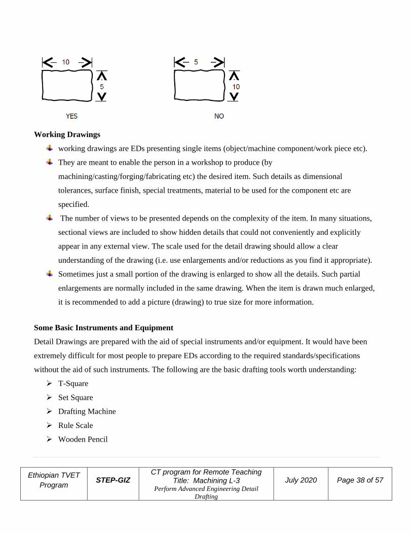
Spacing of views on the drawing paper is extremely important. The general appearance of the drawing
is significantly affected if the different views are poorly spaced. Spacing of views requires us to place the
views on the drawing paper such that the spaces between the views and between the views and the
limits of the drawing space are roughly equal (horizontally and vertically).
Steps
1. Decide on the views to be drawn (i.e. FV, LHSV and TV)
2. Determine the extreme dimensions of the different views to be drawn

Ethiopian TVET
Program STEP-GIZ
CT program for Remote Teaching Title: Machining L-3
Perform Advanced Engineering Detail
Drafting
July 2020 Page 40 of 57
3. Determine the required space, based on the scale to be used, both along the horizontal and vertical
directions
4. Divide the “free space” into three equal portions, both horizontally and vertically. This will give you X
and Y
It repeats until a satisfactory solution has evolved, as indicated in the flow diagram above.
The design model
❖ The concept of the designer working with a model of a design is fundamental to the design
process.

Ethiopian TVET
Program STEP-GIZ
CT program for Remote Teaching Title: Machining L-3
Perform Advanced Engineering Detail
Drafting
July 2020 Page 41 of 57
❖ The design model is a representation of the design. This model could be anything from a few ideas
in the designers head, through to rough sketches and notes, calculations, sets of detailed formal
engineering drawings; computer generated 3D representations, physical prototypes, etc.
❖ The design model would be used by the designer to record and develop ideas and to provide a
basis to evaluate the design.
❖ Larger design projects are undertaken by more than one engineer. Design models are used to
communicate and demonstrate ideas between all those concerned with the product design,
development, manufacture and use.
❖ A designer needs to have the skills to generate and work with this model in order to communicate
ideas and develop a design.
To determine any drawing details, specifications we have to prepare Orthographic
projection.
The word orthographic means to draw at right angles and is derived from the Greek words
Figure 2.1a, two right angle planes of projection.
ORTHOS - straight, rectangular, upright
GRAPHOS - written, drawn
➢ Orthographic projection is the graphical method used in modern engineering drawing.
➢ In order to interpret and communicate with engineering drawings a designer must have a
sound understanding of it's use and a clear vision of how the various projections are created.

Ethiopian TVET
Program STEP-GIZ
CT program for Remote Teaching Title: Machining L-3
Perform Advanced Engineering Detail
Drafting
July 2020 Page 42 of 57
There are two predominant orthographic projections used today.
➢ First angle projection
➢ Third angle projection
Figure 2.1b.Quadrant representation
Orthographic projection symbols

Ethiopian TVET
Program STEP-GIZ
CT program for Remote Teaching Title: Machining L-3
Perform Advanced Engineering Detail
Drafting
July 2020 Page 43 of 57
2.7. Produce all drawings in an acceptable standard/ISO
First angle projection

Ethiopian TVET
Program STEP-GIZ
CT program for Remote Teaching Title: Machining L-3
Perform Advanced Engineering Detail
Drafting
July 2020 Page 44 of 57
Figure 1.2d. A completed First angle projection drawing
Third angle projection
The construction method used is the same. The difference between first and third angle projection when
creating and reading really lies with the positions of the views. For the same component, an orthographic
projection drawing with the same front, side and plan views would look like Figure 2. below.
Ethiopian TVET
Program STEP-GIZ
CT program for Remote Teaching Title: Machining L-3
Perform Advanced Engineering Detail
Drafting
July 2020 Page 45 of 57
2.8. Select components, material and/or assemblies from data sheets
2.9. Insert dimensions and geometric tolerances of various components
Dimensioning
➢ To enable productions of machine parts/components, all the relevant dimensions have to appear on
the drawing. The practice is that any dimension is shown only once in that view in which it
appears more explicitly. For this reason, it is not surprising that most of the important dimensions
appear in the front view.
➢ Repetitions are discouraged unless clarity necessitates this. To keep the drawing clean, it is
advised to put all the dimensions outside the drawing, except where and when this is unavoidable.
➢ There are three types of dimensions;
Functional Dimensions (FD),
Non-Functional Dimensions (NFD) and
Auxiliary Dimensions (AD)
Functional Dimensions (FDs)
These are dimensions, which directly dictate the functioning of the component. That is a FD is a
dimension defined on the basis of the function of the product and the method of locating it in any
assembly of which it may form part of, e.g. the diameter of a shaft, the length of a bolt, etc.
Non-Functional Dimensions (NFDs)
These are dimensions, which do not directly affect the functioning of the component but have to
be specified to enable production of that component, e.g. the size of a bolt head.
Auxiliary Dimensions (ADs)
These are dimensions which should not necessarily appear on the drawing but are sometimes included to
avoid calculations or when they would provide additional/useful information. ADs are usually written in
brackets.

Ethiopian TVET
Program STEP-GIZ
CT program for Remote Teaching Title: Machining L-3
Perform Advanced Engineering Detail
Drafting
July 2020 Page 46 of 57
General Hints on Dimensioning
NOTE that all “rules” on dimensioning are just guidelines. Use common sense depending on
circumstances (i.e. there are no strict rules/regulations on dimensioning)
In metric system, all linear dimensions are considered to be in millimeters
Show full size dimensions regardless of the scale used in the drawing
Dimension in a manner that makes it unnecessary to calculate any required size information
For any feature, place the dimensions where the feature appears most explicitly
Dimension any feature only once (i.e. no repetitions are allowed)
Dimension obviously identical features only once

Ethiopian TVET
Program STEP-GIZ
CT program for Remote Teaching Title: Machining L-3
Perform Advanced Engineering Detail
Drafting
July 2020 Page 47 of 57

Ethiopian TVET
Program STEP-GIZ
CT program for Remote Teaching Title: Machining L-3
Perform Advanced Engineering Detail
Drafting
July 2020 Page 48 of 57
Self-check
Self-check questions
Choose the best answer from the best answer
1. One of the following is true about Functional Dimensions (FDs)
A. These are dimensions, which directly dictate the functioning of the component.
B. FD is a dimension defined on the basis of the function of the product
C. The method of locating it in any assembly of which it may form part of, e.g. the diameter of a
shaft, the length of a bolt, etc.
D. All of the above
2. Non-Functional Dimensions (NFDs)
A. These are dimensions, which do not directly affect the functioning of the component
B. The size of a bolt head is example of NFDs
C. It is very basic for the component
D. A & B E. All of the above
3. One of the following is true about Auxiliary Dimensions (ADs)
A. It is very basic for the component
B. These are dimensions which should not necessarily appear on the drawing but are sometimes
included to avoid calculations
C. They would provide additional/useful information and ADs are usually written in brackets.
D. A & B E. B & C
4. One of the following is not types of dimensions
A. Functional Dimensions (FD)
B. Non-Functional Dimensions (NFD)
C. Auxiliary Dimensions (AD)
D. None
5. First angle projection is more common in
A. America (USA)
B. Unit Kingdom

Ethiopian TVET
Program STEP-GIZ
CT program for Remote Teaching Title: Machining L-3
Perform Advanced Engineering Detail
Drafting
July 2020 Page 49 of 57
C. Europe
D. All of the above
6. ______________________is the graphical method used in modern engineering drawing.
A. Orthographic projection
B. Geometric development
C. Sketching
D. All of the above
7. A____________ is a small wedge or rectangular piece of metal inserted in a slot or groove between a
shaft and a hub to prevent slippage.
A. Key C. Rivet
B. Shaft D. None
8. For H8 and f7 or H11 and c11, H, f or c represents
A. Shaft and hole respectively
B. Hole and Shaft respectively
C. Shaft only
D. All of the above
9. _______________is the size of shaft or hole that the designer specifies before applying the limits to it.
A. The basic size
B. Nominal size
C. Hole and Shaft
D. All of the above E. A & B
10. Tolerance is stated
A. as positive or negative number
B. As fraction
C. As Decimal
D. All of the above
11. Parts which are not sectioned in a drawing
A. Bolt and nut
B. Bearing
Ethiopian TVET
Program STEP-GIZ
CT program for Remote Teaching Title: Machining L-3
Perform Advanced Engineering Detail
Drafting
July 2020 Page 50 of 57
C. Pin
D. Gear
E. A & C
12. Assembly drawing conveys
A. Complete shape of the product
B. Overall dimension
C. Relative position of each part
D. All of the above
13. ______ is a set of drawing used during the work of making a product.
A. Working drawing
B. Assembly drawing
C. Scope
D. All of the above
14. One of the following is not drawing requirement
A. Necessary drawing equipment to prepare the drawing
B. Necessary dimension, symbols, and all information
C. Information which used for the production
D. All of the above
E. None of the above
15. What is the purpose of tolerance
A. To control interchangeability of parts
B. To ensure the mating parts will have desired fit
C. To control the production
D. A & B
E. B & C

Ethiopian TVET
Program STEP-GIZ
CT program for Remote Teaching Title: Machining L-3
Perform Advanced Engineering Detail
Drafting
July 2020 Page 51 of 57
Answer for Self check questions
1. D
2. D
3. E
4. D
5. D
6. A
7. A
8. B
9. E
10. D
11. E
12. D
13. A
14. E
15. D
Ethiopian TVET
Program STEP-GIZ
CT program for Remote Teaching Title: Machining L-3
Perform Advanced Engineering Detail
Drafting
July 2020 Page 52 of 57
Information Sheet-3 LO3: Quality assure drawing
3. Check drawing
3.1. Check drawings to ensure compliance (fulfillment) with specifications
Perform engineering measurements
➢ Straightforward measurement using devices which incorporate visual indications representing
units of measurement. Manufacturing symbols, i.e. Surface finish, limit and fit, etc.
Apply quality procedures
➢ Applying established quality procedures to an employee's own work within a manufacturing,
engineering or related environment.
Apply quality systems
➢ Working within a quality improvement system, either individually or in a team situation.
Plan to undertake a routine task
➢ A person planning their own work where tasks involve one or more steps or functions and are
carried out routinely on a regular basis. It includes the concepts of following routine instructions,
specifications and requirements.
Plan a complete activity
➢ Planning activities which, whilst even as following established procedures, may require a response
and modification of procedures or choice of different procedures to deal with unforeseen
(unexpected) developments.
3.2. Check drawings to ensure that assembly/fabrication is possible
➢ The drawing should be easy for assembly and manufacturing (fabrication) process in the
workshop for manufacturer.
Note:
➢ Before deciding to archive using aperture cards, the availability of retrieval equipment and the
quality of reproduction should be considered. The quality of drawings, lists, and documents shall
meet the legibility and contrast requirements.
3.3. Issue, file and store drawings according to workplace system and
procedures
Checked drawings should be issued (distributed) to the responsible body with a great care.

Ethiopian TVET
Program STEP-GIZ
CT program for Remote Teaching Title: Machining L-3
Perform Advanced Engineering Detail
Drafting
July 2020 Page 53 of 57
File management system
Files management is the process of determining how files will be
➢ arranged,
➢ categorized,
➢ accessed, and
➢ Stored, whether in paper or electronic format.
Having good filing practices ensures that the right file can be retrieved quickly at the right time for the
lowest possible cost.
Users of the system should be part of the planning process and trained on policies and procedures
when the system is implemented.
Create a policy and procedure manual to distribute to staff members for easy reference.
Paper Filing Practices
The most common methods of arranging documents are
➢ Alphabetical
➢ , numerical, or alphanumeric.
The file arrangement should be based on how the information will be retrieved.
Alphabetical Filing
There are two types of alphabetical filing.
➢ Topical filing arranges files in straight alphabetical order, such as subject correspondence
arranged from A to Z, based on the name of the subject.
➢ Classified filing arranges related documents under a major subheading, such as customer
complaint correspondence filed under the general heading of customer relations.
Advantages of alphabetical filing include:
➢ avoiding the use of an index
➢ effective filing if adhered to
➢ ease of browsing through files
Disadvantages of alphabetical filing are:
➢ the increased risk of misfiling versus numeric systems
➢ retrieval problems arising over name changes
➢ may be inefficient and cumbersome in large systems
➢ ease with which unauthorized persons can find records
Numerical Filing
Numerical filing
➢ by file number,
➢ by Social Security number,
➢ by date, or
➢ By patient or case number is common.
Ethiopian TVET
Program STEP-GIZ
CT program for Remote Teaching Title: Machining L-3
Perform Advanced Engineering Detail
Drafting
July 2020 Page 54 of 57
Advantages of numerical filing include:
➢ quicker comprehension of numerical sequences over alphabetical
➢ ability to add new files without disturbing existing arrangement
➢ easy identification of misfiled or out-of-sequence numbers
Disadvantages of numerical filing are:
➢ necessity of an index since it is an indirect arrangement
➢ possibility of numbers being transposed when files are created
Alphanumeric Filing
An alphanumeric arrangement uses a combination of numeric digits and alphabets to create a flexible
filing system.
An index is required to use the system effectively.
➢ Subjects may be substituted by using alphabetical or numerical codes, such as
ADM-001 (Administrative files, Director’s Correspondence) and
ADM-002 (Administrative files, Assistant Director’s correspondence).
Advantages of alphanumerical filing include:
➢ eliminating the need for long titles through use of codes
➢ increased file security because users must understand the coding system
Disadvantages of alphanumerical filing include:
➢ the necessity of consulting an index in order to access the files
➢ the need to train users on the index
Indexes
An index is a listing used to determine file location.
Alphanumeric systems require and numeric could require an index, but alphabetical does not.
Most indexes have a heading and the subheading listed alphabetically. The heading is the main
class or title of records and the subheading lists records that are derived or related to the main
heading.
Disposal
A key part of filing-system maintenance involves controlling the growth of the system.
Records should be reviewed regularly to purge and dispose of records that have expired based on
Records Retention & Disposition Schedules.
Documents containing confidential, personally identifying, or private information should be
confidentially destroyed.
A Certificate of Records Destruction must be submitted to the Archival and Records Management
Services Division after records have been destroyed.
Audits
Regardless of the type used, filing systems should be audited periodically and updated as
necessary to accommodate any changes in the records or needs of the users.

Ethiopian TVET
Program STEP-GIZ
CT program for Remote Teaching Title: Machining L-3
Perform Advanced Engineering Detail
Drafting
July 2020 Page 55 of 57
Another aspect of the audit is determining if Records Retention & Disposition Schedules are being
applied
Review retention schedules and compare with destruction certificates to see if records are being promptly
destroyed when eligible.
Store and catalogue Approved drawings
Archiving
Drawings, Engineering Orders (EOs), Certification Logs, Associated Lists, and Engineering Parts Lists
(EPLs) shall be archived after signoff. Following are some sample archiving methods:
Filing of all paper originals.
Scanning of the paper originals to a standard digital raster image format and then using a
digital storage system to archive the resulting database of raster images.
Microfilming and storing on aperture cards when requested by a GSFC division that still
has equipment to retrieve the information.

Ethiopian TVET
Program STEP-GIZ
CT program for Remote Teaching Title: Machining L-3
Perform Advanced Engineering Detail
Drafting
July 2020 Page 56 of 57

Ethiopian TVET
Program STEP-GIZ
CT program for Remote Teaching Title: Machining L-3
Perform Advanced Engineering Detail
Drafting
July 2020 Page 57 of 57
Fig 1 Typical Drawing Flow for Flight Projects