learning module i: network protocol design for distributed
TRANSCRIPT

Learning Module I: Network Protocol Design for Distributed and Networked Embedded Systems

Learning Objectives
• Appreciate the evolution from embedded systems to networked embedded systems and to embedded Internet;
• Understand the issues involved with building networked embedded systems;
• Learn the layered network architecture using a bottom-up approach;
• Learn the popular communication protocols for networked embedded systems (both wired and wireless);
• Learn the TCP/IP stack and the 6LoWPAN stack for low-power low-bandwidth communication networks;
• Learn to model and analyze communication protocols for embedded systems;

Outline
• Introduction to Networked Embedded Systems- Embedded systems ➜ Networked embedded systems ➜ Embedded Internet- Network properties
• Layered Network Architectures- OSI framework – descriptions of layers- Internet protocol stack
• Physical Layer Options- Guided transmission media- Wireless transmission media
• Data Link Layer Services and MAC Protocols• Embedded System Communication Protocols
- Wired protocols: Ethernet, CAN, TTP, BACnet- Wireless protocols: Wi-Fi, ZigBee, WirelessHART
• TCP/IP Stack and 6LoWPAN Stack • Modeling and Analysis of Communication Protocols

Suggested Readings
Books:
Computer Networking – A Top-Down Approach, 6th Edition, by James F. Kurose, and Keith W. Ross, ISBN-10: 0132856204 (ISBN-13: 978-0132856201), Publisher: Pearson
(Chapter 2 for application layer including Web/HTTP, FTP, Email, DNS and P2P protocols; Chapter 3 for transport layer including TCP and UDP; Chapter 4 for IP; Chapter 5 for Ethernet; Chapter 6 for 802.11)
A Comprehensible Guide to Controller Area Network, Wilfried Voss, Copperhill Media Corporation, 2 edition, 2005.
Time-Triggered Communication, Roman Obermaisser, CRC Press, 1 edition, 2011.
BACnet: The Global Standard for Building Automation and Control Networks, Michael H. Newman, Momentum Press, 2013.
Gast, Matthew. 802.11 wireless networks: the definitive guide. " O'Reilly Media, Inc.", 2005.
Gutierrez, Jose A., Edgar H. Callaway, and Raymond L. Barrett. Low-rate wireless personal area networks: enabling wireless sensors with IEEE 802.15. 4. IEEE Standards Association, 2004.
ZigBee Wireless Networking, Newnes, 1 edition, Drew Gislason, 2008.
WirelessHART - Real-Time Mesh Network for Industrial Automation. M. Nixon, D. Chen and A. Mok, Springer, 2010.

Suggested Readings (Cont.)
Useful Links:
CAN bus website: http://www.canbus.us/
BACnet website: http://www.bacnet.org/
TTTech website: https://www.tttech.com/
IEEE 802.3 Ethernet working group: http://www.ieee802.org/3/
IEEE 802.11 Wireless Local Area Networks (WLAN): http://www.ieee802.org/11/
IEEE 802.15.4 WPAN: http://standards.ieee.org/findstds/standard/802.15.4-2006.html
IEEE 802.15 WPAN Task Group 4e: http://www.ieee802.org/15/pub/TG4e.html
ISA-100 Wireless Compliance Institute: http://www.isa100wci.org/

Outline
• Introduction to Networked Embedded Systems- Embedded systems ➜ Networked embedded systems ➜ Embedded Internet- Network properties
• Layered Network Architectures- OSI framework – descriptions of layers- Internet protocol stack
• Physical Layer Options- Guided transmission media- Wireless transmission media
• Data Link Layer Services and MAC Protocols• Embedded System Communication Protocols
- Wired protocols: Ethernet, CAN, TTP, BACnet- Wireless protocols: Wi-Fi, ZigBee, WirelessHART
• TCP/IP Stack and 6LoWPAN Stack • Modeling and Analysis of Communication Protocols

NETWORKED EMBEDDED SYSTEMS EVERYWHERE
• Nowadays, complex embedded systems are distributed, with a network connecting all components and/or subsystems- Buildings, cars, planes, Healthcare equipment, smart grids, robots …

NETWORKS FOR ALL SIZES AND SCALES
• NoCs – connecting processors inside MPSoCs
• SPI, I2C, UART... – connecting discrete components inside boards
• USB, FireWire... – connecting peripherals around a PC
• Bluetooth, RFID, NFC... – connecting peripherals or sensors in small areas (BANs, PANs ...)
• CAN, fieldbuses... – connecting sensors, actuators and controlling equipment in a monitoring or control system (DCS)
• Zigbee, WirelessHART... – connection of self-organized wireless sensors (WSNs)
• Ethernet, WiFi... – connection of PCs and equipment in local areas (LANs)
• 10G Ethernet, ATM... – connection of large systems in large areas (MANs, WANs)
• GSM, LTE, WiMax, 5G… – wide area communications (MANs,WANs)

WHY NETWORKED AND DISTRIBUTED ARCHITECTURE
• Processing closer to data source / sink- Intelligent sensors and actuators- Reduce the computational overhead on the central processing node
• Dependability- Error-containment within nodes
• Composability- System composition by integrating components and subsystems
• Scalability- Easy addition of new nodes with new or replicated functionality- Especially for wireless
• Maintainability- Modularity and easy node replacement- Simplification of the cabling, especially for wireless

DISTRIBUTED VS. NETWORKED EMBEDDED SYSTEMS
Distributed Embedded Systems
• System-centered (designed as a whole)- Confined in space (despite possibly large)- Normally fixed set of components- Preference for wired networks w/ fixed topology
• Most common non-functional requirements- Real-time
- End-to-end constraints on response to stimuli- Jitter constraints on periodic activities
- Dependability- Ultra high reliability and safety, high availability
- Composability- Maintainability
DISTRIBUTED VS. NETWORKED EMBEDDED SYSTEMS
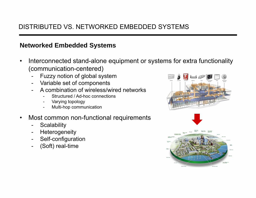
Networked Embedded Systems
• Interconnected stand-alone equipment or systems for extra functionality (communication-centered)- Fuzzy notion of global system - Variable set of components- A combination of wireless/wired networks
- Structured / Ad-hoc connections- Varying topology- Multi-hop communication
• Most common non-functional requirements- Scalability- Heterogeneity- Self-configuration- (Soft) real-time
WIRED NETWORKING TECHNOLOGIES FOR EMBEDDED SYSTEMS

WIRELESS NETWORKING TECHNOLOGIES FOR EMBEDDED SYSTEMS

PERFORMANCE TRADEOFF: RF WIRELESS DATA RATES & RANGES
Range
Peak
Dat
a R
ate
(Per
form
ance
)
Closer Farther
Slow
erFa
ster
UWB Wireless Data ApplicationsWireless Data Applications
Wireless Video Applications
Wireless Video Applications
802.11g/n
802.11b
802.11a
2.5G/3G
Bluetooth™
ZigBee™Low Data-Rate
TransferLow Data-Rate
Transfer
Wireless Sensor Networking
Wireless Sensor Networking
Wi-Fi®
Cellular
3G/4G BB
4G
Sub-GHz Sensors
WSNLow-Power(Long Battery Life
Low Cost)
Smart Converged Gateway
Low-Power (Long Battery Life,
Medium Cost)
WAN
WLAN
WSN (PAN) Mesh Network
High-Power (High Cost)
Medium-Power (Low- Cost)
/ACMedium Power
(Medium Cost)
BT (LE)
NFC RFID

A COMPARISON OF WIRELESS NETWORKING TECHNOLOGIES
NETWORK PROPERTIES
• Supported topologies - star, line, tree, mesh, bus, ring…
• Media access mechanisms - controlled access vs. uncontrolled access
• Network performance metrics- Bandwidth, throughput and goodput
• Network real-time performance - latency, jitter, coherent notion of time
• Network Security - Cryptosecurity, Transmission and Physical security

SUPPORTED NETWORK TOPOLOGIES
• A ring network: each node is connected to its left and right neighbor node, such that all nodes are connected and that each node can reach each other node by traversing nodes left- or rightwards.
• A mesh network: each node is connected to an arbitrary number of neighbors in such a way that there is at least one traversal from any node to any other.
• A star network: all nodes are connected to a special central node. • A fully connected network: each node is connected to every other node in the network.• A tree network: nodes are arranged hierarchically.• A bus network: all nodes are connected to a common medium along this medium.

NETWORK ACCESS: CONTROLLED VS. UNCONTROLLED ACCESS
Three broad classes:
• Channel partitioning, by time, frequency or code- Divide channel into smaller “pieces” (time slots, frequency, code) - Allocate piece to node for exclusive use- Time Division (TDMA), Frequency Division (FDMA), Code Division (CDMA)…
• Random access (dynamic) - Channel not divided, allow collisions- “Recover” from collisions- ALOHA, Slotted ALOHA, CSMA, CSMA/CD- Carrier sensing: easy in some technologies (wire), hard in others (wireless)- CSMA/CD used in Ethernet, and CSMA/CA used in 802.11
• Taking turns- Nodes take turns, but nodes with more to send can take longer turns- polling from central site, token passing- bluetooth, FDDI, token ring

PERFORMANCE METRICS
• Bandwidth is the maximum rate that information can be transferred in bits/second.
• Throughput is the actual rate that information is transferred.- The maximum possible throughput is determined by the available channel
bandwidth and achievable signal-to-noise ratio.- It is not generally possible to send more data than dictated by the Shannon-Hartley
Theorem.
• Goodput is the application level throughput, i.e. the actuate rate that useful information is transferred over a communication channel.
- The amount of information considered excludes protocol overhead bits as well as retransmitted information.
- Goodput is always lower than the throughput.

PERFORMANCE METRICS (CONT.)
• Latency is the delay between the sender and the receiver decoding it- Four sources of delay: nodal processing, transmission delay, propagation delay, and
queueing delay at the intermediate nodes (packet switched networks). - Real-time messages must be transmitted within precise time-bounds.
• Jitter is the variation in delay at the receiver of the information
• Error rate is the number of corrupted bits expressed as a percentage or fraction of the total sent
- Mainly due to noise, interference, distortion or bit synchronization errors
• Interplay of factors: All of the factors above, coupled with user requirements and user perceptions, play a role in determining the perceived “fastness” or utility, of a network connection.

COHERENT NOTION OF TIME ACROSS A NETWORK
• In a distributed (embedded) system, each node has its own clock- Without specific support, there is no explicit coherent notion of time across a
distributed systems.- Worse, due to time drift, clocks tend to permanently diverge.
• A coherent notion of time is important for many applications to:- Carry out actions at desired time instants, e.g. synchronous data acquisition,
synchronous actuation.- Time-stamp data and events.- Compute the age of data.- Coordinate transmissions, e.g. TDMA clock-based systems.
• Clock synchronization can be achieved through:- Externally – an external source sends a time update regularly (e.g. GPS).- Internally – nodes exchange messages to come up with a global clock.
- Master-Slave – The time master spreads its own clock to all other nodes.- Distributed – All nodes perform a similar role and agree on a common clock.
- Uncertainties in network delay will lead to limitations in the achievable precision.

Outline
• Introduction to Networked Embedded Systems- Embedded systems ➜ Networked embedded systems ➜ Embedded Internet- Network properties
• Layered Network Architectures- OSI framework – descriptions of layers- Internet protocol stack
• Physical Layer Options- Guided transmission media- Wireless transmission media
• Data Link Layer Services and MAC Protocols• Embedded System Communication Protocols
- Wired protocols: Ethernet, CAN, TTP, BACnet- Wireless protocols: Wi-Fi, ZigBee, WirelessHART
• TCP/IP Stack and 6LoWPAN Stack • Modeling and Analysis of Communication Protocols

NETWORK ARCHITECTURE
Networks are complex, with many “pieces”:
• End nodes
• Relays (routers)
• Heterogeneous links of various media
• Different applications and user requirements
• Protocols
• Hardware, software
Question: is there any hope of organizing structure of network?
mobile network
global ISP
regional ISPhome
network
institutionalnetwork
LAYER ARCHITECTURE
• Layer architecture simplifies the network design.- Explicit structure allows identification, relationship of complex system’s pieces.- Modularization eases maintenance, updating of system.- Change of implementation of layer’s service transparent to rest of system.
• It is easy to debug network applications with a layered architecture.
• The network management is easier due to the layered architecture.
• Network layers follow a set of rules, called protocol.
• The protocol defines the format of the data being exchanged, and thecontrol and timing for the handshake between layers.
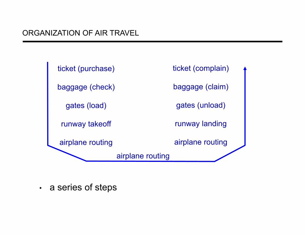
ORGANIZATION OF AIR TRAVEL
• a series of steps
ticket (purchase)
baggage (check)
gates (load)
runway takeoff
airplane routing
ticket (complain)
baggage (claim)
gates (unload)
runway landing
airplane routing
airplane routing

ticket (purchase)
baggage (check)
gates (load)
runway (takeoff)
airplane routing
departureairport
arrivalairport
intermediate air-trafficcontrol centers
airplane routing airplane routing
ticket (complain)
baggage (claim
gates (unload)
runway (land)
airplane routing
ticket
baggage
gate
takeoff/landing
airplane routing
LAYERING OF AIRLINE FUNCTIONALITY
layers: each layer implements a service• via its own internal-layer actions
• relying on services provided by layer below
WHY LAYERING CONSIDERED HARMFUL?
Structured layering implies that the functions of each layer are carried out completely before the protocol data unit is passed to the next layer.
This means that the optimization of each layer has to be done separately.
Such ordering constraints are in conflict with efficient implementation of data manipulation functions.

OPEN SYSTEMS INTERCONNECTION (OSI) MODEL
• International standard organization (ISO) established a committee in 1977 to develop an architecture for computer communication.- In 1984, the Open Systems Interconnection (OSI) reference model was
approved as an international standard for communications architecture.- The OSI model is now considered the primary Architectural model for
inter-computer communications.
• Term “open” denotes the ability to connect any two systems which conform to the reference model and associated standards.
• The OSI reference model divides the problem of moving information between computers over a network medium into SEVEN smaller and more manageable problems.
• This separation into smaller more manageable functions is known as layering.

ISO/OSI REFERENCE MODEL
application
presentation
session
transport
network
link
physical
• Application: Network processes to applications- FTP, SMTP, HTTP…
• Presentation: Data representation- encryption, compression, machine-specific conventions
• Session: Interhost communication
- synchronization, checkpointing, recovery of data exchange
• Transport: End-to-end connections- TCP, UDP
• Network: Addressing and routing- IP, routing protocols
• Link: Access to media- Ethernet, 802.111 (WiFi), PPP
• Physical: bits “on the wire”

OSI: A LAYERED NETWORK MODEL
• The process of breaking up the functions or tasks of networking into layers reduces complexity.
• Each layer provides a service to the layer above it in the protocol specification.
• Each layer communicates with the same layer’s software or hardware on other computers.
• The lower 4 layers (transport, network, data link and physical layers) are concerned with the flow of data from end to end through the network.
• The upper three layers (application, presentation and session) are orientated more toward services to the applications.
• Data is encapsulated with the necessary protocol information as it moves down the layers before network transit.

OSI REFERENCE MODEL: PHYSICAL LAYER
• Provides physical interface for transmission of information.• Defines rules by which bits are passed from one system to another on
a physical communication medium.• Covers all - mechanical, electrical, functional and procedural -
aspects for physical communication.• Such characteristics as voltage levels, timing of voltage changes,
physical data rates, maximum transmission distances, physical connectors, and other similar attributes are defined by physical layer specifications.
Issues related with the physical layer: interconnection topology, physical medium, coding of digital information, transmission rate, maximum interconnection length, max number of nodes, feeding power through the network, energy consumption…

OSI REFERENCE MODEL: DATA LINK LAYER
• Data link layer attempts to provide reliable communication over the physical layer interface.
• Breaks the outgoing data into frames and reassemble the received frames.
• Create and detect frame boundaries.• Handle errors by implementing an acknowledgement and
retransmission scheme.• Implement flow control.• Supports points-to-point as well as broadcast communication.• Supports simplex, half-duplex or full-duplex communication.
Issues related with the data link layer: addressing, logical link control (flow control, transmission error control), medium access control…

OSI REFERENCE MODEL: NETWORK LAYER
• Implements routing of frames (packets) through the network.• Defines the most optimum path the packet should take from the
source to the destination.• Defines logical addressing so that any endpoint can be identified. • Handles congestion in the network.• Facilitates interconnection between heterogeneous networks
(Internetworking).• The network layer also defines how to fragment a packet into smaller
packets to accommodate different media.
Issues related with the network layer: logical addressing, routing…

OSI REFERENCE MODEL: TRANSPORT LAYER
• Purpose of this layer is to provide a reliable mechanism for the exchange of data between two processes in different computers.
• Ensures that the data units are delivered error free.• Ensures that data units are delivered in sequence.• Ensures that there is no loss or duplication of data units.• Provides connectionless or connection oriented service.• Provides for the connection management.• Multiplex multiple connection over a single channel.
Issues related with the transport layer: reliable data transfer, multiplexing and demultiplexing, connection management…

OSI REFERENCE MODEL: SESSION LAYER
• Session layer provides mechanism for controlling the dialogue between the two end systems. It defines how to start, control and end conversations (called sessions) between applications.
• This layer requests for a logical connection to be established on an end-user’s request.
• Any necessary log-on or password validation is also handled by this layer.
• Session layer is also responsible for terminating the connection.• This layer provides services like dialogue discipline which can be full
duplex or half duplex.• Session layer can also provide check-pointing mechanism such that if
a failure of some sort occurs between checkpoints, all data can be retransmitted from the last checkpoint.
OSI REFERENCE MODEL: PRESENTATION AND APPLICATION LAYER
Presentation layer• Presentation layer defines the format in which the data is to be
exchanged between the two communicating entities. • Also handles data compression and data encryption (cryptography).
Application layer• Application layer interacts with application programs and is the
highest level of OSI model.• Application layer contains management functions to support
distributed applications.• Examples of application layer are applications such as file transfer,
electronic mail, remote login etc.

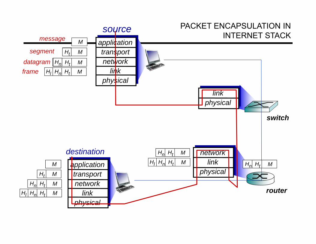
INTERNET PROTOCOL STACK
• Internet stack “missing” presentation and session layers.
- These services, if needed, must be implemented in applications.
• Application: supporting network applications- FTP, SMTP, HTTP
• Transport: process data transfer- TCP, UDP
• Network: routing of datagrams from source to destination- IP, routing protocols
• Link: data transfer between neighboring network elements- Ethernet, 802.111 (WiFi), PPP
• Physical: bits “on the wire”
application
transport
network
link
physical
sourceapplicationtransportnetwork
linkphysical
HtHn M
segment Ht
datagram
destinationapplicationtransportnetwork
linkphysical
HtHnHl M
HtHn M
Ht M
M
networklink
physical
linkphysical
HtHnHl M
HtHn M
HtHn M
HtHnHl M
router
switch
PACKET ENCAPSULATION IN INTERNET STACK message M
Ht M
Hn
frame

EMBEDDED / REAL-TIME PROTOCOL STACK
• The OSI 7 layers impose a considerable overhead- Time to execute the protocol stack- Time to transmit protocol control information- Memory requirements (for all intermediate protocol invocations)
• Many embedded / real-time networks- are dedicated to a well defined application- use single broadcast domain (no need for routing)- use short messages (no need to fragment/reassemble)
Figure from Dr. Luis Almeida

Outline
• Introduction to Networked Embedded Systems- Embedded systems ➜ Networked embedded systems ➜ Embedded Internet- Network properties
• Layered Network Architectures- OSI framework – descriptions of layers- Internet protocol stack
• Physical Layer Options- Guided transmission media- Wireless transmission media
• Data Link Layer Services and MAC Protocols• Embedded System Communication Protocols
- Wired protocols: Ethernet, CAN, TTP, BACnet- Wireless protocols: Wi-Fi, ZigBee, WirelessHART
• TCP/IP Stack and 6LoWPAN Stack • Modeling and Analysis of Communication Protocols

GUIDED TRANSMISSION MEDIA
Magnetic Media
• HP Ultrium tape =100GB. A box 60x60x60 holds 2000 tapes =>200 Tera bytes=1600 Tbits.
• A box can be delivered in 24 hours anywhere in USA => throughput: 1600 Tbits/86400 sec = 19 Gbps!
Twisted Pair/ Unshielded TP (UTP)
• Classic telephone lines- Category 3 (a) – 16MHz- Category 5 (b) – 100 MHz- Category 6 – 250 MHz- Category 7 – 600 MHz
• Throughput : a few Mbit/sec – Gbits/sec.
• Works up to 100m, afterwards repeaters needed.

GUIDED TRANSMISSION MEDIA (CONT.)
Coaxial Cable• Bandwidth ~ 1 GHz (better shielding)• Up to 200m
Fiber Optics• Rather used at higher bandwidths• Invulnerable to electric and
electromagnetic signals• Could be very long• Hard to tamper with -> Security• Usually simplex transmission
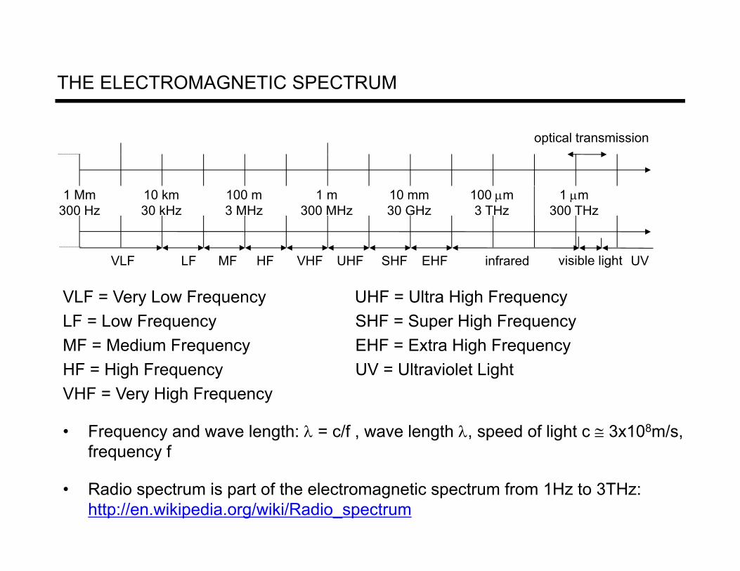
THE ELECTROMAGNETIC SPECTRUM
VLF = Very Low Frequency UHF = Ultra High FrequencyLF = Low Frequency SHF = Super High FrequencyMF = Medium Frequency EHF = Extra High FrequencyHF = High Frequency UV = Ultraviolet LightVHF = Very High Frequency
• Frequency and wave length: = c/f , wave length , speed of light c 3x10⁸m/s, frequency f
• Radio spectrum is part of the electromagnetic spectrum from 1Hz to 3THz: http://en.wikipedia.org/wiki/Radio_spectrum
1 Mm300 Hz
10 km30 kHz
100 m3 MHz
1 m300 MHz
10 mm30 GHz
100 m3 THz
1 m300 THz
visible lightVLF LF MF HF VHF UHF SHF EHF infrared UV
optical transmission

• ITU (International Telecommunication Union)-R holds auctions for new frequencies, manages frequency bands worldwide (WRC, World Radio Conferences) Europe US A Japan
Cellular Phones
G SM 450-457, 479-486/460-467,489-496, 890-915/935-960, 1710-1785/1805-1880 UM TS (FDD) 1920-1980, 2110-2190 UM TS (TDD) 1900-1920, 2020-2025
AM PS , TDM A , CDM A 824-849, 869-894 TDM A , CDM A , G SM 1850-1910, 1930-1990
PDC 810-826, 940-956, 1429-1465, 1477-1513
Cordless Phones
CT1+ 885-887, 930-932 CT2 864-868 DECT 1880-1900
PACS 1850-1910, 1930-1990 PACS-U B 1910-1930
PHS 1895-1918 JCT 254-380
W ireless LANs
IEEE 802.11 2400-2483 HIPERLAN 2 5150-5350, 5470-5725
902-928 IEEE 802.11 2400-2483 5150-5350, 5725-5825
IEEE 802.11 2471-2497 5150-5250
O thers RF-Control 27, 128, 418, 433, 868
RF-Control 315, 915
RF-Control 426, 868
FREQUENCIES AND REGULATIONS