leaving certificate 2008 marking scheme construction ... ol ms_1.pdf · marking scheme construction...
TRANSCRIPT

Coimisiún na Scrúduithe StáitState Examinations Commission
LEAVING CERTIFICATE 2008
MARKING SCHEME
CONSTRUCTION STUDIES
ORDINARY LEVEL


LEAVING CERTIFICATE 2008
MARKING SCHEME
CONSTRUCTION STUDIES
ORDINARY LEVEL

1
Ceist 1 Part (a)
• Concrete tiles • Softwood battens 44 x 35 mm • Roofing felt • Rafters 150 x 50 mm • Roof insulation to comply with current
Building Regulations • Ceiling joists 150 x 50 mm • 12.5 mm foil-backed plasterboard
ceiling with skim coat • Wallplate 100 x 75 mm tied to
blockwork with holding down straps
• Concrete block inner leaf 100 mm • 15 mm internal plaster • Insulation to comply with current
Building Regulations • Residual cavity 40 mm • Concrete block outer leaf 100 mm • 19 mm external render • Soffit 12 mm • Fascia 25 mm • Gutter 100 mm
Alternative detailing which complies with current Building Regulations acceptable. Part (b) Method of providing ventilation to the roof members
• Vents are provide in the soffit • Proprietary tile ventilators are used near the eaves where soffit ventilation is not possible • Proprietary eaves ventilators are fixed between the rafters.

2
Ceist 2 Part (a) Construction of foundations
• All foundations to conform to current Buildings Regulations • A mechanical excavator used to excavate the trenches • Occasionally hand tools are used in small or confined foundations • Levels at the bottom of trenches are constantly checked using spirit levels, laser levels or
Theodolite and levelling staff. • All loose soil is removed from the trenches • Wooden or steel pegs are driven at approximately two metre intervals • The pegs must be a minimum of 300 mm above the bottom of the trench as this gives an
accurate depth for the concrete • Reinforcing steel or steel mesh is tied
and laid on concrete bricks which keep the steel 75 mm above the base of the foundation
• Ready-mixed concrete is poured around the steel in the trenches
• The concrete is levelled in line with the pegs using a screed or straight edge
• Screeding must be completed within two to three hours before the concrete starts to set
• The foundations should be left for seven to ten days in order for the concrete to set properly.
Depth of trench
• The depth “D” of foundation must be as deep as necessary for the type of ground • Minimum depth of foundation excavation below finished ground level should be 600 mm. • The bottom of the trench must be below the frost line as freezing and thawing causes
problems for foundations. Generally for clay soil the depth is usually one metre.

3
Width of foundation • The minimum width “W” of foundation must
be three times the wall thickness “W.T”. • For a 300 mm wall the minimum is 900 mm.
Thickness of foundation
• The minimum concrete thickness “T” should be not less than 300 mm
Position of a 300 mm wall on the foundation
• Walls must be built in the centre of the foundation
• The projections “P” on both sides must be equal
Part (b) Design detail
• The projection “P” should be less than the thickness “T” or at most be equal to “T” to avoid shear failure
• Reinforcing concrete with steel makes a very good composite material ideal for foundations
• The concrete takes the compressive strength and the steel takes the tensile strength
• Three steel rods diameter 12 mm generally used Sketch shows foundations without reinforcing and consequent shear
• Steel mesh may also be used • The steel is placed near the bottom of the concrete where the main tensile strength is needed • The concrete is poured and compacted around the reinforcing steel

4
Ceist 3 Part (a)
• Stop valve • Drain off valve • To kitchen sink • 12 mm rising main • Ballvalve • Cold water storage tank 230 litres min
• Insulation around storage tank and pipes
• 28 mm overflow • Gate valve • 15 mm cold water supply • Connection to wash hand basin • Connection to WC.
Alternative detailing which complies with current Building Regulations is acceptable. Part (b) How the level of water is controlled in the cistern of the WC
• The level of water in the cistern falls when the toilet is flushed
• The ball or float (A) drops as the level of water falls • The valve (B) opens and water enters the cistern
through the valve • The ball or float rises as the level of water increases • The valve closes and stops the water entering the
cistern • This brings the water to the same level each time.
5
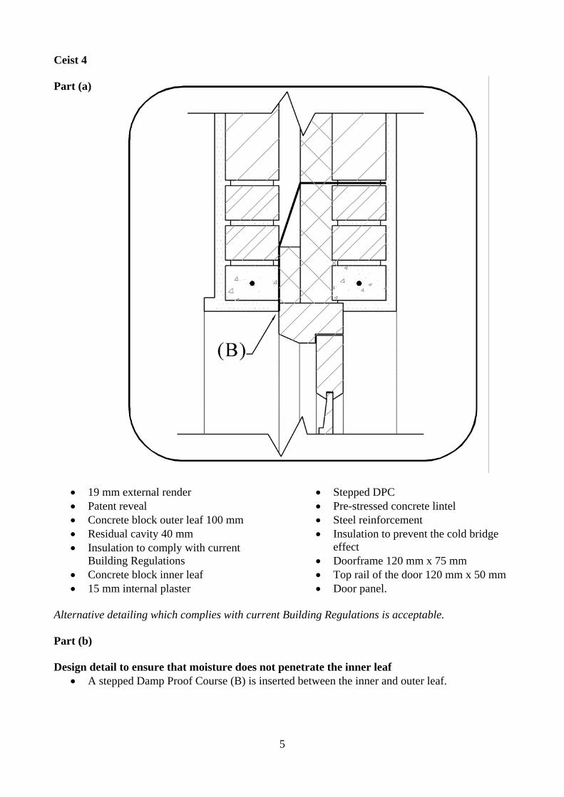
Ceist 4 Part (a)
• 19 mm external render • Patent reveal • Concrete block outer leaf 100 mm • Residual cavity 40 mm • Insulation to comply with current
Building Regulations • Concrete block inner leaf • 15 mm internal plaster
• Stepped DPC • Pre-stressed concrete lintel • Steel reinforcement • Insulation to prevent the cold bridge
effect • Doorframe 120 mm x 75 mm • Top rail of the door 120 mm x 50 mm • Door panel.
Alternative detailing which complies with current Building Regulations is acceptable. Part (b) Design detail to ensure that moisture does not penetrate the inner leaf
• A stepped Damp Proof Course (B) is inserted between the inner and outer leaf.

6
Ceist 5 Part (a) Reasons for planning permission
• Planning permission is a legal requirement • Planning permission informs the public about development • It regulates all new building work • It controls the height, shape, design and location of buildings • It prevents the danger of unsafe buildings • Proper regulation of sewage and waste disposal • Ensures that buildings are attractive and environmentally friendly • Ensures that buildings blend easily with their surroundings.
Part (b) Outline Planning Permission
• Outline permission is used to establish if the planning authority will agree to the development
• It is a general permission for the site • This is not concerned with the exact technical detailing of the development • Detailed drawings are not needed • This permission does not allow the development to proceed.
Examples of a situation where a person would use outline planning permission
• If a person or company is interested in the development of a site for building purposes • Outline planning increases the value of the property • Less documentation and less expense involved • No detailed plans needed • Application for outline permission gives a person an indication of how the planning
authority will approach the development. • Will find out if planning authorities have any difficulties with development – heritage, road
access, visual impact, percolation areas and proximity to other buildings… Part (c) Reasons for refusal
• The application does not comply with the development plan for the area • No prior consultation has been made with the planning authority • The proposed building will not blend in with existing built and natural environment • Once off development is not allowed on this site • Proper sewage treatment is not available • The site is not suitable for a private sewage treatment facility • The road is not suitable for extra traffic • The entrance could be unsafe for traffic and residents.

7
Ceist 6 Part (a) Rigid insulation board in the cavity of an external wall of concrete block construction
• The rigid insulation is fitted against the inner leaf of the cavity wall • The residual cavity is 40 mm • The typical thickness of the insulation is 60mm.
Part (b) Show how the insulation board is held in place
• The insulation board is held in place using specially designed wall ties
• The wall ties hold the board tight against the wall • The insulation boards are joined together using a tongue and groove
system. Part (c) Another method of insulating external walls
• Dry lining could be fitted to the inner face of the external walls • This consists of treated softwood battens 50 x 25 mm with insulation in between • Plasterboard of 12 mm thickness is fitted to the battens • Insulated dry lining plasterboard may also be used • Special insulation may be pumped into the cavity of existing walls • The insulation may also be pumped into the cavity of new walls • Insulation could be fitted to the outside surface of external walls.

8
Ceist 7 Part (a) Safety precautions to be observed when using a pillar drill
• Ensure the work is held securely • Wear eye protection • No loose clothing • Set the correct speed • Ensure the guard is in place at all times • Use the correct drill bit for the work being carried out.
Safety precautions to be observed when fitting a double glazed unit in a wooden window frame
• Be mindful of the sharp edges on the panel • Use gloves to protect hands • Wear a hard hat • Wear steel toe capped boots • Use suction pads where needed • Use a suitable bedding sealant • Use correct scaffolding where necessary • Get help if installing a large panel.
Safety precautions to be observed when using contact glue to fix veneer to a wooden panel
• Carry out the work in a well ventilated area • Keep the glue away from sources of ignition • Wear a mask and gloves • Read the instructions on the container • Do not inhale the fumes • Avoid contact with the skin • Keep out of the reach of children.
Part (b) Hard hat
• Must be worn by workers and visitors to the building site • Hard hat offers protection from falling objects.
Steel toe capped boots
• Must be worn by workers on the site • These protect the feet when working on a construction site.
High visibility jackets
• These jackets must be worn by all workers and visitors to the site • People are clearly visible on site when using these jackets.

9
Ceist 8 Dovetail joint
• The joint may be a tee dovetail halving or box dovetail • This joint is widely used in woodwork • The joint is strong and attractive • It may be used in drawer construction • The main parts of a corner dovetail joint are the pins and the tails • The slope or taper for dovetails is important • The slope is 1:6 for softwoods • The slope is 1:8 for hardwoods.
Through and through sawing
• This is a method used to convert logs to boards of suitable size
• It is also known as plain sawing or slash sawing • The log is cut straight through to produce the boards • This is a low cost operation with little waste • The boards are likely to cup when being dried • No particular grain pattern is shown.
Damp proof membrane
• This is a plastic sheet spread all over the floor area • It prevents dampness rising up through the floor • The DPM rests on a layer of blinding • The blinding protects the membrane • The DPM is brought up at the edges and over the
internal leaf • The damp proof membrane links with the DPC • The membrane is usually 1200 gauge plastic • The floor insulation rests on the damp proof
membrane.

10
Pre-stressed concrete lintel • This is a ready made concrete lintel and is pre-stressed during manufacture • The lengths vary to suit different door and window openings • The cross section size is 150 x 65 or 100 x 65 • The lintel is manufactured using concrete with a high tensile
steel cable • The cable is stretched in a special mould • Concrete is then poured into the mould around the cable • When the concrete is set the cable is released putting the
concrete in compression Plasterboard
• Plasterboard is used for ceilings partitions and dry lining • The plasterboard is made using gypsum plaster • The plaster is bonded between two sheets of special papers • The board is available in a range of thicknesses but 12mm and
10mm are most commonly used • The sheets vary in size with the common size being 2400 x
1200mm • The edge of the board is finished with square, tapered or
rounded edges • Plasterboard has one ivory and one grey face and this allows for
direct paint or plaster finish • Insulated dry lining plasterboard may also be used.
Gully trap
• This is a PVC fitting used to collect waste water or rainwater • It is placed at the head of a drain • The top is square or round and fitted with a plastic grid • The gully may have a back inlet • The grid prevents leaves and dirt from entering the gully • The gully trap always retains a seal of water • The seal prevents smells coming from the drainage system.
Inspection chamber
• This is used for underground drainage • It is used to gain access to the underground drains • It is used for the cleaning of blockages in the drain system • The chamber may be constructed of brick, block, concrete or
PVC • Inspection chambers are used at the head of the drain, at a
change in direction or for a change of level • The chamber can be used for drains of depth up to 1metre • When the depth exceeds one metre it is called a manhole.

11
Ceist 9 Part (a) Suitable woods for the external cladding
• Cedar • Larch • Red deal or Scots pine • Any pressure impregnated softwood.
Reasons for choice of wood Cedar
• Ideal for outdoor as it is very resistant to decay • Easy to work and glue together • Pleasant appearance • Easily finished with oil or other suitable treatment • It is lightweight making it suitable for cladding.
Larch
• Naturally durable for outdoor use • Looks well with red heartwood • Is easily grown in Ireland • It is resistant to water.
Red deal or Scots pine
• Easy to cut and work • Provides a good finish when painted or varnished • Reasonably priced • Strong durable and stable.
Part (b) Suitable applied finish to help preserve the cladding
• A wide range of oil based finishes is available • These are available from well known manufacturers • They are supplied under the headings such as Deck oil or Fence life • They are available in a range of colours • Water based finishes are also available • Any of these are suitable as an applied finish for the cladding • These finishes will preserve the wood.

12
Steps involved in applying the finish
• Ensure the wood is clean and dry • Sand lightly and clean with white spirits • Apply the finish using a good quality brush • Apply even coats and finish in the direction of the grain • Apply three coats and sand lightly between coats.
Part (c) Design feature that helps protect the cladding from the effects of weather
• The roof projects out to the front • This protects the cladding from sunlight and rain • The gable end or barge of the roof projects out over the gable wall • This design detail helps protect the cladding from the effects of the weather • Lap at the joint of the board - shiplap • Any other suitable design feature.
13
Staidéar Foirgníochta Teoiric – Gnáthleibhéal Scéim Mharcála
Construction Studies Theory – Ordinary Level Marking Scheme
Coimisiún na Scrúduithe Stáit State Examinations Commission

14
Question 1
Details Marks
Concrete tiles 4
Softwood battens 44 x 35 mm 4
Roofing felt 4
Rafters 150 x 50 mm 4
Roof insulation to comply with current Building Regulations 4
Ceiling joists 150 x50 mm 4
12.5 mm foil-backed plasterboard ceiling with skim coat 4
Wallplate 100 x 75 mm 4
15 mm internal plaster 4
Concrete block inner leaf 100 mm 4
Insulation to comply with current Building Regulations 4
Residual cavity 40 mm 4
Concrete block outer leaf 100 mm 4
19 mm external render 4
Soffit board 12 mm 4
Fascia board 25 mm 4
Eave gutter 100 mm 4
Any 9 of the above details (4 marks each) Sub-total 36
Draughting, accuracy and scale (excellent, good, fair) 8
Part (b)
Method of providing ventilation to the roof members 6
Total 50 marks

15
Question 2
Details Marks
Part (a)
Construction of foundations
Valid detail 1 4
Valid detail 2 4
Valid detail 3 4
Valid detail 4 4
Sketches
Depth of trench 4
Width of foundation 4
Thickness of foundation 4
Position of a 300 mm wall on the foundation 4
Quality of sketches (excellent, good, fair) 6
Part (b)
Design detail to ensure that the foundation is strong enough 6
Dimension 1 3
Dimension 2 3
Total 50 marks

16
Question 3
Details Marks
Part (a)
Stop valve 4
Drain off valve 4
Rising main 4
To kitchen sink 4
Ballvalve 4
Cold water storage tank 4
Insulation 4
Overflow 4
Gate valve 4
Cold water supply 4
Connection to wash hand basin 4
Connection to WC 4
Typical sizes 4
Any 9 of the above details (4 marks each) Sub-total 36
Quality of sketch (excellent, good, fair) 6
Part (b)
Primary communication of relevant information 5
Other communication of relevant information 3
Total 50 marks

17
Question 4
Details Marks
Part (a)
19 mm external render 4
Patent reveal 4
Concrete block outer leaf 100 mm 4
Stepped DPC 4
Residual cavity 40 mm 4
Insulation to comply with current Building regulations 4
Concrete block inner leaf 100 mm 4
15 mm Internal plaster 4
Concrete lintel 4
Steel reinforcement 4
Prevention of cold bridge 4
Doorframe 120 mm x 75 mm 4
Top rail of the door 120 mm x 50 mm 4
Door panel 4
Any 9 of the above details (4 marks each) Sub-total 36
Draughting, accuracy and scale (excellent, good, fair) 8
Part (b)
Design detail to ensure that moisture does not penetrate to the inner leaf 6
Total 50 marks
18
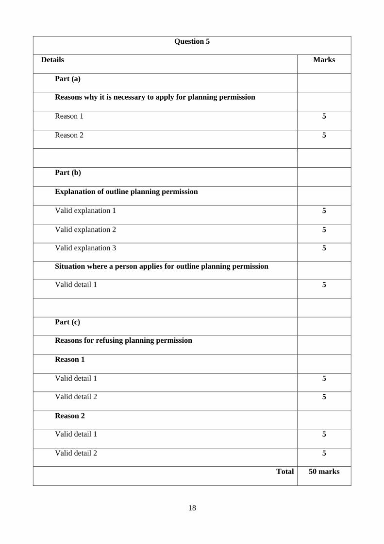
Question 5
Details Marks
Part (a)
Reasons why it is necessary to apply for planning permission
Reason 1 5
Reason 2 5
Part (b)
Explanation of outline planning permission
Valid explanation 1 5
Valid explanation 2 5
Valid explanation 3 5
Situation where a person applies for outline planning permission
Valid detail 1 5
Part (c)
Reasons for refusing planning permission
Reason 1
Valid detail 1 5
Valid detail 2 5
Reason 2
Valid detail 1 5
Valid detail 2 5
Total 50 marks
19
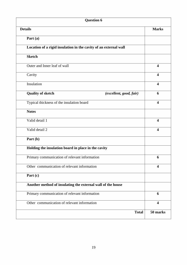
Question 6
Details Marks
Part (a)
Location of a rigid insulation in the cavity of an external wall
Sketch
Outer and Inner leaf of wall 4
Cavity 4
Insulation 4
Quality of sketch (excellent, good, fair) 6
Typical thickness of the insulation board 4
Notes
Valid detail 1 4
Valid detail 2 4
Part (b)
Holding the insulation board in place in the cavity
Primary communication of relevant information 6
Other communication of relevant information 4
Part (c)
Another method of insulating the external wall of the house
Primary communication of relevant information 6
Other communication of relevant information 4
Total 50 marks
20
Question 7
Details Marks
Part (a)
Using a pillar drill in the Construction Studies room
Precaution 1 5
Precaution 2 5
Fitting a double glazed unit in a wooden window frame
Precaution 1 5
Precaution 2 5
Using a contact adhesive to fix veneer to a wooden panel
Precaution 1 5
Precaution 2 5
Part (b)
Safety sign 1
Sketch of sign Quality of sketch - (excellent, good, fair) 6
Purpose of sign 4
Safety sign 2
Sketch of sign Quality of sketch - (excellent, good, fair) 6
Purpose of sign 4
Total 50 marks

21
Question 8
Details Marks
Item number 1
Primary communication of relevant information 6
Other communication of relevant information 4
Item number 2
Primary communication of relevant information 6
Other communication of relevant information 4
Item number 3
Primary communication of relevant information 6
Other communication of relevant information 4
Item number 4
Primary communication of relevant information 6
Other communication of relevant information 4
Item number 5
Primary communication of relevant information 6
Other communication of relevant information 4
Total 50 marks

22
Question 9
Details Marks
Part (a)
Suitable wood 3
Reasons for choice of wood
Valid reason 1 4
Valid reason 2 4
Part (b)
Suitable applied finish 3
Notes - Applying the finish
Stage 1 – Preparation repair and cleaning 4
Stage 2 – Filling and sanding 4
Stage 3 – Brush application of finish 4
Stage 4 – Light sanding and final coat 4
Sketches - Applying the finish
Any suitable sketch 4
Quality of sketch (excellent, good, fair) 6
Part (c)
Design detail to help protect the cladding from the weather
Primary communication of relevant detail 6
Other communication of relevant detail 4
Total 50 marks

LEAVING CERTIFICATE 2008
MARKING SCHEME
CONSTRUCTION STUDIES –
Practical Test

1
Construction Studies 2008 Marking Scheme – Practical Test
Note: The test piece is to be hand produced by candidates without the assistance of machinery – except a battery powered screwdriver which is allowed. Where there is evidence of the use of machinery for a particular procedure a penalty applies. The component is marked out of 50% of the marks available for that procedure.
B MARKING OUT Marks 1 Left side - vertical:
• joints (2 x 2 marks) • slope (1 mark)
5 2 Right side - vertical
• joints (2 x 2 marks) • slope (1 mark)
5 3 Bottom rail
• joints (3 x 2 marks) • slopes to ends (2 x 1 marks)
8 6 Top rail
• tenons (2 x 2 marks) • halving (3 marks)
7 7 Middle vertical
• top halving • bottom halving (2 x 2 marks)
4 Left leg to frame
• notched joint (4 x1 marks) • slopes (4 x1 marks)
8 Right leg to frame
• notched joint (4 x1 marks) • slopes (4 x1 marks)
8
Total 45
A OVERALL ASSEMBLY MARKS 1 Overall quality of assembled artifact 9
2 Dowels located and fitted correctly 4
3 Design and applied shaping of edge • design (4 marks) • shaping (4 marks)
8
Total 21

2
LEGS TO FRAME C PROCESSING Marks 1 Shaping sloped ends (4 x 1 mark) 4 2 Shaping bottom (4 x 1 mark) 4 3 Shaping top - long slope (2 x 1 mark)
• short cuts to notch (2 x 2 marks) • pare trenches (2 x 1 mark)
8 4 Drilling and countersinking screws
( 2 x 2 marks)
4
Total 20
BOTTOM RAIL D PROCESSING Marks 1 Shaping sloped ends (2 x 1 marks) 2 2 Trenches
• Cut and pare (5 x 3 marks)
15
Total 17
TWO SIDES E PROCESSING Marks 1 Shaping sloped ends (2 x 1 mark) 2 2 Two mortices
(2 x 5 marks)
10 3 Two bridles
(2 x 5 marks)
10
Total
22
TOP RAIL F PROCESSING Marks 1 Two end tenons (2 x5 marks) 10 2 Centre trenches (3 x3 marks) 9
Total
19
MIDDLE RAIL G PROCESSING Marks 1 Trench 3 2 Tee-halving
• sawing with grain (2 marks) • sawing across grain (1 mark)
3
Total
6

