lec 4
DESCRIPTION
formingTRANSCRIPT

Continuous casting and hot rolling
• Metal is melted, cast and hot rolled continuously through a series of rolling
mills within the same process.
• Usually for steel sheet production.
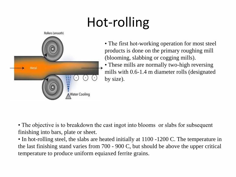
Hot-rolling
• The first hot-working operation for most steel
products is done on the primary roughing mill
(blooming, slabbing or cogging mills).
• These mills are normally two-high reversing
mills with 0.6-1.4 m diameter rolls (designated
by size).
• The objective is to breakdown the cast ingot into blooms or slabs for subsequent
finishing into bars, plate or sheet.
• In hot-rolling steel, the slabs are heated initially at 1100 -1200 C. The temperature in
the last finishing stand varies from 700 - 900 C, but should be above the upper critical
temperature to produce uniform equiaxed ferrite grains.

Cold-rolling
Cold rolling is carried out under
recrystallisation temperature and introduces
work hardening.
• The starting material for cold-rolled steel
sheet is pickled hot-rolled breakdown coil from
the continuous hot-strip mill.
• The total reduction achieved by cold-rolling generally will vary from about
50 %.
• The reduction in each stand should be distributed uniformly without falling much
below the maximum reduction for each pass.
• Generally the lowest percentage reduction is taken place in the last pass to permit
better control of flatness, gage, and surface finish.

Back and front tensions in sheet • The presence of back and front
tensions in the plane of the sheet reduces the
rolling load.
• Back tension may be produced by
controlling the speed of the uncoiler relative to
the roll speed.
• Front tension may be created
by controlling the coiler.
• Back tension is ~ twice as effective in
reducing the rolling load P as front tension.
• If a high enough back tension is applied, the neutral point moves
toward the roll exit
rolls are moving faster than the metal
• If the front tension is used, the neutral point will move toward the
roll entrance.
Back Tension
Front tension
uncoiling Coiling

Problems and defects in rolled products
• Defects from cast ingot before rolling.
Defects other than cracks can result from defects introduced
during the ingot stage of production.
• Porosity, cavity, blow hole occurred in the cast ingot will
be closed up during the rolling process.
• Longitudinal stringers of non-metallic inclusions or
pearlite banding are related to melting and solidification
practices. In severe cases, these defects can lead to
laminations which drastically reduce the strength in the
thickness direction.

• Defects after rolling:
• Flatness
• The roll gap must be perfectly parallel to produce sheets/plates with equal
thickness at both ends.
• The rolling speed is very sensitive to flatness. A difference in elongation of
one part in 10,000 between different locations in the sheet can cause waviness.
Perfectly flat More elongated along edges More elongated in the center
Rolling
Direction

Solutions to flatness problems
• Camber and crown can be used to correct the roll deflection (at only one
value of the roll force). Or use rolling mill equipped with hydraulic jacks to
permit the elastic distortion of the rolls to correct deflection.
(a) (b)
(a) The use of cambered rolls to compensate for roll bending.
(b) Uncambered rolls give variation of thickness.

Possible effects when rolling with insufficient camber
Thicker center means the edges would be plastically elongated more than the center,
normally called long edges.
• This induces the residual stress pattern of compression at the edges and tension
along the centerline.
• This can cause centerline cracking (c), warping (d) or edge wrinkling or crepe-
paper effect or wavy edge (e).

Possible effects when rolls are over-cambered.
• Thicker edges than the center means the center would be plastically
elongated more than the edges, resulting in lateral spread.
•The residual stress pattern is now under compression in the centerline and
tension at the edges (b).
• This may cause edge cracking (c), center splitting (d), centerline
wrinkling (e).

Inhomogeneous Deformation
• Edging can also be caused by inhomogeneous deformation in the thickness direction.
• If only the surface of the work piece is deformed (as in a light reduction on a thick slab), the edges are concaved (a).
• With heavy reduction, the center tends to expand more laterally than the surface to produced barrelled edges (b).
• Alligatoring (c) will occur when lateral spread is greater in the center than the surface (surface in tension, center in compression) and with the presence of metallurgical weakness along the centerline.

Surface defects
• • Surface defects are more easily in rolling due to high surface to volume ratio. Grinding , chipping or descaling of defects on the surface of cast ingots or billets are recommended before being rolled.
• • Laps due to misplace of rolls can cause undesired shapes.
• Roll misplacement
• • Flakes or cooling cracks along edges result in decreased ductility in hot rolling such as blooming of extra coarse grained ingot.
• • Scratches due to tooling and handling.
• • Variation in thickness due to deflection of rolls or rolling speed.

Extrusion
• Extrusion is the process by which a block/billet of metal is reduced in cross
section by forcing it to flow through a die orifice under high pressure.
• In general, extrusion is used to produce
cylindrical bars or hollow tubes or for the
starting stock for drawn rod, cold extrusion
or forged products.
• Most metals are hot extruded due to large
amount of forces required in extrusion.
Complex shape can be extruded from the
more readily extrudable metals such as
aluminium.
* The products obtained are also called extrusion.

Extrusion products
• Typical parts produced by extrusion are trim parts used in automotive and
construction applications, window frame members, railings, aircraft
structural parts.
• Example: Aluminium extrusions are used in commercial and domestic
buildings for window and door frame systems, prefabricated
houses/building structures, roofing and exterior cladding, curtain walling,
shop fronts, etc. Furthermore, extrusions are also used in transport for
airframes, road and rail vehicles and in marine applications.

Classification of extrusion processes
• There are several ways to classify metal extrusion processes;
By Direction Direct and Indirect Extrusion.
By Temperature. Hot and cold Extrusion.
By Equipment. Horizontal and Vertical Extrusion.

Direct Extrusion
Schematic illustration of the direct extrusion process.

Direct Extrusion
Friction increases the extrusion force.
Hollow section is formed using a mandrel.

Indirect Extrusion
Schematic illustration of the indirect extrusion process..

Indirect Extrusion
Metal is forced to flow through the die in an opposite direction to the ram’s motion.
Lower extrusion force as the work billet metal is not moving relative to the container wall.
Comments on Direct Extrusion
• Also called forward extrusion
• As ram approaches die opening, a small portion of
billet remains that cannot be forced through die
opening (dead metal zone…..DMZ)
• This extra portion, called the DMZ, must be separated
from extrudate by cutting it just beyond the die exit
• Starting billet cross section usually round
• Final shape of extrudate is determined by die opening
Comments on Indirect Extrusion
• Also called backward extrusion
• Lower extrusion force as the work billet metal is not moving relative to the container wall.
• Limitations of indirect extrusion are imposed by
– Lower rigidity of hollow ram
– Difficulty in supporting extruded product as it exits die

Variation of Ram Force with ram stroke
Note that in direct extrusion the
ram pressure decreases as the
billet is extruded further
because L decreases, whereas
in indirect extrusion the ram
pressure is not a function of
the billet length.
1- upsetting
2- metal starts to flow
3- extrusion
4- pipe
5- DMZ

Extrusion Die Features
• Low die angle - surface area is large, which increases friction at
die-billet interface
– Higher friction results in larger ram force
• Large die angle - more turbulence in metal flow during reduction
– Turbulence increases ram force required
• Optimum angle depends on work material, billet temperature, and
lubrication

Hydrostatic Extrusion

Hydrostatic Extrusion
Using hydrostatic system to reduce the friction and lower the power
requirement.
Sealing is the major problem.

Cold and Hot Extrusion Cold extrusion
• Cold extrusion is the process done at room temperature or slightly elevated
temperatures. This process can be used for most materials-subject to designing
robust enough tooling that can withstand the stresses created by extrusion.
• Examples of the metals that can be extruded are lead, tin, aluminium alloys, copper,
titanium, molybdenum, vanadium, steel. Examples of parts that are cold extruded
are collapsible tubes, aluminium cans,
• cylinders, gear blanks.
• Advantages
• • No oxidation takes place.
• • Good mechanical properties due to severe cold working as long as the
temperatures created are below the re- crystallization temperature.
• • Good surface finish with the use of proper lubricants.

Cold and Hot Extrusion
• Hot extrusion
• Hot extrusion is done at fairly high temperatures, approximately 50 to 75 %
of the melting point of the metal. The pressures can range from 35-700
MPa .
• • The most commonly used extrusion process is the hot direct process. The
cross-sectional shape of the extrusion is defined by the shape of the die.
• • Due to the high temperatures and pressures and its detrimental effect on
the die life as well as other components, good lubrication is necessary. Oil
and graphite work at lower temperatures, whereas at higher temperatures
glass powder is used.
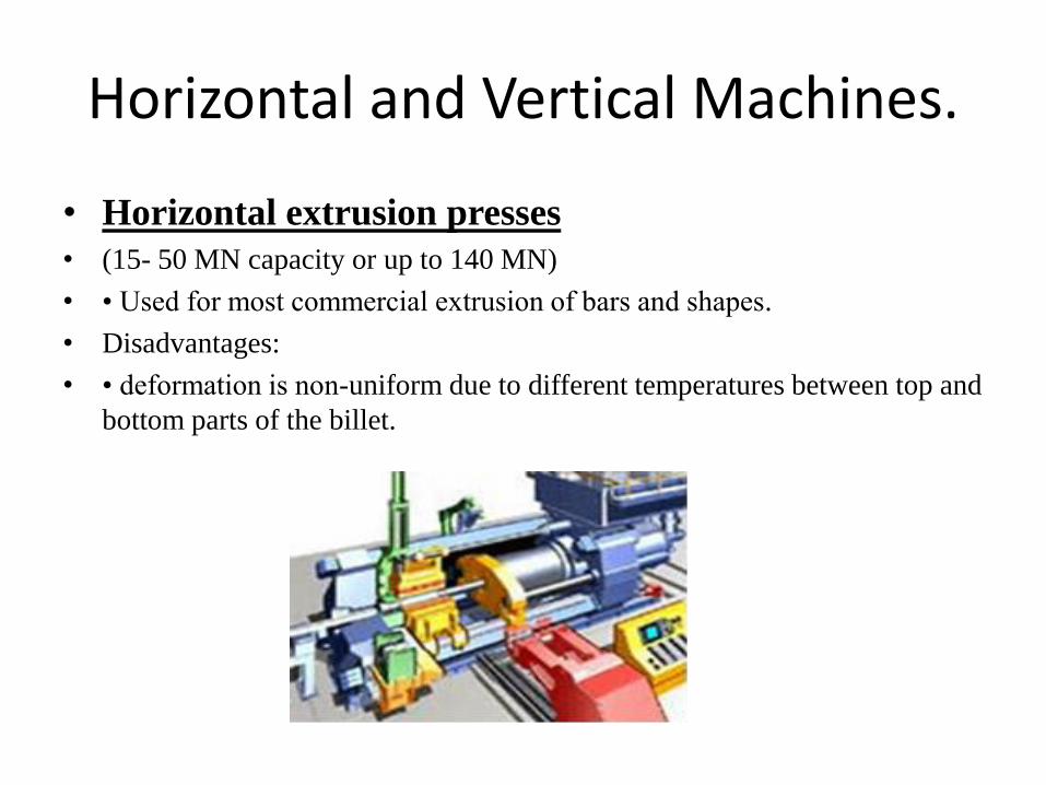
Horizontal and Vertical Machines.
• Horizontal extrusion presses
• (15- 50 MN capacity or up to 140 MN)
• • Used for most commercial extrusion of bars and shapes.
• Disadvantages:
• • deformation is non-uniform due to different temperatures between top and
bottom parts of the billet.
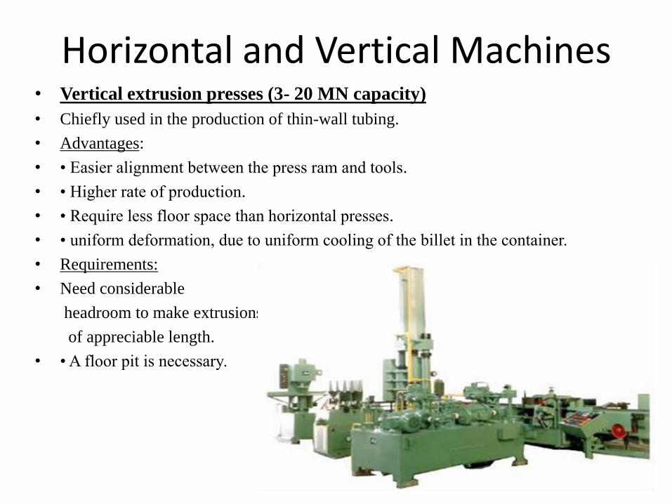
Horizontal and Vertical Machines • Vertical extrusion presses (3- 20 MN capacity)
• Chiefly used in the production of thin-wall tubing.
• Advantages:
• • Easier alignment between the press ram and tools.
• • Higher rate of production.
• • Require less floor space than horizontal presses.
• • uniform deformation, due to uniform cooling of the billet in the container.
• Requirements:
• Need considerable
headroom to make extrusions
of appreciable length.
• • A floor pit is necessary.

Deformation in extrusion, lubrication
• (a) Low container friction and a well-lubricated billet
nearly homogeneous deformation.
• b) Increased container wall
• Friction, producing a dead zone of stagnant
• metal at corners which undergoes little deformation.
• Essentially pure elongation in the center and extensive shear along the sides of the billet. The latter leads to redundant work
c) For high friction at the container-
billet interface, metal flow is concentrated
toward the center and an internal shear plane
develops – due to cold container. In the sticky
friction, the metal will separate internally along
the shear zone. A thin skin will be left in a
container and a new metal surface is obtained.
d) Low container friction and a well
lubricated billet in indirect extrusion.

Dead Metal Zone Dead-Metal Zone-Flowing Metal Interface. The
dead-metal zone occurs when a material is extruded
through square dies. In such geometry, the material in
the corners no longer takes part in the flow but
adheres to the die face, forming a conical die-like
channel through which the billet passes in a still-
converging kind of flow. Friction between
the dead-metal zone and the flowing material is no
more than the shear stress of the material.
Compare between Direct and Indirect Extrusion
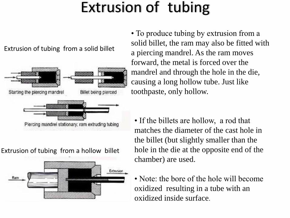
Extrusion of tubing
• To produce tubing by extrusion from a
solid billet, the ram may also be fitted with
a piercing mandrel. As the ram moves
forward, the metal is forced over the
mandrel and through the hole in the die,
causing a long hollow tube. Just like
toothpaste, only hollow.
• If the billets are hollow, a rod that
matches the diameter of the cast hole in
the billet (but slightly smaller than the
hole in the die at the opposite end of the
chamber) are used.
• Note: the bore of the hole will become
oxidized resulting in a tube with an
oxidized inside surface.
Extrusion of tubing from a solid billet
Extrusion of tubing from a hollow billet

Extrusion tubing with a porthole die • The metal is forced to flow into separate
streams and around the central bridge,
which supports a short mandrel.
• The separate streams of metal which
flow through the ports are brought together
in a welding chamber surrounding the
mandrel, and the metal exits from the die
as a tube.
• Since the separate metal streams are
jointed within the die, where there is no
atmosphere contamination, a perfectly
sound weld is obtained.
• Porthole extrusion is used to produce
hollow unsymmetrical shapes in
aluminium alloys.
A sketch of a porthole extrusion die
Porthole extrusion
Example: pyramid porthole dies

Production of seamless pipe and tubing
Extrusion is suited for producing seamless pipe
and tubing, especially for metals which are
difficult to work.
• The red-hot billet is rotated and drawn by
rolls over a piercing rod, or mandrel. The
action of the rolls causes the metal to flow over
and about the mandrel to create a hollow pipe
shell.
• After reheating, the shell is moved forward
over a support bar and is hot- rolled in several
reducing/sizing stands to the desired wall
thickness and diameter.
Stainless steel seamless pipes
Titanium seamless pipes
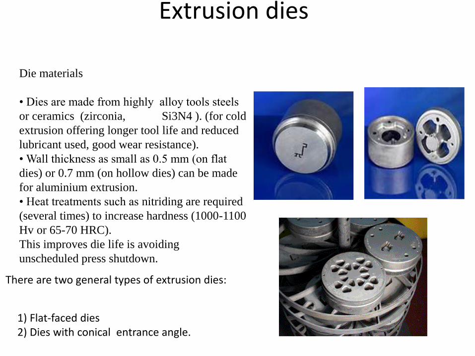
Extrusion dies
Die materials
• Dies are made from highly alloy tools steels
or ceramics (zirconia, Si3N4 ). (for cold
extrusion offering longer tool life and reduced
lubricant used, good wear resistance).
• Wall thickness as small as 0.5 mm (on flat
dies) or 0.7 mm (on hollow dies) can be made
for aluminium extrusion.
• Heat treatments such as nitriding are required
(several times) to increase hardness (1000-1100
Hv or 65-70 HRC).
This improves die life is avoiding
unscheduled press shutdown.
1) Flat-faced dies 2) Dies with conical entrance angle.
There are two general types of extrusion dies:

Extrusion dies
• Metal entering the die will form a dead zone
and shears internally to form its own die angle.
• A parallel land on the exit side of the die helps
strengthen the die and allow for reworking of
the flat face on the entrance side of the die
without increasing the exit diameter.
• requires good lubricants.
• decreasing die angle , increasing
homogeneity, lower extrusion pressure(but
beyond a point the friction in the die surfaces
becomes too great.
• for most operation, 45o < α< 60o
1) Flat-faced dies 2) Dies with conical entrance angle

Schematic illustration of the impact-extrusion process.
The extruded parts are stripped by the use of a stripper
plate, because they tend to stick to the punch.
Impact Extrusion Impact extrusion is performed at higher speeds and shorter strokes
than conventional extrusion.

Sheathing Extrusion was originally applied to the making
of lead pipe and later to the lead sheathing on
electrical cable.
Extrusion of lead sheath on electrical cable.

Effects of temperature on hot extrusion
• Decreased flow stress or deformation resistance due to increasing extrusion
temperature.
• Use minimum temperature to provide metal with suitable plasticity.
• The top working temperature should be safely below the melting point .
• Oxidation of billet and extrusion tools.
• Softening of dies and tools.
• Difficult to provide adequate lubrication.
The temperature of the work piece in metal working depends on;
1) The initial temperature of the tools and the materials
2)Heat generated due to plastic deformation
3)Heat generated by friction at the die/material interface (highest)
4)Heat transfer between the deforming material and the dies and surrounding
environment.

Extrusion Ratio
Also called the reduction ratio, it is defined as
where rx = extrusion ratio; Ao = cross-sectional area of the starting billet; and Af = final cross-sectional area of the extruded section
• Applies to both direct and indirect extrusion
f
ox
A
Ar

Extrusion Analysis
Extrusion ratio, f
ox
A
Ar
Assuming all sections
are circular, ideal
deformation, no friction,
no redundant work:
xrln
Ram pressure
xf rYp ln

Extrusion Analysis
For direct extrusion, additional pressure, pf, required by the extruder to overcome the wall friction is related as follows:
The additional pressure:
The total ram pressure: The power required:
o
fD
LPp
µ4
oD
LPp
µ41
FvP
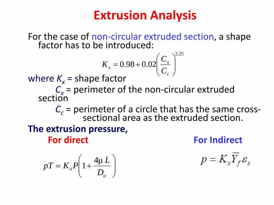
Extrusion Analysis
For the case of non-circular extruded section, a shape factor has to be introduced:
where Kx = shape factor Cx = perimeter of the non-circular extruded
section Cc = perimeter of a circle that has the same cross-
sectional area as the extruded section. The extrusion pressure,
For direct For Indirect
25.2
02.098.0
c
xx
C
CK
o
xD
LPKpT
µ41

Extrusion Defects
a) Centre-burst: internal crack due to excessive tensile stress at the centre possibly because of high die angle, low extrusion ratio.
b) Piping: sink hole at the end of billet under direct extrusion. c) Surface cracking: High part temperature due to low extrusion speed
and high strain rates.