lec10, video i (basics of analog and digital video), v1.03.ppt
TRANSCRIPT
Multimedia SystemsMultimedia Systems
Video IVideo I
(Basics of Analog and Digital Video)(Basics of Analog and Digital Video)
Course PresentationCourse Presentation
(Basics of Analog and Digital Video)(Basics of Analog and Digital Video)
Mahdi Amiri
April 2014
Sharif University of Technology
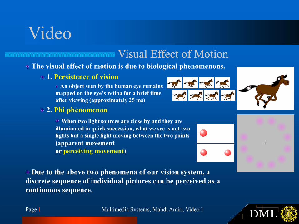
VideoVisual Effect of MotionVisual Effect of Motion
The visual effect of motion is due to biological phenomenons.
1. Persistence of vision
An object seen by the human eye remains
mapped on the eye’s retina for a brief time
after viewing (approximately 25 ms)
2. Phi phenomenon
Multimedia Systems, Mahdi Amiri, Video IPage 1
2. Phi phenomenon
When two light sources are close by and they are
illuminated in quick succession, what we see is not two
lights but a single light moving between the two points
(apparent movement
or perceiving movement)
Due to the above two phenomena of our vision system, a
discrete sequence of individual pictures can be perceived as a
continuous sequence.
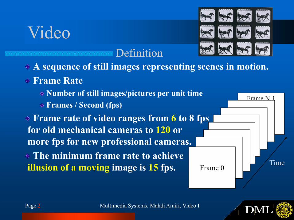
VideoDefinitionDefinition
A sequence of still images representing scenes in motion.
Frame Rate
Number of still images/pictures per unit time
Frames / Second (fps)Frame N-1
Multimedia Systems, Mahdi Amiri, Video IPage 2
Frame rate of video ranges from 6 to 8 fps
for old mechanical cameras to 120 or
more fps for new professional cameras.
The minimum frame rate to achieve
illusion of a moving image is 15 fps. Frame 0TimeTime
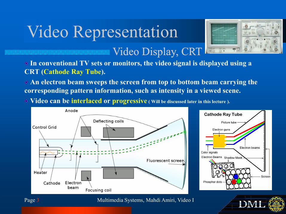
Video RepresentationVideo Display, CRTVideo Display, CRT
In conventional TV sets or monitors, the video signal is displayed using a
CRT (Cathode Ray Tube).
An electron beam sweeps the screen from top to bottom beam carrying the
corresponding pattern information, such as intensity in a viewed scene.
Video can be interlaced or progressive ( Will be discussed later in this lecture ).
Multimedia Systems, Mahdi Amiri, Video IPage 3
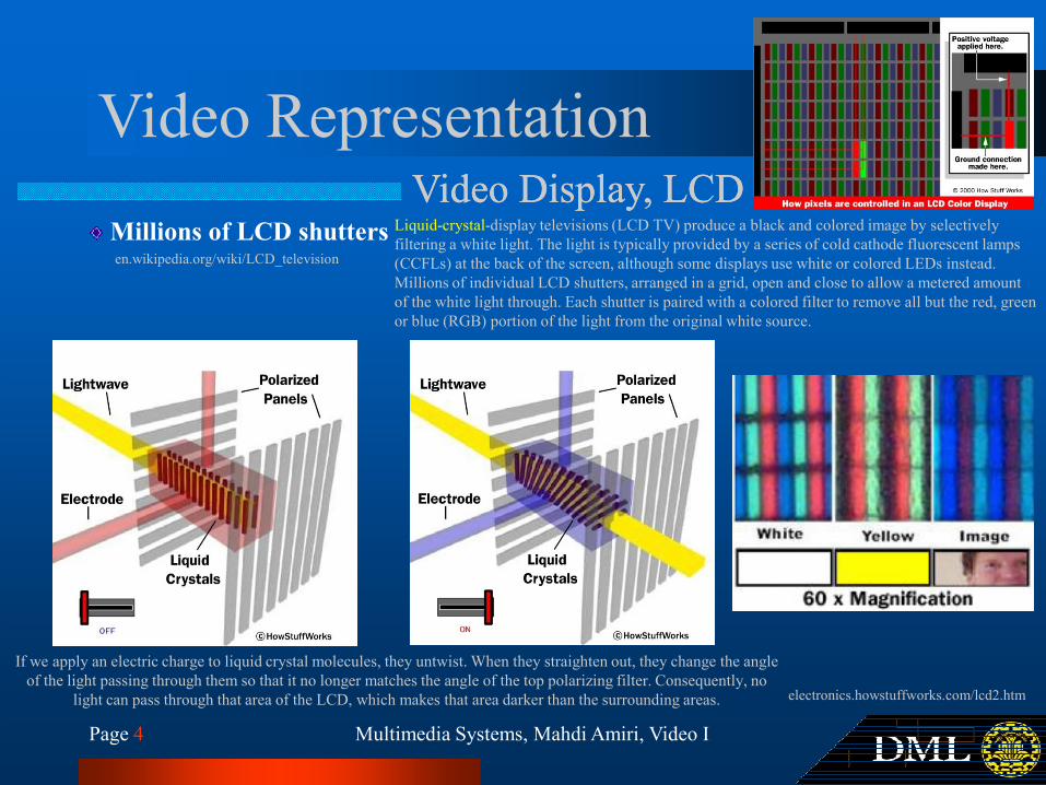
Video RepresentationVideo Display, LCDVideo Display, LCD
Millions of LCD shuttersen.wikipedia.org/wiki/LCD_television
Liquid-crystal-display televisions (LCD TV) produce a black and colored image by selectively
filtering a white light. The light is typically provided by a series of cold cathode fluorescent lamps
(CCFLs) at the back of the screen, although some displays use white or colored LEDs instead.
Millions of individual LCD shutters, arranged in a grid, open and close to allow a metered amount
of the white light through. Each shutter is paired with a colored filter to remove all but the red, green
or blue (RGB) portion of the light from the original white source.
Multimedia Systems, Mahdi Amiri, Video IPage 4
electronics.howstuffworks.com/lcd2.htm
If we apply an electric charge to liquid crystal molecules, they untwist. When they straighten out, they change the angle
of the light passing through them so that it no longer matches the angle of the top polarizing filter. Consequently, no
light can pass through that area of the LCD, which makes that area darker than the surrounding areas.
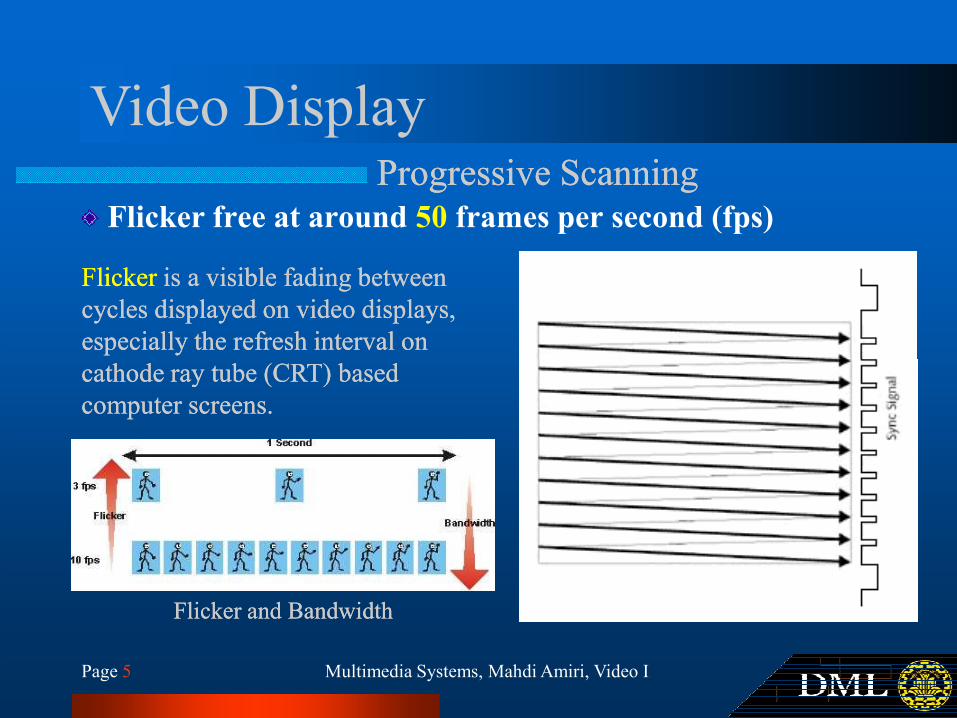
Video DisplayProgressive ScanningProgressive Scanning
Flicker free at around 50 frames per second (fps)
FlickerFlicker is a visible fading between is a visible fading between
cycles displayed on video displays, cycles displayed on video displays,
especially the refresh interval on especially the refresh interval on
cathode ray tube (CRT) based cathode ray tube (CRT) based
Multimedia Systems, Mahdi Amiri, Video IPage 5
cathode ray tube (CRT) based cathode ray tube (CRT) based
computer screens.computer screens.
Flicker and BandwidthFlicker and Bandwidth
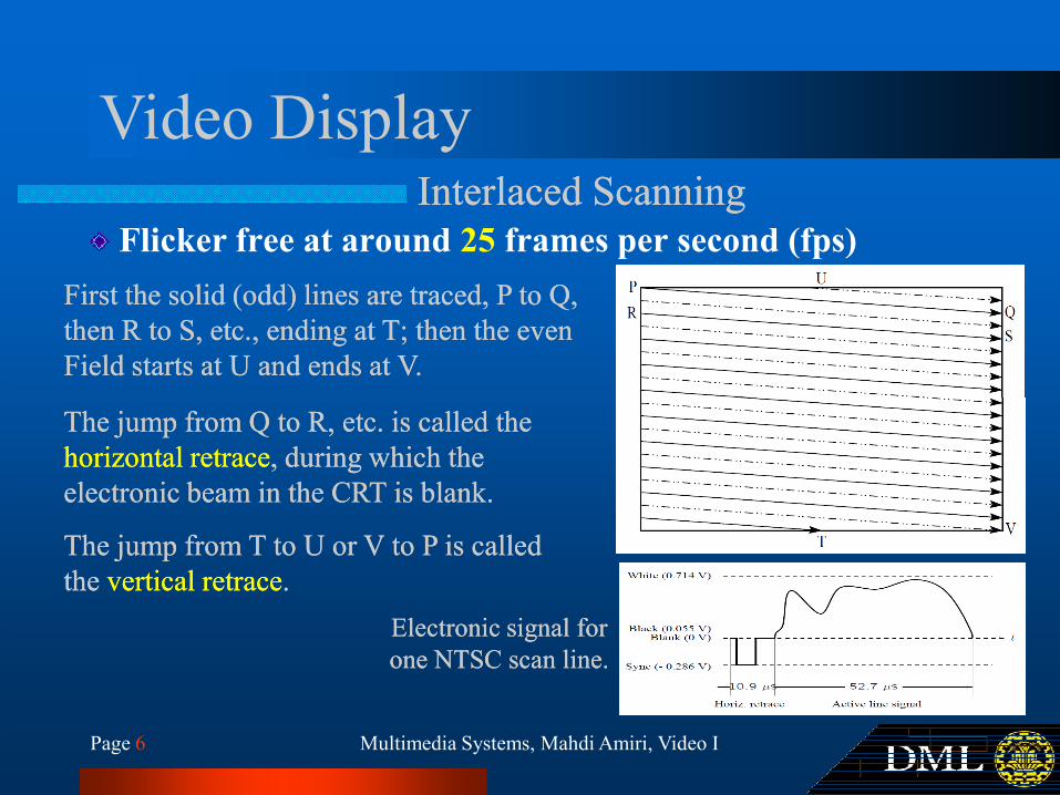
Video DisplayInterlaced ScanningInterlaced Scanning
First the solid (odd) lines are traced, P to Q, First the solid (odd) lines are traced, P to Q,
then R to S, etc., ending at T; then the even then R to S, etc., ending at T; then the even
Field starts at U and ends at V.Field starts at U and ends at V.
Flicker free at around 25 frames per second (fps)
Multimedia Systems, Mahdi Amiri, Video IPage 6
The jump from Q to R, etc. is called the The jump from Q to R, etc. is called the
horizontal retracehorizontal retrace, during which the , during which the
electronic beam in the CRT is blank.electronic beam in the CRT is blank.
The jump from T to U or V to P is called The jump from T to U or V to P is called
the the vertical retracevertical retrace..
Electronic signal for Electronic signal for
one NTSC scan line.one NTSC scan line.
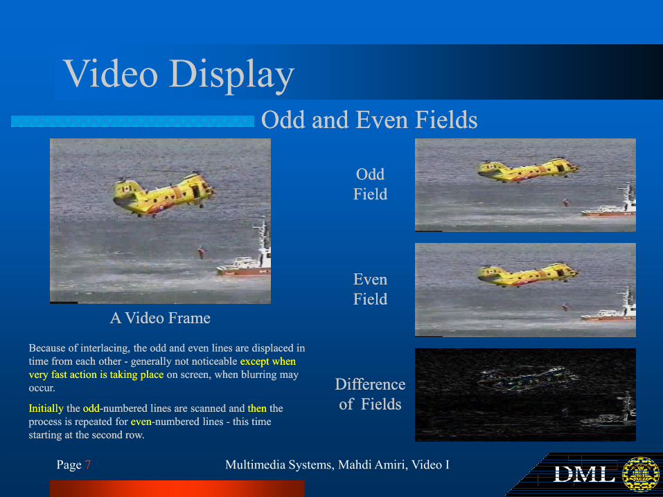
Video DisplayOdd and Even FieldsOdd and Even Fields
OddOdd
FieldField
Multimedia Systems, Mahdi Amiri, Video IPage 7
EvenEven
FieldField
Difference Difference
of Fieldsof Fields
A Video FrameA Video Frame
Because of interlacing, the odd and even lines are displaced in Because of interlacing, the odd and even lines are displaced in
time from each other time from each other -- generally not noticeable generally not noticeable except when except when
very fast action is taking place very fast action is taking place on screen, when blurring may on screen, when blurring may
occur.occur.
InitiallyInitially the the oddodd--numbered lines are scanned and numbered lines are scanned and thenthen the the
process is repeated for process is repeated for eveneven--numbered lines numbered lines -- this time this time
starting at the second row.starting at the second row.
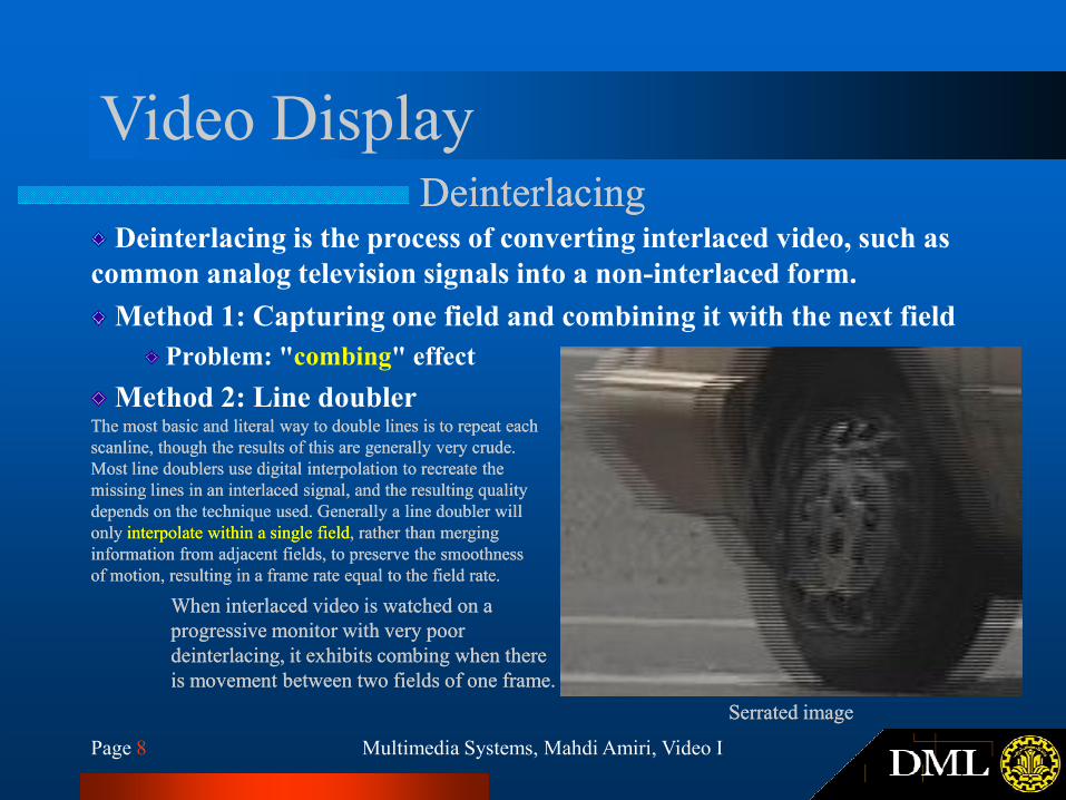
Video DisplayDeinterlacingDeinterlacing
Deinterlacing is the process of converting interlaced video, such as
common analog television signals into a non-interlaced form.
Method 1: Capturing one field and combining it with the next field
Problem: "combing" effect
Method 2: Line doubler
Multimedia Systems, Mahdi Amiri, Video IPage 8
When interlaced video is watched on a When interlaced video is watched on a
progressive monitor with very poor progressive monitor with very poor
deinterlacingdeinterlacing, it exhibits combing when there , it exhibits combing when there
is movement between two fields of one frame.is movement between two fields of one frame.
Method 2: Line doublerThe most basic and literal way to double lines is to repeat each The most basic and literal way to double lines is to repeat each
scanlinescanline, though the results of this are generally very crude. , though the results of this are generally very crude.
Most line doublers use digital interpolation to recreate the Most line doublers use digital interpolation to recreate the
missing lines in an interlaced signal, and the resulting quality missing lines in an interlaced signal, and the resulting quality
depends on the technique used. Generally a line depends on the technique used. Generally a line doublerdoubler will will
only only interpolate within a single fieldinterpolate within a single field, rather than merging , rather than merging
information from adjacent fields, to preserve the smoothness information from adjacent fields, to preserve the smoothness
of motion, resulting in a frame rate equal to the field rate.of motion, resulting in a frame rate equal to the field rate.
Serrated imageSerrated image
Analog Broadcast TV SystemsNTSCNTSC
NTSC (National Television System Committee)
Mostly used in North America and Japan
Aspect Ratio: 4:3
Multimedia Systems, Mahdi Amiri, Video IPage 9
525 scan lines at 30 fps
Interlaced scanning (262.5 lines/field)
Color Space: YIQ
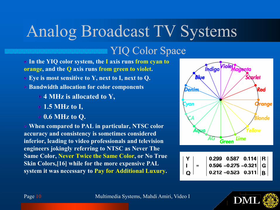
Analog Broadcast TV SystemsYIQ Color SpaceYIQ Color Space
In the YIQ color system, the I axis runs from cyan to
orange, and the Q axis runs from green to violet.
Eye is most sensitive to Y, next to I, next to Q.
Bandwidth allocation for color components
4 MHz is allocated to Y,
1.5 MHz to I,
Multimedia Systems, Mahdi Amiri, Video IPage 10
1.5 MHz to I,
0.6 MHz to Q.
When compared to PAL in particular, NTSC color
accuracy and consistency is sometimes considered
inferior, leading to video professionals and television
engineers jokingly referring to NTSC as Never The
Same Color, Never Twice the Same Color, or No True
Skin Colors,[16] while for the more expensive PAL
system it was necessary to Pay for Additional Luxury.
Analog Broadcast TV SystemsPALPAL
PAL (Phase Alternating Line)
Mostly used in Western Europe, China and India
Aspect Ratio: 4:3
625 scan lines at 25 fps
Multimedia Systems, Mahdi Amiri, Video IPage 11
625 scan lines at 25 fps
Interlaced scanning (312.5 lines/field)
Color Space: YUV
5.5 MHz is allocated to Y, 1.8 MHz each to U and V.
Analog Broadcast TV SystemsSupplementary MaterialsSupplementary Materials
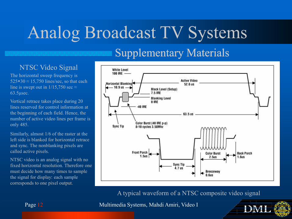
The horizontal sweep frequency is
525×30 ≈ 15,750 lines/sec, so that each
line is swept out in 1/15,750 sec ≈
63.5µsec.
Vertical retrace takes place during 20
lines reserved for control information at
NTSC Video Signal
Multimedia Systems, Mahdi Amiri, Video IPage 12
A typical waveform of a NTSC composite video signal
lines reserved for control information at
the beginning of each field. Hence, the
number of active video lines per frame is
only 485.
Similarly, almost 1/6 of the raster at the
left side is blanked for horizontal retrace
and sync. The nonblanking pixels are
called active pixels.
NTSC video is an analog signal with no
fixed horizontal resolution. Therefore one
must decide how many times to sample
the signal for display: each sample
corresponds to one pixel output.
Analog Broadcast TV SystemsSupplementary MaterialsSupplementary Materials
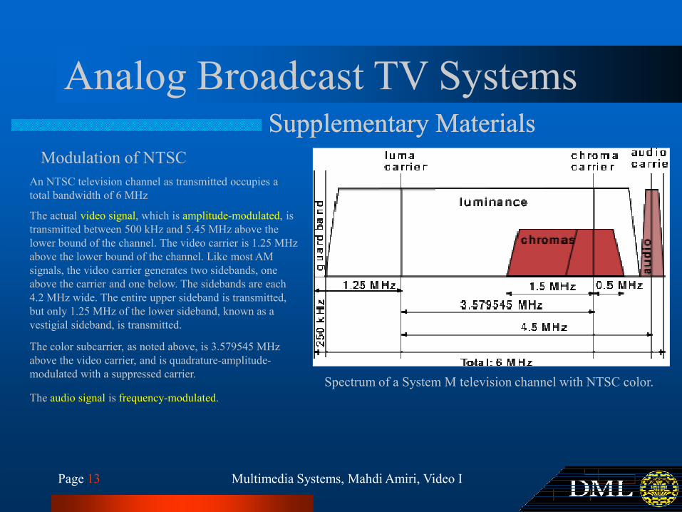
An NTSC television channel as transmitted occupies a
total bandwidth of 6 MHz
Modulation of NTSC
The actual video signal, which is amplitude-modulated, is
transmitted between 500 kHz and 5.45 MHz above the
lower bound of the channel. The video carrier is 1.25 MHz
above the lower bound of the channel. Like most AM
Multimedia Systems, Mahdi Amiri, Video IPage 13
Spectrum of a System M television channel with NTSC color.
above the lower bound of the channel. Like most AM
signals, the video carrier generates two sidebands, one
above the carrier and one below. The sidebands are each
4.2 MHz wide. The entire upper sideband is transmitted,
but only 1.25 MHz of the lower sideband, known as a
vestigial sideband, is transmitted.
The color subcarrier, as noted above, is 3.579545 MHz
above the video carrier, and is quadrature-amplitude-
modulated with a suppressed carrier.
The audio signal is frequency-modulated.
Analog Broadcast TV SystemsSupplementary MaterialsSupplementary Materials
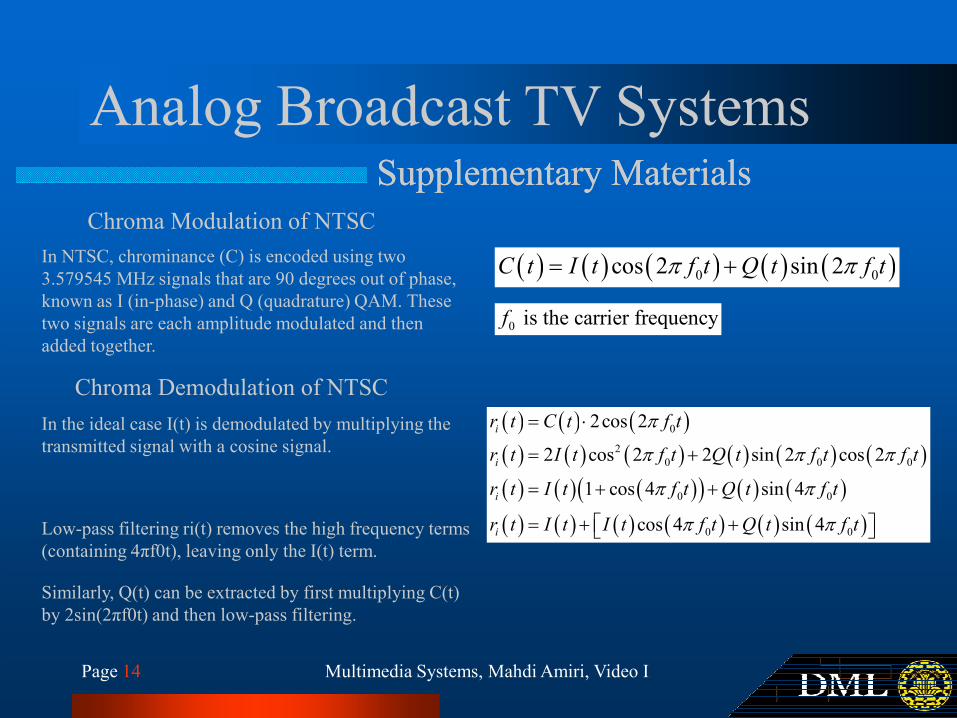
Chroma Modulation of NTSC
In NTSC, chrominance (C) is encoded using two
3.579545 MHz signals that are 90 degrees out of phase,
known as I (in-phase) and Q (quadrature) QAM. These
two signals are each amplitude modulated and then
added together.
( ) ( ) ( ) ( ) ( )0 0cos 2 sin 2C t I t f t Q t f tπ π= +
0 is the carrier frequencyf
Multimedia Systems, Mahdi Amiri, Video IPage 14
In the ideal case I(t) is demodulated by multiplying the
transmitted signal with a cosine signal.
Chroma Demodulation of NTSC
( ) ( ) ( )( ) ( ) ( ) ( ) ( ) ( )( ) ( ) ( )( ) ( ) ( )( ) ( ) ( ) ( ) ( ) ( )
0
2
0 0 0
0 0
0 0
2cos 2
2 cos 2 2 sin 2 cos 2
1 cos 4 sin 4
cos 4 sin 4
i
i
i
i
r t C t f t
r t I t f t Q t f t f t
r t I t f t Q t f t
r t I t I t f t Q t f t
π
π π π
π π
π π
= ⋅
= +
= + +
= + + Low-pass filtering ri(t) removes the high frequency terms
(containing 4πf0t), leaving only the I(t) term.
Similarly, Q(t) can be extracted by first multiplying C(t)
by 2sin(2πf0t) and then low-pass filtering.
Analog Broadcast TV SystemsSupplementary MaterialsSupplementary Materials
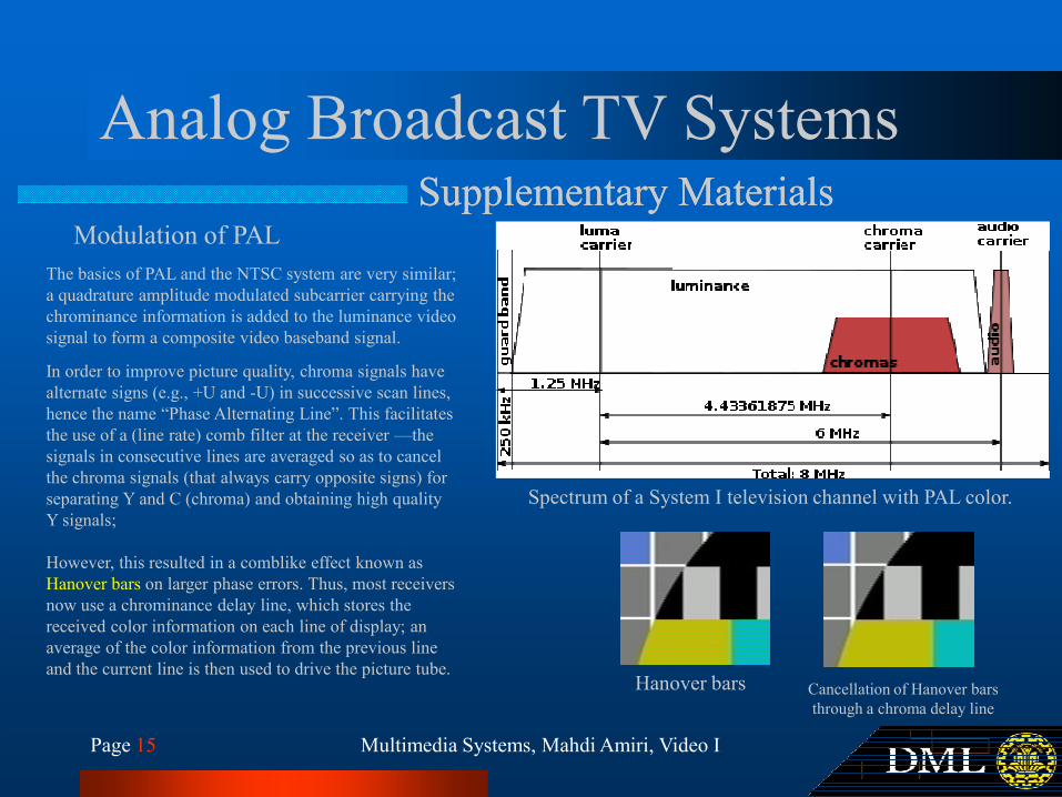
The basics of PAL and the NTSC system are very similar;
a quadrature amplitude modulated subcarrier carrying the
chrominance information is added to the luminance video
signal to form a composite video baseband signal.
Modulation of PAL
In order to improve picture quality, chroma signals have
alternate signs (e.g., +U and -U) in successive scan lines,
Multimedia Systems, Mahdi Amiri, Video IPage 15
Spectrum of a System I television channel with PAL color.
alternate signs (e.g., +U and -U) in successive scan lines,
hence the name “Phase Alternating Line”. This facilitates
the use of a (line rate) comb filter at the receiver —the
signals in consecutive lines are averaged so as to cancel
the chroma signals (that always carry opposite signs) for
separating Y and C (chroma) and obtaining high quality
Y signals;
However, this resulted in a comblike effect known as
Hanover bars on larger phase errors. Thus, most receivers
now use a chrominance delay line, which stores the
received color information on each line of display; an
average of the color information from the previous line
and the current line is then used to drive the picture tube.Hanover bars Cancellation of Hanover bars
through a chroma delay line
Analog Broadcast TV SystemsSupplementary MaterialsSupplementary Materials
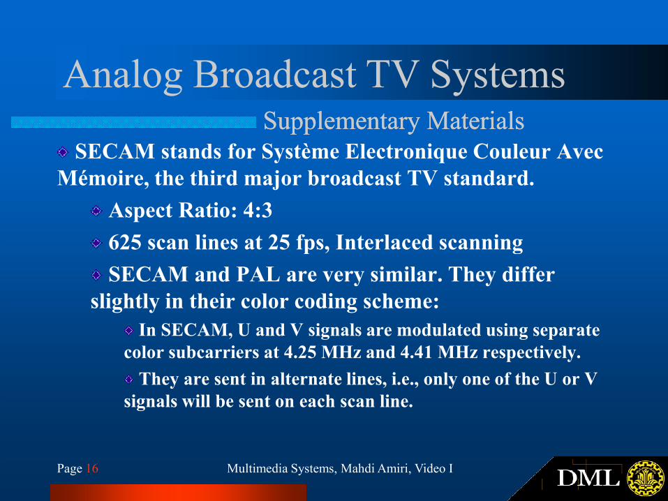
SECAM stands for Système Electronique Couleur Avec
Mémoire, the third major broadcast TV standard.
Aspect Ratio: 4:3
625 scan lines at 25 fps, Interlaced scanning
Multimedia Systems, Mahdi Amiri, Video IPage 16
625 scan lines at 25 fps, Interlaced scanning
SECAM and PAL are very similar. They differ
slightly in their color coding scheme:
In SECAM, U and V signals are modulated using separate
color subcarriers at 4.25 MHz and 4.41 MHz respectively.
They are sent in alternate lines, i.e., only one of the U or V
signals will be sent on each scan line.
Analog Broadcast TV SystemsSupplementary MaterialsSupplementary Materials
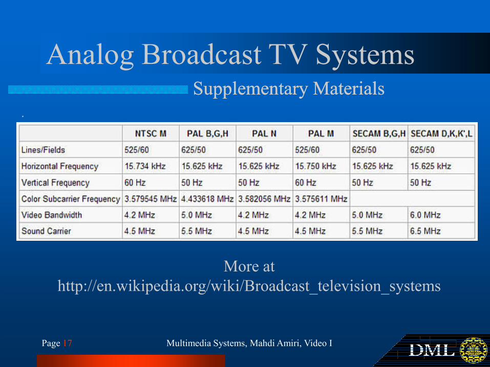
.
Multimedia Systems, Mahdi Amiri, Video IPage 17
More at
http://en.wikipedia.org/wiki/Broadcast_television_systems
Analog Color VideoSignal ProtocolsSignal Protocols
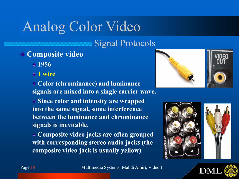
Composite video
1956
1 wire
Color (chrominance) and luminance
signals are mixed into a single carrier wave.
Multimedia Systems, Mahdi Amiri, Video IPage 18
signals are mixed into a single carrier wave.
Since color and intensity are wrapped
into the same signal, some interference
between the luminance and chrominance
signals is inevitable.
Composite video jacks are often grouped
with corresponding stereo audio jacks (the
composite video jack is usually yellow)
Analog Color VideoSignal ProtocolsSignal Protocols
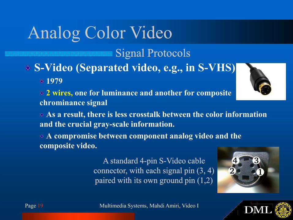
S-Video (Separated video, e.g., in S-VHS)1979
2 wires, one for luminance and another for composite
chrominance signal
As a result, there is less crosstalk between the color information
Multimedia Systems, Mahdi Amiri, Video IPage 19
As a result, there is less crosstalk between the color information
and the crucial gray-scale information.
A compromise between component analog video and the
composite video.
A standard 4A standard 4--pin Spin S--Video cable Video cable
connector, with each signal pin (3, 4) connector, with each signal pin (3, 4)
paired with its own ground pin (1,2)paired with its own ground pin (1,2)
Analog Color VideoSignal ProtocolsSignal Protocols
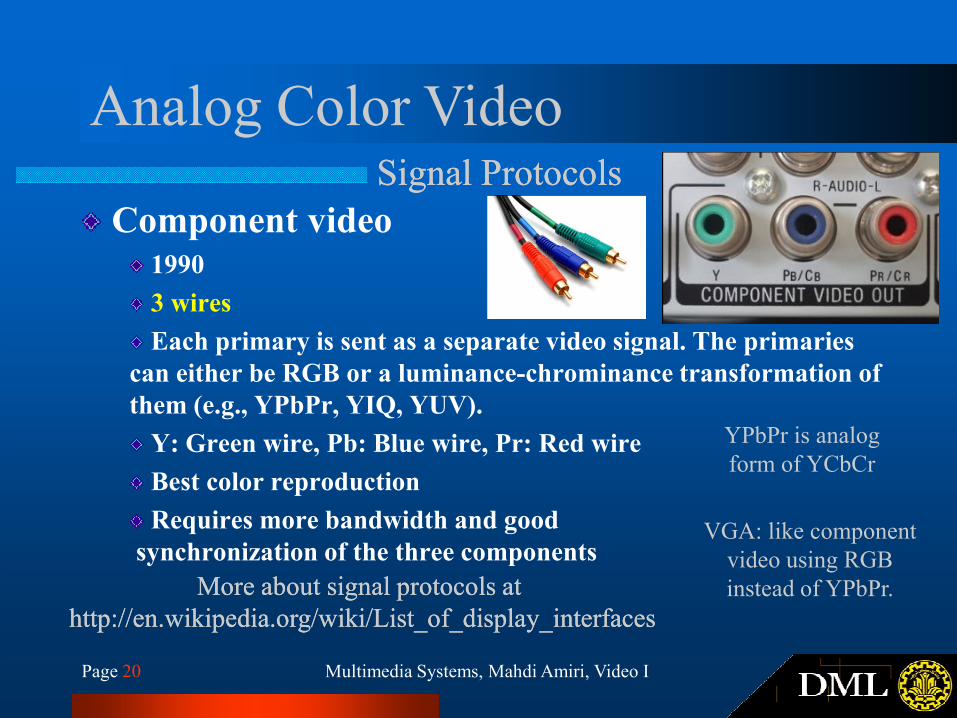
Component video1990
3 wires
Each primary is sent as a separate video signal. The primaries
can either be RGB or a luminance-chrominance transformation of
Multimedia Systems, Mahdi Amiri, Video IPage 20
can either be RGB or a luminance-chrominance transformation of
them (e.g., YPbPr, YIQ, YUV).
Y: Green wire, Pb: Blue wire, Pr: Red wire
Best color reproduction
Requires more bandwidth and good
synchronization of the three components
More about signal protocols atMore about signal protocols at
http://en.wikipedia.org/wiki/List_of_display_interfaceshttp://en.wikipedia.org/wiki/List_of_display_interfaces
YPbPr is analog
form of YCbCr
VGA: like component
video using RGB
instead of YPbPr.
Digital VideoAdvantagesAdvantages
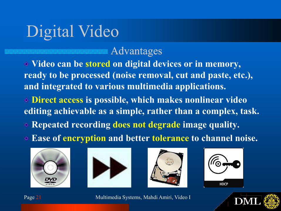
Video can be stored on digital devices or in memory,
ready to be processed (noise removal, cut and paste, etc.),
and integrated to various multimedia applications.
Direct access is possible, which makes nonlinear video
editing achievable as a simple, rather than a complex, task.
Multimedia Systems, Mahdi Amiri, Video IPage 21
editing achievable as a simple, rather than a complex, task.
Repeated recording does not degrade image quality.
Ease of encryption and better tolerance to channel noise.
Digital VideoHDTV vs. Conventional TVHDTV vs. Conventional TV
HDTV has higher resolution
1280 × 720 or 1920 × 1080.
HDTV has a much wider aspect ratio of 16:9 instead of
4:3.
Multimedia Systems, Mahdi Amiri, Video IPage 22
4:3.
16:9 is closer to aspect ratio of the human eye sight
HDTV moves toward progressive (non-interlaced) scan.
The rationale is that interlacing introduces serrated
edges to moving objects and flickers along horizontal
edges.
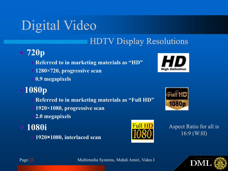
Digital VideoHDTV Display ResolutionsHDTV Display Resolutions
720pReferred to in marketing materials as “HD”
1280×720, progressive scan
0.9 megapixels
1080p
Multimedia Systems, Mahdi Amiri, Video IPage 23
1080pReferred to in marketing materials as “Full HD”
1920×1080, progressive scan
2.0 megapixels
1080i1920×1080, interlaced scan
Aspect Ratio for all is Aspect Ratio for all is
16:9 (W:H)16:9 (W:H)
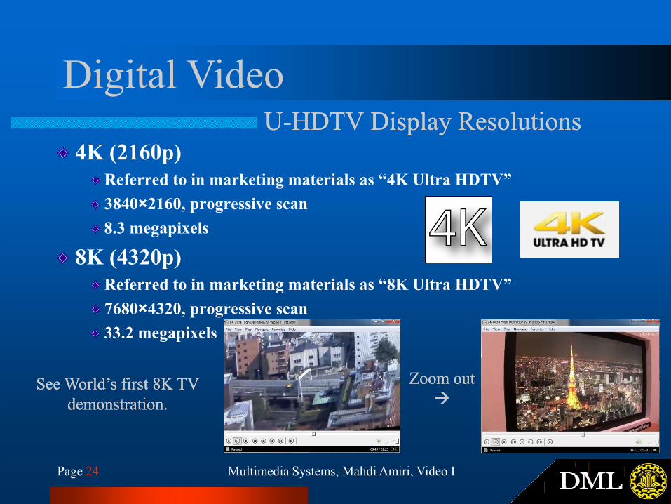
Digital VideoUU--HDTV Display ResolutionsHDTV Display Resolutions
4K (2160p)
Referred to in marketing materials as “4K Ultra HDTV”
3840×2160, progressive scan
8.3 megapixels
8K (4320p)
Multimedia Systems, Mahdi Amiri, Video IPage 24
8K (4320p)
Referred to in marketing materials as “8K Ultra HDTV”
7680×4320, progressive scan
33.2 megapixels
See World’s first 8K TV See World’s first 8K TV
demonstration.demonstration.
Zoom outZoom out
��
Digital Color VideoSignal ProtocolsSignal Protocols
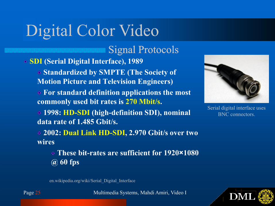
SDI (Serial Digital Interface), 1989
Standardized by SMPTE (The Society of
Motion Picture and Television Engineers)
For standard definition applications the most
commonly used bit rates is 270 Mbit/s.
Multimedia Systems, Mahdi Amiri, Video IPage 25
commonly used bit rates is 270 Mbit/s.
1998: HD-SDI (high-definition SDI), nominal
data rate of 1.485 Gbit/s.
2002: Dual Link HD-SDI, 2.970 Gbit/s over two
wires
These bit-rates are sufficient for 1920×1080
@ 60 fps
en.wikipedia.org/wiki/Serial_Digital_Interface
Serial digital interface uses
BNC connectors.
Digital Color VideoSignal ProtocolsSignal Protocols
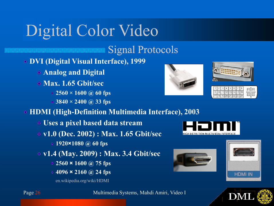
DVI (Digital Visual Interface), 1999
Analog and Digital
Max. 1.65 Gbit/sec
2560 × 1600 @ 60 fps
3840 × 2400 @ 33 fps
Multimedia Systems, Mahdi Amiri, Video IPage 26
3840 × 2400 @ 33 fps
HDMI (High-Definition Multimedia Interface), 2003
Uses a pixel based data stream
v1.0 (Dec. 2002) : Max. 1.65 Gbit/sec
1920×1080 @ 60 fps
v1.4 (May. 2009) : Max. 3.4 Gbit/sec
2560 × 1600 @ 75 fps
4096 × 2160 @ 24 fps
en.wikipedia.org/wiki/HDMI
Digital Color VideoSignal ProtocolsSignal Protocols
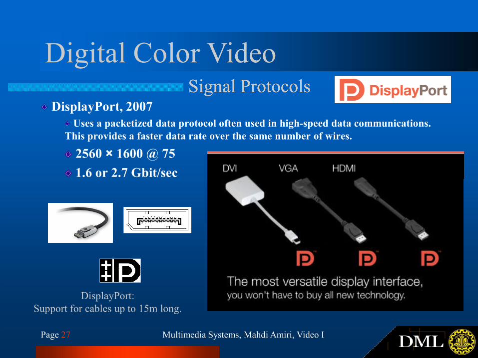
DisplayPort, 2007
Uses a packetized data protocol often used in high-speed data communications.
This provides a faster data rate over the same number of wires.
2560 × 1600 @ 75
1.6 or 2.7 Gbit/sec
Multimedia Systems, Mahdi Amiri, Video IPage 27
1.6 or 2.7 Gbit/sec
DisplayPort:
Support for cables up to 15m long.
Digital Color VideoSignal Protocols, AdaptersSignal Protocols, Adapters
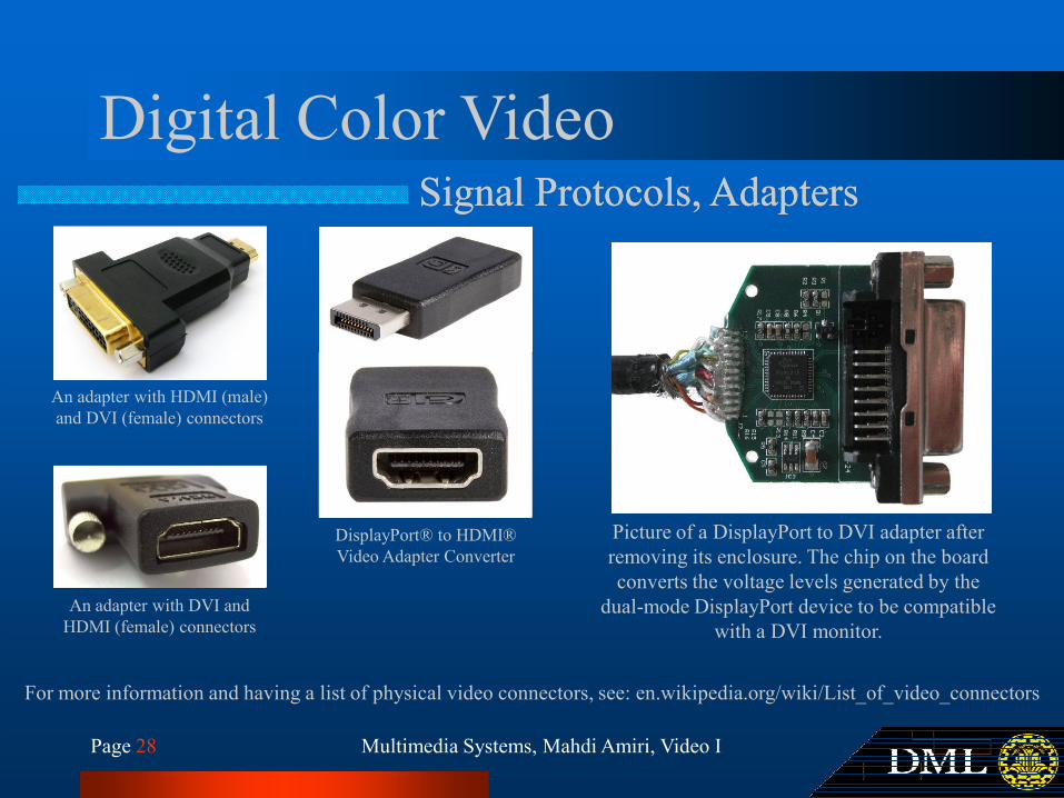
An adapter with HDMI (male)
Multimedia Systems, Mahdi Amiri, Video IPage 28
Picture of a DisplayPort to DVI adapter after
removing its enclosure. The chip on the board
converts the voltage levels generated by the
dual-mode DisplayPort device to be compatible
with a DVI monitor.
An adapter with HDMI (male)
and DVI (female) connectors
An adapter with DVI and
HDMI (female) connectors
For more information and having a list of physical video connectors, see: en.wikipedia.org/wiki/List_of_video_connectors
DisplayPort® to HDMI®
Video Adapter Converter
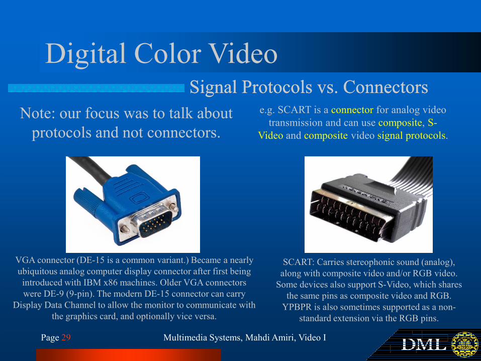
Digital Color VideoSignal Protocols vs. ConnectorsSignal Protocols vs. Connectors
Note: our focus was to talk about
protocols and not connectors.
e.g. SCART is a connector for analog video
transmission and can use composite, S-
Video and composite video signal protocols.
Multimedia Systems, Mahdi Amiri, Video IPage 29
VGA connector (DE-15 is a common variant.) Became a nearly
ubiquitous analog computer display connector after first being
introduced with IBM x86 machines. Older VGA connectors
were DE-9 (9-pin). The modern DE-15 connector can carry
Display Data Channel to allow the monitor to communicate with
the graphics card, and optionally vice versa.
SCART: Carries stereophonic sound (analog),
along with composite video and/or RGB video.
Some devices also support S-Video, which shares
the same pins as composite video and RGB.
YPBPR is also sometimes supported as a non-
standard extension via the RGB pins.
Thank You
Multimedia SystemsMultimedia Systems
Video I (Basics of Analog and Digital Video)Video I (Basics of Analog and Digital Video)
Multimedia Systems, Mahdi Amiri, Video IPage 30
Thank You
1. http://ce.sharif.edu/~m_amiri/
2. http://www.dml.ir/
FIND OUT MORE AT...
Next Session: Critical Reading ReviewNext Session: Critical Reading Review