lec5 motor control - lanka education and research …rohan/teaching/en2532/lectures/lec5...motor...
TRANSCRIPT
Motor ControlMotor Control
Prof. Rohan MunasingheDepartment of Electronic and Telecommunication EngineeringFaculty of Engineering
University of Moratuwa 10400
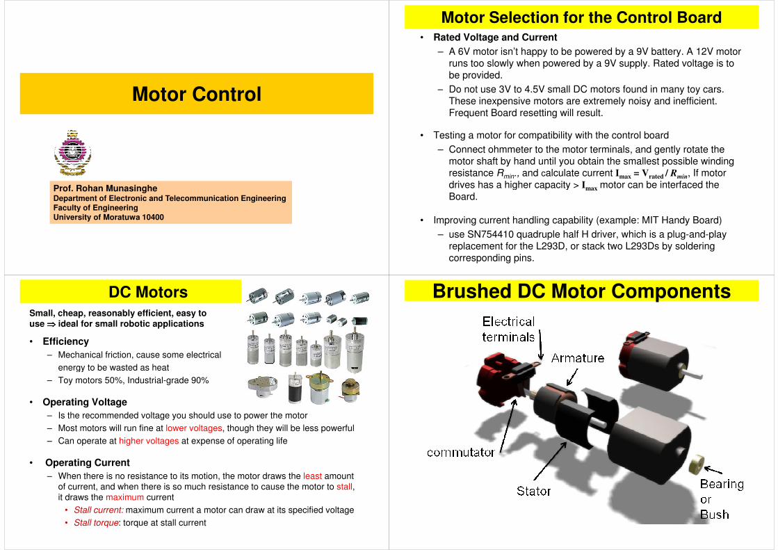
Motor Selection for the Control Board• Rated Voltage and Current
– A 6V motor isn’t happy to be powered by a 9V battery. A 12V motor runs too slowly when powered by a 9V supply. Rated voltage is to
be provided.
– Do not use 3V to 4.5V small DC motors found in many toy cars. – Do not use 3V to 4.5V small DC motors found in many toy cars. These inexpensive motors are extremely noisy and inefficient.
Frequent Board resetting will result.
• Testing a motor for compatibility with the control board
– Connect ohmmeter to the motor terminals, and gently rotate the motor shaft by hand until you obtain the smallest possible winding resistance Rmin., and calculate current I
max= V
rated/ Rmin, If motor
drives has a higher capacity > I motor can be interfaced the drives has a higher capacity > Imax
motor can be interfaced the
Board.
• Improving current handling capability (example: MIT Handy Board)
– use SN754410 quadruple half H driver, which is a plug-and-play replacement for the L293D, or stack two L293Ds by soldering
corresponding pins.
• Efficiency
– Mechanical friction, cause some electrical
energy to be wasted as heat
Small, cheap, reasonably efficient, easy to use ⇒⇒⇒⇒ ideal for small robotic applications
DC Motors
energy to be wasted as heat
– Toy motors 50%, Industrial-grade 90%
• Operating Voltage
– Is the recommended voltage you should use to power the motor
– Most motors will run fine at lower voltages, though they will be less powerful
– Can operate at higher voltages at expense of operating life
• Operating Current
– When there is no resistance to its motion, the motor draws the least amount
of current, and when there is so much resistance to cause the motor to stall,
it draws the maximum current
• Stall current: maximum current a motor can draw at its specified voltage
• Stall torque: torque at stall current
Brushed DC Motor Components
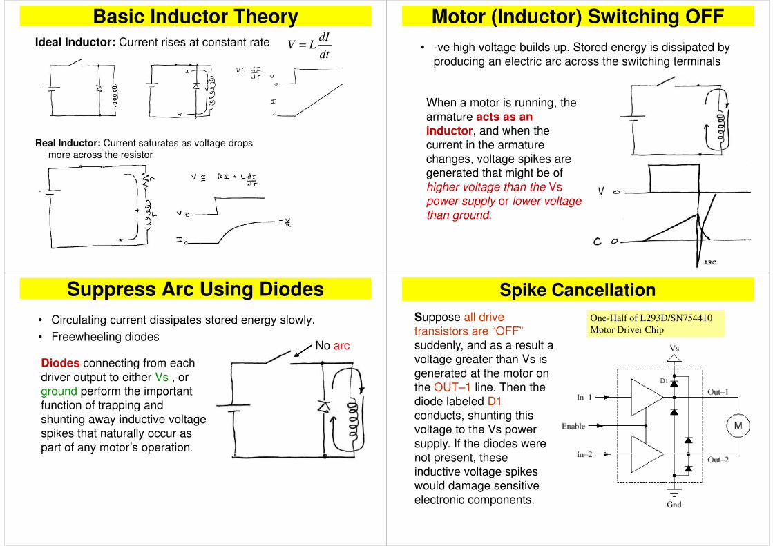
Basic Inductor Theory
dt
dILV =Ideal Inductor: Current rises at constant rate
Real Inductor: Current saturates as voltage drops
more across the resistor
Motor (Inductor) Switching OFF
• -ve high voltage builds up. Stored energy is dissipated by
producing an electric arc across the switching terminals
When a motor is running, the
armature acts as an inductor, and when the
current in the armature
changes, voltage spikes are
generated that might be of
higher voltage than the Vs higher voltage than the Vs
power supply or lower voltage
than ground.
Suppress Arc Using Diodes
• Circulating current dissipates stored energy slowly.
• Freewheeling diodesNo arc
Diodes connecting from each Diodes connecting from each
driver output to either Vs , or
ground perform the important
function of trapping and
shunting away inductive voltage
spikes that naturally occur as
part of any motor’s operation.part of any motor’s operation
Suppose all drive
transistors are “OFF”
suddenly, and as a result a
voltage greater than Vs is
One-Half of L293D/SN754410
Motor Driver Chip
Spike Cancellation
voltage greater than Vs is
generated at the motor on
the OUT–1 line. Then the
diode labeled D1
conducts, shunting this
voltage to the Vs power
supply. If the diodes were
not present, these not present, these
inductive voltage spikes
would damage sensitive
electronic components.

MOSFET Drivers
MOSFETs
• Smaller Bias Current compared to BJT
• Almost zero bias current under steady state condition (ON
or OFF)or OFF)
• Low ON Resistance
• Higher current
• Fast Switching speed (can be uses to control motor speed
via PWM)
H-Bridge Circuit
• Rotation of the DC motor can be controlled (CW or CCW)
• Mostly used 2 different channel MOS-FETs • 2 N-Channel MOS-FETs• 2 P-Channel MOS-FETs
CW Rotattion
CW
• Two MOS-FETs are ON and the others are OFF
• One MOS-FET Drive the positive supply, and the other one is driving the negative supply
CCW Rotattion
CCW
• MOS-FETs are working in the apposite condition fron the CCW rotation
• The polarity of the motor become the apposite from the CCW thus makes the DC motor turning in the apposite direction (CW)
• Two MOS-FETs are ON and the others two are OFF
• One MOS-FET Drive the positive supply, and the other one is driving the negative supply

MOSFET Driven through Optocouplers
• Optocouplers are used to separate the controller and motor ground signal
• The N-Channels are biased to +VSS
• The P-Channels are biased to -VSS
• Optocopuplers are supplied from the controller with different ground signal from the motor supply
Bias for CW Rotation
CW
1
10
0
Q4=on
Q2=on
Bias for CCW Rotation
CCW
0 1
0Q3=on
Q1=on
1
Speed Control for CW
SpeedCW
1
10
PWM
Q4=on
Q2 Pulsed
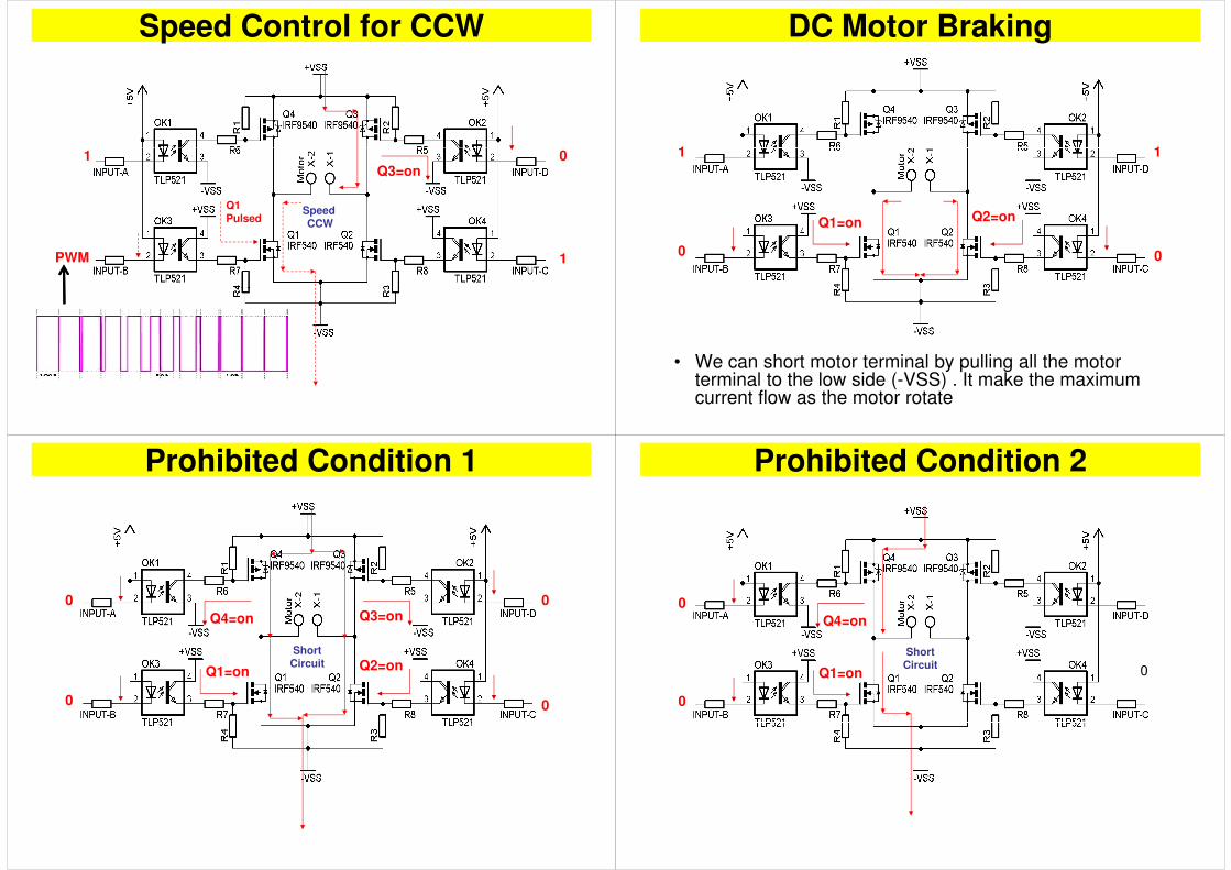
Speed Control for CCW
01
Speed CCW
PWM 1
0Q3=on
Q1Pulsed
1
DC Motor Braking
11 1
0
Q2=on
0
Q1=on
1
• We can short motor terminal by pulling all the motor terminal to the low side (-VSS) . It make the maximum current flow as the motor rotate
Prohibited Condition 1
ShortCircuit
0
Q2=on
0
Q1=on
0Q3=on
0
Q4=on
Prohibited Condition 2
0
ShortCircuit
0
Q1=on
0
Q4=on

Prohibited Condition 3
ShortCircuit
0
Q2=on
0Q3=on
0
Decoder
• Logic Decoder can be used to Protect H-Bridge from the Prohibited Conditions
Input A Input B Input C Input D Conditions
0 0 0 0 All Circuits short (Prohibited condition)
0 0 0 1 Short Circuit (Prohibited condition)
0 0 1 0 Short Circuit (Prohibited condition)
0 0 1 1 Short Circuit (Prohibited condition)
0 1 0 0 Short Circuit (Prohibited condition)
0 1 0 1 Motor Turn Clockwise
0 1 1 0 Brake (Upper Part is closed loop)
0 1 1 1 Circuit Open (Motor Off / Free running)
1 0 0 0 Short Circuit (Prohibited condition)
1 0 0 1 Brake (Lower Part is closed loop)1 0 0 1 Brake (Lower Part is closed loop)
1 0 1 0 Motor Turn Counter Clockwise
1 0 1 1 Circuit Open (Motor Off / Free running)
1 1 0 0 Short Circuit (Prohibited condition)
1 1 0 1 Circuit Open (Motor Off / Free running)
1 1 1 0 Circuit Open (Motor Off / Free running)
1 1 1 1 All Circuits Open (Motor Off / Free running)
Assignment 2
• Design the following combinational logic circuit, which will make sure that prohibited conditions won’t be generated.
Combinational
A
B Prohibited Determine ...Combinational
Logic Circuit
B
C
D
Prohibited Conditions won’t happen
required inputs
...
L298 Dual Full Bridge Driver (4A)
Motor
Control
PinsUp to 46V, 4A
Motor Terminals < 2A
5 - 7 V
Motor Control Pins

• To Drive inductive loads : solenoids, relays, DC / stepper
motors
L298 Dual Full Bridge Driver (4A)
External smoothing caps
Homework: Draw Truth Table for Out1 and Out2 as a functions of In1 and In2
• Power
– Product of the output shaft’s rotational velocity and torque
– Output power is zero when
Torque is zero: Motor is spinning freely with no load on the shaft. Rotational
velocity is at its highest, but the torque is zero, and it’s not driving any
Power and Speed of DC Motors
velocity is at its highest, but the torque is zero, and it’s not driving any
mechanism (Actually, the motor is doing some work to overcome internal
friction, but that is of no value as output power)
Rotational velocity is zero: Motor is stalled, it is producing its maximal
torque. But as there is no motion, no work is delivered onto the load
– In between two extremes, output power shows a parabolic relationship
Feedback Control• Example: Air conditioner
• Temperature sensing system (sensor or mechanism) feeds back room temperature, and compares it with the desired temperature.
Error is determined.
• Use the error signal (positive or negative) to adjust the cool airflow • Use the error signal (positive or negative) to adjust the cool airflow to the room.
• If error is +ve reduce cool air flow
• If error is –ve increase cool air flow
• There is a delay in air temperature measuring system. Delayed response can cause oscillations in room temperature.
27
Proportional Control of Motorscontrol signal is proportional to the amount of error: Generates a stronger
control signal when the present state is farther away from the goal state
At t=0, suppose that the setpoint =100 and actual position=0. Then
e(0)=100, so the motor turns at 100% power, driving the wheel toward the
desired position. As it moves, the error becomes progressively smaller.
When it is at position=50, the error is only 50, and the motor is given only
50% power. When it arrives at the intended position of 100, the error is zero,
and the motor turns off momentarily.
28
Proportional Gain (ratio between error and power): Instead of a one-to-
one ratio between error and motor %power, modify the controller so it
multiplies the error value by 5. The wheel should reach the set-point faster,
and it should resist being turned away from it much more aggressively.

Overshoot:
Response moves beyond set-point, and stops and turns back.
Oscillations:
Proportional Control of Motors
Oscillations:
After an overshoot, error becomes –ve, thus, proportional controller drives
the motor in the opposite direction. In the subsequent motion, motor might
“undershoot” as well. This overshoot and undershoot phenomena repeats
for a while, and gradually, the oscillation is expected to die out.
29
Controller Design:
Design to minimize both overshoot and oscillation, but let little overshoot to
improve system response to reach the set-point as quickly as possible.
Kp =10
Kp =10: Full-power is delivered to
motor as long as error>10. When
position falls below 10, power
command begin to fall off. Position
overshoots, and shows little oscillation
Steady State Error (Offset):
Proportional Gain Kp
Kp =20
Steady State Error (Offset):
System does not stabilize at the
set-point, but at 1. This generates
a power command of 10%, which
is too small to activate the motor
Kp =20: should ameliorate the
offset problem, since the same
30
offset problem, since the same
static error will result in a higher power command
Offset has been eliminated, but at
cost of oscillations before settling
Kp =30
Causes predominant oscillation
Kp =50
Proportional Gain Kp
Kp =30
Kp =50
Oscillation behavior has taken over.
System is too sensitive (responsive). A
slight error causes huge power delivered
through the motor. Subsequent slight
errors in +ve and –ve directions causes
Kp =50
31
sustainable swing around the set point .
While the position error is small on the
graph, the power swings vigorously.
• Proportional controller drives the wheel to the set point faster, but
results in overshoots and oscillations at higher gains
• Observation: At larger errors, velocity is small, and at smaller errors
Proportional-Derivative Control
velocity is large (as motor swings around the set point)
Use derivative control
• What if we reduce motor power by a quantity proportional to speed.
• No effect at larger errors
32
• No effect at larger errors
• Reduce power near set point (reduce oscillations)
This looks like what we need to improve response while reducing
overshoot

Kp=4, KD=1:
Overshoot is minimized, and there is
no any significant oscillatory behavior.
Kp=4, KD=1
Proportional-Derivative Control
Kp=10, KD=5:
KD is too large. Controller puts on the
brakes too aggressively and the
system stops too early before reaching
Kp=10, KD=5
33
the set-point. When the velocity hits
zero, the proportional gain kicks in
again and the system corrects
Servo Motors
Servo Motors
• The servo motor is actually an assembly of four parts:
– DC motor
– Gear reduction unit
– Position sensor– Position sensor
– Feedback control circuit
• Three wires of a servo: power, ground, control.
– The power source must be constantly applied
• Servo shaft typically does not rotate 3600 like a DC motor, but can only rotate ±1000 from the centre position.
• servo has its own power electronics, so very little power flows over the
Servo Motors cntd..
• servo has its own power electronics, so very little power flows over the control signal.
• Servo motors require a 5~6 V DC power supply. This can be taken from the control board power if the servo's aren't doing too much work. Otherwise, a separate power supply is recommended
• If available DC Voltage is higher, 1N4001 diodes can be used to drop the voltage down to around 6V.
• Servo will hold the position and resists disturbances to deflect from the • Servo will hold the position and resists disturbances to deflect from the command position.
• Servo needs a consistent (repetitive) voltage pulse to hold the position.
• Turn rate : is the time it takes to move between the two extreme positions. It is about few seconds in high torque motors

Servo Motor Control cntd..• Servo PWM method is different from the speed control PWM
– Speed control PWM: overall duty cycle (% on-time) determines the
power/speed of the motor
– Servo PWM: length of the pulse is used as the shaft position command
• Futaba S148 : 920ms (full counterclockwise), 1520ms (center), 2120ms (full • Futaba S148 : 920ms (full counterclockwise), 1520ms (center), 2120ms (full clockwise)
– The servo control pulse modulated frequency is 50Hz (20 ms period), which
means that you can command the servo in every 20ms “go here”
20ms
Servo Motor Specifications
★★★
★★
★
★★
Servo Motors on MIT Handy Board
control
control
servo 16V
servo 25V
9.6V
Winch Servo
• Winch servo rotates continuously
– Can be used for robot’s main drive motors
• Conversion
– Potentiometer is replaced by a pair of fixed resistors, and the position – Potentiometer is replaced by a pair of fixed resistors, and the position feedback is taken from the center (feedback signal becomes a
constant, and is referred to center position)
– Therefore, motor continues to turn due to error (reference - center).
– This methods allows both speed and direction control. the farther the
control signal is away from the center position, the faster the motor turns
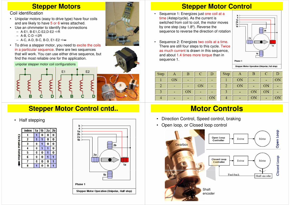
Stepper MotorsCoil identification
• Unipolar motors (easy to drive type) have four coils and are likely to have 5 or 6 wires attached.
• Use an ohmmeter to identify the connections– A-E1, B-E1,C-E2,D-E2 �R
– A-B, C-D �2R– A-B, C-D �2R
– A-C, A-D, B-C, B-D, E1-E2 �∞∞∞∞
• To drive a stepper motor, you need to excite the coils in a particular sequence. there are two sequences
that will work. You can use either drive sequence, but find the most reliable one for the application.
unipolar stepper motor coil configurations
E1 E2
• Sequence 1: Energizes just one coil at a time (4step/cycle). As the current is switched from coil to coil, the motor moves
by one step (say 1.80). Reverse the sequence to reverse the direction of rotation
Stepper Motor Control
• Sequence 2: Energizes two coils at a time. There are still four steps to this cycle. Twice as much current is drawn in this sequence,
and about 1.4 times more torque than in sequence 1.
Stepper Motor Control cntd..
• Half stepping
Motor Controls
• Direction Control, Speed control, braking
• Open loop, or Closed loop control
Gearbox
Shaft
encoder
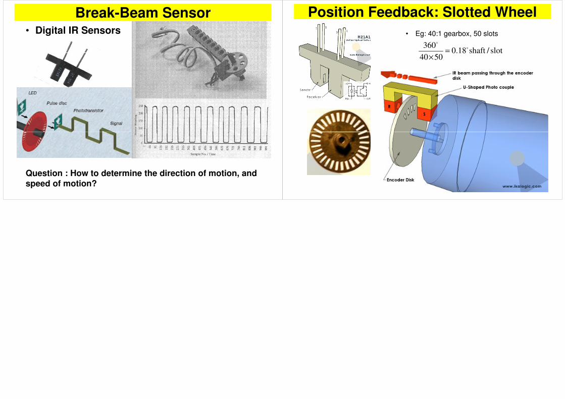
Break-Beam Sensor• Digital IR Sensors
Question : How to determine the direction of motion, and
speed of motion?
Position Feedback: Slotted Wheel
• Eg: 40:1 gearbox, 50 slots
slot/shaft18.05040
360 o
o
=
×