lect e 9lecture 9 usci module - home | cmu robotics club • set the ucaxrxifg if ucbrkie bit is...
TRANSCRIPT

MSP430 Teaching MaterialsUBI
Lect e 9Lecture 9USCI Module
T I t t I t dTexas Instruments IncorporatedUniversity of Beira Interior (PT)
Pedro Dinis Gaspar, António Espírito Santo, Bruno Ribeiro, Humberto SantosUniversity of Beira Interior, Electromechanical Engineering Department
30 bi
>> Contents
www.msp430.ubi.pt
Copyright 2009 Texas Instruments All Rights Reserved
www.msp430.ubi.pt

ContentsUBI
USCI module introduction
USCI operation: UART mode
USCI ti SPI d USCI operation: SPI mode
USCI operation: I2C mode
USCI registers: UART, SPI and I2C modes
>> Contents2
Copyright 2009 Texas Instruments All Rights Reserved
www.msp430.ubi.pt

USCI module introduction (1/3)UBI
Although supporting UART, SPI and I2C, the USCI (Universal Serial Communication Interface) module is a (Universal Serial Communication Interface) module is a communications interface specially designed to interconnect with high-speed industrial protocols: LIN (Local interconnect Network), used for low-cost modules
in cars e.g. door modules, alarms, rain-sensors; IrDA (Infrared Data Association).IrDA (Infrared Data Association).
The USCI module is available in the following devices:• MSP430F5xx;
MSP430F4xx and MSP430FG41xx;• MSP430F4xx and MSP430FG41xx;• MSP430F2xx.
>> Contents3
Copyright 2009 Texas Instruments All Rights Reserved
www.msp430.ubi.pt

USCI module introduction (2/3)UBI
The USCI module supports: Low power operating modes (with auto-start); Low power operating modes (with auto-start);
Two individual blocks:• USCI A: UART and SPI;• USCI_A: UART and SPI;• USCI_B: SPI and I2C.
Double buffered TX/RX;Double buffered TX/RX;
Baud rate/bit clock generator:• With auto-baud rate detect;With auto baud rate detect;• Flexible clock source.
RX glitch suppression;RX glitch suppression;
DMA enabled;
E d t ti
>> Contents4
Copyright 2009 Texas Instruments All Rights Reserved
www.msp430.ubi.pt
Error detection.

USCI module introduction (3/3)UBI
USCI block diagram:
>> Contents5
Copyright 2009 Texas Instruments All Rights Reserved
www.msp430.ubi.pt

USCI operation: UART mode (1/17)UBI
In asynchronous mode, the USCI_Ax modules connect the MSP430 to an external system via two external pins the MSP430 to an external system via two external pins, UCAxRXD and UCAxTXD;
UART mode is selected when the UCSYNC bit is cleared;
USCI transmits and receives characters asynchronously; USCI transmits and receives characters asynchronously;
Timing for each character is based on the selected baud Timing for each character is based on the selected baud rate of the USCI;
i d i h l k f Transmit and receive use the same clock frequency leading to the same baud rate;
>> Contents6
Copyright 2009 Texas Instruments All Rights Reserved
www.msp430.ubi.pt

USCI operation: UART mode (2/17)UBI
USCI operation in UART mode block diagram:
>> Contents7
Copyright 2009 Texas Instruments All Rights Reserved
www.msp430.ubi.pt

USCI operation: UART mode (3/17)UBI
Recommended initialization/re-configuration process:
Set UCSWRST (BIS.B #UCSWRST,&UCAxCTL1);
Initialize all USCI registers with UCSWRST = 1 (including UCAxCTL1);
Configure ports;
Clear UCSWRST via software:(BIC.B #UCSWRST,&UCAxCTL1);
Enable interrupts (optional) via UCAxRXIE and/or UCAxTXIE.
>> Contents8
Copyright 2009 Texas Instruments All Rights Reserved
www.msp430.ubi.pt

USCI operation: UART mode (4/17)UBI
Character format specified as follows: Start bit; Start bit; Seven or eight data bits; Even/odd/no parity bit; Address bit (address-bit mode); One or two stop bits.
The UCMSB bit controls the direction of the transfer and selects LSB (usual in UART communication) or MSB first
>> Contents9
Copyright 2009 Texas Instruments All Rights Reserved
www.msp430.ubi.pt
selects LSB (usual in UART communication) or MSB first.

USCI operation: UART mode (5/17)UBI
Asynchronous communication formats:
Idle-line multiprocessor communication protocol(minimum of two devices):( )• IDLE is detected after > 10 periods of continuous marks
after the stop bit;The fi st cha acte afte IDLE is an add ess
• The first character after IDLE is an address;• Can be programmed to receive only address characters.
>> Contents10
Copyright 2009 Texas Instruments All Rights Reserved
www.msp430.ubi.pt

USCI operation: UART mode (6/17)UBI
Asynchronous communication formats (continued):
Address-bit multiprocessor communication protocol (minimum of three devices):( )• An extra bit in the received character marks an address
character;UART can be p og ammed to ecei e onl add ess • UART can be programmed to receive only address characters.
>> Contents11
Copyright 2009 Texas Instruments All Rights Reserved
www.msp430.ubi.pt

USCI operation: UART mode (7/17)UBI
Automatic baud rate detection (UCMODEx = 11):
Data frame is preceded by a synchronization sequence:• Break: Detected when 11 or more continuous zeros
( ) i d(spaces) are received;• Synch field: Data 055h inside a byte field.
>> Contents12
Copyright 2009 Texas Instruments All Rights Reserved
www.msp430.ubi.pt
USCI operation: UART mode (8/17)UBI
Automatic baud rate detection (UCMODEx = 11):
The baud rate is calculated from a valid SYNC;
Auto baud rate value stored in UxBR1, UxBR0 and UxMCTL (modulation pattern);
BREAK time-out detect in hardware;
Programmable delimiter time; Programmable delimiter time;
>> Contents13
Copyright 2009 Texas Instruments All Rights Reserved
www.msp430.ubi.pt

USCI operation: UART mode (9/17)UBI
IrDA encoder and decoder (UCIREN = 1):
>> Contents14
Copyright 2009 Texas Instruments All Rights Reserved
www.msp430.ubi.pt

USCI operation: UART mode (10/17)UBI
IrDA encoder and decoder (UCIREN = 1):
IrDA encoding:• Encoder sends a pulse for every zero bit in the transmit
bit t i f th UARTbit stream coming from the UART;
• Pulse duration (defined by UCIRTXPLx bits) specifies the ( y ) pnumber of half clock periods of the clock (UCIRTXCLK);
• Oversampling baud rate generator allows selection of • Oversampling baud rate generator allows selection of IrDA standard 3/16 bit length.
>> Contents15
Copyright 2009 Texas Instruments All Rights Reserved
www.msp430.ubi.pt
USCI operation: UART mode (11/17)UBI
IrDA encoder and decoder (UCIREN = 1):
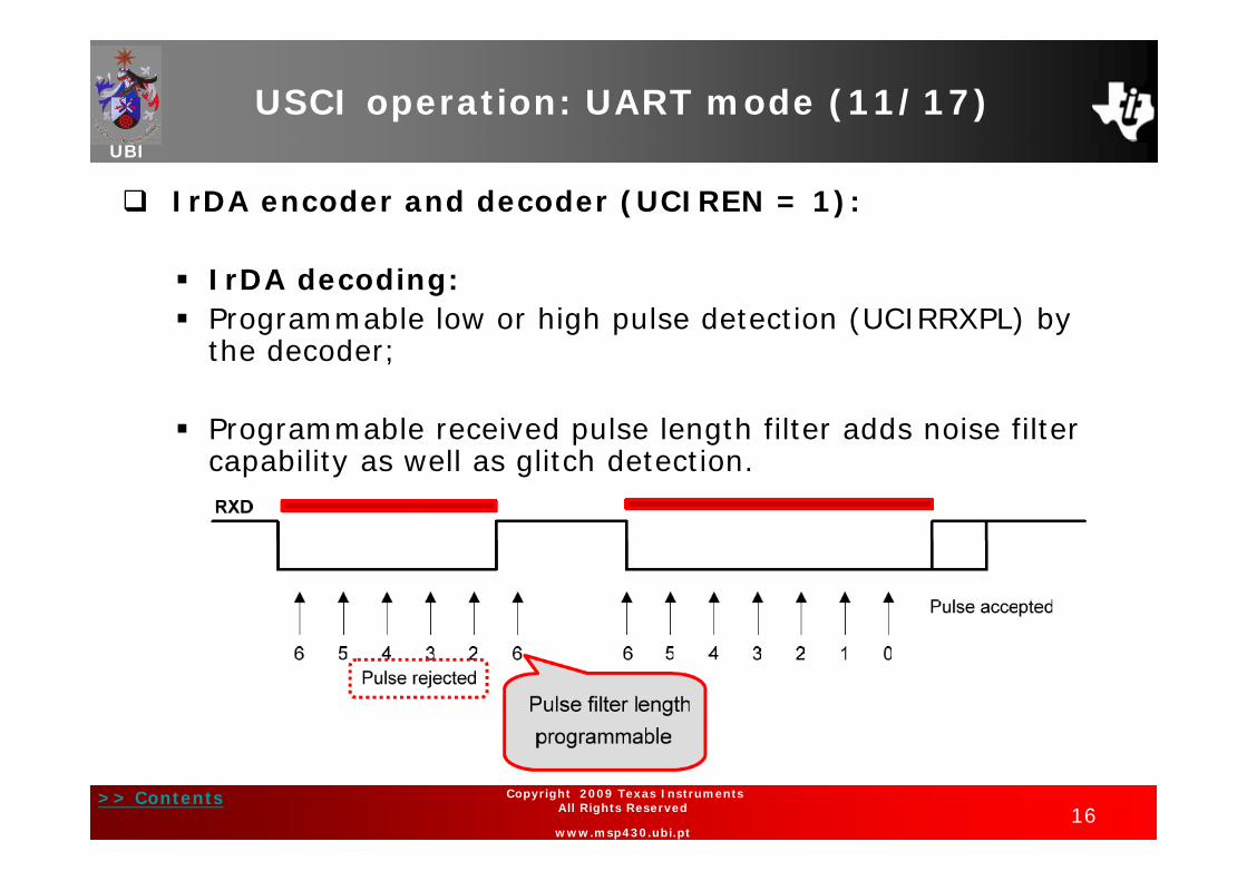
IrDA decoding: Programmable low or high pulse detection (UCIRRXPL) by
th d dthe decoder;
Programmable received pulse length filter adds noise filter g p gcapability as well as glitch detection.
>> Contents16
Copyright 2009 Texas Instruments All Rights Reserved
www.msp430.ubi.pt

USCI operation: UART mode (12/17)UBI
Automatic error detection:Glit h i t th USCI f b i id t ll Glitch suppression prevents the USCI from being accidentally started;
Any pulse on UCAxRXD shorter than the deglitch time y p g(approximately 150 ns) will be ignored.
Framing error UCFE: Set if the stop bit is missing from a i d freceived frame;
Parity error UCPE: Set if there is a parity mismatch in a received frame;received frame;
Receive overrun error UCOE: Set if UCAxRXBUF is overwritten;;
Break condition UCBRK:• Set if all bits in the received frame = 0;
>> Contents17
Copyright 2009 Texas Instruments All Rights Reserved
www.msp430.ubi.pt
• Set the UCAxRXIFG if UCBRKIE bit is set.

USCI operation: UART mode (13/17)UBI
Enable the USCI receive enable bit URXEx:Cl UCSWRST Clear UCSWRST;
The falling edge of the start bit enables the baud rate generator;g ;
If a valid start bit is detected, a character will be received.
USCI transmit enable: Clear UCSWRST; Transmission is initiated by writing data to UCAxTXBUF; Transmission is initiated by writing data to UCAxTXBUF; The baud rate generator is enabled; The data value in UCAxTXBUF is moved to the transmit shift
register on the next BITCLK after the transmit shift register is empty;
UCAxTXIFG is set when a new data value can be written into
>> Contents18
Copyright 2009 Texas Instruments All Rights Reserved
www.msp430.ubi.pt
UCAxTXIFG is set when a new data value can be written into UCAxTXBUF.
USCI operation: UART mode (14/17)UBI
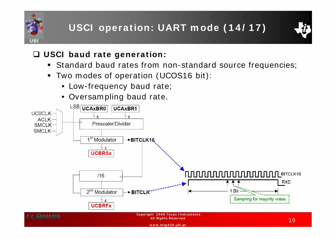
USCI baud rate generation: Standard baud rates from non-standard source frequencies; Standard baud rates from non-standard source frequencies; Two modes of operation (UCOS16 bit):
• Low-frequency baud rate;• Oversampling baud rate.
>> Contents19
Copyright 2009 Texas Instruments All Rights Reserved
www.msp430.ubi.pt

USCI operation: UART mode (15/17)UBI
Transmit bit timing: The timing for each character is the sum of the individual bit The timing for each character is the sum of the individual bit
timings;
A d l i f f h b d d h A modulation feature of the baud rate generator reduces the cumulative bit error.
Two error sources for receive bit timing: Two error sources for receive bit timing: Bit-to-bit timing error;
Error between a start edge occurring and the start edge being accepted by the USCI module.
>> Contents20
Copyright 2009 Texas Instruments All Rights Reserved
www.msp430.ubi.pt
USCI operation: UART mode (16/17)UBI
USCI interrupts:
One interrupt vector for transmission and one interrupt vector for reception:
USCI transmit interrupt operation:• UCAxTXIFG interrupt flag is set by the transmitter to p g y
indicate that UCAxTXBUF is ready to accept another character;
• An interrupt request is generated if UCAxTXIE and GIE are also set;
• UCAxTXIFG is automatically reset if a character is written to UCAxTXBUF.
>> Contents21
Copyright 2009 Texas Instruments All Rights Reserved
www.msp430.ubi.pt

USCI operation: UART mode (17/17)UBI
USCI interrupts (continued):
USCI receive interrupt operation:• UCAxRXIFG interrupt flag is set each time a character is
i d d l d d i UCA RXBUFreceived and loaded into UCAxRXBUF;
• An interrupt request is also generated if UCAxRXIE and p q gGIE are set;
• UCAxRXIFG and UCAxRXIE are reset by a system reset • UCAxRXIFG and UCAxRXIE are reset by a system reset PUC signal or when UCSWRST = 1;
UCA RXIFG i t ti ll t h UCA RXBUF i • UCAxRXIFG is automatically reset when UCAxRXBUF is read.
>> Contents22
Copyright 2009 Texas Instruments All Rights Reserved
www.msp430.ubi.pt

USCI operation: SPI mode (1/9)UBI
Flexible interface: 3 or 4 pin SPI; 3- or 4-pin SPI; 7- or 8-bit data length; Master or slave; LSB or MSB first.
S/W configurable clock phase and polarity;
Programmable SPI master clock;
Double buffered TX/RX; Double buffered TX/RX;
Interrupt driven TX/RX (USCI_A and USCI_B share TX and RX vector););
Direct Memory Address ( DMA) enabled;
LPMx operation
>> Contents23
Copyright 2009 Texas Instruments All Rights Reserved
www.msp430.ubi.pt
LPMx operation.

USCI operation: SPI mode (2/9)UBI
USCI module: SPI mode block diagram:
>> Contents24
Copyright 2009 Texas Instruments All Rights Reserved
www.msp430.ubi.pt

USCI operation: SPI mode (3/9)UBI
USCI module: SPI connections:
>> Contents25
Copyright 2009 Texas Instruments All Rights Reserved
www.msp430.ubi.pt

USCI operation: SPI mode (4/9)UBI
Serial data transmitted and received by multiple devices using a shared clock provided by the master;using a shared clock provided by the master;
Th f i l d f SPI d h Three or four signals are used for SPI data exchange: UCxSIMO: Slave in, master out; UCxSOMI: Slave out, master in;, ; UCxCLK: USCI SPI clock; UCxSTE: Slave transmit enable:
E bl d i t i d t it d t d i • Enables a device to receive and transmit data and is controlled by the master;
• 4 wire master, senses conflicts with other master(s);• In 4 wire slave, externally controls TX and RX.
>> Contents26
Copyright 2009 Texas Instruments All Rights Reserved
www.msp430.ubi.pt

USCI operation: SPI mode (5/9)UBI
USCI initialization/re-configuration process:
Set UCSWRST (BIS.B #UCSWRST,&UCAxCTL1);
Initialize all USCI registers with UCSWRST = 1 (including UCxCTL1);
Configure ports;
Cl UCSWRST i ft (BIC B #UCSWRST &UC CTL1) Clear UCSWRST via software (BIC.B #UCSWRST,&UCxCTL1);
Enable interrupts (optional) via UCxRXIE and/or UCxTXIE.p ( p )
>> Contents27
Copyright 2009 Texas Instruments All Rights Reserved
www.msp430.ubi.pt

USCI operation: SPI mode (6/9)UBI
Define the character format as presented earlier;
Define mode: Master or Slave;
Enable SPI transmit/receive clearing the UCSWRST bit; Enable SPI transmit/receive clearing the UCSWRST bit;
Define serial clock control: UCxCLK is provided by the master on the SPI bus; Configure serial clock polarity and phase (UCCKPL and Configure serial clock polarity and phase (UCCKPL and
UCCKPH bits).
>> Contents28
Copyright 2009 Texas Instruments All Rights Reserved
www.msp430.ubi.pt
USCI operation: SPI mode (7/9)UBI
USCI interrupts:
One interrupt vector for transmission and one interrupt vector for reception:
SPI transmit interrupt operation:• UCxTXIFG interrupt flag is set by the transmitter to p g y
indicate that UCxTXBUF is ready to accept another character;
• An interrupt request is generated if UCxTXIE and GIE are also set;
• UCxTXIFG is automatically reset if the interrupt request is serviced or if a character is written to UCxTXBUF.
>> Contents29
Copyright 2009 Texas Instruments All Rights Reserved
www.msp430.ubi.pt

USCI operation: SPI mode (8/9)UBI
USCI interrupts (continued):
USCI receive interrupt operation:• UCxRXIFG interrupt flag is set each time a character is
i d d l d d i UC RXBUFreceived and loaded into UCxRXBUF;
• An interrupt request is also generated if UCxRXIE and GIE p q gare set;
• UCxRXIFG and UCxRXIE are reset by a system reset PUC • UCxRXIFG and UCxRXIE are reset by a system reset PUC signal or when SWRST = 1;
UC RXIFG i t ti ll t if th di i t t • UCxRXIFG is automatically reset if the pending interrupt is serviced (when UCSWRST = 1) or when UCxRXBUF is read.
>> Contents30
Copyright 2009 Texas Instruments All Rights Reserved
www.msp430.ubi.pt

USCI operation: SPI mode (9/9)UBI
USCI interrupts (continued):
SPI TX interrupt: SPI RX interrupt:
>> Contents31
Copyright 2009 Texas Instruments All Rights Reserved
www.msp430.ubi.pt

USCI operation: I2C mode (1/11)UBI
The I2C mode supports any master or slave I2C-compatible device (Specification v2.1); compatible device (Specification v2.1);
Each I2C device is recognized by a unique address and can operate as either a transmitter or a receiver as well can operate as either a transmitter or a receiver, as well as either the master or the slave;
A master initiates a data transfer and generates the clock signal SCL;
Any device addressed by a master is considered a slave;
Communication using the bi directional serial data (SDA) Communication using the bi-directional serial data (SDA) and serial clock (SCL) pins;
>> Contents32
Copyright 2009 Texas Instruments All Rights Reserved
www.msp430.ubi.pt

USCI operation: I2C mode (2/11)UBI
I2C mode block diagram:
>> Contents33
Copyright 2009 Texas Instruments All Rights Reserved
www.msp430.ubi.pt
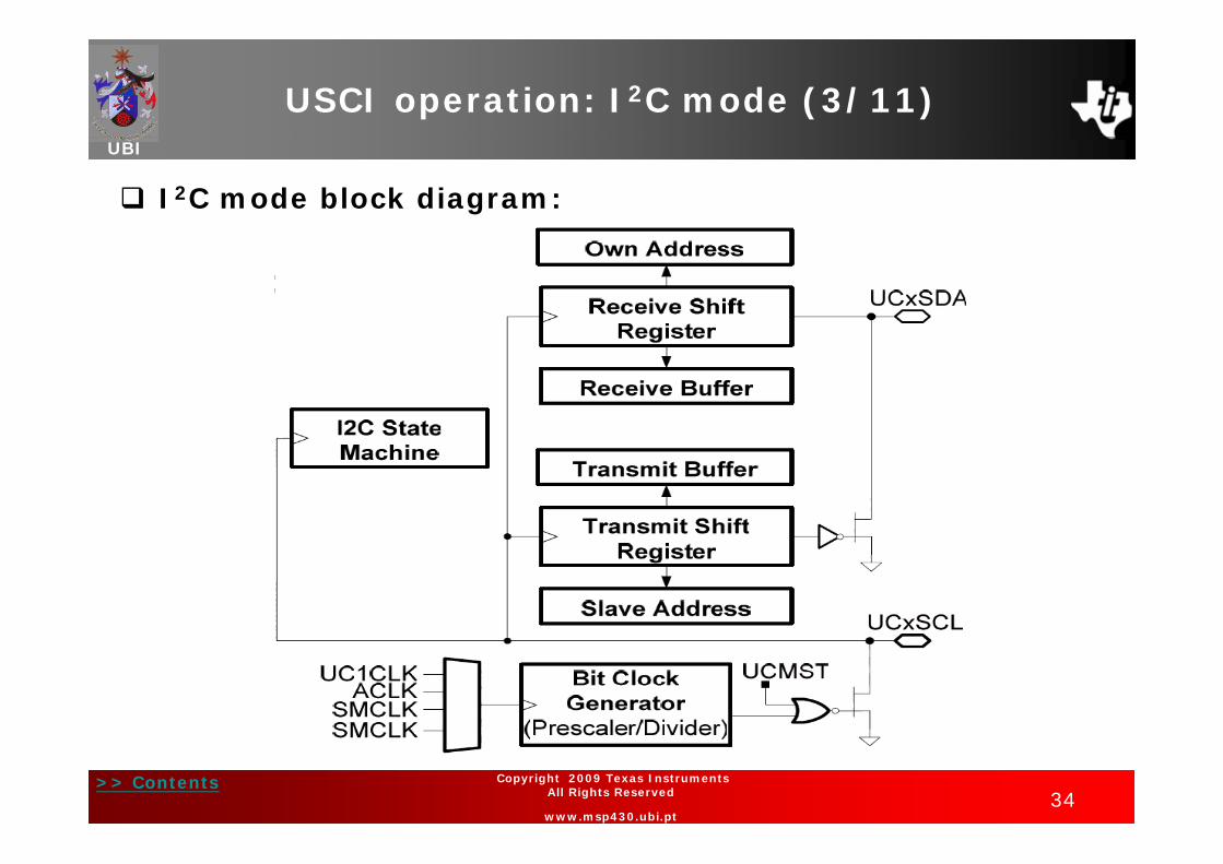
USCI operation: I2C mode (3/11)UBI
I2C mode block diagram:
>> Contents34
Copyright 2009 Texas Instruments All Rights Reserved
www.msp430.ubi.pt

USCI operation: I2C mode (4/11)UBI
Initialized using the sequence given earlier;
I2C serial data: One clock pulse is generated by the master for each data bit
transferred;
Operates with byte data (MSB transferred first);
Th fi t b t ft START diti i t f 7 bit The first byte after a START condition consists of a 7-bit slave address and the R/W bit:• R/W = 0: Master transmits data to a slave;• R/W = 1: Master receives data from a slave.
The ACK bit is sent from the receiver after each byte on the
>> Contents35
Copyright 2009 Texas Instruments All Rights Reserved
www.msp430.ubi.pt
The ACK bit is sent from the receiver after each byte on the 9th SCL clock.

USCI operation: I2C mode (5/11)UBI
I2C addressing modes (7-bit and 10-bit addressing modes);modes);
I2C d l i d I2C module operating modes: Master transmitter; Master receiver;; Slave transmitter; Slave receiver.
Arbitration procedure is invoked if two or more master ptransmitters simultaneously start a transmission on the bus;
>> Contents36
Copyright 2009 Texas Instruments All Rights Reserved
www.msp430.ubi.pt

USCI operation: I2C mode (6/11)UBI
I2C Clock generation and synchronization: SCL is provided by the master on the I2C bus; SCL is provided by the master on the I2C bus; Master mode: BITCLK is provided by the USCI bit clock
generator;Sl d h bi l k i d Slave mode: the bit clock generator is not used.
>> Contents37
Copyright 2009 Texas Instruments All Rights Reserved
www.msp430.ubi.pt

USCI operation: I2C mode (7/11)UBI
I2C interrupts:
One interrupt vector for transmission and one interrupt vector for reception;
I2C transmit interrupt operation:• UCxTXIFG interrupt flag is set by the transmitter to p g y
indicate that UCBxTXBUF is ready to accept another character;
• An interrupt request is also generated if UCxTXIE and GIE are set;
• UCxTXIFG is automatically reset if a character is written to UCxTXBUF or a NACK is received.
>> Contents38
Copyright 2009 Texas Instruments All Rights Reserved
www.msp430.ubi.pt

USCI operation: I2C mode (8/11)UBI
I2C interrupts (continued):
I2C receive interrupt operation:• UCxRXIFG interrupt flag is set each time a character is
i d d l d d i UC RXBUFreceived and loaded into UCxRXBUF;
• An interrupt request is also generated if UCxRXIE and GIE p q gare set;
• UCxRXIFG and UCxRXIE are reset by a system reset PUC • UCxRXIFG and UCxRXIE are reset by a system reset PUC signal or when SWRST = 1;
UC RXIFG i t ti ll t h UC RXBUF i d• UCxRXIFG is automatically reset when UCxRXBUF is read.
>> Contents39
Copyright 2009 Texas Instruments All Rights Reserved
www.msp430.ubi.pt

USCI operation: I2C mode (9/11)UBI
I2C interrupts (continued):
I2C transmit/receive interrupt operation:
>> Contents40
Copyright 2009 Texas Instruments All Rights Reserved
www.msp430.ubi.pt
USCI operation: I2C mode (10/11)UBI
I2C interrupts (continued):
I2C state change interrupt flags:• Arbitration-lost, UCALIFG: Flag is set when two or
i i i i l l more transmitters start a transmission simultaneously, or operates as master but is addressed as a slave by another master;
• Not-acknowledge interrupt, UCNACKIFG: Flag set when an acknowledge is expected but is not received;
• Start condition detected interrupt, UCSTTIFG: Flag set when the I2C module detects a START condition together with its own address while in slave mode;g ;
• Stop condition detected interrupt, UCSTPIFG: Flag set when the I2C module detects a STOP condition while i l d
>> Contents41
Copyright 2009 Texas Instruments All Rights Reserved
www.msp430.ubi.pt
in slave mode.

USCI operation: I2C mode (11/11)UBI
I2C interrupts (continued):
I2C TX interrupt: I2C RX interrupt:
>> Contents42
Copyright 2009 Texas Instruments All Rights Reserved
www.msp430.ubi.pt
USCI registers (UART, SPI and I2C modes)(1/20)
UBI( / )
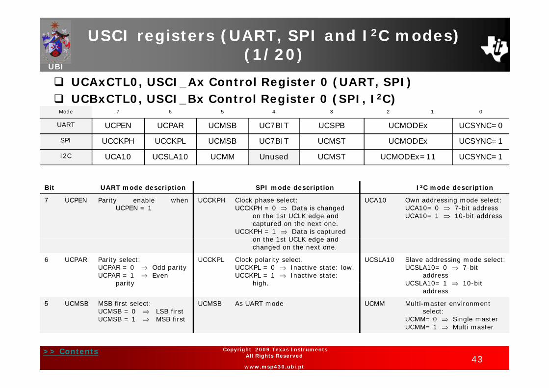
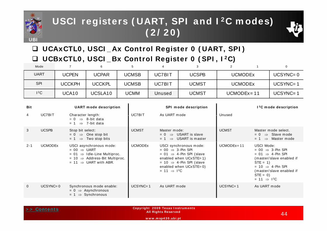
UCAxCTL0, USCI_Ax Control Register 0 (UART, SPI) UCBxCTL0, USCI_Bx Control Register 0 (SPI, I2C)
Mode 7 6 5 4 3 2 1 0
UART UCPEN UCPAR UCMSB UC7BIT UCSPB UCMODEx UCSYNC=0
SPI UCCKPH UCCKPL UCMSB UC7BIT UCMST UCMODEx UCSYNC=1
I2C UCA10 UCSLA10 UCMM Unused UCMST UCMODEx=11 UCSYNC=1
Bit UART mode description SPI mode description I2C mode description
7 UCPEN Parity enable whenUCPEN = 1
UCCKPH Clock phase select:UCCKPH = 0 Data is changed
on the 1st UCLK edge and captured on the next one.
UCCKPH = 1 Data is captured on the 1st UCLK edge and
UCA10 Own addressing mode select:UCA10= 0 7-bit addressUCA10= 1 10-bit address
on the 1st UCLK edge and changed on the next one.
6 UCPAR Parity select:UCPAR = 0 Odd parityUCPAR = 1 Even
parity
UCCKPL Clock polarity select.UCCKPL = 0 Inactive state: low.UCCKPL = 1 Inactive state:
high
UCSLA10 Slave addressing mode select:UCSLA10= 0 7-bit
addressUCSLA10 1 10 bit parity high. UCSLA10= 1 10-bit
address
5 UCMSB MSB first select:UCMSB = 0 LSB firstUCMSB = 1 MSB first
UCMSB As UART mode UCMM Multi-master environment select:
UCMM= 0 Single masterUCMM 1 Multi master
>> Contents43
Copyright 2009 Texas Instruments All Rights Reserved
www.msp430.ubi.pt
UCMM= 1 Multi master
USCI registers (UART, SPI and I2C modes)(2/20)
UBI( / )
UCAxCTL0, USCI_Ax Control Register 0 (UART, SPI) UCBxCTL0, USCI_Bx Control Register 0 (SPI, I2C)
Mode 7 6 5 4 3 2 1 0
UART UCPEN UCPAR UCMSB UC7BIT UCSPB UCMODEx UCSYNC=0
SPI UCCKPH UCCKPL UCMSB UC7BIT UCMST UCMODEx UCSYNC=1
I2C UCA10 UCSLA10 UCMM Unused UCMST UCMODEx=11 UCSYNC=1
Bit UART mode description SPI mode description I2C mode description
4 UC7BIT Character length: UC7BIT As UART mode Unused4 UC7BIT Character length:= 0 8-bit data= 1 7-bit data
UC7BIT As UART mode Unused
3 UCSPB Stop bit select:= 0 One stop bit= 1 Two stop bits
UCMST Master mode:= 0 USART is slave= 1 USART is master
UCMST Master mode select.= 0 Slave mode= 1 Master mode
2-1 UCMODEx USCI asynchronous mode:= 00 UART= 01 Idle-Line Multiproc.= 10 Address-Bit Multiproc.= 11 UART with ABR.
UCMODEx USCI synchronous mode:= 00 3-Pin SPI= 01 4-Pin SPI (slave enabled when UCxSTE=1)= 10 4-Pin SPI (slave enabled when UCxSTE=0)
UCMODEx=11 USCI Mode:= 00 3-Pin SPI= 01 4-Pin SPI (master/slave enabled if STE = 1)= 10 4-Pin SPI )
= 11 I2C (master/slave enabled if STE = 0)= 11 I2C
0 UCSYNC=0 Synchronous mode enable:= 0 Asynchronous= 1 Synchronous
UCSYNC=1 As UART mode UCSYNC=1 As UART mode
>> Contents44
Copyright 2009 Texas Instruments All Rights Reserved
www.msp430.ubi.pt
= 1 Synchronous

USCI registers (UART, SPI and I2C modes)(3/20)
UBI( / )
UCAxCTL1, USCI_Ax Control Register 1 (UART, SPI) UCBxCTL1, USCI_Bx Control Register 1 (SPI, I2C)
Mode 7 6 5 4 3 2 1 0
UART UCSSELx UCRXEIE UCBRKIE UCDORM UCTXADDR UCTXBRK UCSWRST
SPI UCSSELx Unused Unused Unused Unused Unused UCSWRST
I2C UCSSELx Unused UCTR UCTXNACK UCTXSTP UCTXSTT UCSWRSTI C UCSSELx Unused UCTR UCTXNACK UCTXSTP UCTXSTT UCSWRST
Bit UART mode description SPI mode description I2C mode descriptionBit UART mode description SPI mode description I C mode description
7-6 UCSSELx BRCLK source clock:= 00 UCLK= 01 ACLK= 10 SMCLK
UCSSELx BRCLK source clock:= 00 N/A= 01 ACLK= 10 SMCLK
UCSSELx BRCLK source clock:= 00 UCLKI= 01 ACLK= 10 SMCLK10 SMCLK
= 11 SMCLK 10 SMCLK
= 11 SMCLK 10 SMCLK
= 11 SMCLK
5 UCRXEIE Receive erroneous-character IE:= 0 Rejected (UCAxRXIFG not set)= 1 Received (UCAxRXIFG set)
Unused Unused Slave addressing mode select:UCSLA10= 0 7-bit addressUCSLA10= 1 10-bit UCSLA10= 1 10 bit address
4 UCBRKIE Receive break character IE:= 0 Not set UCAxRXIFG.= 1 Set UCAxRXIFG.
Unused UCTR Transmitter/Receiver select:= 0 Receiver= 1 Transmitter
>> Contents45
Copyright 2009 Texas Instruments All Rights Reserved
www.msp430.ubi.pt

USCI registers (UART, SPI and I2C modes)(4/20)
UBI( / )
UCAxCTL1, USCI_Ax Control Register 1 (UART, SPI) UCBxCTL1, USCI_Bx Control Register 1 (SPI, I2C)
Mode 7 6 5 4 3 2 1 0
UART UCSSELx UCRXEIE UCBRKIE UCDORM UCTXADDR UCTXBRK UCSWRST
SPI UCSSELx Unused Unused Unused Unused Unused UCSWRST
I2C UCSSELx Unused UCTR UCTXNACK UCTXSTP UCTXSTT UCSWRSTI C UCSSELx Unused UCTR UCTXNACK UCTXSTP UCTXSTT UCSWRST
Bit UART mode description SPI mode description
I2C mode descriptionp
3 UCDORM Dormant. Puts USCI into sleep mode:= 0 Not dormant= 1 Dormant
Unused UCTXNACK Transmit a NACK:= 0 Acknowledge normally= 1 Generate NACK
2 UCTXADDR Transmit address: Unused UCTXSTP Transmit STOP condition in master = 0 Next frame transmitted is data= 1 Next frame transmitted is address
mode:= 0 No STOP generated= 1 Generate STOP
1 UCTXBRK Transmit break:= 0 Next frame transmitted is not a break
Unused UCTXSTT Transmit START condition in master mode:= 0 No START generatedbreak
= 1 Next frame transmitted is a break or a break/synch
0 No START generated= 1 Generate START
0 UCSWRST Software reset enable=0 Disabled. USCI reset released for operation1 E bl d USCI l i h ld i t
UCSWRST As UART mode UCSWRST As UART mode
>> Contents46
Copyright 2009 Texas Instruments All Rights Reserved
www.msp430.ubi.pt
1 Enabled. USCI logic held in reset state

USCI registers (UART, SPI and I2C modes) (5/20)
UBI( / )
UCAxBR0, USCI_Ax Baud Rate Control Register 0 (UART, SPI) UCBxBR0, USCI_Bx Bit Rate Control Register 0 (SPI, I2C)
Mode 7 6 5 4 3 2 1 0
UART / SPI / I2C UCBRx – low byte
UCAxBR1, USCI_Ax Baud Rate Control Register 1 (UART, SPI) UCBxBR1, USCI_Bx Bit Rate Control Register 1 (SPI, I2C)
Mode 7 6 5 4 3 2 1 0Mode 7 6 5 4 3 2 1 0
UART / SPI / I2C UCBRx – high byte
Bit UART mode description SPI mode description I2C mode descriptiondescription
7-6 UCBRx Clock prescaler setting of the baud rate generator:Prescaler value (16-bit value) =
UCBRx Bit clock prescaler setting:Prescaler value (16-bit value) ={UCAxBR0+UCAxBR1×256}
UCBRx As SPI mode
>> Contents47
Copyright 2009 Texas Instruments All Rights Reserved
www.msp430.ubi.pt
){UCAxBR0+UCAxBR1x256}
{ }
USCI registers (UART, SPI and I2C modes) (6/20)
UBI( / )
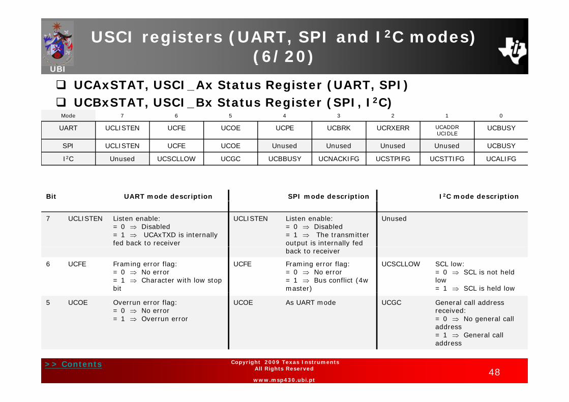
UCAxSTAT, USCI_Ax Status Register (UART, SPI) UCBxSTAT, USCI_Bx Status Register (SPI, I2C)
Mode 7 6 5 4 3 2 1 0
UART UCLISTEN UCFE UCOE UCPE UCBRK UCRXERR UCADDR UCIDLE
UCBUSY
SPI UCLISTEN UCFE UCOE Unused Unused Unused Unused UCBUSY
I2C Unused UCSCLLOW UCGC UCBBUSY UCNACKIFG UCSTPIFG UCSTTIFG UCALIFG
Bit UART mode description SPI mode description I2C mode description
7 UCLISTEN Listen enable:= 0 Disabled= 1 UCAxTXD is internally fed back to receiver
UCLISTEN Listen enable:= 0 Disabled= 1 The transmitter output is internally fed
Unused
back to receiver
6 UCFE Framing error flag:= 0 No error= 1 Character with low stop bit
UCFE Framing error flag:= 0 No error= 1 Bus conflict (4w master)
UCSCLLOW SCL low:= 0 SCL is not held low= 1 SCL is held low
5 UCOE Overrun error flag:= 0 No error= 1 Overrun error
UCOE As UART mode UCGC General call address received:= 0 No general call address= 1 General call
>> Contents48
Copyright 2009 Texas Instruments All Rights Reserved
www.msp430.ubi.pt
address

USCI registers (UART, SPI and I2C modes) (7/20)
UBI( / )
UCAxSTAT, USCI_Ax Status Register (UART, SPI) UCBxSTAT, USCI_Bx Status Register (SPI, I2C)
Mode 7 6 5 4 3 2 1 0
UART UCLISTEN UCFE UCOE UCPE UCBRK UCRXERR UCADDR UCIDLE
UCBUSY
SPI UCLISTEN UCFE UCOE Unused Unused Unused Unused UCBUSY
I2C Unused UCSCLLOW UCGC UCBBUSY UCNACKIFG UCSTPIFG UCSTTIFG UCALIFG
Bit UART mode description SPI mode description I2C mode description
4 UCPE Parity error flag: Unused UCBBUSY Bus busy:4 UCPE Parity error flag:= 0 No error= 1 Character with parity error
Unused UCBBUSY Bus busy:= 0 Bus inactive= 1 Bus busy
3 UCBRK Break detect flag:= 0 No break condition= 1 Break condition occurred
Unused UCNACKIFG NACK received interrupt flag:= 0 No interrupt pending= 1 Interrupt pending
2 UCRXERR Receive error flag.= 0 No receive errors detected= 1 Receive error detected
Unused UCSTPIFG Stop condition interrupt flag:= 0 No interrupt pending= 1 Interrupt pending
1 UCADDRUCIDLE
Address-bit multiproc. mode:= 0 Received character is data
Unused UCSTTIFG Start condition interrupt flag:= 0 No interrupt pending
= 1 Received character is an addressIdle-line multiproc. mode:= 0 No idle line detected= 1 Idle line detected
= 1 Interrupt pending
0 UCBUSY USCI busy: UCBUSY UCALIFG Arbitration lost interrupt flag:
>> Contents49
Copyright 2009 Texas Instruments All Rights Reserved
www.msp430.ubi.pt
0 UCBUSY USCI busy:= 0 USCI inactive= 1 USCI transmit/receive
UCBUSY UCALIFG Arbitration lost interrupt flag:= 0 No interrupt pending= 1 Interrupt pending
USCI registers (UART, SPI and I2C modes) (8/20)
UBI( / )
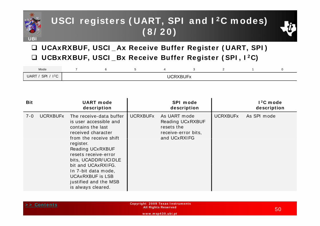
UCAxRXBUF, USCI_Ax Receive Buffer Register (UART, SPI) UCBxRXBUF, USCI_Bx Receive Buffer Register (SPI, I2C)
Mode 7 6 5 4 3 2 1 0
UART / SPI / I2C UCRXBUFx
Bit UART mode description
SPI mode description
I2C mode description
7-0 UCRXBUFx The receive-data buffer is user accessible and contains the last received character from the receive shift
UCRXBUFx As UART modeReading UCxRXBUF resets thereceive-error bits, and UCxRXIFG
UCRXBUFx As SPI mode
from the receive shift register.Reading UCxRXBUF resets receive-error bits, UCADDR/UCIDLE bit and UCAxRXIFG
and UCxRXIFG
bit and UCAxRXIFG.In 7-bit data mode, UCAxRXBUF is LSB justified and the MSB is always cleared.
>> Contents50
Copyright 2009 Texas Instruments All Rights Reserved
www.msp430.ubi.pt
USCI registers (UART, SPI and I2C modes) (9/20)
UBI( / )
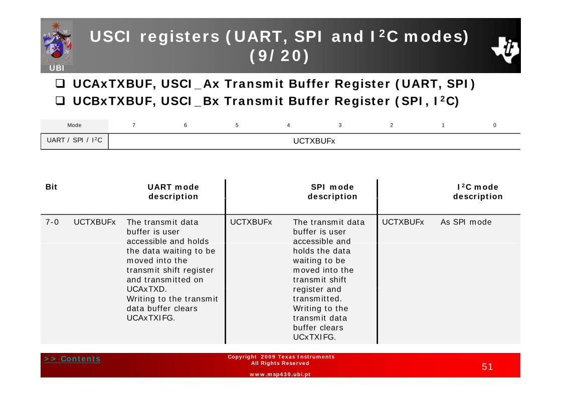
UCAxTXBUF, USCI_Ax Transmit Buffer Register (UART, SPI) UCBxTXBUF, USCI_Bx Transmit Buffer Register (SPI, I2C)
Mode 7 6 5 4 3 2 1 0
UART / SPI / I2C UCTXBUFx
Bit UART mode description
SPI mode description
I2C mode descriptiondescription description description
7-0 UCTXBUFx The transmit data buffer is user accessible and holds
UCTXBUFx The transmit data buffer is user accessible and
UCTXBUFx As SPI mode
accessible and holds the data waiting to be moved into the transmit shift register and transmitted on UCAxTXD
accessible and holds the data waiting to be moved into the transmit shift register and UCAxTXD.
Writing to the transmit data buffer clears UCAxTXIFG.
register and transmitted.Writing to the transmit data buffer clears
>> Contents51
Copyright 2009 Texas Instruments All Rights Reserved
www.msp430.ubi.pt
UCxTXIFG.

USCI registers (UART, SPI and I2C modes) (10/20)
UBI( / )
IE2, Interrupt Enable Register 2 (UART, SPI, I2C)Mode 7 6 5 4 3 2 1 0
UART UCA0TXIE UCA0RXIEUART UCA0TXIE UCA0RXIE
SPI UCB0TXIE UCB0RXIE UCA0TXIE UCA0RXIE
I2C UCB0TXIE UCB0RXIE
Bit UART mode description
SPI mode description
I2C mode description
3 UCB0TXIE USCI_B0 transmit interrupt enable:
UCB0TXIE As SPI mode
= 0 Disabled= 1 Enabled
2 UCB0RXIE USCI_B0 receive interrupt enable:
0 Di bl d
UCB0RXIE As SPI mode
= 0 Disabled= 1 Enabled
1 UCA0TXIE USCI_A0 transmit interrupt enable:= 0 Disabled
UCA0TXIE As UART mode
= 0 Disabled= 1 Enabled
0 UCA0RXIE USCI_A0 receive interrupt enable:= 0 Disabled
UCA0RXIE As UART mode
>> Contents52
Copyright 2009 Texas Instruments All Rights Reserved
www.msp430.ubi.pt
0 Disabled= 1 Enabled
USCI registers (UART, SPI and I2C modes) (11/20)
UBI( / )
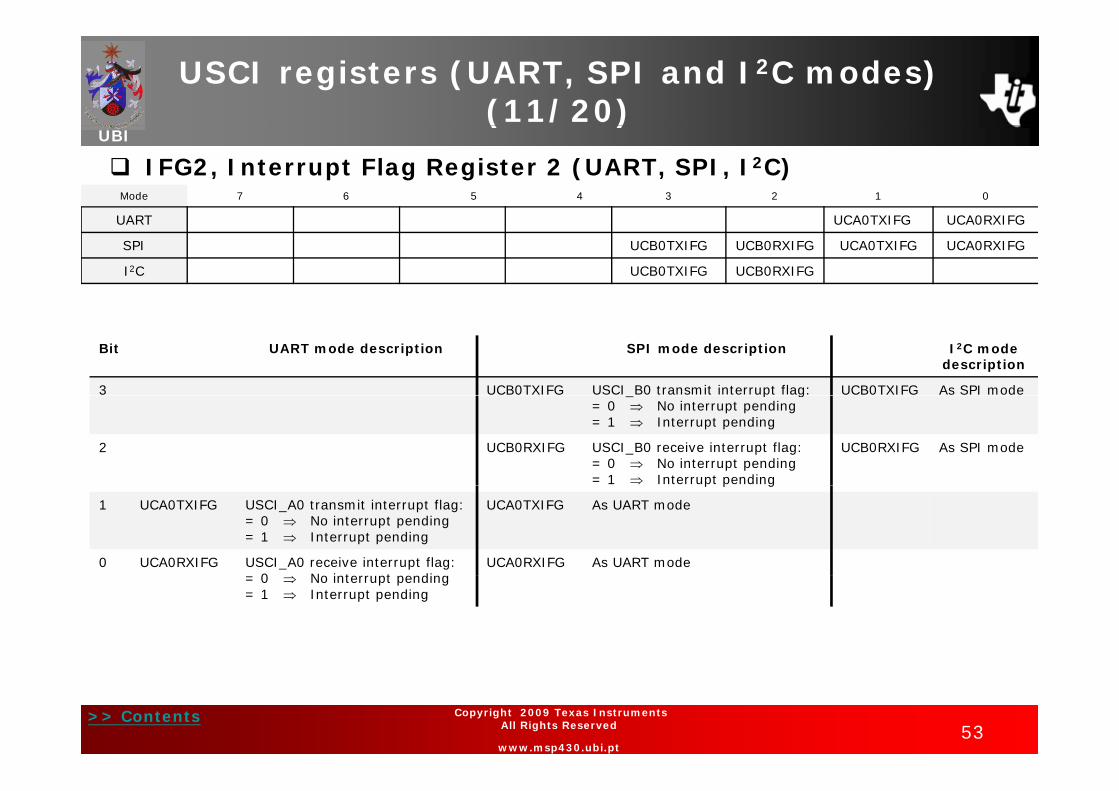
IFG2, Interrupt Flag Register 2 (UART, SPI, I2C)Mode 7 6 5 4 3 2 1 0
UART UCA0TXIFG UCA0RXIFGUART UCA0TXIFG UCA0RXIFG
SPI UCB0TXIFG UCB0RXIFG UCA0TXIFG UCA0RXIFG
I2C UCB0TXIFG UCB0RXIFG
Bit UART mode description SPI mode description I2C mode description
3 UCB0TXIFG USCI B0 transmit interrupt flag: UCB0TXIFG As SPI mode_ p g= 0 No interrupt pending= 1 Interrupt pending
2 UCB0RXIFG USCI_B0 receive interrupt flag:= 0 No interrupt pending= 1 Interrupt pending
UCB0RXIFG As SPI mode
p p g
1 UCA0TXIFG USCI_A0 transmit interrupt flag:= 0 No interrupt pending= 1 Interrupt pending
UCA0TXIFG As UART mode
0 UCA0RXIFG USCI_A0 receive interrupt flag: 0 N i t t di
UCA0RXIFG As UART mode= 0 No interrupt pending= 1 Interrupt pending
>> Contents53
Copyright 2009 Texas Instruments All Rights Reserved
www.msp430.ubi.pt

USCI registers (UART, SPI and I2C modes) (12/20)
UBI( / )
UC1IE, USCI_A1 Interrupt Enable Register (UART, SPI) UC1IE, USCI_B1 Interrupt Enable Register (SPI, I2C)
Mode 7 6 5 4 3 2 1 0
UART Unused Unused Unused Unused UCA1TXIE UCA1RXIE
SPI Unused Unused Unused Unused UCB1TXIE UCB1RXIE UCA1TXIE UCA1RXIE
I2C Unused Unused Unused Unused UCB1TXIE UCB1RXIE
Bit UART mode description SPI mode description I2C mode description
3 UCB1TXIE USCI_B1 transmit interrupt enable:UTXIE1 = 0 DisabledUTXIE1 1 E bl d
UCB1TXIE As SPI mode
UTXIE1 = 1 Enabled
2 UCB1RXIE USCI_B1 receive interrupt enable:URXIE1 = 0 DisabledURXIE1 = 1 Enabled
UCB1RXIE As SPI mode
1 UCA1TXIE USCI A1 transmit interrupt UCA1TXIE As UART mode1 UCA1TXIE USCI_A1 transmit interrupt enable:UTXIE1 = 0 DisabledUTXIE1 = 1 Enabled
UCA1TXIE As UART mode
0 UCA1RXIE USCI_A1 receive interrupt enable:
UCA1RXIE As UART mode
>> Contents54
Copyright 2009 Texas Instruments All Rights Reserved
www.msp430.ubi.pt
URXIE1 = 0 DisabledURXIE1 = 1 Enabled

USCI registers (UART, SPI and I2C modes) (13/20)
UBI( / )
UC1IFG, USCI_A1 Interrupt Flag Register (UART, SPI) UC1IFG, USCI_B1 Interrupt Flag Register (SPI, I2C)
Mode 7 6 5 4 3 2 1 0
UART UCA1TXIFG UCA1RXIFG
SPI UCB1TXIFG UCB1RXIFG UCA1TXIFG UCA1RXIFG
I2C UCB1TXIFG UCB1RXIFG
Bit UART mode description SPI mode description I2C mode descriptionBit UART mode description SPI mode description I C mode description
3 UCB1TXIFG USCI_B1 transmit interrupt flag:= 0 No interrupt pending= 1 Interrupt pending
UCB1TXIFG As SPI mode
2 UCB1RXIFG USCI_B1 receive interrupt flag:= 0 No interrupt pending= 1 Interrupt pending
UCB1RXIFG As SPI mode
1 UCA1TXIFG USCI A1 transmit interrupt flag: UCA1TXIFG As UART modeUC G U _ a up ag= 0 No interrupt pending= 1 Interrupt pending
UC G s U ode
0 UCA1RXIFG USCI_A1 receive interrupt flag:= 0 No interrupt pending= 1 Interrupt pending
UCA1RXIFG As UART mode
>> Contents55
Copyright 2009 Texas Instruments All Rights Reserved
www.msp430.ubi.pt

USCI registers (UART, SPI and I2C modes) (14/20)
UBI( / )
UCAxMCTL, USCI_Ax Modulation Control Register (UART)7 6 5 4 3 2 1 0
UCBRFx UCBRSx UCOS16
Bit UART mode descriptionBit UART mode description
7-4 UCBRFx First modulation pattern for BITCLK16 when UCOS16 = 1(See Table 19-3 of the MSP430x4xx User’s Guide)
3-1 UCBRSx Second modulation pattern for BITCLK(See Table 19 2 of the MSP430x4xx User’s Guide)(See Table 19-2 of the MSP430x4xx User s Guide)
0 UCOS16 Oversampling mode enabled when UCOS16 = 1
>> Contents56
Copyright 2009 Texas Instruments All Rights Reserved
www.msp430.ubi.pt

USCI registers (UART, SPI and I2C modes) (15/20)
UBI( / )
UCAxIRTCTL, USCI_Ax IrDA Transmit Control Register (UART)7 6 5 4 3 2 1 0
UCIRTXPLx UCIRTXCLK UCIREN
Bit UART mode descriptionBit UART mode description
7-2 UCIRTXPLx Transmit pulse length:tPULSE = (UCIRTXPLx + 1) / (2 x fIRTXCLK)
1 UCIRTXCLK IrDA transmit pulse clock select:UCIRTXCLK = 0 BRCLKUCIRTXCLK = 1 BITCLK16, when UCOS16 = 1
BRCLK, otherwise
0 UCIREN IrDA encoder/decoder enable:UCIREN 0 I DA d /d d di bl dUCIREN = 0 IrDA encoder/decoder disabledUCIREN = 1 IrDA encoder/decoder enabled
>> Contents57
Copyright 2009 Texas Instruments All Rights Reserved
www.msp430.ubi.pt

USCI registers (UART, SPI and I2C modes) (16/20)
UBI( / )
UCAxIRRCTL, USCI_Ax IrDA Receive Control Register (UART)7 6 5 4 3 2 1 0
UCIRRXFLx UCIRRXPL UCIRRXFE
Bit UART d d i tiBit UART mode description
7-2 UCIRRXFLx Receive filter length (minimum pulse length):tMIN = (UCIRRXFLx + 4) / (2 × fIRTXCLK)
1 UCIRRXPL IrDA receive input UCAxRXD polarity When a light pulse is seen:1 UCIRRXPL IrDA receive input UCAxRXD polarity. When a light pulse is seen:UCIRRXPL = 0 IrDA transceiver delivers a high pulse UCIRRXPL = 1 IrDA transceiver delivers a low pulse
0 UCIRRXFE IrDA receive filter enabled:UCIRRXFE = 0 DisabledUCIRRXFE = 1 Enabled
>> Contents58
Copyright 2009 Texas Instruments All Rights Reserved
www.msp430.ubi.pt
USCI registers (UART, SPI and I2C modes) (17/20)
UBI( / )
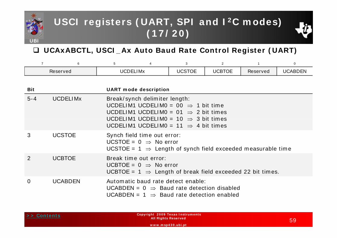
UCAxABCTL, USCI_Ax Auto Baud Rate Control Register (UART)
7 6 5 4 3 2 1 0
Reserved UCDELIMx UCSTOE UCBTOE Reserved UCABDEN
Bit UART mode descriptionp
5-4 UCDELIMx Break/synch delimiter length:UCDELIM1 UCDELIM0 = 00 1 bit timeUCDELIM1 UCDELIM0 = 01 2 bit timesUCDELIM1 UCDELIM0 = 10 3 bit timesUCDELIM1 UCDELIM0 = 10 3 bit timesUCDELIM1 UCDELIM0 = 11 4 bit times
3 UCSTOE Synch field time out error:UCSTOE = 0 No errorUCSTOE = 1 Length of synch field exceeded measurable time
2 UCBTOE Break time out error:UCBTOE = 0 No errorUCBTOE = 1 Length of break field exceeded 22 bit times.UCBTOE 1 Length of break field exceeded 22 bit times.
0 UCABDEN Automatic baud rate detect enable:UCABDEN = 0 Baud rate detection disabledUCABDEN = 1 Baud rate detection enabled
>> Contents59
Copyright 2009 Texas Instruments All Rights Reserved
www.msp430.ubi.pt
USCI registers (UART, SPI and I2C modes) (18/20)
UBI( / )
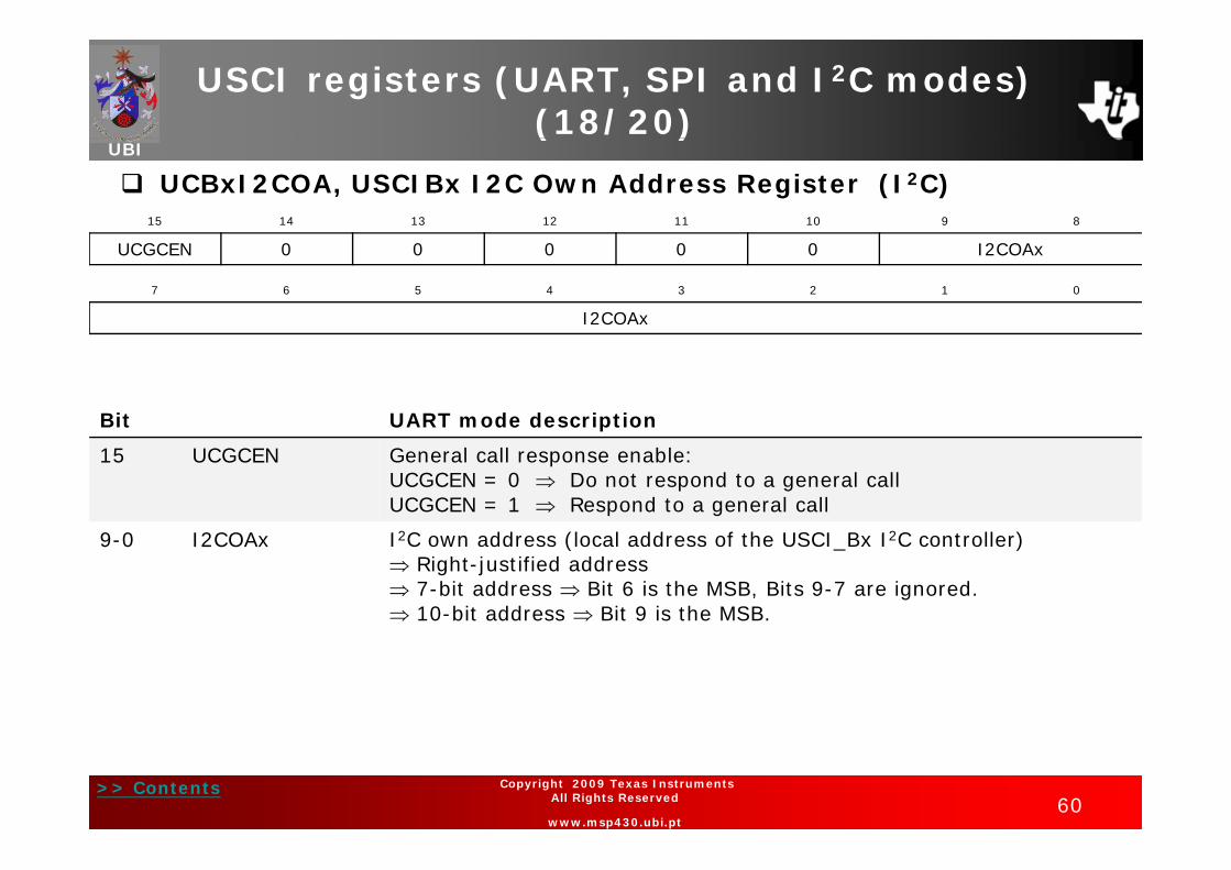
UCBxI2COA, USCIBx I2C Own Address Register (I2C)15 14 13 12 11 10 9 8
UCGCEN 0 0 0 0 0 I2COAx
7 6 5 4 3 2 1 0
I2COAx
Bit UART mode description
15 UCGCEN General call response enable:UCGCEN = 0 Do not respond to a general callUCGCEN = 1 Respond to a general call
9 0 I2COA I2C dd (l l dd f th USCI B I2C t ll )9-0 I2COAx I2C own address (local address of the USCI_Bx I2C controller) Right-justified address 7-bit address Bit 6 is the MSB, Bits 9-7 are ignored. 10-bit address Bit 9 is the MSB.
>> Contents60
Copyright 2009 Texas Instruments All Rights Reserved
www.msp430.ubi.pt

USCI registers (UART, SPI and I2C modes) (19/20)
UBI( / )
UCBxI2CSA, USCI_Bx I2C Slave Address Register (I2C)15 14 13 12 11 10 9 8
0 0 0 0 0 0 I2CSAx
7 6 5 4 3 2 1 0
I2CSAx
Bit UART mode description
9-0 I2CSAx I2C slave address (slave address of the external device to be addressed by the USCI_Bx module) Only used in master mode Right-justified address Right justified address 7-bit address Bit 6 is the MSB, Bits 9-7 are ignored. 10-bit address Bit 9 is the MSB.
>> Contents61
Copyright 2009 Texas Instruments All Rights Reserved
www.msp430.ubi.pt

USCI registers (UART, SPI and I2C modes) (20/20)
UBI( / )
UCBxI2CIE, USCI_Bx I2C Interrupt Enable Register (I2C)
7 6 5 4 3 2 1 0
Reserved UCNACKIE UCSTPIE UCSTTIE UCALIE
Bit UART mode descriptionBit UART mode description
3 UCNACKIE Not-acknowledge interrupt enable:UCNACKIE = 0 Interrupt disabledUCNACKIE = 1 Interrupt enabledp
2UCSTPIE
Stop condition interrupt enable:UCSTPIE = 0 Interrupt disabledUCSTPIE = 1 Interrupt enabled
1 St t diti i t t bl1UCSTTIE
Start condition interrupt enable:UCSTTIE = 0 Interrupt disabledUCSTTIE = 1 Interrupt enabled
0UCALIE
Arbitration lost interrupt enable:UCALIE 0 I t t di bl dUCALIE UCALIE = 0 Interrupt disabledUCALIE = 1 Interrupt enabled
>> Contents62
Copyright 2009 Texas Instruments All Rights Reserved
www.msp430.ubi.pt