lecture 04 design of rc members for shea and torsion
TRANSCRIPT

1
Department of Civil Engineering, University of Engineering and Technology Peshawar, Pakistan
Prof. Dr. Qaisar Ali CE 5115 Advance Design of Reinforced Concrete Structures
Lecture-04Design of RC Members for
Shear and Torsion
1
By: Prof Dr. Qaisar Ali
Civil Engineering Department
www.drqaisarali.com
Department of Civil Engineering, University of Engineering and Technology Peshawar, Pakistan
Prof. Dr. Qaisar Ali CE 5115 Advance Design of Reinforced Concrete Structures 2
Topics Addressed
� Design of RC Members for Shear� Shear Stresses in Rectangular Beams
� Diagonal Tension in RC Beams Subjected to Flexure and ShearLoading
� Types of Cracks in RC Beams
� Shear Strength of Concrete
� Web Reinforcement Requirement
� ACI Code Provisions for Shear Design
� Effect of Axial Force on Shear Strength of Concrete
2
Department of Civil Engineering, University of Engineering and Technology Peshawar, Pakistan
Prof. Dr. Qaisar Ali CE 5115 Advance Design of Reinforced Concrete Structures 3
Topics Addressed
� Design of RC Members for Torsion
� Torsional Stresses in Solid Concrete Members
� Torsional Strength of Concrete
� Reinforcement Requirement
� ACI Requirements for Design of RC Members Subjected toTorsion
� Steps for Design of RC Member Subjected to Torsion
� Example
Department of Civil Engineering, University of Engineering and Technology Peshawar, Pakistan
Prof. Dr. Qaisar Ali CE 5115 Advance Design of Reinforced Concrete Structures
Design of RC Members for Shear
4
3
Department of Civil Engineering, University of Engineering and Technology Peshawar, Pakistan
Prof. Dr. Qaisar Ali CE 5115 Advance Design of Reinforced Concrete Structures
Shear Stresses in Rectangular
Beams
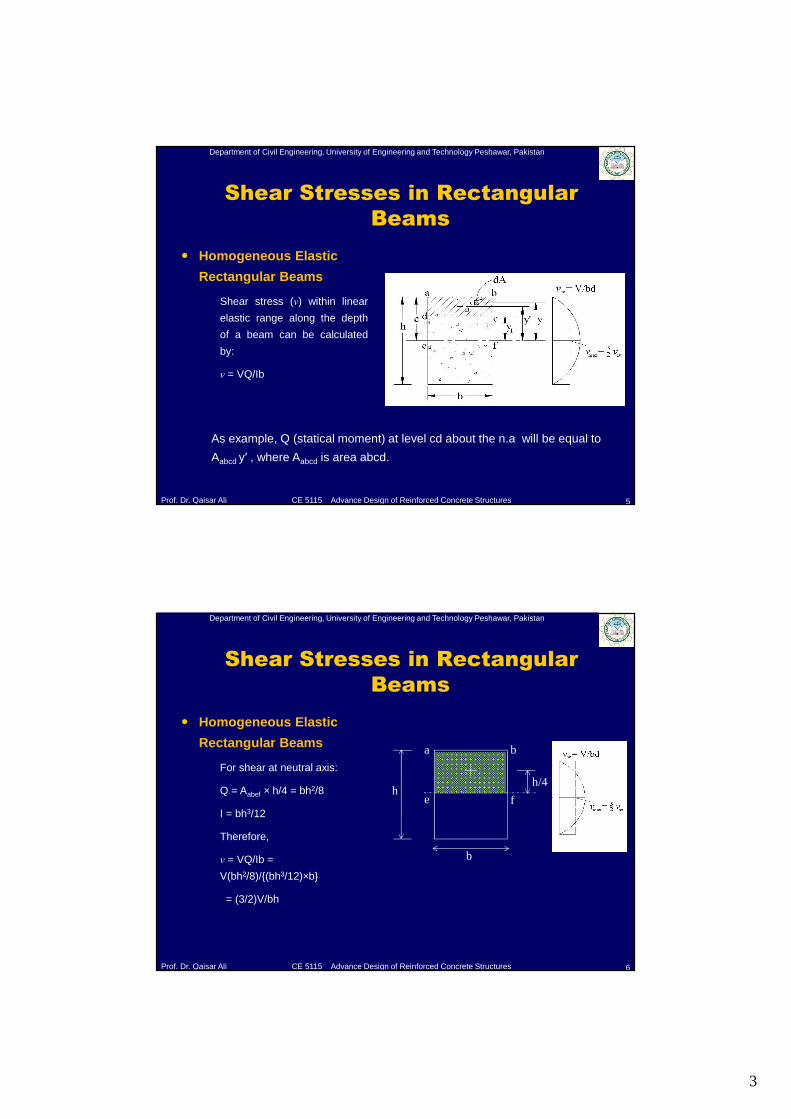
� Homogeneous Elastic
Rectangular Beams
Shear stress (ν) within linear
elastic range along the depth
of a beam can be calculated
by:
ν = VQ/Ib
5
As example, Q (statical moment) at level cd about the n.a will be equal to
Aabcd y′ , where Aabcd is area abcd.
Department of Civil Engineering, University of Engineering and Technology Peshawar, Pakistan
Prof. Dr. Qaisar Ali CE 5115 Advance Design of Reinforced Concrete Structures
Shear Stresses in Rectangular
Beams
6
a b
e fh
b
h/4
� Homogeneous Elastic
Rectangular Beams
For shear at neutral axis:
Q = Aabef × h/4 = bh2/8
I = bh3/12
Therefore,
ν = VQ/Ib =
V(bh2/8)/{(bh3/12)×b}
= (3/2)V/bh
4
Department of Civil Engineering, University of Engineering and Technology Peshawar, Pakistan
Prof. Dr. Qaisar Ali CE 5115 Advance Design of Reinforced Concrete Structures
Shear Stresses in Rectangular
Beams
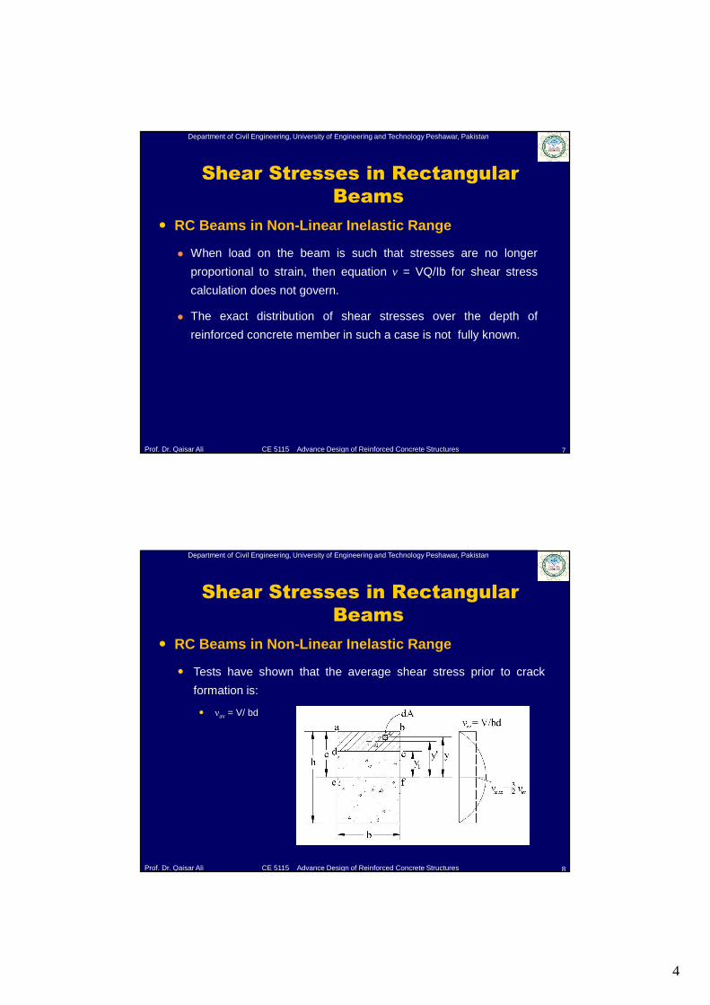
� RC Beams in Non-Linear Inelastic Range
� When load on the beam is such that stresses are no longer
proportional to strain, then equation v = VQ/Ib for shear stress
calculation does not govern.
� The exact distribution of shear stresses over the depth of
reinforced concrete member in such a case is not fully known.
7
Department of Civil Engineering, University of Engineering and Technology Peshawar, Pakistan
Prof. Dr. Qaisar Ali CE 5115 Advance Design of Reinforced Concrete Structures
Shear Stresses in Rectangular
Beams
� RC Beams in Non-Linear Inelastic Range
� Tests have shown that the average shear stress prior to crack
formation is:
� νav = V/ bd
8
5
Department of Civil Engineering, University of Engineering and Technology Peshawar, Pakistan
Prof. Dr. Qaisar Ali CE 5115 Advance Design of Reinforced Concrete Structures
Diagonal Tension in RC Beams
subjected to Flexure and Shear
Loading
9
Department of Civil Engineering, University of Engineering and Technology Peshawar, Pakistan
Prof. Dr. Qaisar Ali CE 5115 Advance Design of Reinforced Concrete Structures
Diagonal Tension in RC Beams
subjected to Flexure and Shear
Loading
10
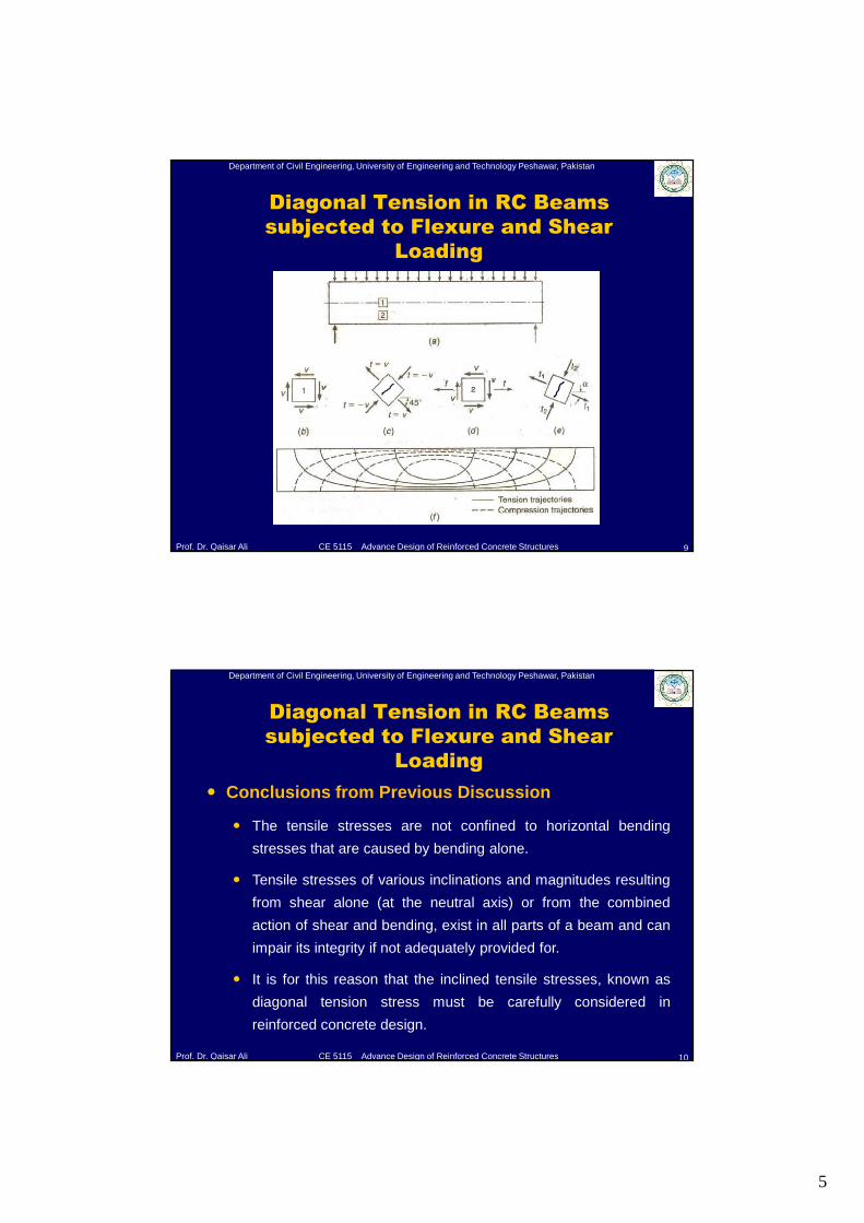
� Conclusions from Previous Discussion
� The tensile stresses are not confined to horizontal bending
stresses that are caused by bending alone.
� Tensile stresses of various inclinations and magnitudes resulting
from shear alone (at the neutral axis) or from the combined
action of shear and bending, exist in all parts of a beam and can
impair its integrity if not adequately provided for.
� It is for this reason that the inclined tensile stresses, known as
diagonal tension stress must be carefully considered in
reinforced concrete design.
6
Department of Civil Engineering, University of Engineering and Technology Peshawar, Pakistan
Prof. Dr. Qaisar Ali CE 5115 Advance Design of Reinforced Concrete Structures
Types of Cracks in Reinforced Concrete
Beam
11
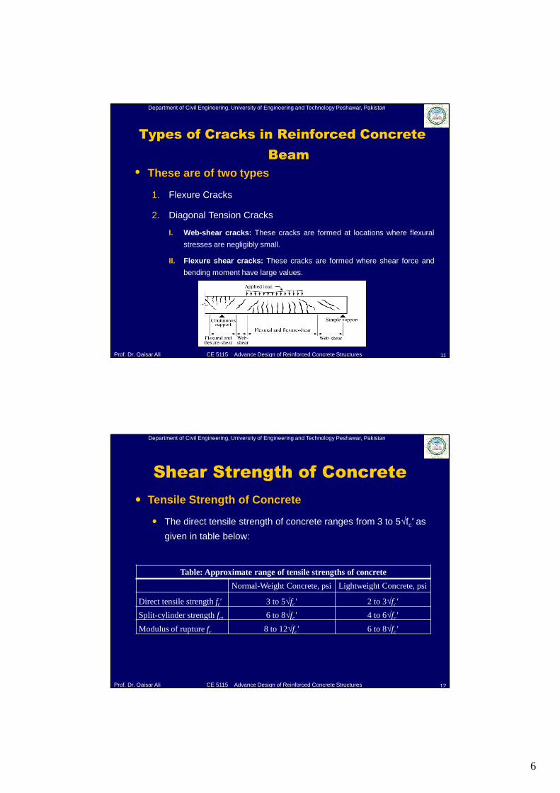
• These are of two types
1. Flexure Cracks
2. Diagonal Tension Cracks
I. Web-shear cracks: These cracks are formed at locations where flexural
stresses are negligibly small.
II. Flexure shear cracks: These cracks are formed where shear force and
bending moment have large values.
Department of Civil Engineering, University of Engineering and Technology Peshawar, Pakistan
Prof. Dr. Qaisar Ali CE 5115 Advance Design of Reinforced Concrete Structures
Shear Strength of Concrete
12
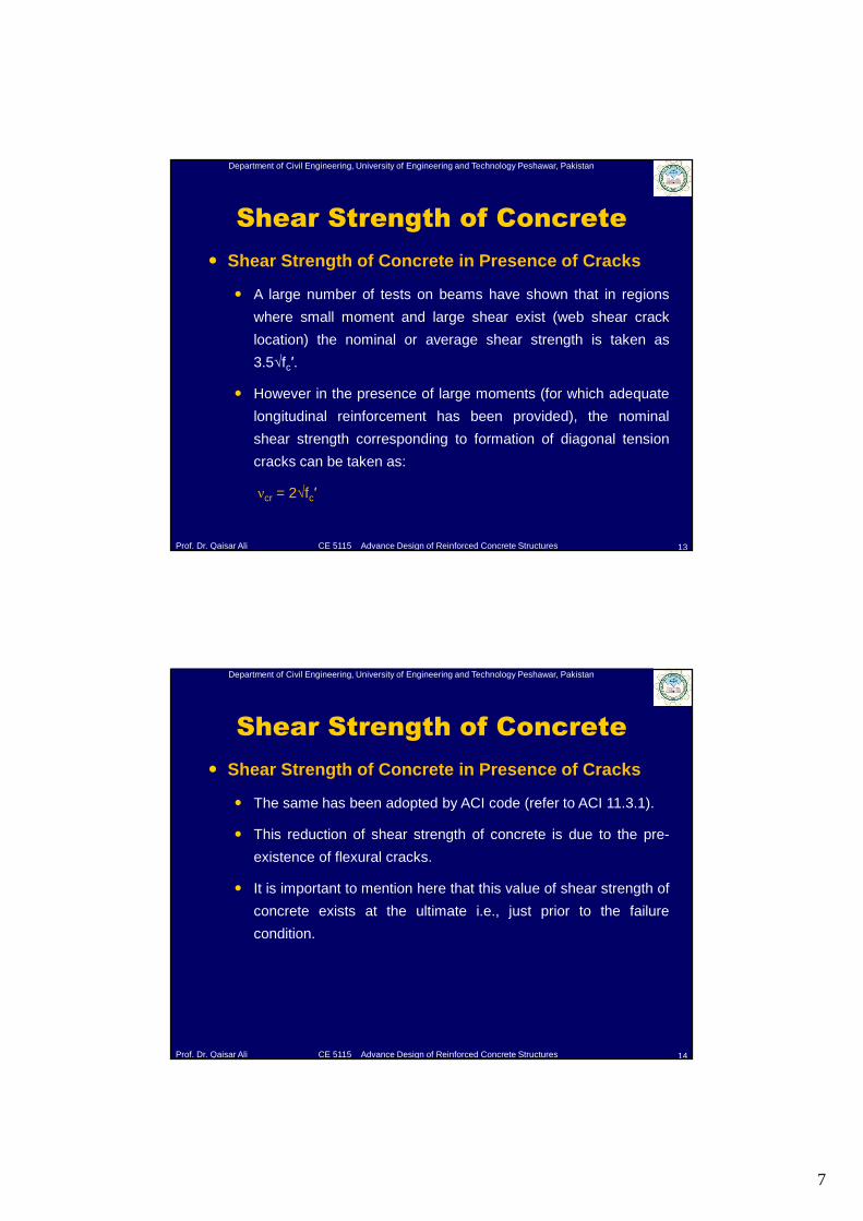
� Tensile Strength of Concrete
� The direct tensile strength of concrete ranges from 3 to 5√fc′ as
given in table below:
Table: Approximate range of tensile strengths of concrete
Normal-Weight Concrete, psi Lightweight Concrete, psi
Direct tensile strength ft' 3 to 5√fc' 2 to 3√fc'
Split-cylinder strength fct 6 to 8√fc' 4 to 6√fc'
Modulus of rupture fr 8 to 12√fc' 6 to 8√fc'
7
Department of Civil Engineering, University of Engineering and Technology Peshawar, Pakistan
Prof. Dr. Qaisar Ali CE 5115 Advance Design of Reinforced Concrete Structures
Shear Strength of Concrete
13
� Shear Strength of Concrete in Presence of Cracks
� A large number of tests on beams have shown that in regions
where small moment and large shear exist (web shear crack
location) the nominal or average shear strength is taken as
3.5√fc′.
� However in the presence of large moments (for which adequate
longitudinal reinforcement has been provided), the nominal
shear strength corresponding to formation of diagonal tension
cracks can be taken as:
νcr = 2√fc′
Department of Civil Engineering, University of Engineering and Technology Peshawar, Pakistan
Prof. Dr. Qaisar Ali CE 5115 Advance Design of Reinforced Concrete Structures
Shear Strength of Concrete
14
� Shear Strength of Concrete in Presence of Cracks
� The same has been adopted by ACI code (refer to ACI 11.3.1).
� This reduction of shear strength of concrete is due to the pre-
existence of flexural cracks.
� It is important to mention here that this value of shear strength of
concrete exists at the ultimate i.e., just prior to the failure
condition.
8
Department of Civil Engineering, University of Engineering and Technology Peshawar, Pakistan
Prof. Dr. Qaisar Ali CE 5115 Advance Design of Reinforced Concrete Structures
Web Reinforcement Requirement in
Reinforced Concrete Beams
15
� Nominal Shear Capacity (Vn) of Reinforced Concrete
Beam
� Now general expression for shear capacity of reinforced
concrete beam is given as:
Vn = Vc + Vs
Where,
Vc = Nominal shear capacity of concrete,
Vs = Nominal shear capacity of shear reinforcement.
Note: in case of flexural capacity Mn = Mc + Ms (Mc = 0, at ultimate load)
Department of Civil Engineering, University of Engineering and Technology Peshawar, Pakistan
Prof. Dr. Qaisar Ali CE 5115 Advance Design of Reinforced Concrete Structures
Web Reinforcement Requirement in
Reinforced Concrete Beams
16
� Nominal Shear Capacity (Vn) of Reinforced Concrete
Beam
� Unlike moment, in expression for shear, the term Vc ≠ 0 because
test evidence have led to the conservative assumption that just
prior to failure of a web-reinforced beam, the sum of the three
internal shear components is equal to the cracking shear Vcr.
9
Department of Civil Engineering, University of Engineering and Technology Peshawar, Pakistan
Prof. Dr. Qaisar Ali CE 5115 Advance Design of Reinforced Concrete Structures
Web Reinforcement Requirement in
Reinforced Concrete Beams
17
� Nominal Shear Capacity (Vn) of Reinforced Concrete
Beam
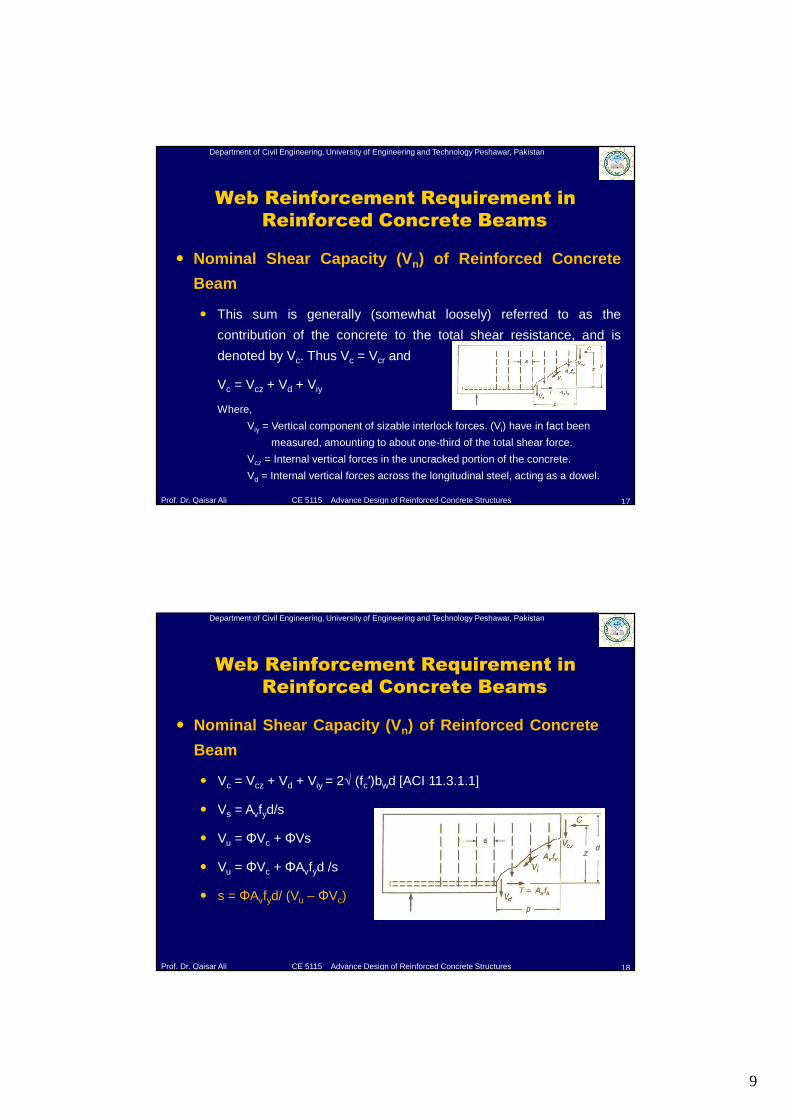
� This sum is generally (somewhat loosely) referred to as the
contribution of the concrete to the total shear resistance, and is
denoted by Vc. Thus Vc = Vcr and
Vc = Vcz + Vd + Viy
Where,
Viy = Vertical component of sizable interlock forces. (Vi) have in fact been
measured, amounting to about one-third of the total shear force.
Vcz = Internal vertical forces in the uncracked portion of the concrete.
Vd = Internal vertical forces across the longitudinal steel, acting as a dowel.
Department of Civil Engineering, University of Engineering and Technology Peshawar, Pakistan
Prof. Dr. Qaisar Ali CE 5115 Advance Design of Reinforced Concrete Structures
� Nominal Shear Capacity (Vn) of Reinforced Concrete
Beam
� Vc = Vcz + Vd + Viy = 2√ (fc′)bwd [ACI 11.3.1.1]
� Vs = Avfyd/s
� Vu = ΦVc + ΦVs
� Vu = ΦVc + ΦAvfyd /s
� s = ΦAvfyd/ (Vu – ΦVc)
Web Reinforcement Requirement in
Reinforced Concrete Beams
18
10
Department of Civil Engineering, University of Engineering and Technology Peshawar, Pakistan
Prof. Dr. Qaisar Ali CE 5115 Advance Design of Reinforced Concrete Structures
ACI Code Provisions for Shear
Design
19
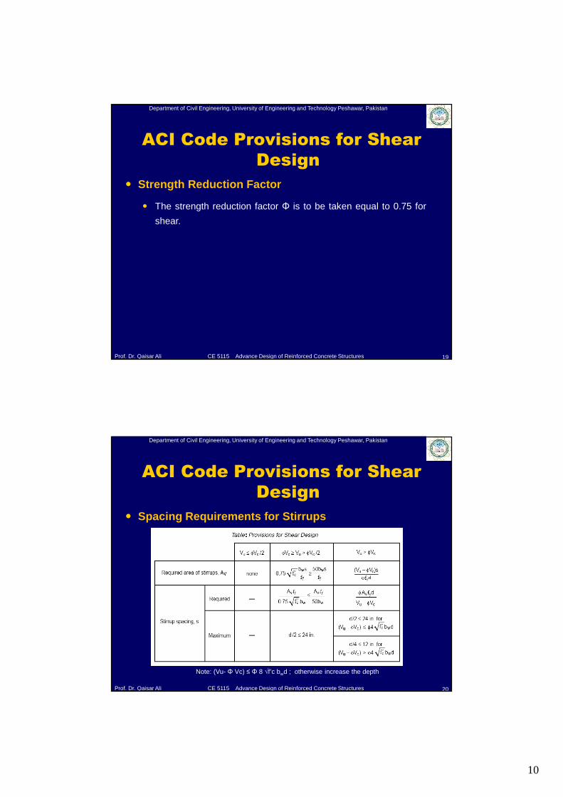
� Strength Reduction Factor
� The strength reduction factor Φ is to be taken equal to 0.75 for
shear.
Department of Civil Engineering, University of Engineering and Technology Peshawar, Pakistan
Prof. Dr. Qaisar Ali CE 5115 Advance Design of Reinforced Concrete Structures
ACI Code Provisions for Shear
Design
20
� Spacing Requirements for Stirrups
Note: (Vu- Φ Vc) ≤ Φ 8 √f’c bwd ; otherwise increase the depth
11
Department of Civil Engineering, University of Engineering and Technology Peshawar, Pakistan
Prof. Dr. Qaisar Ali CE 5115 Advance Design of Reinforced Concrete Structures
ACI Code Provisions for Shear
Design
21
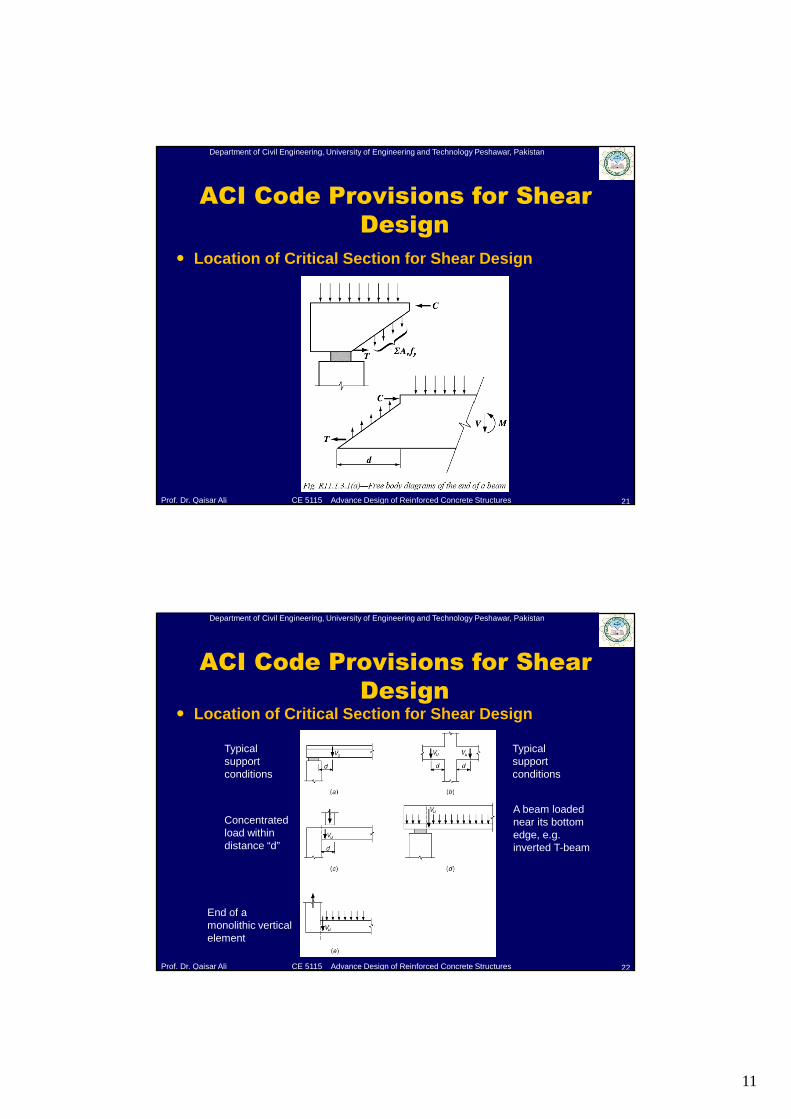
� Location of Critical Section for Shear Design
Department of Civil Engineering, University of Engineering and Technology Peshawar, Pakistan
Prof. Dr. Qaisar Ali CE 5115 Advance Design of Reinforced Concrete Structures
ACI Code Provisions for Shear
Design
22
� Location of Critical Section for Shear Design
Typical support conditions
Typical support conditions
Concentrated load within distance “d”
A beam loaded near its bottom edge, e.g. inverted T-beam
End of a monolithic vertical element
12
Department of Civil Engineering, University of Engineering and Technology Peshawar, Pakistan
Prof. Dr. Qaisar Ali CE 5115 Advance Design of Reinforced Concrete Structures
Effect of Axial Force on Shear
Strength of Concrete Members
23
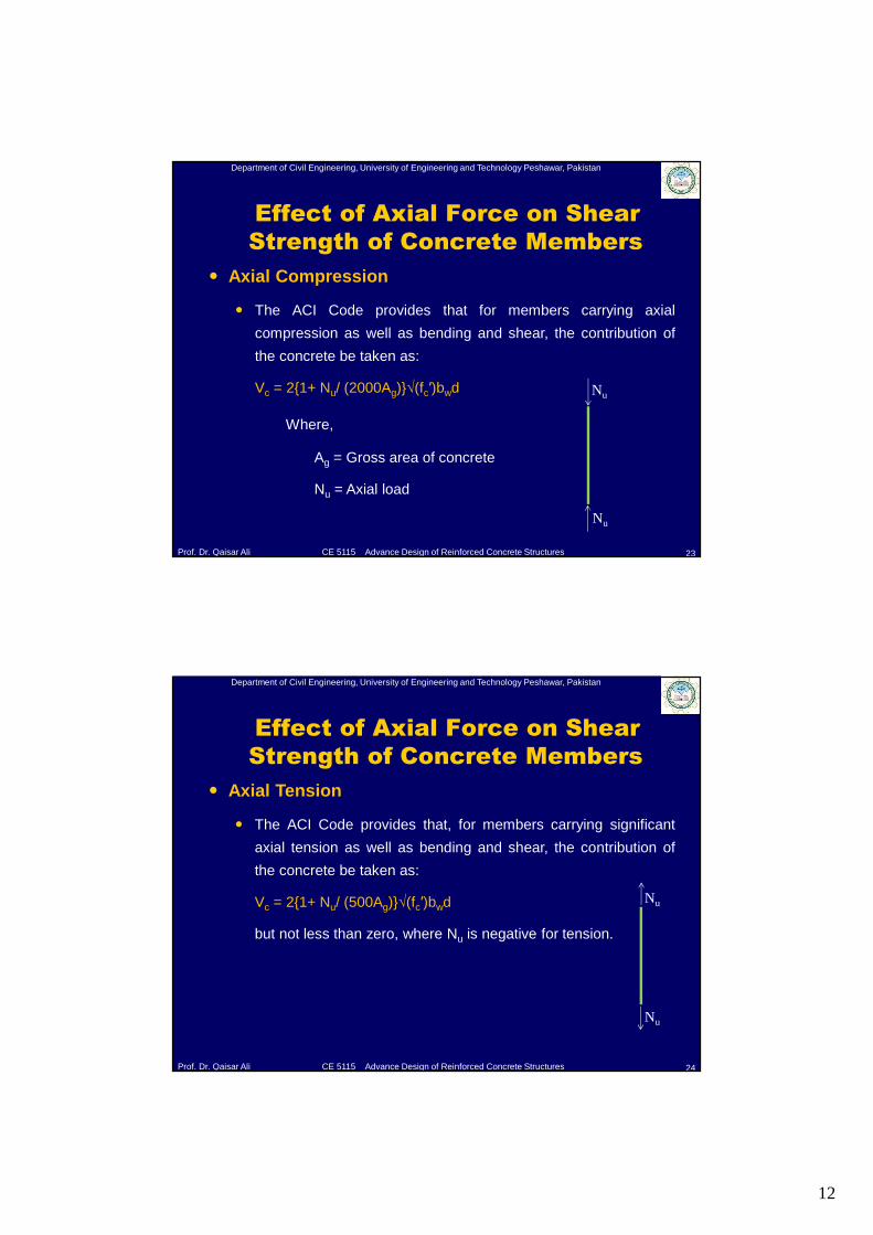
� Axial Compression
� The ACI Code provides that for members carrying axial
compression as well as bending and shear, the contribution of
the concrete be taken as:
Vc = 2{1+ Nu/ (2000Ag)}√(fc′)bwd
Where,
Ag = Gross area of concrete
Nu = Axial load
Nu
Nu
Department of Civil Engineering, University of Engineering and Technology Peshawar, Pakistan
Prof. Dr. Qaisar Ali CE 5115 Advance Design of Reinforced Concrete Structures
Effect of Axial Force on Shear
Strength of Concrete Members
24
� Axial Tension
� The ACI Code provides that, for members carrying significant
axial tension as well as bending and shear, the contribution of
the concrete be taken as:
Vc = 2{1+ Nu/ (500Ag)}√(fc′)bwd
but not less than zero, where Nu is negative for tension.
Nu
Nu
13
Department of Civil Engineering, University of Engineering and Technology Peshawar, Pakistan
Prof. Dr. Qaisar Ali CE 5115 Advance Design of Reinforced Concrete Structures
Design of RC Members for Torsion
25
Department of Civil Engineering, University of Engineering and Technology Peshawar, Pakistan
Prof. Dr. Qaisar Ali CE 5115 Advance Design of Reinforced Concrete Structures
Torsional Stresses
26
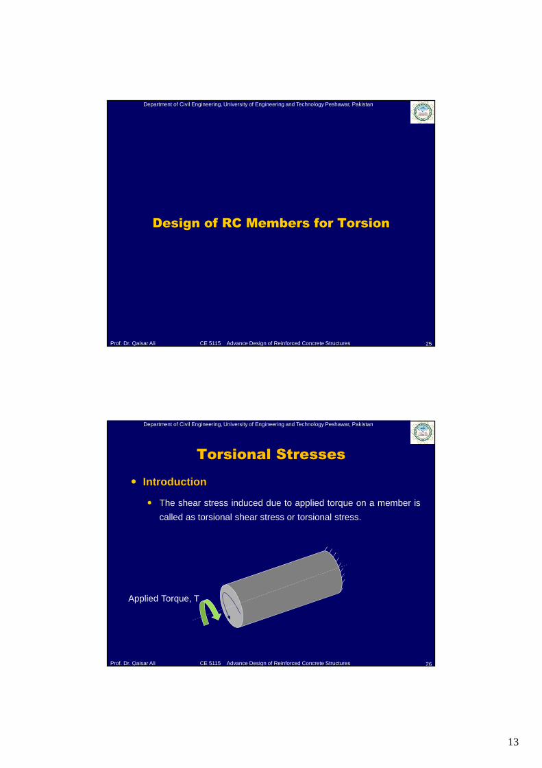
� Introduction
� The shear stress induced due to applied torque on a member is
called as torsional shear stress or torsional stress.
Applied Torque, T
14
Department of Civil Engineering, University of Engineering and Technology Peshawar, Pakistan
Prof. Dr. Qaisar Ali CE 5115 Advance Design of Reinforced Concrete Structures
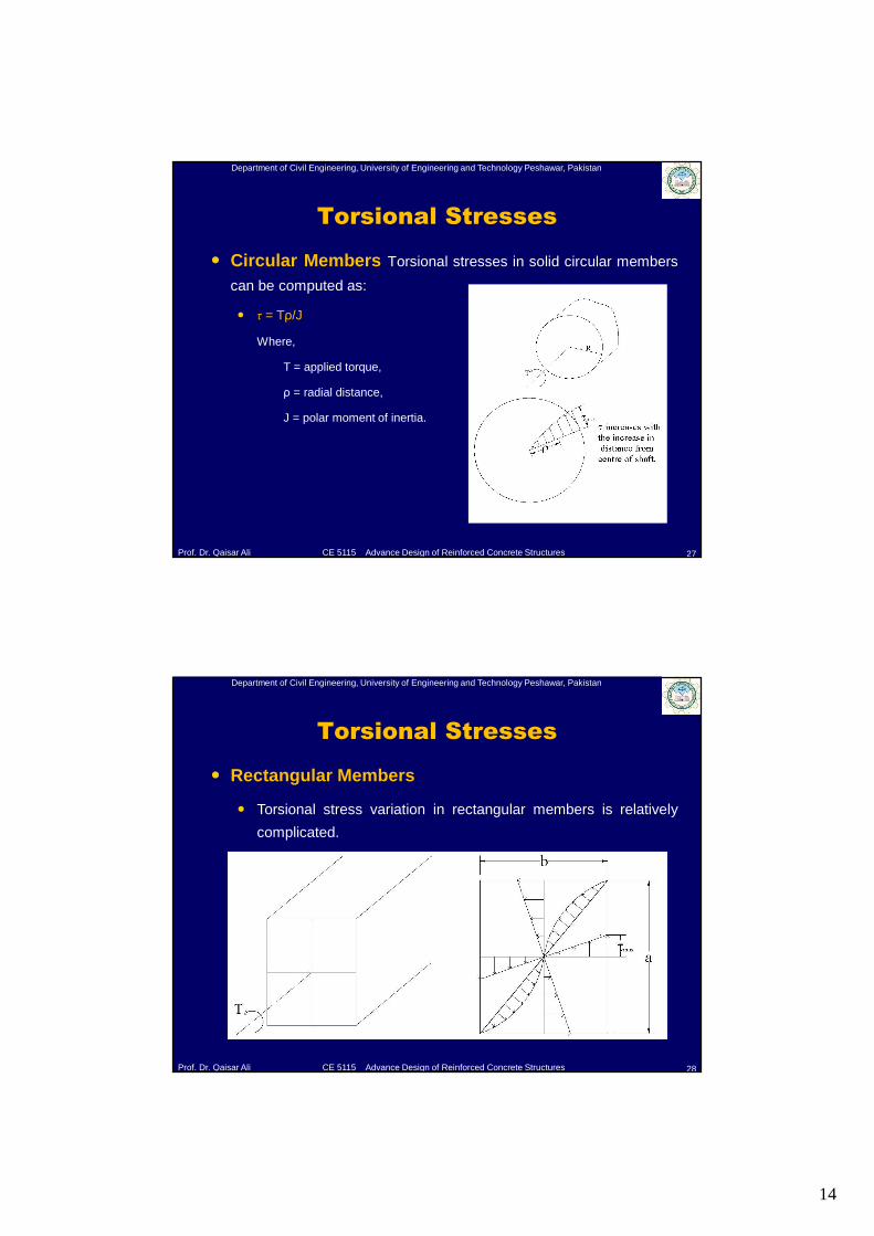
� Circular Members Torsional stresses in solid circular members
can be computed as:
� τ = Tρ/J
Where,
T = applied torque,
ρ = radial distance,
J = polar moment of inertia.
Torsional Stresses
27
Department of Civil Engineering, University of Engineering and Technology Peshawar, Pakistan
Prof. Dr. Qaisar Ali CE 5115 Advance Design of Reinforced Concrete Structures
Torsional Stresses
28
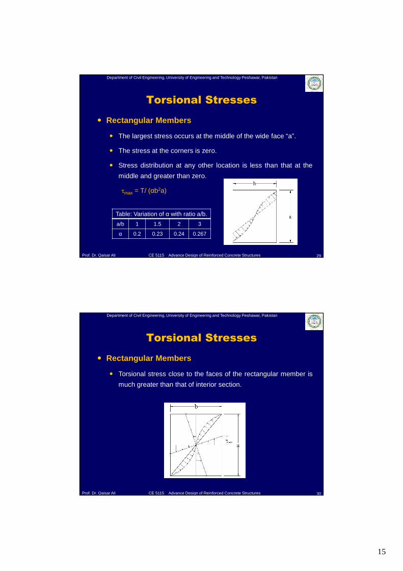
� Rectangular Members
� Torsional stress variation in rectangular members is relatively
complicated.
15
Department of Civil Engineering, University of Engineering and Technology Peshawar, Pakistan
Prof. Dr. Qaisar Ali CE 5115 Advance Design of Reinforced Concrete Structures
Torsional Stresses
29
� Rectangular Members
� The largest stress occurs at the middle of the wide face “a”.
� The stress at the corners is zero.
� Stress distribution at any other location is less than that at the
middle and greater than zero.
τmax = T/ (αb2a)
Table: Variation of α with ratio a/b.
a/b 1 1.5 2 3
α 0.2 0.23 0.24 0.267
Department of Civil Engineering, University of Engineering and Technology Peshawar, Pakistan
Prof. Dr. Qaisar Ali CE 5115 Advance Design of Reinforced Concrete Structures
Torsional Stresses
30
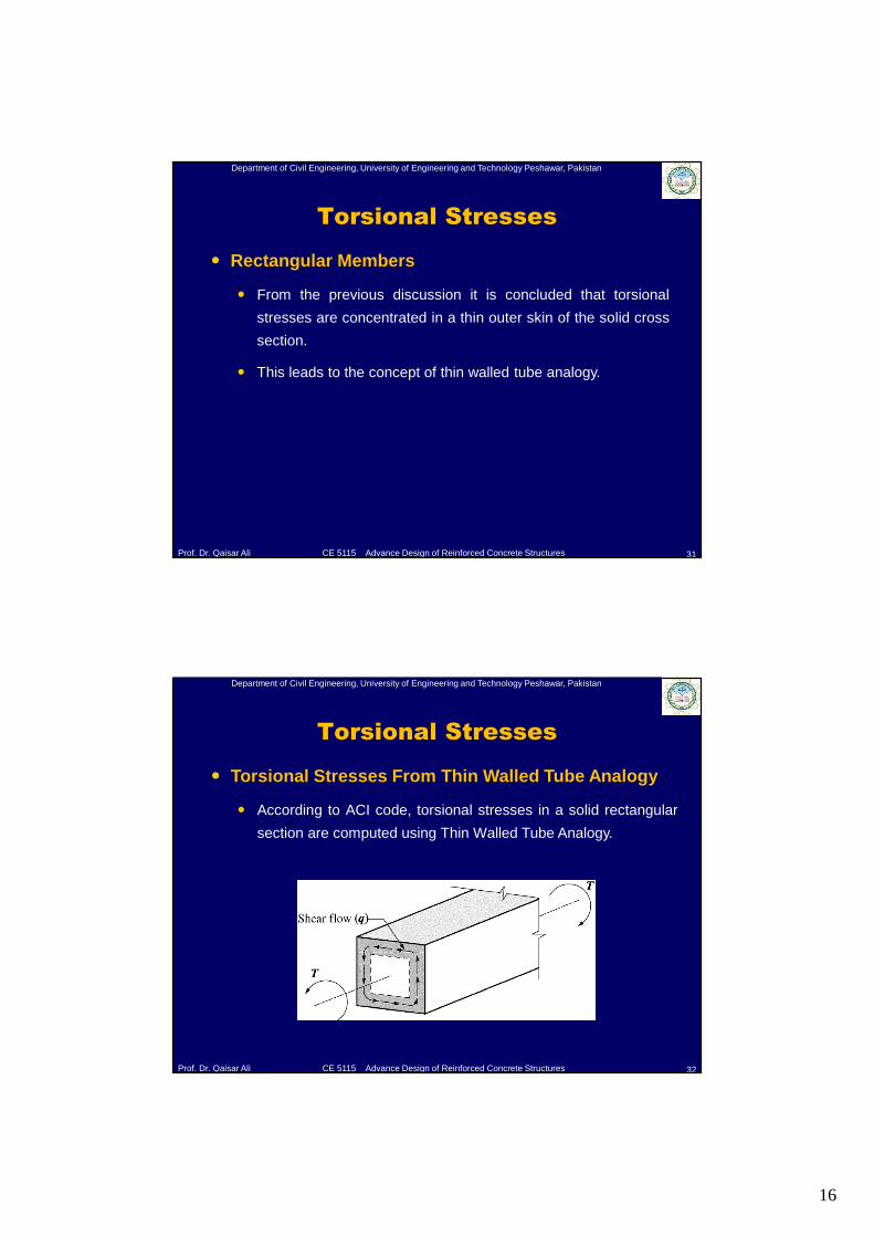
� Rectangular Members
� Torsional stress close to the faces of the rectangular member is
much greater than that of interior section.
16
Department of Civil Engineering, University of Engineering and Technology Peshawar, Pakistan
Prof. Dr. Qaisar Ali CE 5115 Advance Design of Reinforced Concrete Structures
Torsional Stresses
31
� Rectangular Members
� From the previous discussion it is concluded that torsional
stresses are concentrated in a thin outer skin of the solid cross
section.
� This leads to the concept of thin walled tube analogy.
Department of Civil Engineering, University of Engineering and Technology Peshawar, Pakistan
Prof. Dr. Qaisar Ali CE 5115 Advance Design of Reinforced Concrete Structures
Torsional Stresses
32
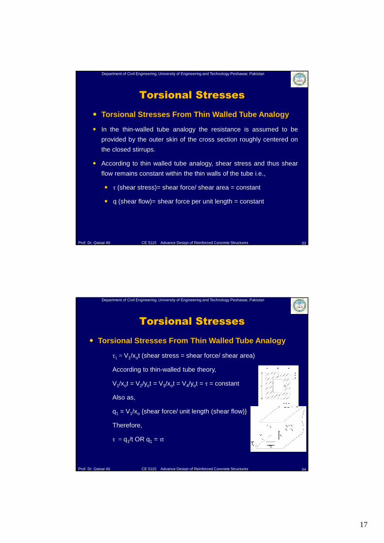
� Torsional Stresses From Thin Walled Tube Analogy
� According to ACI code, torsional stresses in a solid rectangular
section are computed using Thin Walled Tube Analogy.
17
Department of Civil Engineering, University of Engineering and Technology Peshawar, Pakistan
Prof. Dr. Qaisar Ali CE 5115 Advance Design of Reinforced Concrete Structures
Torsional Stresses
33
� Torsional Stresses From Thin Walled Tube Analogy
� In the thin-walled tube analogy the resistance is assumed to be
provided by the outer skin of the cross section roughly centered on
the closed stirrups.
� According to thin walled tube analogy, shear stress and thus shear
flow remains constant within the thin walls of the tube i.e.,
� τ (shear stress)= shear force/ shear area = constant
� q (shear flow)= shear force per unit length = constant
Department of Civil Engineering, University of Engineering and Technology Peshawar, Pakistan
Prof. Dr. Qaisar Ali CE 5115 Advance Design of Reinforced Concrete Structures
Torsional Stresses
34
� Torsional Stresses From Thin Walled Tube Analogy
τ1 = V1/xot (shear stress = shear force/ shear area)
According to thin-walled tube theory,
V1/xot = V2/yot = V3/xot = V4/yot = τ = constant
Also as,
q1 = V1/xo {shear force/ unit length (shear flow)}
Therefore,
τ = q1/t OR q1 = τt
18
Department of Civil Engineering, University of Engineering and Technology Peshawar, Pakistan
Prof. Dr. Qaisar Ali CE 5115 Advance Design of Reinforced Concrete Structures
Torsional Stresses
35
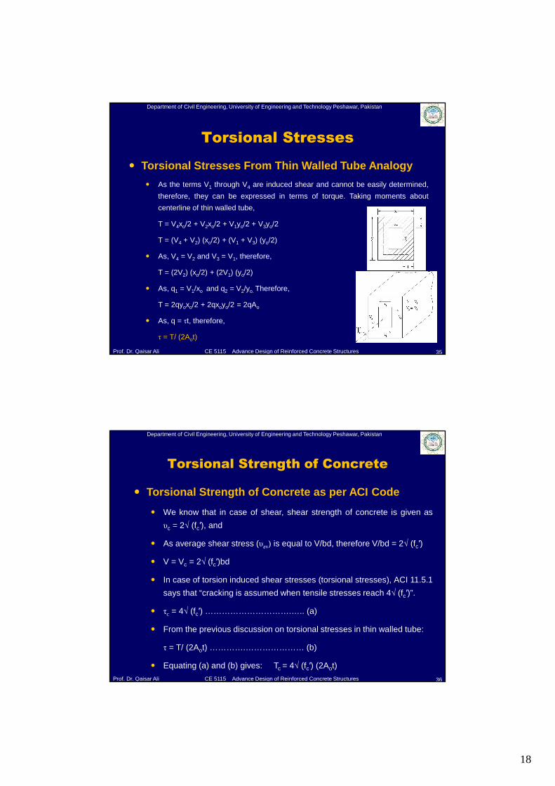
� Torsional Stresses From Thin Walled Tube Analogy
� As the terms V1 through V4 are induced shear and cannot be easily determined,
therefore, they can be expressed in terms of torque. Taking moments about
centerline of thin walled tube,
T = V4xo/2 + V2xo/2 + V1yo/2 + V3yo/2
T = (V4 + V2) (xo/2) + (V1 + V3) (yo/2)
� As, V4 = V2 and V3 = V1, therefore,
T = (2V2) (xo/2) + (2V1) (yo/2)
� As, q1 = V1/xo and q2 = V2/yo. Therefore,
T = 2qyoxo/2 + 2qxoyo/2 = 2qAo
� As, q = τt, therefore,
τ = T/ (2Aot)
Department of Civil Engineering, University of Engineering and Technology Peshawar, Pakistan
Prof. Dr. Qaisar Ali CE 5115 Advance Design of Reinforced Concrete Structures
Torsional Strength of Concrete
36
� Torsional Strength of Concrete as per ACI Code
� We know that in case of shear, shear strength of concrete is given as
υc = 2√ (fc′), and
� As average shear stress (υav) is equal to V/bd, therefore V/bd = 2√ (fc′)
� V = Vc = 2√ (fc′)bd
� In case of torsion induced shear stresses (torsional stresses), ACI 11.5.1
says that “cracking is assumed when tensile stresses reach 4√ (fc′)”.
� τc = 4√ (fc′) ………………………….….. (a)
� From the previous discussion on torsional stresses in thin walled tube:
τ = T/ (2Aot) ………….………………… (b)
� Equating (a) and (b) gives: Tc = 4√ (fc′) (2Aot)
19
Department of Civil Engineering, University of Engineering and Technology Peshawar, Pakistan
Prof. Dr. Qaisar Ali CE 5115 Advance Design of Reinforced Concrete Structures
Torsional Strength of Concrete
37
� Torsional Strength of Concrete as per ACI Code
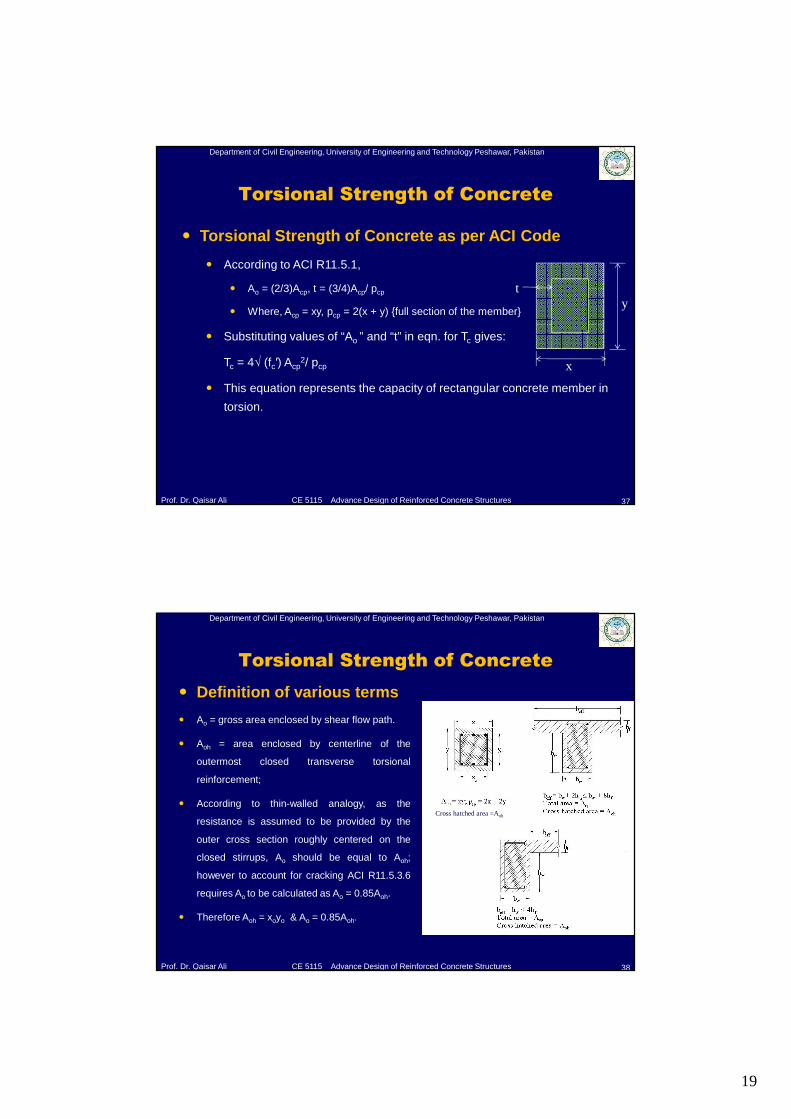
� According to ACI R11.5.1,
� Ao = (2/3)Acp, t = (3/4)Acp/ pcp
� Where, Acp = xy, pcp = 2(x + y) {full section of the member}
� Substituting values of “Ao ” and “t” in eqn. for Tc gives:
Tc = 4√ (fc′) Acp2/ pcp
� This equation represents the capacity of rectangular concrete member in
torsion.
x
yt
Department of Civil Engineering, University of Engineering and Technology Peshawar, Pakistan
Prof. Dr. Qaisar Ali CE 5115 Advance Design of Reinforced Concrete Structures
Torsional Strength of Concrete
38
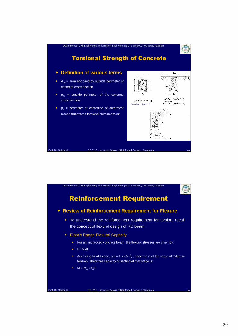
� Definition of various terms
� Ao = gross area enclosed by shear flow path.
� Aoh = area enclosed by centerline of the
outermost closed transverse torsional
reinforcement;
� According to thin-walled analogy, as the
resistance is assumed to be provided by the
outer cross section roughly centered on the
closed stirrups, Ao should be equal to Aoh;
however to account for cracking ACI R11.5.3.6
requires Ao to be calculated as Ao = 0.85Aoh.
� Therefore Aoh = xoyo & Ao = 0.85Aoh.
Cross hatched area =Aoh
20
Department of Civil Engineering, University of Engineering and Technology Peshawar, Pakistan
Prof. Dr. Qaisar Ali CE 5115 Advance Design of Reinforced Concrete Structures
Torsional Strength of Concrete
39
� Definition of various terms
� Acp = area enclosed by outside perimeter of
concrete cross section
� pcp = outside perimeter of the concrete
cross section
� ph = perimeter of centerline of outermost
closed transverse torsional reinforcement
Cross hatched area =Aoh
Department of Civil Engineering, University of Engineering and Technology Peshawar, Pakistan
Prof. Dr. Qaisar Ali CE 5115 Advance Design of Reinforced Concrete Structures
Reinforcement Requirement
40
� Review of Reinforcement Requirement for Flexure
� To understand the reinforcement requirement for torsion, recall
the concept of flexural design of RC beam.
� Elastic Range Flexural Capacity
� For an uncracked concrete beam, the flexural stresses are given by:
� f = My/I
� According to ACI code, at f = fr =7.5 √fc′, concrete is at the verge of failure in
tension. Therefore capacity of section at that stage is:
� M = Mcr = fry/I
21
Department of Civil Engineering, University of Engineering and Technology Peshawar, Pakistan
Prof. Dr. Qaisar Ali CE 5115 Advance Design of Reinforced Concrete Structures
Reinforcement Requirement
41
� Review of Reinforcement Requirement for Flexure
� Ultimate Flexural Capacity
� For a cracked RC beam at ultimate stage, the flexural capacity is given as:
� Mn = Mc + Ms
� Where,
� Mc = Nominal flexural capacity of concrete in tension,
� Ms = Nominal flexural capacity of tension steel.
Department of Civil Engineering, University of Engineering and Technology Peshawar, Pakistan
Prof. Dr. Qaisar Ali CE 5115 Advance Design of Reinforced Concrete Structures
Reinforcement Requirement
42
� Review of Reinforcement Requirement for Flexure
� Ultimate Flexural Capacity
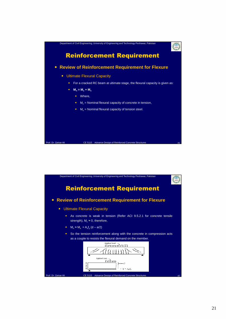
� As concrete is weak in tension (Refer ACI 9.5.2.1 for concrete tensile
strength), Mc ≈ 0, therefore,
� Mn ≈ Ms = Asfy (d – a/2)
� So the tension reinforcement along with the concrete in compression acts
as a couple to resists the flexural demand on the member.
22
Department of Civil Engineering, University of Engineering and Technology Peshawar, Pakistan
Prof. Dr. Qaisar Ali CE 5115 Advance Design of Reinforced Concrete Structures
Reinforcement Requirement
43
� Review of Reinforcement Requirement for Shear
� Similarly, recall the concept of shear design of RC beam.
� Elastic Range Shear Capacity
� For an uncracked concrete beam, the shear stresses are given by:
� υ = VQ/Ib
� According to ACI code, υ = υcr = 2√fc′ is the nominal shear strength
corresponding to formation of diagonal tension cracks. Therefore shear
capacity of section at that stage is:
� Vcr= υcr Ib/Q = 2√fc′ Ib/Q
Department of Civil Engineering, University of Engineering and Technology Peshawar, Pakistan
Prof. Dr. Qaisar Ali CE 5115 Advance Design of Reinforced Concrete Structures
Reinforcement Requirement
44
� Review of Reinforcement Requirement for Shear
� Ultimate Shear Capacity
� For a cracked RC beam at ultimate stage, the shear capacity is given as:
� Vn = Vc + Vs
� Where,
� Vc = Nominal shear capacity of concrete,
� Vs = Nominal shear capacity of shear reinforcement.
23
Department of Civil Engineering, University of Engineering and Technology Peshawar, Pakistan
Prof. Dr. Qaisar Ali CE 5115 Advance Design of Reinforced Concrete Structures
Reinforcement Requirement
45
� Review of Reinforcement Requirement for Shear
� Ultimate Shear Capacity
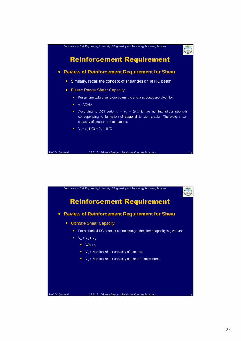
� Unlike flexure, the term Vc ≠ 0 because from test evidence:
� Vc = Vcz + Vd + Viy = 2√ (fc′)bwd [ACI 11.3.1.1]
� Therefore shear steel (stirrups) along with the contribution of concrete (Vc)
acts together to resists the shear demand due to applied load on the
member.
Department of Civil Engineering, University of Engineering and Technology Peshawar, Pakistan
Prof. Dr. Qaisar Ali CE 5115 Advance Design of Reinforced Concrete Structures
Reinforcement Requirement
46
� Reinforcement requirement for Torsion
� In the case of Torsion
� ΦTn= ΦTc+ ΦTs
� ACI Code requires that ΦTc shall be taken equal to zero.
� Therfore ΦTn= ΦTs
� We will see in the next slides that how ΦTs is calculated.
24
Department of Civil Engineering, University of Engineering and Technology Peshawar, Pakistan
Prof. Dr. Qaisar Ali CE 5115 Advance Design of Reinforced Concrete Structures
Reinforcement Requirement
47
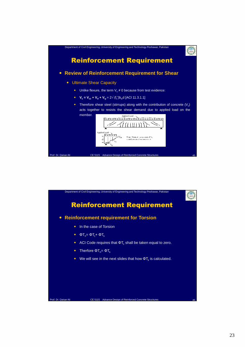
� Reinforcement requirement for Torsion
� Reinforcement requirement for reinforced concrete members
subjected to torsion is determined using thin walled tube and
space truss analogies.
As discussed earlier, from
thin walled tube analogy,
internal effects in the form of
induced shear forces (V1 to
V4) will generate due to
applied torque (T) as
shown.
Department of Civil Engineering, University of Engineering and Technology Peshawar, Pakistan
Prof. Dr. Qaisar Ali CE 5115 Advance Design of Reinforced Concrete Structures
Reinforcement Requirement
48
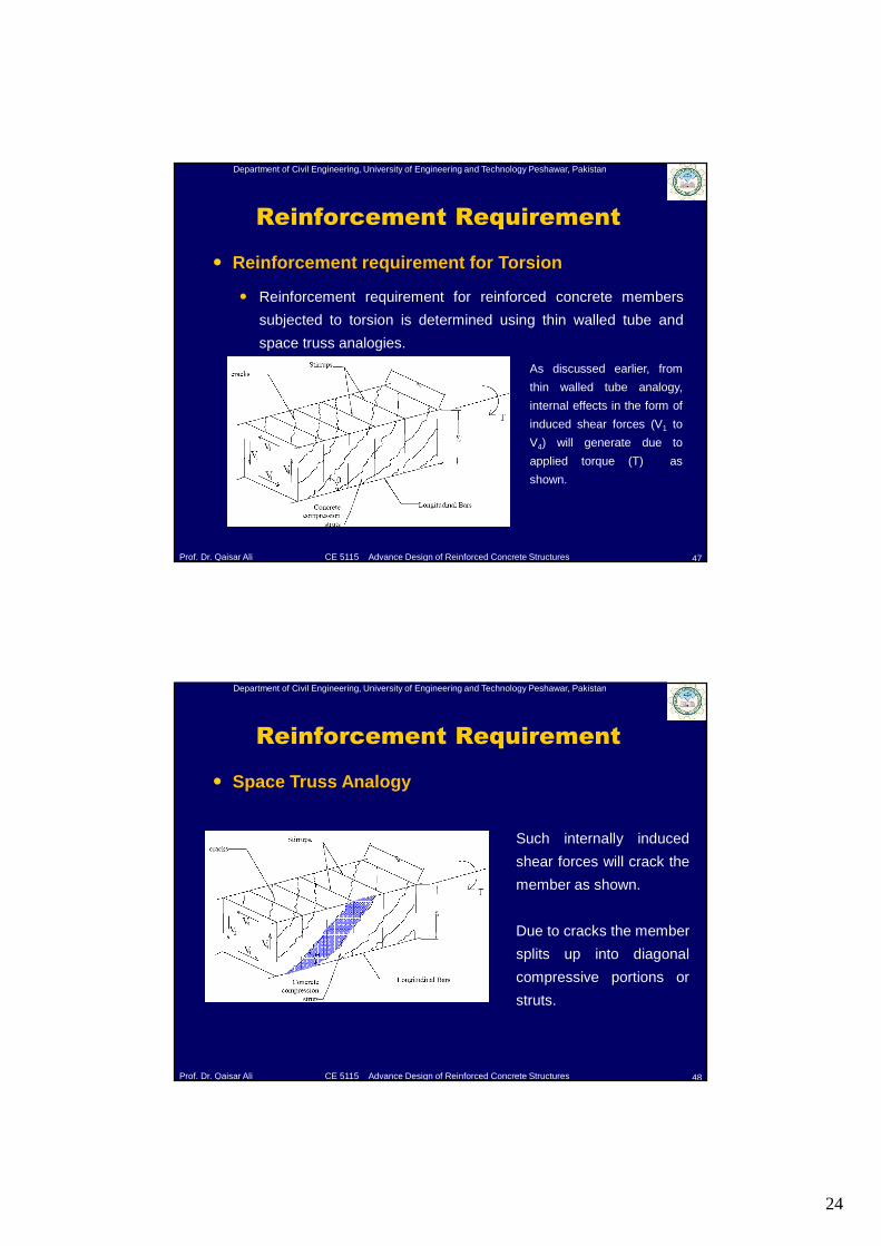
� Space Truss Analogy
Such internally induced
shear forces will crack the
member as shown.
Due to cracks the member
splits up into diagonal
compressive portions or
struts.
25
Department of Civil Engineering, University of Engineering and Technology Peshawar, Pakistan
Prof. Dr. Qaisar Ali CE 5115 Advance Design of Reinforced Concrete Structures
Reinforcement Requirement
49
� Space Truss Analogy
C
CHCV
If the compressive force in the strut is
C, then it can be resolved into two
components:
CH = Horizontal component
CV = Vertical component
Longitudinal reinforcement shall be
provided to resist CH and vertical
stirrups shall be provided to resist CV.
This leads to space truss analogy.
Department of Civil Engineering, University of Engineering and Technology Peshawar, Pakistan
Prof. Dr. Qaisar Ali CE 5115 Advance Design of Reinforced Concrete Structures
Reinforcement Requirement
50
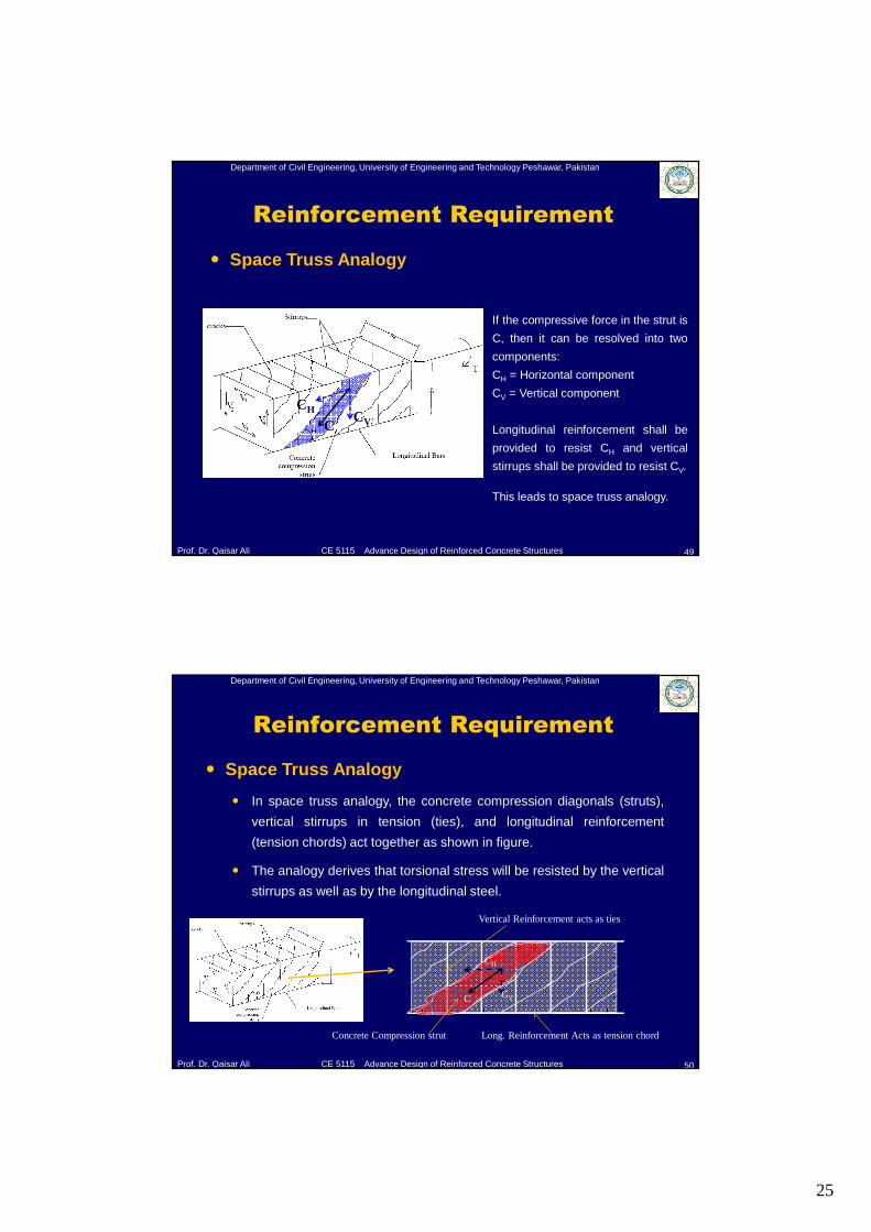
� Space Truss Analogy
� In space truss analogy, the concrete compression diagonals (struts),
vertical stirrups in tension (ties), and longitudinal reinforcement
(tension chords) act together as shown in figure.
� The analogy derives that torsional stress will be resisted by the vertical
stirrups as well as by the longitudinal steel.
Vertical Reinforcement acts as ties
Long. Reinforcement Acts as tension chordConcrete Compression strut
C
CH
CV
26
Department of Civil Engineering, University of Engineering and Technology Peshawar, Pakistan
Prof. Dr. Qaisar Ali CE 5115 Advance Design of Reinforced Concrete Structures
Reinforcement Requirement
51
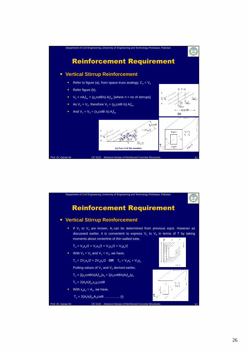
� Vertical Stirrup Reinforcement
� Refer to figure (a), from space truss analogy, Cv = V4
� Refer figure (b),
� V4 = nAtfyv = (yocotθ/s) Atfyv [where n = no of stirrups]
� As V4 = V2, therefore V2 = (yocotθ /s) Atfyv
� And V1 = V3 = (xocotθ /s) Atfyv (b)
(a) Face 4 of the member.
C CV
CH
∆N4
V4
Department of Civil Engineering, University of Engineering and Technology Peshawar, Pakistan
Prof. Dr. Qaisar Ali CE 5115 Advance Design of Reinforced Concrete Structures
� Vertical Stirrup Reinforcement
� If V1 to V4 are known, At can be determined from previous eqns. However as
discussed earlier, it is convenient to express V1 to V4 in terms of T by taking
moments about centerline of thin walled tube,
Tn = V4xo/2 + V2xo/2 + V1yo/2 + V3yo/2
� With V4 = V2 and V1 = V3, we have,
Tn = 2V2xo/2 + 2V1yo/2 OR Tn = V2xo + V1yo
Putting values of V1 and V2 derived earlier,
Tn = {(yocotθ/s)Atfyv}xo + {(xocotθ/s)Atfyv}yo
Tn = 2(At/s)fyvxoyocotθ
� With xoyo = Ao, we have,
Tn = 2(At/s)fyvAocotθ ………….. (i)
Reinforcement Requirement
52
27
Department of Civil Engineering, University of Engineering and Technology Peshawar, Pakistan
Prof. Dr. Qaisar Ali CE 5115 Advance Design of Reinforced Concrete Structures
Reinforcement Requirement
53
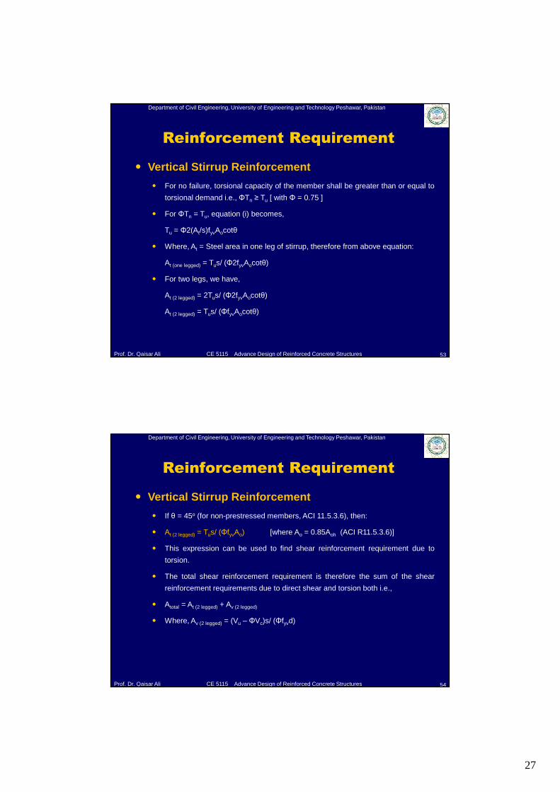
� Vertical Stirrup Reinforcement
� For no failure, torsional capacity of the member shall be greater than or equal to
torsional demand i.e., ΦTn ≥ Tu [ with Φ = 0.75 ]
� For ΦTn = Tu, equation (i) becomes,
Tu = Φ2(At/s)fyvAocotθ
� Where, At = Steel area in one leg of stirrup, therefore from above equation:
At (one legged) = Tus/ (Φ2fyvAocotθ)
� For two legs, we have,
At (2 legged) = 2Tus/ (Φ2fyvAocotθ)
At (2 legged) = Tus/ (ΦfyvAocotθ)
Department of Civil Engineering, University of Engineering and Technology Peshawar, Pakistan
Prof. Dr. Qaisar Ali CE 5115 Advance Design of Reinforced Concrete Structures
Reinforcement Requirement
54
� Vertical Stirrup Reinforcement
� If θ = 45o (for non-prestressed members, ACI 11.5.3.6), then:
� At (2 legged) = Tus/ (ΦfyvAo) [where Ao = 0.85Aoh (ACI R11.5.3.6)]
� This expression can be used to find shear reinforcement requirement due to
torsion.
� The total shear reinforcement requirement is therefore the sum of the shear
reinforcement requirements due to direct shear and torsion both i.e.,
� Atotal = At (2 legged) + Av (2 legged)
� Where, Av (2 legged) = (Vu – ΦVc)s/ (Φfyvd)
28
Department of Civil Engineering, University of Engineering and Technology Peshawar, Pakistan
Prof. Dr. Qaisar Ali CE 5115 Advance Design of Reinforced Concrete Structures
Reinforcement Requirement
55
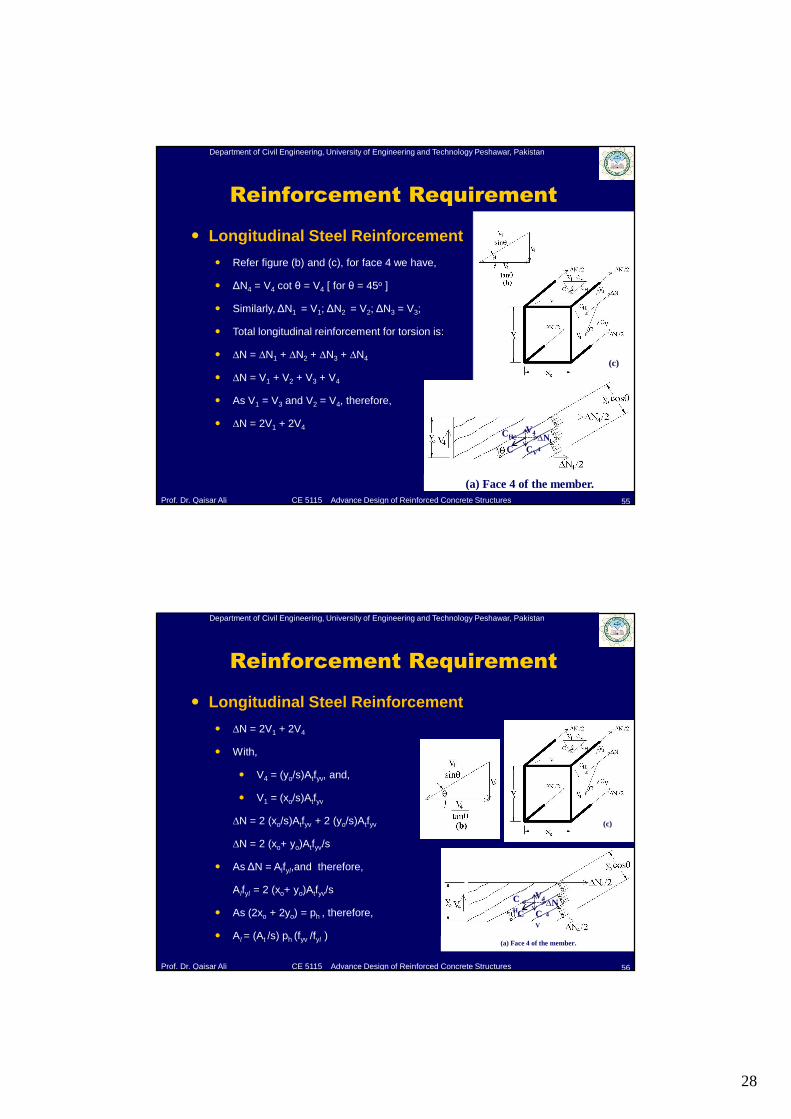
� Longitudinal Steel Reinforcement
� Refer figure (b) and (c), for face 4 we have,
� ΔN4 = V4 cot θ = V4 [ for θ = 45o ]
� Similarly, ΔN1 = V1; ΔN2 = V2; ΔN3 = V3;
� Total longitudinal reinforcement for torsion is:
� ∆N = ∆N1 + ∆N2 + ∆N3 + ∆N4
� ∆N = V1 + V2 + V3 + V4
� As V1 = V3 and V2 = V4, therefore,
� ∆N = 2V1 + 2V4
(c)
(a) Face 4 of the member.
C CV
CH ∆N4
V4
Department of Civil Engineering, University of Engineering and Technology Peshawar, Pakistan
Prof. Dr. Qaisar Ali CE 5115 Advance Design of Reinforced Concrete Structures
Reinforcement Requirement
56
� Longitudinal Steel Reinforcement
� ∆N = 2V1 + 2V4
� With,
� V4 = (yo/s)Atfyv, and,
� V1 = (xo/s)Atfyv
∆N = 2 (xo/s)Atfyv + 2 (yo/s)Atfyv
∆N = 2 (xo+ yo)Atfyv/s
� As ΔN = Alfyl,and therefore,
Alfyl = 2 (xo+ yo)Atfyv/s
� As (2xo + 2yo) = ph , therefore,
� Al = (At /s) ph (fyv /fyl )
(c)
(a) Face 4 of the member.
C CV
CH
∆N4
V4
29
Department of Civil Engineering, University of Engineering and Technology Peshawar, Pakistan
Prof. Dr. Qaisar Ali CE 5115 Advance Design of Reinforced Concrete Structures
Reinforcement Requirement
57
� Longitudinal Steel Reinforcement
� Now as derived earlier,
At (one legged) = Tus/ (Φ2fyvAo)
� Therefore expression for Al becomes,
Al = {(Tus/ (Φ2fyvAo) /s} ph (fyv /fyl )
Al = Tu ph / (Φ2fylAo)
� This expression can be used to find the longitudinal reinforcement requirement
due to torsion.
Department of Civil Engineering, University of Engineering and Technology Peshawar, Pakistan
Prof. Dr. Qaisar Ali CE 5115 Advance Design of Reinforced Concrete Structures
ACI Requirements
58
� Concrete Part in Torsional Capacity of RC Member
� According to ACI R11.5.3.5, in the calculation of Tn, all the
torque is assumed to be resisted by stirrups and longitudinal
steel with Tc = 0. At the same time, the shear resisted by
concrete Vc is assumed to be unchanged by the presence of
torsion.
30
Department of Civil Engineering, University of Engineering and Technology Peshawar, Pakistan
Prof. Dr. Qaisar Ali CE 5115 Advance Design of Reinforced Concrete Structures
ACI Requirements
59
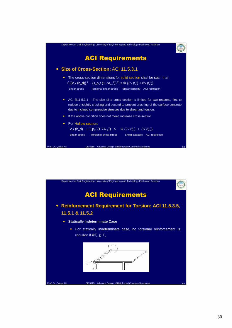
� Size of Cross-Section: ACI 11.5.3.1
� The cross-section dimensions for solid section shall be such that:
√ [{Vu/ (bwd)} 2 + {Tuph/ (1.7Aoh2)} 2] ≤ Φ {2√ (fc′) + 8√ (fc′)}
Shear stress Torsional shear stress Shear capacity ACI restriction
� ACI R11.5.3.1 —The size of a cross section is limited for two reasons, first to
reduce unsightly cracking and second to prevent crushing of the surface concrete
due to inclined compressive stresses due to shear and torsion.
� If the above condition does not meet, increase cross-section.
� For Hollow section:
Vu/ (bwd) + Tuph/ (1.7Aoh2) ≤ Φ {2√ (fc′) + 8√ (fc′)}
Shear stress Torsional shear stress Shear capacity ACI restriction
Department of Civil Engineering, University of Engineering and Technology Peshawar, Pakistan
Prof. Dr. Qaisar Ali CE 5115 Advance Design of Reinforced Concrete Structures
ACI Requirements
60
� Reinforcement Requirement for Torsion: ACI 11.5.3.5,
11.5.1 & 11.5.2
� Statically Indeterminate Case
� For statically indeterminate case, no torsional reinforcement is
required if ΦTc ≥ Tu
31
Department of Civil Engineering, University of Engineering and Technology Peshawar, Pakistan
Prof. Dr. Qaisar Ali CE 5115 Advance Design of Reinforced Concrete Structures
ACI Requirements
61
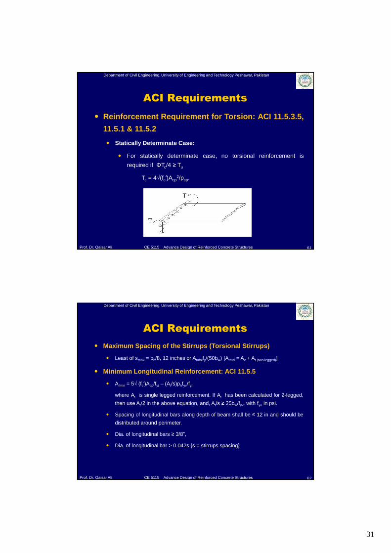
� Reinforcement Requirement for Torsion: ACI 11.5.3.5,
11.5.1 & 11.5.2
� Statically Determinate Case:
� For statically determinate case, no torsional reinforcement is
required if ΦTc/4 ≥ Tu
Tc = 4√(fc′)Acp2/pcp.
Department of Civil Engineering, University of Engineering and Technology Peshawar, Pakistan
Prof. Dr. Qaisar Ali CE 5115 Advance Design of Reinforced Concrete Structures
ACI Requirements
62
� Maximum Spacing of the Stirrups (Torsional Stirrups)
� Least of smax = ph/8, 12 inches or Atotalfy/(50bw) [Atotal = Av + At (two legged)]
� Minimum Longitudinal Reinforcement: ACI 11.5.5
� Almin = 5√ (fc′)Acp/fyl – (At/s)phfyv/fyl
where At is single legged reinforcement. If At has been calculated for 2-legged,
then use At/2 in the above equation, and, At/s ≥ 25bw/fyv, with fyv in psi.
� Spacing of longitudinal bars along depth of beam shall be ≤ 12 in and should be
distributed around perimeter.
� Dia. of longitudinal bars ≥ 3/8″,
� Dia. of longitudinal bar > 0.042s {s = stirrups spacing}
32
Department of Civil Engineering, University of Engineering and Technology Peshawar, Pakistan
Prof. Dr. Qaisar Ali CE 5115 Advance Design of Reinforced Concrete Structures
Steps for Design of Reinforced Concrete
Members Subjected to Torsion
63
� Determine ΦTcr , if ΦTcr/4 < Tu for statically determinate case or ΦTcr < Tu for
indeterminate case, torsional reinforcement is required.
� Check dimensions according to 11.5.3.1.
� Calculate At (2 legged) = Tus/ (ΦfyvAo) {where Ao = 0.85Aoh) and Av (2 legged) = (Vu – ΦVc)s/
(Φfyd)
� Atotal = At + Av. Then determine spacing.
� Check spacing with maximum spacing requirements of ACI.
� Al = Tuph/ (Φ2Aofyl)
� Check maximum spacing, minimum reinforcement and diameter of longitudinal bars.
Department of Civil Engineering, University of Engineering and Technology Peshawar, Pakistan
Prof. Dr. Qaisar Ali CE 5115 Advance Design of Reinforced Concrete Structures
Example
64
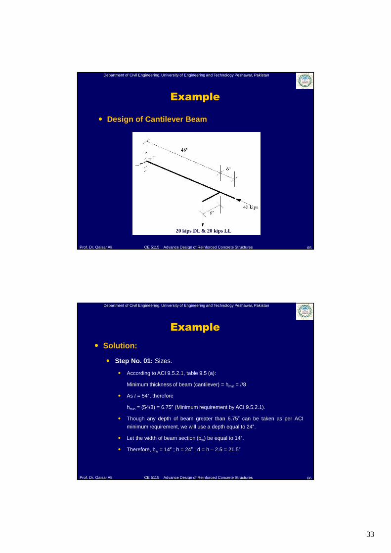
� Design of Cantilever Beam:
� A cantilever beam supports its own dead load plus a
concentrated load. The beam is 54 inches long, and the
concentrated load acts at a point 6 inches from the end of the
beam and 6 inches away from the centroidal axis of the member.
� The un-factored concentrated load consists of a 20-kip dead and
20 kip live load. The beam also supports an un-factored axial
compressive dead load of 40 kip.
� Use normal weight concrete with fc′ = 3000 psi and both fy and fyt
= 60000 psi.
33
Department of Civil Engineering, University of Engineering and Technology Peshawar, Pakistan
Prof. Dr. Qaisar Ali CE 5115 Advance Design of Reinforced Concrete Structures
Example
65
20 kips DL & 20 kips LL
� Design of Cantilever Beam
Department of Civil Engineering, University of Engineering and Technology Peshawar, Pakistan
Prof. Dr. Qaisar Ali CE 5115 Advance Design of Reinforced Concrete Structures
Example
66
� Solution:
� Step No. 01: Sizes.
� According to ACI 9.5.2.1, table 9.5 (a):
Minimum thickness of beam (cantilever) = hmin = l/8
� As l = 54″, therefore
hmin = (54/8) = 6.75″ (Minimum requirement by ACI 9.5.2.1).
� Though any depth of beam greater than 6.75″ can be taken as per ACI
minimum requirement, we will use a depth equal to 24″.
� Let the width of beam section (bw) be equal to 14″.
� Therefore, bw = 14″ ; h = 24″ ; d = h – 2.5 = 21.5″
34
Department of Civil Engineering, University of Engineering and Technology Peshawar, Pakistan
Prof. Dr. Qaisar Ali CE 5115 Advance Design of Reinforced Concrete Structures
Example
67
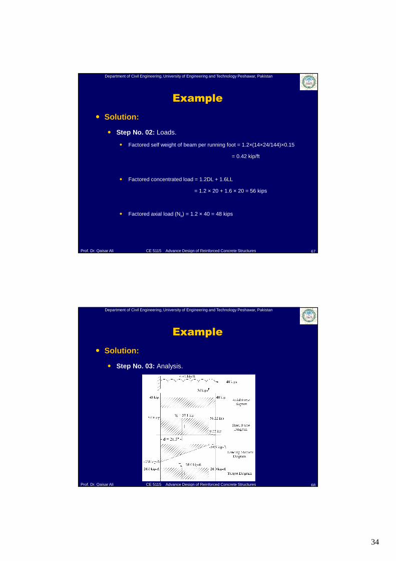
� Solution:
� Step No. 02: Loads.
� Factored self weight of beam per running foot = 1.2×(14×24/144)×0.15
= 0.42 kip/ft
� Factored concentrated load = 1.2DL + 1.6LL
= 1.2 × 20 + 1.6 × 20 = 56 kips
� Factored axial load (Nu) = 1.2 × 40 = 48 kips
Department of Civil Engineering, University of Engineering and Technology Peshawar, Pakistan
Prof. Dr. Qaisar Ali CE 5115 Advance Design of Reinforced Concrete Structures
Example
68
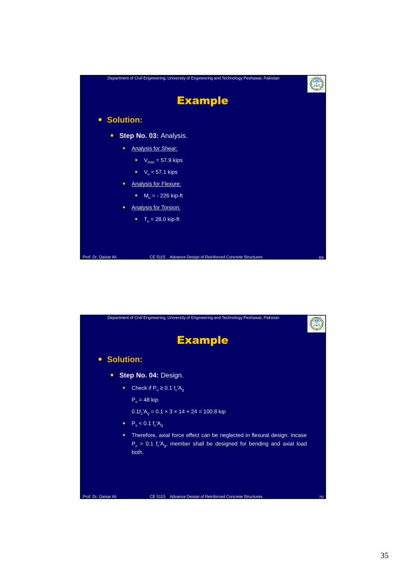
� Solution:
� Step No. 03: Analysis.
35
Department of Civil Engineering, University of Engineering and Technology Peshawar, Pakistan
Prof. Dr. Qaisar Ali CE 5115 Advance Design of Reinforced Concrete Structures
Example
69
� Solution:
� Step No. 03: Analysis.
� Analysis for Shear:
� Vmax = 57.9 kips
� Vu = 57.1 kips
� Analysis for Flexure:
� Mu = - 226 kip-ft
� Analysis for Torsion:
� Tu = 28.0 kip-ft
Department of Civil Engineering, University of Engineering and Technology Peshawar, Pakistan
Prof. Dr. Qaisar Ali CE 5115 Advance Design of Reinforced Concrete Structures
Example
70
� Solution:
� Step No. 04: Design.
� Check if Pu ≥ 0.1 fc′Ag
Pu = 48 kip
0.1fc′Ag = 0.1 × 3 × 14 × 24 = 100.8 kip
� Pu < 0.1 fc′Ag
� Therefore, axial force effect can be neglected in flexural design. Incase
Pu > 0.1 fc′Ag, member shall be designed for bending and axial load
both.
36
Department of Civil Engineering, University of Engineering and Technology Peshawar, Pakistan
Prof. Dr. Qaisar Ali CE 5115 Advance Design of Reinforced Concrete Structures
Example
71
� Solution:
� Step No. 04: Design.
� Design for Flexure:
� Mu = 228 ft-kip = 2736 in-kip
� By trial and success method, As = 2.62 in2 (6 #6 bars)
� Asmax = ρmaxbwd
ρmax = 0.85 × 0.85 × (3/60) × {0.003/ (0.003 + 0.005)} = 0.01355
Asmax = 0.01355 × 14 × 21.5 = 4.07 in2
� Asmin = ρminbwd = (greater of 3 √fc′/fy OR 200/fy)bwd
= 0.0033 × 14 × 21.5 = 0.993 in2
� Asmin<As<Asmax, O.K.
Department of Civil Engineering, University of Engineering and Technology Peshawar, Pakistan
Prof. Dr. Qaisar Ali CE 5115 Advance Design of Reinforced Concrete Structures
Example
72
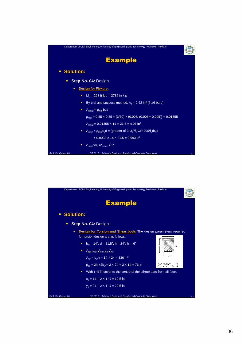
� Solution:
� Step No. 04: Design.
� Design for Torsion and Shear both: The design parameters required
for torsion design are as follows,
� bw = 14″; d = 21.5″; h = 24″; hf = 6″
� Acp, pcp, Aoh, ph, Ao:
Acp = bwh = 14 × 24 = 336 in2
pcp = 2h +2bw = 2 × 24 + 2 × 14 = 76 in
� With 1 ¾ in cover to the centre of the stirrup bars from all faces
xo = 14 – 2 × 1 ¾ = 10.5 in
yo = 24 – 2 × 1 ¾ = 20.5 in
37
Department of Civil Engineering, University of Engineering and Technology Peshawar, Pakistan
Prof. Dr. Qaisar Ali CE 5115 Advance Design of Reinforced Concrete Structures
Example
73
� Solution:
� Step No. 04: Design.
� Design for Torsion and Shear both: The design parameters required
for torsion design are as follows,
� Thus,
Aoh = xoyo = 10.5 × 20.5 = 215.25 in2
Ao = 0.85Aoh = 182.96 in2
ph = 2 (xoh + yoh) = 2 (10.5 + 20.5) = 62 inches
� Finally,
Acp = 336 in2; pcp = 76 inches; Aoh = 215.25 in2; ph = 62 inches; Ao =
182.96 in2
Department of Civil Engineering, University of Engineering and Technology Peshawar, Pakistan
Prof. Dr. Qaisar Ali CE 5115 Advance Design of Reinforced Concrete Structures
Example
74
� Solution:
� Step No. 04: Design.
� Design for Torsion and Shear both: The design parameters required for
torsion design are as follows,
� (i) Check for size of beam: ACI 11.5.3,
√ [{Vu/ (bwd)} 2 + {Tuph/ (1.7Aoh2)} 2] ≤ Φ {2√ (fc′) + 8√ (fc′)}
� Where, Vu and Tu at critical section. Therefore,
√[{57.1/(21.5×12)}2+{28×12×62/(1.7×215.252)}2]≤0.75×10×√ (3000)/1000
0.345 ksi ≤ 0.411 ksi
� Therefore size of the beam is O.K.
38
Department of Civil Engineering, University of Engineering and Technology Peshawar, Pakistan
Prof. Dr. Qaisar Ali CE 5115 Advance Design of Reinforced Concrete Structures
Example
75
� Solution:
� Step No. 04: Design.
� Design for Torsion and Shear both:
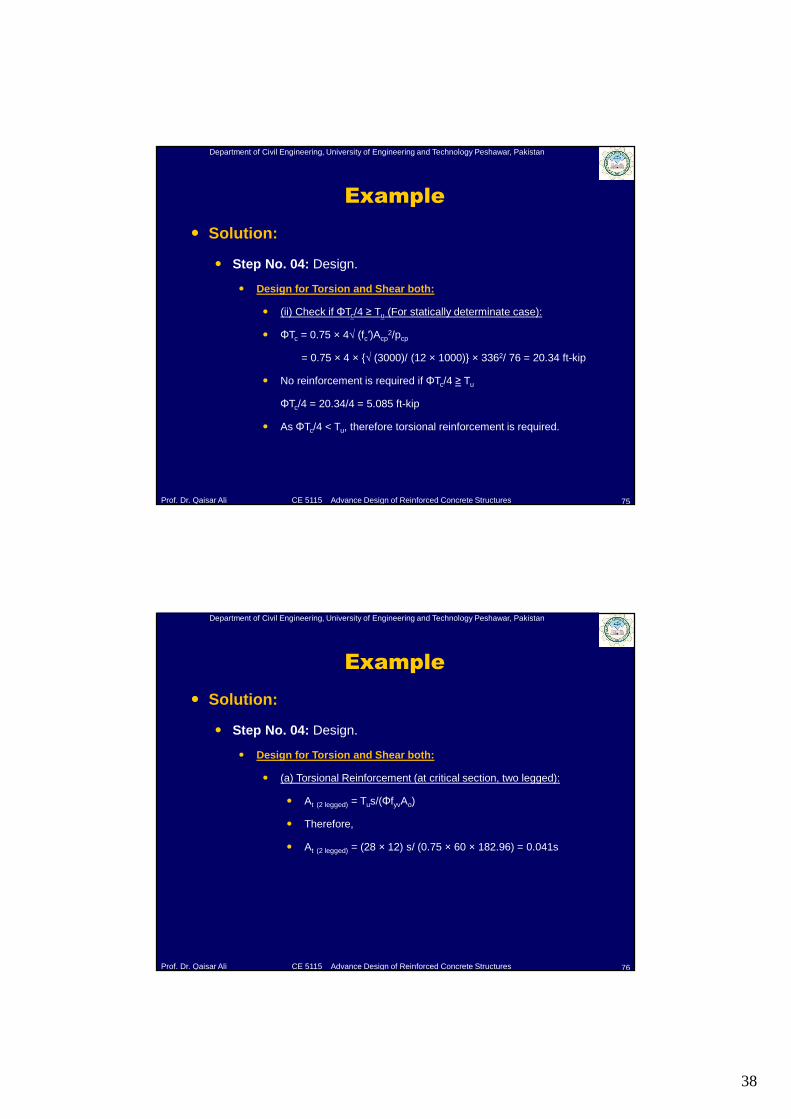
� (ii) Check if ΦTc/4 ≥ Tu (For statically determinate case):
� ΦTc = 0.75 × 4√ (fc′)Acp2/pcp
= 0.75 × 4 × {√ (3000)/ (12 × 1000)} × 3362/ 76 = 20.34 ft-kip
� No reinforcement is required if ΦTc/4 ≥ Tu
ΦTc/4 = 20.34/4 = 5.085 ft-kip
� As ΦTc/4 < Tu, therefore torsional reinforcement is required.
Department of Civil Engineering, University of Engineering and Technology Peshawar, Pakistan
Prof. Dr. Qaisar Ali CE 5115 Advance Design of Reinforced Concrete Structures
Example
76
� Solution:
� Step No. 04: Design.
� Design for Torsion and Shear both:
� (a) Torsional Reinforcement (at critical section, two legged):
� At (2 legged) = Tus/(ΦfyvAo)
� Therefore,
� At (2 legged) = (28 × 12) s/ (0.75 × 60 × 182.96) = 0.041s
39
Department of Civil Engineering, University of Engineering and Technology Peshawar, Pakistan
Prof. Dr. Qaisar Ali CE 5115 Advance Design of Reinforced Concrete Structures
Example
77
� Solution:
� Step No. 04: Design.
� Design for Torsion and Shear both:
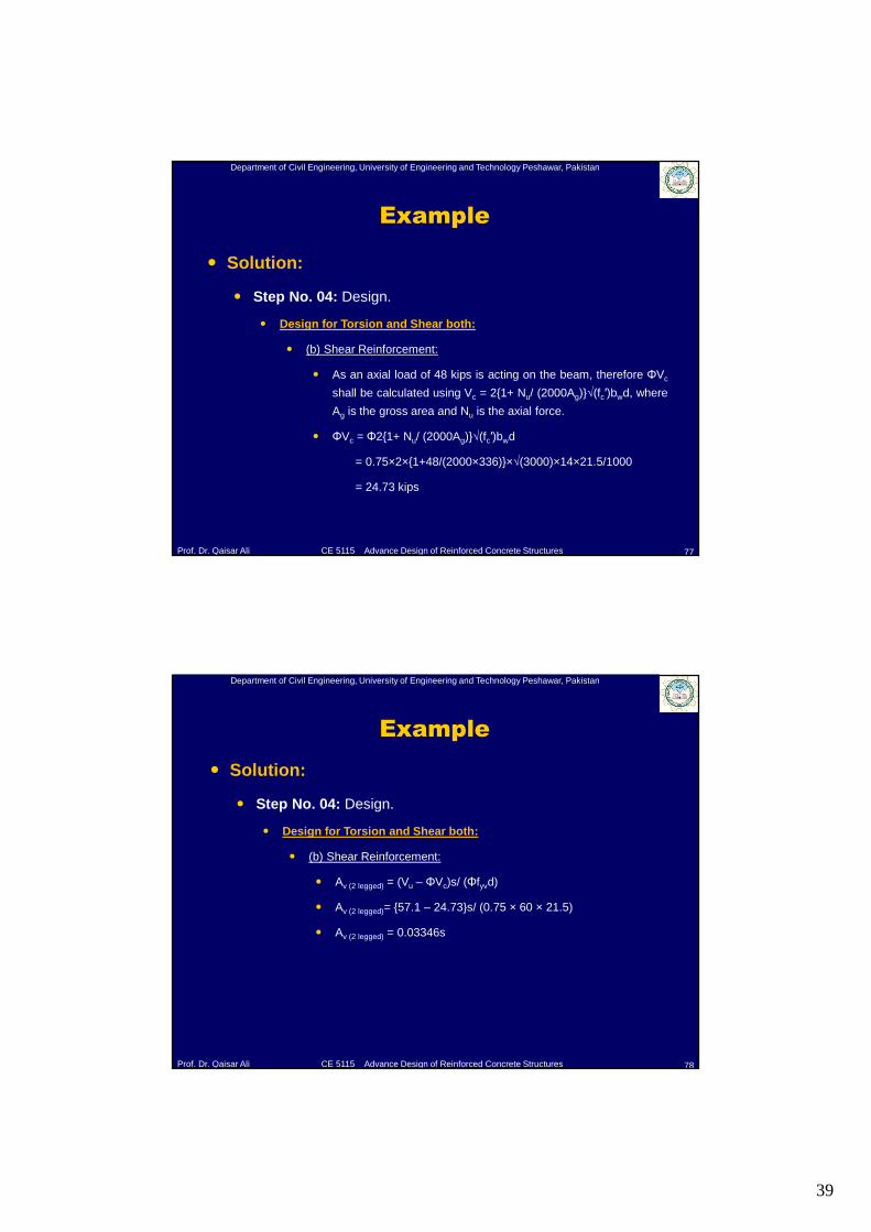
� (b) Shear Reinforcement:
� As an axial load of 48 kips is acting on the beam, therefore ΦVc
shall be calculated using Vc = 2{1+ Nu/ (2000Ag)}√(fc′)bwd, where
Ag is the gross area and Nu is the axial force.
� ΦVc = Φ2{1+ Nu/ (2000Ag)}√(fc′)bwd
= 0.75×2×{1+48/(2000×336)}×√(3000)×14×21.5/1000
= 24.73 kips
Department of Civil Engineering, University of Engineering and Technology Peshawar, Pakistan
Prof. Dr. Qaisar Ali CE 5115 Advance Design of Reinforced Concrete Structures
Example
78
� Solution:
� Step No. 04: Design.
� Design for Torsion and Shear both:
� (b) Shear Reinforcement:
� Av (2 legged) = (Vu – ΦVc)s/ (Φfyvd)
� Av (2 legged)= {57.1 – 24.73}s/ (0.75 × 60 × 21.5)
� Av (2 legged) = 0.03346s
40
Department of Civil Engineering, University of Engineering and Technology Peshawar, Pakistan
Prof. Dr. Qaisar Ali CE 5115 Advance Design of Reinforced Concrete Structures
Example
79
� Solution:
� Step No. 04: Design.
� Design for Torsion and Shear both:
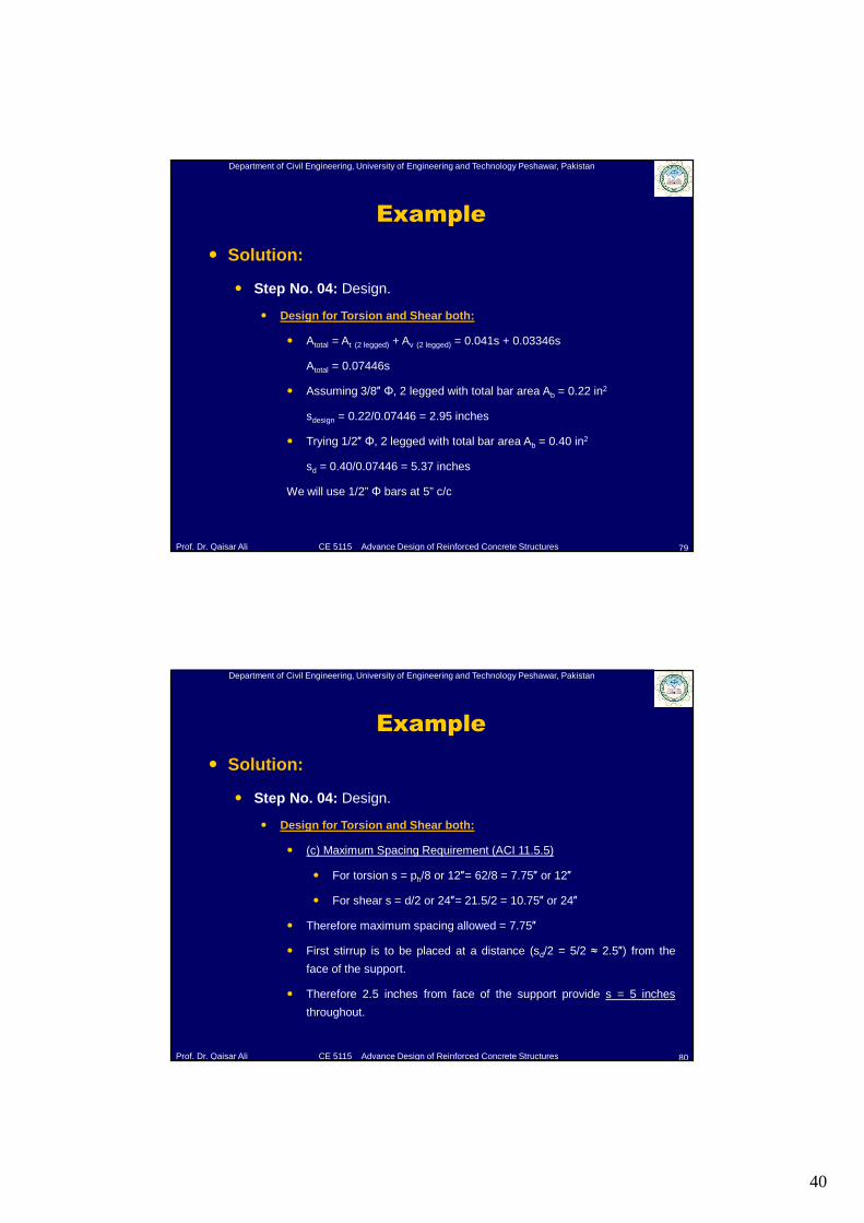
� Atotal = At (2 legged) + Av (2 legged) = 0.041s + 0.03346s
Atotal = 0.07446s
� Assuming 3/8″ Φ, 2 legged with total bar area Ab = 0.22 in2
sdesign = 0.22/0.07446 = 2.95 inches
� Trying 1/2″ Φ, 2 legged with total bar area Ab = 0.40 in2
sd = 0.40/0.07446 = 5.37 inches
We will use 1/2” Φ bars at 5” c/c
Department of Civil Engineering, University of Engineering and Technology Peshawar, Pakistan
Prof. Dr. Qaisar Ali CE 5115 Advance Design of Reinforced Concrete Structures
Example
80
� Solution:
� Step No. 04: Design.
� Design for Torsion and Shear both:
� (c) Maximum Spacing Requirement (ACI 11.5.5)
� For torsion s = ph/8 or 12″= 62/8 = 7.75″ or 12″
� For shear s = d/2 or 24″= 21.5/2 = 10.75″ or 24″
� Therefore maximum spacing allowed = 7.75″
� First stirrup is to be placed at a distance (sd/2 = 5/2 ≈ 2.5″) from the
face of the support.
� Therefore 2.5 inches from face of the support provide s = 5 inches
throughout.
41
Department of Civil Engineering, University of Engineering and Technology Peshawar, Pakistan
Prof. Dr. Qaisar Ali CE 5115 Advance Design of Reinforced Concrete Structures
Example
81
� Solution:
� Step No. 04: Design.
� Design for Torsion and Shear both:
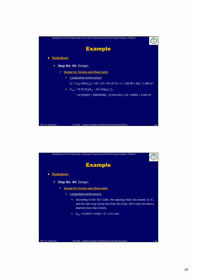
� Longitudinal reinforcement.
Al = Tuph/ (Φ2Aofyl) = 28 × 12 × 62/ (0.75 × 2 × 182.96 × 60) = 1.265 in2
� Almin = 5{√(fc′)/fyl}Acp – (At/ 2s)phfyv/ fyl
= 5{√(3000) × 336/60000} – (0.041s/2s) × 62 × 60/60 = 0.262 in2
Department of Civil Engineering, University of Engineering and Technology Peshawar, Pakistan
Prof. Dr. Qaisar Ali CE 5115 Advance Design of Reinforced Concrete Structures
Example
82
� Solution:
� Step No. 04: Design.
� Design for Torsion and Shear both:
� Longitudinal reinforcement.
� According to the ACI Code, the spacing must not exceed 12 in.,
and the bars may not be less than No.3 (No. 10) in size nor have a
diameter less than 0.042s.
� dmin = 0.042s = 0.042 × 5 = 0.21 inch
42
Department of Civil Engineering, University of Engineering and Technology Peshawar, Pakistan
Prof. Dr. Qaisar Ali CE 5115 Advance Design of Reinforced Concrete Structures
Example
83
� Solution:
� Step No. 04: Design.
� Design for Torsion and Shear both:
� Longitudinal reinforcement.
� Reinforcement will be placed at the top, mid depth, and bottom of the
member, each level to provide not less than 1.265/3 = 0.422 in2. Two
No. 6 bars will be used at mid depth, and reinforcement to be placed for
flexure will be increased by 0.422 in2 at the top and bottom of member.
� Therefore final flexural reinforcement is:
� As, main = 2.62 + 0.422 = 3.042 in2 (7 #6 bars)
� Whereas 2 #6 bars will be provided for bottom and mid depth
reinforcement each.
Department of Civil Engineering, University of Engineering and Technology Peshawar, Pakistan
Prof. Dr. Qaisar Ali CE 5115 Advance Design of Reinforced Concrete Structures
Example
84
� Solution:
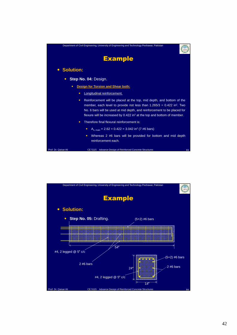
� Step No. 05: Drafting.
54″
(5+2) #6 bars
#4, 2 legged @ 5″ c/c
2 #6 bars24″
14″
2 #6 bars
(5+2) #6 bars
#4, 2 legged @ 5″ c/c
43
Department of Civil Engineering, University of Engineering and Technology Peshawar, Pakistan
Prof. Dr. Qaisar Ali CE 5115 Advance Design of Reinforced Concrete Structures
References
85
� Design of Concrete Structures (13th Ed.) by Nilson, Darwin and
Dolan.
� Reinforced Concrete – Mechanics and Design [5th Ed.] by James
MacGregor.
� ACI 318.
Department of Civil Engineering, University of Engineering and Technology Peshawar, Pakistan
Prof. Dr. Qaisar Ali CE 5115 Advance Design of Reinforced Concrete Structures
The End
86