lecture 1 course introduction - piazza
TRANSCRIPT
ECE 325 OPTOELECTRONICS
Ahmed Farghal, Ph.D.
ECE, Menoufia University
Lecture 1
Course Introduction
February 13, 2019
Kasap–1.1A, 1.2, and 1.3

EC
E 3
25
Sprin
g 2
01
9
Dr. A
hm
ed Farghal
Lecture 1
Course Team
2
Course Instructor: Ahmed Farghal [email protected]
https://www.facebook.com/ahmed.farghal10
Office Hours: TBD
Office: Commun. building – 2nd floor, Room-309.
Open Door Policy: When my door is open, you are welcome to
come in.
TA (Tutorials): Eman Salah Badr
Office Hours: TBD
EC
E 3
25
Sprin
g 2
01
9
Dr. A
hm
ed Farghal
Lecture 1
Course Information
3
Goal: Overview of optoelectronic device technology.
Emphasis: device physics/operating principles (mainly
concepts, less on math), along with some structural engineering.
Selected Topics:
Introduction and Applications of Optoelectronics
Wave Nature of Light: Conceptual Overview
Dielectric Waveguides and Optical Fibers
LEDs, Lasers, and Optical Amplifiers
Photodetectors
Image Sensors: CCD and CMOS
Photovoltaic Devices: Solar Cells
Polarization and Modulation of Light
EC
E 3
25
Sprin
g 2
01
9
Dr. A
hm
ed Farghal
Lecture 1
Course Textbook
4
S. O. Kasap,
Optoelectronics and
Photonics: Principles
and Practices,
international ed.,
Prentice Hall,
2012.
Reference: Mool C. Gupta, John Ballato, The Handbook of
Photonics, 2nd ed, CRC Press, 2007.
A very good book on
optoelectronics. Easier to read and
understand.
Recommended
EC
E 3
25
Sprin
g 2
01
9
Dr. A
hm
ed Farghal
Lecture 1
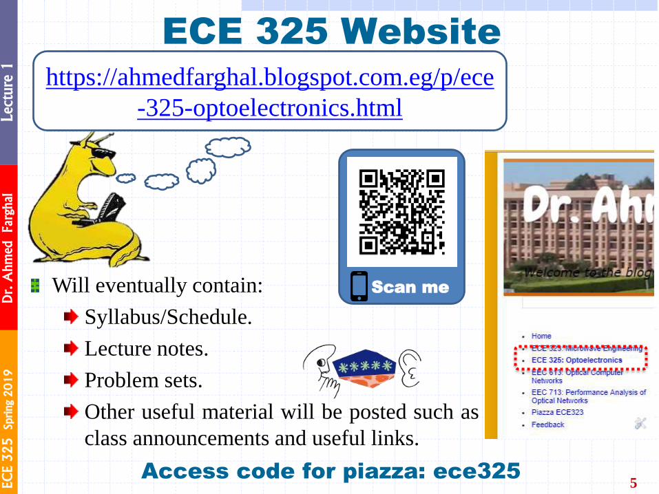
ECE 325 Website
5
Will eventually contain:
Syllabus/Schedule.
Lecture notes.
Problem sets.
Other useful material will be posted such as
class announcements and useful links.
https://ahmedfarghal.blogspot.com.eg/p/ece
-325-optoelectronics.html
Access code for piazza: ece325
Scan me
EC
E 3
25
Sprin
g 2
01
9
Dr. A
hm
ed Farghal
Lecture 1
Lecture Style & Recommendations
6
Lecture notes may have gaps in them that need to be
filled in while you are in lecture (i.e., keep good notes!)
Goal is to facilitate learning
Consider using blank back-side of slides for notes
If you miss a lecture, you will need to ask others for their notes
You can ask me follow up questions once you have
gone through those notes
Be through – The text and the handouts are not encyclopedia
or manual! Each page builds on the previous one – you must read
them completely and in order. When you come to a line,
paragraph or page that you don’t understand, do you stop
and figure it out , or just skip it and go on?
EC
E 3
25
Sprin
g 2
01
9
Dr. A
hm
ed Farghal
Lecture 1
Lecture Style & Recommendations
7
Get help! – Office hours are a great time to learn. All I
ask is that you be knowledgeable of your ignorance!
Be prepared for each lecture – Attend each lecture
having read the notes from the previous lecture, and having
read the relevant text for the current lecture. Come to lecture
prepared to think and learn!
Ask Questions! – I will make an effort to periodically stop and
see if everyone understands the lecture material. However, you should
stop me at any time if you have any questions.
If you are confused about something, chances are so is someone else.

EC
E 3
25
Sprin
g 2
01
9
Dr. A
hm
ed Farghal
Lecture 1
Exams and Cheating
8
Exams are closed-book. HOWEVER
Formula sheet will be provided at midterm and final exams
(if needed) Old Exams and their solutions are on course website
Cheating results in 0 grade and academic dishonesty
Cheating Policy: Just don't

EC
E 3
25
Sprin
g 2
01
9
Dr. A
hm
ed Farghal
Lecture 1
Answer Clarity
9
You must present your answer clearly
Answers with units are to be boxed and right justified.
Show supporting work before the boxed answer with clearly shown steps of how you arrived at the answer.
Grade reduction will occur for sloppy work.
Example of preferred presentation
Problem 1:
Drawing
Equation(s)
Answer = ⋯⋯⋯
EC
E 3
25
Sprin
g 2
01
9
Dr. A
hm
ed Farghal
Lecture 1
10
Let’s enjoy discovering the secrets of Optoelectronics!
I’m hoping to generate insight and interest – not pages of
equations!
EC
E 3
25
Sprin
g 2
01
9
Dr. A
hm
ed Farghal
Lecture 1
Jean-Daniel Colladon and the Light Guiding in a Water Jet
11
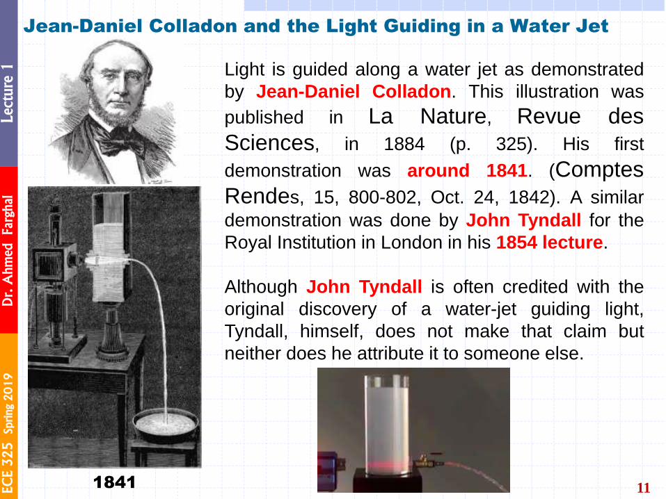
Light is guided along a water jet as demonstrated
by Jean-Daniel Colladon. This illustration was
published in La Nature, Revue des
Sciences, in 1884 (p. 325). His first
demonstration was around 1841. (Comptes
Rendes, 15, 800-802, Oct. 24, 1842). A similar
demonstration was done by John Tyndall for the
Royal Institution in London in his 1854 lecture.
Although John Tyndall is often credited with the
original discovery of a water-jet guiding light,
Tyndall, himself, does not make that claim but
neither does he attribute it to someone else.
1841

EC
E 3
25
Sprin
g 2
01
9
Dr. A
hm
ed Farghal
Lecture 1
12
Water Jet Light Guide
A small hole is made in a plastic bottle full of water to generate
a water jet. When the hole is illuminated with a laser beam
(from a green laser pointer), the light is guided by total internal
reflections along the jet to the tray. Light guiding by a water jet
was demonstrated by Jean-Daniel Colladon in 1841 (Comptes
Rendes, 15, 800-802, Oct. 24, 1842).
EC
E 3
25
Sprin
g 2
01
9
Dr. A
hm
ed Farghal
Lecture 1
Optical Fibers
13
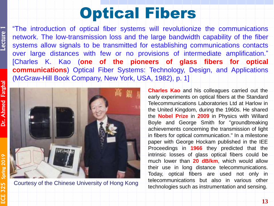
“The introduction of optical fiber systems will revolutionize the communications
network. The low-transmission loss and the large bandwidth capability of the fiber
systems allow signals to be transmitted for establishing communications contacts
over large distances with few or no provisions of intermediate amplification.”
[Charles K. Kao (one of the pioneers of glass fibers for optical
communications) Optical Fiber Systems: Technology, Design, and Applications
(McGraw-Hill Book Company, New York, USA, 1982), p. 1]
Charles Kao and his colleagues carried out the
early experiments on optical fibers at the Standard
Telecommunications Laboratories Ltd at Harlow in
the United Kingdom, during the 1960s. He shared
the Nobel Prize in 2009 in Physics with Willard
Boyle and George Smith for "groundbreaking
achievements concerning the transmission of light
in fibers for optical communication." In a milestone
paper with George Hockam published in the IEE
Proceedings in 1966 they predicted that the
intrinsic losses of glass optical fibers could be
much lower than 20 dB/km, which would allow
their use in long distance telecommunications.
Today, optical fibers are used not only in
telecommunications but also in various other
technologies such as instrumentation and sensing. Courtesy of the Chinese University of Hong Kong
EC
E 3
25
Sprin
g 2
01
9
Dr. A
hm
ed Farghal
Lecture 1
Narinder Singh Kapany
14
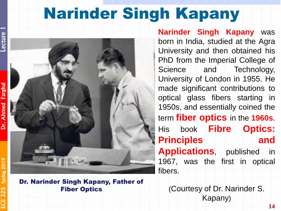
Narinder Singh Kapany was
born in India, studied at the Agra
University and then obtained his
PhD from the Imperial College of
Science and Technology,
University of London in 1955. He
made significant contributions to
optical glass fibers starting in
1950s, and essentially coined the
term fiber optics in the 1960s.
His book Fibre Optics:
Principles and
Applications, published in
1967, was the first in optical
fibers.
(Courtesy of Dr. Narinder S.
Kapany)
Dr. Narinder Singh Kapany, Father of
Fiber Optics
EC
E 3
25
Sprin
g 2
01
9
Dr. A
hm
ed Farghal
Lecture 1
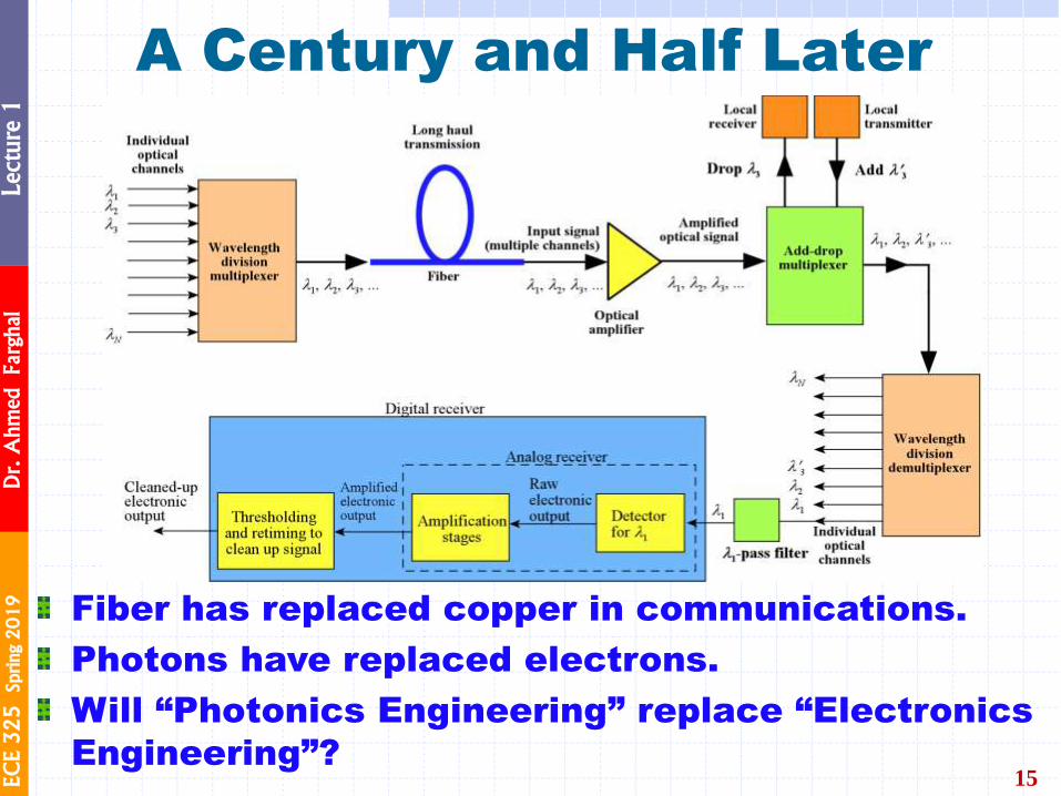
A Century and Half Later
15
Fiber has replaced copper in communications.
Photons have replaced electrons.
Will “Photonics Engineering” replace “Electronics
Engineering”?
EC
E 3
25
Sprin
g 2
01
9
Dr. A
hm
ed Farghal
Lecture 1
Optical Wavelengths
16
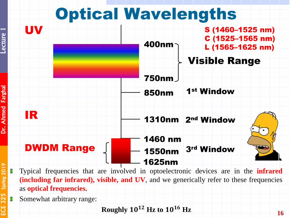
Typical frequencies that are involved in optoelectronic devices are in the infrared
(including far infrared), visible, and UV, and we generically refer to these frequencies
as optical frequencies.
Somewhat arbitrary range:
Roughly 𝟏𝟎𝟏𝟐 Hz to 𝟏𝟎𝟏𝟔 Hz
400nm
750nm
850nm
1310nm
1550nm
Visible Range
IR 2nd Window
3rd Window
1st Window
UV
DWDM Range
1625nm
S (1460–1525 nm)
C (1525–1565 nm)
L (1565–1625 nm)
1460 nm
2
c

EC
E 3
25
Sprin
g 2
01
9
Dr. A
hm
ed Farghal
Lecture 1
Electromagnetic Frequency Spectrum
17
EC
E 3
25
Sprin
g 2
01
9
Dr. A
hm
ed Farghal
Lecture 1
18 htt
ps:
//w
ww
.art
hit
ectu
ral.
com
/wp
-co
nte
nt/
up
load
s/20
13
/04/0
2-T
AB
LE
-OF
-OP
TIC
KS
-SIR
-IS
AA
C-N
EW
TO
N-1
70
4.j
pg
IS OPTICS? WHAT
EC
E 3
25
Sprin
g 2
01
9
Dr. A
hm
ed Farghal
Lecture 1
Optics
19
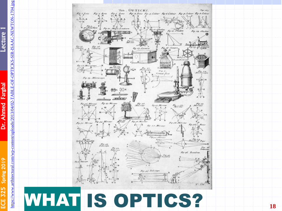
Optics is light at work
Optics is an old subject involving the generation, propagation &
detection of light.
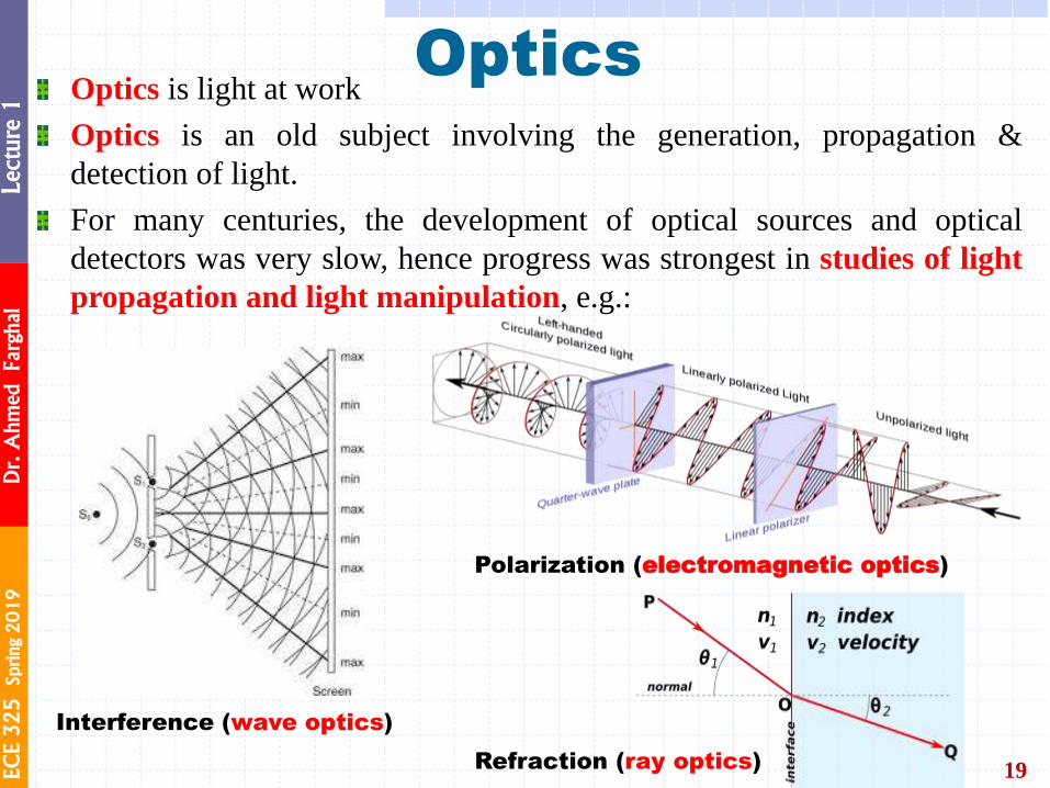
For many centuries, the development of optical sources and optical
detectors was very slow, hence progress was strongest in studies of light
propagation and light manipulation, e.g.:
The Handbook of Photonics, Second
Edition edited by Mool C. Gupta, John Ballato
Refraction (ray optics)
Polarization (electromagnetic optics)
Interference (wave optics)
EC
E 3
25
Sprin
g 2
01
9
Dr. A
hm
ed Farghal
Lecture 1
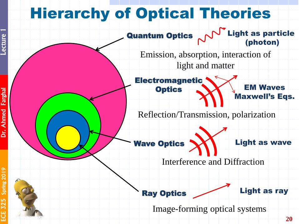
Hierarchy of Optical Theories
20
Ray Optics
Wave Optics
Electromagnetic
Optics
Quantum Optics Light as particle
(photon)
EM Waves
Maxwell’s Eqs.
Light as wave
Light as ray
Emission, absorption, interaction of
light and matter
Reflection/Transmission, polarization Scalar Wave
Interference and Diffraction
Image-forming optical systems
EC
E 3
25
Sprin
g 2
01
9
Dr. A
hm
ed Farghal
Lecture 1
Optics
21
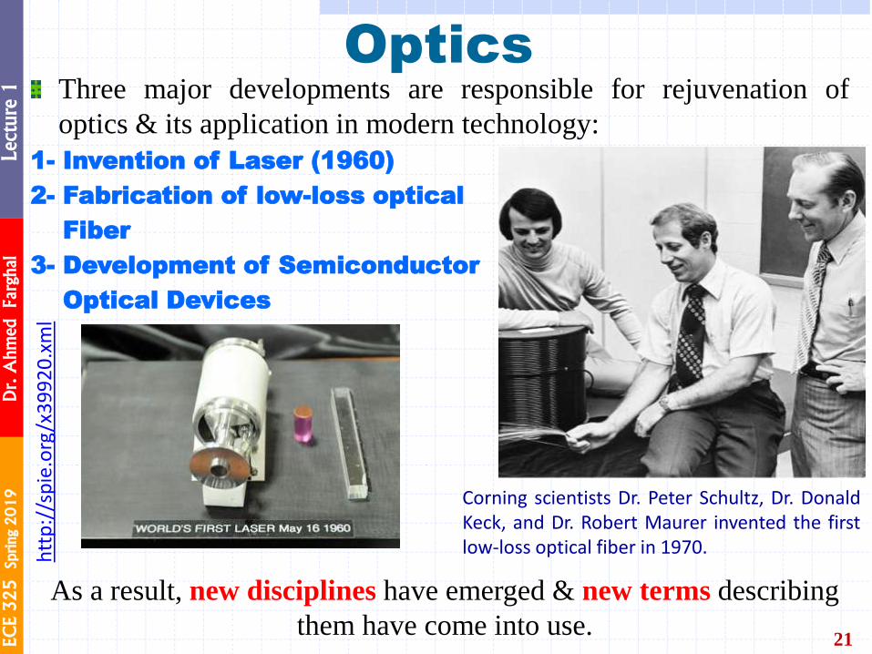
Three major developments are responsible for rejuvenation of
optics & its application in modern technology:
1- Invention of Laser (1960)
2- Fabrication of low-loss optical
Fiber
3- Development of Semiconductor
Optical Devices
Corning scientists Dr. Peter Schultz, Dr. Donald Keck, and Dr. Robert Maurer invented the first low-loss optical fiber in 1970.
As a result, new disciplines have emerged & new terms describing
them have come into use.
htt
p:/
/sp
ie.o
rg/x
39
92
0.x
ml
EC
E 3
25
Sprin
g 2
01
9
Dr. A
hm
ed Farghal
Lecture 1
22 IS PHOTONICS? WHAT

EC
E 3
25
Sprin
g 2
01
9
Dr. A
hm
ed Farghal
Lecture 1
Photonics
23
Photonics reflects the importance of the photon nature of light.
Photonics & electronics clearly overlap since electrons often control the flow of photons & conversely, photons control the flow of electrons.
The scope of Photonics:
1. Generation of Light (coherent & incoherent).
2. Transmission of Light (through free space, fibers, imaging
systems, waveguides, … ).
3. Processing of Light Signals (modulation, switching, amplification, frequency conversion, …).
4. Detection of Light (coherent & incoherent).
Photonic Communications: describes the applications of photonic technology in communication devices & systems, such as transmitters, transmission media, receivers & signal processors.
EC
E 3
25
Sprin
g 2
01
9
Dr. A
hm
ed Farghal
Lecture 1
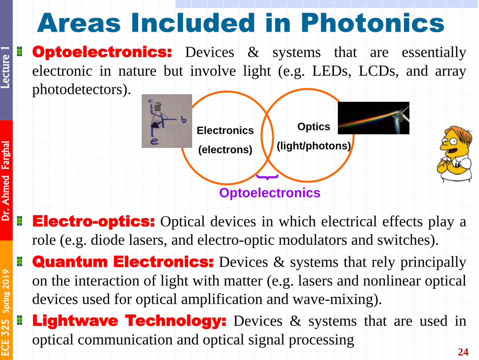
Areas Included in Photonics
24
Optoelectronics: Devices & systems that are essentially
electronic in nature but involve light (e.g. LEDs, LCDs, and array
photodetectors).
Electro-optics: Optical devices in which electrical effects play a
role (e.g. diode lasers, and electro-optic modulators and switches).
Quantum Electronics: Devices & systems that rely principally
on the interaction of light with matter (e.g. lasers and nonlinear optical
devices used for optical amplification and wave-mixing).
Lightwave Technology: Devices & systems that are used in
optical communication and optical signal processing
Electronics
(electrons)
Optics
(light/photons)
Optoelectronics
EC
E 3
25
Sprin
g 2
01
9
Dr. A
hm
ed Farghal
Lecture 1
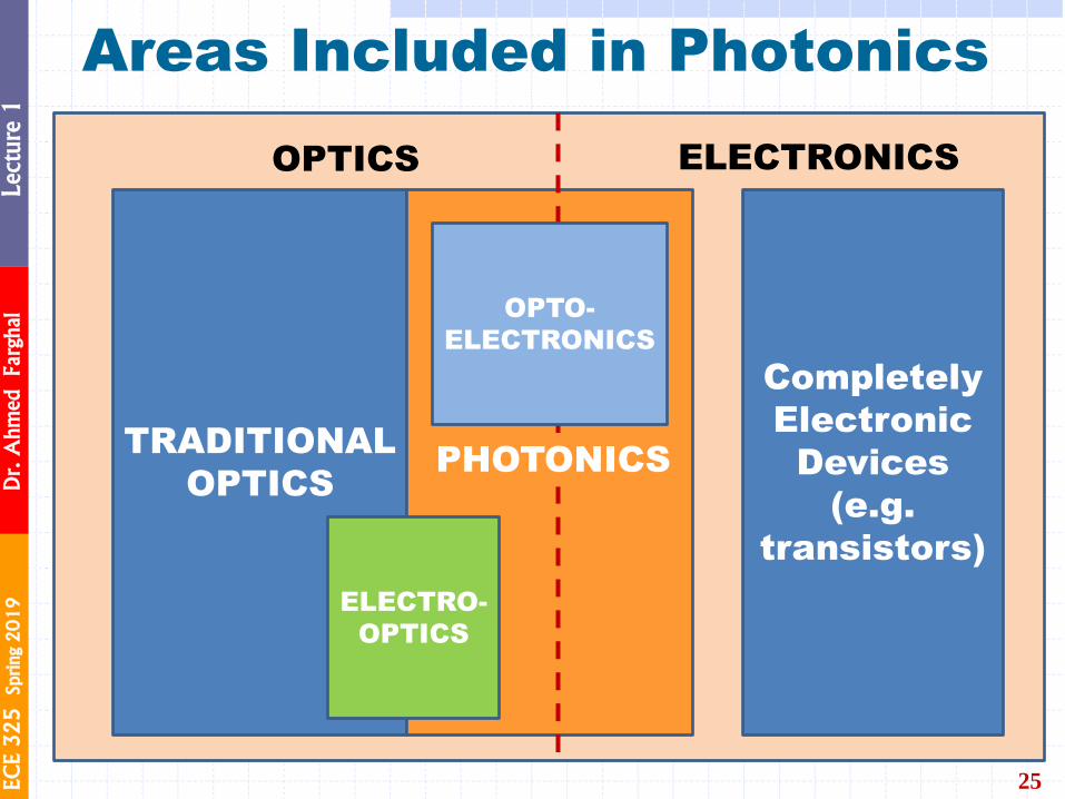
Areas Included in Photonics
25
Completely
Electronic
Devices
(e.g.
transistors)
ELECTRONICS OPTICS
TRADITIONAL
OPTICS
OPTO-
ELECTRONICS
ELECTRO-
OPTICS
PHOTONICS
EC
E 3
25
Sprin
g 2
01
9
Dr. A
hm
ed Farghal
Lecture 1
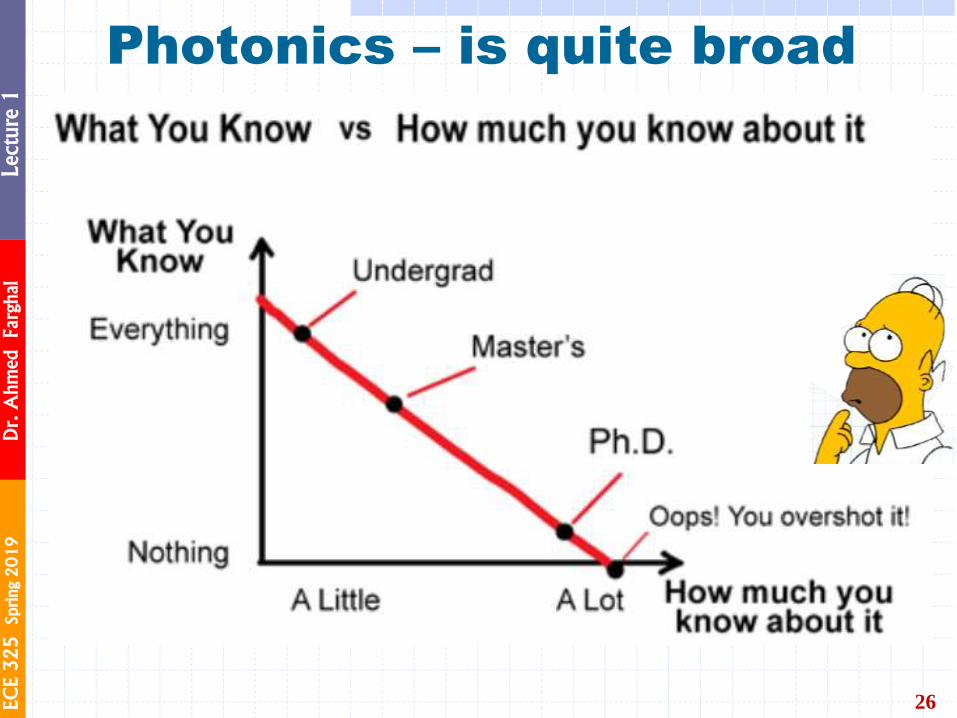
Photonics – is quite broad
26

EC
E 3
25
Sprin
g 2
01
9
Dr. A
hm
ed Farghal
Lecture 1
27
Photonics is now an important part of the world economy,
with multiple applications
OF PHOTONICS APPLICATIONS
EC
E 3
25
Sprin
g 2
01
9
Dr. A
hm
ed Farghal
Lecture 1
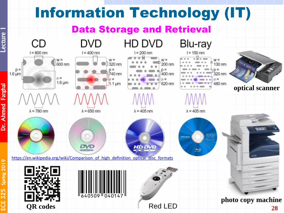
Information Technology (IT)
28
Data Storage and Retrieval
https://en.wikipedia.org/wiki/Comparison_of_high_definition_optical_disc_formats
QR codes Red LED photo copy machine
optical scanner
EC
E 3
25
Sprin
g 2
01
9
Dr. A
hm
ed Farghal
Lecture 1
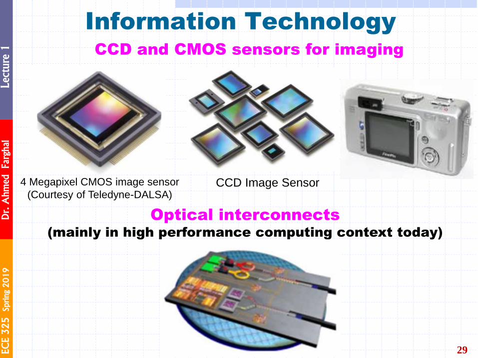
Information Technology
29
CCD and CMOS sensors for imaging
4 Megapixel CMOS image sensor
(Courtesy of Teledyne-DALSA) CCD Image Sensor
Optical interconnects (mainly in high performance computing context today)
EC
E 3
25
Sprin
g 2
01
9
Dr. A
hm
ed Farghal
Lecture 1
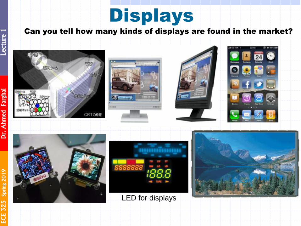
Can you tell how many kinds of displays are found in the market?
Displays
LED for displays
EC
E 3
25
Sprin
g 2
01
9
Dr. A
hm
ed Farghal
Lecture 1
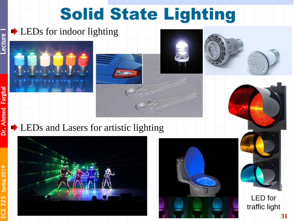
31
Solid State Lighting LEDs for indoor lighting
LED for
traffic light
LEDs and Lasers for artistic lighting
EC
E 3
25
Sprin
g 2
01
9
Dr. A
hm
ed Farghal
Lecture 1
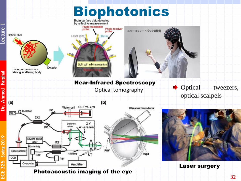
Biophotonics
32
Near-Infrared Spectroscopy
https://www.ssi.shimadzu.com/products/product.cfm?product=labnirs_2
Fig. 5. (a) An optical scanning PAOM combined with OCT. (b) Illustration of ultrasonic transducer position and how the optical illumination beam enters the eye and focuses on the retina. SLD: superluminescent diode, OCT: optical coherence tomography, PC: polarization controller, CCD: charge coupled device, Pd: photodiode, UT ultrasonic transducer, FOV: field of view
https://www.sciencedirect.com/science/article/pii/S2213597916300180
Photoacoustic imaging of the eye
Optical tweezers,
optical scalpels
Laser surgery
Optical tomography
EC
E 3
25
Sprin
g 2
01
9
Dr. A
hm
ed Farghal
Lecture 1
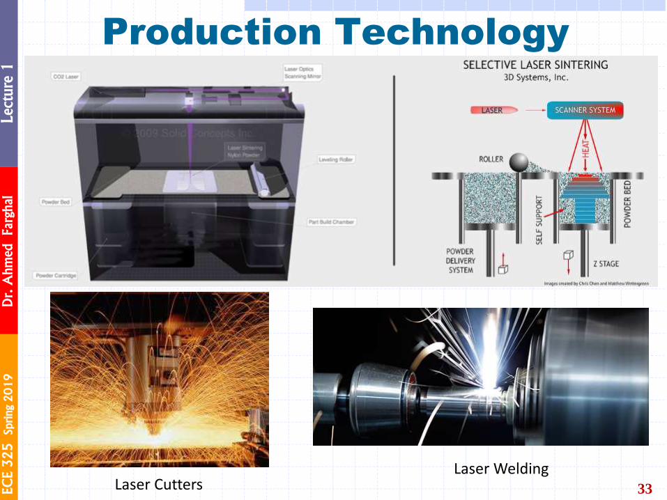
Production Technology
33 Laser Cutters Laser Welding
EC
E 3
25
Sprin
g 2
01
9
Dr. A
hm
ed Farghal
Lecture 1
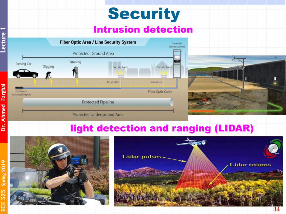
Security
34
Security
Intrusion detection
Laser radar (LIDAR)
Intrusion detection
light detection and ranging (LIDAR)
EC
E 3
25
Sprin
g 2
01
9
Dr. A
hm
ed Farghal
Lecture 1
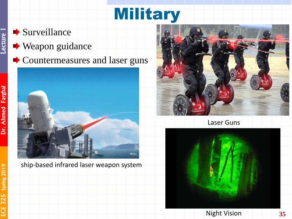
Military
35
Surveillance
Weapon guidance
Countermeasures and laser guns
ship-based infrared laser weapon system
Laser Guns
Night Vision
EC
E 3
25
Sprin
g 2
01
9
Dr. A
hm
ed Farghal
Lecture 1
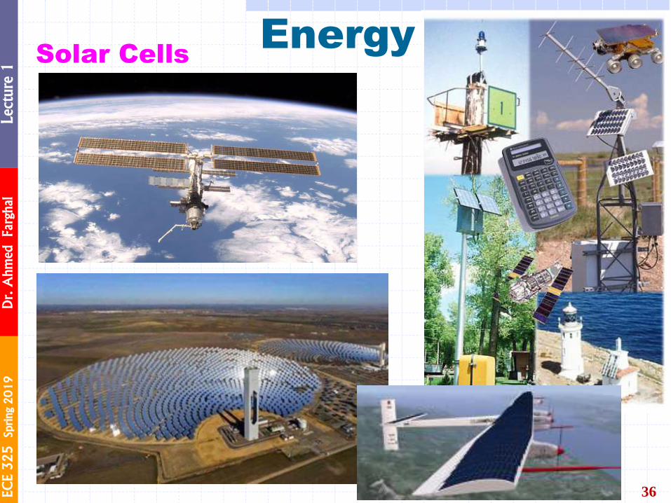
Energy
36
Solar Cells
EC
E 3
25
Sprin
g 2
01
9
Dr. A
hm
ed Farghal
Lecture 1
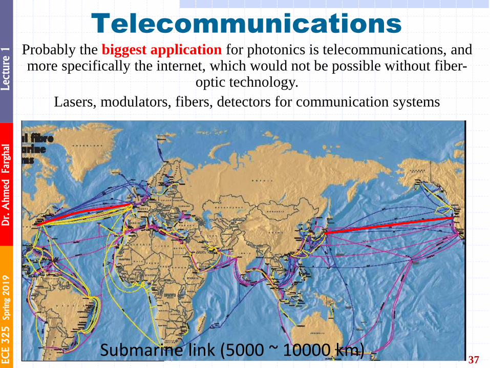
Telecommunications
37
Probably the biggest application for photonics is telecommunications, and more specifically the internet, which would not be possible without fiber-
optic technology.
Lasers, modulators, fibers, detectors for communication systems
Submarine link (5000 ~ 10000 km)
Telecommunication
Lasers, modulators, fibers,
detectors for communication
systems
EC
E 3
25
Sprin
g 2
01
9
Dr. A
hm
ed Farghal
Lecture 1
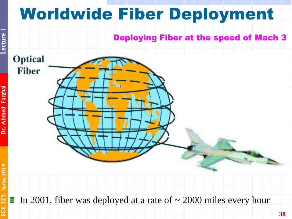
Worldwide Fiber Deployment
38
In 2001, fiber was deployed at a rate of ~ 2000 miles every hour
Deploying Fiber at the speed of Mach 3
EC
E 3
25
Sprin
g 2
01
9
Dr. A
hm
ed Farghal
Lecture 1
39
EC
E 3
25
Sprin
g 2
01
9
Dr. A
hm
ed Farghal
Lecture 1
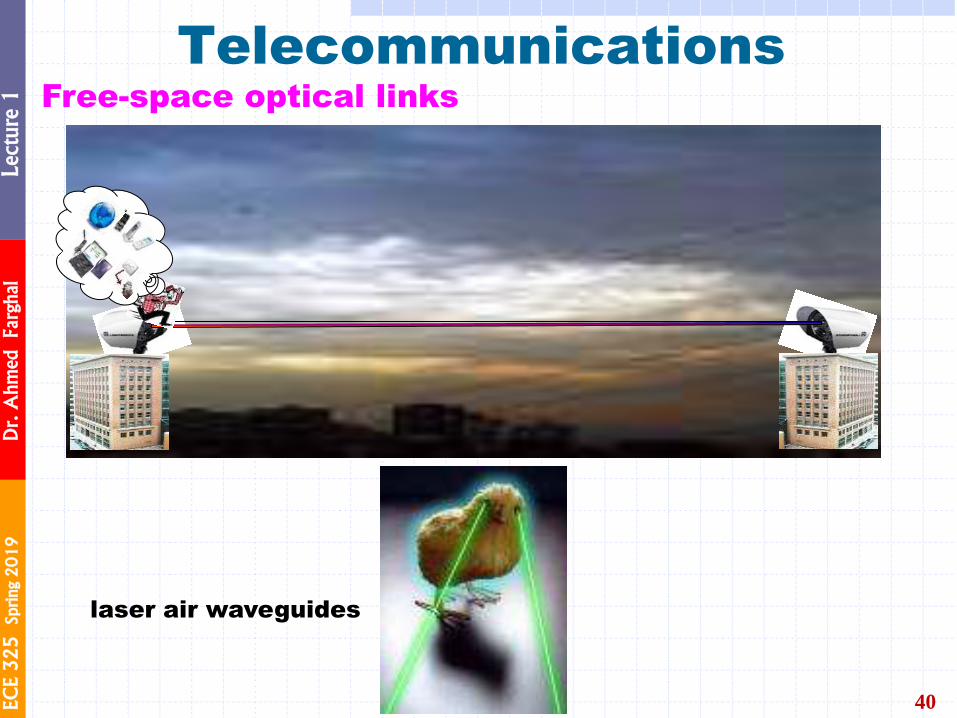
40
Telecommunications Free-space optical links
laser air waveguides

EC
E 3
25
Sprin
g 2
01
9
Dr. A
hm
ed Farghal
Lecture 1
41
Because of its widespread, optics plays an important
role in the global economy.
Innovation = Invention × Commercialization
INDUSTRY PHOTONICS

EC
E 3
25
Sprin
g 2
01
9
Dr. A
hm
ed Farghal
Lecture 1
The Photonics Industry
42
EC
E 3
25
Sprin
g 2
01
9
Dr. A
hm
ed Farghal
Lecture 1
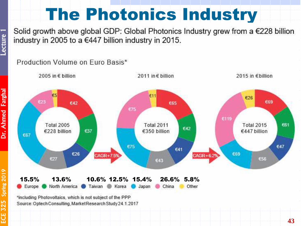
The Photonics Industry
43
Photonics production is mainly located in Asia. Nearly 70% are accounted for by China, Japan, Korea, Taiwan, and a few other Asian countries including the Philippines, Malaysia, Singapore, Thailand and India. Europe and North America account for 15.5% and 13.6%, respectively. Other Photonics producing countries include Israel, Turkey, Australia, South Africa, and Brazil.
26.6% 5.8% 15.5% 13.6% 10.6% 12.5% 15.4%
EC
E 3
25
Sprin
g 2
01
9
Dr. A
hm
ed Farghal
Lecture 1
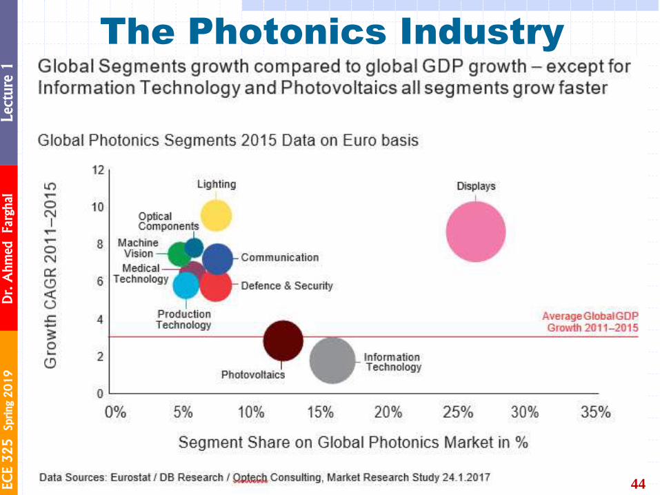
The Photonics Industry
44
EC
E 3
25
Sprin
g 2
01
9
Dr. A
hm
ed Farghal
Lecture 1
Question For Thoughts
45
What will happen in the field of Photonics in 10, 20, 50 years?
What is the area of Photonics that you are going to work in?
Can we replace Electronics with Photonics?
Can you create a new research area in Photonics? New Industry?
What are the photonics devices that you think have improved your
life?
What is the Photonics device that you think would be great to have
but does not exist?
EC
E 3
25
Sprin
g 2
01
9
Dr. A
hm
ed Farghal
Lecture 1
46
NATURE OF LIGHT WAVE
EC
E 3
25
Sprin
g 2
01
9
Dr. A
hm
ed Farghal
Lecture 1
Light as an EM Wave
47
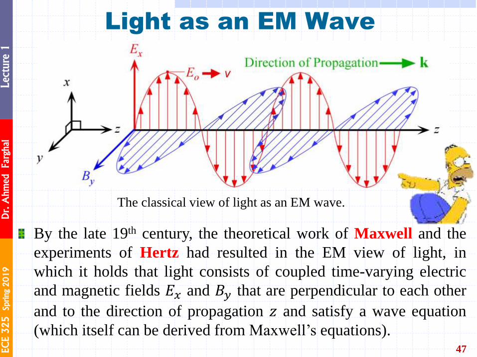
By the late 19th century, the theoretical work of Maxwell and the
experiments of Hertz had resulted in the EM view of light, in
which it holds that light consists of coupled time-varying electric
and magnetic fields 𝐸𝑥 and 𝐵𝑦 that are perpendicular to each other
and to the direction of propagation 𝑧 and satisfy a wave equation
(which itself can be derived from Maxwell’s equations).
The classical view of light as an EM wave.
EC
E 3
25
Sprin
g 2
01
9
Dr. A
hm
ed Farghal
Lecture 1
Light as an EM Wave
48
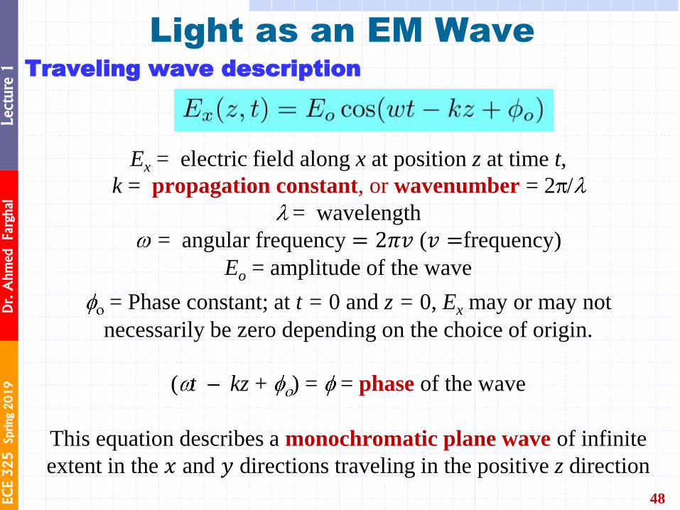
Traveling wave description
Ex = electric field along x at position z at time t,
k = propagation constant, or wavenumber = 2 /
= wavelength
= angular frequency = 2𝜋𝑣 (𝑣 =frequency)
Eo = amplitude of the wave
= Phase constant; at t = 0 and z = 0, Ex may or may not
necessarily be zero depending on the choice of origin.
( t kz + ) = = phase of the wave
This equation describes a monochromatic plane wave of infinite
extent in the 𝑥 and 𝑦 directions traveling in the positive z direction
Thus, there is a similar traveling wave equation for the magnetic
field component By. We generally describe the interaction of a
light wave with a non-conducting matter (conductivity, 𝜎 = 0)
through the electric field component Ex rather than By because it
is the electric field that displaces the electrons in molecules or
ions in the crystal and thereby gives rise to the polarization of
matter. However, the two fields are linked, as in Figure 1.1, and
there is an intimate relationship between them. The optical field
refers to the electric field Ex.
Ex = Eo cos( t kz + )
A plane wave is a solution of Maxwell’s wave equation
Substitute into Maxwell’s Equation to show that this is a solution.
EC
E 3
25
Sprin
g 2
01
9
Dr. A
hm
ed Farghal
Lecture 1
49
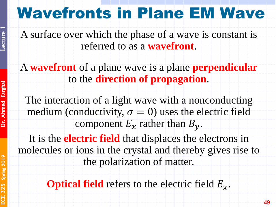
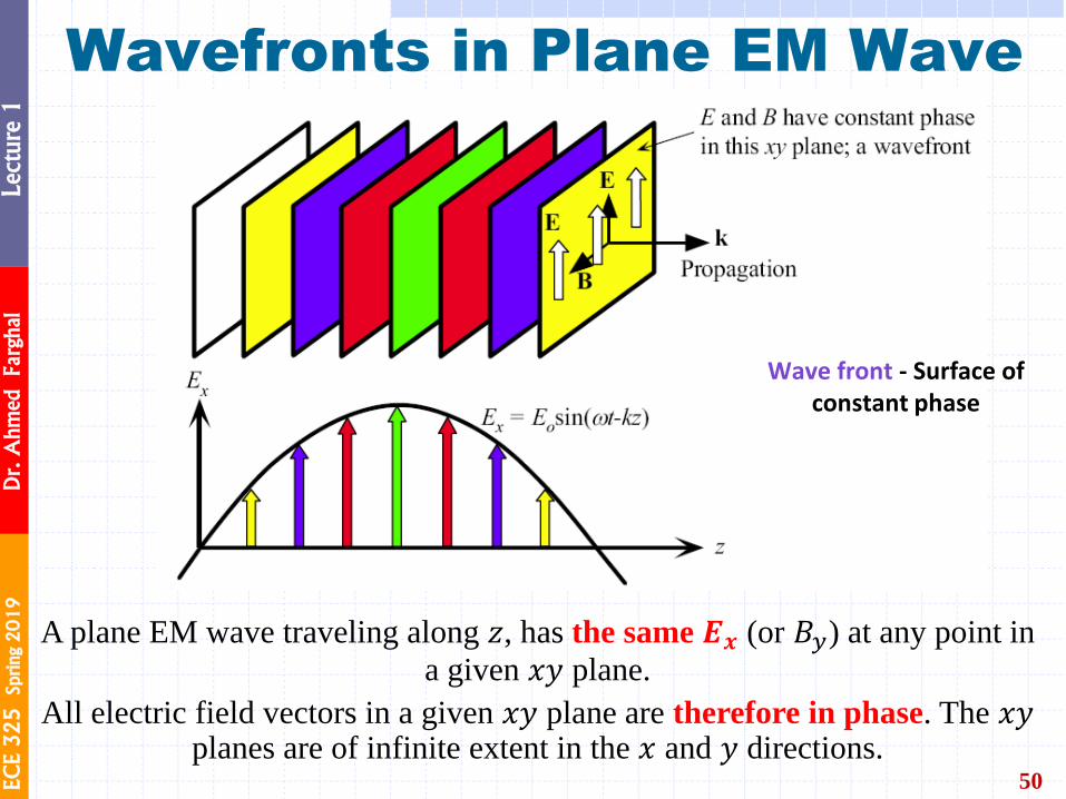
A surface over which the phase of a wave is constant is referred to as a wavefront.
A wavefront of a plane wave is a plane perpendicular to the direction of propagation.
The interaction of a light wave with a nonconducting medium (conductivity, 𝜎 = 0) uses the electric field
component 𝐸𝑥 rather than 𝐵𝑦.
It is the electric field that displaces the electrons in molecules or ions in the crystal and thereby gives rise to
the polarization of matter.
Optical field refers to the electric field 𝐸𝑥.
Wavefronts in Plane EM Wave
EC
E 3
25
Sprin
g 2
01
9
Dr. A
hm
ed Farghal
Lecture 1
Wavefronts in Plane EM Wave
50
A plane EM wave traveling along 𝑧, has the same 𝑬𝒙 (or 𝐵𝑦) at any point in
a given 𝑥𝑦 plane.
All electric field vectors in a given 𝑥𝑦 plane are therefore in phase. The 𝑥𝑦 planes are of infinite extent in the 𝑥 and 𝑦 directions.
Rays – lines perpendicular to wave fronts
Wave front - Surface of constant phase
Wave front - Surface of constant phase
EC
E 3
25
Sprin
g 2
01
9
Dr. A
hm
ed Farghal
Lecture 1
Phase Velocity
51
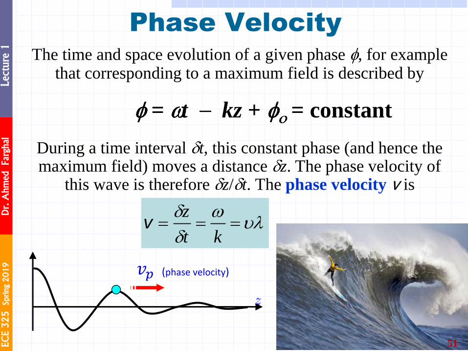
The time and space evolution of a given phase , for example that corresponding to a maximum field is described by
= t kz + = constant
During a time interval t, this constant phase (and hence the maximum field) moves a distance z. The phase velocity of
this wave is therefore z/ t. The phase velocity v is
kt
zv
Phase velocity 𝑣𝑝 : velocity at
which a fixed phase point on the
wave travels.
𝑣𝑝 (phase velocity)
Consider “riding” one part of the wave
Phase velocity calculation
Hence

EC
E 3
25
Sprin
g 2
01
9
Dr. A
hm
ed Farghal
Lecture 1
Wave Motion
52
o 𝐸𝑥 𝑧, 𝑡 = 𝐸𝑜 cos 𝜔𝑡 − 𝑘𝑧 + 𝜙𝑜 = 𝐸𝑜 cos 𝜔 𝑡 −𝑘
𝜔𝑧 + 𝜙𝑜
o 𝐸𝑥 𝑧, 𝑡 = 𝑓 𝑡 −𝑧
𝑉
Let 𝑉 = 1 m/s
At 𝒕 = 𝟏 s, focus on the peak located at 𝑧 = 1.5 m
⟹ 𝑆 = 𝑡 −𝑧
𝑉= 1 −
1.5
1= −0.5
The argument 𝑆 stays constant for varying 𝑡 & 𝑧 ⟹ at 𝒕 = 𝟐 s, for example:
𝑆 = −0.5 = 𝑡 −𝑧
𝑉= 2 −
𝑧
1 ⟹ 𝑧 = 2.5 m.
So, the peak has now moved to position 𝑧 = 2.5 m at 𝑡 = 2 s.
Likewise, every point on this function moves the same distance (1 m) in this time (1
s). ⟹ This is called wave motion.
The speed of this movement is: δ𝑧
δ𝑡=
1 m1 s
= 1 m s = 𝑉
𝐸𝑥 𝑧, 𝑡
EC
E 3
25
Sprin
g 2
01
9
Dr. A
hm
ed Farghal
Lecture 1
Phase change over a distance ∆z
53
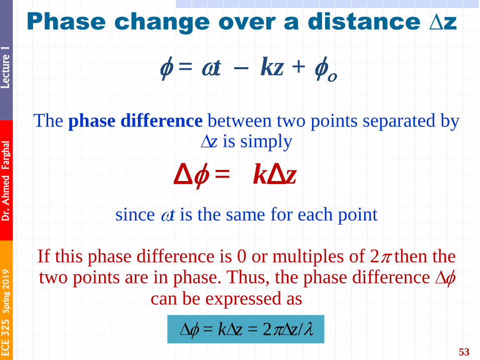
The phase difference between two points separated by z is simply
since t is the same for each point
If this phase difference is 0 or multiples of 2 then the two points are in phase. Thus, the phase difference
can be expressed as
= t kz +
D = kDz
= k z = 2 z/
EC
E 3
25
Sprin
g 2
01
9
Dr. A
hm
ed Farghal
Lecture 1
Exponential Notation
54
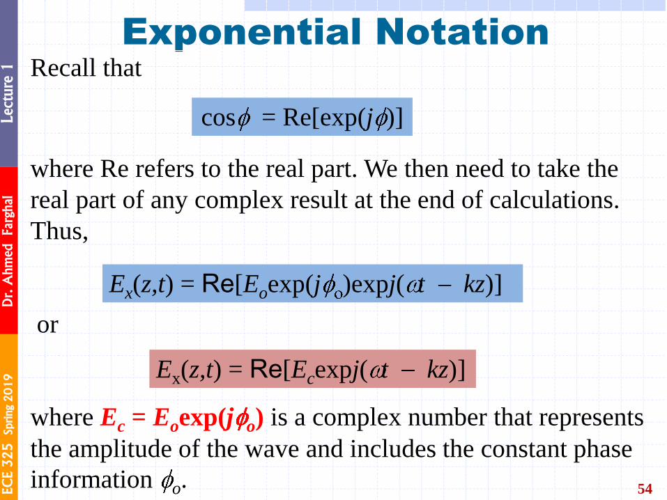
Recall that
where Re refers to the real part. We then need to take the
real part of any complex result at the end of calculations.
Thus,
or
where Ec = Eoexp(j o) is a complex number that represents
the amplitude of the wave and includes the constant phase
information o.
cos = Re[exp(j )]
Ex(z,t) = Re[Eoexp(j )expj( t kz)]
Ex(z,t) = Re[Ecexpj( t kz)]

EC
E 3
25
Sprin
g 2
01
9
Dr. A
hm
ed Farghal
Lecture 1
Wave Vector k
55
Direction of propagation is indicated with a vector k, called the wave
vector, whose magnitude is the propagation constant, k = 2 / .
k is perpendicular to constant phase planes.
If propagation is along z, k r becomes kz.
In general, if k has components kx, ky and kz along x, y and z, then
from the definition of the dot product, k r = kxx + kyy + kzz.
https://en.wikipedia.org/wiki/Wave_vector https://www.mathsisfun.com/algebra/vectors-dot-product.html
When the EM wave is propagating along
some arbitrary direction k, then the electric
field E(r,t) at a point r on a plane
perpendicular to k is
A traveling plane EM wave along a
direction k
E (r,t) = Eocos( t k r + )
EC
E 3
25
Sprin
g 2
01
9
Dr. A
hm
ed Farghal
Lecture 1
Refractive Index
56
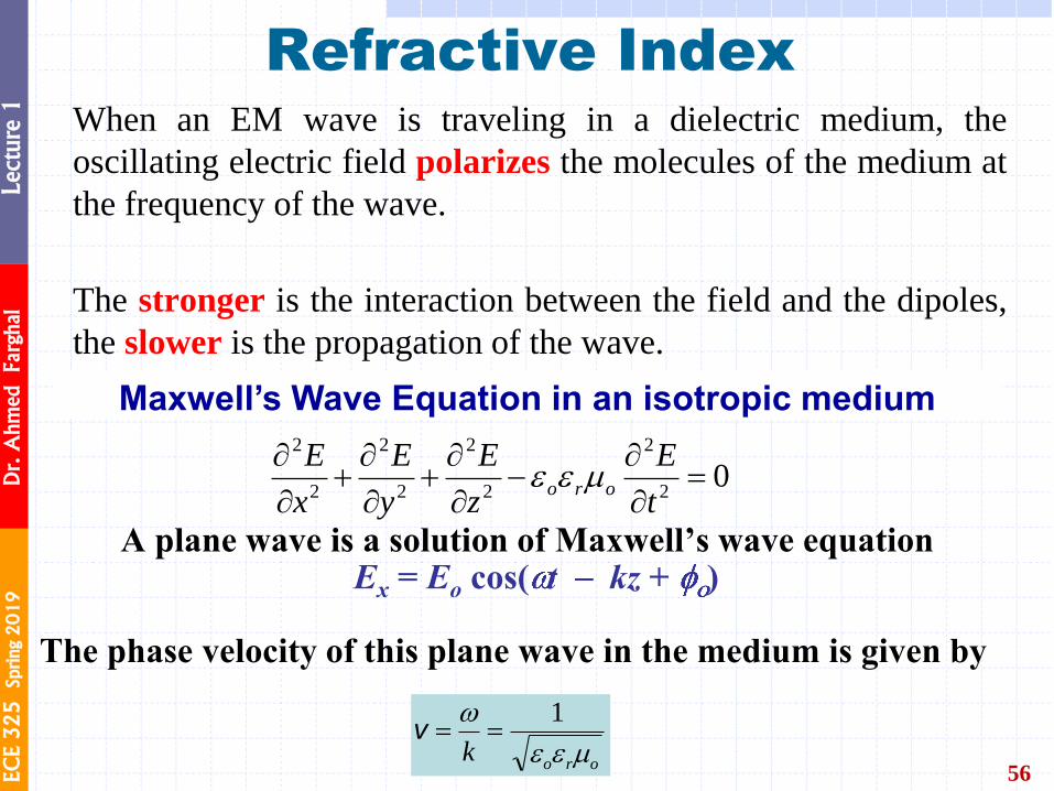
When an EM wave is traveling in a dielectric medium, the
oscillating electric field polarizes the molecules of the medium at
the frequency of the wave.
The stronger is the interaction between the field and the dipoles,
the slower is the propagation of the wave.
Maxwell’s Wave Equation in an isotropic medium
02
2
2
2
2
2
2
2
t
E
z
E
y
E
x
Eoro
Ex = Eo cos( t kz + ) A plane wave is a solution of Maxwell’s wave equation
orok
1v
The phase velocity of this plane wave in the medium is given by
EC
E 3
25
Sprin
g 2
01
9
Dr. A
hm
ed Farghal
Lecture 1
Phase Velocity and er
57
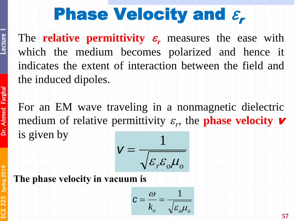
The relative permittivity r measures the ease with
which the medium becomes polarized and hence it
indicates the extent of interaction between the field and
the induced dipoles.
For an EM wave traveling in a nonmagnetic dielectric
medium of relative permittivity r, the phase velocity v
is given by
oor
1ν
The phase velocity in vacuum is
oook
1c
EC
E 3
25
Sprin
g 2
01
9
Dr. A
hm
ed Farghal
Lecture 1
Refractive Index
58
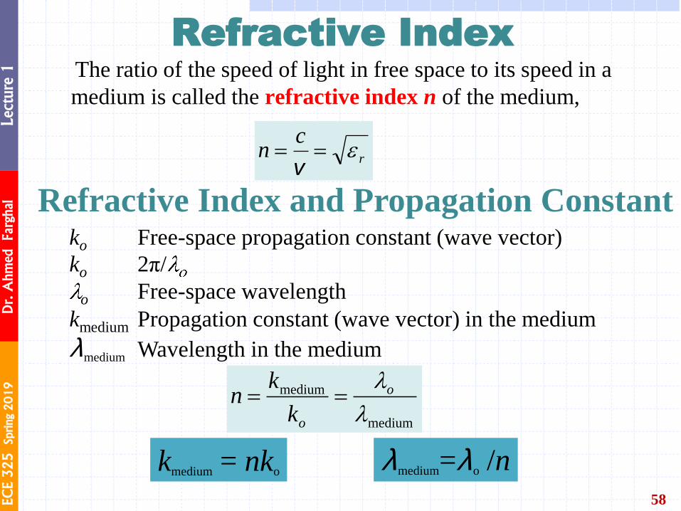
The ratio of the speed of light in free space to its speed in a
medium is called the refractive index n of the medium,
r
cn
v
medium
medium
o
ok
kn
In non-crystalline materials such as glasses and liquids, the material
structure is the same in all directions and n does not depend on the
direction. The refractive index is then isotropic
Refractive Index and Propagation Constant
Crystals, in general, have nonisotropic, or anisotropic,
properties.
Typically noncrystalline solids such as glasses and liquids,
and cubic crystals are optically isotropic; they possess only
one refractive index for all directions.
Refractive Index and Isotropy
lmedium=lo /n kmedium = nko
ko Free-space propagation constant (wave vector)
ko 2π/
o Free-space wavelength
kmedium Propagation constant (wave vector) in the medium
lmedium Wavelength in the medium
Refractive Index and Propagation Constant
EC
E 3
25
Sprin
g 2
01
9
Dr. A
hm
ed Farghal
Lecture 1
Refractive Index and Wavelength
59
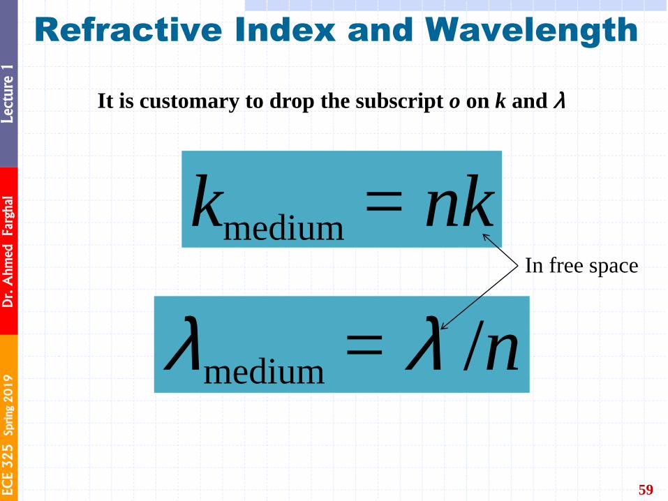
lmedium = l /n
kmedium = nk In free space
It is customary to drop the subscript o on k and l
EC
E 3
25
Sprin
g 2
01
9
Dr. A
hm
ed Farghal
Lecture 1
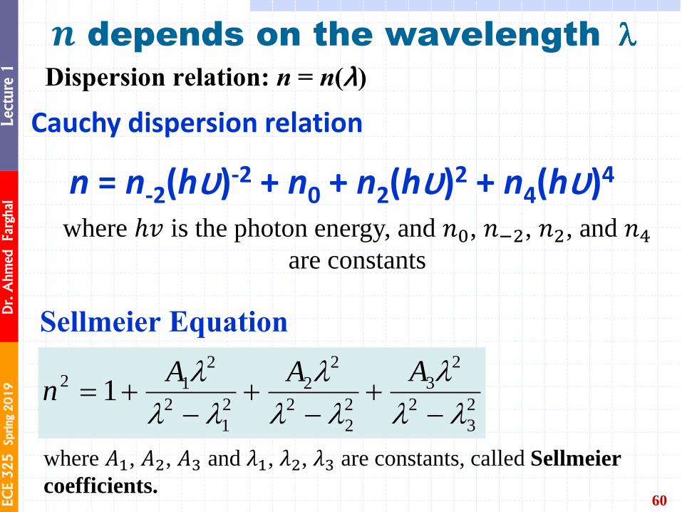
𝒏 depends on the wavelength
60
n = n-2(hu)-2 + n0 + n2(hu)2 + n4(hu)4
Cauchy dispersion relation
where ℎ𝑣 is the photon energy, and 𝑛0, 𝑛−2, 𝑛2, and 𝑛4
are constants
2
3
2
2
3
2
2
2
2
2
2
1
2
2
12 1
AAAn
Sellmeier Equation
Dispersion relation: n = n(l)
where 𝐴1, 𝐴2, 𝐴3 and 𝜆1, 𝜆2, 𝜆3 are constants, called Sellmeier
coefficients.
EC
E 3
25
Sprin
g 2
01
9
Dr. A
hm
ed Farghal
Lecture 1
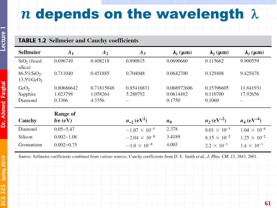
61
𝒏 depends on the wavelength
EC
E 3
25
Sprin
g 2
01
9
Dr. A
hm
ed Farghal
Lecture 1
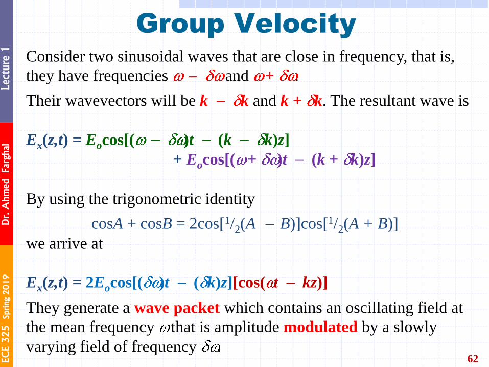
Group Velocity
62
Consider two sinusoidal waves that are close in frequency, that is,
they have frequencies and + .
Their wavevectors will be k k and k + k. The resultant wave is
Ex(z,t) = Eocos[( )t (k k)z]
+ Eocos[( + )t (k + k)z]
By using the trigonometric identity
cosA + cosB = 2cos[1/2(A B)]cos[1/2(A + B)]
we arrive at
Ex(z,t) = 2Eocos[( )t ( k)z][cos( t kz)]
They generate a wave packet which contains an oscillating field at
the mean frequency that is amplitude modulated by a slowly
varying field of frequency .
EC
E 3
25
Sprin
g 2
01
9
Dr. A
hm
ed Farghal
Lecture 1
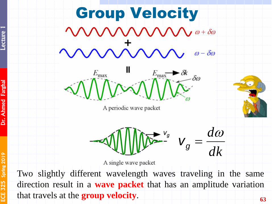
Group Velocity
63
Two slightly different wavelength waves traveling in the same
direction result in a wave packet that has an amplitude variation
that travels at the group velocity.
dk
dgv

EC
E 3
25
Sprin
g 2
01
9
Dr. A
hm
ed Farghal
Lecture 1
Adding up waves of different frequencies
64 : phase velocity : group velocity
EC
E 3
25
Sprin
g 2
01
9
Dr. A
hm
ed Farghal
Lecture 1
Group Velocity
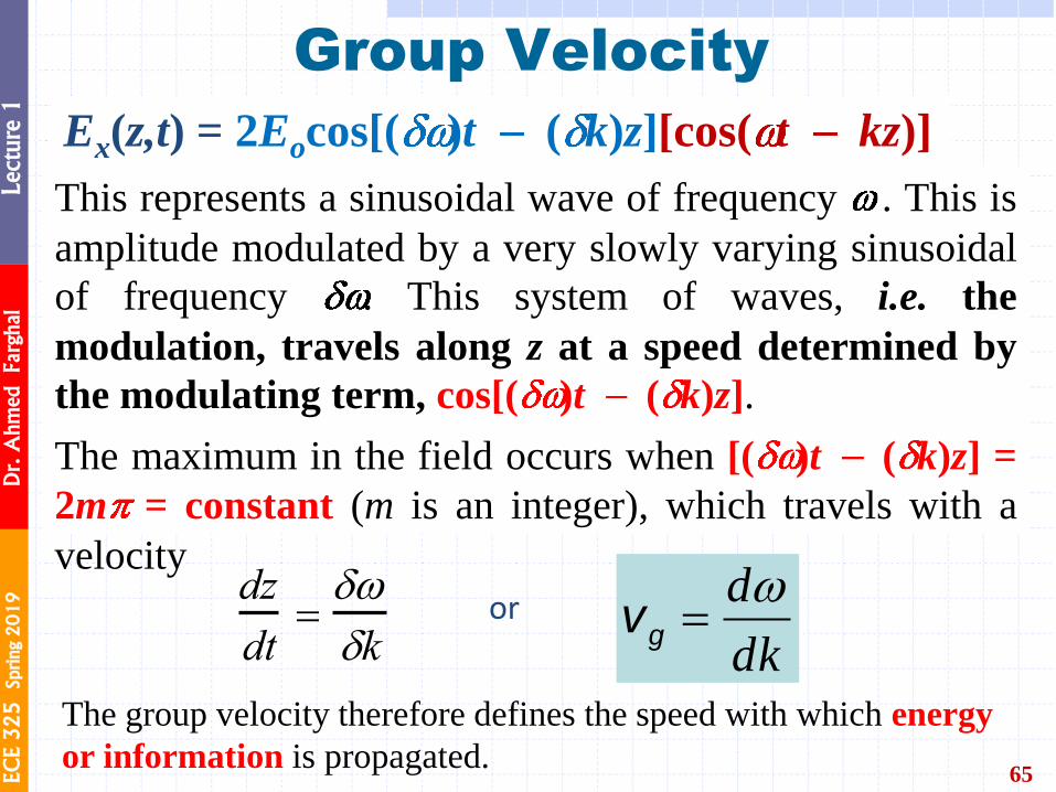
65
This represents a sinusoidal wave of frequency . This is
amplitude modulated by a very slowly varying sinusoidal
of frequency . This system of waves, i.e. the
modulation, travels along z at a speed determined by
the modulating term, cos[( )t ( k)z].
The maximum in the field occurs when [( )t ( k)z] =
2m = constant (m is an integer), which travels with a
velocity dz
dt
kor
dk
dgv
The group velocity therefore defines the speed with which energy
or information is propagated.
Ex(z,t) = 2Eocos[( )t ( k)z][cos( t kz)]
EC
E 3
25
Sprin
g 2
01
9
Dr. A
hm
ed Farghal
Lecture 1
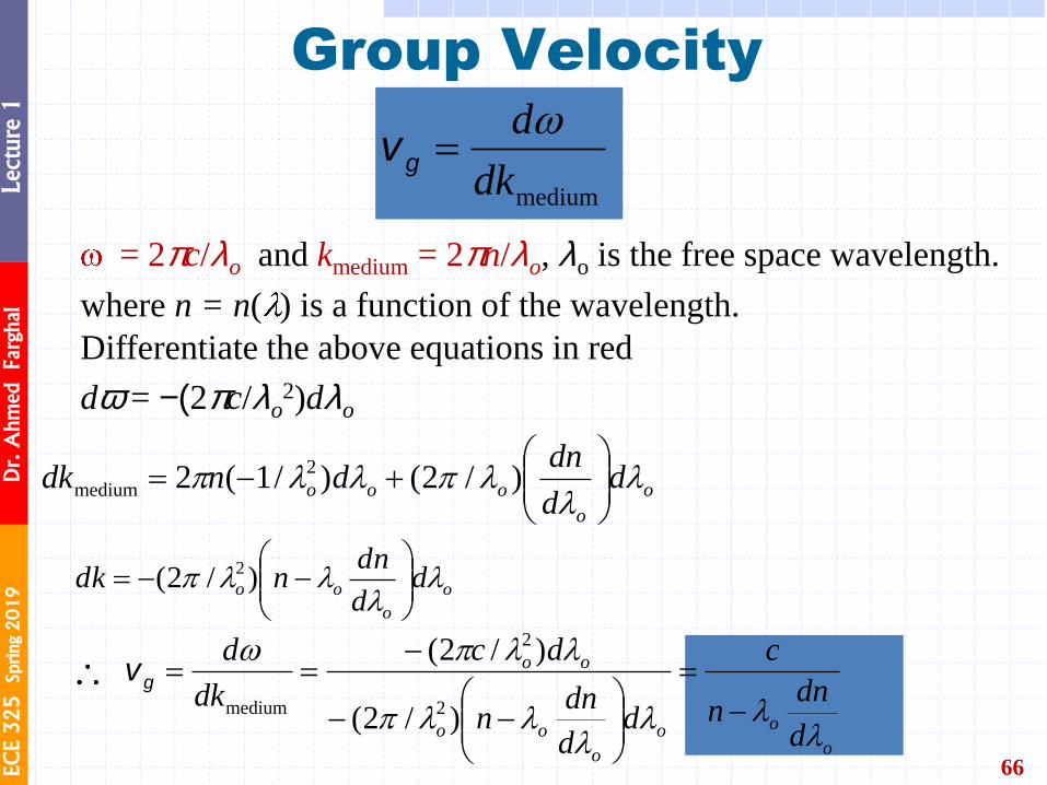
= 2pc/lo and kmedium = 2pn/lo, lo is the free space wavelength.
where n = n( ) is a function of the wavelength.
Differentiate the above equations in red
dw = -(2pc/lo2)dlo
Group Velocity
66
o
o
ooo dd
dndndk
)/2()/1(2 2
medium
mediumdk
dgv
o
o
oo dd
dnndk
)/2( 2
o
oo
o
oo
oo
d
dnn
c
dd
dnn
dc
dk
d
)/2(
)/2(
2
2
medium
gv
EC
E 3
25
Sprin
g 2
01
9
Dr. A
hm
ed Farghal
Lecture 1
Group Velocity and Group Index
67
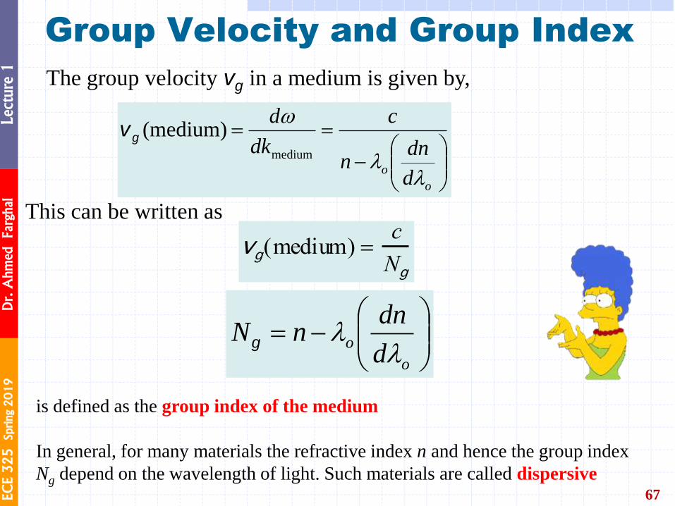
The group velocity vg in a medium is given by,
o
od
dnn
c
dk
d
medium
(medium)gv
This can be written as
vg(medium)
c
Ng
o
od
dnnN
g
is defined as the group index of the medium
In general, for many materials the refractive index n and hence the group index
Ng depend on the wavelength of light. Such materials are called dispersive

EC
E 3
25
Sprin
g 2
01
9
Dr. A
hm
ed Farghal
Lecture 1
Refractive Index and Group Index
68
Refractive index n and the group index Ng of pure SiO2 (silica) glass as a function of
wavelength.

EC
E 3
25
Sprin
g 2
01
9
Dr. A
hm
ed Farghal
Lecture 1
Light and Photons
69
However, the development of modern physics (and especially the
work of Planck and Einstein) led to the photon view of light.
𝑬ph = 𝒉𝒗 = 𝒉𝒄/𝝀 Photon energy
= wavelength
ℎ = Planck’s constant (6.63 x 10⁻³⁴ J.s)
𝑐 = speed of light (3x10⁸ m/s)
EC
E 3
25
Sprin
g 2
01
9
Dr. A
hm
ed Farghal
Lecture 1
70 From Principles of Electronic Materials and Devices, Fourth Edition, S.O. Kasap (© McGraw-Hill Education, 2018)
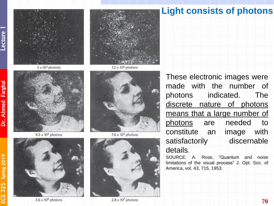
These electronic images were
made with the number of
photons indicated. The
discrete nature of photons
means that a large number of
photons are needed to
constitute an image with
satisfactorily discernable
details. SOURCE: A. Rose, “Quantum and noise
limitations of the visual process” J. Opt. Soc. of
America, vol. 43, 715, 1953.
Light consists of photons
EC
E 3
25
Sprin
g 2
01
9
Dr. A
hm
ed Farghal
Lecture 1
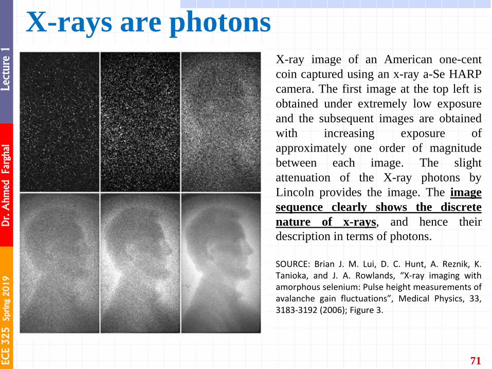
71
X-ray image of an American one-cent
coin captured using an x-ray a-Se HARP
camera. The first image at the top left is
obtained under extremely low exposure
and the subsequent images are obtained
with increasing exposure of
approximately one order of magnitude
between each image. The slight
attenuation of the X-ray photons by
Lincoln provides the image. The image
sequence clearly shows the discrete
nature of x-rays, and hence their
description in terms of photons. SOURCE: Brian J. M. Lui, D. C. Hunt, A. Reznik, K. Tanioka, and J. A. Rowlands, “X-ray imaging with amorphous selenium: Pulse height measurements of avalanche gain fluctuations”, Medical Physics, 33, 3183-3192 (2006); Figure 3.
X-rays are photons
From Principles of Electronic Materials and Devices, Fourth Edition, S.O. Kasap (© McGraw-Hill Education, 2018)

EC
E 3
25
Sprin
g 2
01
9
Dr. A
hm
ed Farghal
Lecture 1
Light and Photons
72
𝑬ph = 𝒉𝒗 = 𝒉𝒄/𝝀 and p = h/l
Intuitive visualization of light consisting
of a stream of photons
Photon flux density
= wavelength h = Planck’s constant (6.63 x 10⁻³⁴ J.s) c = speed of light (3x10⁸ m/s) p = Momentum
Light Intensity (Irradiance): the amount of energy
flowing through a unit area per unit time
Δ𝑁ph is the net number of photons crossing an
area 𝐴 in time Δ𝑡.
EC
E 3
25
Sprin
g 2
01
9
Dr. A
hm
ed Farghal
Lecture 1
Example
73
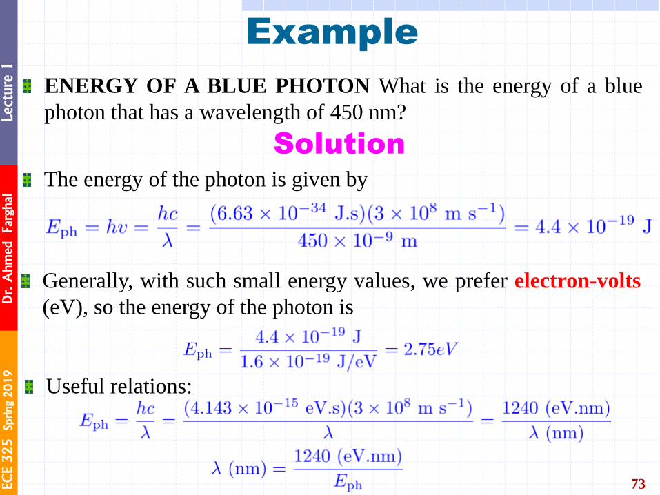
ENERGY OF A BLUE PHOTON What is the energy of a blue
photon that has a wavelength of 450 nm?
Solution The energy of the photon is given by
Generally, with such small energy values, we prefer electron-volts
(eV), so the energy of the photon is
Useful relations:

EC
E 3
25
Sprin
g 2
01
9
Dr. A
hm
ed Farghal
Lecture 1
74
Thank you