lecture (10) flow and temperature sensors
TRANSCRIPT
AMSS-MSc Prof. Kasim Al-Aubidy 1
Lecture (10)
Flow and Temperature
Sensors Prof. Kasim M. Al-Aubidy
Philadelphia University-Jordan
AMSS-MSc Prof. Kasim Al-Aubidy 2
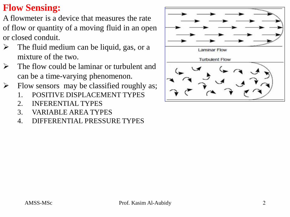
Flow Sensing: A flowmeter is a device that measures the rate
of flow or quantity of a moving fluid in an open
or closed conduit.
The fluid medium can be liquid, gas, or a
mixture of the two.
The flow could be laminar or turbulent and
can be a time-varying phenomenon.
Flow sensors may be classified roughly as; 1. POSITIVE DISPLACEMENT TYPES
2. INFERENTIAL TYPES
3. VARIABLE AREA TYPES
4. DIFFERENTIAL PRESSURE TYPES
AMSS-MSc Prof. Kasim Al-Aubidy 3
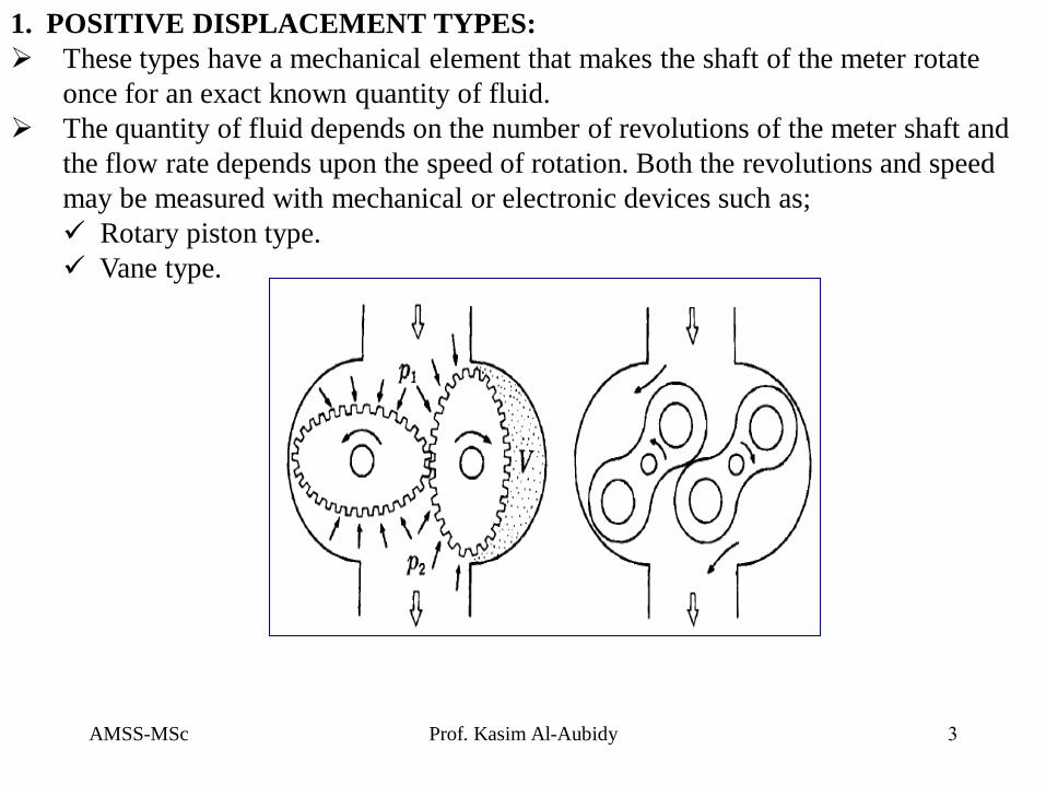
1. POSITIVE DISPLACEMENT TYPES:
These types have a mechanical element that makes the shaft of the meter rotate
once for an exact known quantity of fluid.
The quantity of fluid depends on the number of revolutions of the meter shaft and
the flow rate depends upon the speed of rotation. Both the revolutions and speed
may be measured with mechanical or electronic devices such as;
Rotary piston type.
Vane type.
AMSS-MSc Prof. Kasim Al-Aubidy 4
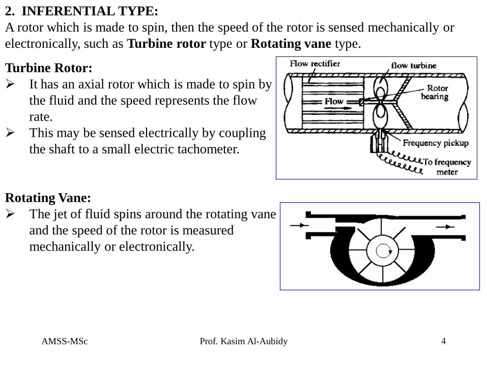
2. INFERENTIAL TYPE:
A rotor which is made to spin, then the speed of the rotor is sensed mechanically or
electronically, such as Turbine rotor type or Rotating vane type.
Turbine Rotor:
It has an axial rotor which is made to spin by
the fluid and the speed represents the flow
rate.
This may be sensed electrically by coupling
the shaft to a small electric tachometer.
Rotating Vane:
The jet of fluid spins around the rotating vane
and the speed of the rotor is measured
mechanically or electronically.
AMSS-MSc Prof. Kasim Al-Aubidy 5
Advantages and Disadvantages of the turbine meters
Advantages
The turbine meter is easy to install and maintain.
Bi-directional
Have fast response
Compact and light weights
Disadvantages
They generally are not available for steam measurement (since condensate does not
lubricate well.
They are sensitive to dirt and cannot be used for highly viscous fluids.
Flashing or slugs of vapour or gas in the liquid produce blade wear and excessive
bearing friction that can result in poor performance and possible turbine damage.
They are sensitive to the velocity profile to the presence of swirls at the inlet; they
require a uniform velocity profile (i.e. pipe straightness may have to be used).
Turbine meters have moving parts that are sensitive to wear and can be damaged by
over speeding. To prevent sudden hydraulic impact, the flow should increase
gradually into the line.
When installed, bypass piping may be required for maintenance.
The transmission cable must be protected to avoid the effect of electrical noise.
AMSS-MSc Prof. Kasim Al-Aubidy 6
3. VARIABLE AREA TYPES:
Variable area flowmeters are simple and versatile devices that operate at a relatively
constant pressure drop and measure the flow of liquids, gases, and steam. There are two
main types of this meter; the float type, and the tapered plug type.
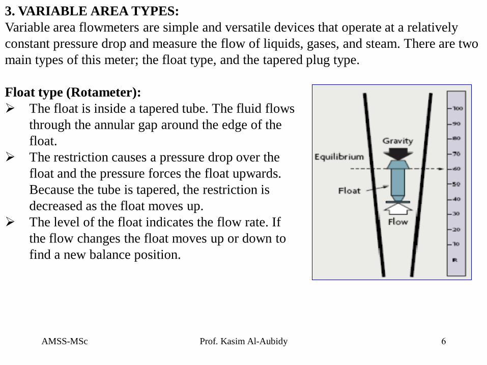
Float type (Rotameter):
The float is inside a tapered tube. The fluid flows
through the annular gap around the edge of the
float.
The restriction causes a pressure drop over the
float and the pressure forces the float upwards.
Because the tube is tapered, the restriction is
decreased as the float moves up.
The level of the float indicates the flow rate. If
the flow changes the float moves up or down to
find a new balance position.
AMSS-MSc Prof. Kasim Al-Aubidy 7
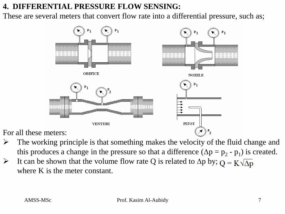
4. DIFFERENTIAL PRESSURE FLOW SENSING:
These are several meters that convert flow rate into a differential pressure, such as;
For all these meters:
The working principle is that something makes the velocity of the fluid change and
this produces a change in the pressure so that a difference (p = p2 - p1) is created.
It can be shown that the volume flow rate Q is related to p by;
where K is the meter constant.
AMSS-MSc Prof. Kasim Al-Aubidy 8
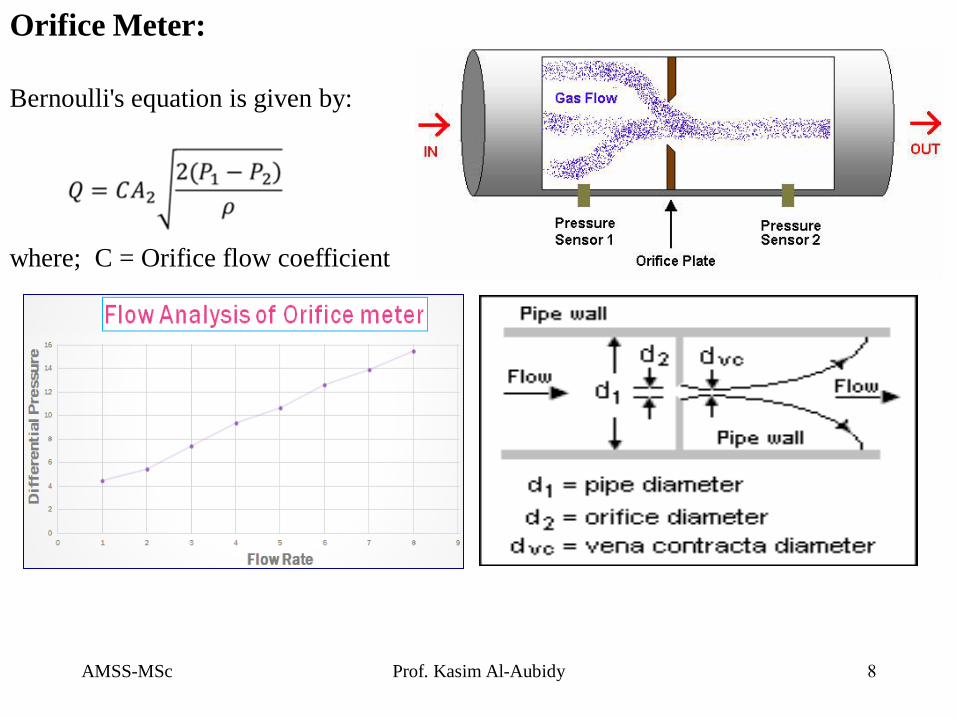
Orifice Meter:
Bernoulli's equation is given by:
where; C = Orifice flow coefficient

AMSS-MSc Prof. Kasim Al-Aubidy 9
Advantages and Disadvantages of Orifice flowmeters
Advantages:
They are easy to install.
One differential pressure transmitter applies for any pipe size.
Many DP sensing materials are available to meet process requirements.
Orifice plates have no moving parts and have been researched extensively;
therefore, application data well documented (compared to other primary differential
pressure elements).
Disadvantages:
The process fluid is in the impulse lines to the differential transmitter may freeze or
block.
Their accuracy is affected by changes in density, viscosity, and temperature.
They require frequent calibration
AMSS-MSc Prof. Kasim Al-Aubidy 10
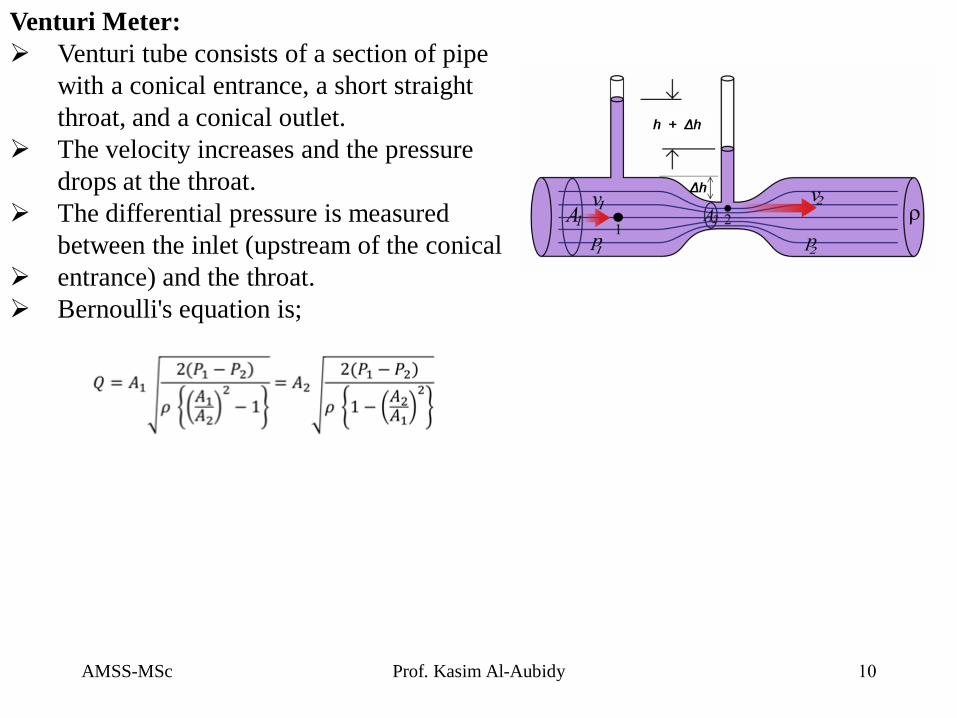
Venturi Meter:
Venturi tube consists of a section of pipe
with a conical entrance, a short straight
throat, and a conical outlet.
The velocity increases and the pressure
drops at the throat.
The differential pressure is measured
between the inlet (upstream of the conical
entrance) and the throat.
Bernoulli's equation is;
AMSS-MSc Prof. Kasim Al-Aubidy 11
Advantages and Disadvantages of VENTURI TUBES
Advantage
It can handle low-pressure applications
It can measure 25 to 50% more flow than a comparable orifice plate
It is less susceptible to wear and corrosion compared to orifice plates
It is suitable for measurement in very large water pipes and very large air/Gas
ducts.
Provides better performance than the orifice plate when there are solids in
Suspension.
Disadvantage
It is the most expensive among the differential pressure meters
It is big and heavy for large sizes
Its has considerable length
AMSS-MSc Prof. Kasim Al-Aubidy 12
ELECTRONIC FLOWMETERS:
Electronic flowmeters represent a logical grouping of flow measurement technologies.
All have no moving parts, are relatively non-intrusive, and are made possible by today's
sophisticated electronics technology.
There are three types of electronic flowmeters:
1. Magnetic flowmeters,
2. Vortex flowmeters,
3. Ultrasonic flowmeters

AMSS-MSc Prof. Kasim Al-Aubidy 13
MAGNETIC FLOWMETERS:
The magnetic flow meter design is based on Faraday’s law of magnetic induction,
which states that: "The voltage induced across a conductor as it moves at right
angles through a magnetic field proportional to the velocity of that conductor”.
If a conductor is moving perpendicular to its length through a magnetic field, it will
generate an electrical potential (E) between its two ends;
E = B x L x v where:
B = the strength of the magnetic field (induction)
L = the length of the conductor (distance of electrodes)
v = velocity of the conductor (average flow velocity)
Magmeter Flow Equation:
If a conductive fluid flows through a pipe of diameter (D) through a magnetic field
density (B) generated by the coils, the amount of voltage (E) developed across the
electrodes will be proportional to the velocity (V) of the liquid. Because the magnetic
field density and the pipe diameter are fixed values, they can be combined into a
calibration factor (K) and the equation reduces to: E= K x V
AMSS-MSc Prof. Kasim Al-Aubidy 14
Advantages and Disadvantages of Magmeter
Advantages:
Are bi-directional, have no flow obstruction, easy to re-span
Are available with DC or AC power
It can measure pulsating and corrosive flow.
It can measure multiphase; however, all components should be moving at the same speed; the
meter can measure the speed of the most conductive component.
It can install vertically or horizontally (the line must be full, however) and can be used with
fluids with conductivity greater than 200 umhos/cm.
Changes in conductivity value do not, affect the instrument performance.
Disadvantages
It's above average cost
It's large size
Its need for a minimum electrical conductivity of 5 to 20 μmhos / cm
Its accuracy is affected by slurries containing magnetic solids.
Electrical coating may cause calibration shifts
The line must be full and have no air bubbles (air and gas bubbles entrained in the liquid will
be metered as liquid, causing a measurement error).
In some applications, appropriate mechanical protection for the electrodes must be provided.
AMSS-MSc Prof. Kasim Al-Aubidy 15
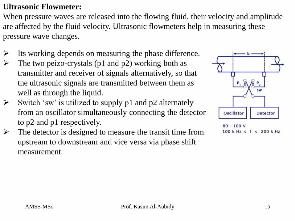
Its working depends on measuring the phase difference.
The two peizo-crystals (p1 and p2) working both as
transmitter and receiver of signals alternatively, so that
the ultrasonic signals are transmitted between them as
well as through the liquid.
Switch ‘sw’ is utilized to supply p1 and p2 alternately
from an oscillator simultaneously connecting the detector
to p2 and p1 respectively.
The detector is designed to measure the transit time from
upstream to downstream and vice versa via phase shift
measurement.
Ultrasonic Flowmeter:
When pressure waves are released into the flowing fluid, their velocity and amplitude
are affected by the fluid velocity. Ultrasonic flowmeters help in measuring these
pressure wave changes.
AMSS-MSc Prof. Kasim Al-Aubidy 16
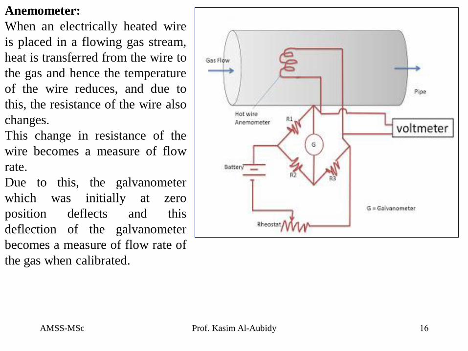
Anemometer:
When an electrically heated wire
is placed in a flowing gas stream,
heat is transferred from the wire to
the gas and hence the temperature
of the wire reduces, and due to
this, the resistance of the wire also
changes.
This change in resistance of the
wire becomes a measure of flow
rate.
Due to this, the galvanometer
which was initially at zero
position deflects and this
deflection of the galvanometer
becomes a measure of flow rate of
the gas when calibrated.
AMSS-MSc Prof. Kasim Al-Aubidy 17
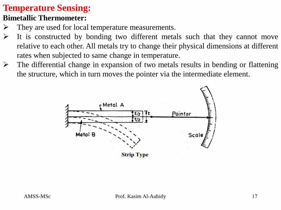
Temperature Sensing: Bimetallic Thermometer:
They are used for local temperature measurements.
It is constructed by bonding two different metals such that they cannot move
relative to each other. All metals try to change their physical dimensions at different
rates when subjected to same change in temperature.
The differential change in expansion of two metals results in bending or flattening
the structure, which in turn moves the pointer via the intermediate element.
AMSS-MSc Prof. Kasim Al-Aubidy 18
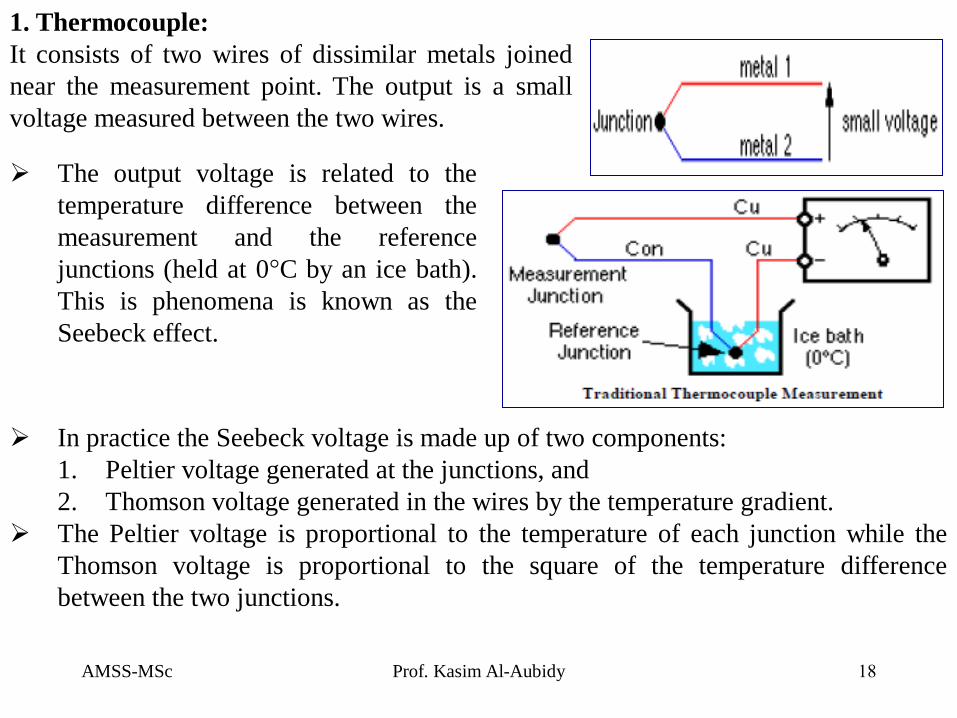
1. Thermocouple:
It consists of two wires of dissimilar metals joined
near the measurement point. The output is a small
voltage measured between the two wires.
In practice the Seebeck voltage is made up of two components:
1. Peltier voltage generated at the junctions, and
2. Thomson voltage generated in the wires by the temperature gradient.
The Peltier voltage is proportional to the temperature of each junction while the
Thomson voltage is proportional to the square of the temperature difference
between the two junctions.
The output voltage is related to the
temperature difference between the
measurement and the reference
junctions (held at 0°C by an ice bath).
This is phenomena is known as the
Seebeck effect.
AMSS-MSc Prof. Kasim Al-Aubidy 19
The advantages and disadvantages of thermocouples:
Because of their physical characteristics, thermocouples
are the preferred method of temperature measurement in
many applications. Thermocouples are wonderful sensors
to experiment with because of their robustness, wide
temperature range and unique properties.
Advantages:
They can be very rugged, are immune to shock and vibration, are useful over a wide
temperature range, are simple to manufactured, require no excitation power, there is no
self heating and they can be made very small.
Disadvantages:
Nonlinear
Low voltage output.
Reference required.
Less stable.
AMSS-MSc Prof. Kasim Al-Aubidy 20
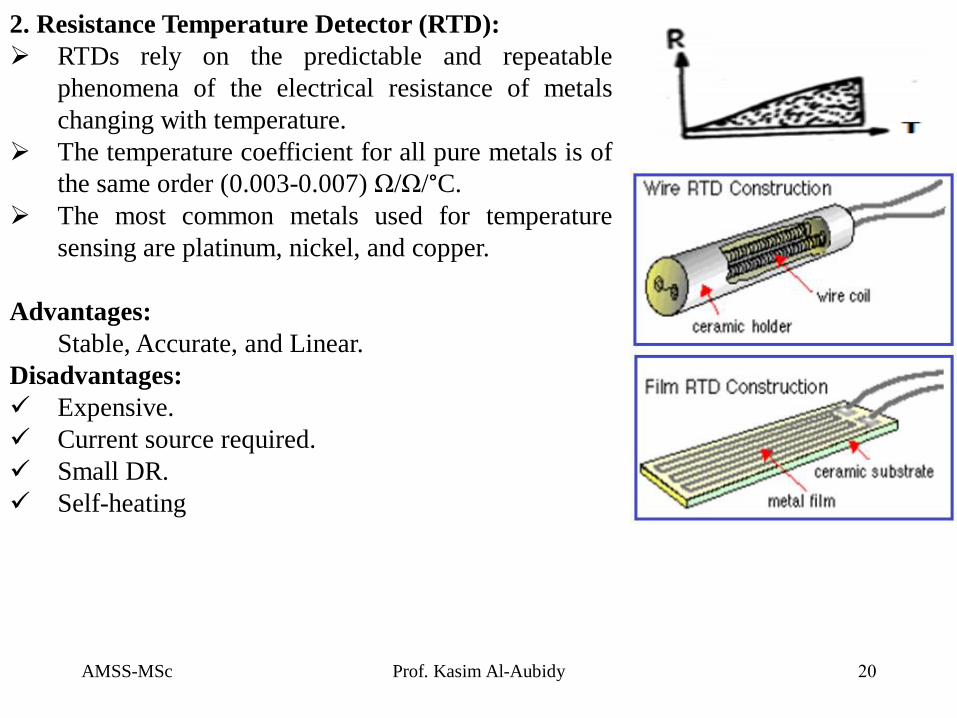
2. Resistance Temperature Detector (RTD):
RTDs rely on the predictable and repeatable
phenomena of the electrical resistance of metals
changing with temperature.
The temperature coefficient for all pure metals is of
the same order (0.003-0.007) Ω/Ω/°C.
The most common metals used for temperature
sensing are platinum, nickel, and copper.
Advantages:
Stable, Accurate, and Linear.
Disadvantages:
Expensive.
Current source required.
Small DR.
Self-heating
AMSS-MSc Prof. Kasim Al-Aubidy 21
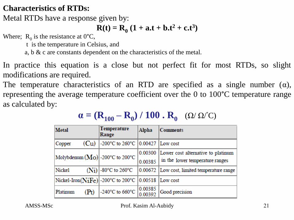
Characteristics of RTDs:
Metal RTDs have a response given by:
R(t) = R0 (1 + a.t + b.t2 + c.t3) Where; R0 is the resistance at 0°C,
t is the temperature in Celsius, and
a, b & c are constants dependent on the characteristics of the metal.
In practice this equation is a close but not perfect fit for most RTDs, so slight
modifications are required.
The temperature characteristics of an RTD are specified as a single number (α),
representing the average temperature coefficient over the 0 to 100°C temperature range
as calculated by:
α = (R100 – R0) / 100 . R0 (Ω/ Ω/°C)
AMSS-MSc Prof. Kasim Al-Aubidy 22
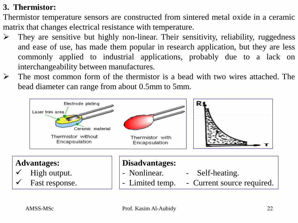
3. Thermistor:
Thermistor temperature sensors are constructed from sintered metal oxide in a ceramic
matrix that changes electrical resistance with temperature.
They are sensitive but highly non-linear. Their sensitivity, reliability, ruggedness
and ease of use, has made them popular in research application, but they are less
commonly applied to industrial applications, probably due to a lack on
interchangeability between manufactures.
The most common form of the thermistor is a bead with two wires attached. The
bead diameter can range from about 0.5mm to 5mm.
Advantages:
High output.
Fast response.
Disadvantages:
- Nonlinear. - Self-heating.
- Limited temp. - Current source required.
AMSS-MSc Prof. Kasim Al-Aubidy 23
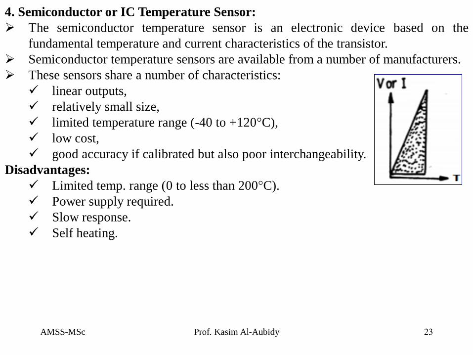
4. Semiconductor or IC Temperature Sensor:
The semiconductor temperature sensor is an electronic device based on the
fundamental temperature and current characteristics of the transistor.
Semiconductor temperature sensors are available from a number of manufacturers.
These sensors share a number of characteristics:
linear outputs,
relatively small size,
limited temperature range (-40 to +120°C),
low cost,
good accuracy if calibrated but also poor interchangeability.
Disadvantages:
Limited temp. range (0 to less than 200°C).
Power supply required.
Slow response.
Self heating.
AMSS-MSc Prof. Kasim Al-Aubidy 24
References:
1. Jacob Fraden, “Handbook of Modern Sensors; Physics, Design, and Applications”, Fourth Edition,
Springer Press 2010.
2. Kelley CT (2003) Solving nonlinear equations with Newton’s method, No. 1 Fundamentals of
Algorithms. SIAM, Philadelphia, PA
3. ISO guide to the expression of uncertainty in measurements (1993) International Organization for
Standardization, Geneva, Switzerland
4. Taylor BN, Kuyatt CE (1994) Guidelines for evaluation and expressing the uncertainty of NIST
measurement results. NIST Technical Note 1297. US Government Printing Office, Washington DC
5. Widlar RJ (1980) Working with high impedance Op Amps, AN24, Linear Application Handbook.
National Semiconductor
6. Sheingold DH (ed) (1986) Analog-Digital Conversion Handbook. 3rd ed., Prentice-Hall, Englewood
Cliffs, NJ.
7. Williams J (1990) Some techniques for direct digitization of transducer outputs, AN7, Linear Technology
Application Handbook.
8. Long DJ (1975) Occupancy detector apparatus for automotive safety system. US Patent 3,898,472, 5 Aug
9. Park YE, Wise KD (1983) An MOS switched-capacitor readout amplifier for capacitive pressure sensors.
IEEE Custom IC Conf 380–384.
10. Ryser P, Pfister G (1991) Optical fire and security technology: sensor principles and detection
intelligence. In: Transducers’91. International conference on solid-state sensors and actuators. Digest of
technical papers, pp 579–583, IEEE.
11. Consolidated Electrodynamics, Bulletin 4202B/1167 on Type 4-202 Strain Gauge Accelerometer.
12. http://www.instrumentationtoday.com/