lecture 12- polling vs interrupt
TRANSCRIPT

Lecture 12 Slide 1PYKC 3 Feb 2020 DE2.3 – Electronics 2
Lecture 12
Motor Drive, Polling and Interrupt
Prof Peter YK Cheung
Dyson School of Design Engineering
URL: www.ee.ic.ac.uk/pcheung/teaching/DE2_EE/E-mail: [email protected]

Lecture 12 Slide 2PYKC 3 Feb 2020 DE2.3 – Electronics 2
Driving a DC Motor – H-Bridge
! The DC motor needs four transistors to control its speed and direction.
! In Lab 5, we used the TB6612 chip to drive the motor with four transistors.
! The combination of transistors is called an H-Bridge, due to the obvious shape. (See diagram.)
! Transistors are switched diagonally to allow DC current to flow in the motor in either direction.
! The transistors can be Pulse Width Modulated to reduce the average voltage at the motor, useful for controlling current and speed.
1
10
0
0
10
1
Motor
Motor

Lecture 12 Slide 3PYKC 3 Feb 2020 DE2.3 – Electronics 2
Pybench Board and its components

Lecture 12 Slide 4PYKC 3 Feb 2020 DE2.3 – Electronics 2
Check before you connect
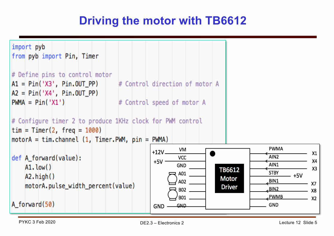
Lecture 12 Slide 5PYKC 3 Feb 2020 DE2.3 – Electronics 2
Driving the motor with TB6612

Lecture 12 Slide 6PYKC 3 Feb 2020 DE2.3 – Electronics 2
Controlling the speed with potentiometer

Lecture 12 Slide 7PYKC 3 Feb 2020 DE2.3 – Electronics 2
Measuring Motor speed with Hall Effect Sensors
motorA - Y4motorB - Y6
motorA –Y6motorB – Y7
• Circular magnet has 13 pole pairs• The gearbox of the motor has a 1:30
gear ratio• How many pulses are produced for
each revolution of the motor?• Speed of motor (in rps) can be
measured by counting the number of pulses in a given time window (say 100msec)

Lecture 12 Slide 8PYKC 3 Feb 2020 DE2.3 – Electronics 2
Pseudo code to measure speed by polling
• Initialize variables to zero: motor_speed, sensor_state, pulse_count• Repeat forever:
Mark current time (as tic)If sensor has gone from low to high (rising edge)
increment pulse_countUpdate sensor_state by reading hall effort sensor valueIf elapse_time >= 100ms
motor_speed = pulse_countreset pulse_countdisplay speed on OLED as motor_speed/39
Discuss: what is the limitation of polling?

Lecture 12 Slide 9PYKC 3 Feb 2020 DE2.3 – Electronics 2
Measure motor speed by polling
! Polling means checking for some event in a loop, then do something
! Here we check sensor signal of motor A changing from low to high in the polling loop
! When this occurs, increment a counter A_count
! We also check elapsed time = 100msec in polling loop (tic-toc)
! If time out, save count as speed measurement A_speed, and reset counter

Lecture 12 Slide 10PYKC 3 Feb 2020 DE2.3 – Electronics 2
Interrupt occurs while in instruction 4
1. Save the state of program2. Jump to ISR3. Stop further interrupts4. When finish return
! Hardware method to detect event (e.g. rising edge on a pin), generate interrupt
! Processor forced to do something else – defined in the Interrupt Service Routine (ISR)
! Return when finished
Lab 4: The idea of interrupt

Lecture 12 Slide 11PYKC 3 Feb 2020 DE2.3 – Electronics 2
Lab 4: Interrupt Service Routines
! Need to detect and handle two types of events:1. Rising edge on Hall effect sensor signal on Y42. 100ms elapsed time on a Timer
! Need two ISRs for these two interrupt events! Need to provide a dummy variable as shown here

Lecture 12 Slide 12PYKC 3 Feb 2020 DE2.3 – Electronics 2
Lab 4: setting up the interrupts
! Allocate some buffer space to handle errors! Specify Pin Y4 as source of interrupt, rising edge! Define timer 4 as a 100msec period timer (10Hz)! timer.callback (ISR) - tell timer to generate an interrupt at end of period, and
execute ISRSpecify ISR for pin rising edgeSpecify ISR for timer time-out

Lecture 12 Slide 13PYKC 3 Feb 2020 DE2.3 – Electronics 2
Lab 4 – Interrupt MAGIC
! Program loop does not deal with motor sensor edge, not 100msec elapse time! A_speed will always contain instantaneous speed count
Wheel rotating at 1 rpswill produce 39 rising edges in 0.1 sec

Lecture 12 Slide 14PYKC 3 Feb 2020 DE2.3 – Electronics 2
Pin Assignments for Pybench