lecture 12 umts universal mobile telecom. systemilenia/course/12-umts.pdfumts stands for universal...
TRANSCRIPT

Lecture 12Lecture 12
UMTS UMTS
I. Tinnirello
UMTS UMTS
Universal Mobile Telecom. SystemUniversal Mobile Telecom. System

What is UMTS?What is UMTS?
� UMTS stands for Universal Mobile Telecommunication
System
� It is a part of the ITU “IMT-2000” vision of a global family of
3G mobile communication systems
� In 1998, at the end of the proposal submission phase, 17
proposals have been presented and accepted
�main differences due to existing 2G networks
I. Tinnirello
� UMTS is the European proposal
� 3GPP group founded to coordinate various proposals and
defining a common solution
� Compatibility guaranteed by multi-standard multi-mode
or reconfigurable terminals

IMTIMT--2000 Variants2000 Variants
�IMT-2000 includes a family of terrestrial 3G systems based on the following radio interfaces
�IMT-DS (Direct Spread)�UMTS FDD, FOMA (standardized by 3GPP)
�IMT-MC (Multi Carrier)
I. Tinnirello
�IMT-MC (Multi Carrier)�CDMA 2000, evolution of IS-95 (standardized by 3GPP)
�IMT-TC (Time Code)�UMTS TDD and TD-SCDMA (standardized by 3GPP)

UMTS: Initial GoalsUMTS: Initial Goals
1. UMTS will be compatible with 2G systems
2. UMTS will use the same frequency spectrum everywhere in the world
3. UMTS will be a global system
I. Tinnirello
3. UMTS will be a global system
4. UMTS will provide multimedia and internet services
5. UMTS will provide QoS guarantees

IMTIMT--2000 Features 2000 Features
� Higher data rate through the Air Interface
� At least 144 kb/s (preferably 384 kb/s)
�For high mobility (speed up to 250 km/h) subscribers
�In a wide area coverage (rural outdoor): larger than 1 km
� At least 384 kb/s (preferably 512 kb/s)
�For limited mobility (speed up to 120 km/h) subscribers
�In micro and macro cellular environments
I. Tinnirello
�In micro and macro cellular environments (urban/suburban area): max 1 km
� 2 Mb/s
�For low mobility (speed up to 10 km/h) subscribers
�In local coverage areas (indoor and low range outdoor): max 500 m

Universal ScenarioUniversal Scenario
I. Tinnirello

UMTS Network ArchitectureUMTS Network Architecture
I. Tinnirello

UMTS Releases (1)UMTS Releases (1)
� Release 99 – Major RAN release – March 2000
� New radio interface WCDMA
� New RAN architecture
� New CN-AC interface
�Open Service architecture for services
�GSM-UMTS Internetworking
� Release 4 – Minor release – March 2001
I. Tinnirello
� Release 4 – Minor release – March 2001
� UTRAN access with QoS enhancements
� CS domain evolution, MSC servers and MGWs, based on IP protocols
� IP Header Compression
� Location services enhancements, MMS, WAP..
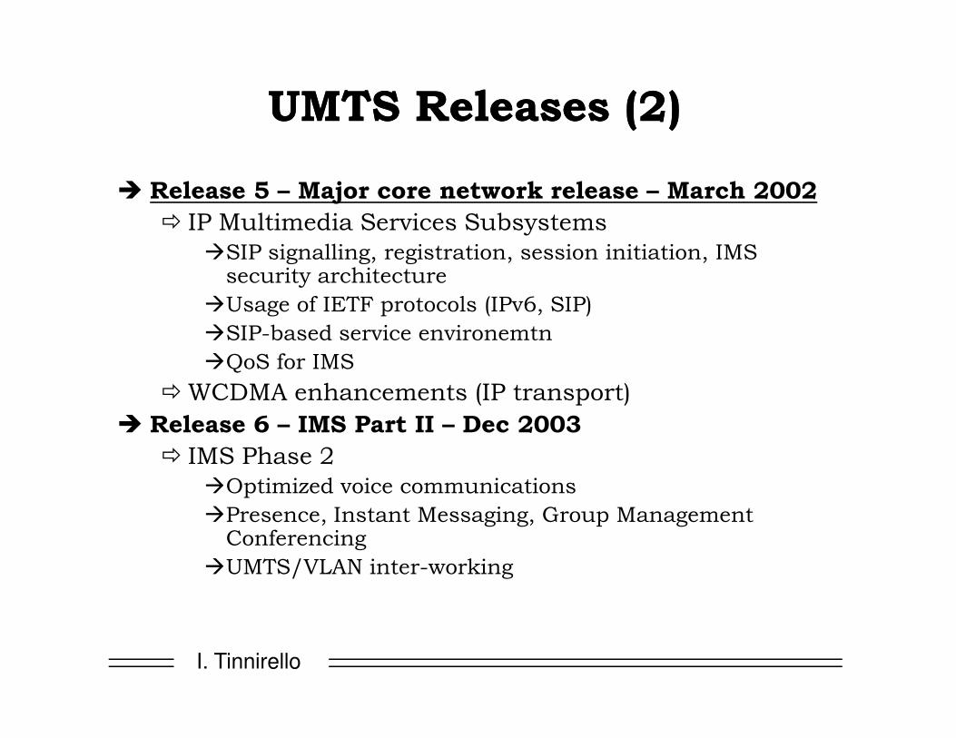
UMTS Releases (2)UMTS Releases (2)
� Release 5 – Major core network release – March 2002
� IP Multimedia Services Subsystems
�SIP signalling, registration, session initiation, IMS security architecture
�Usage of IETF protocols (IPv6, SIP)
�SIP-based service environemtn
�QoS for IMS
I. Tinnirello
�QoS for IMS
�WCDMA enhancements (IP transport)
� Release 6 – IMS Part II – Dec 2003
� IMS Phase 2
�Optimized voice communications
�Presence, Instant Messaging, Group Management Conferencing
�UMTS/VLAN inter-working

GSM/GPRS core networkRadio access network
BSS
PS
TN
, ISD
N
BTS
BSC
MSC
VLR
GMSC
HLRMS
GSM/GPRS Network ArchitectureGSM/GPRS Network Architecture
I. Tinnirello
database
IP Backbone
Internet
PS
TN
, ISD
N
BTS
SGSNAuC
EIR
GGSN
PCU

Core network (GSM/GPRS-based)Radio access network
UTRAN
UE
Iu CS
IurUu
PS
TN
BS
RNC MSC
VLR
GMSC
HLR
AuC
Iub
3G Rel.’99 N3G Rel.’99 Networketwork ArchitectureArchitecture
I. Tinnirello
Iub
GnIu PS
database
IP Backbone
Internet
BS
RNC SGSNAuC
EIR
GGSN

3G in long term (1)3G in long term (1)
�UMTS capabilities must be progressively increased by the addition of new technologies�HSPDA (High Speed Downlink Packet Access) – It is a packet-based data service in WCDMA downlink with data transmission up to 8-10 Mbps (and 20 Mbps for MIMO systems) over a 5 MHz bandwidth
�Release 5: specifications focus on HSDPA to
I. Tinnirello
�Release 5: specifications focus on HSDPA to provide data rates up to approximately 10 Mbps to support packet-based multimedia services
�MIMO Systems are the work item in release 6 specifications, which will support even higher data transmission rates up to 20 Mbps. HSDPA is evolved from and backward compatible with release 99.

3G in long term (2)3G in long term (2)
� Reconfigurable terminals – UMTS terminals will have to exist in a world of multiple standards. In order to provide universal coverage, seamless roaming and non standardized services, they will be in the form of a toolbox whereby the key parameters can be selected or negotiated to mach the requirements of the local radio channel
� In order to adapt to different standards, terminals will enable network operators to distribute new
I. Tinnirello
enable network operators to distribute new communications software via download over the air interface (this process will be invisible to the user)
� Capabilities of the terminal can be modified over time through a software download over the air, at the user’s request or automatically by the network

IMT 2000 Frequency PlanIMT 2000 Frequency Plan
MSS: Mobile
Satellite System
TDD more efficient for
asymmetric services
I. Tinnirello
Satellite System

�Conversational: real-time services withconstraints on maximum packet delay (telephony, videoconference, etc.)
�Streaming: information retrieving services withless strict delay constraints (e.g., audio/video)
�Interactive: real-time data services, with delay
QoSQoS ClassesClasses and and ServicesServices
I. Tinnirello
�Interactive: real-time data services, with delayconstraints on the RTT and reliability constraints
�Background: best-effort traffic (SMS, e-mail, ...) with reliability constraints
+ evolution towards an open plaform for furtherapplication definitions (as in the Internet case)

Protocol Structures (1)Protocol Structures (1)
�From the protocol structure point of view the 3G
network can be divided into two strata: access
stratum and non-access stratum
�Stratum refers to the way of grouping protocols
related to one aspect of the services provided by
one or several domains (3GPP specifications)
I. Tinnirello
one or several domains (3GPP specifications)
�The access stratum contains the protocols
handling activities between UE and access network
�The non-access stratum contains protocols
handling activities between UE and Core Network

Protocol Structures (2)Protocol Structures (2)
I. Tinnirello

With respect to GSM & GPRS…With respect to GSM & GPRS…
�UMTS defines a new Radio Access Network
�It adds the IMS
I. Tinnirello

UMTS Radio InterfaceUMTS Radio Interface
(UTRAN)(UTRAN)
I. Tinnirello
(UTRAN)(UTRAN)
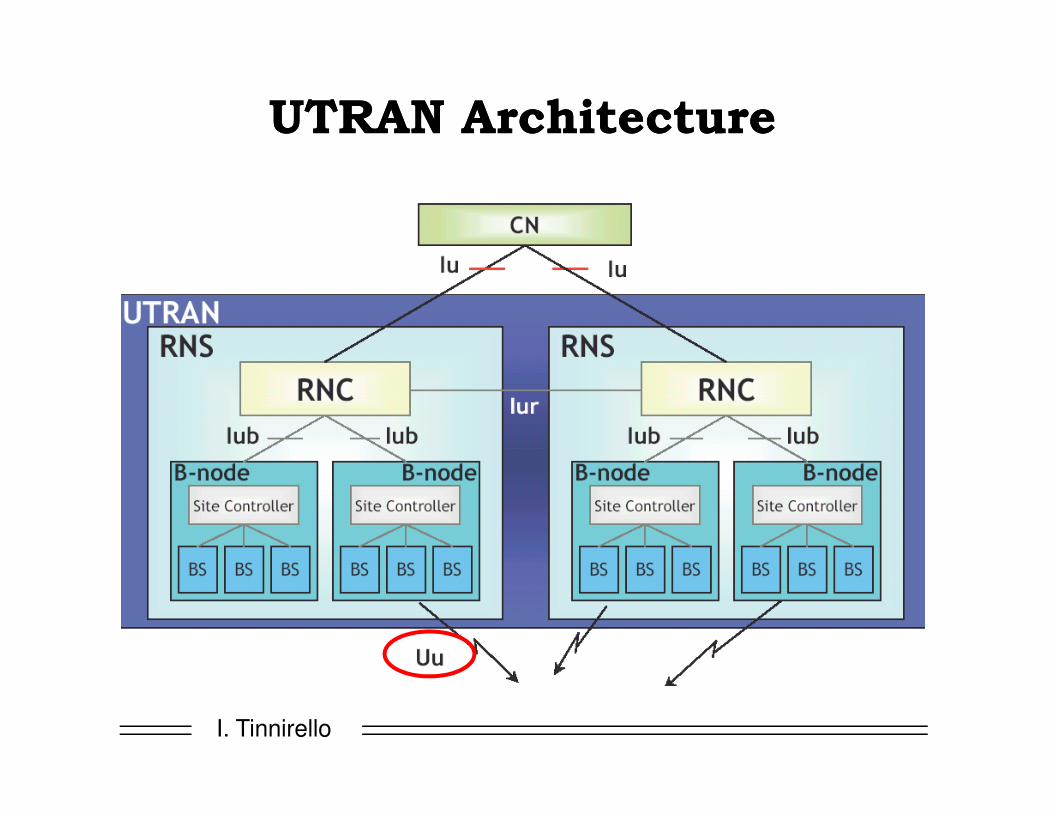
UTRAN ArchitectureUTRAN Architecture
I. Tinnirello

UTRAN (1)UTRAN (1)
� It is able to handle 2 types of calls/connections
� Circuit switched
� Packet switched
� The UTRAN consists of a set of Radio Network Subsystems (RNSs) connected to the CN through the Iu interface
� a RNS consists of a Radio Network Controller (RNC) and one or more Node Bs
I. Tinnirello
and one or more Node Bs�a Node B is connected to the RNC through the Iub interface and it can support FDD mode, TDD mode or dualmode operation
� RNCs of the Radio Network Subsystems can be interconnected together through the Iur interface to manage mobility inside UTRAN when MS moves from one RNS to another one (when the interface Iur is not implemented, CN is involved in HO procedures)

UTRAN (2)UTRAN (2)
�Transport technology on Iu, Iub and Iur
interfaces is ATM, Asynchronous Transfer Mode
�Cell transmission over physical layer (SDH,
PCM etc)
�Fast packet switching
I. Tinnirello
�Virtual circuit/virtual path based switching
�Connection oriented technique

ATM TransmissionATM Transmission
�The WCDMA Air interface provides an efficient and flexible radio access bearer for UMTS users
�This means that the transmission network connecting the radio access devices together must be flexible too
�E1, the synchronous, timeslot-based 2 Mbit/s
I. Tinnirello
�E1, the synchronous, timeslot-based 2 Mbit/s transmission technology used by GSM could not provide the flexibility required
�An alternative transmission technology was chosen: ATM or Asynchronous Transfer Mode

GSM over E1GSM over E1
I. Tinnirello

ATM transmissionATM transmission
� ATM does not base its transmission on timeslots,
instead user information is carried across the
network in containers called cells
� Each cell is a fixed length of 53 octets (bytes) and
consists of
� a 48 octet payload that carries user data
I. Tinnirello
� a 5 octet header that contains user identification

ATM transmission (2)ATM transmission (2)
� Each user connection is allocated a unique label to
identify their cells and ATM network elements are
given instructions detailing where each customer‘s
celles should be delivered
� If the user sends some information, it is placed in the
payload of a cell and their label is added to the
header; the network uses the label to determine the
I. Tinnirello
header; the network uses the label to determine the
cell’s specified delivery destination
� Users are not required to provide a fixed amount of
data at regular intervals, as with 2 Mbit/s systems.
Instead, users only fill cells when they have:
bandwidth on demand

Circuit Switching (i)Circuit Switching (i)
switch switch
TDM
TDM link
I. Tinnirello
time#1 #2 … #8 #1 #2 … #8
frame
TDM
slotctrl
…
Time Division Multiplexing

Circuit Switching (ii)Circuit Switching (ii)
switch switch
#1 #2 … #8
IN_A
OUT_A
OUT_B
IN_BIN_A
#1 #2 … #8
OUT_A
I. Tinnirello
#1 #2 … #8
#1 #2 … #8
IN_B
#1 #2 … #8
#1 #2 … #8
OUT_B
SWITCHING
TABLE
A,1 B,2A,3 B,4A,4 A,2B,1 B,1B,4 B,3B,6 A,1B,7 B,5
IN OUT
Table setup: upon signalling

Statistical MultiplexingStatistical Multiplexingthe advantage of packet switchingthe advantage of packet switching
#1 #2
Circuit switching:
Each slot uniquely
Assigned to a flow #3 #4 #1 #2 #3 #4
Full capacity does not imply full utilization!!
idle idle idle idle
I. Tinnirello
Packet switching:
Each packet grabs
The first slot available
More flows than nominal capacity may be admitted!!

Packet switching overheadPacket switching overhead
� Header: contains lots of information
� Routing, protocol-specific info, etc
� Minimum: 28 bytes; in practice much more than 40 bytes
�Overhead for every considered protocol: (for voice: 20 bytes IP, 8
packetheader
I. Tinnirello
�Overhead for every considered protocol: (for voice: 20 bytes IP, 8 bytes UDP, 12 bytes RTP)
� Question: how to minimize header while maintaining packet switching?
� Solution: label switching (virtual circuit)
� ATM
� MPLS

Label Switching (virtual circuit)Label Switching (virtual circuit)
switch switchIN_A
OUT_A
OUT_B
IN_BIN_A OUT_A21 2210 61 13
I. Tinnirello
IN_B OUT_B14 16 19 33
LABEL
SWITCHING
TABLE
10 A14 B16 B19 B21 B22 B33 A
Label-IN OUT61611287103213
Label-OUT
61 12 10 32 87
Condition: labels unique @ input
Advantage: labels very small!!
(ATM technology overhead:
only 5 bytes for all info!)
KEY advantage: no reserved phy slots!
(asynchronous transfer mode vs synchronous)

ATM transmission (3)ATM transmission (3)
I. Tinnirello

UMTS ProtocolsUMTS Protocols
Different protocol stacks for user and control plane
� User plane (for transport of user data):
� Circuit switched domain: data within ”bit pipes”
� Packet switched domain: protocols for implementingvarious QoS or traffic engineering mechanisms
I. Tinnirello
� Control plane (for signalling):
� Circuit switched domain: SS7 based (in core network)
� Packet switched domain: IP based (in core network)
� Radio access network: UTRAN protocols

Data streams
RLC
MAC
Uu Iu Gn
RLC
MAC
TDM
Frame Protocol (FP)
AAL2 AAL2 TDM
UU--Plane Protocol Stack (CS Domain)Plane Protocol Stack (CS Domain)
I. Tinnirello
MAC
Phys.
UE UTRAN 3G MSC GMSC
MAC
Phys.
WCDMA
AAL2
ATM
Phys.
AAL2
ATM
Phys.

PDCP
RLC
GTP
UDP
IP
GTP
UDP
IP
IP IP
GTP
UDP
PDCP
RLC
MAC MACAAL5 AAL5
IP
L2
GTP
UDP
IP
L2
Uu Iu Gn
UU--Plane Protocol Stack (PS Domain)Plane Protocol Stack (PS Domain)
I. Tinnirello
MAC
Phys.
MAC
Phys.
ATM
Phys.
ATM
Phys.
L2
L1
L2
L1
UE UTRAN SGSN GGSN
WCDMA

RRC
Signalling
radio bearers
(User plane)
radio bearers
e.g. MM, CC, SM
transparent to UTRAN
PDCPL3
UuUu interface protocolsinterface protocols
I. Tinnirello
PHY
MAC
RLC
Logical channels
Transport channels
L2
L1

Main tasks of Main tasks of UuUu interface protocolsinterface protocols
� MAC (Medium Access Control)
� Mapping between logical and transport channels
� Segmentation of data into transport blocks
� RLC(Radio Link Control)
� Segmentation and reassembly
� Link control (flow and error control)
I. Tinnirello
� Link control (flow and error control)
� PDCP(Packet Data Convergence Protocol
� IP packet header compression (user plane only);

PHY PHY LayerLayer BasicsBasics
�1 frequency in each cell, with 5 MHz bandwidth�Reuse factor equal to 1: the same channel in all the cells, thanks to code division.
�Frequency division or time division duplexing� FDD+CDMA (UTRA FDD): most popular, paired bands (1920-1980 MHz in uplink
and 2110-2170 MHz in downlink)� TDD+TDMA+CDMA (UTRA TDD): unpaired bands (1900-1920 MHz and 2010-
2025 MHz)
I. Tinnirello
2025 MHz)

Code Division Multiple AccessCode Division Multiple Access
� unique “code” assigned to each user; i.e., code set partitioning
� all users share same frequency, but each user has own “chipping” sequence (i.e., code) to encode data
� encoded signal = (original data) X (chipping sequence)
� decoding: inner-product of encoded signal and chipping sequence
I. Tinnirello
sequence
� allows multiple users to “coexist” and transmit simultaneously with minimal interference (if codes are “orthogonal”)

CDMA Encode/DecodeCDMA Encode/Decode
I. Tinnirello

CDMA: twoCDMA: two--sender interferencesender interference
I. Tinnirello

SpreadingSpreading FactorFactor
� We call "Spreading Factor" (SF) the number of chips used to code each information bit
� The chip rate in UMTS is fixed to 3.84 Mcps
� different data rates are possible according to the length of the code (i.e. according to the
SF)
bit
T
I. Tinnirello
bit
chip
Coded
chip
8 chip code
SF=8
2 bit/T
16 chip code
SF=16
1 bit/T

How to create orthogonal codes? How to create orthogonal codes?
1
1-1 11
1-11-1 1-1-11 11-1-1 1111
I. Tinnirello
1-11-1 1-1-11 11-1-1 1111
1-11-11-11-11-11-1-11-11 1-1-111-1-111-1-11-111-1 11-1-111-1-111-1-1-1-111 1111-1-1-1-1 11111111
Digital/Analog Mapping
logic 0 ↔↔↔↔ analog +1logic 1 ↔↔↔↔ analog - 1
1-1-11-111-1-111-1 1-1-11

Orthogonal Variable Spreading FactorOrthogonal Variable Spreading Factor
� OVSF Code Space: 8 users; one 8-bit code per user
Chip Rate = 3.840 Mcps1
1-1 11
I. Tinnirello
480 kb/s 480 kb/s 480 kb/s 480 kb/s 480 kb/s 480 kb/s 480 kb/s 480 kb/s
1-11-1 1-1-11 11-1-1 1111
1-11-11-11-11-11-1-11-11 1-1-111-1-111-1-11-111-1 11-1-111-1-111-1-1-1-111 1111-1-1-1-1 11111111

OVSF CodesOVSF Codes
� OVSF Code Space: 5 users; one user has 4x data bandwidth
Chip Rate = 3.840 Mcps1
1-1 11
User with 4x Bit Rate
1.92 Mb/s
I. Tinnirello
480 kb/s 480 kb/s 480 kb/s 480 kb/s
1-11-1 1-1-11 11-1-1 1111
1-11-11-11-11-11-1-11-11 1-1-111-1-111-1-11-111-1 11-1-111-1-111-1-1-1-111 1111-1-1-1-1 11111111
= Unusable Code Space

Orthogonal Data ChannelizationOrthogonal Data Channelization
OC 2
OC 1
OC 3
Data Channel 1
Data Channel 2
Receiver
Transmitter
I. Tinnirello
In this example, the receiver correlates the composite received signal using Orthogonal Code 3.
The result is a perfect reconstruction of Data Channel #3, with no interference from the other data channels.
To realize this perfect cross-correlation property, it is essential that the orthogonal codes be received in perfect timing relation to each other.
OC 4
OC 3RF
Modulation
RF
Demod
Data Channel 3
Data Channel 4
Linear
Addition
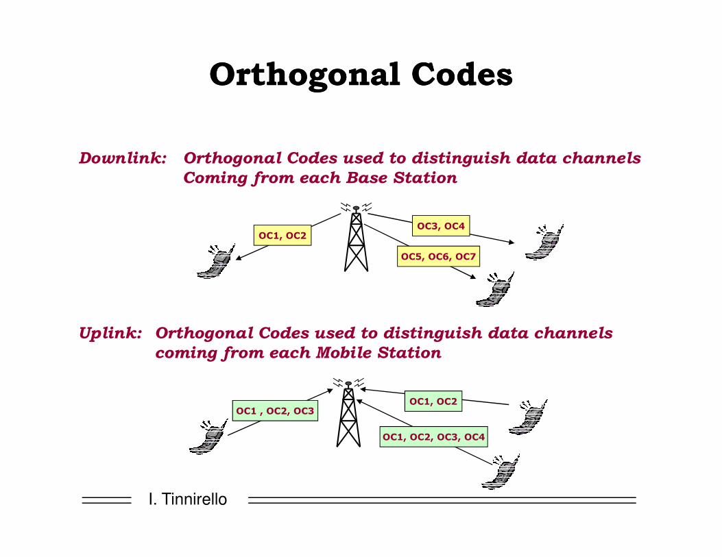
Orthogonal CodesOrthogonal Codes
OC1, OC2OC3, OC4
OC5, OC6, OC7
Downlink: Orthogonal Codes used to distinguish data channels
Coming from each Base Station
I. Tinnirello
OC1 , OC2, OC3OC1, OC2
OC1, OC2, OC3, OC4
Uplink: Orthogonal Codes used to distinguish data channels
coming from each Mobile Station

Orthogonal CDMA: SummaryOrthogonal CDMA: Summary
� CDMA allows multiple data streams to be sent on the same RF carrier
� Perfect isolation between data streams
� Timing between data streams must be exact
� Maximum number of data channels = orthogonal code
length
�The longer the code, the slower the data rate
CodeDivision Multiple
Access
Data 1
Data 2
Data 3
I. Tinnirello
� Code space can be rapidly re-allocated to match user data rate requirements
� CDMA advantages are limited in practice
� Multipath, small timing errors, and motion-related
effects diminish the usable code space
Each Data Stream has a unique
Orthogonal spreading code
Many users share the same frequency and time
IS-95, cdma2000, WCDMA
Frequency
...

Orthogonal codes: do they work?Orthogonal codes: do they work?Case III: Correlation using Orthogonal Codes
(a) Same Orthogonal code; (b) Different Orthogonal codes; (c) Same code with non-zero time offset
Input Data +1 -1 +1
-1 +1 –1 +1 +1 –1 +1 -1 -1 +1 –1 +1 +1 –1 +1 -1 -1 +1 –1 +1 +1 –1 +1 -1
-1 +1 –1 +1 +1 –1 +1 -1 +1 –1 +1 –1 –1 +1 –1 +1 -1 +1 –1 +1 +1 –1 +1 -1
Orthogonal code
in Transmitter
Transmitted
Sequence
x x x
= = =Transmitter
I. Tinnirello
-1 +1 –1 +1 +1 –1 +1 -1 +1 +1 +1 +1 +1 +1 +1 +1 -1 -1 +1 –1 +1 +1 –1 +1
+1 +1 +1 +1 +1 +1 +1 +1 +1 –1 +1 –1 –1 +1 –1 +1 +1 –1 –1 –1 +1 –1 –1 -1
Orthogonal Code
used in Receiver
8 0 -4
Integrate
Result
+1 0-0.5
Divide by
Code Length
Integrate Integrate Integrate
x x x
= = =Receiver

PseudoPseudo--Noise Code PropertiesNoise Code Properties
� Orthogonal codes have a limit: require perfect synchronization!
� Could we do something different losing a perfect orthogonality??? Yes! Pseudo Noise Codes
� PN Codes are repeating, defined-length blocks of 1’s and 0’s
�Approximately equal number of 1’s and 0’s
�The statistics appear randomly distributed within the block
� Good Autocorrelation and Cross-Correlation properties
�PN Code cross-correlation properties do not depend on time
I. Tinnirello
�PN Code cross-correlation properties do not depend on time
alignment (time offset)
Example of a 32-bit (25) PN code:01101000110101001010011010100111

PN Code GenerationPN Code Generation
�PN Codes: Generation using a Shift Register
ββββ1 ββββ2 ββββ3 ββββN
I. Tinnirello
• ββββn values are 0 or 1 (determined by the specified “generator polynomial”)
• Maximal-length (m-sequence) has a repetitive cycle of ( 2N - 1 ) bits
• A code of 16 777 215 bits can be replicated using only a 24-bit “key”
D D
clock
D D
1010010010001110101...
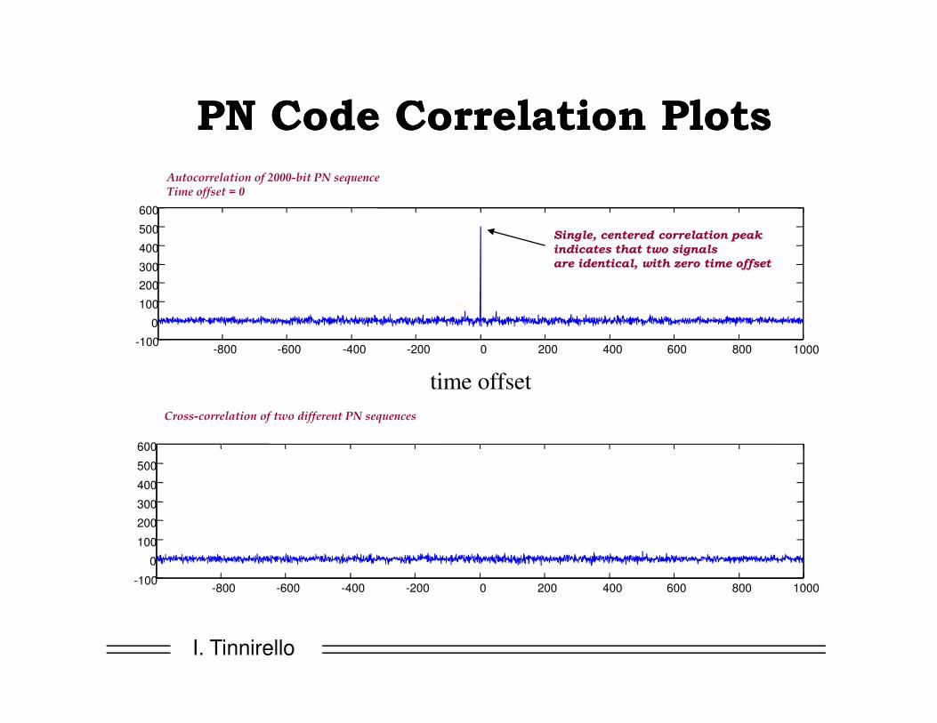
PN Code Correlation PlotsPN Code Correlation Plots
Autocorrelation of 2000-bit PN sequenceTime offset = 0
-800 -600 -400 -200 0 200 400 600 800 1000-100
0
100
200
300
400
500
600
Single, centered correlation peak
indicates that two signals
are identical, with zero time offset
I. Tinnirello
Cross-correlation of two different PN sequences
-800 -600 -400 -200 0 200 400 600 800 1000-100
0
100
200
300
400
500
600
time offset

Code Correlation: Key PointsCode Correlation: Key Points
� TX, RX use same codes, at the same time offset�PN Codes: 100% correlation�Orthogonal Codes: 100% correlation
� TX, RX use different codes�PN Codes: “Low” (noise-like) correlation at any time offset
Avg. correlation proportional to 1/(code length)�Orthogonal Codes: 0% Correlation
I. Tinnirello
� TX, RX use same codes, but at different time offsets�PN Codes: “Low” (noise-like) correlation�Orthogonal Codes: Unpredictable results

Spread Spectrum Multiple AccessSpread Spectrum Multiple Access
PN 1
RF
Modulation
Transmitter 1
PN 2
RF
Modulation
Transmitter 2
RF
PN 3Receiver
I. Tinnirello
PN 3
RF
Modulation
Transmitter 3
PN 4
RF
Modulation
Transmitter 4
RF
Demod
In this example, the receiver correlates the composite received signal using PN code 3.
The result is the recovered transmission from Transmitter #3, plus some spread spectrum interference from transmitters #1, #2, and #4

SSMA PN Code PlanningSSMA PN Code Planning
PN PN
PN1 PN1
Cell Site “1” transmits using PN code 1
Uplink: PN Code used to distinguish each Mobile Station
Downlink: PN Code used to distinguish each Base Station
I. Tinnirello
PN3 PN4
PN5 PN6
PN2 PN2
Cell Site “2” transmits using PN code 2

SSMA PN Code PlanningSSMA PN Code Planning
Spread Spectrum Code Planning Example
PN2
PN3PN7PN1
PN2
PN3PN7
PN2
NNNN
WWWW EEEE
I. Tinnirello
PN1
PN2
PN3PN7
PN6 PN4
PN5
PN1
PN2
PN3PN7
PN6 PN4
PN5 PN1
PN2
PN3PN7
PN6 PN4
PN5
PN1
PN6 PN4
PN5
PN6 PN4
PN5 PN1
PN3PN7
PN6 PN4
PN5
SSSS

SSMA: SummarySSMA: Summary
� SSMA Utilization
� Used to distinguish the transmission source (Base Station or Mobile Station) in cellular CDMA systems
�Provides good (but not 100%) separation between multiple transmissions in the same geographic area, on the same frequency
� Works regardless of time-of-arrival delays
� Code Planning instead of Frequency Planning
�Frequency Reuse = 1
SpreadSpectrumMultiple
Access
Tx 1
Tx 2
Tx 3
I. Tinnirello
�Frequency Reuse = 1
� SSMA Limitations
� Imperfect signal separation
�Number of simultaneous transmitters in one area is limited by the Spreading Factor
� Not good for transmitting multiple data streams from one transmitter
Each Transmitterhas a unique
PN spreading code
Several Transmitters share the same frequency
and time
Frequency
...
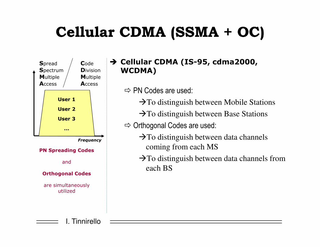
Cellular CDMA (SSMA + OC)Cellular CDMA (SSMA + OC)
� Cellular CDMA (IS-95, cdma2000, WCDMA)
� PN Codes are used:
�To distinguish between Mobile Stations
�To distinguish between Base Stations
� Orthogonal Codes are used:
CodeDivision Multiple
Access
SpreadSpectrumMultiple
Access
User 1
User 2
User 3
I. Tinnirello
� Orthogonal Codes are used:
�To distinguish between data channels
coming from each MS
�To distinguish between data channels from
each BS
PN Spreading Codes
and
Orthogonal Codes
are simultaneously utilized
Frequency
...

Cellular CDMA (SSMA + OC)Cellular CDMA (SSMA + OC)
2 data channels
(voice, control)
PN3 + OC1 + OC2
2 data channels
(14 kbps data, control)
PN4 + OC1 + OC2
2 data channels
(voice, control)
PN1 + OC1 + OC2
1 data channels
(control)
PN1 + OC3
Voice
Conversation Uplink
Packet Data
Pilot, Broadcast
PN1 + OCP + OCB
I. Tinnirello
3 data channels
(voice, video, control)
PN2 + OC1 + OC2 + OC3
3 data channels
(voice, video, control)
PN5 + OC1 + OC2 + OC3
4 data channels
(384 kbps data, voice, video, control)
PN6 + OC1 + OC2 + OC3 + OC4
4 data channels
(384 kbps data, voice, video, control)
PN2 + OC4 + OC5 + OC6 + OC7Videoconference
Videoconference
with Data
Pilot, Broadcast
PN2 + OCP + OCB

The The NeedNeed ofof PowerPower ControlControl
� Pseudo-noise code work properly if interfering signals have comparable power!
� Let r be the sum of two interfering signals obtained from data d1 (by user 1) and d2 (by user 2), and pn1 and pn2 be the vectors containing the pseudo code used by user 1 and user 2:
� r = d1 pn1 + d2 pn2
� Being <pn1, pn2> =ε≈ 0, receiver interested in data transmitted by user 1 can correlate r with pn
I. Tinnirello
1 2
by user 1 can correlate r with pn1:� < r , pn1 >= d1 <pn1 , pn1 > + d2 < pn1 , pn2>≈d1+ ε
� But.. when the interfering signal is much higher than the useful one, the residual interference of pseudo-noise correlation can destroy the data:
� r = d1 pn1 + K d2 pn2
� < r , pn1 >= d1 <pn1 , pn1 > + K d2 < pn1 , 2 pn2>≈d1+K ε=???

Power ControlPower Control Strategies Strategies
�To correct the power level on the uplink
�Closed loop power control
�Open loop power control
I. Tinnirello
�Outer loop power control
�To correct the power level on the downlink
�Downlink power control

Closed Loop Power Control Closed Loop Power Control
The antenna controller controls the UE
� 3-phase mechanism
1. UE transmits
2. Antenna controller measures the received power level and
compares this with a threshold
I. Tinnirello
compares this with a threshold
3. Antenna controller tells the UE whether it has to increase or
decrease its transmit power (executed periodically)
� “Closed Loop” since is a mechanism with feedback
� It is quite accurate, however it performs better if the initial power level is not too far from the desired value

Open Loop Power Control Open Loop Power Control
UE controls itself
� 2-phase mechanism
1. UE measures the interference level on the signal
transmitted from the antenna controller
I. Tinnirello
transmitted from the antenna controller
2. UE uses an internal algorithm to correct the power level
transmitted on the uplink so that the estimated SINR is
above a certain threshold
� “Open Loop” since there is not feedback
� It is quite inaccurate

Outer Loop Power ControlOuter Loop Power Control
It is a ‘control on the control’ performed at
the BS
�Outer loop power control modifies the
threshold value that is employed in the
I. Tinnirello
threshold value that is employed in the
closed and open loop power control
�Used to adapt the radio transmission to
the desired level of QoS (e.g., packet error
rate)

DownlinkDownlink Power ControlPower Control
� 3-phase mechanism:
�UE measures the power received from the antenna controller and
asks the antenna controller for an increase or a reduction in the
UE controls the antenna controller by sending a feedback (closed loop), but more slowly than the uplink feedback
I. Tinnirello
asks the antenna controller for an increase or a reduction in the
transmitted power
�The power level used by the antenna controller is derived by
averaging the feedback from all users -> not a very accurate power
control
�Performed @ lower frequency (more slowly) because the
communication on downlink is less critical than on uplink

FDDFDD--WCDMA WCDMA ParametersParameters
Multiple access scheme WCDMA
Channel spacing 5 MHz
Chip rate 3.84 Mchip/s
Number of slots per frame 15
Frame length 10 ms
I. Tinnirello
Frame length 10 ms
Multirate concept multicode
Modulation Down-link: QPSK Up-link: Dual Code BPSK
Detection Coherent
TX - RX frequency separation
130 MHz minimum

TDDTDD--WCDMA WCDMA ParametersParameters
Multiple access scheme TDMA/WCDMA
Channel spacing 5 MHz
Chip rate 3.84 Mchip/s
Number of slots per frame 15
Frame length 10 ms
I. Tinnirello
Frame length 10 ms
Multirate concept multislot /multicode
Modulation QPSK
Detection Coherent, based on midamble

PhysicalPhysical, , TransportTransport, , LogicalLogical
ChannelsChannels
I. Tinnirello
ChannelsChannels

LogicalLogical ChannelsChannels
� Logical Channels are the services offered by the MAC layer to the RLC layer
� Control Channels
� Broadcast Control Channel (BCCH) - DL� Paging Control Channel (PCCH) - DL� Common Control Channel (CCCH) - DL&UL, used when there isn’t a UE
connection or for cell reselection
I. Tinnirello
connection or for cell reselection� Dedicated Control Channel (DCCH) - DL&UL
� Traffic Channel
� Dedicated Traffic Channel (DTCH) – DL&UL� Common Traffic Channel (CTCH) – DL

Transport ChannelsTransport Channels
�A Transport Channel is defined by how and with which characteristics (quality level) data is transferred over the air interface
�Dedicated CHannels (DCH) uplink & downlink
I. Tinnirello
TrCHPhyCH mapping
�Common CHannels (CCH) uplink or downlink
�Shared CHannels (SCH) uplink or downlink

Transport ChannelsTransport Channels
�Packets (e.g., RLC PDU) transferred over transport channels are called Transport Blocks (TBs)
�Several packets can be transmitted
I. Tinnirello
�Several packets can be transmitted simultaneously in Transport Block Sets (TBSs)
�A Transport Block or a Transport Block Set is passed to the PHY layer every Transmisson Time Interval (TTI) (TTI=k Frame, with k=1,2,..)

TransportTransport ChannelsChannels TypesTypes
� Dedicated Transport Channels
� Dedicated Channel (DCH) – DL&UL� Common Transport Channels
� Broadcast Channel (BCH) – DL�For system information
� Paging Channel (PCH) - DL� Random Access Channel (RACH) – UL
�For short and single packet transmissions
� Shared Transport Channels
I. Tinnirello
� Shared Transport Channels
� Common Packet Channel (CPCH) – UL�Shared among different users for bursty transfers
� Downlink Shared Channel (DSCH) – DL�Shared among different users for bursty & pt2pt
transmissions, associated to a DCH which carries control
information
� Forward Access Channel (FACH) – DL�Short & bursty transmissions

CCCH DCCH DCCHCTCHCCCHBCCHPCCH
Uplink Downlink
DTCH DTCHLogical channels
TransportTransport ChannelChannel MappingMapping
I. Tinnirello
PCH DCHDSCHFACHBCHDCHCPCHRACH
Logical channels
Transport channels

PhysicalPhysical ChannelChannel in FDDin FDD
� A physical channel corresponds to:
�a specific carrier frequency�a code (scrambling code, channelization code)�on the uplink, a relative phase (0, π/2)
� Physical transmission is organized in Radio Frames and Slots� Slots do not define phy channels, but are used for periodiic control
I. Tinnirello
� Slots do not define phy channels, but are used for periodiic control
� Each Radio Frame consists of 15 slots
frame x frame x+1
2560 chip
sµ66725603840000
1=×
ms101525603840000
1=××

PhysicalPhysical ChannelsChannels in FDDin FDD
� DCH: Dedicated Channel � Dedicated Physical Data Channel (DPDCH)� Dedicated Physical Control Channel (DPCCH)
� PRACH: Physical Random Access Channel � CPCH: Common Packet Channel
� Physical Common Packet Channel (PCPCH) – CSMA/CD access � Common Pilot Channel (CPICH) - macrodiversity
� BCH: Broadcast Channel� Primary Common Control Physical Channel (P-CCPCH)
I. Tinnirello
� Primary Common Control Physical Channel (P-CCPCH)� FACH/PCH: Forward Access Channel
� Secondary Common Control Physical Channel (S-CCPCH)� Synchronization Channel (SCH)
� DSCH: Downlink Shared Channel� Indicators:
� Acquisition Indicator Channel (AICH)� Access Preamble Acquisition Indicator Channel (AP-AICH)� Paging Indicator Channel (PICH)� CPCH Status Indicator Channel (CSICH)� Collision-Detection/Channel-Assignment Indicator Channel (CN/CA-ICH)

PCH DCHDSCHFACH BCH
DCH
CPCHRACH
Transport channels
Uplink Downlink
PhysicalPhysical ChannelChannel MappingMapping
I. Tinnirello
PRACH PCPCH SCCPCH PCCPCH DPDCH
DPCCH
SCHCPICH
AICH
PICH
CSICHPhysical channels
DPCHCD/CA-
ICH PDSCH

Uplink Physical Channels: ExampleUplink Physical Channels: Example
Dedicated PhysicalData Channel (DPDCH)
Dedicated PhysicalControl Channel
Data
Pilot FBI TPCTFCI
I. Tinnirello
Control Channel (DPCCH)
Slot 0 Slot 1 Slot i Slot 14
Frame = 10 ms
Pilot=known bit sequence; TFCI=Transport Format Combination ID;FBI=Feedback information; TPC=Power Control Information

Downlink Physical Channels: Downlink Physical Channels:
ExampleExample
DataPilot TPC TFCI
DPCCH DPDCH
I. Tinnirello
Slot 1 Slot 2 Slot i Slot 15
Frame = 10 ms

UplinkUplink VariableVariable RateRate
10 ms
1-rate
1/2-rate
1/4-rate
Rate can be varied on a per-frame basis
I. Tinnirello
Variable
rate
1/4-rate
0-rate
: DPCCH (Pilot+TPC+TFCI+FBI)
: DPDCH (Data)
R = 1 R = 1/2 R = 0 R = 0 R = 1/2

1-rate
1/2-rate
0.666 ms
DownlinkDownlink VariableVariable RateRate
Rate can be varied on a per-frame basis
I. Tinnirello
1/4-rate
0-rate
: DPCCH-part (Pilot+TPC+TFCI)
: DPDCH-part (Data)
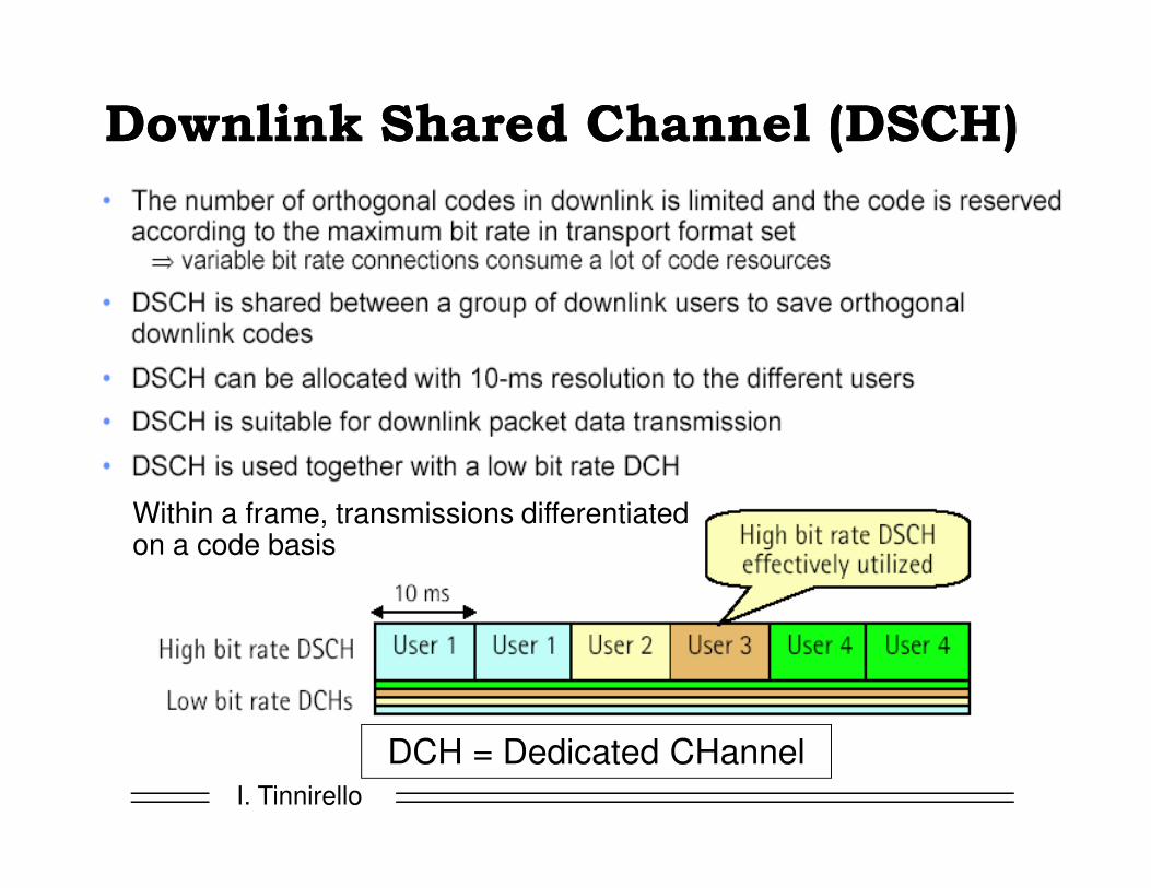
DownlinkDownlink SharedShared ChannelChannel (DSCH)(DSCH)
I. Tinnirello
Within a frame, transmissions differentiated on a code basis
DCH = Dedicated CHannel

WCDMA Air InterfaceWCDMA Air Interface
Common Channels - RACH (uplink) and FACH (downlink)
• Random Access, No Scheduling• Low Setup Time• No Feedback Channel, No Fast Power Control, Use Fixed Transmission Power• Poor Link-level Performance and Higher Interference• Suitable for Short, Discontinuous Packet Data
RACH
FACH 1 2 1 3
3P
1P
I. Tinnirello
Common Channel - CPCH (uplink)• Extension for RACH• Reservation across Multiple Frames• Can Utilize Fast Power Control, Higher Bit Rate• Suitable for Short to Medium Sized Packet Data
RACH 3P
3 1P
1
CPCH 1P
12P
2
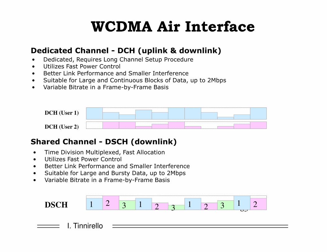
WCDMA Air InterfaceWCDMA Air Interface
Dedicated Channel - DCH (uplink & downlink)• Dedicated, Requires Long Channel Setup Procedure• Utilizes Fast Power Control• Better Link Performance and Smaller Interference• Suitable for Large and Continuous Blocks of Data, up to 2Mbps• Variable Bitrate in a Frame-by-Frame Basis
DCH (User 1)
DCH (User 2)
I. Tinnirello
83
Shared Channel - DSCH (downlink)
• Time Division Multiplexed, Fast Allocation• Utilizes Fast Power Control• Better Link Performance and Smaller Interference• Suitable for Large and Bursty Data, up to 2Mbps• Variable Bitrate in a Frame-by-Frame Basis
DCH (User 2)
DSCH 1 2 3 1 2 3 1 2 3 1 2

WCDMA Air InterfaceWCDMA Air Interface
Summary
• 5 MHz Bandwidth -> High Capacity, Multipath Diversity• Variable Spreading Factor -> Bandwidth on Demand
RACH
FACH 1 2 1 3
3P
3 1P
1
I. Tinnirello
CPCH
DCH (User 1)
DCH (User 2)
DSCH
1P
1
2P
2
1 2 3 1 2 31 2 3 1 2