lecture 12 - university of california, berkeleyee105/fa07/lectures/lecture... · 2007-10-03 ·...
TRANSCRIPT

Lecture 12
ANNOUNCEMENTS• Review session: 3 5PM Friday (10/5) in 306 Soda (HP Auditorium)• Review session: 3‐5PM Friday (10/5) in 306 Soda (HP Auditorium)• Midterm #1 (Thursday 10/11, 3:30PM‐5:00PM) location:
• 106 Stanley Hall: Students with last names starting with A‐L
OUTLINE
• 306 Soda Hall: Students with last names starting with M‐Z
OUTLINE• Cascode Stage (cont’d)
– supplementary remarkssupplementary remarks
• Current Mirrors
Reading: Chapter 9 2
EE105 Fall 2007 Lecture 12, Slide 1 Prof. Liu, UC Berkeley
Reading: Chapter 9.2

Review: Cascode Stage Rout
• The impedance seen looking into the collector can be boosted significantly by using a BJT for emitter degeneration, with asignificantly by using a BJT for emitter degeneration, with a relatively small reduction in headroom.
||)]||(1[ rrrrrgR ++=( )1211
12112
||||)]||(1[
π
ππ
rrrgRrrrrrgR
OOmout
OOOmout
≈++=
EE105 Fall 2007 Lecture 12, Slide 2 Prof. Liu, UC Berkeley

Another View of a Cascode Stage
• Instead of considering a cascode as Q2 degenerating Q we can also think of it as Q stacked on top of QQ1, we can also think of it as Q1 stacked on top of Q2 (current source) to boost Q2’s output impedance.
EE105 Fall 2007 Lecture 12, Slide 3 Prof. Liu, UC Berkeley

Temperature and Supply‐Voltage Dependence of Bias CurrentDependence of Bias Current
• Circuits should be designed to operate properly over a range of supply voltages and temperaturesa range of supply voltages and temperatures.
• For the biasing scheme shown below, I1 depends on the temperature as well as the supply voltage, sincethe temperature as well as the supply voltage, since VT and IS depend on temperature.
VVS
ReII TBE /
1 =
CCBE VRR
RV21
2
+≅
EE105 Fall 2007 Lecture 12, Slide 4 Prof. Liu, UC Berkeley

Concept of a Current Mirror• Circuit designs to provide a supply‐ and temperature‐independent current exist, but require many p , q ytransistors to implement.
“golden current source”
• A current mirror is used to replicate the current from a “golden current source” to other locations.
EE105 Fall 2007 Lecture 12, Slide 5 Prof. Liu, UC Berkeley

Current Mirror Circuitry• Diode‐connected QREF produces an output voltage VX that forces I to be equal to I if Q is identical to Qforces Icopy1 to be equal to IREF, if Q1 is identical to QREF.
Current mirror concept Generation of required VBE Current Mirror Circuitry
⎞⎜⎛⎞
⎜⎛
REFcopy II 1
REFS
copy III
I 1,1 =
⎟⎠
⎞⎜⎜⎝
⎛=⎟
⎠
⎞⎜⎜⎝
⎛=
REFS
REFT
S
copyTX I
IVI
VV,1,
1 lnln
EE105 Fall 2007 Lecture 12, Slide 6 Prof. Liu, UC Berkeley
REFREFS
copy I ,1

Bad Current Mirror Example 1
• If the collector and base of QREF are not shorted together, there will not be a path for the base currents to flow, so that Icopy is zero.
EE105 Fall 2007 Lecture 12, Slide 7 Prof. Liu, UC Berkeley

Bad Current Mirror Example 2
Alth h it id th f b t t fl• Although it provides a path for base currents to flow, this biasing approach is no better than a resistive voltage divider
EE105 Fall 2007 Lecture 12, Slide 8 Prof. Liu, UC Berkeley
voltage divider.

Multiple Copies of IREF• Multiple copies of IREF can be generated at different locations by applying the current mirror concept tolocations by applying the current mirror concept to multiple transistors.
REFjS
j II
I ,=
EE105 Fall 2007 Lecture 12, Slide 9 Prof. Liu, UC Berkeley
REFREFS
jcopy II
I,
,

Current Scaling• By scaling the emitter area of Qj by a factor of n with respect to the emitter area of Q I is scaled by arespect to the emitter area of QREF, Icopy,j is scaled by a factor of n with respect to IREF.– This is equivalent to placing n unit‐sized transistors in parallel.q p g p
nII =EE105 Fall 2007 Lecture 12, Slide 10 Prof. Liu, UC Berkeley
REFjcopy nII =,

Example: Scaled Currents
EE105 Fall 2007 Lecture 12, Slide 11 Prof. Liu, UC Berkeley

Fractional Scaling• A fraction of IREF can be created in Q1 by scaling up the emitter area of Qthe emitter area of QREF.
⎞⎜⎜⎛
= XVII exp3⎞
⎜⎜⎛
= XVII exp⎠
⎜⎜⎝
=T
SREF VII exp3
⎠⎜⎜⎝
=T
Scopy VII exp
II 1=
EE105 Fall 2007 Lecture 12, Slide 12 Prof. Liu, UC Berkeley
REFcopy II3
=

Example: Different Mirroring Ratios• Using the concept of current scaling and fractional scaling I = 0 05mA and I = 0 5mA derivedscaling, Icopy1 = 0.05mA and Icopy2 = 0.5mA, derived from a single 0.2mA reference current source (IREF).
EE105 Fall 2007 Lecture 12, Slide 13 Prof. Liu, UC Berkeley

Effect of Base Currents
ββcopycopy
REFCREF
InI
II ++= , ββn
In
II copy
REFC =,
( )111 ++=
n
nII REFcopy
EE105 Fall 2007 Lecture 12, Slide 14 Prof. Liu, UC Berkeley
( )11 ++ nβ

Improved Mirroring Accuracy• Use QF (rather than IREF) to supply the base currents of QREF and Q1, reduce the mirroring error by a factor of β.QREF Q1, g y β
copycopy IIII +=≅
REFCFBREF III ,, +=
ββFEFC nII +=≅ ,,
⎞⎜⎛ +≅ 11I
I copy
⎠⎜⎝
+≅ 12, nI py
FB βn
II copy
REFC =,
( )111 ++=
n
nII REFcopy
EE105 Fall 2007 Lecture 12, Slide 15 Prof. Liu, UC Berkeley
( )11 2 ++ nβ
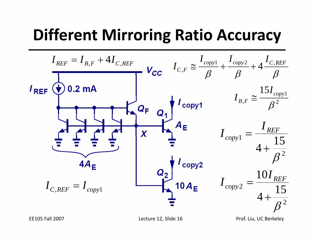
Different Mirroring Ratio Accuracy
REFCFBREF III ,, 4+=βββREFCcopycopy
FC
IIII ,21
, 4++≅βββ
21
,
15β
copyFB
II ≅
1 =REFII
β
2
1 154β
+copyI
2 154
10
+= REF
copyII
1, copyREFC II =
EE105 Fall 2007 Lecture 12, Slide 16 Prof. Liu, UC Berkeley
24β
+

PNP Current Mirror
• A PNP BJT current mirror can be used as a current‐source load for an NPN BJT amplifier stagesource load for an NPN BJT amplifier stage.
EE105 Fall 2007 Lecture 12, Slide 17 Prof. Liu, UC Berkeley

Generation of IREF for a PNP BJT Current MirrorPNP‐BJT Current Mirror
• Neglecting base currents, the currents flowing through Q and Q are the same
EE105 Fall 2007 Lecture 12, Slide 18 Prof. Liu, UC Berkeley
through QM and QREF2 are the same.

Current Mirror with Discrete BJTs
• If QREF and Q1 are discrete NPN BJTs, IREF and Icopy1 can differ dramatically due to I mismatchdiffer dramatically, due to IS mismatch.
EE105 Fall 2007 Lecture 12, Slide 19 Prof. Liu, UC Berkeley